EP2109399B1 - Motion estimation in treatment planning - Google Patents
Motion estimation in treatment planning Download PDFInfo
- Publication number
- EP2109399B1 EP2109399B1 EP08702527.6A EP08702527A EP2109399B1 EP 2109399 B1 EP2109399 B1 EP 2109399B1 EP 08702527 A EP08702527 A EP 08702527A EP 2109399 B1 EP2109399 B1 EP 2109399B1
- Authority
- EP
- European Patent Office
- Prior art keywords
- motion
- projection data
- region
- interest
- generating
- Prior art date
- Legal status (The legal status is an assumption and is not a legal conclusion. Google has not performed a legal analysis and makes no representation as to the accuracy of the status listed.)
- Not-in-force
Links
- 238000011282 treatment Methods 0.000 title claims description 44
- 238000000034 method Methods 0.000 claims description 38
- 239000013598 vector Substances 0.000 claims description 16
- 230000002596 correlated effect Effects 0.000 claims description 14
- 238000004458 analytical method Methods 0.000 claims description 11
- 241001417495 Serranidae Species 0.000 claims description 8
- 238000001959 radiotherapy Methods 0.000 claims description 7
- 238000002560 therapeutic procedure Methods 0.000 claims description 7
- 230000000737 periodic effect Effects 0.000 claims description 6
- 238000001914 filtration Methods 0.000 claims description 4
- 238000002600 positron emission tomography Methods 0.000 description 17
- 206010028980 Neoplasm Diseases 0.000 description 16
- 238000003384 imaging method Methods 0.000 description 11
- 230000006870 function Effects 0.000 description 10
- 230000005855 radiation Effects 0.000 description 9
- 238000002591 computed tomography Methods 0.000 description 8
- 230000003902 lesion Effects 0.000 description 8
- 230000000241 respiratory effect Effects 0.000 description 8
- 230000029058 respiratory gaseous exchange Effects 0.000 description 7
- 230000002123 temporal effect Effects 0.000 description 7
- 230000000694 effects Effects 0.000 description 6
- 210000003484 anatomy Anatomy 0.000 description 5
- 239000003795 chemical substances by application Substances 0.000 description 4
- 230000000875 corresponding effect Effects 0.000 description 4
- 210000001519 tissue Anatomy 0.000 description 4
- 239000002131 composite material Substances 0.000 description 3
- 238000010586 diagram Methods 0.000 description 3
- 230000004075 alteration Effects 0.000 description 2
- 230000000747 cardiac effect Effects 0.000 description 2
- 238000012937 correction Methods 0.000 description 2
- 210000004072 lung Anatomy 0.000 description 2
- 238000013178 mathematical model Methods 0.000 description 2
- 238000005259 measurement Methods 0.000 description 2
- 238000012986 modification Methods 0.000 description 2
- 230000004048 modification Effects 0.000 description 2
- 230000004044 response Effects 0.000 description 2
- 206010021143 Hypoxia Diseases 0.000 description 1
- 238000012879 PET imaging Methods 0.000 description 1
- 230000001133 acceleration Effects 0.000 description 1
- 238000002583 angiography Methods 0.000 description 1
- 238000013459 approach Methods 0.000 description 1
- 210000000988 bone and bone Anatomy 0.000 description 1
- 230000008859 change Effects 0.000 description 1
- 238000001514 detection method Methods 0.000 description 1
- 238000003745 diagnosis Methods 0.000 description 1
- 238000002059 diagnostic imaging Methods 0.000 description 1
- 239000003814 drug Substances 0.000 description 1
- 238000011156 evaluation Methods 0.000 description 1
- 238000011347 external beam therapy Methods 0.000 description 1
- 238000002594 fluoroscopy Methods 0.000 description 1
- 230000001146 hypoxic effect Effects 0.000 description 1
- 230000000266 injurious effect Effects 0.000 description 1
- 238000002721 intensity-modulated radiation therapy Methods 0.000 description 1
- 208000020816 lung neoplasm Diseases 0.000 description 1
- 208000037841 lung tumor Diseases 0.000 description 1
- 238000012544 monitoring process Methods 0.000 description 1
- 210000004165 myocardium Anatomy 0.000 description 1
- 238000002727 particle therapy Methods 0.000 description 1
- 230000008569 process Effects 0.000 description 1
- 239000000700 radioactive tracer Substances 0.000 description 1
- 238000007674 radiofrequency ablation Methods 0.000 description 1
- 230000009467 reduction Effects 0.000 description 1
- 238000011160 research Methods 0.000 description 1
- 238000002603 single-photon emission computed tomography Methods 0.000 description 1
- 210000000130 stem cell Anatomy 0.000 description 1
- 238000009210 therapy by ultrasound Methods 0.000 description 1
- 238000003325 tomography Methods 0.000 description 1
- 238000011277 treatment modality Methods 0.000 description 1
Images


Classifications
-
- A—HUMAN NECESSITIES
- A61—MEDICAL OR VETERINARY SCIENCE; HYGIENE
- A61B—DIAGNOSIS; SURGERY; IDENTIFICATION
- A61B6/00—Apparatus or devices for radiation diagnosis; Apparatus or devices for radiation diagnosis combined with radiation therapy equipment
- A61B6/02—Arrangements for diagnosis sequentially in different planes; Stereoscopic radiation diagnosis
- A61B6/03—Computed tomography [CT]
- A61B6/032—Transmission computed tomography [CT]
-
- A—HUMAN NECESSITIES
- A61—MEDICAL OR VETERINARY SCIENCE; HYGIENE
- A61B—DIAGNOSIS; SURGERY; IDENTIFICATION
- A61B6/00—Apparatus or devices for radiation diagnosis; Apparatus or devices for radiation diagnosis combined with radiation therapy equipment
- A61B6/02—Arrangements for diagnosis sequentially in different planes; Stereoscopic radiation diagnosis
- A61B6/03—Computed tomography [CT]
- A61B6/037—Emission tomography
-
- A—HUMAN NECESSITIES
- A61—MEDICAL OR VETERINARY SCIENCE; HYGIENE
- A61B—DIAGNOSIS; SURGERY; IDENTIFICATION
- A61B6/00—Apparatus or devices for radiation diagnosis; Apparatus or devices for radiation diagnosis combined with radiation therapy equipment
- A61B6/52—Devices using data or image processing specially adapted for radiation diagnosis
- A61B6/5258—Devices using data or image processing specially adapted for radiation diagnosis involving detection or reduction of artifacts or noise
- A61B6/5264—Devices using data or image processing specially adapted for radiation diagnosis involving detection or reduction of artifacts or noise due to motion
- A61B6/527—Devices using data or image processing specially adapted for radiation diagnosis involving detection or reduction of artifacts or noise due to motion using data from a motion artifact sensor
-
- A—HUMAN NECESSITIES
- A61—MEDICAL OR VETERINARY SCIENCE; HYGIENE
- A61N—ELECTROTHERAPY; MAGNETOTHERAPY; RADIATION THERAPY; ULTRASOUND THERAPY
- A61N5/00—Radiation therapy
- A61N5/10—X-ray therapy; Gamma-ray therapy; Particle-irradiation therapy
- A61N5/103—Treatment planning systems
-
- A—HUMAN NECESSITIES
- A61—MEDICAL OR VETERINARY SCIENCE; HYGIENE
- A61B—DIAGNOSIS; SURGERY; IDENTIFICATION
- A61B5/00—Measuring for diagnostic purposes; Identification of persons
- A61B5/05—Detecting, measuring or recording for diagnosis by means of electric currents or magnetic fields; Measuring using microwaves or radio waves
- A61B5/055—Detecting, measuring or recording for diagnosis by means of electric currents or magnetic fields; Measuring using microwaves or radio waves involving electronic [EMR] or nuclear [NMR] magnetic resonance, e.g. magnetic resonance imaging
-
- A—HUMAN NECESSITIES
- A61—MEDICAL OR VETERINARY SCIENCE; HYGIENE
- A61B—DIAGNOSIS; SURGERY; IDENTIFICATION
- A61B5/00—Measuring for diagnostic purposes; Identification of persons
- A61B5/72—Signal processing specially adapted for physiological signals or for diagnostic purposes
- A61B5/7203—Signal processing specially adapted for physiological signals or for diagnostic purposes for noise prevention, reduction or removal
- A61B5/7207—Signal processing specially adapted for physiological signals or for diagnostic purposes for noise prevention, reduction or removal of noise induced by motion artifacts
- A61B5/721—Signal processing specially adapted for physiological signals or for diagnostic purposes for noise prevention, reduction or removal of noise induced by motion artifacts using a separate sensor to detect motion or using motion information derived from signals other than the physiological signal to be measured
-
- A—HUMAN NECESSITIES
- A61—MEDICAL OR VETERINARY SCIENCE; HYGIENE
- A61B—DIAGNOSIS; SURGERY; IDENTIFICATION
- A61B5/00—Measuring for diagnostic purposes; Identification of persons
- A61B5/72—Signal processing specially adapted for physiological signals or for diagnostic purposes
- A61B5/7271—Specific aspects of physiological measurement analysis
- A61B5/7285—Specific aspects of physiological measurement analysis for synchronizing or triggering a physiological measurement or image acquisition with a physiological event or waveform, e.g. an ECG signal
- A61B5/7289—Retrospective gating, i.e. associating measured signals or images with a physiological event after the actual measurement or image acquisition, e.g. by simultaneously recording an additional physiological signal during the measurement or image acquisition
-
- A—HUMAN NECESSITIES
- A61—MEDICAL OR VETERINARY SCIENCE; HYGIENE
- A61N—ELECTROTHERAPY; MAGNETOTHERAPY; RADIATION THERAPY; ULTRASOUND THERAPY
- A61N5/00—Radiation therapy
- A61N5/10—X-ray therapy; Gamma-ray therapy; Particle-irradiation therapy
- A61N5/1048—Monitoring, verifying, controlling systems and methods
- A61N5/1049—Monitoring, verifying, controlling systems and methods for verifying the position of the patient with respect to the radiation beam
- A61N2005/1052—Monitoring, verifying, controlling systems and methods for verifying the position of the patient with respect to the radiation beam using positron emission tomography [PET] single photon emission computer tomography [SPECT] imaging
-
- A—HUMAN NECESSITIES
- A61—MEDICAL OR VETERINARY SCIENCE; HYGIENE
- A61N—ELECTROTHERAPY; MAGNETOTHERAPY; RADIATION THERAPY; ULTRASOUND THERAPY
- A61N5/00—Radiation therapy
- A61N5/10—X-ray therapy; Gamma-ray therapy; Particle-irradiation therapy
- A61N5/103—Treatment planning systems
- A61N5/1037—Treatment planning systems taking into account the movement of the target, e.g. 4D-image based planning
-
- A—HUMAN NECESSITIES
- A61—MEDICAL OR VETERINARY SCIENCE; HYGIENE
- A61N—ELECTROTHERAPY; MAGNETOTHERAPY; RADIATION THERAPY; ULTRASOUND THERAPY
- A61N5/00—Radiation therapy
- A61N5/10—X-ray therapy; Gamma-ray therapy; Particle-irradiation therapy
- A61N5/1048—Monitoring, verifying, controlling systems and methods
- A61N5/1064—Monitoring, verifying, controlling systems and methods for adjusting radiation treatment in response to monitoring
- A61N5/1065—Beam adjustment
- A61N5/1067—Beam adjustment in real time, i.e. during treatment
Definitions
- the present application relates to motion estimation in treatment and treatment planning. While it finds particular application to the use of positron emission tomography (PET) data to estimate motion in connection with external radiotherapy in medicine, it also relates to other applications in which it is desirable to account for the effects of motion of an object.
- PET positron emission tomography
- US 2005/0226485 A1 discloses a rotation angiography device for angiocardiography.
- the rotation angiocardiography device comprises a radiation source attached to a C-arm, a detector and an evaluation unit which formulates models with low resolution from the projection images supplied by the detector for a moving object to be examined, and which generates movement fields for the projection images generated by the detector on the basis of the models. Movement-corrected projection images are calculated from the projection images based on the generated measurement fields, wherein the movement corrected projection images are used to formulate a three-dimensional high-resolution model of the object to be examined.
- US 2006/0074292 A1 discloses a method for dynamically tracking treatment targets such as tumors or lesions, located within an anatomical region that undergoes motion which may be periodic with cycle P.
- a four-dimensional mathematical model is established for a non-rigid motion and deformation of the anatomical region from a set of computed tomography or other three-dimensional images.
- the four-dimensional mathematical model relates three-dimensional locations of part(s) of the anatomical region with the targets being tracked as a function of the position in time within P.
- fiducial-less non-rigid image registration between pre-operative digitally reconstructed radiographs and intra-operative x-ray images the absolute position of the target and/or other part(s) of the anatomical region is determined.
- the cycle P is determined using motion sensors such as surface markers.
- the radiation beams are delivered using: 1) the results of non-rigid image registration; 2) the four-dimensional model; and 3) the position in time within P.
- US 2004/0267113 A1 discloses a method and a system for treating moving target regions in a patient's anatomy by creating radiosurgical lesions.
- Computed tomography scan data representative of a pre-operational diagnostic image of a target region are generated, wherein based on the computed tomography scan data a treatment plan is generated that defines requisite beam intensities and paths.
- the position of the target region is determined in near real time and composite motion of the target region, due to respiration and heartbeat, is tracked.
- Signals representative of the change caused by the composite motion in the position of the target region at a current time, compared to the position of the target region in the computed tomography scan, are generated and, in response, the relative position of an x-ray source and the target is adjusted, so as to account for the composite motion of the target. This process is repeated throughout the treatment. As a result, the x-rays are continually focused onto the target region in accordance with the treatment plan, while the x-ray source tracks the motion of the target region.
- US 2005/0249432 A1 discloses a method for reconstructing an image of a region of interest of an object based on chords which may fill a part of the region of interest.
- CT computed tomography
- MR magnetic resonance
- RTP radiation therapy planning
- IMRT intensity modulated radiotherapy
- Information from a functional imaging modality such as positron emission tomography (PET) provides information indicative of the functional characteristics of a tumor, and more particularly the spatial variation of a functional characteristic. This information can in turn be used to better identify regions of the tumor where an increased dose should be applied, or stated conversely, may be treated with a relatively lower dose.
- PET positron emission tomography
- hypoxic tissues within a tumor may be relatively resistant to treatment. It is thus desirable to apply a relatively higher dose to regions of the tumor that contain such tissues.
- the target volume can be affected by patient motion, as for example periodic respiratory motion.
- patient motion as for example periodic respiratory motion.
- a planning margin has been established, with the dose applied to the relatively larger volume.
- a method for generating a motion estimation usable by a treatment apparatus includes correlating functional projection data acquired during an examination of an object with a measured motion of the object; filtering the correlated projection data to select projection data which does intersect a first region of interest of the object; using the filtered correlated projection data to model a time varying feature of the first region of interest of the object, wherein a vector analysis is performed on the filtered projection data for generating a collection of points, thereby generating a point cloud, wherein a characteristic feature of the point cloud is determined and wherein the determined characteristic feature is used for generating a motion model.
- model models a motion of the characteristic feature.
- the characteristic feature is a center of activity.
- the method includes displaying a trajectory of the time varying feature in a human readable form.
- the motion is a respiratory motion and the region of interest includes a tumor.
- a computer readable storage medium contains instructions which, when executed by a computer, cause the computer to carry out a method which includes:
- an apparatus includes a grouper, a filter, a characteristic processor, and a position determiner.
- the grouper groups functional projection data indicative of an interior of an object according to a motion of the object measured during the acquisition of the projection data.
- the filter selects projection data that is indicative of a first region of interest of the object.
- the characteristic processor uses the selected projection data to identify a characteristic feature of the first region of interest.
- the characteristic processor includes a vector analysis component and a characteristic feature generator.
- the vector analysis component receives the selected projection data and performs a vector analysis on the selected projection data for generating a collection of points, thereby generating a point cloud.
- the characteristic feature generator identifies the characteristic feature by determining a characteristic feature of the point cloud.
- the position determiner determines a position of the identified feature as a function of the measured motion.
- the apparatus includes a hybrid modality scanner that generates the projection data.
- the apparatus includes an external radiotherapy 15 apparatus that modulates a therapy applied to the object as a function of the determined position and a motion of the object measured during the application of the therapy.
- the measured motion is a physiological motion and the projection data includes time of flight positron emission tomography data.
- the apparatus includes a reconstructor that generates motion corrected image data indicative of the region of interest.
- the apparatus includes means for displaying a motion of the identified feature.
- the apparatus includes a computer processor which executes computer readable instruction which cause the processor to perform the functions of the grouper, the filter, the characteristic processor, and the position determiner.
- a computer readable storage medium contains instructions which, when executed by a computer, cause the computer to carry out a method.
- the method includes grouping projection data indicative of radionuclide decays in an object according to a motion of the object, selecting projection data that is indicative of radionuclide decays occurring in a first region of interest of the object, using the selected projection data to identify a characteristic feature of the first region of interest, and using the grouped projection data to determine a position of the identified feature as a function of the motion.
- the determined position of the first region of interest serves as a proxy for a position of a second region of interest.
- the method includes plotting a trajectory of the determined position on an image which includes the region of interest.
- the method includes storing the determined position in a computer readable memory accessible to a treatment apparatus.
- the invention may take form in various components and arrangements of components, and in various steps and arrangements of steps.
- the drawings are only for purposes of illustrating the preferred embodiments and are not to be construed as limiting the invention.
- a system 100 includes a functional imaging modality scanner 102, a structural imaging modality scanner 104, a motion monitor 100, a scanning motion modeler 116, and a treatment planner 112.
- the functional imaging modality scanner 102 is a PET scanner.
- PET scanners conventionally include a plurality of radiation sensitive detectors 118 disposed about an examination region 120 in a generally ring or cylindrically shaped arrangement.
- a tracer which includes a positron emitting radionuclide is introduced into the object under examination.
- the emitted positrons interact with electrons in what are known as positron annihilations, with the annihilations generating pairs of temporally coincident 511 kiloelectron volt (keV) gamma rays which travel in substantially opposite directions along a line of response (LOR) 122.
- keV kiloelectron volt
- LOR line of response
- the imager 102 is a time of flight (TOF) PET scanner
- TOF time of flight
- a time of flight detector measures the arrival times of the coincident photons, with the resultant information being used to estimate the position of the annihilation along
- the functional imaging scanner 102 generates raw or projection data indicative of the detected annihilations.
- the raw data includes a list of the many annihilations detected in the course of a given scan, with the entries in the list typically contain information indicative of the location and orientation of the LOR 122, the location of the event along the LOR 122 (particularly in the case of a TOF system), the time at which the annihilation was detected, and other relevant information.
- a reconstructor 110 reconstructs the raw data using a suitable iterative, analytical, or other reconstruction technique to generate volumetric image data indicative of the object.
- the structural imaging modality scanner 104 includes a CT, MR, or other scanner which generates projection data indicative of the structure of the object.
- a reconstructor 106 reconstructs the raw data to produce volumetric image data indicative of the object using reconstruction techniques which are appropriate for the scanner 104 modality.
- the functional 102 and structural 104 imaging modality scanners may be combined in a single scanner, for example in the case of a PET/CT, PET/MR or other hybrid modality scanner.
- the scanning motion monitor 100 which measures a motion of the object in connection with a scan, operates in conjunction with the functional 102 and/or structural 104 scanners so that projection data acquired during the course of a given scan can be correlated with the motion state of the object. It will be appreciated that the form and function of the scanning motion monitor 100 depends on the object being monitored and the nature of the monitored motion.
- the monitor 100 may measure the motion indirectly, for example by way of one or more mechanical, electrical, or other sensors that sense dynamic or time varying features indicative of the motion of interest.
- the motion monitor 100 may include a physiological monitor which measures physiological signal(s) indicative of a physiological motion of interest.
- a respiratory monitor may include a chest belt or other device which senses the periodic mechanical motion associated with breathing, a temperature sensor which measures the temperature of the patient's respiratory air, or the like.
- the motion monitor 100 may measure an electrocardiogram (ECG) signal.
- ECG electrocardiogram
- the motion modeler 116 uses projection data from the functional scanner 102 and the information from the motion monitor 100 to generate a local motion model representative of a region of interest of the object.
- the temporal component may be expressed in relation to the motion phase.
- the motion model may be expressed other than in terms of absolute position (e.g., in terms of positional differences, velocities, accelerations or the like) and in relation to other desired coordinate systems.
- the treatment planner 112 uses the image data from the functional 102 and/or structural scanners 104 to plan a treatment to be applied to the object.
- the treatment plan typically includes a spatially varying radiation dose which is to be applied to a tumor or other lesion.
- the system 100 also includes a treatment device 114 and a treatment motion monitor 108.
- the treatment motion monitor 108 is analogous to the scanning motion monitor 100, with its nature and configuration again depending on the nature of the object and the motion being monitored. Note that the scanning 100 and treatment 108 motion monitors may be implemented as a single device, for example where a single motion monitor is transported from location to location or where one or more of the scanners 102, 104 and the treatment device 114 are located in physical proximity.
- the treatment device 114 applies the desired treatment to the object. More specifically, the object is typically positioned in a known position and orientation with respect to the treatment device 114. Depending again on the object to be treated and the nature of the treatment, such positioning may be facilitated, by way of fiducial markers, positioning devices which conform to a portion of the object (e.g., a conformal face mask in the case of a therapy to be applied to the head of a human patient), other restraints, auxiliary imaging devices which provide structural or other image data, or other suitable techniques.
- the treatment device 114 uses motion information from the motion model P(t) and the treatment motion monitor 108 to compensate for object motion during the course of the applied treatment. In the case of respiratory motion of a human patient, for example, the treatment device 114 would ordinarily compensate for the patient's respiratory phase.
- the treatment device 114 includes a modulator 121 which modulates an intensity or other characteristic of the treatment applied to the object, for example by modulating a spatial, temporal, and/or other characteristic of the applied dose so that the applied treatment approximates that calculated by treatment planner 112.
- the treatment device 114 may include an intensity modulated radiation therapy device.
- Such devices typically include a multi-leaf collimator which is used to modulate the applied radiation so as to apply the desired radiation dose to the tumor.
- Other treatment devices including but not limited to linear accelerators, particle therapy devices, radio frequency ablation or other devices, and high field ultrasound treatment devices are also contemplated.
- the motion modeler 116 includes a grouper 252, a filter 254, a characteristic processor 258, and a position determiner 282.
- the grouper 252 groups the projection data from the functional scanner 102 into temporally corresponding groups. Where the data includes list mode PET data, for example, the grouper 252 groups the various LORs into the appropriate temporal groups.
- the motion period may be divided into a plurality of motion phases, with the projection data grouped according to the motion phase in which it was acquired.
- the temporal extent of the various groups may be, but is not necessarily, constant.
- groups which correspond to motion phases which are expected to exhibit relatively faster motion have a relatively shorter temporal duration.
- the motion phases may be grouped so that the number or amount or LORs or other projection data in each group is substantially constant. It will be appreciated, however, that other grouping schemes may also be implemented.
- the filter 254 filters or disregards projection data that does not intersect (or stated conversely, selects projection data which does intersect) a user or automatically defined region of interest (ROI). Again in example of PET data in an oncology application, for example, the filter 254 selects those LORs which intersect an ROI which includes a tumor of interest. Where TOF data is available, those LORs for which the annihilation likely falls outside the ROI may be discarded.
- ROI region of interest
- a characteristic processor 258 determines a characteristic feature such as a center of mass or other center function of the projection data of each filtered group. As shown in the example of FIGURE 2 , a controller 260 of the characteristic processor 258 accesses a simplified reconstruction system 243. The simplified reconstructor 243 performs a locally constrained backprojection of the various groups of filtered projection data to generate partial images corresponding to the temporal groups. The partial images are stored in a storage component 278 such as a memory.
- FIGURE 3 depicts one example of an ROI 356 and a plurality of intermediate images 362 1-10 generated by the simplified reconstructor 243.
- a tumor 320 undergoes a generally circular, clockwise motion in the ROI 356.
- ten (10) intermediate images 362 are shown in FIGURE 3 for the purposes of illustration, other numbers of temporal groups and/or intermediate images may also be generated.
- FIGURE 3 depicts an image slice of the ROI 356. Where the ROI 356 includes a volume, the reconstructed intermediate image data covering the volume would be reconstructed.
- the distance over which the various projections intersect the voxels of the ROI 256 is calculated, with the simplified reconstructor 243 updating the voxel values as a function of the calculated distance.
- the value of a given voxel is incremented or otherwise increased uniformly each time a projection intersects the voxel. This is illustrated in FIGURE 4 again in the example case of a PET system where an LOR 264 intersects voxels 266, 268, 270, 272, 274, and 276 of the ROI 256.
- the voxel weighting produced by the simplified reconstructor 243 may also take into account TOF data, if available.
- a characteristic feature generator 280 computes a center of mass, center of activity, or other characteristic feature of the various partial images.
- the motion determiner 282 uses the characteristic feature data to generate the motion model P(t), with the motion model being stored in a computer readable memory accessible to or otherwise provided to the treatment device 114.
- FIGURE 6 depicts an alternative embodiment of the motion modeler 116, with like reference numerals describing items analogous to those described above in relation to FIGURE 2 .
- the characteristic processor 258 includes a vector analysis component 696 which receives the filtered projection data generated by the filter 254.
- each LOR can be described by a point P x on the LOR and a unit vector p x which describes its direction.
- FIGURE 7 illustrates two such LORs, with a first LOR 98 described by point P 98 and unit vector p 98 and a second LOR 100 described by point P 100 and unit vector p 100 .
- Point C represents the center of the shortest line segment 102 connecting the first 98 and second 100 LORs:
- C ⁇ P ⁇ 98 + b ⁇ p ⁇ 98 - d 2 ⁇ n ⁇
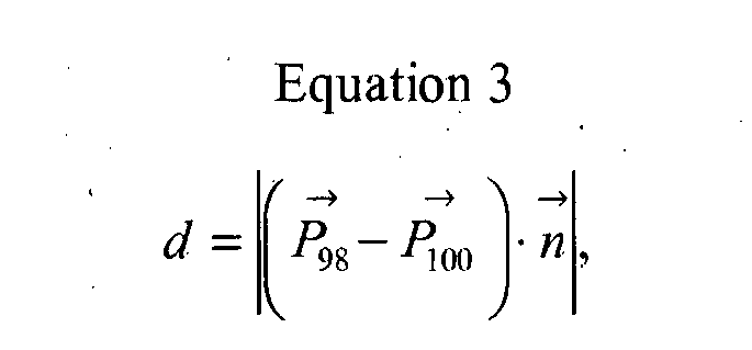
- d is the length of the line segment connecting the LORs 98 and 100:
- d P ⁇ 98 - P ⁇ 100 ⁇ n ⁇
- n is a unit vector pointing in the direction of the line segment connecting the LORs 98 and 100:
- n ⁇ : P ⁇ 98 ⁇ P ⁇ 100 / P ⁇ 98 ⁇ P ⁇ 100
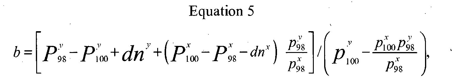
- b is defined by:
- b P 98 y - P 100 y + d ⁇ n y + P 100 y - P 98 y - d ⁇ n y ⁇ p 98 y p 98 x / p 100 y - p 100 x ⁇ p 98 y p x
- the vector analysis component 696 generates a collection of points ⁇ C1, C2, ... Cn ⁇ for n successive pairs of LORs, thereby generating a point cloud.
- the characteristic feature generator 280 determines the center or mass or other desired characteristic feature of the point cloud. If desired, outlying points may be disregarded when determining the center of mass.
- the motion determiner 282 again uses the characteristic feature data to generate the motion model P(t).
- the motion model P(t) may also be used by the reconstructors 110, 106 to compensate for motion in the reconstructed images.
- the motion model P(t) can be used to shift the positions of LORs indicative of events occurring in the ROI so as to compensate for the detected motion. All or a desired portion of the acquired data set is then reconstructed.
- the techniques described above may also be applied to acquisitions in which the projection data is sorted or binned into a plurality of bins.
- a plurality of sets of bins would be established, with each set corresponding to a desired time period or motion phase.
- the grouper 252 would then operate at the time of or in connection with the data acquisition to sort or bin the projection data into the appropriate bin as a function of its location or other characteristic(s) and a time at which a particular projection data was received.
- the techniques are also applicable to single photon emission tomography (SPECT) and other functional and structural modalities. They are also applicable to other treatment modalities.
- SPECT single photon emission tomography
- Lesions or other hot spots may also be blurred by motion of the object, with such blurring tending to reduce the average intensity of the hot spot.
- the reduction in intensity may in many cases lead to the non-identification of the hot spot or otherwise complicate its detection. Consequently, a motion correction may be applied to regions known to have or suspected of having one or more relatively weaker or unidentified hot spots. As the motion correction tends to intensify the relative weaker areas and thus aid in the identification of suspect regions, the motion corrected data may be analyzed to identify lesions or other features of interest.
- first and second agents and/or isotopes may be introduced in the object in connection with a given scan.
- the first agent is used to produce the desired study data, while the second is used to identify the desired motion.
- the second agent is selected for its affinity to a portion of the object in the vicinity of and which serves as a proxy for the motion of the ROI.
- 18-F can be used to identify a structure such as a rib or other bone which can serve as a proxy for respiratory motion.
- NH3 can be used to identify the myocardium in connection with cardiac motion.
- a first or motion ROI is established at the proxy region, with the motion corrector 116 operating on data from the motion ROI to generate the motion model P(t) as described above.
- the motion model P(t) is used in connection with the motion compensation of image data
- a second or imaging ROI is established at the region being studied. The motion model P(t) is then used to shift or otherwise correct the projection data to compensate for motion in the imaging ROI. Suitable techniques for such compensation are also described in the patent application incorporated by reference above.
- the motion model P(t) may be plotted and displayed on a display, printout, film or other suitable human readable output device.
- a plot or motion track of a feature or interest in connection with a given scan is shown in Figures 5A, 5B, 5C where an arbitrary motion of a feature of interest is shown projected into three planes such as planes parallel to the x, y, and z planes of the motion model P(t).
- the plot may also be presented in relation to a single arbitrarily selected plane or surface, with movement in other directions presented by changing a color, thickness, or other characteristic of the motion plot.
- the desired plot(s) may also be superimposed on corresponding image(s) of the object. Doing so may be particularly useful in situations where the motion of a feature of interest may not be readily apparent from the image itself, as may occur in the case of a motion compensated image or in the case of a non-motion compensated image which exhibits significant blurring.
- a superimposed image is illustrated in FIGURE 5D , where an arbitrary motion trajectory 404 is shown superimposed on motion compensated image of a feature of interest 402. While illustrated as being superimposed or overlayed on a relevant image, the motion may also be displayed in a separate window or in a distinct region of the display, adjacent the feature of interest, or the like.
- the feature of interest may include a lung tumor, while the motion trajectory depicts movement of the tumor due to respiratory motion.
Landscapes
- Health & Medical Sciences (AREA)
- Engineering & Computer Science (AREA)
- Life Sciences & Earth Sciences (AREA)
- Medical Informatics (AREA)
- Biomedical Technology (AREA)
- Pathology (AREA)
- Nuclear Medicine, Radiotherapy & Molecular Imaging (AREA)
- Radiology & Medical Imaging (AREA)
- Animal Behavior & Ethology (AREA)
- General Health & Medical Sciences (AREA)
- Public Health (AREA)
- Veterinary Medicine (AREA)
- Heart & Thoracic Surgery (AREA)
- Molecular Biology (AREA)
- Biophysics (AREA)
- High Energy & Nuclear Physics (AREA)
- Physics & Mathematics (AREA)
- Optics & Photonics (AREA)
- Surgery (AREA)
- Theoretical Computer Science (AREA)
- Pulmonology (AREA)
- Computer Vision & Pattern Recognition (AREA)
- Nuclear Medicine (AREA)
- Radiation-Therapy Devices (AREA)
- Apparatus For Radiation Diagnosis (AREA)
- Image Analysis (AREA)
Description
- The present application relates to motion estimation in treatment and treatment planning. While it finds particular application to the use of positron emission tomography (PET) data to estimate motion in connection with external radiotherapy in medicine, it also relates to other applications in which it is desirable to account for the effects of motion of an object.
-
US 2005/0226485 A1 discloses a rotation angiography device for angiocardiography. The rotation angiocardiography device comprises a radiation source attached to a C-arm, a detector and an evaluation unit which formulates models with low resolution from the projection images supplied by the detector for a moving object to be examined, and which generates movement fields for the projection images generated by the detector on the basis of the models. Movement-corrected projection images are calculated from the projection images based on the generated measurement fields, wherein the movement corrected projection images are used to formulate a three-dimensional high-resolution model of the object to be examined. -
US 2006/0074292 A1 discloses a method for dynamically tracking treatment targets such as tumors or lesions, located within an anatomical region that undergoes motion which may be periodic with cycle P. A four-dimensional mathematical model is established for a non-rigid motion and deformation of the anatomical region from a set of computed tomography or other three-dimensional images. The four-dimensional mathematical model relates three-dimensional locations of part(s) of the anatomical region with the targets being tracked as a function of the position in time within P. Using fiducial-less non-rigid image registration between pre-operative digitally reconstructed radiographs and intra-operative x-ray images, the absolute position of the target and/or other part(s) of the anatomical region is determined. The cycle P is determined using motion sensors such as surface markers. The radiation beams are delivered using: 1) the results of non-rigid image registration; 2) the four-dimensional model; and 3) the position in time within P. -
US 2004/0267113 A1 discloses a method and a system for treating moving target regions in a patient's anatomy by creating radiosurgical lesions. Computed tomography scan data representative of a pre-operational diagnostic image of a target region are generated, wherein based on the computed tomography scan data a treatment plan is generated that defines requisite beam intensities and paths. The position of the target region is determined in near real time and composite motion of the target region, due to respiration and heartbeat, is tracked. Signals representative of the change caused by the composite motion in the position of the target region at a current time, compared to the position of the target region in the computed tomography scan, are generated and, in response, the relative position of an x-ray source and the target is adjusted, so as to account for the composite motion of the target. This process is repeated throughout the treatment. As a result, the x-rays are continually focused onto the target region in accordance with the treatment plan, while the x-ray source tracks the motion of the target region. - The article "Precise and real-time measurement of 3D tumor motion in lung due to breathing and heartbeat, measured during radiotherapy" by Y. Seppenwoolde et al., International Journal of Radiation: Oncology, Biology, Physics, volume 53, pages 822-834 (2002) discloses a method for determining a three-dimensional tumor motion in the lung, which is caused by breathing and heartbeat, depending on at least two x-ray fluoroscopy images, which have been acquired in different directions.
- In "Radiotherapy and Oncology", volume 81, pages 212 and 213, ISSN: 0167-8140, Elsevier (2006) it is disclosed to acquire positron emission tomography projection data, which are correlated to a respiration signal, wherein respiration correlated positron emission tomography images are reconstructed based on the respiration correlated positron emission tomography projection data.
- The article "Quantative Reconstruction from Truncated Projections" by R. Clackdoyle et al., IEEE Nuclear Science Symposium Conference, ISBN: 978-0-7803-8257-2, volume 3, pages 2036-2038 (2003) discloses a method for reconstructing an image of a region of interest from truncated projections.
-
US 2005/0249432 A1 discloses a method for reconstructing an image of a region of interest of an object based on chords which may fill a part of the region of interest. - In medical applications, structural medical imaging modalities such as computed tomography (CT) and magnetic resonance (MR) are widely used to generate image data indicative of the internal morphology of a patient. One application for this data is radiation therapy planning (RTP) in oncology, in which the image data has been used to calculate a spatially varying radiation dose to be applied to a tumor or other lesion. The calculated dose has been applied to the patient using therapy techniques such as intensity modulated radiotherapy (IMRT). These techniques have been used to more closely tailor the treatment to the requirements of a particular situation, for example, to apply a relatively higher dose to a desired portion of a tumor and reduce the effects of the treatment on surrounding healthy tissue.
- A more recent trend has been the use of functional information in therapy planning. Information from a functional imaging modality such as positron emission tomography (PET) provides information indicative of the functional characteristics of a tumor, and more particularly the spatial variation of a functional characteristic. This information can in turn be used to better identify regions of the tumor where an increased dose should be applied, or stated conversely, may be treated with a relatively lower dose. As one example, current research indicates that hypoxic tissues within a tumor may be relatively resistant to treatment. It is thus desirable to apply a relatively higher dose to regions of the tumor that contain such tissues.
- However, the target volume can be affected by patient motion, as for example periodic respiratory motion. To compensate for the effects of such motion, and to ensure that the desired clinical target volume receives the desired dose, a planning margin has been established, with the dose applied to the relatively larger volume.
- Unfortunately, however, such an approach can be injurious to otherwise healthy tissue.
- Moreover, such motion also tends to reduce the accuracy with which a spatially varying dose can be applied to the desired regions of the tumor.
- Aspects of the present application address these matters and others.
- In accordance with one aspect, a method for generating a motion estimation usable by a treatment apparatus includes correlating functional projection data acquired during an examination of an object with a measured motion of the object; filtering the correlated projection data to select projection data which does intersect a first region of interest of the object; using the filtered correlated projection data to model a time varying feature of the first region of interest of the object, wherein a vector analysis is performed on the filtered projection data for generating a collection of points, thereby generating a point cloud, wherein a characteristic feature of the point cloud is determined and wherein the determined characteristic feature is used for generating a motion model.
- It is preferred that the model models a motion of the characteristic feature.
- It is further preferred that the characteristic feature is a center of activity.
- In an embodiment, the method includes displaying a trajectory of the time varying feature in a human readable form.
- It is preferred that the motion is a respiratory motion and the region of interest includes a tumor.
- According to another aspect, a computer readable storage medium contains instructions which, when executed by a computer, cause the computer to carry out a method which includes:
- correlating functional projection data acquired during an examination of an object with a measured motion of the object;
- filtering the correlated projection data to select projection data which does intersect a first region of interest of the obj ect;
- using the filtered correlated projection data to model a time varying feature of the first region of interest of the object, wherein a vector analysis is performed on the filtered projection data for generating a collection of points, thereby generating a point cloud, wherein a characteristic feature of the point cloud is determined and wherein the determined characteristic feature is used for generating a motion model,
- supplying the model to a treatment apparatus that applies a treatment to the object.
- According to another aspect, an apparatus includes a grouper, a filter, a characteristic processor, and a position determiner. The grouper groups functional projection data indicative of an interior of an object according to a motion of the object measured during the acquisition of the projection data. The filter selects projection data that is indicative of a first region of interest of the object. The characteristic processor uses the selected projection data to identify a characteristic feature of the first region of interest. The characteristic processor includes a vector analysis component and a characteristic feature generator. The vector analysis component receives the selected projection data and performs a vector analysis on the selected projection data for generating a collection of points, thereby generating a point cloud. The characteristic feature generator identifies the characteristic feature by determining a characteristic feature of the point cloud. The position determiner determines a position of the identified feature as a function of the measured motion.
- It is preferred that the apparatus includes a hybrid modality scanner that generates the projection data.
- It is further preferred that the apparatus includes an external radiotherapy 15 apparatus that modulates a therapy applied to the object as a function of the determined position and a motion of the object measured during the application of the therapy.
- In an embodiment, the measured motion is a physiological motion and the projection data includes time of flight positron emission tomography data.
- It is preferred that the apparatus includes a reconstructor that generates motion corrected image data indicative of the region of interest.
- It is further preferred that the apparatus includes means for displaying a motion of the identified feature.
- In an embodiment, the apparatus includes a computer processor which executes computer readable instruction which cause the processor to perform the functions of the grouper, the filter, the characteristic processor, and the position determiner.
- According to another aspect, a computer readable storage medium contains instructions which, when executed by a computer, cause the computer to carry out a method. The method includes grouping projection data indicative of radionuclide decays in an object according to a motion of the object, selecting projection data that is indicative of radionuclide decays occurring in a first region of interest of the object, using the selected projection data to identify a characteristic feature of the first region of interest, and using the grouped projection data to determine a position of the identified feature as a function of the motion.
- It is preferred that the determined position of the first region of interest serves as a proxy for a position of a second region of interest.
- It is further preferred that the method includes plotting a trajectory of the determined position on an image which includes the region of interest.
- In an embodiment, the method includes storing the determined position in a computer readable memory accessible to a treatment apparatus.
- Still further aspects of the present invention will be appreciated to those of ordinary skill in the art upon reading and understand the following detailed description.
- The invention may take form in various components and arrangements of components, and in various steps and arrangements of steps. The drawings are only for purposes of illustrating the preferred embodiments and are not to be construed as limiting the invention.
-
FIGURE 1 is a block diagram of a diagnosis and treatment system. -
FIGURE 2 is a block diagram of a motion modeler. -
FIGURE 3 depicts intermediate images. -
FIGURE 4 depicts aspects of a technique for generating intermediate images. -
FIGURES 5A-D depict motion trajectories. -
FIGURE 6 is a block diagram of a motion modeler. -
FIGURE 7 depicts vectors. - With reference to
FIGURE 1 , asystem 100 includes a functionalimaging modality scanner 102, a structuralimaging modality scanner 104, amotion monitor 100, ascanning motion modeler 116, and atreatment planner 112. - As illustrated in
FIGURE1 , the functionalimaging modality scanner 102 is a PET scanner. PET scanners conventionally include a plurality of radiationsensitive detectors 118 disposed about anexamination region 120 in a generally ring or cylindrically shaped arrangement. In connection with a PET examination, a tracer which includes a positron emitting radionuclide is introduced into the object under examination. As the radionuclide decays, the emitted positrons interact with electrons in what are known as positron annihilations, with the annihilations generating pairs of temporally coincident 511 kiloelectron volt (keV) gamma rays which travel in substantially opposite directions along a line of response (LOR) 122. Where theimager 102 is a time of flight (TOF) PET scanner, a time of flight detector measures the arrival times of the coincident photons, with the resultant information being used to estimate the position of the annihilation along theLOR 122. - The
functional imaging scanner 102 generates raw or projection data indicative of the detected annihilations. In the case of a list mode acquisition, the raw data includes a list of the many annihilations detected in the course of a given scan, with the entries in the list typically contain information indicative of the location and orientation of theLOR 122, the location of the event along the LOR 122 (particularly in the case of a TOF system), the time at which the annihilation was detected, and other relevant information. - A
reconstructor 110 reconstructs the raw data using a suitable iterative, analytical, or other reconstruction technique to generate volumetric image data indicative of the object. - The structural
imaging modality scanner 104 includes a CT, MR, or other scanner which generates projection data indicative of the structure of the object. Areconstructor 106 reconstructs the raw data to produce volumetric image data indicative of the object using reconstruction techniques which are appropriate for thescanner 104 modality. - Note that the functional 102 and structural 104 imaging modality scanners may be combined in a single scanner, for example in the case of a PET/CT, PET/MR or other hybrid modality scanner.
- The
scanning motion monitor 100, which measures a motion of the object in connection with a scan, operates in conjunction with the functional 102 and/or structural 104 scanners so that projection data acquired during the course of a given scan can be correlated with the motion state of the object. It will be appreciated that the form and function of the scanning motion monitor 100 depends on the object being monitored and the nature of the monitored motion. Themonitor 100 may measure the motion indirectly, for example by way of one or more mechanical, electrical, or other sensors that sense dynamic or time varying features indicative of the motion of interest. In the case of a human patient, for example, themotion monitor 100 may include a physiological monitor which measures physiological signal(s) indicative of a physiological motion of interest. A respiratory monitor, for example, may include a chest belt or other device which senses the periodic mechanical motion associated with breathing, a temperature sensor which measures the temperature of the patient's respiratory air, or the like. In the case of cardiac motion, themotion monitor 100 may measure an electrocardiogram (ECG) signal. - As will be described further below, the
motion modeler 116 uses projection data from thefunctional scanner 102 and the information from themotion monitor 100 to generate a local motion model representative of a region of interest of the object. Where the motion is modeled in three spatial dimensions, the motion model can be expressed according to the relation:
- The
treatment planner 112 uses the image data from the functional 102 and/orstructural scanners 104 to plan a treatment to be applied to the object. In the case of an RTP system used in radiation oncology, the treatment plan typically includes a spatially varying radiation dose which is to be applied to a tumor or other lesion. - With continuing reference to
FIGURE 1 , thesystem 100 also includes atreatment device 114 and atreatment motion monitor 108. - The
treatment motion monitor 108 is analogous to thescanning motion monitor 100, with its nature and configuration again depending on the nature of the object and the motion being monitored. Note that thescanning 100 andtreatment 108 motion monitors may be implemented as a single device, for example where a single motion monitor is transported from location to location or where one or more of thescanners treatment device 114 are located in physical proximity. - The
treatment device 114 applies the desired treatment to the object. More specifically, the object is typically positioned in a known position and orientation with respect to thetreatment device 114. Depending again on the object to be treated and the nature of the treatment, such positioning may be facilitated, by way of fiducial markers, positioning devices which conform to a portion of the object (e.g., a conformal face mask in the case of a therapy to be applied to the head of a human patient), other restraints, auxiliary imaging devices which provide structural or other image data, or other suitable techniques. Thetreatment device 114 uses motion information from the motion model P(t) and thetreatment motion monitor 108 to compensate for object motion during the course of the applied treatment. In the case of respiratory motion of a human patient, for example, thetreatment device 114 would ordinarily compensate for the patient's respiratory phase. - As illustrated in
FIGURE 1 , thetreatment device 114 includes amodulator 121 which modulates an intensity or other characteristic of the treatment applied to the object, for example by modulating a spatial, temporal, and/or other characteristic of the applied dose so that the applied treatment approximates that calculated bytreatment planner 112. Again in relation to the example of external radiation therapy in oncology, thetreatment device 114 may include an intensity modulated radiation therapy device. Such devices typically include a multi-leaf collimator which is used to modulate the applied radiation so as to apply the desired radiation dose to the tumor. Other treatment devices, including but not limited to linear accelerators, particle therapy devices, radio frequency ablation or other devices, and high field ultrasound treatment devices are also contemplated. - Turning now to
FIGURE 2 , themotion modeler 116 includes agrouper 252, afilter 254, acharacteristic processor 258, and aposition determiner 282. Thegrouper 252 groups the projection data from thefunctional scanner 102 into temporally corresponding groups. Where the data includes list mode PET data, for example, thegrouper 252 groups the various LORs into the appropriate temporal groups. - Note that, in the case of periodic motion, the motion period may be divided into a plurality of motion phases, with the projection data grouped according to the motion phase in which it was acquired. The temporal extent of the various groups may be, but is not necessarily, constant. Thus, groups which correspond to motion phases which are expected to exhibit relatively faster motion have a relatively shorter temporal duration. As another example, the motion phases may be grouped so that the number or amount or LORs or other projection data in each group is substantially constant. It will be appreciated, however, that other grouping schemes may also be implemented.
- The
filter 254 filters or disregards projection data that does not intersect (or stated conversely, selects projection data which does intersect) a user or automatically defined region of interest (ROI). Again in example of PET data in an oncology application, for example, thefilter 254 selects those LORs which intersect an ROI which includes a tumor of interest. Where TOF data is available, those LORs for which the annihilation likely falls outside the ROI may be discarded. - A
characteristic processor 258 determines a characteristic feature such as a center of mass or other center function of the projection data of each filtered group. As shown in the example ofFIGURE 2 , acontroller 260 of thecharacteristic processor 258 accesses asimplified reconstruction system 243. Thesimplified reconstructor 243 performs a locally constrained backprojection of the various groups of filtered projection data to generate partial images corresponding to the temporal groups. The partial images are stored in astorage component 278 such as a memory. -
FIGURE 3 depicts one example of anROI 356 and a plurality ofintermediate images 3621-10 generated by thesimplified reconstructor 243. In the example ofFIGURE 3 , a tumor 320 undergoes a generally circular, clockwise motion in theROI 356. While ten (10)intermediate images 362 are shown inFIGURE 3 for the purposes of illustration, other numbers of temporal groups and/or intermediate images may also be generated. It will also be appreciated thatFIGURE 3 depicts an image slice of theROI 356. Where theROI 356 includes a volume, the reconstructed intermediate image data covering the volume would be reconstructed. - In one implementation, the distance over which the various projections intersect the voxels of the
ROI 256 is calculated, with thesimplified reconstructor 243 updating the voxel values as a function of the calculated distance. In a simplified implementation, the value of a given voxel is incremented or otherwise increased uniformly each time a projection intersects the voxel. This is illustrated inFIGURE 4 again in the example case of a PET system where anLOR 264 intersectsvoxels ROI 256. Note that the voxel weighting produced by thesimplified reconstructor 243 may also take into account TOF data, if available. - Returning to
FIGURE 2 , acharacteristic feature generator 280 computes a center of mass, center of activity, or other characteristic feature of the various partial images. Depending on the selected simplified reconstruction technique, and to reduce the effects of projection data indicative of regions outside theROI 256, it may be desirable to consider only a subset of the voxels in the ROI when calculating the characteristic feature. This may be accomplished, for example, by way of a thresholding technique in which those voxels having a value less than a user selected or other desired percentage of the maximum voxel value of the ROI are not considered. - The
motion determiner 282 uses the characteristic feature data to generate the motion model P(t), with the motion model being stored in a computer readable memory accessible to or otherwise provided to thetreatment device 114. -
FIGURE 6 depicts an alternative embodiment of themotion modeler 116, with like reference numerals describing items analogous to those described above in relation toFIGURE 2 . - As illustrated, the
characteristic processor 258 includes avector analysis component 696 which receives the filtered projection data generated by thefilter 254. Again in the context of LORs generated in PET imaging, it will be assumed that each LOR can be described by a pointP x on the LOR and a unit vectorp x which describes its direction.FIGURE 7 illustrates two such LORs, with afirst LOR 98 described by pointP 98 and unit vectorp 98 and asecond LOR 100 described by pointP 100 and unit vectorp 100. - Point
C represents the center of theshortest line segment 102 connecting the first 98 and second 100 LORs:

- Returning to
FIGURE 6 , thevector analysis component 696 generates a collection of points {C1, C2, ... Cn} for n successive pairs of LORs, thereby generating a point cloud. - Note that parallel LORs or LORs perpendicular to the x-axis are treated separately.
- The
characteristic feature generator 280 determines the center or mass or other desired characteristic feature of the point cloud. If desired, outlying points may be disregarded when determining the center of mass. Themotion determiner 282 again uses the characteristic feature data to generate the motion model P(t). - Suitable techniques for determining a motion of a region of interest are also disclosed in commonly owned
U.S. Provisional Patent Application Serial Number 60/777,469 filed on February 28, 2006 reconstructors - The techniques described above may also be applied to acquisitions in which the projection data is sorted or binned into a plurality of bins. In such an implementation, a plurality of sets of bins would be established, with each set corresponding to a desired time period or motion phase. The
grouper 252 would then operate at the time of or in connection with the data acquisition to sort or bin the projection data into the appropriate bin as a function of its location or other characteristic(s) and a time at which a particular projection data was received. - The techniques are also applicable to single photon emission tomography (SPECT) and other functional and structural modalities. They are also applicable to other treatment modalities.
- There may be situations in which it is relatively difficult to effectively identify a specific lesion or other feature of the object in order to establish the motion model. Such a situation may arise, for example, in relatively specific, low intensity PET studies involving the use of labeled monoclonal antibodies, stem cell monitoring, or other molecular imaging techniques which produce relatively few low intensity hot spots and limited, if any, anatomical references.
- Lesions or other hot spots may also be blurred by motion of the object, with such blurring tending to reduce the average intensity of the hot spot. The reduction in intensity may in many cases lead to the non-identification of the hot spot or otherwise complicate its detection. Consequently, a motion correction may be applied to regions known to have or suspected of having one or more relatively weaker or unidentified hot spots. As the motion correction tends to intensify the relative weaker areas and thus aid in the identification of suspect regions, the motion corrected data may be analyzed to identify lesions or other features of interest.
- Multiple agents may also be used. For example, first and second agents and/or isotopes may be introduced in the object in connection with a given scan. The first agent is used to produce the desired study data, while the second is used to identify the desired motion. More particularly, the second agent is selected for its affinity to a portion of the object in the vicinity of and which serves as a proxy for the motion of the ROI. In one such example, 18-F can be used to identify a structure such as a rib or other bone which can serve as a proxy for respiratory motion. In another, NH3 can be used to identify the myocardium in connection with cardiac motion.
- In such an implementation, a first or motion ROI is established at the proxy region, with the
motion corrector 116 operating on data from the motion ROI to generate the motion model P(t) as described above. Where the motion model P(t) is used in connection with the motion compensation of image data, a second or imaging ROI is established at the region being studied. The motion model P(t) is then used to shift or otherwise correct the projection data to compensate for motion in the imaging ROI. Suitable techniques for such compensation are also described in the patent application incorporated by reference above. - It may also be desirable to provide a clinician or other user with a graphical representation of the motion of a lesion or other feature of interest. Accordingly, the motion model P(t) may be plotted and displayed on a display, printout, film or other suitable human readable output device. One example of such a plot or motion track of a feature or interest in connection with a given scan is shown in
Figures 5A, 5B, 5C where an arbitrary motion of a feature of interest is shown projected into three planes such as planes parallel to the x, y, and z planes of the motion model P(t). The plot may also be presented in relation to a single arbitrarily selected plane or surface, with movement in other directions presented by changing a color, thickness, or other characteristic of the motion plot. - The desired plot(s) may also be superimposed on corresponding image(s) of the object. Doing so may be particularly useful in situations where the motion of a feature of interest may not be readily apparent from the image itself, as may occur in the case of a motion compensated image or in the case of a non-motion compensated image which exhibits significant blurring. Such a superimposed image is illustrated in
FIGURE 5D , where anarbitrary motion trajectory 404 is shown superimposed on motion compensated image of a feature ofinterest 402. While illustrated as being superimposed or overlayed on a relevant image, the motion may also be displayed in a separate window or in a distinct region of the display, adjacent the feature of interest, or the like. By way of one example, the feature of interest may include a lung tumor, while the motion trajectory depicts movement of the tumor due to respiratory motion. - Note that the various techniques described above may be implemented by way of computer readable instructions stored on suitable computer readable media. When executed by a computer processor, the instructions cause the computer processor to carry out the described techniques.
- The invention has been described with reference to the preferred embodiments. Modifications and alterations may occur to others upon reading and understanding the preceding detailed description. It is intended that the invention be construed as including all such modifications and alterations insofar as they come within the scope of the appended claims.
Claims (11)
- A method for generating a motion estimation usable by a treatment apparatus, the method comprising:correlating functional projection data acquired during an examination of an object with a measured motion of the object;filtering the correlated projection data to select projection data which does intersect a first region of interest of the object;using the filtered correlated projection data to model a time varying feature of the first region of interest of the object, wherein a vector analysis is performed on the filtered projection data for generating a collection of points ({C1, C2, ..., Cn}), thereby generating a point cloud, wherein a characteristic feature of the point cloud is determined and wherein the determined characteristic feature is used for generating a motion model (P(t));supplying the model (P(t)) to a treatment apparatus adapted to apply a treatment to the object.
- The method of claim 1 wherein the motion is periodic and the method includes grouping the projection data according to a phase of the motion during which the projection data was acquired.
- The method of claim 1 including identifying a second region of interest which serves as a proxy for the motion of the first region of interest, wherein using includes using correlated projection data indicative of a characteristic feature of the second region of interest to model the motion of the first region of interest.
- The method of claim 1 wherein the method includes
generating a motion corrected image of a region which includes the first region of interest;
prior to the step of using the correlated projection data to model a time varying feature of the first region of interest, using the motion corrected image to identify the first region of interest. - The method of claim 1 wherein the projection data includes list mode data indicative of radionuclide decays in the object.
- The method of claim 1, the method further comprising:identifying a second region of the object;using the characteristic feature to correct projection data indicative of the second region to compensate for a motion of the second region;using the corrected projection data to reconstruct a motion-corrected image of the second region.
- An apparatus comprising:a grouper (252) that is configured to group functional projection data indicative of an interior of an object according to a motion of the object measured during the acquisition of the projection data;a filter (254) that is configured to select projection data that is indicative of a first region of interest of the object;a characteristic processor (248) that is configured to use the selected projection data to identify a characteristic feature of the first region of interest, wherein the characteristic processor (248) includes:a vector analysis component (696) being adapted to receive the selected projection data and to perform a vector analysis on the selected projection data for generating a collection of points ({C1, C2, ..., Cn}), thereby generating a point cloud; anda characteristic feature generator (280) being adapted to identify the characteristic feature by determining a characteristic feature of the point cloud;a position determiner (282) that is configured to determine a position of the identified feature as a function of the measured motion.
- The apparatus of claim 7 including a hybrid modality scanner (102, 104) that is configured to generate the projection data.
- The apparatus of claim 7 including an external radiotherapy apparatus (114) that is configured to modulate a therapy applied to the object as a function of the determined position and a motion of the object measured during the application of the therapy.
- The apparatus of claim 7 including a reconstructor (110, 106) that is configured to generate motion corrected image data indicative of the first region of interest.
- A computer readable storage medium containing instructions which, when executed by a computer, cause the computer to carry out a method which includes:correlating functional projection data acquired during an examination of an object with a measured motion of the object;filtering the correlated projection data to select projection data which does intersect a first region of interest of the object;using the filtered correlated projection data to model a time varying feature of the first region of interest of the object, wherein a vector analysis is performed on the filtered projection data for generating a collection of points ({C1, C2, ..., Cn}), thereby generating a point cloud, wherein a characteristic feature of the point cloud is determined and wherein the determined characteristic feature is used for generating a motion model (P(t));supplying the model (P(t)) to a treatment apparatus that applies a treatment to the object.
Applications Claiming Priority (2)
| Application Number | Priority Date | Filing Date | Title |
|---|---|---|---|
| US88856007P | 2007-02-07 | 2007-02-07 | |
| PCT/IB2008/050279 WO2008096285A2 (en) | 2007-02-07 | 2008-01-25 | Motion estimation in treatment planning |
Publications (2)
| Publication Number | Publication Date |
|---|---|
| EP2109399A2 EP2109399A2 (en) | 2009-10-21 |
| EP2109399B1 true EP2109399B1 (en) | 2014-03-12 |
Family
ID=39560928
Family Applications (1)
| Application Number | Title | Priority Date | Filing Date |
|---|---|---|---|
| EP08702527.6A Not-in-force EP2109399B1 (en) | 2007-02-07 | 2008-01-25 | Motion estimation in treatment planning |
Country Status (5)
| Country | Link |
|---|---|
| US (1) | US8351571B2 (en) |
| EP (1) | EP2109399B1 (en) |
| JP (1) | JP2010517655A (en) |
| CN (1) | CN101610719B (en) |
| WO (1) | WO2008096285A2 (en) |
Families Citing this family (56)
| Publication number | Priority date | Publication date | Assignee | Title |
|---|---|---|---|---|
| EP2109399B1 (en) * | 2007-02-07 | 2014-03-12 | Koninklijke Philips N.V. | Motion estimation in treatment planning |
| JP2010517672A (en) * | 2007-02-07 | 2010-05-27 | コーニンクレッカ フィリップス エレクトロニクス エヌ ヴィ | Motion compensation and treatment of quantitative data analysis |
| US8017915B2 (en) | 2008-03-14 | 2011-09-13 | Reflexion Medical, Inc. | Method and apparatus for emission guided radiation therapy |
| WO2010110255A1 (en) * | 2009-03-24 | 2010-09-30 | 国立大学法人北海道大学 | Radiation therapy apparatus |
| WO2011070465A2 (en) * | 2009-12-10 | 2011-06-16 | Koninklijke Philips Electronics, N.V. | Method and apparatus for using time of flight information to detect and correct for motion in imaging scans |
| US20110319741A1 (en) * | 2010-06-23 | 2011-12-29 | Elekta Ab (Publ) | Adapting radiotherapy treatment plans |
| CN103080977B (en) * | 2010-08-25 | 2016-01-06 | 皇家飞利浦电子股份有限公司 | Launching the location of the heart in image and checking |
| RU2013136488A (en) * | 2011-01-05 | 2015-02-10 | Конинклейке Филипс Электроникс Н.В. | METHOD AND DEVICE FOR MOTION DETECTION AND CORRECTION IN POSITRON-EMISSION TOMOGRAPHY DATA IN THE LIST MODE USING A SYNCHRONIZED SIGNAL |
| JP6210972B2 (en) | 2011-03-31 | 2017-10-11 | リフレクション メディカル, インコーポレイテッド | System and method for use in radiation induced radiation therapy |
| WO2012159123A2 (en) | 2011-05-19 | 2012-11-22 | Alec Rivers | Automatically guided tools |
| US20130035588A1 (en) * | 2011-08-03 | 2013-02-07 | Siemens Corporation | Magnetic resonance imaging for therapy planning |
| CN103126701B (en) * | 2011-11-30 | 2016-04-27 | 株式会社东芝 | Positron emission tomography device and image processing apparatus |
| CN110075426A (en) * | 2011-11-30 | 2019-08-02 | 皇家飞利浦有限公司 | The automatic algorithms and framework of plan access are disposed for patients more in radiation therapy |
| US10556356B2 (en) | 2012-04-26 | 2020-02-11 | Sharper Tools, Inc. | Systems and methods for performing a task on a material, or locating the position of a device relative to the surface of the material |
| NL2010267C2 (en) * | 2013-02-07 | 2014-08-11 | Milabs B V | High energy radiation detecting apparatus and method. |
| EP3061495B1 (en) * | 2013-10-24 | 2018-07-25 | Hitachi, Ltd. | Control device for treatment planning device, control method, and program |
| US10675487B2 (en) | 2013-12-20 | 2020-06-09 | Mevion Medical Systems, Inc. | Energy degrader enabling high-speed energy switching |
| US9962560B2 (en) | 2013-12-20 | 2018-05-08 | Mevion Medical Systems, Inc. | Collimator and energy degrader |
| KR102238693B1 (en) | 2014-06-20 | 2021-04-09 | 삼성전자주식회사 | Method and apparatus for extracting feature regions in point cloud |
| US10499992B2 (en) * | 2014-10-30 | 2019-12-10 | Edda Technology, Inc. | Method and system for estimating a deflated lung shape for video assisted thoracic surgery in augmented and mixed reality |
| US20160217588A1 (en) | 2014-12-11 | 2016-07-28 | Jeffrey R. Hay | Method of Adaptive Array Comparison for the Detection and Characterization of Periodic Motion |
| US10062411B2 (en) | 2014-12-11 | 2018-08-28 | Jeffrey R. Hay | Apparatus and method for visualizing periodic motions in mechanical components |
| US12300273B2 (en) | 2014-12-11 | 2025-05-13 | Rdi Technologies, Inc. | Apparatus and method for visualizing periodic motions in mechanical components |
| US9878177B2 (en) | 2015-01-28 | 2018-01-30 | Elekta Ab (Publ) | Three dimensional localization and tracking for adaptive radiation therapy |
| WO2016183390A1 (en) | 2015-05-13 | 2016-11-17 | Taktia Llc | Systems, methods and apparatus for guided tools |
| US10255684B2 (en) * | 2015-06-05 | 2019-04-09 | University Of Tennessee Research Foundation | Motion correction for PET medical imaging based on tracking of annihilation photons |
| CN107924730B (en) | 2015-06-10 | 2021-09-28 | 反射医疗公司 | High bandwidth binary multileaf collimator design |
| JP6980535B2 (en) * | 2015-07-09 | 2021-12-15 | コーニンクレッカ フィリップス エヌ ヴェKoninklijke Philips N.V. | Radiation therapy system using multiple treatment plans |
| US10786689B2 (en) | 2015-11-10 | 2020-09-29 | Mevion Medical Systems, Inc. | Adaptive aperture |
| CN109152928B (en) | 2016-03-09 | 2021-05-28 | 反射医疗公司 | Method and system for calculating a fluence map for radiation therapy |
| EP3906968A1 (en) | 2016-07-08 | 2021-11-10 | Mevion Medical Systems, Inc. | Treatment planning |
| US11308662B2 (en) | 2016-08-02 | 2022-04-19 | Shanghai United Imaging Healthcare Co., Ltd. | System and method for image reconstruction |
| US10347014B2 (en) | 2016-08-02 | 2019-07-09 | Shanghai United Imaging Healthcare Co., Ltd. | System and method for image reconstruction |
| WO2018023380A1 (en) * | 2016-08-02 | 2018-02-08 | 上海联影医疗科技有限公司 | Method and system for image reconstruction |
| WO2018035499A2 (en) | 2016-08-19 | 2018-02-22 | Shaper Tools, Inc. | Systems, methods and apparatus for sharing tool fabrication and design data |
| JP7178714B2 (en) | 2016-11-15 | 2022-11-28 | リフレクション メディカル, インコーポレイテッド | Radiation Therapy Patient Platform |
| WO2018093849A1 (en) | 2016-11-15 | 2018-05-24 | Reflexion Medical, Inc. | Methods for radiation delivery in emission-guided radiotherapy |
| JP7201243B2 (en) | 2016-11-15 | 2023-01-10 | リフレクション メディカル, インコーポレイテッド | System for Stimulated Emission High-Energy Photon Delivery |
| US11103730B2 (en) | 2017-02-23 | 2021-08-31 | Mevion Medical Systems, Inc. | Automated treatment in particle therapy |
| WO2018183748A1 (en) | 2017-03-30 | 2018-10-04 | Reflexion Medical, Inc. | Radiation therapy systems and methods with tumor tracking |
| US10653892B2 (en) | 2017-06-30 | 2020-05-19 | Mevion Medical Systems, Inc. | Configurable collimator controlled using linear motors |
| JP7672126B2 (en) | 2017-07-11 | 2025-05-07 | リフレクション メディカル, インコーポレイテッド | Method for PET detector afterglow management - Patents.com |
| EP3664712B1 (en) | 2017-08-09 | 2025-03-12 | RefleXion Medical, Inc. | Systems and methods for fault detection in emission-guided radiotherapy |
| US11369806B2 (en) | 2017-11-14 | 2022-06-28 | Reflexion Medical, Inc. | Systems and methods for patient monitoring for radiotherapy |
| EP3710110A1 (en) | 2017-11-16 | 2020-09-23 | Ebamed SA | Heart arrhythmia non-invasive treatment device and method |
| CN119701229A (en) | 2018-02-13 | 2025-03-28 | 反射医疗公司 | Beam station treatment planning and radiation delivery method |
| CN108634974B (en) * | 2018-04-03 | 2022-03-04 | 东软医疗系统股份有限公司 | A method and device for determining a gating signal |
| US11423551B1 (en) | 2018-10-17 | 2022-08-23 | Rdi Technologies, Inc. | Enhanced presentation methods for visualizing motion of physical structures and machinery |
| WO2021094824A1 (en) | 2019-11-14 | 2021-05-20 | Ebamed Sa | Cardiac phase gating system for radiation therapy |
| US11373317B1 (en) | 2020-01-24 | 2022-06-28 | Rdi Technologies, Inc. | Measuring the speed of rotation or reciprocation of a mechanical component using one or more cameras |
| EP3896641A1 (en) * | 2020-04-16 | 2021-10-20 | Siemens Healthcare GmbH | Correcting object movement during mr imaging |
| CN111462168B (en) * | 2020-04-22 | 2023-09-19 | 上海联影医疗科技股份有限公司 | Motion parameter estimation method and motion artifact correction method |
| US11282213B1 (en) | 2020-06-24 | 2022-03-22 | Rdi Technologies, Inc. | Enhanced analysis techniques using composite frequency spectrum data |
| EP4192576A4 (en) | 2020-08-07 | 2024-08-28 | RefleXion Medical Inc. | MULTI-SENSOR GUIDED RADIOTHERAPY |
| US11322182B1 (en) | 2020-09-28 | 2022-05-03 | Rdi Technologies, Inc. | Enhanced visualization techniques using reconstructed time waveforms |
| WO2022136925A1 (en) | 2020-12-23 | 2022-06-30 | Ebamed Sa | A multiplanar motion management system |
Citations (1)
| Publication number | Priority date | Publication date | Assignee | Title |
|---|---|---|---|---|
| US20050249432A1 (en) * | 2004-02-10 | 2005-11-10 | Yu Zou | Imaging system |
Family Cites Families (17)
| Publication number | Priority date | Publication date | Assignee | Title |
|---|---|---|---|---|
| US6076005A (en) | 1998-02-25 | 2000-06-13 | St. Jude Children's Research Hospital | Respiration responsive gating means and apparatus and methods using the same |
| ATE324930T1 (en) * | 1998-08-06 | 2006-06-15 | Wisconsin Alumni Res Found | SYSTEM FOR ADJUSTING RADIATION DELIVERY FOR RADIATION THERAPY |
| US6144875A (en) * | 1999-03-16 | 2000-11-07 | Accuray Incorporated | Apparatus and method for compensating for respiratory and patient motion during treatment |
| US6473636B1 (en) | 2000-02-03 | 2002-10-29 | Siemens Corporate Research, Inc. | Variable-length correlation method for motion correction in SPECT myocardial perfusion imaging |
| WO2004033041A1 (en) * | 2002-10-07 | 2004-04-22 | Nomos Corporation | Method and apparatus for target position verification |
| DE10251448A1 (en) * | 2002-11-05 | 2004-05-19 | Siemens Ag | CT method for imaging of a periodically moving examination area, especially the heart, whereby image segments are combined to form image planes, which are subsequently joined together to form a complete image |
| US7171257B2 (en) * | 2003-06-11 | 2007-01-30 | Accuray Incorporated | Apparatus and method for radiosurgery |
| US7778691B2 (en) | 2003-06-13 | 2010-08-17 | Wisconsin Alumni Research Foundation | Apparatus and method using synchronized breathing to treat tissue subject to respiratory motion |
| US7140057B2 (en) | 2003-07-28 | 2006-11-28 | Aspen Seating, Llc | Reinforced and adjustable contoured seat cushion and method of reinforcing and adjusting the contoured seat cushion |
| JP3863873B2 (en) | 2003-09-30 | 2006-12-27 | 株式会社日立製作所 | Radiation inspection equipment |
| US10342558B2 (en) * | 2003-09-30 | 2019-07-09 | Koninklijke Philips N.V. | Target tracking method and apparatus for radiation treatment planning and delivery |
| DE102004017478B4 (en) * | 2004-04-08 | 2012-01-19 | Siemens Ag | Device for obtaining structural data of a moving object |
| US8989349B2 (en) | 2004-09-30 | 2015-03-24 | Accuray, Inc. | Dynamic tracking of moving targets |
| US8027715B2 (en) * | 2004-10-02 | 2011-09-27 | Accuray Incorporated | Non-linear correlation models for internal target movement |
| DE102005000714A1 (en) | 2005-01-03 | 2006-07-20 | Siemens Ag | Medical imaging method for imaging a periodically moving object area, e.g. heart or lungs, by recording of general object area image data, addition of markers, subsequent periodic imaging and then interpolation of marker positions |
| US7453983B2 (en) | 2005-01-20 | 2008-11-18 | Carestream Health, Inc. | Radiation therapy method with target detection |
| EP2109399B1 (en) * | 2007-02-07 | 2014-03-12 | Koninklijke Philips N.V. | Motion estimation in treatment planning |
-
2008
- 2008-01-25 EP EP08702527.6A patent/EP2109399B1/en not_active Not-in-force
- 2008-01-25 JP JP2009548771A patent/JP2010517655A/en not_active Withdrawn
- 2008-01-25 WO PCT/IB2008/050279 patent/WO2008096285A2/en not_active Ceased
- 2008-01-25 CN CN200880004314.1A patent/CN101610719B/en not_active Expired - Fee Related
- 2008-01-25 US US12/525,825 patent/US8351571B2/en not_active Expired - Fee Related
Patent Citations (1)
| Publication number | Priority date | Publication date | Assignee | Title |
|---|---|---|---|---|
| US20050249432A1 (en) * | 2004-02-10 | 2005-11-10 | Yu Zou | Imaging system |
Non-Patent Citations (1)
| Title |
|---|
| CLACKDOYLE R ET AL: "Quantitative reconstruction from truncated projections", 2003 IEEE NUCLEAR SCIENCE SYMPOSIUM CONFERENCE RECORD. / 2003 IEEE NUCLEAR SCIENCE SYMPOSIUM AND MEDICAL IMAGING CONFERENCE. PORTLAND, OR, OCT. 19 - 25, 2003; [IEEE NUCLEAR SCIENCE SYMPOSIUM CONFERENCE RECORD], NEW YORK, NY : IEEE, US, 19 October 2003 (2003-10-19), pages 2036 - 2038Vol.3, XP010736013, ISBN: 978-0-7803-8257-2 * |
Also Published As
| Publication number | Publication date |
|---|---|
| US8351571B2 (en) | 2013-01-08 |
| CN101610719A (en) | 2009-12-23 |
| US20100054412A1 (en) | 2010-03-04 |
| JP2010517655A (en) | 2010-05-27 |
| WO2008096285A2 (en) | 2008-08-14 |
| WO2008096285A3 (en) | 2008-12-04 |
| EP2109399A2 (en) | 2009-10-21 |
| CN101610719B (en) | 2014-02-26 |
Similar Documents
| Publication | Publication Date | Title |
|---|---|---|
| EP2109399B1 (en) | Motion estimation in treatment planning | |
| Li et al. | Advances in 4D medical imaging and 4D radiation therapy | |
| US20100266099A1 (en) | Motion compensation in quantitative data analysis and therapy | |
| EP2174294B1 (en) | Motion correction in nuclear imaging | |
| Park et al. | Evaluation of the combined effects of target size, respiratory motion and background activity on 3D and 4D PET/CT images | |
| EP2706917B1 (en) | Motion compensated imaging | |
| US20150003591A1 (en) | Nuclear imaging system | |
| US20090245457A1 (en) | Image generation method and device for emission computed tomography | |
| US20150110374A1 (en) | Mri method for assigning individual pixels or voxels tissue-specific pet attenuation values | |
| Le Maitre et al. | Incorporating Patient-Specific Variability in the Simulation of Realistic Whole-Body $^{18}{\hbox {F-FDG}} $ Distributions for Oncology Applications | |
| JP6941180B2 (en) | Noise robust real-time extraction of respiratory movement signals from PET list data | |
| US20080267455A1 (en) | Method for Movement Compensation of Image Data | |
| Ipsen et al. | Towards real-time MRI-guided 3D localization of deforming targets for non-invasive cardiac radiosurgery | |
| Wang et al. | Motion-correction strategies for enhancing whole-body PET imaging | |
| Lucignani | Respiratory and cardiac motion correction with 4D PET imaging: shooting at moving targets | |
| Cooper et al. | Real-time respiratory triggered four dimensional cone-beam CT halves imaging dose compared to conventional 4D CBCT | |
| Ouyang et al. | Quantitative simultaneous positron emission tomography and magnetic resonance imaging | |
| Şın et al. | Monte Carlo simulation of PET/MR scanner and assessment of motion correction strategies | |
| Aschenbrenner et al. | Feasibility of using single photon counting X-ray for lung tumor position estimation based on 4D-CT | |
| He et al. | Respiratory motion gating based on list-mode data in 3D PET: a simulation study using the dynamic NCAT Phantom | |
| Chen et al. | Imaging technologies in radiation therapy | |
| Woo et al. | Development of a motion correction system for respiratory-gated PET study | |
| Steinberg | MRI-Based Attenuation Correction for PET Reconstruction | |
| Verra | Feasibility and Quality Assessment of Model-based Respiratory Motion Compensation in Positron Emission Tomography | |
| Bruyant et al. | Impact of respiratory motion compensation in cardiac SPECT when attenuation maps are not motion-compensated |
Legal Events
| Date | Code | Title | Description |
|---|---|---|---|
| PUAI | Public reference made under article 153(3) epc to a published international application that has entered the european phase |
Free format text: ORIGINAL CODE: 0009012 |
|
| 17P | Request for examination filed |
Effective date: 20090907 |
|
| AK | Designated contracting states |
Kind code of ref document: A2 Designated state(s): AT BE BG CH CY CZ DE DK EE ES FI FR GB GR HR HU IE IS IT LI LT LU LV MC MT NL NO PL PT RO SE SI SK TR |
|
| 17Q | First examination report despatched |
Effective date: 20091202 |
|
| DAX | Request for extension of the european patent (deleted) | ||
| GRAP | Despatch of communication of intention to grant a patent |
Free format text: ORIGINAL CODE: EPIDOSNIGR1 |
|
| RAP1 | Party data changed (applicant data changed or rights of an application transferred) |
Owner name: KONINKLIJKE PHILIPS N.V. |
|
| INTG | Intention to grant announced |
Effective date: 20130924 |
|
| GRAS | Grant fee paid |
Free format text: ORIGINAL CODE: EPIDOSNIGR3 |
|
| GRAA | (expected) grant |
Free format text: ORIGINAL CODE: 0009210 |
|
| AK | Designated contracting states |
Kind code of ref document: B1 Designated state(s): AT BE BG CH CY CZ DE DK EE ES FI FR GB GR HR HU IE IS IT LI LT LU LV MC MT NL NO PL PT RO SE SI SK TR |
|
| REG | Reference to a national code |
Ref country code: GB Ref legal event code: FG4D |
|
| REG | Reference to a national code |
Ref country code: CH Ref legal event code: EP |
|
| REG | Reference to a national code |
Ref country code: AT Ref legal event code: REF Ref document number: 655696 Country of ref document: AT Kind code of ref document: T Effective date: 20140315 |
|
| REG | Reference to a national code |
Ref country code: IE Ref legal event code: FG4D |
|
| REG | Reference to a national code |
Ref country code: DE Ref legal event code: R096 Ref document number: 602008030781 Country of ref document: DE Effective date: 20140424 |
|
| REG | Reference to a national code |
Ref country code: NL Ref legal event code: VDEP Effective date: 20140312 |
|
| PG25 | Lapsed in a contracting state [announced via postgrant information from national office to epo] |
Ref country code: LT Free format text: LAPSE BECAUSE OF FAILURE TO SUBMIT A TRANSLATION OF THE DESCRIPTION OR TO PAY THE FEE WITHIN THE PRESCRIBED TIME-LIMIT Effective date: 20140312 Ref country code: NO Free format text: LAPSE BECAUSE OF FAILURE TO SUBMIT A TRANSLATION OF THE DESCRIPTION OR TO PAY THE FEE WITHIN THE PRESCRIBED TIME-LIMIT Effective date: 20140612 |
|
| REG | Reference to a national code |
Ref country code: AT Ref legal event code: MK05 Ref document number: 655696 Country of ref document: AT Kind code of ref document: T Effective date: 20140312 |
|
| REG | Reference to a national code |
Ref country code: LT Ref legal event code: MG4D |
|
| PG25 | Lapsed in a contracting state [announced via postgrant information from national office to epo] |
Ref country code: CY Free format text: LAPSE BECAUSE OF FAILURE TO SUBMIT A TRANSLATION OF THE DESCRIPTION OR TO PAY THE FEE WITHIN THE PRESCRIBED TIME-LIMIT Effective date: 20140312 Ref country code: SE Free format text: LAPSE BECAUSE OF FAILURE TO SUBMIT A TRANSLATION OF THE DESCRIPTION OR TO PAY THE FEE WITHIN THE PRESCRIBED TIME-LIMIT Effective date: 20140312 Ref country code: FI Free format text: LAPSE BECAUSE OF FAILURE TO SUBMIT A TRANSLATION OF THE DESCRIPTION OR TO PAY THE FEE WITHIN THE PRESCRIBED TIME-LIMIT Effective date: 20140312 |
|
| PG25 | Lapsed in a contracting state [announced via postgrant information from national office to epo] |
Ref country code: HR Free format text: LAPSE BECAUSE OF FAILURE TO SUBMIT A TRANSLATION OF THE DESCRIPTION OR TO PAY THE FEE WITHIN THE PRESCRIBED TIME-LIMIT Effective date: 20140312 Ref country code: LV Free format text: LAPSE BECAUSE OF FAILURE TO SUBMIT A TRANSLATION OF THE DESCRIPTION OR TO PAY THE FEE WITHIN THE PRESCRIBED TIME-LIMIT Effective date: 20140312 |
|
| PG25 | Lapsed in a contracting state [announced via postgrant information from national office to epo] |
Ref country code: IS Free format text: LAPSE BECAUSE OF FAILURE TO SUBMIT A TRANSLATION OF THE DESCRIPTION OR TO PAY THE FEE WITHIN THE PRESCRIBED TIME-LIMIT Effective date: 20140712 Ref country code: RO Free format text: LAPSE BECAUSE OF FAILURE TO SUBMIT A TRANSLATION OF THE DESCRIPTION OR TO PAY THE FEE WITHIN THE PRESCRIBED TIME-LIMIT Effective date: 20140312 Ref country code: BG Free format text: LAPSE BECAUSE OF FAILURE TO SUBMIT A TRANSLATION OF THE DESCRIPTION OR TO PAY THE FEE WITHIN THE PRESCRIBED TIME-LIMIT Effective date: 20140612 Ref country code: NL Free format text: LAPSE BECAUSE OF FAILURE TO SUBMIT A TRANSLATION OF THE DESCRIPTION OR TO PAY THE FEE WITHIN THE PRESCRIBED TIME-LIMIT Effective date: 20140312 Ref country code: BE Free format text: LAPSE BECAUSE OF FAILURE TO SUBMIT A TRANSLATION OF THE DESCRIPTION OR TO PAY THE FEE WITHIN THE PRESCRIBED TIME-LIMIT Effective date: 20140312 Ref country code: CZ Free format text: LAPSE BECAUSE OF FAILURE TO SUBMIT A TRANSLATION OF THE DESCRIPTION OR TO PAY THE FEE WITHIN THE PRESCRIBED TIME-LIMIT Effective date: 20140312 Ref country code: EE Free format text: LAPSE BECAUSE OF FAILURE TO SUBMIT A TRANSLATION OF THE DESCRIPTION OR TO PAY THE FEE WITHIN THE PRESCRIBED TIME-LIMIT Effective date: 20140312 |
|
| PG25 | Lapsed in a contracting state [announced via postgrant information from national office to epo] |
Ref country code: PL Free format text: LAPSE BECAUSE OF FAILURE TO SUBMIT A TRANSLATION OF THE DESCRIPTION OR TO PAY THE FEE WITHIN THE PRESCRIBED TIME-LIMIT Effective date: 20140312 Ref country code: AT Free format text: LAPSE BECAUSE OF FAILURE TO SUBMIT A TRANSLATION OF THE DESCRIPTION OR TO PAY THE FEE WITHIN THE PRESCRIBED TIME-LIMIT Effective date: 20140312 Ref country code: ES Free format text: LAPSE BECAUSE OF FAILURE TO SUBMIT A TRANSLATION OF THE DESCRIPTION OR TO PAY THE FEE WITHIN THE PRESCRIBED TIME-LIMIT Effective date: 20140312 Ref country code: SK Free format text: LAPSE BECAUSE OF FAILURE TO SUBMIT A TRANSLATION OF THE DESCRIPTION OR TO PAY THE FEE WITHIN THE PRESCRIBED TIME-LIMIT Effective date: 20140312 |
|
| REG | Reference to a national code |
Ref country code: DE Ref legal event code: R097 Ref document number: 602008030781 Country of ref document: DE |
|
| PG25 | Lapsed in a contracting state [announced via postgrant information from national office to epo] |
Ref country code: PT Free format text: LAPSE BECAUSE OF FAILURE TO SUBMIT A TRANSLATION OF THE DESCRIPTION OR TO PAY THE FEE WITHIN THE PRESCRIBED TIME-LIMIT Effective date: 20140714 |
|
| PLBE | No opposition filed within time limit |
Free format text: ORIGINAL CODE: 0009261 |
|
| STAA | Information on the status of an ep patent application or granted ep patent |
Free format text: STATUS: NO OPPOSITION FILED WITHIN TIME LIMIT |
|
| PG25 | Lapsed in a contracting state [announced via postgrant information from national office to epo] |
Ref country code: DK Free format text: LAPSE BECAUSE OF FAILURE TO SUBMIT A TRANSLATION OF THE DESCRIPTION OR TO PAY THE FEE WITHIN THE PRESCRIBED TIME-LIMIT Effective date: 20140312 |
|
| 26N | No opposition filed |
Effective date: 20141215 |
|
| REG | Reference to a national code |
Ref country code: DE Ref legal event code: R097 Ref document number: 602008030781 Country of ref document: DE Effective date: 20141215 |
|
| PG25 | Lapsed in a contracting state [announced via postgrant information from national office to epo] |
Ref country code: IT Free format text: LAPSE BECAUSE OF FAILURE TO SUBMIT A TRANSLATION OF THE DESCRIPTION OR TO PAY THE FEE WITHIN THE PRESCRIBED TIME-LIMIT Effective date: 20140312 |
|
| PG25 | Lapsed in a contracting state [announced via postgrant information from national office to epo] |
Ref country code: SI Free format text: LAPSE BECAUSE OF FAILURE TO SUBMIT A TRANSLATION OF THE DESCRIPTION OR TO PAY THE FEE WITHIN THE PRESCRIBED TIME-LIMIT Effective date: 20140312 |
|
| REG | Reference to a national code |
Ref country code: CH Ref legal event code: PL |
|
| PG25 | Lapsed in a contracting state [announced via postgrant information from national office to epo] |
Ref country code: LU Free format text: LAPSE BECAUSE OF FAILURE TO SUBMIT A TRANSLATION OF THE DESCRIPTION OR TO PAY THE FEE WITHIN THE PRESCRIBED TIME-LIMIT Effective date: 20150125 |
|
| PG25 | Lapsed in a contracting state [announced via postgrant information from national office to epo] |
Ref country code: MC Free format text: LAPSE BECAUSE OF FAILURE TO SUBMIT A TRANSLATION OF THE DESCRIPTION OR TO PAY THE FEE WITHIN THE PRESCRIBED TIME-LIMIT Effective date: 20140312 |
|
| PG25 | Lapsed in a contracting state [announced via postgrant information from national office to epo] |
Ref country code: LI Free format text: LAPSE BECAUSE OF NON-PAYMENT OF DUE FEES Effective date: 20150131 Ref country code: CH Free format text: LAPSE BECAUSE OF NON-PAYMENT OF DUE FEES Effective date: 20150131 |
|
| REG | Reference to a national code |
Ref country code: IE Ref legal event code: MM4A |
|
| PG25 | Lapsed in a contracting state [announced via postgrant information from national office to epo] |
Ref country code: IE Free format text: LAPSE BECAUSE OF NON-PAYMENT OF DUE FEES Effective date: 20150125 |
|
| REG | Reference to a national code |
Ref country code: FR Ref legal event code: PLFP Year of fee payment: 9 |
|
| PGFP | Annual fee paid to national office [announced via postgrant information from national office to epo] |
Ref country code: DE Payment date: 20160331 Year of fee payment: 9 |
|
| PGFP | Annual fee paid to national office [announced via postgrant information from national office to epo] |
Ref country code: FR Payment date: 20160129 Year of fee payment: 9 Ref country code: GB Payment date: 20160129 Year of fee payment: 9 |
|
| PG25 | Lapsed in a contracting state [announced via postgrant information from national office to epo] |
Ref country code: GR Free format text: LAPSE BECAUSE OF FAILURE TO SUBMIT A TRANSLATION OF THE DESCRIPTION OR TO PAY THE FEE WITHIN THE PRESCRIBED TIME-LIMIT Effective date: 20140613 |
|
| PG25 | Lapsed in a contracting state [announced via postgrant information from national office to epo] |
Ref country code: MT Free format text: LAPSE BECAUSE OF FAILURE TO SUBMIT A TRANSLATION OF THE DESCRIPTION OR TO PAY THE FEE WITHIN THE PRESCRIBED TIME-LIMIT Effective date: 20140312 |
|
| PG25 | Lapsed in a contracting state [announced via postgrant information from national office to epo] |
Ref country code: HU Free format text: LAPSE BECAUSE OF FAILURE TO SUBMIT A TRANSLATION OF THE DESCRIPTION OR TO PAY THE FEE WITHIN THE PRESCRIBED TIME-LIMIT; INVALID AB INITIO Effective date: 20080125 |
|
| REG | Reference to a national code |
Ref country code: DE Ref legal event code: R119 Ref document number: 602008030781 Country of ref document: DE |
|
| PG25 | Lapsed in a contracting state [announced via postgrant information from national office to epo] |
Ref country code: TR Free format text: LAPSE BECAUSE OF FAILURE TO SUBMIT A TRANSLATION OF THE DESCRIPTION OR TO PAY THE FEE WITHIN THE PRESCRIBED TIME-LIMIT Effective date: 20140312 |
|
| GBPC | Gb: european patent ceased through non-payment of renewal fee |
Effective date: 20170125 |
|
| REG | Reference to a national code |
Ref country code: FR Ref legal event code: ST Effective date: 20170929 |
|
| PG25 | Lapsed in a contracting state [announced via postgrant information from national office to epo] |
Ref country code: FR Free format text: LAPSE BECAUSE OF NON-PAYMENT OF DUE FEES Effective date: 20170131 |
|
| PG25 | Lapsed in a contracting state [announced via postgrant information from national office to epo] |
Ref country code: DE Free format text: LAPSE BECAUSE OF NON-PAYMENT OF DUE FEES Effective date: 20170801 Ref country code: GB Free format text: LAPSE BECAUSE OF NON-PAYMENT OF DUE FEES Effective date: 20170125 |