EP2060196B1 - Boot with improved leg tightening - Google Patents
Boot with improved leg tightening Download PDFInfo
- Publication number
- EP2060196B1 EP2060196B1 EP08018316.3A EP08018316A EP2060196B1 EP 2060196 B1 EP2060196 B1 EP 2060196B1 EP 08018316 A EP08018316 A EP 08018316A EP 2060196 B1 EP2060196 B1 EP 2060196B1
- Authority
- EP
- European Patent Office
- Prior art keywords
- boot
- reinforcement
- medial
- lateral
- transverse
- Prior art date
- Legal status (The legal status is an assumption and is not a legal conclusion. Google has not performed a legal analysis and makes no representation as to the accuracy of the status listed.)
- Not-in-force
Links
- 230000002787 reinforcement Effects 0.000 claims description 51
- 210000002683 foot Anatomy 0.000 claims description 45
- 230000007246 mechanism Effects 0.000 claims description 14
- 210000003423 ankle Anatomy 0.000 claims description 7
- 239000000463 material Substances 0.000 description 6
- 230000002441 reversible effect Effects 0.000 description 6
- 230000008901 benefit Effects 0.000 description 4
- 230000005540 biological transmission Effects 0.000 description 4
- 238000012423 maintenance Methods 0.000 description 4
- 238000000034 method Methods 0.000 description 4
- 230000001953 sensory effect Effects 0.000 description 4
- 230000000386 athletic effect Effects 0.000 description 2
- 230000006355 external stress Effects 0.000 description 2
- 239000000835 fiber Substances 0.000 description 2
- 230000006872 improvement Effects 0.000 description 2
- 208000014674 injury Diseases 0.000 description 2
- 230000003071 parasitic effect Effects 0.000 description 2
- 239000004033 plastic Substances 0.000 description 2
- 229920003023 plastic Polymers 0.000 description 2
- 238000009958 sewing Methods 0.000 description 2
- 230000003068 static effect Effects 0.000 description 2
- 230000008733 trauma Effects 0.000 description 2
- OKTJSMMVPCPJKN-UHFFFAOYSA-N Carbon Chemical compound [C] OKTJSMMVPCPJKN-UHFFFAOYSA-N 0.000 description 1
- 230000009471 action Effects 0.000 description 1
- 238000004026 adhesive bonding Methods 0.000 description 1
- 238000004873 anchoring Methods 0.000 description 1
- 229910052799 carbon Inorganic materials 0.000 description 1
- 239000004917 carbon fiber Substances 0.000 description 1
- 239000000470 constituent Substances 0.000 description 1
- 230000001351 cycling effect Effects 0.000 description 1
- 239000003365 glass fiber Substances 0.000 description 1
- 238000002513 implantation Methods 0.000 description 1
- 238000002347 injection Methods 0.000 description 1
- 239000007924 injection Substances 0.000 description 1
- 238000005304 joining Methods 0.000 description 1
- 230000014759 maintenance of location Effects 0.000 description 1
- 238000004519 manufacturing process Methods 0.000 description 1
- 239000011159 matrix material Substances 0.000 description 1
- 210000003789 metatarsus Anatomy 0.000 description 1
- 238000000465 moulding Methods 0.000 description 1
- 239000002245 particle Substances 0.000 description 1
- 230000009467 reduction Effects 0.000 description 1
- 239000011347 resin Substances 0.000 description 1
- 229920005989 resin Polymers 0.000 description 1
- 230000035807 sensation Effects 0.000 description 1
- 230000001629 suppression Effects 0.000 description 1
- 229920001187 thermosetting polymer Polymers 0.000 description 1
- 210000003371 toe Anatomy 0.000 description 1
- 238000003466 welding Methods 0.000 description 1
Images


Classifications
-
- A—HUMAN NECESSITIES
- A43—FOOTWEAR
- A43B—CHARACTERISTIC FEATURES OF FOOTWEAR; PARTS OF FOOTWEAR
- A43B23/00—Uppers; Boot legs; Stiffeners; Other single parts of footwear
- A43B23/08—Heel stiffeners; Toe stiffeners
- A43B23/16—Heel stiffeners; Toe stiffeners made of impregnated fabrics, plastics or the like
-
- A—HUMAN NECESSITIES
- A43—FOOTWEAR
- A43B—CHARACTERISTIC FEATURES OF FOOTWEAR; PARTS OF FOOTWEAR
- A43B5/00—Footwear for sporting purposes
- A43B5/04—Ski or like boots
- A43B5/0411—Ski or like boots for cross-country
-
- A—HUMAN NECESSITIES
- A43—FOOTWEAR
- A43B—CHARACTERISTIC FEATURES OF FOOTWEAR; PARTS OF FOOTWEAR
- A43B5/00—Footwear for sporting purposes
- A43B5/04—Ski or like boots
- A43B5/0427—Ski or like boots characterised by type or construction details
- A43B5/0482—Ski or like boots characterised by type or construction details made from materials with different rigidities
-
- A—HUMAN NECESSITIES
- A43—FOOTWEAR
- A43B—CHARACTERISTIC FEATURES OF FOOTWEAR; PARTS OF FOOTWEAR
- A43B5/00—Footwear for sporting purposes
- A43B5/04—Ski or like boots
- A43B5/0492—Telemark boots
-
- A—HUMAN NECESSITIES
- A43—FOOTWEAR
- A43B—CHARACTERISTIC FEATURES OF FOOTWEAR; PARTS OF FOOTWEAR
- A43B5/00—Footwear for sporting purposes
- A43B5/16—Skating boots
- A43B5/1625—Skating boots made from materials with different rigidities
-
- A—HUMAN NECESSITIES
- A43—FOOTWEAR
- A43C—FASTENINGS OR ATTACHMENTS OF FOOTWEAR; LACES IN GENERAL
- A43C11/00—Other fastenings specially adapted for shoes
- A43C11/14—Clamp fastenings, e.g. strap fastenings; Clamp-buckle fastenings; Fastenings with toggle levers
Definitions
- the invention relates to a shoe, especially sports, and more particularly relates to a shoe for skiing, athletic walking, or athletics.
- Such shoes can be used in areas such as cross-country skiing or telemark, walking or running flat or mountain, mountaineering or snow surfing, snowshoeing, rollerblading, wheeling, cycling, ball sport, or whatever.
- a shoe may include a low or high shaft. It is generally desirable that the foot of a user is sufficiently maintained. Indeed, a good support of the foot in the stem allows a better use.
- a device for clamping the rod is intended to hold the foot of a user.
- a clamping device comprises, on the one hand, a link or lace and, on the other hand, links from the lace to the rod.
- These links are materialized by passers-by, associated with lateral or medial portions or quarters of the stem.
- the lace follows a path that leads alternately from one neighborhood to another. Thus just pull on the lace to bring neighborhoods and tighten the rod. Then, the locking of the lace maintains the tightening.
- a problem to be solved by a good clamping device is the maintenance of the foot in the shoe.
- it is important to achieve sufficient support of the foot in a transverse direction of the shoe. This allows a more precise transverse thrust. This is why it is in other words to avoid inadvertent movements of the foot, in the shoe, especially at the instep.
- a shoe comprises not only a traditional tightening device, that is to say with a lace and loops arranged to tighten the rod reversibly, but also a link provided to tighten the neck area of the neck. foot.
- This link extends from a lateral portion to a medial portion of the shoe, in a transverse plane. The link adds a clamping force to that exerted The consequence is a stronger support of the foot at the level of the instep and / or the metatarsus. This means that the foot is biased towards the sole with more force.
- one of the aims of the invention is the improvement of the maintenance of the foot in the shoe or, in other words, the reduction, or even the suppression, of untimely movements of the foot in the shoe. This especially in the transverse direction.
- Another object of the invention is to make the shoe more comfortable, both in static mode and in dynamic mode. It is indeed interesting to have pleasant sensations both at rest and during movements, such as those generated during the practice of cross-country skiing, walking, or other.
- the invention provides a shoe comprising the features of claim 1.
- the transverse link is tensioned, and maintained in tension reversibly by any known means.
- the transversal link may comprise a lateral portion, a medial portion, and a reversible clamping mechanism.
- the reinforcement offers the foot a lateral support and / or a medial support
- the transversal link is able to hold the foot of a user on the lateral edge and / or on the medial edge.
- the transverse link solicits the foot not only towards the sole, but also towards the lateral and / or medial edge, that is to say towards the lateral part and / or to the medial part of the shoe. It follows that the foot is better maintained in the rod transversely. In fact the foot stays better in contact the stem at the instep of the instep, that is to say, if not permanently, at least more often than with a shoe according to the prior art.
- the reinforcement comprises a bottom, and the transverse link solicits the foot towards the underside of the reinforcement.
- the advantages that derive from the shoe according to the invention include the improvement of the maintenance of the foot in the shoe, especially in one direction transversal at the instep. Indeed the foot moves much less, if at all, in the stem. As a result, the transmission of sensory information or driving impulses is better. In other words the conduct is more precise, especially when practicing the skater step. It is indeed during a lateral thrust of the leg that the foot is supported transversely at the level of the reinforcement.
- Another advantage provided by the invention is that of increased comfort, especially in the sense that trauma related to parasitic movements are avoided.
- the shoe according to the invention offers a greater comfort, in static or dynamic mode.
- the first embodiment that will be described after more specifically relates to shoes for the practice of cross-country skiing, or telemark.
- the invention applies to other fields such as those mentioned before.
- a cross-country ski boot is 1 designed to accommodate the user's foot.
- the shoe 1 comprises a sole 2 and a shoe 3.
- the shoe 1 extends in length from a rear end or heel 4 to a front end or tip 5, and in width between a side portion 6 and a medial part 7.
- the rod 3 comprises a lower portion 10, provided to surround the foot, and a high portion 11, provided to surround the ankle.
- a rod comprising only the lower portion.
- the boot 1 extends in height from the sole 2 to an upper end 12, that is to say up to the free end of the upper portion 11 or the stem 3.
- the shoe 1 is structured to allow a good flexion of the leg or a smooth running of the foot, as well as the transmission of sensory information or driving impulses. This is why the rod 3 is relatively flexible.
- the sole can be relatively rigid or more flexible.
- the shoe 1 comprises a lateral quarter 15 and a medial quarter 16.
- the quarters 15, 16 are intended to cover the foot and, as such, are respectively constituent elements of the lateral 6 and medial 7.
- the quarters 15, 16 are secured to the sole by known techniques such as gluing, sewing, or any equivalent.
- the quarters 15, 16 are arranged so that the boot 1 has a boot opening 17.
- the latter 17 extends from the upper end 12 towards the front end 5.
- the opening 17 has an upper subdivision 18 for passing the foot, and also to surround the ankle after donnage.
- the opening 17 has a lower subdivision 19 which allows a variation in size of the opening and the volume of footwear.
- the upper 18 and lower 19 subdivisions extend each other.
- heel 4 corresponds of course to the rear end of the rod 3, but also by extension to the portion of the rod located immediately above the sole, and in line with the upper subdivision 18 of the 17.
- the heel 4 of the shoe envelops the heel of the user.
- the rod 3 comprises a tongue 20.
- the latter 20 is disposed between the lateral 15 and medial 16, at the level of the lower subdivision 19 of the opening 17, to give the rod 3 its continuity.
- the neighborhoods 15, 16 may remain separate or superimposed.
- a bellows can connect the neighborhoods to one another.
- the shoe 1 comprises a flap 25 provided to reversibly cover the lower subdivision 19 of the opening 17.
- the flap 25 extends from one quarter 15, 16 to the other, to improve the waterproofness of the shoe.
- the flap 25 is fixedly secured to the medial area 16.
- a reversible closure 26 secures the flap 25 also to the neighborhood 15.
- the reversible closure 26 comprises a slide.
- any other structure could be planned to complete the closure. For example a sequence of snap.
- the shoe 1 further comprises a clamping device 30, designed to reduce the opening reversibly.
- the clamping device 30 makes it possible to clamp the rod 3 in a reversible manner.
- the clamping device 30 comprises for example a first link 31, a second link 32, and links 33 links to the rod 3.
- each link runs from a neighborhood 15, 16 to the other at the level of the lower subdivision 19.
- This structure makes it possible to exert a reversible clamping of the rod 3 towards the instep at the level of the lower subdivision 19 of the opening 17. It is possible to exert a tightening on the foot of the user.
- the boot 1 is provided with a removable locking mechanism 34. The latter is not described in detail here.
- the boot 1 comprises a reinforcement 40 whose rigidity is greater than that of the rod 3 at least in the region of the instep, the reinforcement 40 comprising a bottom 41, a lateral edge 42 and / or a medial edge 43, the reinforcement 40 extending perpendicular to the instep, and includes a transverse link 50 provided for tightening the zone of the instep, the link 50 extending from the lateral part. 15 to the medial portion 16 in a transverse plane W of the shoe.
- the bottom 41 of the reinforcement 40 supports the foot, directly or indirectly.
- the lateral 42 and medial edges 43 are vis-à-vis the lateral and medial areas of the foot. Consequently, given the relative stiffness of the reinforcement 40 and the rod 3 in the region of the instep, as well as the location of the transverse link 50, a tightening of the latter maintains the foot supported directly, or indirectly , on the underside 41 and on one or both edges 42, 43 of the reinforcement. This ensures a precise holding of the foot in the vertical direction and in transverse direction, at least at the transverse plane.
- the reinforcement 40 comprises not only the bottom 41, the lateral edge 42 and the medial edge 43, but also a rear edge 44.
- the lateral edges 42, rear 44 and medial 43 extend each other to form a continuous wall 45, which extends from the heel 4 to the front end 5 of the shoe.
- the lateral edge 42 has a lateral crown 46 and a front end 47.
- the medial edge 43 has a medial crown 48 and a front end 49. Consequently, if it is traversed from the heel 4 towards the front end 5, the continuous wall 45 rises to descend then.
- the lateral 46 and medial 48 vertices are located vertically above the upper subdivision 18 of the boot opening 17. This allows a better transverse retention of the ankle.
- the underside 41 extends from the heel 4 towards the front end 5 of the boot, beyond the lateral front ends 47 and medial 49 of the lateral 42 and medial edges 43 of the reinforcement 40.
- the lateral 42 and medial edges 43 of the reinforcement 40 extend over a reduced length of the shoe. More precisely, the lateral 42 and medial edges 43 extend from the heel 4 to the foot of the instep, that is to say at the height of the clamping device 30. It follows that the heel and the instep of the user are accommodated in a rigid hollow form, that defined by the underside 41 and the wall 45, and that the front end of the foot is accommodated on a flat portion of the reinforcement 40, that in front of the lateral edges 42 and medial 43. In fact this flat portion allows a flexion of the front of the foot, or unwinding, particularly at the toes.
- lateral edges 42 and medial 43 are substantially opposite one another which, as will be seen later, facilitates the implantation of the transverse link 50 on the shoe.
- the reinforcement 40 is made from materials and according to known methods.
- the bottom 41 and the edges 42, 43, 44 form a single piece.
- This may comprise fibers of synthetic and / or natural materials embedded in a matrix.
- carbon and / or glass fibers, impregnated in a thermosetting or thermoformable resin give the reinforcement 40 a high degree of rigidity. This means rigidity greater than that of the rest of the stem, especially the quarters 15, 16.
- the reinforcement 40 may alternatively be provided other materials for the reinforcement 40, for example a plastics material filled with particles and / or cut fibers.
- the reinforcement 40 is obtained by molding, injection, or any equivalent method.
- the transverse link 50 is structured and arranged to be reversibly clamped between the lateral 42 and medial edges 43.
- the transverse link 50 comprises for example a lateral portion 51 or first portion, a medial portion 52 or second portion, and a first connection means 53 portions.
- the transversal link 50 is secured to at least a portion of the reinforcement 40.
- the first portion 51 extends longitudinally between an attachment end 54 and a free end 55.
- the attachment end 54 is secured to the lateral portion 6, for example by means of a hinge 56 of axis 57
- the hinge 56 may comprise any element such as a screw, a nut, a rivet, or the like.
- the first portion 51 is secured directly to the reinforcement 40, in fact to the side edge 42 of the reinforcement.
- the second portion 52 extends longitudinally between a fastener end 64 and a free end 65.
- the attachment end 64 is secured to the medial portion 7 by a means comprising a bonding, a seam, a weld , or any equivalent.
- the second portion 52 is secured directly to the reinforcement 40, in fact to the medial edge 43 of the reinforcement.
- the first connecting means 53 is provided for releasably connecting the second portion 52 to the first portion 51, the free end 55 of the first portion 51 being above the second portion 52.
- This means 53 comprises for example a ratchet clamping mechanism 70 secured to the second portion 52, at the free end 66 thereof.
- the connecting means 53 also comprises a series of teeth 71 shaped on the first portion 51. The teeth 71 are distributed from the free end 55 to near the hinge 56.
- the first portion 51 is made for example in the form of a rack, made from a plastic material.
- the teeth 71 and the core 72 of the first portion 51 preferably form a single piece.
- the clamping mechanism 70 comprises a base 73 designed to guide the first portion 51.
- the base 73 here comprises a first flange 74 and a second flange 75 connected by a bridge 76.
- the base 73 and secured to the second portion 52 by a means such as a rivet, not shown, or any equivalent.
- the clamping mechanism 70 comprises a pawl, not visible in the figures, hinged along an axis 77 between the flanges 74, 75.
- An elastic means not shown, such as a spring, constantly urges the pawl towards the bridge 76.
- the mechanism 70 further comprises a driving lever 78, which comprises on the one hand a handling end 79 and, on the other hand, a driving end 80 provided with at least one tooth 81.
- the mechanism 70 also includes a release button 85, which includes a handling end 86 provided to be operated by hand.
- the drive lever 78 and the release button 85 are articulated along the same axis 87, between the flanges 74, 75.
- An elastic means not shown, such as a spring, constantly urges the lever 78 so that the end of handling 79 is pushed to the bridge 76.
- the component parts of the clamping mechanism 70 each occupy the position shown in FIG. figure 5 .
- the pawl opposes an extension of the link 50. From there the latter 50 can be shortened, and therefore the rod 3 can be tightened, by action on the lever 78. It is sufficient to rotate it along the axis 87 so that the teeth 81 drive the first portion 51. As a result the transverse link 50 becomes shorter, and the tightening the shoe at the instep is stronger.
- the foot housed in the rod 3 is biased towards the reinforcement 40.
- the foot is biased towards the underside 41 and towards the lateral 42 and medial 43 edges, at the instep . It follows that the maintenance of the foot is better, that is to say with fewer games, both in the sense of the height than in the transverse direction. An advantage that arises is greater driving precision.
- the tightening exerted by the transverse link 50 is located in the region of the instep by the location of the link of course, but also as a consequence of its orientation.
- the transverse link 50 extends in a transverse plane W.
- the latter extends in transverse direction of the shoe, and forms with a plane P parallel to the sole 2 an angle ⁇ close to a right angle.
- the plane P which is tangent to the sole, is the one that contains the portions of the sole in contact with the ground when the shoe is supported without external stress.
- the value of the angle ⁇ is between 50 and 90 degrees.
- the angle ⁇ is between 70 and 90 degrees, or between 70 and 80 degrees.
- the angle value ⁇ is slightly less than 90 degrees.
- the plane W intersects the plane P in front of the heel 4, approximately vertically above the intersection 88 of the upper 18 and lower 19 subdivisions of the boot opening 17.
- the transverse link 50 is connected to the rod 3 in front of the heel 4.
- the plane W cuts the plane P in front of the user's ankle when the foot is in the shoe.
- the plane W intersects the plane P directly above the clamping device 30, in front of the vertices 46, 48 of the edges 42, 43 of the reinforcement 40. It is this specific orientation of the plane W, and therefore transverse link 50, which generates the clamping efficiency. This is essentially in a vertical plane, that is to say perpendicular to the plane P.
- the reinforcement 40 and the lateral 15 and medial 16 quarters each belong to the lateral 6 and medial portions 7 of the rod 3.
- the reinforcement 40 is located outside of the rod 3.
- the quarters 16, 16 along the wall 45 inside the volume defined by the reinforcement.
- the reinforcement 40 is disposed further inside the rod. In this case the quarters 15, 16 partially envelop at least the reinforcement 40.
- the boot 1 comprises an anchoring means 89 for reversible attachment to a machine such as a ski.
- This means 89 comprises for example one or two transverse bars, located in some cases towards the front of the shoe.
- a shoe 1 This includes a sole 2, a side portion 6 with a side portion 15, a medial portion 7 with a medial area 16, and a tongue 20.
- a reinforcement 40 which includes a bottom 41 , a lateral edge 42 and a medial edge 43.
- transversal link 50 There is also a transversal link 50, with a first portion 51, a second portion 52, and a connecting means 53.
- the first portion 51 is secured directly to the reinforcement 40, more precisely to the lateral edge 42.
- the second portion 52 is secured indirectly to the reinforcement 40.
- the second portion 52 is secured to the medial quarter 16, by any means such as a bonding, welding, sewing, an equivalent, or a combination of these means.
- the connection of the second portion 52 to the rod 3 is further away from the sole 2 than is the connection of the first portion 51.
- the joining of the transverse link 50 to the rod 3 is asymmetrical. This generates a slight difference in the application of the clamping between the lateral part 6 and the medial part 7.
- the tightening is a little more marked towards the lateral part 6, taking into account the flexibility of the quarters 15, 16 with respect to reinforcement 40. This promotes the accuracy of the supports in the lateral direction.
- the boot 1 comprises in particular a sole 2, a rod 3, a lateral portion 6 with a lateral portion 15, a medial portion 7 with a medial wedge 16, and a reinforcement 40 with a bottom 41, a lateral edge 42, and a medial edge 43.
- the transverse link 100 comprises a first portion 101, a second portion 102, and a permanent connection means 103 of the first portion 101 to the second portion 102.
- the portions 101, 102 are connected to each other permanent link 103, shown in the form of a hinge. This may include a rivet, a screw, or any equivalent.
- the second portion 102 is permanently secured, as previously seen for the portions 52, to the medial portion 7.
- a ratchet clamping mechanism 110 is permanently secured to the side portion 6.
- transverse link 100 can be tightened, loosened, and opened.
- the first portion 101 is separated from the clamping mechanism 110.
- this structure shifts the clamping mechanism transversely.
- the offset is oriented towards the lateral part 6.
- the shoe 1 comprises a reinforcement 40, which comprises exclusively the underside 41, the lateral edge 42 and the medial edge 43. It is a question of managing the transverse supports essentially. As a result, the reinforcement 40 has an opening 120 towards the heel 4. This favors a rear flexion of the lower leg.
- a transverse link 130 of the boot 1 comprises a single portion 131 and a clamping mechanism 140.
- the link 130 bypasses the rod 3 in the transverse plane W in the manner of a belt.
- the portion 131 passes through a duct 141 formed at the sole 2.
- the link 130 can be tightened, loosened, or open. Even if it is not permanently secured to it, the link 130 connects the lateral parts 6 and medial 7 to each other.
- the structure of the link 130 is simplified.
- transversal link in the sense that the specificities related to a lateral part can be found on a medial part and vice versa.
Landscapes
- Health & Medical Sciences (AREA)
- General Health & Medical Sciences (AREA)
- Physical Education & Sports Medicine (AREA)
- Chemical & Material Sciences (AREA)
- Engineering & Computer Science (AREA)
- Materials Engineering (AREA)
- Footwear And Its Accessory, Manufacturing Method And Apparatuses (AREA)
Description
L'invention se rapporte à une chaussure, notamment de sport, et concerne plus particulièrement une chaussure destinée à la pratique du ski, de la marche sportive, ou de l'athlétisme.The invention relates to a shoe, especially sports, and more particularly relates to a shoe for skiing, athletic walking, or athletics.
De telles chaussures peuvent être utilisées dans des domaines tels que le ski de fond ou de télémark, la marche ou la course à plat ou en montagne, l'alpinisme ou encore le surf sur neige, la raquette à neige, le patin à roues, la planche à roues, le cyclisme, un sport de balle, ou autre.Such shoes can be used in areas such as cross-country skiing or telemark, walking or running flat or mountain, mountaineering or snow surfing, snowshoeing, rollerblading, wheeling, cycling, ball sport, or whatever.
Une chaussure peut comprendre une tige basse ou une tige haute. Il est généralement souhaitable que le pied d'un utilisateur soit suffisamment maintenu. En effet, un bon maintien du pied dans la tige permet une meilleure utilisation.A shoe may include a low or high shaft. It is generally desirable that the foot of a user is sufficiently maintained. Indeed, a good support of the foot in the stem allows a better use.
Par exemple avec une chaussure souple, telle qu'utilisée pour la pratique du ski de fond, un maintien suffisant facilite la transmission d'informations sensorielles ou le déroulement du pied. Notamment au niveau du cou-de-pied, un dispositif de serrage de la tige est destiné à maintenir le pied d'un utilisateur.For example with a soft shoe, as used for the practice of cross-country skiing, sufficient support facilitates the transmission of sensory information or the unfolding of the foot. Especially at the instep, a device for clamping the rod is intended to hold the foot of a user.
Traditionnellement un dispositif de serrage comprend, d'une part, un lien ou lacet et, d'autre part, des liaisons du lacet à la tige. Ces liaisons sont matérialisées par des passants, associés à des parties ou quartiers latéral et médial de la tige. Le lacet suit un chemin qui le mène alternativement d'un quartier à l'autre. Ainsi il suffit de tirer sur le lacet pour rapprocher les quartiers et serrer la tige. Ensuite, le blocage du lacet maintient le serrage.Traditionally, a clamping device comprises, on the one hand, a link or lace and, on the other hand, links from the lace to the rod. These links are materialized by passers-by, associated with lateral or medial portions or quarters of the stem. The lace follows a path that leads alternately from one neighborhood to another. Thus just pull on the lace to bring neighborhoods and tighten the rod. Then, the locking of the lace maintains the tightening.
Un problème devant être résolu par un bon dispositif de serrage est le maintien du pied dans la chaussure. En particulier dans la pratique du skating, c'est-à-dire du ski de fond exercé selon un pas de patineur, il est important de réaliser un maintien suffisant du pied dans une direction transversale de la chaussure. Cela permet une poussée transversale plus précise. C'est pourquoi il s'agit en d'autres termes d'éviter des mouvements intempestifs du pied, dans la chaussure, notamment au niveau du cou-de-pied.A problem to be solved by a good clamping device is the maintenance of the foot in the shoe. In particular in the practice of skating, that is to say, cross-country skiing exercised in a skater's step, it is important to achieve sufficient support of the foot in a transverse direction of the shoe. This allows a more precise transverse thrust. This is why it is in other words to avoid inadvertent movements of the foot, in the shoe, especially at the instep.
En effet, lorsque le pied bouge dans la tige, au niveau du cou-de-pied ou ailleurs, la transmission d'informations sensorielles ou d'impulsions de conduite est moins précise. En conséquence les performances, notamment sportives, sont altérées.Indeed, when the foot moves in the stem, in the instep or elsewhere, the transmission of sensory information or driving impulses is less precise. As a result, performances, especially sports, are altered.
De plus des mouvements répétés du pied dans la tige se traduisent par des frottements qui créent des traumatismes.In addition, repeated movements of the foot in the stem result in friction that creates trauma.
Afin d'améliorer la tenue du pied dans la tige, il a été proposé d'ajouter un lien prévu pour serrer la zone du cou-de-pied.In order to improve the holding of the foot in the stem, it has been proposed to add a link intended to tighten the zone of the instep.
Un tel exemple est apporté par les documents
Cependant il est apparu que, dans une chaussure selon le document
En d'autres termes on peut dire qu'il est encore souhaitable d'améliorer la tenue du pied dans une chaussure, particulièrement la tenue transversale.In other words it can be said that it is still desirable to improve the holding of the foot in a shoe, particularly the transverse holding.
C'est pourquoi l'un des buts de l'invention est l'amélioration du maintien du pied dans la chaussure ou, en d'autres termes, la réduction, voire la suppression, des déplacements intempestifs du pied dans la chaussure. Cela notamment en direction transversale.This is why one of the aims of the invention is the improvement of the maintenance of the foot in the shoe or, in other words, the reduction, or even the suppression, of untimely movements of the foot in the shoe. This especially in the transverse direction.
Un autre but de l'invention est de rendre la chaussure plus confortable, ceci aussi bien en mode statique qu'en mode dynamique. Il est en effet intéressant d'avoir des sensations agréables aussi bien à l'arrêt que pendant des mouvements, tels que ceux générés lors de la pratique du ski de fond, de la marche, ou autre.Another object of the invention is to make the shoe more comfortable, both in static mode and in dynamic mode. It is indeed interesting to have pleasant sensations both at rest and during movements, such as those generated during the practice of cross-country skiing, walking, or other.
Pour ce faire l'invention propose une chaussure comprenant les caractéristiques de la revendication 1.To do this, the invention provides a shoe comprising the features of
Bien entendu le lien transversal est mis en tension, et maintenu en tension de manière réversible, par tout moyen connu. Par exemple le lien transversal peut comprendre une portion latérale, une portion médiale, ainsi qu'un mécanisme de serrage réversible.Of course the transverse link is tensioned, and maintained in tension reversibly by any known means. For example, the transversal link may comprise a lateral portion, a medial portion, and a reversible clamping mechanism.
Il apparaît donc dans la chaussure de l'invention que le renfort offre au pied un appui latéral et/ou un appui médial, et que le lien transversal est apte à maintenir le pied d'un utilisateur sur le bord latéral et/ou sur le bord médial. En d'autres termes le lien transversal sollicite le pied non seulement vers la semelle, mais aussi vers le bord latéral et/ou médial, c'est-à-dire vers la partie latérale et/ou vers la partie médiale de la chaussure. Il s'ensuit que le pied est mieux maintenu dans la tige transversalement. En fait le pied reste mieux au contact de la tige à l'aplomb du cou-de-pied c'est-à-dire, sinon en permanence, au moins plus souvent qu'avec une chaussure selon l'art antérieur.It therefore appears in the boot of the invention that the reinforcement offers the foot a lateral support and / or a medial support, and that the transversal link is able to hold the foot of a user on the lateral edge and / or on the medial edge. In other words the transverse link solicits the foot not only towards the sole, but also towards the lateral and / or medial edge, that is to say towards the lateral part and / or to the medial part of the shoe. It follows that the foot is better maintained in the rod transversely. In fact the foot stays better in contact the stem at the instep of the instep, that is to say, if not permanently, at least more often than with a shoe according to the prior art.
Le renfort comprend un dessous, et le lien transversal sollicite le pied vers le dessous du renfort.The reinforcement comprises a bottom, and the transverse link solicits the foot towards the underside of the reinforcement.
Parmi les avantages qui découlent de la chaussure selon l'invention on peut citer l'amélioration du maintien du pied dans la chaussure, notamment dans une direction transversale à hauteur du cou-de-pied. En effet le pied bouge beaucoup moins, voire pas du tout, dans la tige. De ce fait la transmission d'informations sensorielles ou d'impulsions de conduite est meilleure. En d'autres termes la conduite est plus précise, notamment lors de la pratique du pas de patineur. C'est en effet lors d'une poussée latérale de la jambe que le pied appuie transversalement au niveau du renfort.Among the advantages that derive from the shoe according to the invention include the improvement of the maintenance of the foot in the shoe, especially in one direction transversal at the instep. Indeed the foot moves much less, if at all, in the stem. As a result, the transmission of sensory information or driving impulses is better. In other words the conduct is more precise, especially when practicing the skater step. It is indeed during a lateral thrust of the leg that the foot is supported transversely at the level of the reinforcement.
Un autre avantage apporté par l'invention est celui d'un confort accru, notamment dans le sens où des traumatismes liés à des mouvements parasites sont évités.Another advantage provided by the invention is that of increased comfort, especially in the sense that trauma related to parasitic movements are avoided.
D'une manière générale il apparaît que la chaussure selon l'invention offre un plus grand confort, en mode statique ou dynamique.In general, it appears that the shoe according to the invention offers a greater comfort, in static or dynamic mode.
D'autres caractéristiques et avantages de l'invention seront mieux compris à l'aide de la description qui va suivre, en regard du dessin annexé illustrant, selon des formes de réalisation non limitatives, comment l'invention peut être réalisée, et dans lequel :
- la
figure 1 est une vue en perspective avant d'une chaussure selon une première forme de réalisation de l'invention, qui montre une partie latérale, - la
figure 2 est une vue, similaire à lafigure 1 , qui fait apparaître un dispositif de serrage de la tige de la chaussure, - la
figure 3 est une vue en perspective avant de la chaussure de lafigure 1 , qui montre une partie médiale, - la
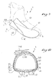
figure 4 est une vue schématique en perspective de la chaussure selon lafigure 1 , qui montre un renfort de la chaussure, - la
figure 5 est une coupe selon V-V de lafigure 1 , - la
figure 6 est une vue de côté de la chaussure de lafigure 1 , - la
figure 7 est une coupe dans l'esprit de lafigure 5 , pour une deuxième forme de réalisation de l'invention, - la
figure 8 est une coupe dans l'esprit de lafigure 5 , pour une troisième forme de réalisation de l'invention, - la
figure 9 est une vue schématique en perspective dans l'esprit de lafigure 4 , pour une quatrième forme de réalisation de l'invention, - la
figure 10 est une coupe dans l'esprit de lafigure 5 , pour la quatrième forme de réalisation de l'invention.
- the
figure 1 is a front perspective view of a shoe according to a first embodiment of the invention, which shows a lateral part, - the
figure 2 is a view, similar to thefigure 1 , which reveals a device for tightening the upper of the boot, - the
figure 3 is a perspective view before the shoe of thefigure 1 , which shows a medial part, - the
figure 4 is a schematic perspective view of the shoe according to thefigure 1 , which shows a reinforcement of the shoe, - the
figure 5 is a section according to VV of thefigure 1 , - the
figure 6 is a side view of the shoe of thefigure 1 , - the
figure 7 is a cut in the spirit of thefigure 5 for a second embodiment of the invention, - the
figure 8 is a cut in the spirit of thefigure 5 for a third embodiment of the invention, - the
figure 9 is a schematic perspective view in the spirit of thefigure 4 for a fourth embodiment of the invention, - the
figure 10 is a cut in the spirit of thefigure 5 for the fourth embodiment of the invention.
La première forme de réalisation qui va être décrite après concerne plus spécialement des chaussures pour la pratique du ski de fond, ou de télémark. Cependant l'invention s'applique à d'autres domaines tels que ceux évoqués avant.The first embodiment that will be described after more specifically relates to shoes for the practice of cross-country skiing, or telemark. However, the invention applies to other fields such as those mentioned before.
La première forme est décrite ci-après à l'aide des
Comme le montre la
De manière connue, la chaussure 1 comprend une semelle de marche 2 et une tige 3. La chaussure 1 s'étend en longueur depuis une extrémité arrière ou talon 4 jusqu'à une extrémité avant ou pointe 5, et en largeur entre une partie latérale 6 et une partie médiale 7.In known manner, the
Telle que représentée la tige 3 comprend une portion basse 10, prévue pour entourer le pied, ainsi qu'une portion haute 11, prévue pour entourer la cheville. Cependant, il pourrait être envisagé une tige comprenant seulement la portion basse.As shown the
Selon la première forme de réalisation décrite, la chaussure 1 s'étend en hauteur depuis la semelle 2 jusqu'à une extrémité supérieure 12, c'est-à-dire jusqu'à l'extrémité libre de la portion haute 11 ou de la tige 3.According to the first embodiment described, the
La chaussure 1 est structurée pour permettre une bonne flexion de la jambe ou un bon déroulement du pied, ainsi que la transmission d'informations sensorielles ou d'impulsions de conduite. C'est pourquoi la tige 3 est relativement souple. La semelle quant à elle peut être relativement rigide, ou bien plus souple.The
Comme on le voit mieux sur la
Bien entendu les quartiers 15, 16 sont solidarisés à la semelle par des techniques connues telles que le collage, la couture, ou tout équivalent. Les quartiers 15, 16 sont agencés de façon que la chaussure 1 présente une ouverture de chaussage 17. Celle-ci 17 s'étend depuis l'extrémité supérieure 12 vers l'extrémité avant 5. Du côté de l'extrémité supérieure 12 l'ouverture 17 présente une subdivision supérieure 18 destinée à laisser passer le pied, et aussi à entourer la cheville après chaussage. Au niveau du cou-de-pied, entre l'extrémité supérieure 12 et l'extrémité avant 5, l'ouverture 17 présente une subdivision inférieure 19 qui autorise une variation de dimension de l'ouverture et du volume de chaussage. Bien entendu, les subdivisions supérieure 18 et inférieure 19 se prolongent l'une l'autre.Of course the
On remarque que le talon 4 correspond bien sûr à l'extrémité arrière de la tige 3, mais aussi par extension à la partie de la tige située immédiatement au-dessus de la semelle, et à l'aplomb de la subdivision supérieure 18 de l'ouverture 17. Le talon 4 de la chaussure enveloppe le talon de l'utilisateur.Note that the
On observe que la tige 3 comprend une languette 20. Cette dernière 20 est disposée entre les quartiers latéral 15 et médial 16, au niveau de la subdivision inférieure 19 de l'ouverture 17, pour donner à la tige 3 sa continuité. Cependant il pourrait être prévu de ne pas utiliser de languette. Dans ce cas les quartiers 15, 16 peuvent rester séparés ou se superposer. Ou encore un soufflet peut relier l'un à l'autre les quartiers.It is observed that the
En complément, et de manière non obligatoire, la chaussure 1 comprend un rabat 25 prévu pour couvrir de manière réversible la subdivision inférieure 19 de l'ouverture 17. Le rabat 25 s'étend d'un quartier 15, 16 à l'autre, pour améliorer l'étanchéité de la chaussure.In addition, and not mandatory, the
Selon la première forme de réalisation, le rabat 25 est solidarisé de manière fixe au quartier médial 16. Une fermeture réversible 26 permet de solidariser le rabat 25 aussi au quartier latéral 15. Par exemple, la fermeture réversible 26 comprend une glissière. Cependant, toute autre structure pourrait être prévue pour réaliser la fermeture. Par exemple une suite de bouton-pression.According to the first embodiment, the
La chaussure 1 comprend encore un dispositif de serrage 30, prévu pour réduire l'ouverture de manière réversible. En d'autres termes le dispositif de serrage 30 permet de serrer la tige 3 de manière réversible.The
Comme il est connu de l'homme du métier, le dispositif de serrage 30 comprend par exemple un premier lien 31, un deuxième lien 32, ainsi que des liaisons 33 des liens à la tige 3. Bien entendu chaque lien chemine d'un quartier 15, 16 à l'autre au niveau de la subdivision inférieure 19. Cette structure permet d'exercer un serrage réversible de la tige 3 vers le cou-de-pied, au niveau de la subdivision inférieure 19 de l'ouverture 17. Ainsi il est possible d'exercer un serrage sur le pied de l'utilisateur. Pour maintenir provisoirement le serrage du dispositif 30, et donc de la tige 3, la chaussure 1 est munie d'un mécanisme de blocage amovible 34. Ce dernier n'est pas décrit en détail ici.As is known to those skilled in the art, the clamping
Il peut bien entendu être prévu tout autre moyen pour le maintien du serrage, notamment de supprimer le mécanisme de blocage et, à la place, réaliser un noeud.It can of course be provided any other means for maintaining the clamping, including removing the locking mechanism and, instead, make a node.
Comme il découle de l'ensemble des
Bien entendu le dessous 41 du renfort 40 supporte le pied, directement ou indirectement. Par corollaire les bords latéral 42 et médial 43 sont en vis-à-vis de zones latérale et médiale du pied. En conséquence, compte-tenu des rigidités relatives du renfort 40 et de la tige 3 dans la région du cou-de-pied, ainsi que de la localisation du lien transversal 50, un serrage de ce dernier maintient le pied appuyé directement, ou indirectement, sur le dessous 41 et sur l'un ou les deux bords 42, 43 du renfort. Cela assure une tenue précise du pied en direction verticale et en direction transversale, au moins au niveau du plan transversal.Of course, the bottom 41 of the
En référence notamment à la
Selon l'invention le dessous 41 s'étend depuis le talon 4 vers l'extrémité avant 5 de la chaussure, au-delà des extrémités avant latérale 47 et médiale 49 des bords latéral 42 et médial 43 du renfort 40. En d'autres termes les bords latéral 42 et médial 43 du renfort 40 s'étendent sur une longueur réduite de la chaussure. Plus précisément les bords latéral 42 et médial 43 s'étendent depuis le talon 4 jusqu'à l'aplomb du cou-de-pied, c'est-à-dire à hauteur du dispositif de serrage 30. Il s'ensuit que le talon et le cou-de-pied de l'utilisateur sont accueillis dans une forme creuse rigide, celle délimitée par le dessous 41 et la paroi 45, et que l'extrémité avant du pied est accueillie sur une portion plate du renfort 40, celle en avant des bords latéral 42 et médial 43. En fait cette portion plate permet une flexion de l'avant du pied, ou un déroulement, notamment au niveau des orteils.According to the invention the
On remarque que les bords latéral 42 et médial 43 sont sensiblement en regard l'un de l'autre ce qui, on le verra mieux après, facilite l'implantation du lien transversal 50 sur la chaussure.Note that the lateral edges 42 and medial 43 are substantially opposite one another which, as will be seen later, facilitates the implantation of the
Le renfort 40 est fabriqué à partir des matériaux et selon des procédés connus. De préférence le dessous 41 et les bords 42, 43, 44 forment une pièce monobloc. Celle-ci peut comprendre des fibres de matières synthétiques et/ou naturelles noyées dans une matrice. Par exemple des fibres de carbone et/ou de verre, imprégnées dans une résine thermodurcissable ou thermoformable, donnent au renfort 40 une grande rigidité. Il faut entendre par là une rigidité supérieure à celle du reste de la tige, notamment des quartiers 15, 16.The
Bien entendu il peut alternativement être prévu d'autres matériaux pour le renfort 40, par exemple une matière plastique chargée de particules et/ou de fibres coupées. Dans ce cas le renfort 40 est obtenu par moulage, par injection, ou tout procédé équivalent.Of course there may alternatively be provided other materials for the
Afin de coopérer avec le renfort 40, le lien transversal 50 est structuré et agencé pour être serré de manière réversible entre les bords latéral 42 et médial 43. Comme le montre notamment la
Le lien transversal 50 est solidarisé à au moins une partie du renfort 40.The
La première portion 51 s'étend longitudinalement entre une extrémité d'attache 54 et une extrémité libre 55. L'extrémité d'attache 54 est solidarisée à la partie latérale 6 par exemple à l'aide d'une articulation 56 d'axe 57. L'articulation 56 peut comprendre tout élément tel qu'une vis, un écrou, un rivet, ou autre.The
Plus précisément selon la première forme de réalisation, et de manière non limitative, la première portion 51 est solidarisée directement au renfort 40, en fait au bord latéral 42 du renfort.More specifically according to the first embodiment, and without limitation, the
La deuxième portion 52 quant à elle s'étend longitudinalement entre une extrémité d'attache 64 et une extrémité libre 65. L'extrémité d'attache 64 est solidarisée à la partie médiale 7 par un moyen comprenant un collage, une couture, une soudure, ou tout équivalent.The
Là encore de manière non limitative la deuxième portion 52 est solidarisée directement au renfort 40, en fait au bord médial 43 du renfort.Again, without limitation, the
Le premier moyen de liaison 53 est prévu pour relier de façon amovible la deuxième portion 52 à la première portion 51, l'extrémité libre 55 de la première portion 51 étant au-dessus de la deuxième portion 52. Ce moyen 53 comprend par exemple un mécanisme de serrage à cliquet 70 solidarisé à la deuxième portion 52, au niveau de l'extrémité libre 66 de cette dernière. Le moyen de liaison 53 comprend également une série de dents 71 conformées sur la première portion 51. Les dents 71 se répartissent depuis l'extrémité libre 55 jusqu'à proximité de l'articulation 56.The first connecting
La première portion 51 est réalisée par exemple sous la forme d'une crémaillère, faite à partir d'une matière plastique. Les dents 71 et l'âme 72 de la première portion 51 forment de préférence une pièce monobloc.The
Le mécanisme de serrage 70 comprend une embase 73 prévue pour guider la première portion 51. L'embase 73 comprend ici un premier flasque 74 et un deuxième flasque 75 reliés par un pont 76. L'embase 73 et solidarisée à la deuxième portion 52 par un moyen tel qu'un rivet, non représenté, ou tout équivalent.The
Le mécanisme de serrage 70 comprend un cliquet, non visible sur les figures, articulé selon un axe 77 entre les flasques 74, 75. Un moyen élastique non représenté, tel qu'un ressort, sollicite en permanence le cliquet vers le pont 76.The
Le mécanisme 70 comprend encore un levier d'entraînement 78, lequel comprend d'une part une extrémité de manutention 79 et, d'autre part, une extrémité d'entraînement 80 munie d'au moins une dent 81.The
Le mécanisme 70 comprend aussi un bouton de libération 85, lequel comprend une extrémité de manutention 86 prévue pour être actionnée à la main.The
Le levier d'entraînement 78 et le bouton de libération 85 sont articulés selon un même axe 87, entre les flasques 74, 75. Un moyen élastique non représenté, tel qu'un ressort, sollicite en permanence le levier 78 de façon que l'extrémité de manutention 79 soit poussée vers le pont 76. Ainsi en l'absence de toute sollicitation extérieure, les pièces constitutives du mécanisme de serrage 70 occupent chacune la position montrée à la
Lorsque la première portion 51 est présente le long du pont 76 entre les flasques 74, 75, dans l'embase 73, le cliquet s'oppose à un allongement du lien 50. A partir de là ce dernier 50 peut être raccourci, et donc la tige 3 peut être serrée, par action sur le levier 78. Il suffit de le faire tourner selon l'axe 87 de façon que les dents 81 entraînent la première portion 51. En conséquence le lien transversal 50 devient plus court, et le serrage de la chaussure au niveau du cou-de-pied est plus fort.When the
Bien entendu dans ce cas le pied logé dans la tige 3 est sollicité vers le renfort 40. En d'autres termes le pied est sollicité vers le dessous 41 et vers les bords latéral 42 et médial 43, au niveau du cou-de-pied. Il s'ensuit que le maintien du pied est meilleur, c'est-à-dire avec moins de jeux, aussi bien dans le sens de la hauteur que dans le sens transversal. Un avantage qui en découle est une plus grande précision de conduite.Of course in this case the foot housed in the
Comme on le comprend notamment à l'aide de la
Bien entendu à l'inverse l'utilisateur peut desserrer le lien, ou même l'ouvrir comme c'est le cas à la
D'une manière générale on observe que le renfort 40 et les quartiers latéral 15 et médial 16 appartiennent chacun aux parties latérale 6 et médiale 7 de la tige 3. Selon la première forme de réalisation de l'invention, et de manière non limitative, le renfort 40 est localisé à l'extérieur de la tige 3. Ainsi les quartiers 16, 16 longent la paroi 45 à l'intérieur du volume délimité par le renfort. Cela confère à la chaussure une esthétique plus agréable, et facilite aussi la fabrication. Cependant il peut alternativement être prévu que le renfort 40 soit disposé plus à l'intérieur de la tige. Dans ce cas les quartiers 15, 16 enveloppent en partie au moins le renfort 40.In general, it is observed that the
On observe aussi que la chaussure 1 comprend un moyen d'ancrage 89, pour une solidarisation réversible à un engin tel qu'un ski. Ce moyen 89 comprend par exemple une ou deux barres transversales, situées dans certains cas vers l'avant de la chaussure.It is also observed that the
Les autres formes de réalisations sont présentées ci-après à l'aide des
On retrouve donc pour la deuxième forme, selon la
Pour la deuxième forme de réalisation de l'invention la première portion 51 est solidarisée directement au renfort 40, plus précisément au bord latéral 42. Par contre, à la différence de la première forme, la deuxième portion 52 est solidarisée indirectement au renfort 40. En fait la deuxième portion 52 est solidarisée au quartier médial 16, par tout moyen tel qu'un collage, une soudure, une couture, un équivalent, ou une combinaison de ces moyens. On peut dire que la liaison de la deuxième portion 52 à la tige 3 est plus éloignée de la semelle 2 que ne l'est la liaison de la première portion 51. En d'autres termes la solidarisation du lien transversal 50 à la tige 3 est dissymétrique. Cela génère une légère différence dans l'application du serrage, entre la partie latérale 6 et la partie médiale 7. Le serrage est un peu plus marqué vers la partie latérale 6, compte-tenu de la souplesse des quartiers 15, 16 par rapport au renfort 40. Cela favorise la précision des appuis en direction latérale.For the second embodiment of the invention the
La troisième forme de réalisation de l'invention est présentée à l'aide de la
Ce qui est spécifique à la troisième forme de réalisation, ce sont la structure du lien transversal 100 et son implantation. Le lien transversal 100 comprend une première portion 101, une deuxième portion 102, et un moyen de liaison permanent 103 de la première portion 101 à la deuxième 102. En fait les portions 101, 102 sont liées l'une à l'autre de manière permanente par la liaison 103, représentée sous la forme d'une articulation. Celle-ci 103 peut comprendre un rivet, une vis, ou tout équivalent.What is specific to the third embodiment is the structure of the
La deuxième portion 102 est solidarisée de manière permanente, comme on l'a vu précédemment pour les portions 52, à la partie médiale 7. En complément un mécanisme de serrage à cliquet 110 est solidarisé de manière permanente à la partie latérale 6. Bien entendu le lien transversal 100 peut être serré, desserré, et ouvert. Dans ce cas la première portion 101 est séparée du mécanisme de serrage 110. Par rapport aux formes de réalisation précédentes, cette structure décale le mécanisme de serrage transversalement. Ici le décalage est orienté vers la partie latérale 6.The
La quatrième forme de réalisation est présentée à l'aide des
Un lien transversal 130 de la chaussure 1 comprend une portion unique 131 et un mécanisme de serrage 140. En fait le lien 130 contourne la tige 3 dans le plan transversal W à la manière d'une ceinture. Notamment la portion 131 traverse un conduit 141 ménagé au niveau de la semelle 2. Là encore le lien 130 peut être serré, desserré, ou ouvert. Même s'il n'y est pas solidarisé de manière permanente, le lien 130 relie l'une à l'autre les parties latérale 6 et médiale 7. Ici la structure du lien 130 est simplifiée.A
Dans tous les cas l'invention est réalisée à partir de matériaux et selon des techniques de mise en oeuvre connus de l'homme du métier.In all cases the invention is made from materials and according to processing techniques known to those skilled in the art.
Bien entendu l'invention n'est pas limitée aux formes de réalisation ci-avant décrites, elle est définie par la portée des revendications qui vont suivre.Naturally, the invention is not limited to the embodiments described above, it is defined by the scope of the claims that follow.
En particulier dans tous les cas l'architecture d'un lien transversal peut être inversée, dans le sens où les spécificités liées à une partie latérale peuvent se retrouver sur une partie médiale et vice versa.In particular, in all cases the architecture of a transversal link can be reversed, in the sense that the specificities related to a lateral part can be found on a medial part and vice versa.
Claims (13)
- Boot (1) comprising a sole (2) and an upper (3), the boot (1) extending lengthwise from a heel (4) to a front end (5), widthwise between a lateral part (6) and a medial part (7), and heightwise from the sole (2) to an upper end (12), the boot (1) having an opening (17) allowing the foot to enter, and comprising a tightening device (30) provided to reversibly reduce the opening, the boot (1) comprising a transverse connection (50, 100, 130) provided for gripping the ankle region, the connection (50, 100, 130) extending from the lateral part (6) to the medial part (7) in a transverse plane (W) of the boot,
the boot comprising a reinforcement (40) which is stiffer than the upper (3) at least in the region of the ankle, the reinforcement (40) extending vertically from the ankle, the reinforcement (40) being part of the upper (3), the reinforcement (40) comprising an underside (41), a lateral edge (42) and a medial edge (43), the lateral edge (42) and/or the medial edge (43) extending over a reduced length of the boot, the underside (41) extending from the heel (4) towards the front end (5) of the boot, beyond the lateral (47) and medial (49) front ends of the lateral edge (42) and of the medial edge (43) of the reinforcement (40). - Boot (1) according to Claim 1, characterized in that the reinforcement (40) also comprises a rear edge (44).
- Boot (1) according to either of Claims 1 and 2, characterized in that the reinforcement (40) is located outside the upper (3).
- Boot (1) according to one of Claims 1 to 3, characterized in that the transverse connection (50, 100, 130) is secured to at least one part of the reinforcement (40).
- Boot (1) according to one of Claims 1 to 4, characterized in that the transverse connection (50) comprises a first portion (51), a second portion (52), and a connection means (53) provided for removably connecting the second portion (52) to the first portion (51).
- Boot (1) according to Claim 5, characterized in that the first portion (51) is secured directly to the reinforcement (40), and in that the second portion (52) is secured directly to the reinforcement (40).
- Boot (1) according to Claim 5, characterized in that the first portion (51) is secured directly to the reinforcement (40), and in that the second portion (52) is secured indirectly to the reinforcement (40).
- Boot (1) according to one of Claims 1 to 4, characterized in that the transverse connection (100) comprises a first portion (101), a second portion (102), and a means (103) for permanently connecting the first portion (101) to the second (102), and in that a tightening mechanism (110) is permanently secured to the lateral part (6).
- Boot (1) according to one of Claims 1 to 3, characterized in that the transverse connection (130) wraps around the upper (3) in the transverse plane (W) in the manner of a belt.
- Boot (1) according to one of Claims 1 to 9, characterized in that the transverse plane (W) forms, with a plane (P) which is tangential to the sole (2), an angle (α) of between 50 and 90 degrees.
- Boot (1) according to one of Claims 1 to 9, characterized in that the transverse plane (W) intersects a plane (P), which is tangential to the sole (2), vertically in line with a tightening device (30).
- Boot (1) according to one of Claims 1 to 9, characterized in that the transverse plane (W) intersects a plane (P), which is tangential to the sole (2), vertically approximately in line with the intersection (88) of the upper (18) and lower (19) subdivisions of an opening (17) for inserting the foot.
- Boot (1) according to one of Claims 1 to 9, characterized in that the transverse connection (50, 100, 130) is connected to the upper (3) in front of the heel (4).
Applications Claiming Priority (1)
| Application Number | Priority Date | Filing Date | Title |
|---|---|---|---|
| FR0707951A FR2923362B1 (en) | 2007-11-13 | 2007-11-13 | IMPROVED ROD TIGHTENING SHOE |
Publications (2)
| Publication Number | Publication Date |
|---|---|
| EP2060196A1 EP2060196A1 (en) | 2009-05-20 |
| EP2060196B1 true EP2060196B1 (en) | 2015-10-07 |
Family
ID=39485206
Family Applications (1)
| Application Number | Title | Priority Date | Filing Date |
|---|---|---|---|
| EP08018316.3A Not-in-force EP2060196B1 (en) | 2007-11-13 | 2008-10-20 | Boot with improved leg tightening |
Country Status (6)
| Country | Link |
|---|---|
| US (1) | US20090119952A1 (en) |
| EP (1) | EP2060196B1 (en) |
| CN (1) | CN101433388B (en) |
| DE (1) | DE202008017700U1 (en) |
| FR (1) | FR2923362B1 (en) |
| RU (1) | RU2497423C2 (en) |
Families Citing this family (20)
| Publication number | Priority date | Publication date | Assignee | Title |
|---|---|---|---|---|
| RU2414275C1 (en) * | 2010-03-16 | 2011-03-20 | Николай Иванович Максимов | Transport vehicle (versions): ski, ski rollers, ski hinging, ski boots and methods of transport vehicle run |
| FR2965458B1 (en) * | 2010-09-30 | 2013-08-16 | Salomon Sas | REINFORCED SHOE |
| FR2971675B1 (en) * | 2011-02-21 | 2014-10-10 | Eurl Gignoux | FLEXIBLE SHOE SHELL AT THE METATARSO-PHALANGIAN JOINT |
| FR2980959A1 (en) | 2011-10-10 | 2013-04-12 | Salomon Sas | IMPROVED ROD TIGHTENING SHOE |
| FR2981250B1 (en) * | 2011-10-12 | 2013-11-22 | Salomon Sas | IMPROVED SHOE SHOES |
| US20130298426A1 (en) * | 2012-05-14 | 2013-11-14 | Elisha George Pierce | Tongueless Footwear With A Canopy |
| US10206451B2 (en) | 2012-07-06 | 2019-02-19 | Specialized Bicycle Components, Inc. | Cycling shoe |
| US20140150300A1 (en) * | 2012-11-30 | 2014-06-05 | Salomon S.A.S. | Adaptable sports footwear |
| FR2999059B1 (en) * | 2012-12-07 | 2015-01-30 | Salomon Sas | FORMING DEVICE APPLIED TO A SHOE |
| ITTV20130159A1 (en) * | 2013-10-09 | 2015-04-10 | Scarpa Calzaturificio Spa | MOUNTAIN BOOT |
| CN105326150B (en) * | 2015-11-23 | 2017-01-25 | 陕西科技大学 | Elderly adjustable hallux valgus pain relief curved last shoes |
| USD943945S1 (en) | 2020-07-31 | 2022-02-22 | Specialized Bicycle Components, Inc. | Bicycle shoe |
| USD975969S1 (en) | 2020-10-27 | 2023-01-24 | Specialized Bicycle Components, Inc. | Shoe |
| USD975970S1 (en) | 2020-12-23 | 2023-01-24 | Specialized Bicycle Components, Inc. | Shoe |
| USD974005S1 (en) | 2020-12-23 | 2023-01-03 | Specialized Bicycle Components, Inc. | Shoe |
| USD975405S1 (en) | 2021-01-14 | 2023-01-17 | Specialized Bicycle Components, Inc. | Shoe |
| USD1030260S1 (en) | 2021-09-27 | 2024-06-11 | Specialized Bicycle Components, Inc. | Shoe |
| USD1050685S1 (en) | 2021-10-15 | 2024-11-12 | Specialized Bicycle Components, Inc. | Shoe |
| USD1052853S1 (en) | 2021-12-06 | 2024-12-03 | Specialized Bicycle Components, Inc. | Shoe |
| CN114916744B (en) * | 2022-06-01 | 2023-07-21 | 广东悍戈防护科技有限公司 | Military and police warm combat boots |
Family Cites Families (29)
| Publication number | Priority date | Publication date | Assignee | Title |
|---|---|---|---|---|
| US3408754A (en) * | 1967-07-03 | 1968-11-05 | Hubert C. Kueter | Ski boot stiffening |
| US3561139A (en) * | 1969-08-25 | 1971-02-09 | Donald W Stillman | Ski boot and stay therefor |
| US3849914A (en) * | 1972-09-01 | 1974-11-26 | F B S A S Dia Bertele Giovanni | Ski boot |
| DE7729564U1 (en) | 1977-09-23 | 1978-01-05 | Puma-Sportschuhfabriken Rudolf Dassler Kg, 8522 Herzogenaurach | Sports shoe with laces and straps |
| US4677769A (en) * | 1986-02-28 | 1987-07-07 | Eddress Ahmad | Footwear with pivotal toe |
| AT387893B (en) * | 1986-10-10 | 1989-03-28 | Tyrolia Freizeitgeraete | Cross-country ski boot |
| US4920665A (en) * | 1987-04-13 | 1990-05-01 | Pack Roger N | Pivoting ski boot |
| US5317820A (en) * | 1992-08-21 | 1994-06-07 | Oansh Designs, Ltd. | Multi-application ankle support footwear |
| FR2702935B1 (en) * | 1993-03-24 | 1995-06-09 | Salomon Sa | SLIDING SPORTS SHOE. |
| US5906058A (en) * | 1993-07-19 | 1999-05-25 | K-2 Corporation | Snowboard boot having a rigid strut |
| IT1279471B1 (en) * | 1995-11-16 | 1997-12-10 | Tecnica Spa | NON-RIGID SHOE FOR SNOW BOARD |
| FR2743988B1 (en) * | 1996-01-30 | 1998-03-20 | Salomon Sa | SPORTS SHOE |
| US6543159B1 (en) * | 1996-03-21 | 2003-04-08 | The Burton Corporation | Snowboard boot and binding strap |
| FR2759552B1 (en) * | 1997-02-19 | 1999-04-23 | Salomon Sa | SPORT SHOE WITH RIGID FRAME |
| FR2765083B1 (en) * | 1997-06-27 | 1999-08-27 | Salomon Sa | MULTILAYERED SOLE COUPLED TO SHOE UPPER REINFORCEMENT |
| FR2787682B1 (en) * | 1998-12-23 | 2001-01-26 | Salomon Sa | SPORTS SHOE |
| US6226898B1 (en) * | 1999-05-28 | 2001-05-08 | K-2 Corporation | Downhill ski boot with dual liner |
| EP1292369B1 (en) * | 2000-06-08 | 2005-12-07 | Rottefella AS | System consisting of ski binding and ski boot |
| FR2818505B1 (en) * | 2000-12-22 | 2004-06-18 | Salomon Sa | SHOE |
| ATE357858T1 (en) * | 2001-01-22 | 2007-04-15 | Scarpa Calzaturificio Spa | SKI BOOTS |
| ITTV20010050A1 (en) * | 2001-04-23 | 2002-10-23 | Tecnica Spa | ARTICULATED REINFORCEMENT STRUCTURE AND FOOTWEAR EQUIPPED WITH SUCH STRUCTURE |
| US6588125B2 (en) * | 2001-05-22 | 2003-07-08 | Charles Wesley Proctor, Sr. | Articulated ski boot |
| DE60131107T2 (en) * | 2001-05-23 | 2008-10-02 | Heierling I-Flex Gmbh | BOOT |
| US6592920B2 (en) * | 2001-06-21 | 2003-07-15 | Kraft Foods Holdings, Inc. | Cereal ingredient application process |
| FR2832036B1 (en) * | 2001-11-13 | 2004-04-02 | Salomon Sa | SPORTS SHOE WITH UPPER ON THE UPPER |
| FR2855946B1 (en) * | 2003-06-12 | 2006-02-10 | Salomon Sa | SHOE |
| FR2856312B1 (en) * | 2003-06-18 | 2005-08-05 | Salomon Sa | SWIVEL ARM FIXING DEVICE |
| ITTO20030753A1 (en) * | 2003-09-26 | 2005-03-27 | Marco Rigat | MULTI-FUNCTION TELEMARK BOOT |
| FR2884394B1 (en) * | 2005-04-13 | 2007-05-25 | Salomon Sa | SPORT SHOE WITH EASY ENTRANCE |
-
2007
- 2007-11-13 FR FR0707951A patent/FR2923362B1/en not_active Expired - Fee Related
-
2008
- 2008-10-20 DE DE202008017700U patent/DE202008017700U1/en not_active Expired - Lifetime
- 2008-10-20 EP EP08018316.3A patent/EP2060196B1/en not_active Not-in-force
- 2008-11-12 CN CN2008101754180A patent/CN101433388B/en not_active Expired - Fee Related
- 2008-11-12 RU RU2008144760/12A patent/RU2497423C2/en not_active IP Right Cessation
- 2008-11-12 US US12/269,364 patent/US20090119952A1/en not_active Abandoned
Also Published As
| Publication number | Publication date |
|---|---|
| FR2923362A1 (en) | 2009-05-15 |
| CN101433388B (en) | 2012-02-22 |
| US20090119952A1 (en) | 2009-05-14 |
| DE202008017700U1 (en) | 2010-03-25 |
| FR2923362B1 (en) | 2010-04-30 |
| RU2008144760A (en) | 2010-05-20 |
| CN101433388A (en) | 2009-05-20 |
| EP2060196A1 (en) | 2009-05-20 |
| RU2497423C2 (en) | 2013-11-10 |
Similar Documents
| Publication | Publication Date | Title |
|---|---|---|
| EP2060196B1 (en) | Boot with improved leg tightening | |
| EP2314177B1 (en) | Boot with improved leg tightening | |
| EP2052636B1 (en) | Boot with improved leg tightening | |
| EP1769692B1 (en) | Shoe which enhances the retaining of the heel | |
| EP2198729B1 (en) | Shoe with improved bottom assembly | |
| EP2580978A1 (en) | Schuh mit verbesserter Einspannmöglichkeit des Schafts | |
| FR2844683A1 (en) | Boot, in particular for being used with skis, roller-skates, or snowboard, comprising tensioning arrangement for reduced unintentional motion of foot | |
| EP2580980B1 (en) | Schuh mit verbessertem Schaft | |
| EP1688055A1 (en) | Sports shoe | |
| WO2012114002A2 (en) | Shoe for practicing sports involving gliding over the snow, or for walking | |
| CA2729398A1 (en) | Footwear with improved upper | |
| EP3847919A1 (en) | Fastening device for shoes | |
| FR2953692A1 (en) | IMPROVED SHOE SHOES | |
| EP1935460A1 (en) | Article comprising a link for holding or tightening a foot or a shoe | |
| FR2534116A1 (en) | Flat sports shoe for langlauf skiing | |
| EP2374513A1 (en) | Device for accommodating a foot or footwear on a snow gliding device | |
| EP1327467A1 (en) | Device for retaining a shoe to a sporting article | |
| WO1993025107A1 (en) | Shoe with foot retaining device | |
| EP1900399A1 (en) | Article comprising a link including a magnet for holding or tightening a foot or a shoe | |
| FR2848869A1 (en) | Snowboard boot retaining device comprises lateral and medial parts delimiting boot reception zone with link connected to each part, portion of link lateral and medial portions able to be separated from reception zone | |
| EP2481315B1 (en) | Fitting element provided with an improved tightening device | |
| FR2871069A1 (en) | DEVICE FOR MAINTAINING A FOOT OR SHOE | |
| FR2656775A1 (en) | SKI SHOE IN PLASTIC MATERIAL. | |
| FR2878757A1 (en) | Shoe or foot maintenance device for practicing e.g. snow boarding, has apron connected to lateral or medial flanges by lateral or medial attachment independent of connections, and articulation maintaining rear support unit and rear division | |
| EP2481314B1 (en) | Footwear in which the upper includes a top portion |
Legal Events
| Date | Code | Title | Description |
|---|---|---|---|
| PUAI | Public reference made under article 153(3) epc to a published international application that has entered the european phase |
Free format text: ORIGINAL CODE: 0009012 |
|
| AK | Designated contracting states |
Kind code of ref document: A1 Designated state(s): AT BE BG CH CY CZ DE DK EE ES FI FR GB GR HR HU IE IS IT LI LT LU LV MC MT NL NO PL PT RO SE SI SK TR |
|
| AX | Request for extension of the european patent |
Extension state: AL BA MK RS |
|
| 17P | Request for examination filed |
Effective date: 20091016 |
|
| 17Q | First examination report despatched |
Effective date: 20091127 |
|
| AKX | Designation fees paid |
Designated state(s): AT CH DE FI FR LI NO |
|
| GRAP | Despatch of communication of intention to grant a patent |
Free format text: ORIGINAL CODE: EPIDOSNIGR1 |
|
| RIC1 | Information provided on ipc code assigned before grant |
Ipc: A43B 5/16 20060101ALI20150513BHEP Ipc: A43B 5/04 20060101AFI20150513BHEP Ipc: A43B 23/16 20060101ALI20150513BHEP Ipc: A43C 11/14 20060101ALI20150513BHEP |
|
| INTG | Intention to grant announced |
Effective date: 20150603 |
|
| GRAS | Grant fee paid |
Free format text: ORIGINAL CODE: EPIDOSNIGR3 |
|
| GRAA | (expected) grant |
Free format text: ORIGINAL CODE: 0009210 |
|
| AK | Designated contracting states |
Kind code of ref document: B1 Designated state(s): AT CH DE FI FR LI NO |
|
| REG | Reference to a national code |
Ref country code: AT Ref legal event code: REF Ref document number: 753154 Country of ref document: AT Kind code of ref document: T Effective date: 20151015 Ref country code: CH Ref legal event code: EP |
|
| REG | Reference to a national code |
Ref country code: DE Ref legal event code: R096 Ref document number: 602008040484 Country of ref document: DE |
|
| REG | Reference to a national code |
Ref country code: AT Ref legal event code: MK05 Ref document number: 753154 Country of ref document: AT Kind code of ref document: T Effective date: 20151007 |
|
| PG25 | Lapsed in a contracting state [announced via postgrant information from national office to epo] |
Ref country code: NO Free format text: LAPSE BECAUSE OF FAILURE TO SUBMIT A TRANSLATION OF THE DESCRIPTION OR TO PAY THE FEE WITHIN THE PRESCRIBED TIME-LIMIT Effective date: 20160107 |
|
| REG | Reference to a national code |
Ref country code: DE Ref legal event code: R119 Ref document number: 602008040484 Country of ref document: DE |
|
| PG25 | Lapsed in a contracting state [announced via postgrant information from national office to epo] |
Ref country code: AT Free format text: LAPSE BECAUSE OF FAILURE TO SUBMIT A TRANSLATION OF THE DESCRIPTION OR TO PAY THE FEE WITHIN THE PRESCRIBED TIME-LIMIT Effective date: 20151007 Ref country code: FI Free format text: LAPSE BECAUSE OF FAILURE TO SUBMIT A TRANSLATION OF THE DESCRIPTION OR TO PAY THE FEE WITHIN THE PRESCRIBED TIME-LIMIT Effective date: 20151007 |
|
| REG | Reference to a national code |
Ref country code: CH Ref legal event code: PL |
|
| PG25 | Lapsed in a contracting state [announced via postgrant information from national office to epo] |
Ref country code: DE Free format text: LAPSE BECAUSE OF NON-PAYMENT OF DUE FEES Effective date: 20160503 Ref country code: CH Free format text: LAPSE BECAUSE OF NON-PAYMENT OF DUE FEES Effective date: 20151031 Ref country code: LI Free format text: LAPSE BECAUSE OF NON-PAYMENT OF DUE FEES Effective date: 20151031 |
|
| PLBE | No opposition filed within time limit |
Free format text: ORIGINAL CODE: 0009261 |
|
| STAA | Information on the status of an ep patent application or granted ep patent |
Free format text: STATUS: NO OPPOSITION FILED WITHIN TIME LIMIT |
|
| REG | Reference to a national code |
Ref country code: FR Ref legal event code: ST Effective date: 20160809 |
|
| 26N | No opposition filed |
Effective date: 20160708 |
|
| PG25 | Lapsed in a contracting state [announced via postgrant information from national office to epo] |
Ref country code: FR Free format text: LAPSE BECAUSE OF NON-PAYMENT OF DUE FEES Effective date: 20151207 |