EP2042963A2 - Method and system for automatic path planning and obstacle/collision avoidance of autonomous vehicles - Google Patents
Method and system for automatic path planning and obstacle/collision avoidance of autonomous vehicles Download PDFInfo
- Publication number
- EP2042963A2 EP2042963A2 EP08159084A EP08159084A EP2042963A2 EP 2042963 A2 EP2042963 A2 EP 2042963A2 EP 08159084 A EP08159084 A EP 08159084A EP 08159084 A EP08159084 A EP 08159084A EP 2042963 A2 EP2042963 A2 EP 2042963A2
- Authority
- EP
- European Patent Office
- Prior art keywords
- vehicle
- path
- domain
- goal
- intersection
- Prior art date
- Legal status (The legal status is an assumption and is not a legal conclusion. Google has not performed a legal analysis and makes no representation as to the accuracy of the status listed.)
- Withdrawn
Links
- 238000000034 method Methods 0.000 title claims abstract description 38
- 238000005259 measurement Methods 0.000 claims description 2
- 238000010586 diagram Methods 0.000 description 5
- 238000012545 processing Methods 0.000 description 5
- 239000003973 paint Substances 0.000 description 4
- 230000001788 irregular Effects 0.000 description 3
- XLYOFNOQVPJJNP-UHFFFAOYSA-N water Substances O XLYOFNOQVPJJNP-UHFFFAOYSA-N 0.000 description 3
- 238000013459 approach Methods 0.000 description 2
- 238000004891 communication Methods 0.000 description 2
- 230000006870 function Effects 0.000 description 2
- 238000000926 separation method Methods 0.000 description 2
- 108050005509 3D domains Proteins 0.000 description 1
- RZVHIXYEVGDQDX-UHFFFAOYSA-N 9,10-anthraquinone Chemical compound C1=CC=C2C(=O)C3=CC=CC=C3C(=O)C2=C1 RZVHIXYEVGDQDX-UHFFFAOYSA-N 0.000 description 1
- 241000408659 Darpa Species 0.000 description 1
- 230000006978 adaptation Effects 0.000 description 1
- 238000004590 computer program Methods 0.000 description 1
- 239000004020 conductor Substances 0.000 description 1
- 238000013500 data storage Methods 0.000 description 1
- 238000012804 iterative process Methods 0.000 description 1
- 230000007774 longterm Effects 0.000 description 1
- 239000004065 semiconductor Substances 0.000 description 1
- 238000012360 testing method Methods 0.000 description 1
- 239000002699 waste material Substances 0.000 description 1
Images


Classifications
-
- G—PHYSICS
- G05—CONTROLLING; REGULATING
- G05D—SYSTEMS FOR CONTROLLING OR REGULATING NON-ELECTRIC VARIABLES
- G05D1/00—Control of position, course, altitude or attitude of land, water, air or space vehicles, e.g. using automatic pilots
- G05D1/10—Simultaneous control of position or course in three dimensions
- G05D1/101—Simultaneous control of position or course in three dimensions specially adapted for aircraft
- G05D1/106—Change initiated in response to external conditions, e.g. avoidance of elevated terrain or of no-fly zones
Definitions
- Embodiments of the present invention provide a system for automatic path planning and collision avoidance for autonomous vehicles.
- Such vehicles include air, land and water vehicles.
- Embodiments implement obstacle avoidance algorithms in software and run the software onboard the vehicles' computers.
- the software is run by a control station that is associated with many small unmanned vehicles.
- an obstacle free path is uploaded (in real time) to the vehicle's computer over a communication link.
- Embodiments use a laplacian algorithm for path planning, obstacle avoidance and collision avoidance.
- a multi-sized grid technique is applied to plan a path and for collision avoidance.
- the vehicle system 100 includes an input-path generating module 102 that includes an operator input 104 that sets waypoints and a path generation 106 that plans a path based on the waypoints.
- the system further includes a guidance module 108.
- the operator input 104 of the input-path generating module 102 provides manual velocity commands to the guidance module 108.
- the operator input 104 includes a receiver to receive remote communications from a central command.
- the path generation 106 of the input-path generating module 102 provides a planned path to the guidance module 108.
- the guidance module 108 includes guidance system 110, collision avoidance system 112 and switch 114.
- guidance commands are output from the guidance module 108 to a vehicle control module 124.
- the vehicle control module is a flight control 124.
- the vehicle control module 124 can be a control for any type of vehicle such as ground based vehicle including trucks or cars and even water vessels.
- the vehicle control module 124 provides control signals to a vehicle 126.
- the example of control signals in Figure 1 includes throttle control signals and vane control signals. It will be understood that other type of control signals depending of the vehicle being controlled.
- the vehicle system 100 includes a sensor system 118 that provides a feedback loop to the guidance module 108.
- the sensor system 118 in this example includes sensors 122 such as an inertial measurement unit (IMU), global positioning system (GPS) and Barometric pressure sensors and a collision avoidance sensor 120.
- sensors 122 such as an inertial measurement unit (IMU), global positioning system (GPS) and Barometric pressure sensors and a collision avoidance sensor 120.
- An example of collision avoidance sensor is a scanning laser range-finder system (LADAR).
- LADAR scanning laser range-finder system
- the sensors 122 provide a measured vehicle state to navigation algorithms 116.
- the navigation algorithms 116 provide a feedback signal of vehicle state estimates to the guidance module 108.
- the collision avoidance sensor 120 provides a measured obstacle relative position signal to the guidance module 108.
- the vehicle type i.e.
- the guidance module 108 in some embodiments implements specific logic dictated by the then current situation in generating the control signals. For example, in regards to a land vehicle in an urban setting, traffic logic is implemented. An example of this type of logic is discussed below in relation to Figures 7-9 of the specification.
- FIG. 2A A block diagram of an obstacle avoidance system 200 incorporating a laplacian algorithm of one embodiment is illustrated in Figure 2A .
- the avoidance system 200 in this example uses two different algorithms for collision avoidance.
- the first algorithm is a long range algorithm 208 which is best used as generally a long-range planner for dense obstacles.
- the second is a short term algorithm 216 which is faster and better suited for sparse obstacles.
- the avoidance system 200 integrates both the long range algorithm 208 and the short term algorithm 216.
- the long range algorithm 208 is a laplacian 208.
- a second laplacian is used for the short range algorithm.
- a single laplacian is used for both the long range and the short range algorithms.
- waypoints 202 are provide to the laplacian 208 and to a waypoint selection logic 214.
- Ladar sensor 204 provides signals relating to obstacles to an evidence grid 206 which uses inertial coordinates and provides signals to the laplacian 208, a speed controller 212, the waypoint selection logic 214 and the short range algorithm 216.
- the laplacian 208 provides an output signal to a compute path from gradient of potential module 210 which outputs a signal to the speed controller 212 and the waypoint selection logic 214.
- the speed controller 212 provide a speed signal to a velocity command module 218 that controls speed and direction.
- the short range algorithm 216 outputs a direction signal to the velocity command 218.
- the velocity command 218 outputs a control signal to vehicle control module 220.
- the laplacian algorithm is run at a slower frequency (1/2 Hz) than the short range algorithm (5 Hz).
- Other types of avoidance systems are contemplated including systems that only incorporate a laplacian and the present invention is not limited to an integrated system.
- FIG. 2B An example of a collision avoidance system 230 that only incorporates a laplacian is illustrated in Figure 2B .
- This system 230 is geared towards a ground vehicle.
- the system 230 includes a waypoint processing module 232 that receives inputs 250. Examples of the inputs include information related to but not limited to waypoints sequence, waypoint reached, vehicle full state, map, is safety area flag, speed limit of current segment, max-min allowable turn radii, undulation factor of path ahead, vehicle separation and map coordinate frame.
- the waypoint processing module 232 communicates waypoint and convergence flag information with the laplacian algorithm 234.
- the waypoint processing module 232 further provides vehicle separation information to a speed planner 238.
- the laplacian 234 provides a potential to a compute gradient module 236.
- the compute gradient 236 provides a projected path to the speed planer 238.
- the inputs are also provided to a map processing module 240.
- the map processing module 240 provides an output to the laplacian 234 and the speed planner 238.
- the speed planner 238 receives stop at intersection/N-pt turn path points information from an intersection logic and N-point turn module 242.
- the speed planner 238 in turn provides an output to a compute-shortest-path-time module 244 and an output 252. Examples of the output include but are not limited to most recent waypoint reached, notify unreachable waypoint, direction (forward, back), speed, turn signal and shortest waypoint time.
- the methods and techniques used by the autonomous vehicle system 100 and the collision avoidance systems 200 and 230 as described above can be implemented in digital electronic circuitry, or with a programmable processor (for example, a special-purpose processor or a general-purpose processor such as a computer) firmware, software, or in combinations of them.
- Apparatus embodying these techniques may include appropriate input and output devices, a programmable processor, and a storage medium tangibly embodying program instructions for execution by the programmable processor.
- a process embodying these techniques may be performed by a programmable processor executing a program of instructions to perform desired functions by operating on input data and generating appropriate output.
- the techniques may advantageously be implemented in one or more programs that are executable on a programmable system including at least one programmable processor coupled to receive data and instructions from, and to transmit data and instructions to, a data storage system, at least one input device, and at least one output device.
- a processor will receive instructions and data from a read-only memory and/or a random access memory.
- Storage devices suitable for tangibly embodying computer program instructions and data include all forms of non-volatile memory, including by way of example semiconductor memory devices, such as EPROM, EEPROM, and flash memory devices; magnetic disks such as internal hard disks and removable disks; magnetooptical disks; and DVD disks. Any of the foregoing may be supplemented by, or incorporated in, specially-designed application-specific integrated circuits (ASICs).
- ASICs application-specific integrated circuits
- FIG. 3 in illustration of a path planning and obstacle avoidance graph 300 using laplacian methods is provided.
- the graph illustrates obstacles 306 (buildings) and a path 302 defined by waypoints 304.
- two uncharted obstacles 308 and 310 are encountered.
- Vehicle 312 must avoid the uncharted obstacles 308 and 310 as it traverses around the buildings 306.
- the sensor signals 314 used to sense the uncharted obstacles 308 and 310 and are used to sense visible points 320 on all obstacles.
- the sensed obstacle points are stored in a database.
- a path from any initial point, r(0), to the goal, is constructed by following the negative gradient of the potential, v.
- Laplace's equation sets the divergence of a potential to zero in the interior of a domain. Solutions of Laplace's equation are harmonic functions, which have no local minima in the interior of their domain.
- Numerical solutions of Laplace's equation in embodiments are obtained by gridding the domain, then iteratively setting the potential at each interior point, equal to the average of its nearest neighbors.
- a laplacian path-planning obstacle-avoidance is applied by gridding up a domain with points r(i,j) in 2D (similar for 3D)
- Figures 10 A-D.
- Embodiments use a grid system to plan a path.
- An example of a grid system 406 is illustrated in traverse graph 400 of Figure 4A .
- the grid size is selected to provide sufficient grids 406 between obstacles 402 and 404.
- a 10 grid count 410 is between building 402 and the next closest obstacle 404 is used.
- Figure 4A further illustrates a vehicle path 408 and a waypoint 412.
- a (64 wide) X (64 deep) and a 32 (high) evidence grid is used in the traverse graph 400 .
- Another example of a traverse grid 410 is illustrated in Figure 4B .
- waypoint 430 on a grid 422 is illustrated.
- Figure 4B further illustrates, the path to a waypoint 430 traverses around buildings 424.
- either a 128 X 128 X 64 evidence grid is used with a (3ft) 3 cubes or a 64 X 64 X 32 grid with (6ft) 3 cubes are used depending on the level of accuracy needed.
- the size of the cells that make up the grid in a graph is varied.
- the grid size halving or doubling cell length at each step
- the iteration can be made to converge in a time proportional to the number, N, of cells in the finest grid.
- the solution on crude grids is cheap, and is used to initialize the solution on finer grids. This multi-sized grid technique is applied to robotic path planning.
- Textbook convergence proofs for empty domains give the total number of computations to be c*N, where N is the number of cells in the finest grid, and c ⁇ 5 is some small number of iterations at each grid size. That convergence speed relies on being able to set the crudest grid cell size equal to the entire domain for the crudest solution. However, in a domain with obstacles, the number of needed iterations is given by c*(path length)/(path width), since path-width between obstacles, limits the largest cell size of the crudest grid that still preserves the topology of the computed paths. With largest grid cell size set equal to path width, the number of grid cells along the path equals (path length)/(path width).
- the iterative process of setting a cell's potential equal to the average of its neighbor's potentials propagates a nonzero solution value a distance of one more grid cell along the path, each iteration. So it takes (path length)/(path width) iterations for a nonzero solution to propagate along the entire path length, when crudest grid cell size is equal to path width. After c*(path length)/(path width) iterations, with c ⁇ 5, the iteration converges on the crudest grid.
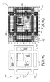
- FIG. 4C an example of an area 440 to be traversed in illustrated.
- the area to be traversed includes roads 441, parking lots 446, buildings 444 and open spaces 442.
- a Lidar scans the road and records road edges and lane markers. Edge pixels are stored in a quadtree using a nearest-neighbor algorithm.
- the quadtree is an irregular quadtree since the size of the grids vary.
- Application of the irregular quadtree is illustrated in Figure 4D . As illustrated, the finest pixels (smallest grid points) are at obstacle edges.
- FIG. 5 An example, of a grid system 500 in 3 dimensions is illustrated in Figure 5 .
- an air vehicle is to traverse through the grid system 500 starting at point 502 through waypoints 504, 506, 508, 510 to ending point 512.
- an obstacle 514 is encountered between waypoint 510 and end point 512.
- the obstacle 514 in this example is a power line 514.
- an alternate path 516 is determined and followed.
- the system is deactivated so that it does not waste energy trying to correct tiny errors that are too small to matter.
- a fixed-size computation box system 600 is moved over a much larger map, to limit the amount of computing needed, as illustrated in Figure 6 .
- Computations are only done on the part of the map that is inside the computation box. However, in some cases the goal point is far away, so the goal point may be outside the computation box. If there were nothing inside the computation box that represented the goal, then no path towards the goal could be computed inside the computation box. So the goal is temporarily represented by an artificial goal at the edge of the computation box.
- the computation box system 600 keeps a box centered on a moving vehicle. In this embodiment, if the goal is inside the computation box, then a path to the goal is determined. If the goal is outside the computational box, a straight line is drawn from the vehicle to the goal.
- intersection illustration 700 is illustrated.
- FIG. 7 illustrates intersections 702 and 704 with stop signs.
- a vehicle arrives at a stop sign, it observes which other stop signs have queued traffic at them. The vehicle then waits until one vehicle leaves each of these queues and the intersection clears. Once the intersection has cleared, the vehicle then passes through the intersection. If another vehicle has not left its queue for 10 seconds after it could have, it is timed out and the current vehicle will proceed without waiting for the other vehicle.
- FIG. 8 a vehicle control over a traverse area 800 of one embodiment is illustrated.
- the traverse area 800 is defined by curbs 802 and centerlines 804.
- autonomous vehicles traverse the roads via waypoints 806.
- Each vehicle includes heading constraints 808.
- the heading constraints require the vehicle to travel forward.
- An example of control logic 900 for a vehicle traversing an area such as area 800 of Figure 8 is illustrated in Figure 9 .
- a paint on constraint is enacted. This means that center lines and stop lines need to be observed (i.e. cannot be crossed).
- a waypoint constraint is turned on. When the waypoint heading constraint is turned on, the vehicle must approach the next waypoint in the indicated direction.
- a turn constraint is turned on.
- a laplacian is then run to determine a path at (908). As illustrated, it is then determined if the vehicle is within 1 meter of a stop line or intersection at (910). If it is within one meter at (910), intersection logic such as that discussed above in regards to Figure 7 is enacted at (912). A paint-off constraint at (914) is used to allow the vehicle to pass through the intersection. If the vehicle is not within 1 meter of an intersection it is determined if the path is invalid for several cycles at (916). If it is determined that the path is not invalid, the process continues at (902).
- the process continues at (902). If the vehicle is not within 5 vehicle lengths of an intersection, it is determined if oncoming traffic is present at (920). If oncoming traffic is present at (920), the process continues at (902). If oncoming traffic is not present at (920), a passing sequence is initiated by turning the paint off at (922). The waypoint heading constraint is then turned on at (924). The turn constraint is then turned on at (926). A laplacian is then run at (928) to determine a path.
- a test n-point analysis is determined by first turning the paint off at (934).
- the waypoint heading constraint is turned on at (936).
- the turn constraint is turned off at (938).
- a laplacian is then run to determine a path at (940). It is then determined if the path was invalid for 1 second (942). If the path is not invalid at (942), an N-point turn logic including U-turn and back-up are initiated at (950).
- the paint is then turned off at (952).
- a waypoint heading constraint is turned off at (954).
- a turn constraint is turned on at (956).
- a laplacian is then run to determine a path (958). It is then determined if the path is invalid for several seconds at (960).
- the process continues at (902). If it is determined that the path is invalid at (960), it is then determined if a 30 second timeout has occurred at (962). If a 30 second timeout has not occurred at (962), the process continues at (950). If a 30 second timeout has occurred at (962), it is determined if previous waypoint was skipped at (944). If a previous waypoint was skipped at (944), the Long-Term Planner (LTP) is asked to re-plan at (946) and the process then continues at (902). If a previous waypoint was not skipped at (944), a waypoint is skipped at (948) and then the process continues at (902). At (942), if it was determined that the path was invalid for more than 1 second, the process continues at (944).
- FIG. 10A an illustration of a physical domain 1000.
- the physical domain includes an outer boundary 1002 that defines the domain to be traversed through and an interior 1004.
- obstacles 1006-1 and 1006-2 are also illustrated in the physical domain 1000.
- Figure 10B illustrates a grid 1020 having grid squares (or points). As illustrated, each grid point is represented by a row and column number.
- Figure 10C illustrates the grid 1020 overlaid on the physical domain 1000.
- Figure 10D illustrates determined boundaries 1030 that will be used by a a Laplacian algorithm.
- each interior point r(i, j) is assigned a potential v(i, j).
- v(i, j) average of v of neighbors of (i, j) point.
- v(i, j) [v(i, j+1)+v(i-1, j) + v(i, j-1) + v(i+1, j)]/4 while v(i, j) is given specific values for boundary points.
- grid points squares), r(1,1), r(1,2), r(1,3).... r(2,1), r(3, 1), r(4, 1) ...
- r(5, 3), r(5, 4) are examples of grid points on outer boundary 1002 or an obstacle 1006-1.
- end-goal-boundary has a grid point of r(15, 4).
- Interior points, such as points r(2, 2,), r(2, 3), r(2,4).. etc, are set equal to the average of its four neighbors.
- this average process is applied repeatedly, resulting in potentials at all interior points that are equal to the average of their neighbor's potential.
Landscapes
- Engineering & Computer Science (AREA)
- Aviation & Aerospace Engineering (AREA)
- Radar, Positioning & Navigation (AREA)
- Remote Sensing (AREA)
- Physics & Mathematics (AREA)
- General Physics & Mathematics (AREA)
- Automation & Control Theory (AREA)
- Traffic Control Systems (AREA)
Abstract
Method and systems of traversing through a domain is provided. One method comprises getting a set of widely spaced waypoints, assigning the next waypoint to be the goal, then using a Laplacian path planner to construct a desired finely detailed path towards the goal, through the domain that avoids boundaries and objects in the domain. Assigning a potential value of v(r)=0 for r on boundaries and obstacles. Assigning a potential value of v(r)=-1 for r on a goal region, wherein the goal is a point on a planned path. Obtaining a numerical solution to the desired path with a Laplace's equation by gridding up the domain with a multi-sized cell grid, wherein the cells near an object are denser then the cells away from the objects. Iteratively setting a potential at each interior point equal to the average of its nearest neighbors and following the numerical solution provided by the Laplace's equation to the goal region.
Description
- The U.S. Government may have certain rights in the present invention as provided for by the terms of Government Program name OAVII awarded by DARPA.
- The present application claims priority to Provisional Application No.
60/975,967 filed on September 28, 2007 60/975,969 filed on September 28, 2007 - Military reconnaissance applications using autonomous air vehicles perform missions by flying a set of a-priori selected waypoints. In cluttered urban warfare environments, it is important that such aerial vehicles avoid obstacles while flying a path intended to accomplish their mission. However, avoiding obstacles such tall buildings, trees and electric wires in real time is an issue. Similar issues regarding the avoidance of obstacles occur for autonomous ground vehicles. Moreover, another issue encountered in ground vehicles in urban settings is having the vehicle comply with local traffic regulations such as stopping for stop signs, passing a slow vehicle, allowing other vehicles to pass as well as having the capability of safely completing 3-point turns.
- For the reasons stated above and for other reasons stated below which will become apparent to those skilled in the art upon reading and understanding the present specification, there is a need in the art for an effective and efficient method of controlling autonomous vehicles to avoid obstacles and regarding land vehicles, obeying traffic laws.
- The above-mentioned problems of current systems are addressed by embodiments of the present invention and will be understood by reading and studying the following specification. The following summary is made by way of example and not by way of limitation. It is merely provided to aid the reader in understanding some of the aspects of the invention.
- In one embodiment, a method of traversing through a domain is provided. The method comprises setting a set of waypoints to construct a desired path through the domain that avoids boundaries and objects in the domain. Assigning a potential value of v(r)=0 for r on boundaries and obstacles. Assigning a potential value of v(r)=-1 for r on a goal region, wherein the goal is a point on a planned path. Obtaining a numerical solution to the desired path with a Laplace's equation by gridding up the domain with a multi-sized cell grid, wherein the cells near an object are denser then the cells away from the objects. Iteratively setting a potential at each interior point equal to the average of its nearest neighbors and following the numerical solution provided by the Laplace's equation to the goal region.
- The present invention can be more easily understood and further advantages and uses thereof more readily apparent, when considered in view of the detailed description and the following figures in which:
-
Figure 1 is a block diagram of a autonomous vehicle system of one embodiment of the present invention; -
Figure 2A is a block diagram of an obstacle avoidance system of one embodiment of the present invention; -
Figure 2B is a block diagram of another obstacle avoidance system of one embodiment of the present invention; -
Figure 3 is an example of an obstacle avoidance graph of one embodiment of the present invention; -
Figure 4A illustrates a grid system of one embodiment of the present invention; -
Figure 4B illustrates a traverse grid path of one embodiment of the present invention; -
Figure 4C illustrates an area to be traversed; -
Figure 4D illustrates an irregular quadtree grid of one embodiment of the present invention; -
Figure 5 illustrates another grid system in three dimensions of one embodiment of the present invention; -
Figure 6 illustrates a computational box system of one embodiment of the present invention; -
Figure 7 illustrates dealing with intersections of one embodiment of the present invention; -
Figure 8 illustrates a vehicle control traverse area of one embodiment of the present invention; -
Figure 9 illustrates a control flow diagram of one embodiment of the present invention; -
Figure 10A is an example of a physical domain of one embodiment of the present invention; -
Figure 10B is an example of grid squares of one embodiment of the present invention; -
Figure 10C is an example of the grid ofFigure 10B overlaid on the physical domain ofFigure 10A of one embodiment of the present invention; and -
Figure 10D is an example of boundaries of one embodiment of the present invention. - In accordance with common practice, the various described features are not drawn to scale but are drawn to emphasize specific features relevant to the present invention. Reference characters denote like elements throughout Figures and text.
- In the following detailed description, reference is made to the accompanying drawings, which form a part hereof, and in which is shown by way of illustration specific embodiments in which the inventions may be practiced. These embodiments are described in sufficient detail to enable those skilled in the art to practice the invention, and it is to be understood that other embodiments may be utilized and that logical, mechanical and electrical changes may be made without departing from the spirit and scope of the present invention. The following detailed description is, therefore, not to be taken in a limiting sense, and the scope of the present invention is defined only by the claims and equivalents thereof.
- Embodiments of the present invention provide a system for automatic path planning and collision avoidance for autonomous vehicles. Such vehicles include air, land and water vehicles. Embodiments implement obstacle avoidance algorithms in software and run the software onboard the vehicles' computers. In one embodiment, the software is run by a control station that is associated with many small unmanned vehicles. In this embodiments, an obstacle free path is uploaded (in real time) to the vehicle's computer over a communication link. Embodiments use a laplacian algorithm for path planning, obstacle avoidance and collision avoidance. In some embodiments, a multi-sized grid technique is applied to plan a path and for collision avoidance.
- An example of an
autonomous vehicle system 100 of one embodiment is illustrated inFigure 1 . As illustrated thevehicle system 100 includes an input-path generating module 102 that includes anoperator input 104 that sets waypoints and apath generation 106 that plans a path based on the waypoints. The system further includes aguidance module 108. As illustrated, theoperator input 104 of the input-path generating module 102 provides manual velocity commands to theguidance module 108. In one embodiment, theoperator input 104 includes a receiver to receive remote communications from a central command. Thepath generation 106 of the input-path generating module 102 provides a planned path to theguidance module 108. Theguidance module 108 includesguidance system 110,collision avoidance system 112 andswitch 114. As illustrated, guidance commands are output from theguidance module 108 to avehicle control module 124. InFigure 1 , the vehicle control module is aflight control 124. However, as discussed above, the present application is not limited to flight vehicles. Hence thevehicle control module 124 can be a control for any type of vehicle such as ground based vehicle including trucks or cars and even water vessels. Thevehicle control module 124 provides control signals to avehicle 126. The example of control signals inFigure 1 , includes throttle control signals and vane control signals. It will be understood that other type of control signals depending of the vehicle being controlled. - As
Figure 1 also illustrates, thevehicle system 100 includes asensor system 118 that provides a feedback loop to theguidance module 108. Thesensor system 118 in this example includessensors 122 such as an inertial measurement unit (IMU), global positioning system (GPS) and Barometric pressure sensors and acollision avoidance sensor 120. An example of collision avoidance sensor is a scanning laser range-finder system (LADAR). Also illustrated isphysical obstacle module 128 whose locations are measured by thecollision avoidance sensor 118. Thesensors 122 provide a measured vehicle state tonavigation algorithms 116. Thenavigation algorithms 116 provide a feedback signal of vehicle state estimates to theguidance module 108. Thecollision avoidance sensor 120 provides a measured obstacle relative position signal to theguidance module 108. Depending on the vehicle type, i.e. land, air or water, and the location of the vehicle, theguidance module 108 in some embodiments implements specific logic dictated by the then current situation in generating the control signals. For example, in regards to a land vehicle in an urban setting, traffic logic is implemented. An example of this type of logic is discussed below in relation toFigures 7-9 of the specification. - A block diagram of an
obstacle avoidance system 200 incorporating a laplacian algorithm of one embodiment is illustrated inFigure 2A . Theavoidance system 200 in this example uses two different algorithms for collision avoidance. The first algorithm is along range algorithm 208 which is best used as generally a long-range planner for dense obstacles. The second is ashort term algorithm 216 which is faster and better suited for sparse obstacles. Theavoidance system 200 integrates both thelong range algorithm 208 and theshort term algorithm 216. In one embodiment, thelong range algorithm 208 is alaplacian 208. In anther embodiment a second laplacian is used for the short range algorithm.
Moreover, in yet one embodiment, a single laplacian is used for both the long range and the short range algorithms. AsFigure 2A illustrates,waypoints 202 are provide to thelaplacian 208 and to awaypoint selection logic 214.Ladar sensor 204 provides signals relating to obstacles to anevidence grid 206 which uses inertial coordinates and provides signals to thelaplacian 208, aspeed controller 212, thewaypoint selection logic 214 and theshort range algorithm 216. As further illustrated inFigure 2A , thelaplacian 208 provides an output signal to a compute path from gradient ofpotential module 210 which outputs a signal to thespeed controller 212 and thewaypoint selection logic 214. Thespeed controller 212 provide a speed signal to avelocity command module 218 that controls speed and direction. Theshort range algorithm 216 outputs a direction signal to thevelocity command 218. Thevelocity command 218 outputs a control signal tovehicle control module 220. As illustrated, in this embodiment, the laplacian algorithm is run at a slower frequency (1/2 Hz) than the short range algorithm (5 Hz). Other types of avoidance systems are contemplated including systems that only incorporate a laplacian and the present invention is not limited to an integrated system. - An example of a
collision avoidance system 230 that only incorporates a laplacian is illustrated inFigure 2B . Thissystem 230 is geared towards a ground vehicle. Thesystem 230 includes awaypoint processing module 232 that receivesinputs 250. Examples of the inputs include information related to but not limited to waypoints sequence, waypoint reached, vehicle full state, map, is safety area flag, speed limit of current segment, max-min allowable turn radii, undulation factor of path ahead, vehicle separation and map coordinate frame. Thewaypoint processing module 232 communicates waypoint and convergence flag information with thelaplacian algorithm 234. Thewaypoint processing module 232 further provides vehicle separation information to aspeed planner 238. Thelaplacian 234 provides a potential to acompute gradient module 236. Thecompute gradient 236 provides a projected path to thespeed planer 238. As also illustrated, the inputs are also provided to amap processing module 240. Themap processing module 240 provides an output to thelaplacian 234 and thespeed planner 238. Thespeed planner 238 receives stop at intersection/N-pt turn path points information from an intersection logic and N-point turn module 242. Thespeed planner 238 in turn provides an output to a compute-shortest-path-time module 244 and anoutput 252. Examples of the output include but are not limited to most recent waypoint reached, notify unreachable waypoint, direction (forward, back), speed, turn signal and shortest waypoint time. - The methods and techniques used by the
autonomous vehicle system 100 and thecollision avoidance systems - Referring to
Figure 3 , in illustration of a path planning andobstacle avoidance graph 300 using laplacian methods is provided. The graph illustrates obstacles 306 (buildings) and apath 302 defined bywaypoints 304. In this illustration, twouncharted obstacles uncharted obstacles buildings 306. Also illustrated are the sensor signals 314 used to sense theuncharted obstacles visible points 320 on all obstacles. The sensed obstacle points are stored in a database. - As discussed above, a laplacian is used to plan a path around obstacles. Given an initial position of a vehicle, r(0) and a set of waypoints constructing a desired path, embodiments construct paths, r(t), through a either a 2D domain for a land vehicle and a 3D domain for an air vehicle by assigning a potential value of v(r)=0 on any boundaries or obstacle, and a potential of v(r)=-1 for r on the goal region, where the goal is a point of the planned path. Then Laplace's equation is solved in the interior of the respective 2D or 3D region, guaranteeing no minima in the interior domain, leaving a global minimum of v(r)=-1 for r on the goal region, and global maxima of v(r)=0 for r on any boundaries or obstacle. A path from any initial point, r(0), to the goal, is constructed by following the negative gradient of the potential, v.
- A physical analogy for paths obtained by Laplace's equation is to apply a voltage of 0 to all boundary and obstacle locations, a voltage of -1 to goal region, fill interior region with a conductor, then positive charges will follow paths from anywhere in the interior to the goal region. Laplace's equation sets the divergence of a potential to zero in the interior of a domain. Solutions of Laplace's equation are harmonic functions, which have no local minima in the interior of their domain.
- Numerical solutions of Laplace's equation in embodiments are obtained by gridding the domain, then iteratively setting the potential at each interior point, equal to the average of its nearest neighbors. In particular, a laplacian path-planning obstacle-avoidance is applied by gridding up a domain with points r(i,j) in 2D (similar for 3D) A laplacian algorithm is run once at t=0, then rerun each time a new obstacle is seen, since newly sensed obstacles change which points are boundary points. The Laplacian algorithm is defined by the following iteration: if r(i, j) is in interior: v(i, j) = [v(i-1, j) + v(i+1, j) + v(i, j-1) + v(i, j+1)]/4, if r(i, j) on outer boundary or an obstacle : v(i, j) = 0, and if r(i, j) on end goal boundary: v(i,j) = -1. This is further described in
Figures 10 (A-D). Embodiments use a grid system to plan a path. An example of agrid system 406 is illustrated intraverse graph 400 ofFigure 4A . The grid size is selected to providesufficient grids 406 betweenobstacles grid count 410 is between building 402 and the nextclosest obstacle 404 is used.Figure 4A , further illustrates avehicle path 408 and awaypoint 412. In the traverse graph 400 a (64 wide) X (64 deep) and a 32 (high) evidence grid is used. Another example of atraverse grid 410 is illustrated inFigure 4B . In this example,waypoint 430 on agrid 422 is illustrated. AsFigure 4B further illustrates, the path to awaypoint 430 traverses aroundbuildings 424. In this embodiment, either a 128 X 128 X 64 evidence grid is used with a (3ft)3 cubes or a 64 X 64 X 32 grid with (6ft)3 cubes are used depending on the level of accuracy needed. - In some embodiments, the size of the cells that make up the grid in a graph is varied. By varying the grid size (halving or doubling cell length at each step) from the crudest that still leaves paths between obstacles, to the finest that is required for smooth paths, the iteration can be made to converge in a time proportional to the number, N, of cells in the finest grid. The solution on crude grids is cheap, and is used to initialize the solution on finer grids. This multi-sized grid technique is applied to robotic path planning.
- Textbook convergence proofs for empty domains, give the total number of computations to be c*N, where N is the number of cells in the finest grid, and c≈5 is some small number of iterations at each grid size. That convergence speed relies on being able to set the crudest grid cell size equal to the entire domain for the crudest solution. However, in a domain with obstacles, the number of needed iterations is given by c*(path length)/(path width), since path-width between obstacles, limits the largest cell size of the crudest grid that still preserves the topology of the computed paths. With largest grid cell size set equal to path width, the number of grid cells along the path equals (path length)/(path width). The iterative process of setting a cell's potential equal to the average of its neighbor's potentials, propagates a nonzero solution value a distance of one more grid cell along the path, each iteration. So it takes (path length)/(path width) iterations for a nonzero solution to propagate along the entire path length, when crudest grid cell size is equal to path width. After c*(path length)/(path width) iterations, with c≈5, the iteration converges on the crudest grid. Using this same number of iterations on each finer grid size, results in the bulk of the work being done by the c*(path length)/(path width) iterations on the finest grid size, for a total number of operations of approximately c*(path length)/(path width)*N, where N is the total number of cells in the finest grid.
- Use of a grid with varying sized cells is illustrated in regards to
Figures 4C and 4D . In particular, inFigure 4C an example of anarea 440 to be traversed in illustrated. As illustrated, the area to be traversed includesroads 441,parking lots 446,buildings 444 andopen spaces 442. In one embodiment, a Lidar scans the road and records road edges and lane markers. Edge pixels are stored in a quadtree using a nearest-neighbor algorithm. In particular, the quadtree is an irregular quadtree since the size of the grids vary. Application of the irregular quadtree is illustrated inFigure 4D . As illustrated, the finest pixels (smallest grid points) are at obstacle edges. The use of a grid with varying cell size speeds up the computational time needed to determine a path for the vehicle. Having large grid cells where fine detail is not needed, results in a fewer number of grid cells. Doing computations on fewer grid cells takes less time than doing computations on more grid cells. - An example, of a
grid system 500 in 3 dimensions is illustrated inFigure 5 . In this example, an air vehicle is to traverse through thegrid system 500 starting atpoint 502 throughwaypoints point 512. In this example, anobstacle 514 is encountered betweenwaypoint 510 andend point 512. Theobstacle 514 in this example is apower line 514. When the vehicle encounters theobstacle 514, analternate path 516 is determined and followed. When the vehicle is within some small distance (e.g. 1 foot) of the goal, that is considered close enough, so the system is deactivated so that it does not waste energy trying to correct tiny errors that are too small to matter. - In one embodiment, a fixed-size
computation box system 600 is moved over a much larger map, to limit the amount of computing needed, as illustrated inFigure 6 . Computations are only done on the part of the map that is inside the computation box. However, in some cases the goal point is far away, so the goal point may be outside the computation box. If there were nothing inside the computation box that represented the goal, then no path towards the goal could be computed inside the computation box. So the goal is temporarily represented by an artificial goal at the edge of the computation box. Thecomputation box system 600 keeps a box centered on a moving vehicle. In this embodiment, if the goal is inside the computation box, then a path to the goal is determined. If the goal is outside the computational box, a straight line is drawn from the vehicle to the goal. A projected goal is placed at the intersection of that line with the outside of the computational box. All obstacle representations are removed from the perimeter of the computational box so that if a projected goal ends up inside an obstacle, a path can still be planned towards the projected goal. As the vehicle approaches a projected goal, the computational box slides ahead, eventually allowing an unobstructed path to the true goal. Without this projected representation of the goal, onto an unobstructed part of the computation box, the Laplacian algorithm would not be able to find a path towards the true goal, since no evidence of the goal would exist inside the computation box. AsFigure 6 illustrates, aninitial position 602 of the vehicle at t=0, and aninitial position 604 of the projected goal at t=0 are indicated. The projectedposition 604 at t=0 of the goal, alongline 612 places the goal insideobstacle 630. So theperimeter 620 of the box at t=0 is cleared of obstacles. Thesecond position 608 of the vehicle along thecurved path 614 computed by the Laplacian algorithm at t=1 is illustrated. As illustrated a newsecond computation box 626 is centered about the actualsecond position 608 of the vehicle at t=1.Obstacle 630 no longer blocks the newcurved path 618 to the new projectedgoal 606. Theperimeter 624 of thesecond computation box 626 is cleared out. A third new path is then determined around theobstacle 630 to reach thetrue goal 610. - In regards to ground vehicles in an urban environment, a system must be used to deal with structured environments and intersection logic. Various maneuvers such as lane changing, passing, n-point turns are needed. Referring to
Figure 7 , anintersection illustration 700 is illustrated. As theFigure 7 illustratesintersections Figure 7 the intersection logic is as follows: Let N(i, j) represent intersection i, stop sign j (where j=0 is the intersection itself. If [(we arrive at N(i, j), j>0, at time t) and (at that time we determine the set K such that there are vehicle(s) at stop signs N(i, k) for k in K, j not in K) and (after that, for each k in K, vehicle either leaves N(i, k) and goes into N(i, 0) or forfeits its turn after 10 sec) and (after that, N(i, 0) is empty of vehicles, or a timeout of 10 seconds occurs)]. Then (we can go after 1 second, and MUST go within 10 seconds). - Referring to
Figure 8 , a vehicle control over atraverse area 800 of one embodiment is illustrated. As illustrated, thetraverse area 800 is defined bycurbs 802 andcenterlines 804. autonomous vehicles traverse the roads viawaypoints 806. Each vehicle includes headingconstraints 808. The heading constraints require the vehicle to travel forward. An example of control logic 900 for a vehicle traversing an area such asarea 800 ofFigure 8 is illustrated inFigure 9 . At (902) a paint on constraint is enacted. This means that center lines and stop lines need to be observed (i.e. cannot be crossed). At (904) a waypoint constraint is turned on. When the waypoint heading constraint is turned on, the vehicle must approach the next waypoint in the indicated direction. At (906) a turn constraint is turned on. When the turn constraint is turned on, the planned path radius is not allowed to be tighter than the minimum turn radius of the vehicle. A laplacian is then run to determine a path at (908). As illustrated, it is then determined if the vehicle is within 1 meter of a stop line or intersection at (910). If it is within one meter at (910), intersection logic such as that discussed above in regards toFigure 7 is enacted at (912). A paint-off constraint at (914) is used to allow the vehicle to pass through the intersection. If the vehicle is not within 1 meter of an intersection it is determined if the path is invalid for several cycles at (916). If it is determined that the path is not invalid, the process continues at (902). - If it is determined that the path is invalid at (916), it is then determined if the vehicle is within 5 vehicle lengths of an intersection (safety zone) at (918). If the vehicle is within 5 vehicle lengths of an intersection at (918), the process continues at (902). If the vehicle is not within 5 vehicle lengths of an intersection, it is determined if oncoming traffic is present at (920). If oncoming traffic is present at (920), the process continues at (902). If oncoming traffic is not present at (920), a passing sequence is initiated by turning the paint off at (922). The waypoint heading constraint is then turned on at (924). The turn constraint is then turned on at (926). A laplacian is then run at (928) to determine a path. It is then determined if the path is invalid for several cycles (930). If the path is not invalid at (930), it is determined if the way point sequence has been completed (932). If it is not completed at (932), the process continues at (922) otherwise the process continues at (902).
- If the path is invalid for several cycles (930), a test n-point analysis is determined by first turning the paint off at (934). The waypoint heading constraint is turned on at (936). The turn constraint is turned off at (938). A laplacian is then run to determine a path at (940). It is then determined if the path was invalid for 1 second (942). If the path is not invalid at (942), an N-point turn logic including U-turn and back-up are initiated at (950). The paint is then turned off at (952). A waypoint heading constraint is turned off at (954). A turn constraint is turned on at (956). A laplacian is then run to determine a path (958). It is then determined if the path is invalid for several seconds at (960). If it is not determined that the path is invalid at (960), then the process continues at (902). If it is determined that the path is invalid at (960), it is then determined if a 30 second timeout has occurred at (962). If a 30 second timeout has not occurred at (962), the process continues at (950). If a 30 second timeout has occurred at (962), it is determined if previous waypoint was skipped at (944). If a previous waypoint was skipped at (944), the Long-Term Planner (LTP) is asked to re-plan at (946) and the process then continues at (902). If a previous waypoint was not skipped at (944), a waypoint is skipped at (948) and then the process continues at (902). At (942), if it was determined that the path was invalid for more than 1 second, the process continues at (944).
- Referring to
Figures 10 (A-D) an example of the use of Laplace's equation on traversing through an area is further explained. Referring toFigure 10A an illustration of aphysical domain 1000. As illustrated, the physical domain includes anouter boundary 1002 that defines the domain to be traversed through and an interior 1004. Also illustrated in thephysical domain 1000 are obstacles 1006-1 and 1006-2 and anend goal boundary 1008.Figure 10B illustrates agrid 1020 having grid squares (or points). As illustrated, each grid point is represented by a row and column number.Figure 10C illustrates thegrid 1020 overlaid on thephysical domain 1000.Figure 10D illustratesdetermined boundaries 1030 that will be used by a a Laplacian algorithm. In the numerical form of Laplace's equation, each interior point r(i, j) is assigned a potential v(i, j). In particular, v(i, j) = average of v of neighbors of (i, j) point. For example, v(i, j) = [v(i, j+1)+v(i-1, j) + v(i, j-1) + v(i+1, j)]/4 while v(i, j) is given specific values for boundary points. Referring toFigure 10C , grid points (squares), r(1,1), r(1,2), r(1,3).... r(2,1), r(3, 1), r(4, 1) ... and r(5, 3), r(5, 4) are examples of grid points onouter boundary 1002 or an obstacle 1006-1. In embodiments of the present invention,outer boundaries 1000 or obstacles 1006-1 are given a value of 0 so v(i, j) =0. As illustrated inFigure 10C , end-goal-boundary has a grid point of r(15, 4). An end-goal-boundary is given a value of -1, so v(15, 4) =-1. Interior points, such as points r(2, 2,), r(2, 3), r(2,4).. etc, are set equal to the average of its four neighbors. For example, v(2, 3) = [v(2,4) + v(1, 3) + v(2, 2)+v(3, 3)]/4 and v(3, 3) = [v(3, 4) + v(2, 3) + v(3, 2) + v(4, 3)]/4. In embodiments, this average process is applied repeatedly, resulting in potentials at all interior points that are equal to the average of their neighbor's potential. - Although specific embodiments have been illustrated and described herein, it will be appreciated by those of ordinary skill in the art that any arrangement, which is calculated to achieve the same purpose, may be substituted for the specific embodiment shown. This application is intended to cover any adaptations or variations of the present invention. Therefore, it is manifestly intended that this invention be limited only by the claims and the equivalents thereof.
Claims (11)
1. An autonomous vehicle (100), comprising:
an input-path generating module (102) configured to generate a planned path of an area to be traversed based on waypoints by applying a laplacian to a multi-sized cell grid of the area to be traversed;
sensors (122) configured to generate sensing data;
a guidance module (108) configured to generate guidance commands based at least in part on the planned path from the input-path generating module and the sensing data, the guidance module including,
a collision avoidance module (112) configured to generate alternative paths to avoid unforeseen obstacles; and
a collision avoidance module (112) configured to generate alternative paths to avoid unforeseen obstacles; and
a vehicle control module (124) configured to control the dynamics of the vehicle based at least in part on the guidance command.
2. The vehicle of claim 1, wherein the input-path generating module (102) is further configured to receive the planned path information remotely.
3. The vehicle of claim 1, wherein the sensors (122) include at least one of an inertial measurement unit, a global positioning system and a barometric pressure sensor.
4. The vehicle of claim 1, wherein the sensors (122) include a collision avoidance sensor (120).
5. A method of traversing through a domain, the method comprising:
setting a set of waypoints (202) to construct a desired path through the domain that avoids boundaries and objects in the domain;
assigning a potential value of v(r)=0 for r on boundaries and obstacles;
assigning a potential value of v(r)=-1 for r on a goal region, wherein the goal is a point on a planned path;
obtaining a numerical solution to the desired path (210) with a Laplace's equation (208) by gridding up the domain with a multi-sized cell grid, wherein the cells near an object are denser then the cells away from the objects;
iteratively setting a potential at each interior point equal to the average of its nearest neighbors; and
following the numerical solution provided by the Laplace's equation to the goal region.
6. The method of claim 5, wherein when the domain to be traversed is a roadway, the method further comprising:
when encountering a stop sign at an intersection (702 and 704), observing other stop signs having associated queued traffic (912); and
waiting until at least one vehicle leaves its associated queue and clears the intersection (702 and 704) for each associated occupied stop sign before traversing the intersection (702 and 704) (912).
7. The method of claim 6, further comprising:
when a vehicle in an observed queue does not traverse the intersection (702 and 704) in a select time, traversing the intersection (912).
8. The method of claim 5, wherein when the domain to be traversed is a roadway the method further comprising:
employing heading constraints that define the movements of the vehicle. (904)
9. The method of claim 8, further comprising:
turning off heading constraints during select maneuvers (954).
10. The method of claim 5, wherein when the domain to be traversed is a roadway the method further comprising:
implementing at least one of a paint-on constraint (902), a waypoint-heading constraint (904) and a turn constraint (906) in traversing the roadway.
10. The method of claim 5, wherein when the domain to be traversed is a roadway the method further comprising:
implementing at least one of a paint-on constraint (902), a waypoint-heading constraint (904) and a turn constraint (906) in traversing the roadway.
Applications Claiming Priority (3)
| Application Number | Priority Date | Filing Date | Title |
|---|---|---|---|
| US97596707P | 2007-09-28 | 2007-09-28 | |
| US97596907P | 2007-09-28 | 2007-09-28 | |
| US12/133,321 US20090088916A1 (en) | 2007-09-28 | 2008-06-04 | Method and system for automatic path planning and obstacle/collision avoidance of autonomous vehicles |
Publications (1)
| Publication Number | Publication Date |
|---|---|
| EP2042963A2 true EP2042963A2 (en) | 2009-04-01 |
Family
ID=40328597
Family Applications (1)
| Application Number | Title | Priority Date | Filing Date |
|---|---|---|---|
| EP08159084A Withdrawn EP2042963A2 (en) | 2007-09-28 | 2008-06-26 | Method and system for automatic path planning and obstacle/collision avoidance of autonomous vehicles |
Country Status (3)
| Country | Link |
|---|---|
| US (1) | US20090088916A1 (en) |
| EP (1) | EP2042963A2 (en) |
| IL (1) | IL192492A0 (en) |
Cited By (7)
| Publication number | Priority date | Publication date | Assignee | Title |
|---|---|---|---|---|
| WO2015175379A1 (en) * | 2014-05-10 | 2015-11-19 | Aurora Flight Sciences Corporation | Autonomous aerial vehicle collision avoidance system and method |
| CN106774305A (en) * | 2016-11-30 | 2017-05-31 | 上海振华重工电气有限公司 | The many automated guided vehicle path conflict digestion procedures of automated container terminal |
| US9880006B2 (en) | 2014-03-15 | 2018-01-30 | Aurora Flight Sciences Corporation | Autonomous vehicle navigation system and method |
| US10520944B2 (en) | 2017-01-06 | 2019-12-31 | Aurora Flight Sciences Corporation | Collision avoidance system and method for unmanned aircraft |
| US11037453B2 (en) | 2018-10-12 | 2021-06-15 | Aurora Flight Sciences Corporation | Adaptive sense and avoid system |
| US11119212B2 (en) | 2018-08-10 | 2021-09-14 | Aurora Flight Sciences Corporation | System and method to reduce DVE effect on lidar return |
| US11906314B2 (en) | 2021-09-10 | 2024-02-20 | Nec Corporation | System for waypoint selection and method of using |
Families Citing this family (82)
| Publication number | Priority date | Publication date | Assignee | Title |
|---|---|---|---|---|
| US7706917B1 (en) | 2004-07-07 | 2010-04-27 | Irobot Corporation | Celestial navigation system for an autonomous robot |
| US8972052B2 (en) | 2004-07-07 | 2015-03-03 | Irobot Corporation | Celestial navigation system for an autonomous vehicle |
| US7974460B2 (en) * | 2007-02-06 | 2011-07-05 | Honeywell International Inc. | Method and system for three-dimensional obstacle mapping for navigation of autonomous vehicles |
| US8825387B2 (en) * | 2008-07-25 | 2014-09-02 | Navteq B.V. | Positioning open area maps |
| US8339417B2 (en) * | 2008-07-25 | 2012-12-25 | Navteq B.V. | Open area maps based on vector graphics format images |
| US20100023251A1 (en) * | 2008-07-25 | 2010-01-28 | Gale William N | Cost based open area maps |
| US8099237B2 (en) * | 2008-07-25 | 2012-01-17 | Navteq North America, Llc | Open area maps |
| US8417446B2 (en) * | 2008-07-25 | 2013-04-09 | Navteq B.V. | Link-node maps based on open area maps |
| US8374780B2 (en) * | 2008-07-25 | 2013-02-12 | Navteq B.V. | Open area maps with restriction content |
| US8229176B2 (en) | 2008-07-25 | 2012-07-24 | Navteq B.V. | End user image open area maps |
| US8930058B1 (en) * | 2008-10-20 | 2015-01-06 | The United States Of America As Represented By The Secretary Of The Navy | System and method for controlling a vehicle traveling along a path |
| JP5269024B2 (en) * | 2010-09-29 | 2013-08-21 | 株式会社日立製作所 | Road surface state estimation device and road surface state estimation method |
| US8565958B1 (en) * | 2011-06-02 | 2013-10-22 | Google Inc. | Removing extraneous objects from maps |
| US20130006482A1 (en) * | 2011-06-30 | 2013-01-03 | Ramadev Burigsay Hukkeri | Guidance system for a mobile machine |
| US8996226B1 (en) | 2011-07-12 | 2015-03-31 | Google Inc. | Intersection completer |
| JP5741310B2 (en) * | 2011-08-10 | 2015-07-01 | 富士通株式会社 | Train length measuring device, train length measuring method, and train length measuring computer program |
| US8788121B2 (en) | 2012-03-09 | 2014-07-22 | Proxy Technologies, Inc. | Autonomous vehicle and method for coordinating the paths of multiple autonomous vehicles |
| US8874360B2 (en) | 2012-03-09 | 2014-10-28 | Proxy Technologies Inc. | Autonomous vehicle and method for coordinating the paths of multiple autonomous vehicles |
| US8457827B1 (en) | 2012-03-15 | 2013-06-04 | Google Inc. | Modifying behavior of autonomous vehicle based on predicted behavior of other vehicles |
| US9760092B2 (en) | 2012-03-16 | 2017-09-12 | Waymo Llc | Actively modifying a field of view of an autonomous vehicle in view of constraints |
| US8781669B1 (en) | 2012-05-14 | 2014-07-15 | Google Inc. | Consideration of risks in active sensing for an autonomous vehicle |
| US9176500B1 (en) | 2012-05-14 | 2015-11-03 | Google Inc. | Consideration of risks in active sensing for an autonomous vehicle |
| US9195914B2 (en) | 2012-09-05 | 2015-11-24 | Google Inc. | Construction zone sign detection |
| US9056395B1 (en) | 2012-09-05 | 2015-06-16 | Google Inc. | Construction zone sign detection using light detection and ranging |
| US8996228B1 (en) | 2012-09-05 | 2015-03-31 | Google Inc. | Construction zone object detection using light detection and ranging |
| US8849494B1 (en) * | 2013-03-15 | 2014-09-30 | Google Inc. | Data selection by an autonomous vehicle for trajectory modification |
| US8996224B1 (en) * | 2013-03-15 | 2015-03-31 | Google Inc. | Detecting that an autonomous vehicle is in a stuck condition |
| US9008890B1 (en) | 2013-03-15 | 2015-04-14 | Google Inc. | Augmented trajectories for autonomous vehicles |
| CN103528586B (en) * | 2013-10-31 | 2016-06-01 | 中国航天时代电子公司 | Path Planning based on fault grid designs |
| US9201421B1 (en) * | 2013-11-27 | 2015-12-01 | Google Inc. | Assisted perception for autonomous vehicles |
| US9886036B2 (en) * | 2014-02-10 | 2018-02-06 | John Bean Technologies Corporation | Routing of automated guided vehicles |
| US9573592B2 (en) * | 2014-12-23 | 2017-02-21 | Toyota Motor Engineering & Manufacturing North America, Inc. | Risk mitigation for autonomous vehicles relative to oncoming objects |
| US9868443B2 (en) | 2015-04-27 | 2018-01-16 | GM Global Technology Operations LLC | Reactive path planning for autonomous driving |
| US20170341235A1 (en) * | 2016-05-27 | 2017-11-30 | General Electric Company | Control System And Method For Robotic Motion Planning And Control |
| US10114379B2 (en) * | 2015-06-01 | 2018-10-30 | Dpix, Llc | Point to point material transport vehicle improvements for glass substrate |
| US10152891B2 (en) | 2016-05-02 | 2018-12-11 | Cnh Industrial America Llc | System for avoiding collisions between autonomous vehicles conducting agricultural operations |
| US11106988B2 (en) | 2016-10-06 | 2021-08-31 | Gopro, Inc. | Systems and methods for determining predicted risk for a flight path of an unmanned aerial vehicle |
| US10488863B2 (en) | 2016-12-13 | 2019-11-26 | Ford Global Technologies, Llc | Autonomous vehicle post-fault operation |
| WO2018147873A1 (en) | 2017-02-10 | 2018-08-16 | Nissan North America, Inc. | Autonomous vehicle operational management blocking monitoring |
| WO2018147872A1 (en) | 2017-02-10 | 2018-08-16 | Nissan North America, Inc. | Autonomous vehicle operational management control |
| MX2019009397A (en) | 2017-02-10 | 2019-12-05 | Nissan North America Inc | AUTONOMOUS VEHICLE OPERATIONAL MANAGEMENT THAT INCLUDES OPERATING A PARTIALLY OBSERVABLE MARKOV DECISION PROCESS MODEL INSTANCE. |
| US10994729B2 (en) * | 2017-03-29 | 2021-05-04 | Mitsubishi Electric Research Laboratories, Inc. | System and method for controlling lateral motion of vehicle |
| GB2562769B (en) * | 2017-05-25 | 2021-09-29 | Jaguar Land Rover Ltd | Apparatus and method for determining a cost map |
| CN107450546A (en) * | 2017-08-16 | 2017-12-08 | 北京克路德人工智能科技有限公司 | Obstacle Avoidance based on GPS and ultrasonic radar |
| WO2019088977A1 (en) | 2017-10-30 | 2019-05-09 | Nissan North America, Inc. | Continual planning and metareasoning for controlling an autonomous vehicle |
| WO2019089015A1 (en) | 2017-10-31 | 2019-05-09 | Nissan North America, Inc. | Autonomous vehicle operation with explicit occlusion reasoning |
| US11027751B2 (en) | 2017-10-31 | 2021-06-08 | Nissan North America, Inc. | Reinforcement and model learning for vehicle operation |
| JP6992182B2 (en) | 2017-11-30 | 2022-01-13 | ニッサン ノース アメリカ,インク | Autonomous vehicle operation management plan |
| US11874120B2 (en) | 2017-12-22 | 2024-01-16 | Nissan North America, Inc. | Shared autonomous vehicle operational management |
| WO2019164531A1 (en) | 2018-02-26 | 2019-08-29 | Nissan North America, Inc. | Centralized shared autonomous vehicle operational management |
| US10501014B2 (en) * | 2018-03-02 | 2019-12-10 | Uatc, Llc | Remote assist feedback system for autonomous vehicles |
| US11243540B2 (en) * | 2018-05-17 | 2022-02-08 | University Of Connecticut | System and method for complete coverage of unknown environments |
| US11120688B2 (en) | 2018-06-29 | 2021-09-14 | Nissan North America, Inc. | Orientation-adjust actions for autonomous vehicle operational management |
| JP7195073B2 (en) * | 2018-07-10 | 2022-12-23 | 古野電気株式会社 | graph generator |
| US10901416B2 (en) * | 2018-07-19 | 2021-01-26 | Honda Motor Co., Ltd. | Scene creation system for autonomous vehicles and methods thereof |
| US11460848B1 (en) * | 2018-12-06 | 2022-10-04 | Waymo Llc | Biased trajectory progress metric |
| CN111832142B (en) * | 2019-03-29 | 2024-10-22 | 北京京东乾石科技有限公司 | Method and device for outputting information |
| US11485353B2 (en) * | 2019-04-30 | 2022-11-01 | Baidu Usa Llc | Segmenting a parking trajectory to control an autonomous driving vehicle to park |
| US11493926B2 (en) | 2019-05-15 | 2022-11-08 | Baidu Usa Llc | Offline agent using reinforcement learning to speedup trajectory planning for autonomous vehicles |
| US11467591B2 (en) * | 2019-05-15 | 2022-10-11 | Baidu Usa Llc | Online agent using reinforcement learning to plan an open space trajectory for autonomous vehicles |
| US20200402149A1 (en) | 2019-06-18 | 2020-12-24 | Toyota Motor North America, Inc. | Identifying changes in the condition of a transport |
| US11227490B2 (en) | 2019-06-18 | 2022-01-18 | Toyota Motor North America, Inc. | Identifying changes in the condition of a transport |
| US11307590B2 (en) | 2019-06-29 | 2022-04-19 | Gm Cruise Holdings Llc | Systems and methods for overlap-aware ranking of navigation avoidance areas for autonomous vehicles |
| US11086332B2 (en) * | 2019-07-16 | 2021-08-10 | Passion Mobility Ltd. | Navigation method and system |
| CN110361013B (en) * | 2019-07-22 | 2023-05-26 | 上海应用技术大学 | A system and method for path planning for vehicle models |
| CN112818727B (en) * | 2019-11-18 | 2025-08-08 | 深圳引望智能技术有限公司 | Road constraint determination method and device |
| US11899454B2 (en) | 2019-11-26 | 2024-02-13 | Nissan North America, Inc. | Objective-based reasoning in autonomous vehicle decision-making |
| US11635758B2 (en) | 2019-11-26 | 2023-04-25 | Nissan North America, Inc. | Risk aware executor with action set recommendations |
| US11613269B2 (en) | 2019-12-23 | 2023-03-28 | Nissan North America, Inc. | Learning safety and human-centered constraints in autonomous vehicles |
| US11300957B2 (en) | 2019-12-26 | 2022-04-12 | Nissan North America, Inc. | Multiple objective explanation and control interface design |
| US11577746B2 (en) | 2020-01-31 | 2023-02-14 | Nissan North America, Inc. | Explainability of autonomous vehicle decision making |
| US11714971B2 (en) | 2020-01-31 | 2023-08-01 | Nissan North America, Inc. | Explainability of autonomous vehicle decision making |
| US11782438B2 (en) | 2020-03-17 | 2023-10-10 | Nissan North America, Inc. | Apparatus and method for post-processing a decision-making model of an autonomous vehicle using multivariate data |
| US11538343B2 (en) | 2020-03-23 | 2022-12-27 | Toyota Motor North America, Inc. | Automatic warning of atypical audio indicating a transport event |
| US11443624B2 (en) | 2020-03-23 | 2022-09-13 | Toyota Motor North America, Inc. | Automatic warning of navigating towards a dangerous area or event |
| CN112066989B (en) * | 2020-08-19 | 2022-07-29 | 合肥工业大学 | Indoor AGV automatic navigation system and navigation method based on laser SLAM |
| CN112985406B (en) * | 2021-02-23 | 2023-04-18 | 武汉理工大学 | Ship obstacle avoidance path planning method and device and storage medium |
| US12269507B2 (en) * | 2022-06-17 | 2025-04-08 | Baidu Usa Llc | Distributional expert demonstrations for autonomous driving |
| CN116449827A (en) * | 2023-03-27 | 2023-07-18 | 同济大学 | Rule-driven multi-mobile-robot local collaboration method |
| CN117261902B (en) * | 2023-11-21 | 2024-02-09 | 北京理工大学 | Speed planning method, system, equipment and medium applied to mountain highway |
| CN117746341B (en) * | 2024-02-18 | 2024-04-30 | 四川交通职业技术学院 | An intelligent safety management system for bridge construction sites based on artificial intelligence |
| CN118494469B (en) * | 2024-07-19 | 2024-09-06 | 吉林大学 | Trailer cross collision detection and collision avoidance planning method based on collision compound circle |
Family Cites Families (40)
| Publication number | Priority date | Publication date | Assignee | Title |
|---|---|---|---|---|
| US4862373A (en) * | 1987-05-13 | 1989-08-29 | Texas Instruments Incorporated | Method for providing a collision free path in a three-dimensional space |
| US4982329A (en) * | 1987-06-27 | 1991-01-01 | Shinko Electric Co., Ltd. | Self-contained unmanned vehicle |
| US5083256A (en) * | 1988-03-09 | 1992-01-21 | North American Philips Corporation | Path planning with transition changes |
| US5870303A (en) * | 1987-11-20 | 1999-02-09 | Philips Electronics North America Corporation | Method and apparatus for controlling maneuvers of a vehicle |
| US4905151A (en) * | 1988-03-07 | 1990-02-27 | Transitions Research Corporation | One dimensional image visual system for a moving vehicle |
| US5111401A (en) * | 1990-05-19 | 1992-05-05 | The United States Of America As Represented By The Secretary Of The Navy | Navigational control system for an autonomous vehicle |
| US5321614A (en) * | 1991-06-06 | 1994-06-14 | Ashworth Guy T D | Navigational control apparatus and method for autonomus vehicles |
| US5379223A (en) * | 1992-06-19 | 1995-01-03 | Alliedsignal Inc. | Inertial measurement and navigation system using digital signal processing techniques |
| EP0766846B1 (en) * | 1994-06-22 | 1998-03-04 | Siemens Aktiengesellschaft | Process for the orientation, route planning and control of a self-contained mobile unit |
| US5646855A (en) * | 1995-07-19 | 1997-07-08 | The United States Of America As Represented By The Secretary Of The Navy | Waypoint navigation using exclusion zones |
| JP3743582B2 (en) * | 1996-02-21 | 2006-02-08 | 株式会社小松製作所 | Fleet control device and control method for unmanned vehicle and manned vehicle mixed running |
| JP4166293B2 (en) * | 1996-09-20 | 2008-10-15 | 三菱電機株式会社 | Vehicle collision detection device |
| US6084989A (en) * | 1996-11-15 | 2000-07-04 | Lockheed Martin Corporation | System and method for automatically determining the position of landmarks in digitized images derived from a satellite-based imaging system |
| IL122079A (en) * | 1997-10-30 | 2002-02-10 | Netmor Ltd | Ultrasonic positioning and tracking system |
| JP3926925B2 (en) * | 1998-05-27 | 2007-06-06 | 日産自動車株式会社 | Preceding vehicle tracking control device |
| DE19849857C2 (en) * | 1998-10-29 | 2003-08-21 | Eads Deutschland Gmbh | Remote control method for an unmanned aircraft |
| JP3421768B2 (en) * | 2000-03-30 | 2003-06-30 | 学校法人金沢工業大学 | Autonomous vehicle route guidance method, autonomous vehicle route guidance device, and autonomous vehicle equipped with route guidance device |
| US6834380B2 (en) * | 2000-08-03 | 2004-12-21 | Qualcomm, Incorporated | Automated EMC-driven layout and floor planning of electronic devices and systems |
| US6577269B2 (en) * | 2000-08-16 | 2003-06-10 | Raytheon Company | Radar detection method and apparatus |
| JP3777970B2 (en) * | 2000-11-02 | 2006-05-24 | 日産自動車株式会社 | Preceding vehicle tracking control device |
| SE0100924D0 (en) * | 2001-03-15 | 2001-03-15 | Electrolux Ab | Energy-efficient navigation of an autonomous surface treatment apparatus |
| JP2002316633A (en) * | 2001-04-20 | 2002-10-29 | Fuji Heavy Ind Ltd | Vehicle motion control device |
| US6907336B2 (en) * | 2003-03-31 | 2005-06-14 | Deere & Company | Method and system for efficiently traversing an area with a work vehicle |
| JP4086013B2 (en) * | 2003-07-24 | 2008-05-14 | 株式会社デンソー | Vehicle collision object discrimination device |
| US7110881B2 (en) * | 2003-10-07 | 2006-09-19 | Deere & Company | Modular path planner |
| US7093211B1 (en) * | 2003-11-03 | 2006-08-15 | General Electric Company | Techniques for modeling current spreading uniformity in light emitting diodes |
| US7299130B2 (en) * | 2003-12-12 | 2007-11-20 | Advanced Ceramic Research, Inc. | Unmanned vehicle |
| US6926233B1 (en) * | 2004-02-21 | 2005-08-09 | Corcoran, Iii James John | Automatic formation flight control system (AFFCS)—a system for automatic formation flight control of vehicles not limited to aircraft, helicopters, or space platforms |
| US7272492B2 (en) * | 2004-03-16 | 2007-09-18 | The Johns Hopkins University | Path planning for mine countermeasures |
| US20050216182A1 (en) * | 2004-03-24 | 2005-09-29 | Hussain Talib S | Vehicle routing and path planning |
| CA2601886C (en) * | 2005-03-23 | 2013-03-19 | Hurco Companies, Inc. | Method of tolerance-based trajectory planning and control |
| JP4241673B2 (en) * | 2005-06-17 | 2009-03-18 | 本田技研工業株式会社 | Mobile path generation device |
| US8364366B2 (en) * | 2005-06-24 | 2013-01-29 | Deere & Company | System and method for providing a safety zone associated with a vehicle |
| US8473140B2 (en) * | 2005-10-21 | 2013-06-25 | Deere & Company | Networked multi-role robotic vehicle |
| US8577538B2 (en) * | 2006-07-14 | 2013-11-05 | Irobot Corporation | Method and system for controlling a remote vehicle |
| US7400246B2 (en) * | 2006-04-11 | 2008-07-15 | Russell Mark Breeding | Inertial Sensor Tracking System |
| US20080059015A1 (en) * | 2006-06-09 | 2008-03-06 | Whittaker William L | Software architecture for high-speed traversal of prescribed routes |
| US7211980B1 (en) * | 2006-07-05 | 2007-05-01 | Battelle Energy Alliance, Llc | Robotic follow system and method |
| US7587260B2 (en) * | 2006-07-05 | 2009-09-08 | Battelle Energy Alliance, Llc | Autonomous navigation system and method |
| US8311730B2 (en) * | 2006-11-29 | 2012-11-13 | Neff Ryan A | Vehicle position determination system |
-
2008
- 2008-06-04 US US12/133,321 patent/US20090088916A1/en not_active Abandoned
- 2008-06-26 EP EP08159084A patent/EP2042963A2/en not_active Withdrawn
- 2008-06-26 IL IL192492A patent/IL192492A0/en unknown
Cited By (14)
| Publication number | Priority date | Publication date | Assignee | Title |
|---|---|---|---|---|
| US11029157B2 (en) | 2014-03-15 | 2021-06-08 | Aurora Flight Sciences Corporation | Autonomous vehicle navigation system and method |
| US9880006B2 (en) | 2014-03-15 | 2018-01-30 | Aurora Flight Sciences Corporation | Autonomous vehicle navigation system and method |
| US9875661B2 (en) | 2014-05-10 | 2018-01-23 | Aurora Flight Sciences Corporation | Dynamic collision-avoidance system and method |
| US10062294B2 (en) | 2014-05-10 | 2018-08-28 | Aurora Flight Sciences Corporation | Dynamic collision-avoidance system and method |
| US10276051B2 (en) | 2014-05-10 | 2019-04-30 | Aurora Flight Sciences Corporation | Dynamic collision-avoidance system and method |
| WO2015175379A1 (en) * | 2014-05-10 | 2015-11-19 | Aurora Flight Sciences Corporation | Autonomous aerial vehicle collision avoidance system and method |
| CN106774305A (en) * | 2016-11-30 | 2017-05-31 | 上海振华重工电气有限公司 | The many automated guided vehicle path conflict digestion procedures of automated container terminal |
| US10520944B2 (en) | 2017-01-06 | 2019-12-31 | Aurora Flight Sciences Corporation | Collision avoidance system and method for unmanned aircraft |
| US11092964B2 (en) | 2017-01-06 | 2021-08-17 | Aurora Flight Sciences Corporation | Collision-avoidance system and method for unmanned aircraft |
| RU2757549C2 (en) * | 2017-01-06 | 2021-10-18 | Аурора Флайт Сайенсиз Корпорейшн | System and method for preventing collisions of an unmanned aerial vehicle |
| US11119212B2 (en) | 2018-08-10 | 2021-09-14 | Aurora Flight Sciences Corporation | System and method to reduce DVE effect on lidar return |
| US11037453B2 (en) | 2018-10-12 | 2021-06-15 | Aurora Flight Sciences Corporation | Adaptive sense and avoid system |
| US12002373B2 (en) | 2018-10-12 | 2024-06-04 | Aurora Flight Sciences Corporation, a subsidiary of The Boeing Company | Adaptive sense and avoid system |
| US11906314B2 (en) | 2021-09-10 | 2024-02-20 | Nec Corporation | System for waypoint selection and method of using |
Also Published As
| Publication number | Publication date |
|---|---|
| IL192492A0 (en) | 2009-02-11 |
| US20090088916A1 (en) | 2009-04-02 |
Similar Documents
| Publication | Publication Date | Title |
|---|---|---|
| EP2042963A2 (en) | Method and system for automatic path planning and obstacle/collision avoidance of autonomous vehicles | |
| Dadkhah et al. | Survey of motion planning literature in the presence of uncertainty: Considerations for UAV guidance | |
| EP4018427B1 (en) | Method of handling occlusions at intersections in operation of autonomous vehicle and corresponding system and computer program product | |
| CN114846425B (en) | Prediction and planning of mobile robots | |
| Li et al. | Real-time trajectory planning for autonomous urban driving: Framework, algorithms, and verifications | |
| Yu et al. | A path planning and navigation control system design for driverless electric bus | |
| CN106394650B (en) | Field-Based Torque Steering Control | |
| WO2023039666A1 (en) | Systems, methods, and media for occlusion-aware motion planning | |
| Berntorp et al. | Automated driving: Safe motion planning using positively invariant sets | |
| CN106257242A (en) | For regulating unit and the method for road boundary | |
| CN110861642A (en) | Vehicle lateral motion control | |
| Kim et al. | Design of integrated risk management-based dynamic driving control of automated vehicles | |
| Ben-Messaoud et al. | Smooth obstacle avoidance path planning for autonomous vehicles | |
| EP4078319A1 (en) | Blocked region guidance | |
| WO2023147769A1 (en) | Systems, methods, and computer-readable media for spatio-temporal motion planning | |
| RU2751734C2 (en) | Methods and processors for steering control of self-driving car | |
| Overbye et al. | Fast local planning and mapping in unknown off-road terrain | |
| JP2025022928A (en) | Trajectory planning device | |
| Ibrahim et al. | Hierarchical model predictive control for autonomous vehicle area coverage | |
| Vilca et al. | Optimal multi-criteria waypoint selection for autonomous vehicle navigation in structured environment | |
| GB2564930A (en) | Vehicle route navigation | |
| Gehrig et al. | Elastic bands to enhance vehicle following | |
| EP2827210A1 (en) | Route planning | |
| Mohsen et al. | New real time (M-Bug) algorithm for path planning and obstacle avoidance in 2D unknown environment | |
| Leca et al. | Sensor-based obstacles avoidance using spiral controllers for an aircraft maintenance inspection robot |
Legal Events
| Date | Code | Title | Description |
|---|---|---|---|
| PUAI | Public reference made under article 153(3) epc to a published international application that has entered the european phase |
Free format text: ORIGINAL CODE: 0009012 |
|
| 17P | Request for examination filed |
Effective date: 20080626 |
|
| AK | Designated contracting states |
Kind code of ref document: A2 Designated state(s): AT BE BG CH CY CZ DE DK EE ES FI FR GB GR HR HU IE IS IT LI LT LU LV MC MT NL NO PL PT RO SE SI SK TR |
|
| AX | Request for extension of the european patent |
Extension state: AL BA MK RS |
|
| STAA | Information on the status of an ep patent application or granted ep patent |
Free format text: STATUS: THE APPLICATION HAS BEEN WITHDRAWN |
|
| 18W | Application withdrawn |
Effective date: 20091002 |