EP2040026B1 - Method and system for calibrating an apparatus for measuring the shape of a reflective surface - Google Patents
Method and system for calibrating an apparatus for measuring the shape of a reflective surface Download PDFInfo
- Publication number
- EP2040026B1 EP2040026B1 EP08022163A EP08022163A EP2040026B1 EP 2040026 B1 EP2040026 B1 EP 2040026B1 EP 08022163 A EP08022163 A EP 08022163A EP 08022163 A EP08022163 A EP 08022163A EP 2040026 B1 EP2040026 B1 EP 2040026B1
- Authority
- EP
- European Patent Office
- Prior art keywords
- pattern
- camera
- pixel
- reflective surface
- shape
- Prior art date
- Legal status (The legal status is an assumption and is not a legal conclusion. Google has not performed a legal analysis and makes no representation as to the accuracy of the status listed.)
- Not-in-force
Links
Images


Classifications
-
- G—PHYSICS
- G01—MEASURING; TESTING
- G01B—MEASURING LENGTH, THICKNESS OR SIMILAR LINEAR DIMENSIONS; MEASURING ANGLES; MEASURING AREAS; MEASURING IRREGULARITIES OF SURFACES OR CONTOURS
- G01B11/00—Measuring arrangements characterised by the use of optical techniques
- G01B11/24—Measuring arrangements characterised by the use of optical techniques for measuring contours or curvatures
- G01B11/25—Measuring arrangements characterised by the use of optical techniques for measuring contours or curvatures by projecting a pattern, e.g. one or more lines, moiré fringes on the object
- G01B11/2518—Projection by scanning of the object
-
- G—PHYSICS
- G01—MEASURING; TESTING
- G01B—MEASURING LENGTH, THICKNESS OR SIMILAR LINEAR DIMENSIONS; MEASURING ANGLES; MEASURING AREAS; MEASURING IRREGULARITIES OF SURFACES OR CONTOURS
- G01B11/00—Measuring arrangements characterised by the use of optical techniques
- G01B11/24—Measuring arrangements characterised by the use of optical techniques for measuring contours or curvatures
- G01B11/25—Measuring arrangements characterised by the use of optical techniques for measuring contours or curvatures by projecting a pattern, e.g. one or more lines, moiré fringes on the object
-
- G—PHYSICS
- G01—MEASURING; TESTING
- G01B—MEASURING LENGTH, THICKNESS OR SIMILAR LINEAR DIMENSIONS; MEASURING ANGLES; MEASURING AREAS; MEASURING IRREGULARITIES OF SURFACES OR CONTOURS
- G01B11/00—Measuring arrangements characterised by the use of optical techniques
- G01B11/002—Measuring arrangements characterised by the use of optical techniques for measuring two or more coordinates
-
- G—PHYSICS
- G01—MEASURING; TESTING
- G01B—MEASURING LENGTH, THICKNESS OR SIMILAR LINEAR DIMENSIONS; MEASURING ANGLES; MEASURING AREAS; MEASURING IRREGULARITIES OF SURFACES OR CONTOURS
- G01B11/00—Measuring arrangements characterised by the use of optical techniques
- G01B11/02—Measuring arrangements characterised by the use of optical techniques for measuring length, width or thickness
- G01B11/026—Measuring arrangements characterised by the use of optical techniques for measuring length, width or thickness by measuring distance between sensor and object
-
- G—PHYSICS
- G01—MEASURING; TESTING
- G01B—MEASURING LENGTH, THICKNESS OR SIMILAR LINEAR DIMENSIONS; MEASURING ANGLES; MEASURING AREAS; MEASURING IRREGULARITIES OF SURFACES OR CONTOURS
- G01B21/00—Measuring arrangements or details thereof, where the measuring technique is not covered by the other groups of this subclass, unspecified or not relevant
- G01B21/30—Measuring arrangements or details thereof, where the measuring technique is not covered by the other groups of this subclass, unspecified or not relevant for measuring roughness or irregularity of surfaces
-
- G—PHYSICS
- G01—MEASURING; TESTING
- G01S—RADIO DIRECTION-FINDING; RADIO NAVIGATION; DETERMINING DISTANCE OR VELOCITY BY USE OF RADIO WAVES; LOCATING OR PRESENCE-DETECTING BY USE OF THE REFLECTION OR RERADIATION OF RADIO WAVES; ANALOGOUS ARRANGEMENTS USING OTHER WAVES
- G01S7/00—Details of systems according to groups G01S13/00, G01S15/00, G01S17/00
- G01S7/48—Details of systems according to groups G01S13/00, G01S15/00, G01S17/00 of systems according to group G01S17/00
- G01S7/481—Constructional features, e.g. arrangements of optical elements
- G01S7/4817—Constructional features, e.g. arrangements of optical elements relating to scanning
Definitions
- the invention relates to a system for measuring the shape of a specular surface having at least one pattern carrier for producing a pattern for reflection on a specular surface and at least one camera for pixel-by-pixel viewing of the specimen reflected on the surface. Furthermore, a method for calibrating the system is described, which can be used in particular for determining the position and orientation of the camera and the pattern. The shape measurement and the calibration can also be carried out in the context of a common method.
- Such methods in which a pattern known in the form and location is mirrored in a reflective surface and the mirror image is viewed and evaluated with a camera, are known for measuring the shape of specular surfaces.
- a pattern known in the form and location is mirrored in a reflective surface and the mirror image is viewed and evaluated with a camera.
- the surface to be measured is compared with an illuminated, diffusely scattering pattern, wherein the image of the pattern, which results from the reflecting surface, is held by an electronic camera.
- the pattern is chosen such that the image sensor of the camera produces an image of approximately even and equidistant stripes, which can be evaluated with particularly high accuracy by means of a discrete Fourier transformation.
- the strip system formed on the image sensor should have mutually orthogonal strips.
- a method and an apparatus for determining the structure of a surface are known in which a planar pattern is generated by an image generator and mirrored on the surface.
- the mirrored pattern is imaged by an imager and then evaluated by a controller.
- successively several planar patterns with planar structures are generated pixel by pixel by the image generator, the structures of two patterns having different dimensions and the individual pixels of two patterns each having a defined position.
- fine stripes of a stripe pattern are no longer receivable, relatively wide stripes are used for the stripe pattern having sinusoidal brightness characteristics.
- the DE 101 27 304 A1 describes a method and a device for determining a three-dimensional contour of a specular surface of an object, in which a reflection of a known raster on the surface of the object is imaged on a receiver by means of an imaging system and the resulting image is evaluated.
- a known grid of at least two different distances from the reflecting surface wherein the relative position of the grid and the receiver in the room must be known to each other.
- the shape of the specular surface can not be definitively determined by the conventional methods because of an ambiguity between the surface angle and the surface space or height without additional information can not be resolved.
- This problem is solved with the known methods (cf. DE 101 27 304 A1 ) solved by using multiple cameras or multiple patterns are arranged at different distances from the surface.
- this has the disadvantage of a high equipment cost, since each area of the surface to be measured must be covered by several patterns and / or cameras.
- a method for determining the structure of a surface in which a plurality of flat stripe patterns with planar structures are generated in succession by a picture generator.
- the stripe pattern is mirrored on a surface and imaged by an optical system on an image sensor, wherein the recorded image is then evaluated by a controller.
- the imager has a matrix of pixel pickups.
- the matrix of pixel pickups may be formed by a CCD chip or a CMOS chip or for thermography by a thermographic camera.
- the invention relates to a method of calibrating a system comprising a pattern carrier having a pattern for reflection on a specular surface and a camera for observing the pattern reflected on the surface pixel by pixel.
- a pattern carrier having a pattern for reflection on a specular surface
- a camera for observing the pattern reflected on the surface pixel by pixel.
- two large, flat mirror surfaces are arranged in parallel used, the exact distance does not need to be known.
- a particular advantage of this calibration is that no further information than the geometry of the pattern and the exactly parallel alignment of the two mirror surfaces must be used.
- the mirror surface is generated by a liquid.
- the reflecting surface is produced by a liquid.
- the system used for measuring the shape can be easily calibrated, wherein according to the invention the steps of calibration and shape measurement can be combined with each other and, in particular, can be carried out successively.
- the calibration can be done both before and after the actual shape measurement. Due to the large, ideally flat surface, it is also possible to calibrate all involved components simultaneously with great accuracy.
- the parallel mirror surfaces are arranged in a height comparable to the reflective surface to be measured.
- the mirror surface can be made so large that all pattern carriers and cameras of the system can be calibrated into a common coordinate system.
- Glycerine is particularly suitable as liquid.
- a system for measuring the shape of a specular surface having at least one pattern carrier for generating a pattern which is reflective on the reflective surface, at least one camera for pixel-wise viewing of the pattern reflected on the surface and an evaluation unit for evaluating the camera images and proposed for shape determination and / or calibration.
- the system has a device for arranging a large, planar mirror surface, wherein the mirror surface is formed by a liquid.
- a trough into which the liquid can be filled is suitable.
- the tub can be raised or lowered.
- a pattern carrier may be a monitor, in particular a TFT monitor, on which various patterns can be displayed.
- a plurality of pattern carriers can be arranged in a quadrilateral, wherein a camera is preferably arranged in each crossing point of the pattern carrier.
- a camera is preferably arranged in each crossing point of the pattern carrier.
- the monitors angled and even perpendicular to each other. The optimal arrangement of the monitors results in particular from the surface shape to be measured, the optimum course of which is often known, so that the arrangement of the monitors can be optimized in this regard.
- a phase-evaluating method for analyzing the pattern recorded by the camera, which, for example, has a pattern sequence of at least two distinguishable, periodically occurring pattern components.
- This method can be used either in calibration or in the shape measurement or in both methods.
- the pattern sequence may have two different light intensities. It has been found that a particularly high spatial resolution can be achieved by this method. Therefore, it is also excellent for determining the position of the pattern point imaged in the pixel in the pattern.
- a temporally and / or frequency-coded method may, for example, be such that different patterns are displayed one after the other and / or for a different duration on the pattern carriers and recorded by the cameras.
- a subsequent evaluation can, because the nature of the pattern is known, determined by a substantially combinatorial evaluation which camera pixels will look at which pattern area.
- the simplest approach would be to individually control each monitor pixel of a pattern carrier designed as a screen and assign it to the respective camera pixel.
- this designation can be speeded up and / or refined by skillful pattern selection and timing of different patterns.
- Another possibility lies in a phase-evaluating method, in which the pattern has, for example, a specific brightness curve. By moving the pattern, a precise localization of the pattern point can then take place by means of a phase analysis. For example, the pattern is shifted at least three times. It is also conceivable a combination of these two methods.
- Fig. 1 the basic structure of a system 13 for measuring the shape of a reflecting surface 14 of an object 3 to be measured is shown.
- the system 13 has a camera 1, which views the pattern 15 of a pattern carrier 2 via the reflecting surface 14.
- the relationship between the camera 1 and the pattern 15 of the pattern carrier 2 must be known.
- the coordinate system 16 of the camera 1 and the coordinate system 17 of the pattern 15 are determined in a calibration.
- both the camera 1 and the pattern 15 can be calibrated into a world-wide coordinate system 7. However, this is not absolutely necessary, but improves the clarity of the overall system.
- the coordinate system 16 of the camera 1 or the coordinate system 17 of the pattern 15 can be used as a world-fixed coordinate system.
- the positions and orientations of both the camera 1 and the pattern 15 in the system 13 are known.
- the camera 1 is set up for pixel-by-pixel viewing of the pattern 15 reflected on the reflective surface 14.
- the camera 1 is first modeled as a simple pinhole camera, for which no internal camera parameters such as the theoretical image width, distortion, main point shift or the like are needed. However, as far as they are known, these can be used for faster convergence of the method by modeling the camera 1 as a corrected pinhole camera, so that the camera 1 then uses the known camera parameters Figure 8 is converted into an image corrected with the known parameters. However, this image will be treated as if taken from a simple pinhole camera.
- the pattern carrier 2 is a flat screen, for example a TFT screen, on which any desired patterns 15 can be displayed. Due to the known pixel dimensions of the flat screen 2, the geometry of the illustrated pattern 15 is therefore also known precisely.
- a pattern carrier 2 for example interchangeable plates with a measured pattern in a holder, are also conceivable.
- Fig. 1 As can be seen, however, the camera can not see the pattern 15 on the pattern carrier 2 if there is no specular object 3 in the measurement volume. If the camera 1 and the pattern carrier 2 are to be calibrated in their arrangement used during the later shape measurement, then an object with specular properties that is precisely known in the form must be arranged in a position comparable to the object to be measured 3. In particular, it should be an exactly level, reflective surface, because then arise for the calibration simple mathematical relationships.
- the used for calibration pattern 15 are considered over at least two mirrors in different position.
- the simplest solution for this is the arrangement of two exactly parallel mirrors at different heights, which are viewed one after the other, whereby the height of the mirrors themselves need not be known. These two mirror surfaces 5, 6 are in Fig. 1 represented by solid lines.
- the objects 3 to be measured are, for example, windshields of motor vehicles.
- the production and arrangement of the large-surface mirror surfaces 5, 6 is not very easy, because it is very expensive to produce mirrors of sufficient flatness in correspondingly large dimensions and store them without bending at two different heights.
- the lower part of the system 13 is therefore designed as a trough 4.
- a liquid is poured with sufficient toughness, which has a good reflective surface.
- the two heights are realized by successively filling two different quantities of liquid into the tub 4. This arrangement has the advantage that the two mirror surfaces 5, 6 are ideally arranged flat and parallel.
- the orientation of these mirror surfaces can be reproduced at any time, which is not absolutely necessary for carrying out the shape measurement, but the handling of the measuring system can be performed, for example. when replacing a defective camera and then required recalibration easier.
- a suitable liquid with sufficient toughness is glycerine.
- Fig. 2 is a comparable system 13 is shown, which, however, a plurality of (three) pattern carrier 2 and a plurality of (two) cameras 1, which are arranged side by side and cover a total of a large object area in which the surface of an object can be measured.
- the liquid surface 5, 6 preferably defines the xy plane of a common coordinate system for all cameras 1 and pattern carrier 2.
- the cameras 1 and the pattern 15 or the pattern carrier 2 are arranged such that each camera 1 at least with another Camera 1 together sees a pattern 15 on the same pattern carrier 2, moreover, the relation between all components in the rotation about the surface normal of the mirror surface 5, 6 and the displacement on this surface can be determined against each other.
- the zero point of the coordinate system 10 an arbitrary point on the surface can be selected. The same applies to the zero point of the rotation around the surface normal.
- all components can be calibrated together in a coordinate system 10.
- FIG Fig. 3 A particularly expedient arrangement for a system 13 according to the invention is shown in FIG Fig. 3 represented in the nxm pattern carrier are arranged like a matrix in a square.
- each crossing point of the pattern carrier 2 is a camera 1, so that each camera 1 sees four pattern carrier 2 and - apart from the pattern carriers 2 at the edge of the matrix - all pattern carrier 2 of four cameras 1 are seen.
- the corresponding image areas 12 of the cameras 1 are shown in dashed lines.
- the orientation of the X-Y plane in the coordinate system 10 is always the same through the liquid level.
- recognizable brands can be attached.
- the zero point of the rotation about the surface normal can also be defined.
- this label can also be displayed on the screen.
- the coordinate system can first be used, the X-Y plane coincides with the mirror surface 5, 6. Starting from this coordinate system 10, it is then possible to establish a relationship with any world-wide coordinate system 7 which, for example, is connected to the tub 4.
- the device of the system 13 will be described in detail on the basis of a pattern 15 shown on a flat screen 2.
- the pixel of the flat screen 2 is determined for each pixel of the camera 1 of the system 13, to which the camera 1 or the respective camera pixel looks. This measurement is initially independent of the calibration and determines the viewing direction of the camera 1 for each pixel.
- the positions of the camera x k , y k and z k in the reference coordinate system are determined as parameters.
- the point defined by the coordinates x k , y k and z k denotes the point at which all the rays entering the camera meet in the objective.
- the positions of each pixel of the flat screen 2 in the reference coordinate system and the viewing direction of each pixel of the camera 1 including the (measured) lens distortion in the reference coordinate system are determined as further parameters.
- a filled with glycerin trough 4 is provided, which can be mounted at different heights.
- This tub 4 is blackened on the inside.
- an optically flawless and level reflecting surface 5, 6 sets in.
- each pixel of the camera 1 is assigned the corresponding pixel of the flat screen 2 to which the beam of the respective camera pixel has been reflected by the mirror 5, 6.
- the quantities h 1 and h 2 are the two heights in which the glycerol level (mirror surface 5, 6) was measured.
- each individual screen pixel can be identified.
- each pixel can be coded in its brightness sequence (for example, as a gray code) or one can use a suitable gray value progression or a sequence of gray scale gradients.
- the origin of the coordinates is connected to the pixel (0,0) of any flat screen 2.
- the spatial coordinate of this pixel is the position of the coordinate system.
- the mirror surface 5, 6 of the liquid level is selected parallel to the XY plane of the coordinate system 10, so that the Z direction of the coordinate system 10 is perpendicular to the mirror surface 5, 6.
- the X-axis of the coordinate system is perpendicular to the long side of the flat panel 2, which defines the origin.
- the distance between two pixels on a flat screen 2 is known with high precision.
- this distance is for example 0.264 mm
- the position of a monitor pixel in the room and the three solid angles in which the monitor is arranged in the room are known, the position in the room can be determined exactly for each monitor pixel. This metric is exactly the same in all flat screens 2 and thus guarantees that the three-dimensional world coordinates are also metric.
- Fig. 4 Now the beam path for a single pixel of a camera 1 is shown.
- the coordinates x k , y k and z k are the positions of the camera, h 1 and h 2 are the heights of the mirror surfaces 5, 6 and x s1 , y si and z si the spatial coordinates to which a camera pixel in reflection in height h 1 is mirrored.
- The are in the lower part of Fig. 4 similar to triangles shown in different shades of gray in a mathematical sense.
- This equation is set up for each pixel of the camera 1.
- the condition for the solution of the equation system is that all the rays of pixels belonging to a specific camera 1 intersect at one point.
- the resulting equation system is solved by a suitable, known optimization algorithm, for example Newton-Gauss-Jordan. To simplify the optimization, only a few selected pixels can be used.
- the position of all flat screens 2 can be roughly measured as the position of the pixel 0.0 and used as a starting value.
- the heights of each camera Z and the mirror surfaces 5, 6 h 1 and h 2 are roughly measured and used as the starting value.
- the X, Y and Z coordinates of the pixel (0,0) and the three solid angles of its position are then optimized.
- the correct position and location of each flat panel 2 and each camera 1 is obtained.
- this calculation is performed separately for each camera pixel, after the calibration for each pixel of the camera 1, the viewing direction in the space is known, including the lens distortion, because this was also taken into account in the image acquisition. Instead of modeling the camera with distortion models, this approach therefore explicitly determines a viewing direction for each pixel.
- a calibration known in principle could be performed on a plane pattern for each mirror height, without taking into account the fact that the camera 1 is actually looking at a mirror of the pattern 15. Then, for each mirror height h 1 and h 2, another virtual camera position results.
- a system of equations can be set up that uses this boundary condition. By optimizing the equation system, one then obtains the correct position of the camera 1.
- This method has the advantage that the calibration can be divided into two steps and standard methods known for the first step can be used.
- it has the disadvantage that you can use only the pattern 15 on a pattern carrier 2 for the first step.
- a pattern carrier 2 covers only part of the image field in practice, and this also on one side, ie only on one side of the image field.
- a good calibration can only be performed if the image field is reasonably evenly covered with sample points.
Landscapes
- Physics & Mathematics (AREA)
- General Physics & Mathematics (AREA)
- Engineering & Computer Science (AREA)
- Computer Vision & Pattern Recognition (AREA)
- Computer Networks & Wireless Communication (AREA)
- Radar, Positioning & Navigation (AREA)
- Remote Sensing (AREA)
- Length Measuring Devices By Optical Means (AREA)
- Testing Of Optical Devices Or Fibers (AREA)
Abstract
Description
Die Erfindung betrifft ein System zur Formmessung einer spiegelnden Oberfläche mit mindestens einem Musterträger zur Erzeugung eines Musters zur Reflexion an einer spiegelnden Oberfläche und mindestens einer Kamera zur pixelweisen Betrachtung des auf der Oberfläche reflektierten Musters. Ferner wird ein Verfahren zur Kalibrierung des Systems beschrieben, welches insbesondere zur Bestimmung der Position und Orientierung der Kamera und des Musters eingesetzt werden kann. Die Formmessung und die Kalibrierung können auch im Rahmen eines gemeinsamen Verfahrens durchgeführt werden.The invention relates to a system for measuring the shape of a specular surface having at least one pattern carrier for producing a pattern for reflection on a specular surface and at least one camera for pixel-by-pixel viewing of the specimen reflected on the surface. Furthermore, a method for calibrating the system is described, which can be used in particular for determining the position and orientation of the camera and the pattern. The shape measurement and the calibration can also be carried out in the context of a common method.
Derartige Verfahren, bei denen ein der Form und Lage nach bekanntes Muster in einer reflektierenden Oberfläche gespiegelt wird und das Spiegelbild mit einer Kamera betrachtet und ausgewertet wird, sind zur Formmessung von spiegelnden Oberflächen bekannt. So beschreibt bspw. die
Aus der
Die
Bei allen diesen Ansätzen wird davon ausgegangen, dass die Position und Orientierung des Messsystems durch ein geeignetes Kalibrierverfahren vorab festgestellt wurden und somit bekannt sind. Dies lässt sich für kleine zu vermessende Oberflächen auch realisieren. Sollen jedoch größere Flächen mit ausreichender Genauigkeit und der in modernen Produktionsprozessen geforderten Schnelligkeit gemessen werden, ist es in der Regel notwendig, mehrere Kameras zu benutzen, die sich vorzugsweise innerhalb des Musters befinden sollen. Um große Oberflächen zu vermessen, muss das an der spiegelnden Oberfläche reflektierte Muster eine ausreichende Größe aufweisen. Da das Muster zudem veränderbar sein muss, wird das Muster häufig in Form eines Bildes auf eine Mattscheibe projiziert. Hierfür wird jedoch bei großen Flächen viel Platz benötigt, der häufig nicht zur Verfügung steht. Ferner werden zur Erzeugung des Musters Flachbildschirme verwendet, wobei zur Erzeugung großflächiger Muster häufig mehrere Bildschirme eingesetzt werden, die in aufwendigen Kalibrierverfahren auf jede einzelne verwendete Kamera kalibriert werden müssen. Bei der Verwendung mehrerer Bildschirme und Kameras muss ferner eine Methode gefunden werden, wie der Übergang von einer zur nächsten Kamera bzw. zum nächsten Bildschirm realisiert werden kann.In all these approaches, it is assumed that the position and orientation of the measuring system were determined in advance by a suitable calibration method and are therefore known. This can also be realized for small surfaces to be measured. However, if larger areas are to be measured with sufficient accuracy and the speed demanded in modern production processes, it is usually necessary to have several cameras to use, which should preferably be within the pattern. To measure large surfaces, the pattern reflected on the specular surface must be sufficiently large. Since the pattern must also be changeable, the pattern is often projected in the form of an image on a screen. However, this requires a lot of space for large areas, which is often not available. Furthermore, flat screens are used to produce the pattern, often multiple screens are used to produce large-scale pattern that need to be calibrated in complex calibration to each camera used. When using multiple screens and cameras, a method must also be found, as the transition from one camera to the next or the next screen can be realized.
Bei der Verwendung nur eines Musters in einem bestimmten Abstand von der Oberfläche sowie lediglich einer Kamera kann die Form der spiegelnden Oberfläche mit den herkömmlichen Verfahren auch nicht endgültig bestimmt werden, weil sich eine Mehrdeutigkeit zwischen dem Oberflächenwinkel und dem Oberflächenabstand bzw. der Oberflächenhöhe ergibt, die ohne zusätzliche Informationen nicht aufgelöst werden kann. Dieses Problem wird mit den bekannten Verfahren (vgl. bspw.
Aus der
Aus der Veröffentlichung "
Wie bereits oben dargestellt bezieht sich die Erfindung auf ein Verfahren zur Kalibrierung eines Systems, welches einen Musterträger mit einem Muster zur Reflexion an einer spiegelnden Oberfläche und eine Kamera zur pixelweisen Betrachtung des an der Oberfläche reflektierten Musters aufweist. Zur Kalibrierung werden zwei großflächige, plane Spiegeloberflächen in paralleler Anordnung verwendet werden, deren genauer Abstand nicht bekannt zu sein braucht. Ein besonderer Vorteil dieser Kalibrierung liegt darin, dass keine weiteren Informationen als die Geometrie des Musters und die genau parallele Ausrichtung der beiden Spiegeloberflächen verwendet werden müssen.As indicated above, the invention relates to a method of calibrating a system comprising a pattern carrier having a pattern for reflection on a specular surface and a camera for observing the pattern reflected on the surface pixel by pixel. For calibration, two large, flat mirror surfaces are arranged in parallel used, the exact distance does not need to be known. A particular advantage of this calibration is that no further information than the geometry of the pattern and the exactly parallel alignment of the two mirror surfaces must be used.
Da sich die plane Lagerung großer Spiegelflächen in der Praxis jedoch als schwierig erwiesen hat, wird die Spiegeloberfläche durch eine Flüssigkeit erzeugt.However, since the planar storage of large mirror surfaces has proven to be difficult in practice, the mirror surface is generated by a liquid.
Erfindungsgemäß wird also worgeschlagen, dass die spiegelnde Oberfläche durch eine Flüssigkeit erzeugt wird. Auf diese Weise lässt sich das zur Formmessung verwendete System einfach kalibrieren, wobei erfindungsgemäß die Schritte der Kalibrierung und Formmessung miteinander kombiniert und insbesondere nacheinander durchgeführt werden können. Die Kalibrierung kann sowohl vor als auch nach der eigentlichen Formmessung erfolgen. Aufgrund der großen, ideal planen Oberfläche ist es ferner möglich, alle beteiligten Komponenten mit großer Genauigkeit gleichzeitig zu kalibrieren.According to the invention, therefore, it will be suggested that the reflecting surface is produced by a liquid. In this way, the system used for measuring the shape can be easily calibrated, wherein according to the invention the steps of calibration and shape measurement can be combined with each other and, in particular, can be carried out successively. The calibration can be done both before and after the actual shape measurement. Due to the large, ideally flat surface, it is also possible to calibrate all involved components simultaneously with great accuracy.
Um in etwa vergleichbare optische Bedingungen zu erhalten, wird erfindungsgemäß vorgeschlagen, dass die parallelen Spiegeloberflächen in einer der zu vermessenden reflektierenden Oberfläche vergleichbaren Höhe angeordnet werden.In order to obtain approximately comparable optical conditions, it is proposed according to the invention that the parallel mirror surfaces are arranged in a height comparable to the reflective surface to be measured.
Dies lässt sich besonders einfach realisieren, wenn die beiden parallelen Spiegeloberflächen durch zwei verschiedene Füllstände der Flüssigkeit in einer Wanne erzeugt werden und/oder die Wanne entsprechend verschoben wird. Durch die Verwendung einer insbesondere ausreichend zähflüssigen Flüssigkeit können zwei ideal parallele Spiegeloberflächen erzeugt werden, die optimale Spiegelqualitäten aufweisen, da die Oberfläche in sich keine Krümmungen oder Unebenheiten aufweist. Erfindungsgemäß ist ferner vorgesehen, dass durch Messungen überprüft wird, ob die Flüssigkeit nach einer Höhenänderung zur Ruhe gekommen ist. Dies kann im einfachsten Fall dadurch erfolgen, dass überprüft wird, ob sich bei aufeinander folgenden Aufnahmen noch Unterschiede in demselben Pixel der Kamera zeigen. Sobald dies nicht mehr der Fall ist, kann von einem stationären oder ruhenden Flüssigkeitsspiegel ausgegangen werden.This can be realized particularly easily if the two parallel mirror surfaces are produced by two different fill levels of the liquid in a trough and / or the trough is displaced accordingly. By using a particularly sufficiently viscous liquid two ideally parallel mirror surfaces can be produced, which have optimal mirror qualities, since the surface has no curvatures or unevenness in itself. According to the invention it is further provided that by Measurements are checked whether the liquid has come to rest after a change in altitude. In the simplest case, this can be done by checking whether there are still differences in the same pixel of the camera in successive shots. Once this is no longer the case, it can be assumed that there is a stationary or static level of fluid.
Außerdem kann die Spiegelfläche durch die Verwendung der Flüssigkeit in einer ausreichend dimensionierten Wanne so groß ausgebildet werden, dass alle Musterträger und Kameras des Systems in ein gemeinsames Koordinatensystem kalibriert werden können.In addition, by using the liquid in a sufficiently sized tray, the mirror surface can be made so large that all pattern carriers and cameras of the system can be calibrated into a common coordinate system.
Als Flüssigkeit eignet sich insbesondere Glycerin.Glycerine is particularly suitable as liquid.
Schließlich wird erfindungsgemäß in Anspruch 6 ein System zur Formmessung einer spiegelnden Oberfläche mit mindestens einem Musterträger zur Erzeugung eines Musters, welches auf der spiegelnden Oberfläche reflektierbar ist, mindestens einer Kamera zur pixelweisen Betrachtung des an der Oberfläche reflektierten Musters und einer Auswerteeinheit zur Auswertung der Kamerabilder und zur Formbestimmung und/oder Kalibrierung vorgeschlagen. Erfindungsgemäß ist vorgesehen, dass das System eine Einrichtung zur Anordnung einer großflächigen, planen Spiegeloberfläche aufweist, wobei die Spiegeloberfläche durch eine Flüssigkeit gebildet wird.Finally, according to the invention in
Als Einrichtung zur Anordnung einer planen Spiegeloberfläche eignet sich insbesondere eine Wanne, in die die Flüssigkeit eingefüllt werden kann. Durch verschieden hohe Füllstände in der Wanne ist es auf einfache Weise möglich, mehrere parallele Spiegeloberflächen zu auszubilden und die Höhe der Spiegeloberflächen in etwa an die Position der zu vermessenden Objekte anzupassen. Ferner kann insbesondere auch alternativ die Wanne angehoben bzw. abgesenkt werden.As a device for arranging a plane mirror surface, in particular, a trough into which the liquid can be filled is suitable. By different levels in the well, it is possible in a simple manner to form a plurality of parallel mirror surfaces and to adjust the height of the mirror surfaces approximately to the position of the objects to be measured. Further In particular, alternatively, the tub can be raised or lowered.
In einer bevorzugten Ausgestaltung des Systems kann ein Musterträger ein Monitor, insbesondere ein TFT-Monitor sein, auf dem verschiedene Muster darstellbar sind.In a preferred embodiment of the system, a pattern carrier may be a monitor, in particular a TFT monitor, on which various patterns can be displayed.
Ferner können erfindungsgemäß mehrere Musterträger in einem Viereck angeordnet sein, wobei vorzugsweise in jedem Kreuzungspunkt der Musterträger je eine Kamera angeordnet ist. Natürlich ist es auch möglich, die Monitore abgewinkelt und sogar senkrecht zueinander anzuordnen. Die optimale Anordnung der Monitore ergibt sich insbesondere aus der zu vermessenden Oberflächenform, deren optimaler Verlauf häufig bekannt ist, so dass die Anordnung der Monitore diesbezüglich optimiert werden kann.Furthermore, according to the invention, a plurality of pattern carriers can be arranged in a quadrilateral, wherein a camera is preferably arranged in each crossing point of the pattern carrier. Of course it is also possible to arrange the monitors angled and even perpendicular to each other. The optimal arrangement of the monitors results in particular from the surface shape to be measured, the optimum course of which is often known, so that the arrangement of the monitors can be optimized in this regard.
Zur Analyse des von der Kamera aufgenommenen Musters, welches bspw. eine Mustersequenz mindestens zwei unterscheidbaren, periodisch auftretenden Musterbestandteilen aufweist, kann ein phasenauswertendes Verfahren, ein zeitlich kodiertes Verfahren und/oder ein frequenzkodiertes Verfahren verwendet werden. Dieses Verfahren kann entweder bei der Kalibrierung oder bei der Formmessung oder bei beiden Verfahren angewendet werden. Beispielsweise kann die Mustersequenz zwei verschiedene Lichtintensitäten aufweisen. Es hat sich herausgestellt, dass durch dieses Verfahren eine besonders hohe Ortsauflösung erreicht werden kann. Daher eignet es sich auch hervorragend, um die Position des in dem Pixel abgebildeten Musterpunktes im Muster zu bestimmen. Ein zeitlich und/oder frequenzkodiertes Verfahren kann bspw. derart aussehen, dass verschiedene Muster zeitlich nacheinander und/oder für eine verschiedene Zeitdauer auf den Musterträgern dargestellt und von den Kameras aufgenommen werden. In einer nachfolgenden Auswertung kann, weil die Art der Muster bekannt ist, durch eine im Wesentlichen kombinatorische Auswertung ermittelt werden, welches Kamerapixel auf welchen Musterbereich schaut. Der simpelste Ansatz läge darin, jedes Monitorpixel eines als Bildschirm ausgebildeten Musterträgers einzeln anzusteuern und dem jeweiligen Kamerapixel zuzuordnen. Durch eine geschickte Musterauswahl und zeitliche Abfolge verschiedener Muster kann diese Bestimmung jedoch beschleunigt und/oder verfeinert werden. Eine weitere Möglichkeit liegt in einem phasenauswertenden Verfahren, in dem das Muster bspw. einen bestimmten Helligkeitsverlauf aufweist. Durch Verschieben des Musters kann dann mittels einer Phasenanalyse eine genaue Lokalisierung des Musterpunkts erfolgen. Dazu wird das Muster beispielsweise mindestens dreifach verschoben. Es ist auch eine Kombination dieser beiden Verfahren denkbar.For analyzing the pattern recorded by the camera, which, for example, has a pattern sequence of at least two distinguishable, periodically occurring pattern components, a phase-evaluating method, a time-coded method and / or a frequency-coded method can be used. This method can be used either in calibration or in the shape measurement or in both methods. For example, the pattern sequence may have two different light intensities. It has been found that a particularly high spatial resolution can be achieved by this method. Therefore, it is also excellent for determining the position of the pattern point imaged in the pixel in the pattern. A temporally and / or frequency-coded method may, for example, be such that different patterns are displayed one after the other and / or for a different duration on the pattern carriers and recorded by the cameras. In a subsequent evaluation can, because the nature of the pattern is known, determined by a substantially combinatorial evaluation which camera pixels will look at which pattern area. The simplest approach would be to individually control each monitor pixel of a pattern carrier designed as a screen and assign it to the respective camera pixel. However, this designation can be speeded up and / or refined by skillful pattern selection and timing of different patterns. Another possibility lies in a phase-evaluating method, in which the pattern has, for example, a specific brightness curve. By moving the pattern, a precise localization of the pattern point can then take place by means of a phase analysis. For example, the pattern is shifted at least three times. It is also conceivable a combination of these two methods.
Weitere Vorteile, Merkmale und Anwendungsmöglichkeiten der vorliegenden Erfindung ergeben sich auch aus der nachfolgenden Beschreibung von Ausführungsbeispielen und der Zeichnung.Further advantages, features and applications of the present invention will become apparent from the following description of exemplary embodiments and the drawings.
Es zeigen:
- Fig. 1
- ein erfindungsgemäßes System zur Formmessung einer spiegelnden Oberfläche gemäß einer ersten Ausführungsform;
- Fig. 2
- ein erfindungsgemäßes System zur Formmessung einer spiegelnden Oberfläche gemäß einer zweiten Ausführungsform;
- Fig. 3
- die Musterträger und Kameras eines Systems zur Formmessung ei- ner spiegelnden Oberfläche gemäß einer dritten Ausführungsform;
- Fig. 4
- den Strahlengang für ein Kamerapixel während der Kalibrierung eines erfindungsgemäßen Systems und
- Fig. 5
- für die Auswertung der bei der Kalibrierung verwendete Dreiecke im Strahlengang gemäß
Fig. 4 .
- Fig. 1
- an inventive system for measuring the shape of a reflective surface according to a first embodiment;
- Fig. 2
- an inventive system for measuring the shape of a reflective surface according to a second embodiment;
- Fig. 3
- the pattern carriers and cameras of a system for measuring the shape of a reflective surface according to a third embodiment;
- Fig. 4
- the beam path for a camera pixel during the calibration of a system according to the invention and
- Fig. 5
- for the evaluation of the triangles used in the calibration in the beam path according to
Fig. 4 ,
In
Die Kamera 1 ist zur pixelweisen Betrachtung des auf der reflektierenden Oberfläche 14 reflektierten Musters 15 eingerichtet. In der Beschreibung des Systems 13 wird die Kamera 1 zunächst als einfache Lochkamera modelliert, für die keine internen Kameraparameter wie die theoretische Bildweite, Verzerrung, Hauptpunktverschiebung oder dgl. benötigt werden. Diese können jedoch, soweit sie bekannt sind, zur schnelleren Konvergenz des Verfahrens genutzt werden, indem die Kamera 1 als korrigierte Lochkamera modelliert wird, so dass dann mit Hilfe der bekannten Kameraparameter das von der Kamera 1 aufgenommene Bild 8 in ein mit den bekannten Parametern korrigiertes Bild umgerechnet wird. Dieses Bild wird im weiteren Verfahren jedoch wieder so behandelt, als wenn es von einer einfachen Lochkamera aufgenommen wäre.The
Wenn eine Kamera direkt schräg auf ein beliebiges Muster schaut, ist es möglich, alleine durch Auswertung des Bildes eine räumliche Beziehung zwischen dem ebenen, bekannten Muster und der Kamera herzustellen. Hierbei ist es vorteilhaft, wenn ein Muster 15 zur Kalibrierung verwendet wird, das sich in exakt der gleichen Lage wie das später zur Formmessung benutzte Muster 15 befindet, weil die genaue Beziehung zwischen dem Muster 15 und der Kamera 1 für die Auswertung der Formmessung benötigt wird. Die Ausprägung des Musters 15 kann verschieden sein. Dazu ist als Musterträger 2 ein Flachbildschirm, bspw. ein TFT-Bildschirm, vorgesehen, auf dem beliebige Muster 15 darstellbar sind. Aufgrund der bekannten Pixelmaße des Flachbildschirms 2 ist damit auch die Geometrie des dargestellten Musters 15 genau bekannt. Es sind jedoch auch andere Realisierungen für einen Musterträger 2, bspw. austauschbare Platten mit einem vermessenen Muster in einem Halter, denkbar.When a camera looks directly obliquely at any pattern, it is possible to establish a spatial relationship between the flat, known pattern and the camera by evaluating the image alone. In this case, it is advantageous if a
Wie aus
Da durch die nicht bekannte Lage dieses ebenen Spiegels zusätzliche Freiheitsgrade in das zu lösende Gleichungssystem eingebracht werden, muss das zur Kalibrierung verwendete Muster 15 über mindestens zwei Spiegel in verschiedener Lage betrachtet werden. Die einfachste Lösung hierzu ist die Anordnung zweier exakt paralleler Spiegel in verschiedenen Höhen, die nacheinander betrachtet werden, wobei die Höhe der Spiegel selbst nicht bekannt sein muss. Diese beiden Spiegeloberflächen 5, 6 sind in
In der Praxis handelt es sich bei den zu vermessenden Objekten 3 bspw. um Windschutzscheiben von Kraftfahrzeugen. Bei diesen Abmessungen von Objekten 3 ist die Herstellung und Anordnung der großflächigen Spiegeloberflächen 5, 6 nicht ganz einfach, weil es sehr teuer ist, Spiegel von ausreichender Ebenheit in entsprechend großen Abmessungen herzustellen und diese verbiegungsfrei in zwei verschiedenen Höhen zu lagern. Zur Erzeugung der beiden parallelen Spiegeloberflächen 5, 6 ist der untere Teil der Anlage 13 daher als Wanne 4 ausgebildet. In diese Wanne 4 wird eine Flüssigkeit mit ausreichender Zähigkeit eingegossen, die eine gut spiegelnde Oberfläche aufweist. Die beiden Höhen werden dadurch realisiert, dass nacheinander zwei verschiedene Flüssigkeitsmengen in die Wanne 4 eingefüllt werden. Diese Anordnung hat den Vorteil, dass die beiden Spiegeloberflächen 5, 6 ideal eben und parallel angeordnet sind. Außerdem kann die Orientierung dieser Spiegeloberflächen jederzeit reproduziert werden, was für die Durchführung der Formmessung nicht unbedingt erforderlich ist, jedoch die Handhabung des Messsystems z.B. bei Austausch einer defekten Kamera und der dann erforderlichen Nachkalibrierung erleichtert. Eine geeignete Flüssigkeit mit ausreichender Zähigkeit ist Glycerin.In practice, the
In
Dabei definiert die Flüssigkeitsoberfläche 5, 6 vorzugsweise die x-y-Ebene eines gemeinsamen Koordinatensystems für alle Kameras 1 und Musterträger 2. Wenn darüber hinaus die Kameras 1 und die Muster 15 bzw. die Musterträger 2 derart angeordnet sind, dass jede Kamera 1 mindestens mit einer anderen Kamera 1 gemeinsam ein Muster 15 auf demselben Musterträger 2 sieht, kann darüber hinaus der Bezug zwischen allen Komponenten in der Rotation um die Flächennormale der Spiegeloberfläche 5, 6 und die Verschiebung auf dieser Fläche gegeneinander bestimmt werden. Dabei ist es nicht unbedingt notwendig, dass jede der beiden Kameras 1 auf einem Musterträger 2 denselben Musterbereich 15 abbildet, da wegen der bekannten Geometrie des Gesamtmusters 15 auf dem Musterträger 2 der Bezug zwischen zwei unterschiedlichen Musterbereichen 15 hergestellt werden kann. Als Nullpunkt des Koordinatensystems 10 kann ein beliebiger Punkt auf der Fläche gewählt werden. Gleiches gilt für den Nullpunkt der Rotation um die Flächennormale. So können alle Komponenten gemeinsam in ein Koordinatensystem 10 kalibriert werden.In this case, the
Eine besonders zweckmäßige Anordnung für ein erfindungsgemäßes System 13 ist in
Auch wenn es zur Messung der Form eines Objekts 3 nicht notwendig ist, ein reproduzierbares Koordinatensystem festzulegen, weil die Form des Objekts bezüglich Koordinatentransformationen zwischen verschiedenen Bezugskoordinatensystemen natürlich invariant ist, ist es in einigen Fällen wünschenswert, einen Bezug zu einem fest vorgegebenen Koordinatensystem herzustellen. Dies kann bspw. die Handhabung des gesamten Messsystems 13 erleichtern.Although it is not necessary to determine a reproducible coordinate system for measuring the shape of an
Die Orientierung der X-Y-Ebene in dem Koordinatensystem 10 ist durch den Flüssigkeitsspiegel immer gleich. Für die anderen Freiheitsgrade können von der Kamera 1 erkennbare Marken angebracht werden. So kann man bspw. auf einem Musterträger 2 einen Nullpunkt definieren und diesen so kennzeichnen, dass er von mindestens einer Kamera 1 erkannt werden kann. Durch Festlegung eines zweiten Fixpunktes kann auch der Nullpunkt der Rotation um die Flächennormale festgelegt werden. Bei Verwendung von Flachbildschirmen als Musterträger 2 kann diese Kennzeichnung auch auf dem Bildschirm angezeigt werden.The orientation of the X-Y plane in the coordinate
Als gemeinsames Koordinatensystem 10 kann daher zunächst das Koordinatensystem verwendet werden, dessen X-Y-Ebene mit der Spiegeloberfläche 5, 6 zusammenfällt. Ausgehend von diesem Koordinatensystem 10 kann dann eine Beziehung zu einem beliebigen weltfesten Koordinatensystem 7 hergestellt werden, das bspw. mit der Wanne 4 in Verbindung steht.As a common coordinate
Mit Bezug auf
Dabei werden als Parameter die Positionen der Kamera xk, yk und zk im Bezugskoordinatensystem bestimmt. Der durch die Koordinaten xk, yk und zk festgelegte Punkt bezeichnet den Punkt, in dem sich alle Strahlen, die in die Kamera gelangen, im Objektiv treffen. Ferner werden als weitere Parameter die Positionen jedes Pixels des Flachbildschirms 2 im Bezugskoordinatensystem sowie die Blickrichtung jedes Pixels der Kamera 1 inklusive der (mitgemessenen) Objektivverzerrung im Bezugskoordinatensystem bestimmt.In this case, the positions of the camera x k , y k and z k in the reference coordinate system are determined as parameters. The point defined by the coordinates x k , y k and z k denotes the point at which all the rays entering the camera meet in the objective. Furthermore, the positions of each pixel of the
Unter der Anordnung des Systems 13 aus Kameras 1 und Flachbildschirmen 2 (TFT-Monitoren) wird eine mit Glycerin gefüllte Wanne 4 gestellt, die in verschiedenen Höhen angebracht werden kann. Diese Wanne 4 ist auf der Innenseite geschwärzt. Sobald das in der Wanne befindliche Glycerin zur Ruhe kommt, stellt sich eine optisch einwandfreie und ebene spiegelnde Oberfläche 5, 6 ein. Dann werden für zwei Höhen (h1, h2) jedem Pixel der Kamera 1 das entsprechende Pixel des Flachbildschirms 2 zugeordnet, auf den der Strahl des betreffenden Kamerapixels durch den Spiegel 5, 6 reflektiert wurde. Die Größen h1 und h2 sind die beiden Höhen, in denen der Glycerinspiegel (Spiegeloberfläche 5, 6) vermessen wurde.Under the arrangement of the
Die Messung erfolgt dadurch, dass auf dem Flachbildschirm 2 nacheinander geeignete Muster 15 angezeigt und deren Spiegelbilder 8 von der Kamera 1 aufgenommen werden. Durch eine geeignete Auswahl der Muster 15 kann nach einer bestimmten Anzahl von Bildern 8 jedes einzelne Bildschirmpixel identifiziert werden. Hierzu kann man jedes Pixel in seiner Helligkeitsfolge kodieren (bspw. als Grey-Code) oder man benutzt einen geeigneten Grauwertverlauf oder eine Folge von Grauwertverläufen.The measurement is carried out by displaying
Nachfolgend wird ein Beispiel für eine geeignete Parametrierung angegeben, die jedoch variiert werden kann. Der Koordinatenursprung wird mit dem Pixel (0,0) eines beliebigen Flachbildschirms 2 verbunden. Durch die Auswahl der Raumkoordinate dieses Pixels ist die Position des Koordinatensystems festgelegt. Die Spiegeloberfläche 5, 6 des Flüssigkeitsspiegels wird parallel zur X-Y Ebene des Koordinatensystems 10 gewählt, so dass die Z-Richtung des Koordinatensystems 10 senkrecht auf der Spiegeloberfläche 5, 6 steht. Die X-Achse des Koordinatensystems verläuft senkrecht zu der langen Seite des Flachbildschirms 2, der den Ursprung definiert.An example of suitable parameterization is given below but it can be varied. The origin of the coordinates is connected to the pixel (0,0) of any
Durch diese Auswahl wird ein eindeutiges Koordinatensystem 10 vorgegeben, in dem alle Systemkomponenten vermessen werden können.Through this selection, a unique coordinate
Produktionsbedingt ist der Abstand zweier Pixel auf einem Flachbildschirm 2 hochgenau bekannt. Für einen 17"-Monitor beträgt dieser Abstand bspw. 0,264 mm. Sofern die Lage eines Monitorpixels im Raum und die drei Raumwinkel, in denen der Monitor im Raum angeordnet ist, bekannt sind, kann für jedes Monitorpixel die Position im Raum genau bestimmt werden. Diese Metrik ist in allen Flachbildschirmen 2 exakt gleich und garantiert somit, dass die dreidimensionalen Weltkoordinaten ebenfalls metrisch sind.For production reasons, the distance between two pixels on a
In
Entsprechend der Darstellung in 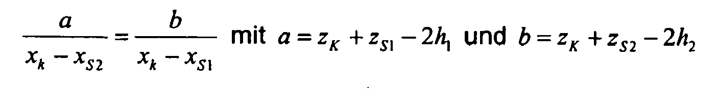
Mit diesem Zusammenhang kann ein Parameter in der Gleichung berechnet werden. Nach xk aufgelöst lautet diese Gleichung: 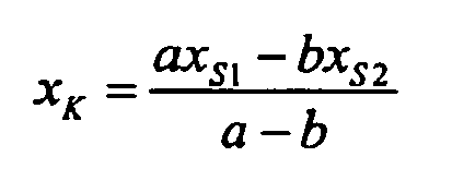
Die Rechnung für yk ergibt sich in analoger Weise durch Tauschen der Koordinatenrichtungen X und Y.The calculation for y k results in an analogous way by exchanging the coordinate directions X and Y.
Diese Gleichung wird für jedes Pixel der Kamera 1 aufgestellt. Die Bedingung für die Lösung des Gleichungssystems ist, dass sich alle Strahlen von Pixeln, die zu einer bestimmten Kamera 1 gehören, in einem Punkt schneiden. Das daraus entstehende Gleichungssystem wird durch einen geeigneten, bekannten Optimierungsalgorithmus, bspw. Newton-Gauss-Jordan, gelöst. Zur Vereinfachung der Optimierung können auch nur einige ausgewählte Pixel verwendet werden.This equation is set up for each pixel of the
Als vorteilhafte Startwerte für die Optimierung können geeignete Werte benutzt werden. So kann die Position aller Flachbildschirme 2 als Position des Pixels 0,0 grob vermessen und als Startwert verwendet werden. Gleiches gilt für die drei Raumwinkel jedes Monitors. Ferner werden die Höhen jeder Kamera Z sowie der Spiegelflächen 5, 6 h1 und h2 grob vermessen und als Startwert verwendet.As advantageous starting values for the optimization, suitable values can be used. Thus, the position of all
Für jeden Flachbildschirm 2 werden dann die X, Y und Z-Koordinate des Pixels (0,0) sowie die drei Raumwinkel seiner Lage optimiert. Entsprechendes gilt für die Höhen h1 und h2 der Spiegeloberflächen 5, 6 sowie der Höhe der Kameraposition Z. Als Ergebnis der Optimierung erhält man die korrekte Position und Lage jedes Flachbildschirms 2 sowie jeder Kamera 1. Zusätzlich ist für jedes Pixel, für das mindestens für eine Höhe eine gültige Messung durchgeführt wurde, der Punkt bekannt, auf den die Kamera in der Ebene z=0 blickt. Für die Reflexionen in den Höhen h1 und h2 ergibt sich folgende Beziehung 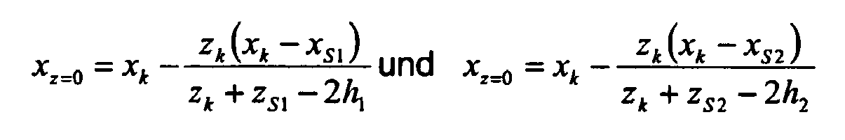
Diese Gleichungen ergeben sich aus der Betrachtung der Dreiecke gemäß
Da diese Rechnung für jedes Kamerapixel separat durchgeführt wird, ist nach der Kalibrierung für jedes Pixel der Kamera 1 die Blickrichtung im Raum bekannt, und zwar einschließlich der Objektivverzerrung, weil diese bei der Bildaufnahme ebenfalls berücksichtigt bzw. mitgemessen wurde. Anstelle der Modellierung der Kamera mit Verzerrungsmodellen wird bei dieser Vorgehensweise also für jedes Pixel explizit eine Blickrichtung bestimmt.Since this calculation is performed separately for each camera pixel, after the calibration for each pixel of the
Grundsätzlich könnte auch ein Verzerrungsmodell mit modelliert werden. Hierdurch ändert sich das zu optimierende Gleichungssystem dahingehend, dass diese Parameter zusätzlich auftauchen und optimiert werden, was einen erhöhten Rechenaufwand bedeutet.In principle, a distortion model could also be modeled. As a result, the system of equations to be optimized changes to the effect that these parameters additionally appear and are optimized, which means an increased amount of computation.
Weiterhin könnte für jede Spiegelhöhe eine im Prinzip bekannte Kalibrierung auf ein ebenes Muster durchgeführt werden, ohne die Tatsache zu berücksichtigen, dass die Kamera 1 in Wirklichkeit auf einen Spiegel des Musters 15 schaut. Dann ergibt sich für jede Spiegelhöhe h1 und h2 eine andere, virtuelle Kameraposition. Da jedoch bekannt ist, dass es sich in Wirklichkeit immer um dieselbe Kameraposition handelt und nur die Spiegelhöhen (bei exakt parallelen Spiegeloberflächen 5, 6) verschieden waren, kann ein Gleichungssystem aufgestellt werden, das diese Randbedingung nutzt. Durch Optimierung des Gleichungssystems erhält man dann die richtige Position der Kamera 1.Furthermore, a calibration known in principle could be performed on a plane pattern for each mirror height, without taking into account the fact that the
Diese Methode hat den Vorteil, dass die Kalibrierung in zwei Schritte zerlegt werden kann und für den ersten Schritt bekannte Standardmethoden benutzt werden können. Sie hat jedoch den Nachteil, dass man für den ersten Schritt nur das Muster 15 auf einem Musterträger 2 nutzen kann. Bei Anordnung mit mehreren Kameras 1 deckt ein Musterträger 2 in der Praxis aber nur einen Teil des Bildfeldes ab, und dies auch noch einseitig, d.h. nur auf einer Seite des Bildfeldes. Eine gute Kalibrierung lässt sich jedoch nur durchführen, wenn das Bildfeld einigermaßen gleichmäßig mit Musterpunkten belegt ist.This method has the advantage that the calibration can be divided into two steps and standard methods known for the first step can be used. However, it has the disadvantage that you can use only the
- 11
- Kameracamera
- 22
- Musterträger, FlachbildschirmPattern carrier, flat screen
- 33
- Objektobject
- 44
- Wannetub
- 55
- Spiegeloberfläche zur KalibrierungMirror surface for calibration
- 66
- Spiegeloberfläche zur KalibrierungMirror surface for calibration
- 77
- weltfestes Koordinatensystemworld-fixed coordinate system
- 88th
- Bild, KamerapixelPicture, camera pixels
- 99
- Markebrand
- 1010
- gemeinsames Koordinatensystemcommon coordinate system
- 1111
- abgedeckter Bereichcovered area
- 1212
- Bildfeld einer KameraImage field of a camera
- 1313
- Systemsystem
- 1414
- spiegelnde/reflektierende Oberflächereflective / reflective surface
- 1515
- Mustertemplate
- 1616
- Koordinatensystem der KameraCoordinate system of the camera
- 1717
- Koordinatensystem des MustersCoordinate system of the pattern
Claims (10)
- Method for calibrating a system for measuring the shape of a reflective surface, the system comprising a pattern carrier (2) comprising a pattern (15) for reflecting on a reflective surface (14) and a camera (1) for viewing, pixel by pixel, the pattern (15) which is reflected on the surface (14), characterised in that for calibrating the positions and the orientation of the camera (1) and pattern (15) and the viewing direction of each pixel of the camera (1), two large-area, planar reflective surfaces (5, 6), arranged in parallel, are used and the reflective surface (5, 6) is produced by a liquid.
- Method according to Claim 1, characterised in that the reflective surfaces (5, 6) are arranged at a height comparable with the reflective surface (14) to be measured.
- Method according to Claim 1 or 2, characterised in that the reflective surfaces (5, 6) are produced by two different filling levels of the liquid in a tray (4) and/or a displacement of the tray (4).
- Method according to one of Claims 1 to 3, characterised in that the pattern carrier (2) and the camera (1) are calibrated in a common coordinate system (10).
- Method according to one of Claims 1 to 4, characterised in that the liquid is configured to be sufficiently viscous and is preferably glycerin.
- System for measuring the shape of a reflective surface (14) comprising at least one pattern carrier (2) for producing a pattern (15) which may be reflected on the reflective surface (14), at least one camera (1) for viewing, pixel by pixel, the pattern (15) reflected on the surface (14) and an evaluation unit for evaluating the camera images (8) for determining the shape and/or calibration, characterised in that the system comprises a device (4) for arranging a large-area, planar reflective surface (5, 6), the reflective surface being formed by a liquid.
- System according to Claim 6, characterised in that the device for arranging the planar reflective surface (5, 6) is a tray (4).
- System according to Claim 6 or 7, characterised in that a pattern carrier (2) is a flat-screen monitor.
- System according to one of Claims 6 to 8, characterised in that a plurality of pattern carriers (2) are arranged in a quadrangle and cameras (1) are arranged at intersection points of the pattern carriers (2).
- System according to one of Claims 6 to 9, characterised in that the pattern carriers (2) are arranged so that they cover the spatial angles resulting from the reflective surface (14).
Applications Claiming Priority (2)
| Application Number | Priority Date | Filing Date | Title |
|---|---|---|---|
| DE102006015792A DE102006015792A1 (en) | 2006-04-05 | 2006-04-05 | Method and system for measuring the shape of a reflective surface |
| EP07711857A EP2002203B1 (en) | 2006-04-05 | 2007-03-08 | Method and system for measuring the shape of a reflective surface |
Related Parent Applications (2)
| Application Number | Title | Priority Date | Filing Date |
|---|---|---|---|
| EP07711857A Division EP2002203B1 (en) | 2006-04-05 | 2007-03-08 | Method and system for measuring the shape of a reflective surface |
| EP07711857.8 Division | 2007-03-08 |
Publications (3)
| Publication Number | Publication Date |
|---|---|
| EP2040026A2 EP2040026A2 (en) | 2009-03-25 |
| EP2040026A3 EP2040026A3 (en) | 2009-04-01 |
| EP2040026B1 true EP2040026B1 (en) | 2010-05-19 |
Family
ID=38042763
Family Applications (2)
| Application Number | Title | Priority Date | Filing Date |
|---|---|---|---|
| EP07711857A Not-in-force EP2002203B1 (en) | 2006-04-05 | 2007-03-08 | Method and system for measuring the shape of a reflective surface |
| EP08022163A Not-in-force EP2040026B1 (en) | 2006-04-05 | 2007-03-08 | Method and system for calibrating an apparatus for measuring the shape of a reflective surface |
Family Applications Before (1)
| Application Number | Title | Priority Date | Filing Date |
|---|---|---|---|
| EP07711857A Not-in-force EP2002203B1 (en) | 2006-04-05 | 2007-03-08 | Method and system for measuring the shape of a reflective surface |
Country Status (10)
| Country | Link |
|---|---|
| US (1) | US8064069B2 (en) |
| EP (2) | EP2002203B1 (en) |
| JP (2) | JP5334835B2 (en) |
| KR (2) | KR101318866B1 (en) |
| CN (2) | CN102305602B (en) |
| AT (2) | ATE475062T1 (en) |
| DE (3) | DE102006015792A1 (en) |
| ES (2) | ES2360239T3 (en) |
| TW (1) | TWI348018B (en) |
| WO (1) | WO2007115621A2 (en) |
Families Citing this family (37)
| Publication number | Priority date | Publication date | Assignee | Title |
|---|---|---|---|---|
| US8415648B2 (en) * | 2008-02-15 | 2013-04-09 | Pilkington Group Limited | Method of determination of glass surface shapes and optical distortion by reflected optical imaging |
| US8441532B2 (en) * | 2009-02-24 | 2013-05-14 | Corning Incorporated | Shape measurement of specular reflective surface |
| FR2951544A1 (en) | 2009-10-21 | 2011-04-22 | Saint Gobain | METHOD FOR ANALYZING THE QUALITY OF A GLAZING |
| EP2578990B1 (en) * | 2010-06-07 | 2022-07-20 | AGC Inc. | Shape measuring device, shape measuring method, and method for manufacturing glass plate |
| JP5920216B2 (en) | 2010-06-15 | 2016-05-18 | 旭硝子株式会社 | Shape measuring device, shape measuring method, and glass plate manufacturing method |
| FR2974414B1 (en) | 2011-04-22 | 2013-04-12 | Saint Gobain | METHOD FOR ANALYZING THE QUALITY OF A GLAZING |
| KR101893771B1 (en) * | 2012-05-10 | 2018-08-31 | 삼성전자주식회사 | Apparatus and method for processing 3d information |
| KR101501489B1 (en) * | 2013-11-12 | 2015-03-11 | 전자부품연구원 | Personal Virtual Flight Training Simulator Using a Collimated Display and Method Thereof |
| KR102233060B1 (en) * | 2013-12-19 | 2021-03-30 | 코닝 인코포레이티드 | Methods for determining a shape of a substantially cylindrical specular reflective surface |
| US9418411B2 (en) | 2014-04-22 | 2016-08-16 | The United States Of America, As Represented By The Secretary Of The Navy | System and method for sun glint correction of split focal plane visible and near infrared imagery |
| US10289895B2 (en) | 2014-10-21 | 2019-05-14 | Isra Surface Vision Gmbh | Method and device for determining a three-dimensional distortion |
| DE102014115331A1 (en) * | 2014-10-21 | 2016-04-21 | Isra Surface Vision Gmbh | Method and device for determining a three-dimensional distortion |
| DE102014115336A1 (en) * | 2014-10-21 | 2016-04-21 | Isra Surface Vision Gmbh | Method for determining a local power and device therefor |
| US9774093B2 (en) * | 2015-03-20 | 2017-09-26 | The Boeing Company | Automated reflector tuning systems and methdos |
| US9933251B2 (en) | 2015-06-26 | 2018-04-03 | Glasstech, Inc. | Non-contact gaging system and method for contoured glass sheets |
| US9470641B1 (en) | 2015-06-26 | 2016-10-18 | Glasstech, Inc. | System and method for measuring reflected optical distortion in contoured glass sheets |
| US9851200B2 (en) | 2015-06-26 | 2017-12-26 | Glasstech, Inc. | Non-contact gaging system and method for contoured panels having specular surfaces |
| US9841276B2 (en) | 2015-06-26 | 2017-12-12 | Glasstech, Inc. | System and method for developing three-dimensional surface information corresponding to a contoured glass sheet |
| US9952037B2 (en) * | 2015-06-26 | 2018-04-24 | Glasstech, Inc. | System and method for developing three-dimensional surface information corresponding to a contoured sheet |
| US9952039B2 (en) | 2015-06-26 | 2018-04-24 | Glasstech, Inc. | System and method for measuring reflected optical distortion in contoured panels having specular surfaces |
| US9958259B2 (en) | 2016-01-12 | 2018-05-01 | Canon Kabushiki Kaisha | Depth value measurement |
| US9996905B2 (en) * | 2016-03-16 | 2018-06-12 | Planet Labs, Inc. | Systems and methods for enhancing object visibility for overhead imaging |
| US10921118B2 (en) | 2016-07-27 | 2021-02-16 | Vehicle Service Group, Llc | Hybrid 3D optical scanning system |
| CN106441149B (en) * | 2016-09-05 | 2019-04-16 | 上海晶电新能源有限公司 | It is a kind of based on more range estimations away from tower secondary reflection mirror surface type detection system and method |
| TWI620926B (en) | 2016-11-04 | 2018-04-11 | 財團法人工業技術研究院 | Workpiece surface detection method and system using the same |
| CN107860333B (en) * | 2017-10-26 | 2020-01-24 | 常熟理工学院 | Automobile windshield detection device and automobile windshield detection system |
| WO2019147390A2 (en) * | 2018-01-26 | 2019-08-01 | Vehicle Hail Scan Systems, Llc | Vehicle surface scanning system |
| CN108444391B (en) * | 2018-03-16 | 2024-05-03 | 浙江大学 | Measuring device and measuring method for solid phase suspension height in multiphase transparent stirring kettle |
| PL3827246T3 (en) | 2018-07-24 | 2024-07-29 | Glasstech, Inc. | System and method for measuring a surface in contoured glass sheets |
| DE102019208474A1 (en) * | 2019-06-11 | 2020-12-17 | Micro-Epsilon Messtechnik Gmbh & Co. Kg | Method and system for optically measuring an object with a reflective and / or partially reflective surface and a corresponding measuring arrangement |
| EP3992575B1 (en) | 2019-06-28 | 2024-11-27 | Koh Young Technology Inc. | Apparatus and method for determining three-dimensional shape of an object |
| CN110360930A (en) * | 2019-08-29 | 2019-10-22 | 江苏集萃华科智能装备科技有限公司 | A kind of laser displacement normal sensor and its measurement method |
| KR20220158987A (en) | 2021-05-25 | 2022-12-02 | (주)와이엔디케이 | High speed Non contact Type Figure Inspection Method with Large area Freeform Surface Using Phase Measuring Deflectometry |
| DE102021123880A1 (en) | 2021-09-15 | 2023-03-16 | Isra Vision Gmbh | Method and device for detecting local defects on a reflective surface |
| KR102686830B1 (en) * | 2022-01-11 | 2024-07-19 | 한국기초과학지원연구원 | Calibration method and system for surface inspection device using Phase Measuring Deflectometry |
| US11867630B1 (en) | 2022-08-09 | 2024-01-09 | Glasstech, Inc. | Fixture and method for optical alignment in a system for measuring a surface in contoured glass sheets |
| CN119756245B (en) * | 2024-12-27 | 2025-10-28 | 东莞市铝宝金属科技有限公司 | Surface roughness measuring method for computer display card aluminum alloy die casting |
Family Cites Families (22)
| Publication number | Priority date | Publication date | Assignee | Title |
|---|---|---|---|---|
| US3137362A (en) * | 1961-03-27 | 1964-06-16 | Nelson Lab | Anechoic sonar calibration pool |
| US3799679A (en) | 1972-06-27 | 1974-03-26 | Ppg Industries Inc | Glass distortion scanning system |
| US4508452A (en) * | 1975-08-27 | 1985-04-02 | Robotic Vision Systems, Inc. | Arrangement for sensing the characteristics of a surface and determining the position of points thereon |
| US4294544A (en) | 1979-08-03 | 1981-10-13 | Altschuler Bruce R | Topographic comparator |
| US4876455A (en) * | 1988-02-25 | 1989-10-24 | Westinghouse Electric Corp. | Fiber optic solder joint inspection system |
| US5003615A (en) * | 1988-12-01 | 1991-03-26 | Harris Semiconductor Patents, Inc. | Optoelectronic system for determining surface irregularities of a workpiece having a nominally plane reflective surface |
| US5075560A (en) * | 1990-09-20 | 1991-12-24 | Eastman Kodak Company | Moire distance measurements using a grating printed on or attached to a surface |
| DE19643018B4 (en) * | 1996-10-18 | 2010-06-17 | Isra Surface Vision Gmbh | Method and device for measuring the course of reflective surfaces |
| US6166808A (en) * | 1996-12-24 | 2000-12-26 | U.S. Philips Corporation | Optical height meter, surface-inspection device provided with such a height meter, and lithographic apparatus provided with the inspection device |
| DE19757106A1 (en) | 1997-12-20 | 1999-06-24 | Juergen Prof Dr Massig | Topometer for reflecting surfaces |
| JPH11237305A (en) * | 1998-02-23 | 1999-08-31 | Mitsubishi Electric Corp | Optical axis deviation detector |
| JPH11257930A (en) * | 1998-03-13 | 1999-09-24 | Nidek Co Ltd | Three-dimensional shape measuring apparatus |
| JP3417377B2 (en) * | 1999-04-30 | 2003-06-16 | 日本電気株式会社 | Three-dimensional shape measuring method and apparatus, and recording medium |
| FR2817042B1 (en) | 2000-11-22 | 2003-06-20 | Saint Gobain | METHOD AND DEVICE FOR ANALYZING THE SURFACE OF A SUBSTRATE |
| US7115453B2 (en) * | 2001-01-29 | 2006-10-03 | Semiconductor Energy Laboratory Co., Ltd. | Semiconductor device and manufacturing method of the same |
| US6743700B2 (en) * | 2001-06-01 | 2004-06-01 | Semiconductor Energy Laboratory Co., Ltd. | Semiconductor film, semiconductor device and method of their production |
| DE10127304C5 (en) | 2001-06-06 | 2007-07-19 | Technische Universität Carolo-Wilhelmina Zu Braunschweig | Method and device for determining the three-dimensional contour of a specular surface of an object |
| JPWO2004013572A1 (en) * | 2002-08-01 | 2006-06-22 | 旭硝子株式会社 | Curved shape inspection method and apparatus |
| DE10345586B4 (en) * | 2003-09-29 | 2007-03-15 | BIAS - Bremer Institut für angewandte Strahltechnik GmbH | Method and device for determining the structure of a surface |
| JP4645068B2 (en) | 2004-06-04 | 2011-03-09 | 旭硝子株式会社 | Surface shape inspection method and inspection apparatus |
| JP2006003276A (en) * | 2004-06-18 | 2006-01-05 | Konica Minolta Sensing Inc | Three dimensional geometry measurement system |
| US7711182B2 (en) * | 2006-08-01 | 2010-05-04 | Mitsubishi Electric Research Laboratories, Inc. | Method and system for sensing 3D shapes of objects with specular and hybrid specular-diffuse surfaces |
-
2006
- 2006-04-05 DE DE102006015792A patent/DE102006015792A1/en not_active Withdrawn
-
2007
- 2007-03-08 ES ES08022163T patent/ES2360239T3/en active Active
- 2007-03-08 CN CN201110133405.9A patent/CN102305602B/en not_active Expired - Fee Related
- 2007-03-08 DE DE502007003867T patent/DE502007003867D1/en not_active Expired - Fee Related
- 2007-03-08 JP JP2009503444A patent/JP5334835B2/en active Active
- 2007-03-08 KR KR1020127030593A patent/KR101318866B1/en active Active
- 2007-03-08 AT AT07711857T patent/ATE475062T1/en active
- 2007-03-08 US US12/295,470 patent/US8064069B2/en active Active
- 2007-03-08 AT AT08022163T patent/ATE468522T1/en active
- 2007-03-08 EP EP07711857A patent/EP2002203B1/en not_active Not-in-force
- 2007-03-08 WO PCT/EP2007/001999 patent/WO2007115621A2/en not_active Ceased
- 2007-03-08 EP EP08022163A patent/EP2040026B1/en not_active Not-in-force
- 2007-03-08 CN CN2007800122454A patent/CN101416022B/en not_active Expired - Fee Related
- 2007-03-08 DE DE502007004485T patent/DE502007004485D1/en active Active
- 2007-03-08 ES ES07711857T patent/ES2348902T3/en active Active
- 2007-04-02 TW TW096111631A patent/TWI348018B/en not_active IP Right Cessation
-
2008
- 2008-11-05 KR KR1020087027187A patent/KR101266115B1/en not_active Expired - Fee Related
-
2011
- 2011-07-06 JP JP2011149786A patent/JP5623347B2/en active Active
Also Published As
| Publication number | Publication date |
|---|---|
| WO2007115621A3 (en) | 2007-12-06 |
| US8064069B2 (en) | 2011-11-22 |
| JP2009532685A (en) | 2009-09-10 |
| US20100060905A1 (en) | 2010-03-11 |
| DE502007004485D1 (en) | 2010-09-02 |
| DE102006015792A1 (en) | 2007-10-18 |
| KR101266115B1 (en) | 2013-05-27 |
| EP2002203A2 (en) | 2008-12-17 |
| EP2040026A2 (en) | 2009-03-25 |
| JP5334835B2 (en) | 2013-11-06 |
| WO2007115621A2 (en) | 2007-10-18 |
| JP5623347B2 (en) | 2014-11-12 |
| JP2011227093A (en) | 2011-11-10 |
| ATE475062T1 (en) | 2010-08-15 |
| KR20090031854A (en) | 2009-03-30 |
| ATE468522T1 (en) | 2010-06-15 |
| EP2002203B1 (en) | 2010-07-21 |
| CN101416022B (en) | 2012-05-23 |
| DE502007003867D1 (en) | 2010-07-01 |
| ES2348902T3 (en) | 2010-12-16 |
| TW200745505A (en) | 2007-12-16 |
| ES2360239T3 (en) | 2011-06-02 |
| CN101416022A (en) | 2009-04-22 |
| KR101318866B1 (en) | 2013-10-17 |
| CN102305602B (en) | 2014-10-01 |
| EP2040026A3 (en) | 2009-04-01 |
| CN102305602A (en) | 2012-01-04 |
| TWI348018B (en) | 2011-09-01 |
Similar Documents
| Publication | Publication Date | Title |
|---|---|---|
| EP2040026B1 (en) | Method and system for calibrating an apparatus for measuring the shape of a reflective surface | |
| DE69213749T2 (en) | METHOD AND DEVICE FOR THE SPOTUAL MEASUREMENT OF SPACE COORDINATES | |
| EP3278302B1 (en) | Motion-measuring system of a machine and method for operating the motion-measuring system | |
| EP1711777B2 (en) | Method for determining the position and the relative motion of an object in a space | |
| DE102014206309B4 (en) | System and method for obtaining offset images to be used for improved edge resolution | |
| DE10137241A1 (en) | Arrangement, for detecting and measuring objects, optically projects markers onto object, records partial views of object in global coordinate system using information re-detected markers | |
| EP0923705B1 (en) | Method and device for determining the spatial coordinates of objects | |
| DE19623172C1 (en) | Three-dimensional optical measuring method for object surface | |
| EP0449859B1 (en) | Process and device for observing moire patterns on test surfaces by moireing with phase shifts | |
| DE4212404B4 (en) | Apparatus and method for determining the spatial shape of an elongate member | |
| DE102017112976B4 (en) | Method for calibrating an optical arrangement of a coordinate measuring machine | |
| DE10127304C2 (en) | Method and device for determining the three-dimensional contour of a reflecting surface of an object | |
| DE102013014475A1 (en) | Method for calibration of optical measurement device for measuring geometric features of measuring object, involves executing static calibration and generating static calibration data or from evaluating- and control unit | |
| EP3799651B1 (en) | Method and system for optically measuring an object having a reflective and/or partially reflective surface and corresponding measuring arrangement | |
| DE102016220888A1 (en) | Reference plate and method for calibrating and / or checking a deflectometry sensor system | |
| DE10328523B4 (en) | Method and measuring device for non-contact measurement of a contour of a surface | |
| DE19534415A1 (en) | Method and device for detecting and measuring three-dimensional bodies or any surface | |
| DE102004033526A1 (en) | Analysis of at least partly reflecting surfaces involves varying relative orientation/position of object, pattern generation device and/or image receiver(s) for image reflected at surface, to obtain surface, especially geometry, information | |
| DE19509962A1 (en) | Three spatial components of three=dimensional object surface displacement vector field determn. method | |
| EP2031348B1 (en) | Surface inspection method for detecting surface defects and/or charting the surface topography | |
| DE102016218360A1 (en) | Calibration structure and calibration procedure for calibrating optical measuring instruments | |
| DE102004050020B4 (en) | Evaluation device and evaluation method for a crash test | |
| DE102010029627B4 (en) | Apparatus and method for determining the structure of a specular surface of an object | |
| DE102017009334B3 (en) | Method for testing an optical system | |
| DE102015117276B4 (en) | Method and device for measuring a test object with improved measuring accuracy |
Legal Events
| Date | Code | Title | Description |
|---|---|---|---|
| PUAI | Public reference made under article 153(3) epc to a published international application that has entered the european phase |
Free format text: ORIGINAL CODE: 0009012 |
|
| PUAL | Search report despatched |
Free format text: ORIGINAL CODE: 0009013 |
|
| AC | Divisional application: reference to earlier application |
Ref document number: 2002203 Country of ref document: EP Kind code of ref document: P |
|
| AK | Designated contracting states |
Kind code of ref document: A2 Designated state(s): AT BE BG CH CY CZ DE DK EE ES FI FR GB GR HU IE IS IT LI LT LU LV MC MT NL PL PT RO SE SI SK TR |
|
| AX | Request for extension of the european patent |
Extension state: AL BA HR MK RS |
|
| AK | Designated contracting states |
Kind code of ref document: A3 Designated state(s): AT BE BG CH CY CZ DE DK EE ES FI FR GB GR HU IE IS IT LI LT LU LV MC MT NL PL PT RO SE SI SK TR |
|
| AX | Request for extension of the european patent |
Extension state: AL BA HR MK RS |
|
| 17P | Request for examination filed |
Effective date: 20091001 |
|
| GRAP | Despatch of communication of intention to grant a patent |
Free format text: ORIGINAL CODE: EPIDOSNIGR1 |
|
| AKX | Designation fees paid |
Designated state(s): AT BE BG CH CY CZ DE DK EE ES FI FR GB GR HU IE IS IT LI LT LU LV MC MT NL PL PT RO SE SI SK TR |
|
| GRAS | Grant fee paid |
Free format text: ORIGINAL CODE: EPIDOSNIGR3 |
|
| GRAA | (expected) grant |
Free format text: ORIGINAL CODE: 0009210 |
|
| AC | Divisional application: reference to earlier application |
Ref document number: 2002203 Country of ref document: EP Kind code of ref document: P |
|
| AK | Designated contracting states |
Kind code of ref document: B1 Designated state(s): AT BE BG CH CY CZ DE DK EE ES FI FR GB GR HU IE IS IT LI LT LU LV MC MT NL PL PT RO SE SI SK TR |
|
| REG | Reference to a national code |
Ref country code: GB Ref legal event code: FG4D Free format text: NOT ENGLISH |
|
| REG | Reference to a national code |
Ref country code: CH Ref legal event code: EP |
|
| REG | Reference to a national code |
Ref country code: IE Ref legal event code: FG4D Free format text: LANGUAGE OF EP DOCUMENT: GERMAN |
|
| REF | Corresponds to: |
Ref document number: 502007003867 Country of ref document: DE Date of ref document: 20100701 Kind code of ref document: P |
|
| REG | Reference to a national code |
Ref country code: NL Ref legal event code: VDEP Effective date: 20100519 |
|
| LTIE | Lt: invalidation of european patent or patent extension |
Effective date: 20100519 |
|
| PG25 | Lapsed in a contracting state [announced via postgrant information from national office to epo] |
Ref country code: LT Free format text: LAPSE BECAUSE OF FAILURE TO SUBMIT A TRANSLATION OF THE DESCRIPTION OR TO PAY THE FEE WITHIN THE PRESCRIBED TIME-LIMIT Effective date: 20100519 Ref country code: SE Free format text: LAPSE BECAUSE OF FAILURE TO SUBMIT A TRANSLATION OF THE DESCRIPTION OR TO PAY THE FEE WITHIN THE PRESCRIBED TIME-LIMIT Effective date: 20100519 |
|
| PG25 | Lapsed in a contracting state [announced via postgrant information from national office to epo] |
Ref country code: IS Free format text: LAPSE BECAUSE OF FAILURE TO SUBMIT A TRANSLATION OF THE DESCRIPTION OR TO PAY THE FEE WITHIN THE PRESCRIBED TIME-LIMIT Effective date: 20100919 Ref country code: LV Free format text: LAPSE BECAUSE OF FAILURE TO SUBMIT A TRANSLATION OF THE DESCRIPTION OR TO PAY THE FEE WITHIN THE PRESCRIBED TIME-LIMIT Effective date: 20100519 Ref country code: SI Free format text: LAPSE BECAUSE OF FAILURE TO SUBMIT A TRANSLATION OF THE DESCRIPTION OR TO PAY THE FEE WITHIN THE PRESCRIBED TIME-LIMIT Effective date: 20100519 Ref country code: FI Free format text: LAPSE BECAUSE OF FAILURE TO SUBMIT A TRANSLATION OF THE DESCRIPTION OR TO PAY THE FEE WITHIN THE PRESCRIBED TIME-LIMIT Effective date: 20100519 |
|
| PG25 | Lapsed in a contracting state [announced via postgrant information from national office to epo] |
Ref country code: CY Free format text: LAPSE BECAUSE OF FAILURE TO SUBMIT A TRANSLATION OF THE DESCRIPTION OR TO PAY THE FEE WITHIN THE PRESCRIBED TIME-LIMIT Effective date: 20100609 Ref country code: PL Free format text: LAPSE BECAUSE OF FAILURE TO SUBMIT A TRANSLATION OF THE DESCRIPTION OR TO PAY THE FEE WITHIN THE PRESCRIBED TIME-LIMIT Effective date: 20100519 |
|
| REG | Reference to a national code |
Ref country code: IE Ref legal event code: FD4D |
|
| PG25 | Lapsed in a contracting state [announced via postgrant information from national office to epo] |
Ref country code: NL Free format text: LAPSE BECAUSE OF FAILURE TO SUBMIT A TRANSLATION OF THE DESCRIPTION OR TO PAY THE FEE WITHIN THE PRESCRIBED TIME-LIMIT Effective date: 20100519 Ref country code: DK Free format text: LAPSE BECAUSE OF FAILURE TO SUBMIT A TRANSLATION OF THE DESCRIPTION OR TO PAY THE FEE WITHIN THE PRESCRIBED TIME-LIMIT Effective date: 20100519 Ref country code: EE Free format text: LAPSE BECAUSE OF FAILURE TO SUBMIT A TRANSLATION OF THE DESCRIPTION OR TO PAY THE FEE WITHIN THE PRESCRIBED TIME-LIMIT Effective date: 20100519 Ref country code: IE Free format text: LAPSE BECAUSE OF FAILURE TO SUBMIT A TRANSLATION OF THE DESCRIPTION OR TO PAY THE FEE WITHIN THE PRESCRIBED TIME-LIMIT Effective date: 20100519 Ref country code: PT Free format text: LAPSE BECAUSE OF FAILURE TO SUBMIT A TRANSLATION OF THE DESCRIPTION OR TO PAY THE FEE WITHIN THE PRESCRIBED TIME-LIMIT Effective date: 20100920 |
|
| PG25 | Lapsed in a contracting state [announced via postgrant information from national office to epo] |
Ref country code: SK Free format text: LAPSE BECAUSE OF FAILURE TO SUBMIT A TRANSLATION OF THE DESCRIPTION OR TO PAY THE FEE WITHIN THE PRESCRIBED TIME-LIMIT Effective date: 20100519 Ref country code: RO Free format text: LAPSE BECAUSE OF FAILURE TO SUBMIT A TRANSLATION OF THE DESCRIPTION OR TO PAY THE FEE WITHIN THE PRESCRIBED TIME-LIMIT Effective date: 20100519 |
|
| PLBE | No opposition filed within time limit |
Free format text: ORIGINAL CODE: 0009261 |
|
| STAA | Information on the status of an ep patent application or granted ep patent |
Free format text: STATUS: NO OPPOSITION FILED WITHIN TIME LIMIT |
|
| 26N | No opposition filed |
Effective date: 20110222 |
|
| PG25 | Lapsed in a contracting state [announced via postgrant information from national office to epo] |
Ref country code: GR Free format text: LAPSE BECAUSE OF FAILURE TO SUBMIT A TRANSLATION OF THE DESCRIPTION OR TO PAY THE FEE WITHIN THE PRESCRIBED TIME-LIMIT Effective date: 20100820 |
|
| REG | Reference to a national code |
Ref country code: ES Ref legal event code: FG2A Ref document number: 2360239 Country of ref document: ES Kind code of ref document: T3 Effective date: 20110602 |
|
| REG | Reference to a national code |
Ref country code: DE Ref legal event code: R097 Ref document number: 502007003867 Country of ref document: DE Effective date: 20110221 |
|
| REG | Reference to a national code |
Ref country code: DE Ref legal event code: R119 Ref document number: 502007003867 Country of ref document: DE Ref country code: DE Ref legal event code: R409 Ref document number: 502007003867 Country of ref document: DE |
|
| PG25 | Lapsed in a contracting state [announced via postgrant information from national office to epo] |
Ref country code: MC Free format text: LAPSE BECAUSE OF NON-PAYMENT OF DUE FEES Effective date: 20110331 |
|
| REG | Reference to a national code |
Ref country code: CH Ref legal event code: PL |
|
| REG | Reference to a national code |
Ref country code: DE Ref legal event code: R409 Ref document number: 502007003867 Country of ref document: DE |
|
| PG25 | Lapsed in a contracting state [announced via postgrant information from national office to epo] |
Ref country code: MT Free format text: LAPSE BECAUSE OF FAILURE TO SUBMIT A TRANSLATION OF THE DESCRIPTION OR TO PAY THE FEE WITHIN THE PRESCRIBED TIME-LIMIT Effective date: 20100519 |
|
| PG25 | Lapsed in a contracting state [announced via postgrant information from national office to epo] |
Ref country code: CH Free format text: LAPSE BECAUSE OF NON-PAYMENT OF DUE FEES Effective date: 20110331 Ref country code: LI Free format text: LAPSE BECAUSE OF NON-PAYMENT OF DUE FEES Effective date: 20110331 |
|
| PGFP | Annual fee paid to national office [announced via postgrant information from national office to epo] |
Ref country code: CZ Payment date: 20130227 Year of fee payment: 7 |
|
| REG | Reference to a national code |
Ref country code: AT Ref legal event code: MM01 Ref document number: 468522 Country of ref document: AT Kind code of ref document: T Effective date: 20120308 |
|
| PG25 | Lapsed in a contracting state [announced via postgrant information from national office to epo] |
Ref country code: LU Free format text: LAPSE BECAUSE OF NON-PAYMENT OF DUE FEES Effective date: 20110308 |
|
| PG25 | Lapsed in a contracting state [announced via postgrant information from national office to epo] |
Ref country code: AT Free format text: LAPSE BECAUSE OF NON-PAYMENT OF DUE FEES Effective date: 20120308 |
|
| PG25 | Lapsed in a contracting state [announced via postgrant information from national office to epo] |
Ref country code: BG Free format text: LAPSE BECAUSE OF FAILURE TO SUBMIT A TRANSLATION OF THE DESCRIPTION OR TO PAY THE FEE WITHIN THE PRESCRIBED TIME-LIMIT Effective date: 20100819 |
|
| PG25 | Lapsed in a contracting state [announced via postgrant information from national office to epo] |
Ref country code: HU Free format text: LAPSE BECAUSE OF FAILURE TO SUBMIT A TRANSLATION OF THE DESCRIPTION OR TO PAY THE FEE WITHIN THE PRESCRIBED TIME-LIMIT Effective date: 20100519 |
|
| PG25 | Lapsed in a contracting state [announced via postgrant information from national office to epo] |
Ref country code: CZ Free format text: LAPSE BECAUSE OF NON-PAYMENT OF DUE FEES Effective date: 20140308 |
|
| PGFP | Annual fee paid to national office [announced via postgrant information from national office to epo] |
Ref country code: BE Payment date: 20150318 Year of fee payment: 9 |
|
| REG | Reference to a national code |
Ref country code: FR Ref legal event code: PLFP Year of fee payment: 10 |
|
| PGFP | Annual fee paid to national office [announced via postgrant information from national office to epo] |
Ref country code: TR Payment date: 20160225 Year of fee payment: 10 Ref country code: ES Payment date: 20160322 Year of fee payment: 10 |
|
| PGFP | Annual fee paid to national office [announced via postgrant information from national office to epo] |
Ref country code: GB Payment date: 20160322 Year of fee payment: 10 |
|
| PG25 | Lapsed in a contracting state [announced via postgrant information from national office to epo] |
Ref country code: BE Free format text: LAPSE BECAUSE OF NON-PAYMENT OF DUE FEES Effective date: 20160331 |
|
| PGFP | Annual fee paid to national office [announced via postgrant information from national office to epo] |
Ref country code: IT Payment date: 20160318 Year of fee payment: 10 |
|
| REG | Reference to a national code |
Ref country code: FR Ref legal event code: PLFP Year of fee payment: 11 |
|
| GBPC | Gb: european patent ceased through non-payment of renewal fee |
Effective date: 20170308 |
|
| PG25 | Lapsed in a contracting state [announced via postgrant information from national office to epo] |
Ref country code: GB Free format text: LAPSE BECAUSE OF NON-PAYMENT OF DUE FEES Effective date: 20170308 Ref country code: IT Free format text: LAPSE BECAUSE OF NON-PAYMENT OF DUE FEES Effective date: 20170308 |
|
| REG | Reference to a national code |
Ref country code: FR Ref legal event code: PLFP Year of fee payment: 12 |
|
| REG | Reference to a national code |
Ref country code: ES Ref legal event code: FD2A Effective date: 20180705 |
|
| PG25 | Lapsed in a contracting state [announced via postgrant information from national office to epo] |
Ref country code: ES Free format text: LAPSE BECAUSE OF NON-PAYMENT OF DUE FEES Effective date: 20170309 |
|
| PGFP | Annual fee paid to national office [announced via postgrant information from national office to epo] |
Ref country code: FR Payment date: 20200324 Year of fee payment: 14 |
|
| PG25 | Lapsed in a contracting state [announced via postgrant information from national office to epo] |
Ref country code: FR Free format text: LAPSE BECAUSE OF NON-PAYMENT OF DUE FEES Effective date: 20210331 |
|
| PG25 | Lapsed in a contracting state [announced via postgrant information from national office to epo] |
Ref country code: TR Free format text: LAPSE BECAUSE OF NON-PAYMENT OF DUE FEES Effective date: 20170308 |
|
| PGFP | Annual fee paid to national office [announced via postgrant information from national office to epo] |
Ref country code: DE Payment date: 20240327 Year of fee payment: 18 |
|
| REG | Reference to a national code |
Ref country code: DE Ref legal event code: R119 Ref document number: 502007003867 Country of ref document: DE |
|
| PG25 | Lapsed in a contracting state [announced via postgrant information from national office to epo] |
Ref country code: DE Free format text: LAPSE BECAUSE OF NON-PAYMENT OF DUE FEES Effective date: 20251001 |