EP1994788B1 - Noise-reducing directional microphone array - Google Patents
Noise-reducing directional microphone array Download PDFInfo
- Publication number
- EP1994788B1 EP1994788B1 EP07752770.3A EP07752770A EP1994788B1 EP 1994788 B1 EP1994788 B1 EP 1994788B1 EP 07752770 A EP07752770 A EP 07752770A EP 1994788 B1 EP1994788 B1 EP 1994788B1
- Authority
- EP
- European Patent Office
- Prior art keywords
- signal
- cardioid
- microphone
- noise
- signals
- Prior art date
- Legal status (The legal status is an assumption and is not a legal conclusion. Google has not performed a legal analysis and makes no representation as to the accuracy of the status listed.)
- Active
Links
- 230000001629 suppression Effects 0.000 claims description 65
- 230000006978 adaptation Effects 0.000 claims description 47
- 230000005236 sound signal Effects 0.000 claims description 37
- 238000000034 method Methods 0.000 claims description 32
- 238000012545 processing Methods 0.000 claims description 27
- 238000001914 filtration Methods 0.000 claims description 9
- 230000003247 decreasing effect Effects 0.000 claims description 2
- 230000003044 adaptive effect Effects 0.000 description 60
- 230000004044 response Effects 0.000 description 39
- 230000000875 corresponding effect Effects 0.000 description 28
- 230000006870 function Effects 0.000 description 26
- 238000010586 diagram Methods 0.000 description 19
- 238000001514 detection method Methods 0.000 description 18
- 230000001902 propagating effect Effects 0.000 description 18
- 238000003491 array Methods 0.000 description 15
- 230000008901 benefit Effects 0.000 description 10
- 238000005070 sampling Methods 0.000 description 10
- 238000005314 correlation function Methods 0.000 description 7
- 238000001228 spectrum Methods 0.000 description 7
- 238000013459 approach Methods 0.000 description 6
- 230000035945 sensitivity Effects 0.000 description 6
- 238000005311 autocorrelation function Methods 0.000 description 5
- 230000001934 delay Effects 0.000 description 5
- 230000003111 delayed effect Effects 0.000 description 5
- 230000001419 dependent effect Effects 0.000 description 5
- 238000013461 design Methods 0.000 description 5
- 239000012530 fluid Substances 0.000 description 5
- 230000014509 gene expression Effects 0.000 description 5
- 238000012935 Averaging Methods 0.000 description 4
- 230000000670 limiting effect Effects 0.000 description 4
- 238000010295 mobile communication Methods 0.000 description 4
- 238000012986 modification Methods 0.000 description 4
- 230000004048 modification Effects 0.000 description 4
- 238000009795 derivation Methods 0.000 description 3
- 230000025518 detection of mechanical stimulus involved in sensory perception of wind Effects 0.000 description 3
- 230000000694 effects Effects 0.000 description 3
- 238000011065 in-situ storage Methods 0.000 description 3
- 238000010606 normalization Methods 0.000 description 3
- 230000008569 process Effects 0.000 description 3
- 229920000535 Tan II Polymers 0.000 description 2
- 230000005534 acoustic noise Effects 0.000 description 2
- 238000004458 analytical method Methods 0.000 description 2
- 230000001427 coherent effect Effects 0.000 description 2
- 230000004069 differentiation Effects 0.000 description 2
- 238000009499 grossing Methods 0.000 description 2
- 239000000463 material Substances 0.000 description 2
- 230000002829 reductive effect Effects 0.000 description 2
- 238000003860 storage Methods 0.000 description 2
- 230000007704 transition Effects 0.000 description 2
- 101000822695 Clostridium perfringens (strain 13 / Type A) Small, acid-soluble spore protein C1 Proteins 0.000 description 1
- 101000655262 Clostridium perfringens (strain 13 / Type A) Small, acid-soluble spore protein C2 Proteins 0.000 description 1
- 101000655256 Paraclostridium bifermentans Small, acid-soluble spore protein alpha Proteins 0.000 description 1
- 101000655264 Paraclostridium bifermentans Small, acid-soluble spore protein beta Proteins 0.000 description 1
- 239000000654 additive Substances 0.000 description 1
- 230000000996 additive effect Effects 0.000 description 1
- 230000002238 attenuated effect Effects 0.000 description 1
- 238000005452 bending Methods 0.000 description 1
- 230000005540 biological transmission Effects 0.000 description 1
- 238000004891 communication Methods 0.000 description 1
- 238000011109 contamination Methods 0.000 description 1
- 238000012937 correction Methods 0.000 description 1
- 230000002596 correlated effect Effects 0.000 description 1
- 238000010219 correlation analysis Methods 0.000 description 1
- 238000000354 decomposition reaction Methods 0.000 description 1
- 238000006073 displacement reaction Methods 0.000 description 1
- 238000009429 electrical wiring Methods 0.000 description 1
- 230000005670 electromagnetic radiation Effects 0.000 description 1
- 230000005284 excitation Effects 0.000 description 1
- 239000000835 fiber Substances 0.000 description 1
- 239000006260 foam Substances 0.000 description 1
- 238000003780 insertion Methods 0.000 description 1
- 230000037431 insertion Effects 0.000 description 1
- 230000002452 interceptive effect Effects 0.000 description 1
- 238000002372 labelling Methods 0.000 description 1
- 238000012886 linear function Methods 0.000 description 1
- 230000007774 longterm Effects 0.000 description 1
- 238000004519 manufacturing process Methods 0.000 description 1
- 238000013507 mapping Methods 0.000 description 1
- 239000011159 matrix material Substances 0.000 description 1
- 230000005404 monopole Effects 0.000 description 1
- 230000036961 partial effect Effects 0.000 description 1
- 239000002245 particle Substances 0.000 description 1
- 238000013139 quantization Methods 0.000 description 1
- 238000004088 simulation Methods 0.000 description 1
- 239000007787 solid Substances 0.000 description 1
- 230000003595 spectral effect Effects 0.000 description 1
- 238000010183 spectrum analysis Methods 0.000 description 1
- 238000006467 substitution reaction Methods 0.000 description 1
- 230000001052 transient effect Effects 0.000 description 1
Images


Classifications
-
- H—ELECTRICITY
- H04—ELECTRIC COMMUNICATION TECHNIQUE
- H04R—LOUDSPEAKERS, MICROPHONES, GRAMOPHONE PICK-UPS OR LIKE ACOUSTIC ELECTROMECHANICAL TRANSDUCERS; DEAF-AID SETS; PUBLIC ADDRESS SYSTEMS
- H04R1/00—Details of transducers, loudspeakers or microphones
- H04R1/20—Arrangements for obtaining desired frequency or directional characteristics
- H04R1/32—Arrangements for obtaining desired frequency or directional characteristics for obtaining desired directional characteristic only
- H04R1/326—Arrangements for obtaining desired frequency or directional characteristics for obtaining desired directional characteristic only for microphones
-
- H—ELECTRICITY
- H04—ELECTRIC COMMUNICATION TECHNIQUE
- H04R—LOUDSPEAKERS, MICROPHONES, GRAMOPHONE PICK-UPS OR LIKE ACOUSTIC ELECTROMECHANICAL TRANSDUCERS; DEAF-AID SETS; PUBLIC ADDRESS SYSTEMS
- H04R25/00—Deaf-aid sets, i.e. electro-acoustic or electro-mechanical hearing aids; Electric tinnitus maskers providing an auditory perception
- H04R25/40—Arrangements for obtaining a desired directivity characteristic
- H04R25/407—Circuits for combining signals of a plurality of transducers
-
- G—PHYSICS
- G10—MUSICAL INSTRUMENTS; ACOUSTICS
- G10L—SPEECH ANALYSIS TECHNIQUES OR SPEECH SYNTHESIS; SPEECH RECOGNITION; SPEECH OR VOICE PROCESSING TECHNIQUES; SPEECH OR AUDIO CODING OR DECODING
- G10L21/00—Speech or voice signal processing techniques to produce another audible or non-audible signal, e.g. visual or tactile, in order to modify its quality or its intelligibility
- G10L21/02—Speech enhancement, e.g. noise reduction or echo cancellation
- G10L21/0208—Noise filtering
- G10L21/0216—Noise filtering characterised by the method used for estimating noise
-
- G—PHYSICS
- G10—MUSICAL INSTRUMENTS; ACOUSTICS
- G10L—SPEECH ANALYSIS TECHNIQUES OR SPEECH SYNTHESIS; SPEECH RECOGNITION; SPEECH OR VOICE PROCESSING TECHNIQUES; SPEECH OR AUDIO CODING OR DECODING
- G10L21/00—Speech or voice signal processing techniques to produce another audible or non-audible signal, e.g. visual or tactile, in order to modify its quality or its intelligibility
- G10L21/02—Speech enhancement, e.g. noise reduction or echo cancellation
- G10L21/0208—Noise filtering
- G10L21/0264—Noise filtering characterised by the type of parameter measurement, e.g. correlation techniques, zero crossing techniques or predictive techniques
-
- H—ELECTRICITY
- H04—ELECTRIC COMMUNICATION TECHNIQUE
- H04R—LOUDSPEAKERS, MICROPHONES, GRAMOPHONE PICK-UPS OR LIKE ACOUSTIC ELECTROMECHANICAL TRANSDUCERS; DEAF-AID SETS; PUBLIC ADDRESS SYSTEMS
- H04R3/00—Circuits for transducers, loudspeakers or microphones
- H04R3/005—Circuits for transducers, loudspeakers or microphones for combining the signals of two or more microphones
-
- H—ELECTRICITY
- H04—ELECTRIC COMMUNICATION TECHNIQUE
- H04R—LOUDSPEAKERS, MICROPHONES, GRAMOPHONE PICK-UPS OR LIKE ACOUSTIC ELECTROMECHANICAL TRANSDUCERS; DEAF-AID SETS; PUBLIC ADDRESS SYSTEMS
- H04R3/00—Circuits for transducers, loudspeakers or microphones
- H04R3/04—Circuits for transducers, loudspeakers or microphones for correcting frequency response
-
- G—PHYSICS
- G10—MUSICAL INSTRUMENTS; ACOUSTICS
- G10L—SPEECH ANALYSIS TECHNIQUES OR SPEECH SYNTHESIS; SPEECH RECOGNITION; SPEECH OR VOICE PROCESSING TECHNIQUES; SPEECH OR AUDIO CODING OR DECODING
- G10L21/00—Speech or voice signal processing techniques to produce another audible or non-audible signal, e.g. visual or tactile, in order to modify its quality or its intelligibility
- G10L21/02—Speech enhancement, e.g. noise reduction or echo cancellation
- G10L21/0208—Noise filtering
- G10L21/0216—Noise filtering characterised by the method used for estimating noise
- G10L2021/02161—Number of inputs available containing the signal or the noise to be suppressed
- G10L2021/02166—Microphone arrays; Beamforming
-
- H—ELECTRICITY
- H04—ELECTRIC COMMUNICATION TECHNIQUE
- H04R—LOUDSPEAKERS, MICROPHONES, GRAMOPHONE PICK-UPS OR LIKE ACOUSTIC ELECTROMECHANICAL TRANSDUCERS; DEAF-AID SETS; PUBLIC ADDRESS SYSTEMS
- H04R2410/00—Microphones
- H04R2410/01—Noise reduction using microphones having different directional characteristics
-
- H—ELECTRICITY
- H04—ELECTRIC COMMUNICATION TECHNIQUE
- H04R—LOUDSPEAKERS, MICROPHONES, GRAMOPHONE PICK-UPS OR LIKE ACOUSTIC ELECTROMECHANICAL TRANSDUCERS; DEAF-AID SETS; PUBLIC ADDRESS SYSTEMS
- H04R2410/00—Microphones
- H04R2410/07—Mechanical or electrical reduction of wind noise generated by wind passing a microphone
-
- H—ELECTRICITY
- H04—ELECTRIC COMMUNICATION TECHNIQUE
- H04R—LOUDSPEAKERS, MICROPHONES, GRAMOPHONE PICK-UPS OR LIKE ACOUSTIC ELECTROMECHANICAL TRANSDUCERS; DEAF-AID SETS; PUBLIC ADDRESS SYSTEMS
- H04R2430/00—Signal processing covered by H04R, not provided for in its groups
- H04R2430/20—Processing of the output signals of the acoustic transducers of an array for obtaining a desired directivity characteristic
- H04R2430/21—Direction finding using differential microphone array [DMA]
-
- H—ELECTRICITY
- H04—ELECTRIC COMMUNICATION TECHNIQUE
- H04R—LOUDSPEAKERS, MICROPHONES, GRAMOPHONE PICK-UPS OR LIKE ACOUSTIC ELECTROMECHANICAL TRANSDUCERS; DEAF-AID SETS; PUBLIC ADDRESS SYSTEMS
- H04R2430/00—Signal processing covered by H04R, not provided for in its groups
- H04R2430/20—Processing of the output signals of the acoustic transducers of an array for obtaining a desired directivity characteristic
- H04R2430/23—Direction finding using a sum-delay beam-former
Definitions
- the present invention relates to acoustics, and, in particular, to techniques for reducing wind-induced noise in microphone systems, such as those in hearing aids and mobile communication devices, such as laptop computers and cell phones.
- Wind-induced noise in the microphone signal input to mobile communication devices is now recognized as a serious problem that can significantly limit communication quality. This problem has been well known in the hearing aid industry, especially since the introduction of directionality in hearing aids.
- Wind-noise sensitivity of microphones has been a major problem for outdoor recordings. Wind noise is also now becoming a major issue for users of directional hearing aids as well as cell phones and hands-free headsets.
- a related problem is the susceptibility of microphones to the speech jet, or flow of air from the talker's mouth. Recording studios typically rely on special windscreen socks that either cover the microphone or are placed between the talker and the microphone.
- microphones are typically shielded by windscreens made of a large foam or thick fuzzy material. The purpose of the windscreen is to eliminate the airflow over the microphone's active element, but allow the desired acoustic signal to pass without any modification.
- EP-A 0652686 (Cezanne et al. ) describes a technique for adaptively generating a differential audio signal from two omnidirectional microphone signals. Copies of the two microphone signals are each delayed by the propagation delay between the two microphones and combined with copies of the undelayed signals to generate two cardioid signals. One cardioid signal is scaled using an adaptation factor that can be only positive. The scaled cardioid signal is combined with the other, unscaled cardioid signal to generate the differential audio signal.
- EP-A 1 653 768 (Fischer et al. ) describes a technique for adaptively generating a differential audio signal from two omnidirectional microphone signals. Copies of the two microphone signals are each delayed by one sample (z -1 ) and combined with copies of the undelayed signals to generate two cardioid signals. One cardioid signal is scaled using an adaptation factor that can be positive or negative. The scaled cardioid signal is combined with the other, unscaled cardioid signal to generate the differential audio signal.
- the present invention relates to a method for processing signals as claimed in claim 1 and an audio system for processing audio signals as claimed in claim 15.
- Certain embodiments of the present invention relate to a technique that combines a constrained microphone adaptive beamformer and a multichannel parametric noise suppression scheme to allow for a gradual transition from (i) a desired directional operation when noise and wind conditions are benign to (ii) non-directional operation with increasing amount of wind-noise suppression as the environment tends to higher wind-noise conditions.
- the technique combines the operation of a constrained adaptive two-element differential microphone array with a multi-microphone wind-noise suppression algorithm.
- the main result is the combination of these two technological solutions.
- a two-element adaptive differential microphone is formed that is allowed to adjust its directional response by automatically adjusting its beampattern to minimize wind noise.
- the adaptive beamformer output is fed into a multichannel wind-noise suppression algorithm.
- the wind-noise suppression algorithm is based on exploiting the knowledge that wind-noise signals are caused by convective airflow whose speed of propagation is much less than that of desired propagating acoustic signals. It is this unique combination of both a constrainedtwo-element adaptive differential beamformer with multichannel wind-noise suppression that offers an effective solution for mobile communication devices in varying acoustic environments.
- the present invention is a method for processing audio signals as claimed in claim 1.
- a differential microphone is a microphone that responds to spatial differentials of a scalar acoustic pressure field.
- the order of the differential components that the microphone responds to denotes the order of the microphone.
- a microphone that responds to both the acoustic pressure and the first-order difference of the pressure is denoted as a first-order differential microphone.
- One requisite for a microphone to respond to the spatial pressure differential is the implicit constraint that the microphone size is smaller than the acoustic wavelength.
- Differential microphone arrays can be seen directly analogous to finite-difference estimators of continuous spatial field derivatives along the direction of the microphone elements. Differential microphones also share strong similarities to superdirectional arrays used in electromagnetic antenna design.
- Fig. 1 illustrates a first-order differential microphone 100 having two closely spaced pressure (i.e., omnidirectional) microphones 102 spaced at a distance d apart, with a plane wave s ( t ) of amplitude S o and wavenumber k incident at an angle ⁇ from the axis of the two microphones.
- w 1 and w 2 are weighting values applied to the first and second microphone signals, respectively.
- Fig. 2(a) shows an example of the response for this case.
- the concentric rings in the polar plots of Figs. 2(a) and 2(b) are 10dB apart.
- Fig. 3 shows a combination of two omnidirectional microphones 302 to obtain back-to-back cardioid microphones.
- the back-to-back cardioid signals can be obtained by a simple modification of the differential combination of the omnidirectional microphones. See U.S. Patent No. 5,473,701 .
- Cardioid signals can be formed from two omnidirectional microphones by including a delay ( T ) before the subtraction (which is equal to the propagation time ( d / c ) between microphones for sounds impinging along the microphone pair axis).
- Fig. 4 shows directivity patterns for the back-to-back cardioids of Fig. 3 .
- the solid curve is the forward-facing cardioid
- the dashed curve is the backward-facing cardioid.
- a practical way to realize the back-to-back cardioid arrangement shown in Fig. 3 is to carefully choose the spacing between the microphones and the sampling rate of the A/D converter to be equal to some integer multiple of the required delay.
- the sampling rate By choosing the sampling rate in this way, the cardioid signals can be made simply by combining input signals that are offset by an integer number of samples. This approach removes the additional computational cost of interpolation filtering to obtain the required delay, although it is relatively simple to compute the interpolation if the sampling rate cannot be easily set to be equal to the propagation time of sound between the two sensors for on-axis propagation.
- Equation (7) has a frequency response that is a first-order high-pass, and the directional is omnidirectional.
- Fig. 6 shows the configuration of an adaptive differential microphone 600 as introduced in G.W. Elko and A.T. Nguyen Pong, "A simple adaptive first-order differential microphone," Proc. 1995 IEEE ASSP Workshop on Applications of Signal Proc. to Audio and Acoustics, Oct. 1995 , referred to herein as "Elko-2.”
- a plane-wave signal s ( t ) arrives at two omnidirectional microphones 602 at an angle ⁇ .
- the microphone signals are sampled at the frequency 1/ T by analog-to-digital (A/D) converters 604 and filtered by anti-aliasing low-pass filters 606.
- A/D analog-to-digital
- delays 608 and subtraction nodes 610 form the forward and backward cardioid signals c F (n) and c B (n) by subtracting one delayed microphone signal from the other undelayed microphone signal.
- delays 608 and subtraction nodes 610 form the forward and backward cardioid signals c F (n) and c B (n) by subtracting one delayed microphone signal from the other undelayed microphone signal.
- the spacing d and the sampling rate 1/ T such that the required delay for the cardioid signals is an integer multiple of the sampling rate.
- Multiplication node 612 and subtraction node 614 generate the unfiltered output signal y ( n ) as an appropriate linear combination of c F ( n ) and c B ( n ).
- the adaptation factor (i.e., weight parameter) ⁇ applied at multiplication node 612 allows a solitary null to be steered in any desired direction.
- C F j ⁇ ⁇ , d S j ⁇ ⁇ ⁇ e j ⁇ kd 2 ⁇ cos ⁇ - e - kd ⁇ 1 + cos ⁇ 2
- first-order recursive low-pass filter 616 can equalize the mentioned distortion reasonably well.
- ⁇ sin kd 2 ⁇ 1 + cos ⁇ n sin kd 2 ⁇ 1 - cos ⁇ n .
- the steepest-descent algorithm finds a minimum of the error surface E [ y 2 ( t )] by stepping in the direction opposite to the gradient of the surface with respect to the adaptive weight parameter ⁇ .
- the quantity that we want to minimize is the mean of y 2 ( t ) but the LMS algorithm uses the instantaneous estimate of the gradient. In other words, the expectation operation in Equation (15) is applied and the instantaneous estimate is used.
- the LMS algorithm is slightly modified by normalizing the update size and adding a regularization constant ⁇ . Normalization allows explicit convergence bounds for ⁇ to be set that are independent of the input power. Regularization stabilizes the algorithm when the normalized input power in c B becomes too small.
- ⁇ ⁇ becomes undefined.
- a practical way to handle this case is to limit the power ratio of the forward-to-back cardioid signals. In practice, limiting this ratio to a factor of 10 is sufficient.
- the intervals ⁇ [0,1] and ⁇ [1, ⁇ ] are mapped onto ⁇ [0.5 ⁇ , ⁇ ] and ⁇ [0,0.5 ⁇ ], respectively.
- the directivity pattern does not contain a null. Instead, for small
- with -1 ⁇ ⁇ ⁇ 0, a minimum occurs at ⁇ ⁇ ; the depth of which reduces with growing
- An adaptive algorithm 618 chooses ⁇ such that the energy of y( n ) in a certain exponential or sliding window becomes a minimum. As such, ⁇ should be constrained to the interval [-1,1].
- a null maymove into the front halfplane and suppress the desired signal.
- the adaptation selects a ⁇ equal to or bigger than zero.
- ⁇ would tend to values of less than 0 indicates the presence of uncorrelated signals at the two microphones.
- ⁇ can also use ⁇ to detect (1) wind noise and conditions where microphone self-noise dominates the input power to the microphones or (2) coherent signals that have a propagation speed much less than the speed of sound in the medium (such as coherent convected turbulence).
- Fig. 7 shows a block diagram of the back end 700 of a frequency-selective first-order differential microphone.
- subtraction node 714, low-pass filter 716, and adaptation block 718 are analogous to subtraction node 614, low-pass filter 616, and adaptation block 618 of Fig. 6 .
- filters 712 and 713 decompose the forward and backward cardioid signals as a linear combination of bandpass filters of a uniform filterbank.
- the uniform filterbank is applied to both the forward cardioid signal c F ( n ) and the backward cardioid signal c B ( n ), where m is the subband index number and ⁇ is the frequency.
- the forward and backward cardioid signals are generated in the time domain, as shown in Fig. 6 .
- the time-domain cardioid signals are then converted into a subband domain, e.g., using a multichannel filterbank, which implements the processing of elements 712 and 713.
- a different adaptation factor ⁇ is generated for each different subband, as indicated in Fig. 7 by the "thick" arrow from adaptation block 718 to element 713.
- H ( j ⁇ ) we realize H ( j ⁇ ) as a linear combination of band-pass filters of a uniform filterbank.
- the filterbank consists of M complex band-passes that are modulated versions of a low-pass filter W ( j ⁇ ). That filter is commonly referred to as prototype filter. See R.E. Crochiere and L.R. Rabiner, Multirate Digital Signal Processing, Prentice Hall, Englewood Cliffs, NJ, (1983 ), and P.P.
- the back-to-back cardioid power and cross-power can be related to the acoustic pressure field statistics.
- the array response is that of a hypercardioid, i.e., the first-order array that has the highest directivity index, which corresponds to the minimum power output for all first-order arrays in an isotropic noise field.
- Equation (22) can be reduced to Equation (26) as follows: ⁇ opt ⁇ - R 11 T - R 22 T R 11 0 + R 22 0 .
- Equation (26) It may seem redundant to include both terms in the numerator and the denominator in Equation (26), since one might expect the noise spectrum to be similar for both microphone inputs since they are so close together. However, it is quite possible that only one microphone element is exposed to the wind or turbulent jet from a talker's mouth, and, as such, it is better to keep the expression more general.
- a simple model for the electronics and wind-noise signals would be the output of a single-pole low-pass filter operating on a wide-sense-stationary white Gaussian signal.
- Equation (30) is also valid for the case of only a single microphone exposed to the wind noise, since the power spectrum of the exposed microphone will dominate the numerator and denominator of Equation (26). Actually, this solution shows a limitation of the use of the back-to-back cardioid arrangement for this one limiting case. If only one microphone was exposed to the wind, the best solution is obvious: pick the microphone that does not have any wind contamination. A more general approach to handling asymmetric wind conditions is described in the next section.
- Equation (30) From the results given in Equation (30), it is apparent that, to minimize wind noise, microphone thermal noise, and circuit noise in a first-order differential array, one should allow the differential array to attain an omnidirectional pattern. At first glance, this might seem counterintuitive since an omnidirectional pattern will allow more spatial noise into the microphone output. However, if this spatial noise is wind noise, which is known to have a short correlation length, an omnidirectional pattern will result in the lowest output power as shown by Equation (30). Likewise, when there is no or very little acoustic excitation, only the uncorrelated microphone thermal and electronic noise is present, and this noise is also minimized by setting ⁇ ⁇ -1, as derived in Equation (30).
- Equation (32) ⁇ 2 ⁇ m 2 2 t - 2 ⁇ ⁇ ⁇ 1 - ⁇ ⁇ m 1 t ⁇ m 2 t + 1 - ⁇ 2 ⁇ m 1 2 t
- Equation (34) the derivative of Equation (34) is set equal to 0.
- a more-interesting case is one that covers a model of the case of a desired signal that has delay and attenuation between the microphones with independent (or less restrictively uncorrelated) additive noise.
- the delay, ⁇ is the time that it takes for the acoustic signal x ( t ) to travel between the two microphones, which is dependent on the microphone spacing and the angle that the acoustic signal is propagating relative to the microphone axis.
- Equation (41) the optimal combining coeffcient ⁇ opt is given by Equation (41) as follows: ⁇ opt ⁇ 1 + ⁇ ⁇ R xx 0 + R n 1 ⁇ n 1 0 1 + ⁇ 2 ⁇ R xx 0 + R n 1 ⁇ n 1 0 + R n 2 ⁇ n 2 0
- the optimum combiner will move towards the microphone with the lower power. Although this is what is desired when there is asymmetric wind noise, it is desirable to select the higher-power microphone for the wind noise-free case. In order to handle this specific case, it is desirable to form a robust wind-noise detector that is immune to the nearfield effect. This topic is covered in a later section.
- the sensitivity of differential microphones is proportional to k ", where
- the speed of the convected fluid perturbations is much less that the propagation speed for radiating acoustic signals.
- the difference between propagating speeds is typically by two orders of magnitude.
- the sensitivity of differential microphones is proportional to k n , the output signal ratio of turbulent signals will be two orders of magnitude greater than the output signal ratio of propagating acoustic signals for equivalent levels of pressure fluctuation.
- a main goal of incoherent noise and turbulent wind-noise suppression is to determine what frequency components are due to noise and/or turbulence and what components are desired acoustic signals.
- the results of the previous sections can be combined to determine how to proceed.
- U.S. Patent No. 7,171,008 proposes a noise-signal detection and suppression algorithm based on the ratio of the difference-signal power to the sum-signal power. If this ratio is much smaller than the maximum predicted for acoustic signals (signals propagating along the axis of the microphones), then the signal is declared noise and/or turbulent, and the signal is used to update the noise estimation.
- the gain that is applied can be (i) the Wiener filter gain or (ii) by a general weighting (less than 1) that (a) can be uniform across frequency or (b) can be any desired function of frequency.
- U.S. Patent No. 7,171,008 proposed to apply a suppression weighting function on the output of a two-two-microphone array based on the enforcement of the difference-to-sum power ratio. Since wind noise results in a much larger ratio, suppressing by an amount that enforces the ratio to that of pure propagating acoustic signals traveling along the axis of the microphones results in an effective solution.
- the power ratio R( ⁇ ) is much greater (by the ratio of the different propagation speeds). Also, since the convective-turbulence spatial-correlation function decays rapidly and this term becomes dominant when turbulence (or independent sensor self-noise is present), the resulting power ratio tends towards unity, which is even greater than the ratio difference due to the speed of propagation difference.
- Equations (46) and (47) led to a relatively simple algorithm for suppression of airflow turbulence and sensor self-noise.
- the rapid decay of spatial coherence results in the relative powers between the differences and sums of the closely spaced pressure (zero-order) microphones being much larger than for an acoustic planewave propagating along the microphone array axis.
- Fig.10 shows the difference-to-sum power ratio for a pair of omnidirectional microphones spaced at 2 cm in a convective fluid flow propagating at 5 m/s.
- Equation (47) If sound arrives from off-axis from the microphone array, then the ratio of the difference-to-sum power levels for acoustic signals becomes even smaller as shown in Equation (47). Note that it has been assumed that the coherence decay is similar in all directions (isotropic). The power ratio R maximizes for acoustic signals propagating along the microphone axis. This limiting case is the key to the proposed wind-noise detection and suppression algorithm described in U.S. Patent No. 7,171,008 .
- the proposed suppression gain G ( ⁇ ) is stated as follows: If the measured ratio exceeds that given by Equation (46), then the output signal power is reduced by the difference between the measured power ratio and that predicted by Equation (46).
- R m ( ⁇ ) is the measured difference-to-sum signal power ratio.
- the directivity determined solely by the value of R ( ⁇ ) is set to a fixed value.
- the value of ⁇ is selected by the designer to have a fixed value.
- the constrained or unconstrained value of ⁇ ( ⁇ ) can be used to determine if there is wind noise or uncorrelated noise in the microphone channels.
- Table II shows appropriate settings for the directional pattern and electronic windscreen operation as a function of the constrained or unconstrained value of ⁇ ( ⁇ ) from the adaptive beamformer.
- the suppression function is determined solely from the value of the constrained (or even possibly unconstrained) ⁇ , where the constrained ⁇ is such that -1 ⁇ ⁇ ⁇ 1.
- the value of ⁇ utilized by the beamformer can be either a fixed value that the designer would choose, or allowed to be adaptive.
- Wind-Noise Suppression by Electronic Windscreen Algorithm Determined by the Adaptive Beamformer Value of ⁇ Acoustic Conditions ⁇ Directional Pattern Electronic Windscreen Operation No wind 0 ⁇ ⁇ ⁇ 1 General cardioid No suppression ( ⁇ fixed or adaptive) Slight wind -1 ⁇ ⁇ ⁇ 0 Subcardioid Increasing suppression High wind -1 Omnidirectional Maximum suppression
- Fig. 12 shows a block diagram of a microphone amplitude calibration system 1200 for a set of microphones 1202 .
- one microphone microphone 1202-1 in the implementation of Fig. 12
- Subband filterbank 1204 breaks each microphone signal into a set of subbands.
- the subband filterbank can be either the same as that used for the noise-suppression algorithm or some other filterbank.
- For speech one can choose a band that covers the frequency range from 500 Hz to about 1 kHz. Other bands can be chosen depending on how wide the frequency averaging is desired.
- an envelope detector 1206 For each different subband of each different microphone signal, an envelope detector 1206 generates a measure of the subband envelope. For each non-reference microphone (each of microphones 1202-2, 1202 3, ... in the implementation of Fig. 12 ), a single-tap adaptive filter 1208 scales the average subband envelope corresponding to one or more adjacent subbands based on a filter coefficient w j that is adaptively updated to reduce the magnitude of an error signal generated at a difference node 1210 and corresponding to the difference between the resulting filtered average subband envelope and the corresponding average reference subband envelope from envelope detector 1206-1 .
- the resulting filter coefficient w j represents an estimate of the relative magnitude difference between the corresponding subbands of the particular non-reference microphone and the corresponding subbands of the reference microphone.
- the time-varying filter coefficients w j for each microphone and each set of one or more adjacent subbands are applied to control block 1212 , which applies those filter coefficients to three different low-pass filters that generate three different filtered weight values: an "instantaneous" low-pass filter LP i having a high cutoff frequency (e.g., about 200 Hz) and generating an "instantaneous" filtered weight value w i j , a "fast" low-pass filter LP f having an intermediate cutoff frequency (e.g., about 20 Hz) and generating a "fast” filtered weight value w f i , and a "slow" low-pass filter LP s having a low cutoff frequency (e.g., about 2 Hz) and generating a "slow” filtered weight value w s j .
- an "instantaneous" low-pass filter LP i having a high cutoff frequency (e.g., about 200 Hz) and generating an
- the instantaneous weight values w i j are preferably used in a wind-detection scheme, the fast weight values w f i are preferably used in an electronic wind-noise suppression scheme, and the slow weight values w s j are preferably used in the adaptive beamformer.
- the exemplary cutoff frequencies for these lowpass filters are just suggestions and should not be considered optimal values.
- Fig. 12 illustrates the low-pass filtering applied by control block 1212 to the filter coefficients w 2 for the second microphone. Control block 1212 applies analogous filtering to the filter coefficients corresponding to the other non-reference microphones.
- control block 1212 also receives wind-detection signals 1214 and nearfield-detection signals 1216 .
- Each wind-detection signal 1214 indicates whether the microphone system has detected the presence of wind in one or more microphone subbands, while each nearfield-detection signal 1216 indicates whether the microphone system has detected the presence of a nearfield acoustic source in one or more microphone subbands.
- control block 1212 if, for a particular microphone and for a particular subband, either the corresponding wind-detection signal 1214 indicates presence of wind or the corresponding nearfield-detection signal 1216 indicates presence of a nearfield source, then the updating of the filtered weight values for the corresponding microphone and the corresponding subband is suspended for the long-term beamformer weights, thereby maintaining those weight factors at their most-recent values until both wind and a nearfield source are no longer detected and the updating of the weight factors by the low-pass filters is resumed.
- a net effect of this calibration-inhibition scheme is to allow beamformer weight calibration only when farfield signals are present without wind.
- wind-detection signal 1214 by a robust wind-detection scheme based on computed wind metrics in different subbands is described in further detail below with respect to Figs. 13 and 14 .
- nearfield source detection is based on a comparison of the output levels from the underlying back-to-back cardioid signals that are the basis signals used in the adaptive beamformer. For a headset application, where the array is pointed in the direction of the headset wearer's mouth, a nearfield source is detected by comparing the power differences between forward-facing and rearward-facing synthesized cardioid microphone patterns.
- these cardioid microphone patterns can be realized as general forward and rearward beampatterns not necessarily having a null along the microphone axis. These beampatterns can be variable so as to minimize the headset wearer's nearfield speech in the rearward-facing synthesized beamformer. Thus, the rearward-facing beamformer may have a nearfield null, but not a null in the farfield. If the forward cardioid signal (facing the mouth) greatly exceeds the rearward cardioid signal, then a nearfield source is declared. The power differences between the forward and rearward cardioid signals can also be used to adjust the adaptive beamformer speed.
- the speed of operation of the adaptive beamformer can be decreased by reducing the magnitude of the update step-size ⁇ in Equation (17).
- Figs. 13 and 14 show block diagrams of wind-noise detectors that can effectively handle operation of the microphone array in the nearfield of a desired source.
- Figs. 13 and 14 represent wind-noise detection for three adjacent subbands of two microphones: reference microphone 1202-1 and non-reference microphone 1202-2 of Fig. 12 .
- Analogous processing can be applied for other subbands and/or additional non-reference microphones.
- Front-end calibration 1303 represents the processing of Fig. 12 associated with the generation of filter coefficients w 2 .
- subband filterbank 1304 of Fig. 13 maybe the same as or different from subband filterbank 1204 of Fig. 12 .
- the resulting difference values are scaled at scalar amplifiers 1310 based on scale factors s k that depend on the spacing between the two microphones (e.g., the greater the microphone spacing and greater the frequency of the subband, the greater the scale factor).
- the magnitudes of the resulting scaled, subband-coefficient differences are generated at magnitude detectors 1312 . Each magnitude constitutes a measure of the difference-signal power for the corresponding subband.
- the three difference-signal power measures are summed at summation block 1314 , and the resulting sum is normalized at normalization amplifier 1316 based on the summed magnitude of all three subbands for both microphones 1282-1 and 1202-2 .
- This normalization factor constitutes a measure of the sum-signal power for all three subbands.
- the resulting normalized value constitutes a measure of the effective difference-to-sum power ratio (described previously) for the three subbands.
- This difference-to-sum power ratio is thresholded at threshold detector 1318 relative to a specified corresponding ratio threshold level. If the difference-to-sum power ratio exceeds the ratio threshold level, then wind is detected for those three subbands, and control block 1212 suspends updating of the corresponding weight factors by the low-pass filters for those three subbands.
- Fig. 14 shows an alternative wind-noise detector 1400 , in which a difference-to-sum power ratio R k is estimated for each of the three different subbands at ratio generators 1412 , and the maximum power ratio (selected at max block 1414 ) is applied to threshold detector 1418 to determine whether wind-noise is present for all three subbands.
- the scalar amplifiers 1310 and 1410 can be used to adjust the frequency equalization between the difference and sum powers.
- Audio system 1500 is a two-element microphone array that combines adaptive beamforming with wind-noise suppression to reduce wind noise induced into the microphone output signals.
- audio system 1500 comprises (i) two (e.g., omnidirectional) microphones 1502(1) and 1502(2) that generate electrical audio signals 1503(1) and 1503(2) , respectively, in response to incident acoustic signals and (ii) signal-processing elements 1504-1518 that process the electrical audio signals to generate an audio output signal 1519 , where elements 1504-1514 form an adaptive beamformer, and spatial-noise suppression (SNS) processor 1518 performs wind-noise suppression as defined in U.S. patent no. 7,171,008 and in PCT patent application PCT/US06/44427 .
- SNS spatial-noise suppression
- Calibration filter 1504 calibrates both electrical audio signals 1503 relative to one another. This calibration can either be amplitude calibration, phase calibration, or both.
- U.S. patent no. 7,171,008 describes some schemes to implement this calibration in situ.
- a first set of weight factors are applied to microphone signals 1503(1) and 1503(2) to generate first calibrated signals 1505(1) and 1505(2) for use in the adaptive beamformer, while a second set of weight factors are applied to the microphone signals to generate second calibrated signals 1520(1) and 1520(2) for use in SNS processor 1518 .
- the first set of weight factors are the weight factors w s j generated by control block 1212
- the second set of weight factors are the weight factors w f j generated by control block 1212 .
- first calibrated signals 1505(1) and 1505(2) are delayed by delay blocks 1506(1) and 1506(2) .
- first calibrated signal 1505(1) is applied to the positive input of difference node 1508(2)
- first calibrated signal 1505(2) is applied to the positive input of difference node 1508(1) .
- the delayed signals 1507(1) and 1507(2) from delay nodes 1506(1) and 1506(2) are applied to the negative inputs of difference nodes 1508(1) and 1508(2) , respectively.
- Each difference node 1508 generates a difference signal 1509 corresponding to the difference between the two applied signals.
- Difference signals 1509 are front and back cardioid signals that are used by LMS (least mean square) block 1510 to adaptively generate control signal 1511 , which corresponds to a value of adaptation factor ⁇ that minimizes the power of output signal 1519 .
- LMS block 1510 limits the value of ⁇ to a region of -1 ⁇ ⁇ ⁇ 0 .
- One modification of this procedure would be to set ⁇ to a fixed, non-zero value, when the computed value for ⁇ is greater that 0. By allowing for this case, ⁇ would be discontinuous and would therefore require some smoothing to remove any switching transient in the output audio signal.
- Difference signal 1509(1) is applied to the positive input of difference node 1514
- difference signal 1509(2) is applied to gain element 1512 , whose output 1513 is applied to the negative input of difference node 1514 .
- Gain element 1512 multiplies the rear cardioid generated by difference node 1508(2) by a scalar value computed in the LMS block to generate the adaptive beamformer output.
- Difference node 1514 generates a difference signal 1515 corresponding to the difference between the two applied signals 1509(1) and 1513 .
- first-order low-pass filter 1516 applies a low-pass filter to difference signal 1515 to compensate for the ⁇ high-pass that is imparted by the cardioid beamformers.
- the resulting filtered signal 1517 is applied to spatial-noise suppression processor 1518 .
- SNS processor 1518 implements a generalized version of the electronic windscreen algorithm described in U.S. Patent No. 7,171,008 and PCT patent application PCT/US06/44427 as a subband-based processing function.
- SNS block 1518 allows more-precise tailoring of the desired operation of the suppression as a function of the log of the measured power ratio
- Processing within SNS block 1518 is dependent on second calibrated signals 1520 from both microphones as well as the filtered output signal 1517 from the adaptive beamformer.
- SNS block 1518 can also use the ⁇ control signal 1511 generated by LMS block 1510 to further refine and control the wind-noise detector and the overall suppression to the signal achieved by the SNS block.
- SNS 1518 implements equalization filtering on second calibrated signals 1520 .
- Fig. 16 shows a block diagram of an audio system 1600 , according to an embodiment of the present invention.
- Audio system 1600 is similar to audio system 1500 of Fig. 15 , except that, instead of receiving the calibrated microphone signals, SNS block 1618 receives sum signal 1621 and difference signal 1623 generated by sum and different nodes 1620 and 1622 , respectively.
- Sum node 1620 adds the two cardioid signals 1609(1) and 1609(2) to generate sum signal 1621, corresponding to an omnidirectional response, while difference node 1622 subtracts the two cardioid signals to generate difference signal 1623 , corresponding to a dipole response.
- the low-pass filtered sum 1617 of the two cardioid signals 1609(1) and 1613 is equal to a filtered addition of the two microphone input signals 1603(1) and 1603(2) .
- the low-pass filtered difference 1623 of the two cardioid signals is equal to a filtered subtraction of the two microphone input signals.
- One difference between audio system 1500 of Fig. 15 and audio system 1600 of Fig. 16 is that SNS block 1518 of Fig. 15 receives the second calibrated microphone signals 1520(1) and 1520(2) , while audio system 1600 derives sum and difference signals 1621 and 1623 from the computed cardioid signals 1609(1) and 1609(2) . While the derivation in audio system 1600 might not be useful with nearfield sources, one advantage to audio system 1600 is that, since sum and difference signals 1621 and 1623 have the same frequency response, they do not need to be equalized.
- Fig. 17 shows a block diagram of an audio system 1700 , according to yet another embodiment of the present invention.
- Audio system 1700 is similar to audio system 1500 of Fig. 15 , where SNS block 1518 of Fig. 15 is implemented using time-domain filterbank 1724 and parametric high-pass filter 1726 . Since the spectrum of wind noise is dominated by low frequencies, audio system 1700 implements filterbank 1724 as a set of time-domain band-pass filters to compute the power ratio R as a function of frequency. Having computed in this fashion allows for dynamic control of parametric high-pass filter 1726 in generating output signal 1719.
- filterbank 1724 generates cutoff frequency f c , which high-pass filter 1726 uses as a threshold to effectively suppress the low-frequency wind-noise components.
- the algorithm to compute the desired cutoff frequency uses the power ratio as well as the adaptive beamformer parameter ⁇ . When ⁇ is less than 1 but greater than 0, the cutoff frequency is set at a low value. However, as ⁇ goes negative towards the limit at -1, this indicates that there is a possibility of wind noise. Therefore, in conjunction with the power ratio a high-pass filter is progressively applied when both ⁇ goes negative and exceeds some defined threshold. This implementation can be less computationally demanding than a full frequency-domain algorithm, while allowing for significantly less time delay from input to output. Note that, in addition to applying low-pass filtering, block LI applies a delay to compensate for the processing time of filterbank 1724 .
- Fig. 18 shows a block diagram of an audio system 1800 , according to still another embodiment of the present invention.
- Audio system 1800 is analogous to audio system 1700 of Fig. 17 , where both the adaptive beamforming and the spatial-noise suppression are implemented in the frequency domain.
- audio system 1800 has M -tap FFT-based subband filterbank 1824, which converts each time-domain audio signal 1803 into (1+ M /2) frequency-domain signals 1825 .
- Moving the subband filter decomposition to the output of the microphone calibration results in multiple, simultaneous, adaptive, first-order beamformers, where SNS block 1818 implements processing analogous to that of SNS 1518 of Fig.
- a subband implementation allows the microphone to tend towards omnidirectional at the dominant low frequencies when wind is present, and remain directional at higher frequencies where the interfering noise source might be dominated by acoustic noise signals.
- processing of the sum and difference signals can alternatively be accomplished in the frequency domain by directly using the two back-to-back cardioid signals.
- the delay T 1 is equal to the delay applied to one sensor of the first-order sections, and T 2 is the delay applied to the combination of the two first-order sections.
- the subscript on the variable Y is used to designate that the system response is a second-order differential response.
- the magnitude of the wavevector k is
- Equation (51) contains the array directional response, composed of a monopole term, a first-order dipole term cos ⁇ that resolves the component of the acoustic particle velocity along the sensor axis, and a linear quadruple term cos 2 ⁇ .
- the second-order array has a second-order differentiator frequency dependence (i.e., output increases quadratically with frequency). This frequency dependence is compensated in practice by a second-order lowpass filter.
- the topology shown in Fig. 19 can be extended to any order as long as the total length of the array is much smaller than the acoustic wavelength of the incoming desired signals.
- the array directivity is of major interest.
- the last product term expresses the angular dependence of the array, the terms that precede it determine the sensitivity of the array as a function of frequency, spacing, and time delay.
- the last product term contains the angular dependence of the array.
- the directionality of an N th -order differential array is the product of N first-order directional responses, which is a restatement of the pattern multiplication theorem in electroacoustics.
- the ⁇ i are constrained as 0 ⁇ ⁇ i ⁇ 0.5
- the directional response of the N th -order array shown in Equation (54) contains N zeros (or nulls) at angles between 90° ⁇ ⁇ ⁇ 180°.
- Fig. 19 One possible realization of the second-order adaptive differential array variable time delays T 1 and T 2 is shown in Fig. 19 .
- This solution generates any time delay less than or equal to d i / c .
- the computational requirements needed to realize the general delay by interpolation filtering and the resulting adaptive algorithms may be unattractive for an extremely low complexity real-time implementation.
- Another way to efficiently implement the adaptive differential array is to use an extension of the back-to-back cardioid configuration using a sampling rate whose sampling period is an integer multiple or divisor of the time delay for on-axis acoustic waves to propagate between the microphones, as described earlier.
- Fig. 20 shows a schematic implementation of an adaptive second-order array differential microphone utilizing fixed delays and three omnidirectional microphone elements.
- the back-to-back cardioid arrangement for a second-order array can be implemented as shown in Fig. 20 .
- This topology can be followed to extend the differential array to any desired order.
- One simplification utilized here is the assumption that the distance d 1 between microphones m1 and m2 is equal to the distance d 2 between microphones m2 and m3, although this is not necessary to realize the second-order differential array.
- This simplification does not limit the design but simplifies the design and analysis.
- There are some other benefits to the implementation that result by assuming that all d i are equal.
- One major benefit is the need for only one unique delay element.
- this delay can be realized as one sampling period, but, since fractional delays are relatively easy to implement, this advantage is not that significant.
- the sampling period equal to d / c
- the back-to-back cardioid microphone outputs can be formed directly.
- the desired second-order directional response of the array can be formed by storing only a few sequential sample values from each channel.
- the lowpass filter shown following the output y ( t ) in Fig. 20 is used to compensate the second-order ⁇ 2 differentiator response.
- the null angles for the N th -order array are at the null locations of each first-order section that constitutes the canonic form.
- ⁇ i The optimum values of ⁇ i are defined here as the values of ⁇ i that minimize the mean-square output from the sensor.
- y t c FF t - ⁇ 1 + ⁇ 2 2 ⁇ c TT t - ⁇ 1 ⁇ ⁇ 2 ⁇ c BB t .
- C F 1 ( t ) and C F 2 ( t ) are the two signals for the forward facing cardioid outputs formed as shown in Fig. 20 .
- C B 1 ( t ) and C B 2 ( t ) are the corresponding backward facing cardioid signals.
- y t c FF t - ⁇ 1 ⁇ c BB t - ⁇ 2 ⁇ c TT t .
- Equation (64) The intuitive way to understand the proposed grouping of the terms given in Equation (64) is to note that the beam associated with signal c FF is aimed in the desired source direction. The beams represented by the signals c BB and c TT are then used to place nulls at specific directions by subtracting their output from c FF .
- R are the auto and cross-correlation functions for zero lag between the signals c FF ( t ), c BB ( t ), and c TT ( t ).
- the base pattern is written in terms of spherical harmonics.
- Y 0 ( ⁇ , ⁇ ), Y 1 ( ⁇ , ⁇ ), and Y 2 ( ⁇ , ⁇ ) are the standard spherical harmonics where the spherical harmonics Y n m ( ⁇ , ⁇ ) are of degree
- microphones m1, m2, and m3 are positioned in a one-dimensional (i.e., linear) array, and cardioid signals C F 1 , C B 1 , C F 2 , and C B 2 are first-order cardioid signals.
- the output of difference node 2002 is a first-order audio signal analogous to signal y ( n ) of Fig. 6 , where the first and second microphone signals of Fig. 20 correspond to the two microphone signals of Fig. 6 .
- the output of difference node 2004 is also a first-order audio signal analogous to signal y ( n ) of Fig. 6 , as generated based on the second and third microphone signals of Fig. 20 , rather than on the first and second microphone signals.
- outputs of difference nodes 2006 and 2008 may be said to be second-order cardioid signals, while output signal y of Fig. 20 is a second-order audio signal corresponding to a second-order beampattern.
- adaptation factors ⁇ 1 and ⁇ 2 e.g., both negative
- the second-order beampattern of Fig. 20 will have no nulls.
- Fig. 20 shows the same adaptation factor ⁇ 1 applied to both the first backward cardioid signal C B 1 and the second backward cardioid signal C B 2 , in theory, two different adaptation factors could be applied to those signals. Similarly, although Fig. 20 shows the same delay value T 1 being applied by all five delay elements, in theory, up to five different delay values could be applied by those delay elements.
- the LMS or Stochastic Gradient algorithm is a commonly used adaptive algorithm due to its simplicity and ease of implementation.
- the steepest descent algorithm finds a minimum of the error surface E [ y 2 ( t )] by stepping in the direction opposite to the gradient of the surface with respect to the weight parameters ⁇ 1 and ⁇ 2 .
- the quantity that is desired to be minimized is the mean of y 2 ( t ) but the LMS algorithm uses an instantaneous estimate of the gradient, i.e., the expectation operation in Equation (75) is not applied and the instantaneous estimate is used instead.
- the LMS algorithm is slightly modified by normalizing the update size so that explicit convergence bounds for ⁇ i can be stated that are independent of the input power.
- the adaptation of the array is constrained such that the two independent nulls do not fall in spatial directions that would result in an attenuation of the desired direction relative, to all other directions. In practice, this is accomplished by constraining the values for ⁇ 1,2 .
- An intuitive constraint would be to limit the coefficients so that the resulting zeros cannot be in the front half plane. This constraint is can be applied on ⁇ 1,2 ; however, it turns out that it is more involved in strictly applying this constraint on ⁇ 1,2 .
- Another possible constraint would be to limit the coefficients so that the sensitivity to any direction cannot exceed the sensitivity for the look direction. This constraint results in the following limits: - 1 ⁇ ⁇ 1 , 2 ⁇ 1
- Fig. 22 schematically shows how to combine the second-order adaptive microphone along with a multichannel spatial noise suppression (SNS) algorithm.
- SNS spatial noise suppression
- the audio systems of Figs. 15-18 combine a constrained adaptive first-order differential microphone array with dual-channel wind-noise suppression and spatial noise suppression.
- the flexible result allows a two-element microphone array to attain directionality as a function of frequency, when wind is absent to minimize undesired acoustic background noise and then to gradually modify the array's operation as wind noise increases.
- Adding information of the adaptive beamformer coefficient ⁇ to the input of the parametric dual-channel suppression operation can improve the detection of wind noise and electronic noise in the microphone output. This additional information can be used to modify the noise suppression function to effect a smooth transition from directional to omnidirectional and then to increase suppression as the noise power increases.
- the adaptive beamformer operates in the subband domain of the suppression function, thereby advantageously allowing the beampattern to vary over frequency.
- the ability of the adaptive microphone to automatically operate to minimize sources of undesired spatial, electronic, and wind noise as a function of frequency should be highly desirable in hand-held mobile communication devices.
- the present invention has been described in the context of an audio system in which the adaptation factor is applied to the backward cardioid signal, as in Fig. 6 , the present invention can also be implemented in the context of audio systems in which an adaptation factor is applied to the forward cardioid signal, either instead of or in addition to an adaptation factor being applied to the backward cardioid signal.
- the present invention has been described in the context of systems having two microphones, the present invention can also be implemented using more than two microphones.
- the microphones may be arranged in any suitable one-, two-, or even three-dimensional configuration.
- the processing could be done with multiple pairs of microphones that are closely spaced and the overall weighting could be a weighted and summed version of the pair-weights as computed in Equation (48).
- the multiple coherence function reference: Bendat and Piersol, "Engineering applications of correlation and spectral analysis", Wiley Interscience, 1993 .
- the use of the difference-to-sum power ratio can also be extended to higher-order differences. Such a scheme would involve computing higher-order differences between multiple microphone signals and comparing them to lower-order differences and zero-order differences (sums).
- the maximum order is one less than the total number of microphones, where the microphones are preferably relatively closely spaced.
- the term "power" in intended to cover conventional power metrics as well as other measures of signal level, such as, but not limited to, amplitude and average magnitude. Since power estimation involves some form of time or ensemble averaging, it is clear that one could use different time constants and averaging techniques to smooth the power estimate such as asymmetric fast-attack, slow-decay types of estimators. Aside from averaging the power in various ways, one can also average the ratio of difference and sum signal powers by various time-smoothing techniques to form a smoothed estimate of the ratio.
- first-order cardioid refers generally to any directional pattern that can be represented as a sum of omnidirectional and dipole components as described in Equation (3). Higher-order cardioids can likewise be represented as multiplicative beamformers as described in Equation (56).
- the term "forward cardioid signal' corresponds to a beampattern having its main lobe facing forward with a null at least 90 degrees away, while the term “backward cardioid signal” corresponds to a beampattern having its main lobe facing backward with a null at least 90 degrees away.
- audio signals from a subset of the microphones could be selected for filtering to compensate for wind noise. This would allow the system to continue to operate even in the event of a complete failure of one (or possibly more) of the microphones.
- the present invention can be implemented for a wide variety of applications having noise in audio signals, including, but certainly not limited to, consumer devices such as laptop computers, hearing aids, cell phones, and consumer recording devices such as camcorders. Notwithstanding their relatively small size, individual hearing aids can now be manufactured with two or more sensors and sufficient digital processing power to significantly reduce diffuse spatial noise using the present invention.
- the present invention has been describe in the context of air applications, the present invention can also be applied in other applications, such as underwater applications.
- the invention can also be useful for removing bending wave vibrations in structures below the coincidence frequency where the propagating wave speed becomes less than the speed of sound in the surrounding air or fluid.
- the present invention may be implemented as analog or digital circuit-based processes, including possible implementation on a single integrated circuit.
- various functions of circuit elements may also be implemented as processing steps in a software program.
- Such software may be employed in, for example, a digital signal processor, micro-controller, or general-purpose computer.
- the present invention can be implemented in the form of methods and apparatuses for practicing those methods.
- the present invention can also be implemented in the form of program code embodied in tangible media, such as floppy diskettes, CD-ROMs, hard drives, or any other machine-readable storage medium, wherein, when the program code is loaded into and executed by a machine, such as a computer, the machine becomes an apparatus for practicing the invention.
- the present invention can also be implemented in the form of program code, for example, whether stored in a storage medium, loaded into and/or executed by a machine, or transmitted over some transmission medium or carrier, such as over electrical wiring or cabling, through fiber optics, or via electromagnetic radiation, wherein, when the program code is loaded into and executed by a machine, such as a computer, the machine becomes an apparatus for practicing the invention.
- program code When implemented on a general-purpose processor, the program code segments combine with the processor to provide a unique device that operates analogously to specific logic circuits.
- figure numbers and/or figure reference labels in the claims is intended to identify one or more possible embodiments of the claimed subject matter in order to facilitate the interpretation of the claims. Such use is not to be construed as necessarily limiting the scope of those claims to the embodiments shown in the corresponding figures.
Landscapes
- Engineering & Computer Science (AREA)
- Signal Processing (AREA)
- Acoustics & Sound (AREA)
- Physics & Mathematics (AREA)
- Health & Medical Sciences (AREA)
- Otolaryngology (AREA)
- General Health & Medical Sciences (AREA)
- Computational Linguistics (AREA)
- Quality & Reliability (AREA)
- Audiology, Speech & Language Pathology (AREA)
- Human Computer Interaction (AREA)
- Multimedia (AREA)
- Neurosurgery (AREA)
- Circuit For Audible Band Transducer (AREA)
Description
- The present invention relates to acoustics, and, in particular, to techniques for reducing wind-induced noise in microphone systems, such as those in hearing aids and mobile communication devices, such as laptop computers and cell phones.
- This application is a continuation-in-part of PCT patent application no.
PCT/US06/44427, filed on 11/15/06 as attorney docket no. 1053.006PCT, which (i) claimed the benefit of the filing date ofU.S. provisional application no. 60/737,577, filed on 11/17/05 U.S. patent application no. 10/193,825, filed on 07/12/02 U.S. patent no. 7,171,008 , which claimed the benefit of the filing date ofU.S. provisional application no. 60/354,650, filed on 02/05/02 U.S. provisional application no. 60/781,250, filed on 03/10/06 - Wind-induced noise in the microphone signal input to mobile communication devices is now recognized as a serious problem that can significantly limit communication quality. This problem has been well known in the hearing aid industry, especially since the introduction of directionality in hearing aids.
- Wind-noise sensitivity of microphones has been a major problem for outdoor recordings. Wind noise is also now becoming a major issue for users of directional hearing aids as well as cell phones and hands-free headsets. A related problem is the susceptibility of microphones to the speech jet, or flow of air from the talker's mouth. Recording studios typically rely on special windscreen socks that either cover the microphone or are placed between the talker and the microphone. For outdoor recording situations where wind noise is an issue, microphones are typically shielded by windscreens made of a large foam or thick fuzzy material. The purpose of the windscreen is to eliminate the airflow over the microphone's active element, but allow the desired acoustic signal to pass without any modification.
-
EP-A 0652686 (Cezanne et al. ) describes a technique for adaptively generating a differential audio signal from two omnidirectional microphone signals. Copies of the two microphone signals are each delayed by the propagation delay between the two microphones and combined with copies of the undelayed signals to generate two cardioid signals. One cardioid signal is scaled using an adaptation factor that can be only positive. The scaled cardioid signal is combined with the other, unscaled cardioid signal to generate the differential audio signal. -
EP-A 1 653 768 (Fischer et al. ) describes a technique for adaptively generating a differential audio signal from two omnidirectional microphone signals. Copies of the two microphone signals are each delayed by one sample (z-1) and combined with copies of the undelayed signals to generate two cardioid signals. One cardioid signal is scaled using an adaptation factor that can be positive or negative. The scaled cardioid signal is combined with the other, unscaled cardioid signal to generate the differential audio signal. - The present invention relates to a method for processing signals as claimed in
claim 1 and an audio system for processing audio signals as claimed inclaim 15. Certain embodiments of the present invention relate to a technique that combines a constrained microphone adaptive beamformer and a multichannel parametric noise suppression scheme to allow for a gradual transition from (i) a desired directional operation when noise and wind conditions are benign to (ii) non-directional operation with increasing amount of wind-noise suppression as the environment tends to higher wind-noise conditions. - In one possible implementation, the technique combines the operation of a constrained adaptive two-element differential microphone array with a multi-microphone wind-noise suppression algorithm. The main result is the combination of these two technological solutions. First, a two-element adaptive differential microphone is formed that is allowed to adjust its directional response by automatically adjusting its beampattern to minimize wind noise. Second, the adaptive beamformer output is fed into a multichannel wind-noise suppression algorithm. The wind-noise suppression algorithm is based on exploiting the knowledge that wind-noise signals are caused by convective airflow whose speed of propagation is much less than that of desired propagating acoustic signals. It is this unique combination of both a constrainedtwo-element adaptive differential beamformer with multichannel wind-noise suppression that offers an effective solution for mobile communication devices in varying acoustic environments.
- The present invention is a method for processing audio signals as claimed in
claim 1. - Other aspects, features, and advantages of the present invention will become more fully apparent from the following detailed description, the appended claims, and the accompanying drawings in which like reference numerals identify similar or identical elements.
-
Fig. 1 illustrates a first-order differential microphone; -
Fig. 2(a) shows a directivity plot for a first-order array having no nulls, whileFig. 2(b) shows a directivity plot for a first-order array having one null; -
Fig. 3 shows a combination of two omnidirectional microphone signals to obtain back-to-back cardioid signals; -
Fig. 4 shows directivity patterns for the back-to-back cardioids ofFig. 3 ; -
Fig. 5 shows the frequency responses for signals incident along a microphone pair axis for a dipole microphone, a cardioid-derived dipole microphone, and a cardioid-derived omnidirectional microphone; -
Fig. 6 shows a block diagram of an adaptive differential microphone; -
Fig. 7 shows a block diagram of the back end of a frequency-selective adaptive first-order differential microphone; -
Fig. 8 shows a linear combination of microphone signals to minimize the output power when wind noise is detected; -
Fig. 9 shows a plot of Equation (41) for values of 0 ≤ α ≤ 1 for no noise; -
Fig. 10 shows acoustic and turbulent difference-to-sum power ratios for a pair of omnidirectional microphones spaced at 2 cm in a convective fluid flow propagating at 5 m/s; -
Fig. 11 shows a three-segment, piecewise-linear suppression function; -
Fig. 12 shows a block diagram of a microphone amplitude calibration system for a set of microphones; -
Fig. 13 shows a block diagram of a wind-noise detector; -
Fig. 14 shows a block diagram of an alternative wind-noise detector; -
Fig. 15 shows a block diagram of an audio system, according to the present invention -
Fig. 16 shows a block diagram of an audio system, according to an embodiment of the present invention; -
Fig. 17 shows a block diagram of an audio system, according to yet another embodiment of the present invention; -
Fig. 18 shows a block diagram of anaudio system 1800, according to still another embodiment of the present invention; -
Fig. 19 shows a block diagram of a three-element array; -
Fig. 20 shows a block diagram of an adaptive second-order array differential microphone utilizing fixed delays and three omnidirectional microphone elements; -
Fig. 21 graphically illustrates the associated directivity patterns of signals cFF (t), cBB (t), and cTT (t) as described in Equation (62); and -
Fig. 22 shows a block diagram of an audio system combining a second-order adaptive microphone with a multichannel spatial noise suppression (SNS) algorithm. - A differential microphone is a microphone that responds to spatial differentials of a scalar acoustic pressure field. The order of the differential components that the microphone responds to denotes the order of the microphone. Thus, a microphone that responds to both the acoustic pressure and the first-order difference of the pressure is denoted as a first-order differential microphone. One requisite for a microphone to respond to the spatial pressure differential is the implicit constraint that the microphone size is smaller than the acoustic wavelength. Differential microphone arrays can be seen directly analogous to finite-difference estimators of continuous spatial field derivatives along the direction of the microphone elements. Differential microphones also share strong similarities to superdirectional arrays used in electromagnetic antenna design. The well-known problems with implementation of superdirectional arrays are the same as those encountered in the realization of differential microphone arrays. It has been found that a practical limit for differential microphones using currently available transducers is at third-order. See G.W. Elko, "Superdirectional Microphone Array," Acoustic Signal Processing for Telecommunication, Kluwer Academic Publishers, , referred to herein as "Elko-1."
-
Fig. 1 illustrates a first-orderdifferential microphone 100 having two closely spaced pressure (i.e., omnidirectional)microphones 102 spaced at a distance d apart, with a plane wave s(t) of amplitude So and wavenumber k incident at an angle θ from the axis of the two microphones. - The output mi (t) of each microphone spaced at distance d for a time-harmonic plane wave of amplitude So and frequency ω incident from angle θ can be written according to the expressions of Equation (1) as follows:
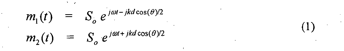
- The output E(θ,t) of a weighted addition of the two microphones can be written according to Equation (2) as follows:
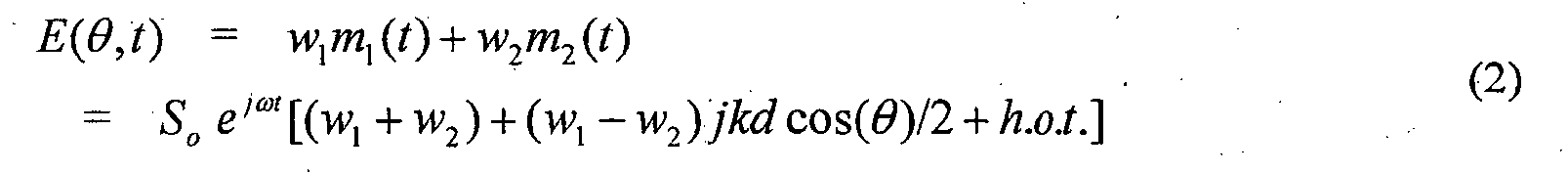
- If kd << π, then the higher-order terms ("h.o.t." in Equation (2)) can be neglected. If w 1 = -w 2, then we have the pressure difference between two closely spaced microphones. This specific case results in a dipole directivity pattern cos(θ) as can easily be seen in Equation (2). However, any first-order differential microphone pattern can be written as the sum of a zero-order (omnidirectional) term and a first-order dipole term (cos(θ)). A first-order differential microphone implies that w 1 ≈ -w 2. Thus, a first-order differential microphone has a normalized directional pattern E that can be written according to Equation (3) as follows:

Fig. 2(a) shows an example of the response for this case. In particular,Fig. 2(a) shows a directivity plot for a first-order array, where α =0.55. - When α = 0.5, the parametric algebraic equation has a specific form called a cardioid. The cardioid pattern has a zero response at θ =180°. For values of 0 ≤ α ≤ 0.5, there is a null at

Fig. 2(b) shows a directional response corresponding to α = 0.5 which is the cardioid pattern. The concentric rings in the polar plots ofFigs. 2(a) and 2(b) are 10dB apart. - A computationally simple and elegant way to form a general first-order differential microphone is to form a scalar combination of forward-facing and backward-facing cardioid signals. These signals can be obtained by using both solutions in Equation (3) and setting α = 0.5 The sum of these two cardioid signals is omnidirectional (since the cos(θ) terms subtract out), and the difference is a dipole pattern (since the constant term α subtracts out).
-
Fig. 3 shows a combination of twoomnidirectional microphones 302 to obtain back-to-back cardioid microphones. The back-to-back cardioid signals can be obtained by a simple modification of the differential combination of the omnidirectional microphones. SeeU.S. Patent No. 5,473,701 . Cardioid signals can be formed from two omnidirectional microphones by including a delay (T) before the subtraction (which is equal to the propagation time (d/c) between microphones for sounds impinging along the microphone pair axis). -
Fig. 4 shows directivity patterns for the back-to-back cardioids ofFig. 3 . The solid curve is the forward-facing cardioid, and the dashed curve is the backward-facing cardioid. - A practical way to realize the back-to-back cardioid arrangement shown in
Fig. 3 is to carefully choose the spacing between the microphones and the sampling rate of the A/D converter to be equal to some integer multiple of the required delay. By choosing the sampling rate in this way, the cardioid signals can be made simply by combining input signals that are offset by an integer number of samples. This approach removes the additional computational cost of interpolation filtering to obtain the required delay, although it is relatively simple to compute the interpolation if the sampling rate cannot be easily set to be equal to the propagation time of sound between the two sensors for on-axis propagation. - By combining the microphone signals defined in Equation (1) with the delay and subtraction as shown in
Fig. 3 , a forward-facing cardioid microphone signal can be written according to Equation (5) as follows:

- If both the forward-facing and backward-facing cardioids are averaged together, then the resulting output is given according to Equation (7) as follows:

- The subtraction of the forward-facing and backward-facing cardioids yields the dipole response of Equation (8) as follows:


-
Fig. 5 shows the frequency responses for signals incident along the microphone pair axis (θ = 0) for a dipole microphone, a cardioid-derived dipole microphone, and a cardioid-derived omnidirectional microphone. Note that the cardioid-derived dipole microphone and the cardioid-derived omnidirectional microphone have the same frequency response. In each case, the microphone-element spacing is 2 cm. At this angle, the zero occurs in the cardioid-derived dipole term at the frequency where kd = 2π. -
Fig. 6 shows the configuration of an adaptivedifferential microphone 600 as introduced in G.W. Elko and A.T. Nguyen Pong, "A simple adaptive first-order differential microphone," Proc. 1995 IEEE ASSP Workshop on Applications of Signal Proc. to Audio and Acoustics, Oct. 1995, referred to herein as "Elko-2." As represented inFig. 6 , a plane-wave signal s(t) arrives at twoomnidirectional microphones 602 at an angle θ. The microphone signals are sampled at thefrequency 1/T by analog-to-digital (A/D)converters 604 and filtered by anti-aliasing low-pass filters 606. In the following stage,delays 608 andsubtraction nodes 610 form the forward and backward cardioid signals cF (n) and cB (n) by subtracting one delayed microphone signal from the other undelayed microphone signal. As mentioned previously, one can carefully select the spacing d and thesampling rate 1/T such that the required delay for the cardioid signals is an integer multiple of the sampling rate. However, in general, one can always use an interpolation filter (not shown) to form any general required delay although this will require more computation.Multiplication node 612 andsubtraction node 614 generate the unfiltered output signal y(n) as an appropriate linear combination of cF (n) and cB (n). The adaptation factor (i.e., weight parameter) β applied atmultiplication node 612 allows a solitary null to be steered in any desired direction. With the frequency-domain signal
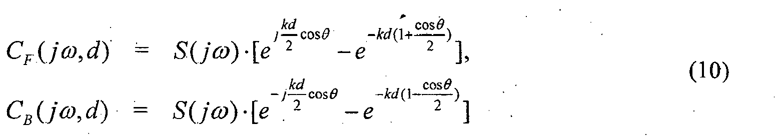

- A desired signal S(jω) arriving from straight on (θ = 0) is distorted by the factor |sin(kd)|. For a microphone used for a frequency range from about kd = 2π · 100Hz · T to kd = π/2, first-order recursive low-pass filter 616 can equalize the mentioned distortion reasonably well. There is a one-to-one relationship between the adaptation factor β and the null angle θ n as given by Equation (12) as follows:
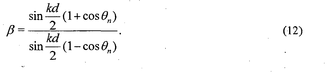
- Since it is expected that the sound field varies, it is of interest to allow the first-order microphone to adaptively compute a response that minimizes the output under a constraint that signals arriving from a selected range of direction are not impacted. An LMS or Stochastic Gradient algorithm is a commonly used adaptive algorithm due to its simplicity and ease of implementation. An LMS algorithm for the back-to-back cardioid adaptive first-order differential array is given in
U.S. Patent No. 5,473,701 and in Elko-2. -
Subtraction node 614 generates the unfiltered output signal y(n) according to Equation (13) as follows:

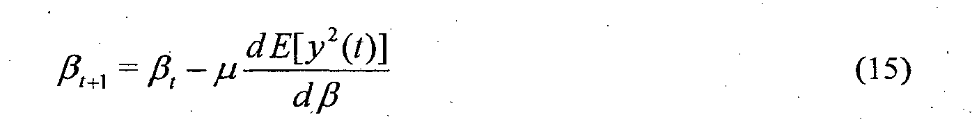
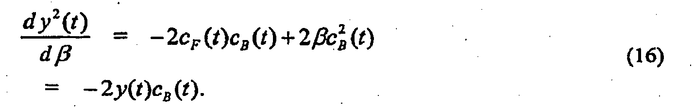

- Typically the LMS algorithm is slightly modified by normalizing the update size and adding a regularization constant ε. Normalization allows explicit convergence bounds for µ to be set that are independent of the input power. Regularization stabilizes the algorithm when the normalized input power in cB becomes too small. The LMS version with a normalized µ is therefore given by Equation (18) as follows:

- The intervals β∈[0,1] and β∈[1,∞] are mapped onto θ∈[0.5π,π] and θ∈[0,0.5π], respectively. For negative β, the directivity pattern does not contain a null. Instead, for small |β| with -1 < β < 0, a minimum occurs at θ = π ; the depth of which reduces with growing |β|. For β = -1, the pattern becomes omnidirectional and, for β < -1, the rear signals become amplified. An
adaptive algorithm 618 chooses β such that the energy of y(n) in a certain exponential or sliding window becomes a minimum. As such, β should be constrained to the interval [-1,1]. Otherwise, a null maymove into the front halfplane and suppress the desired signal. For a pure propagating acoustic field (no wind or self-noise), it can be expected that the adaptation selects a β equal to or bigger than zero. For wind and self-noise, it is expected that -1 ≤ β < 0. An observation that β would tend to values of less than 0 indicates the presence of uncorrelated signals at the two microphones. Thus, one can also use β to detect (1) wind noise and conditions where microphone self-noise dominates the input power to the microphones or (2) coherent signals that have a propagation speed much less than the speed of sound in the medium (such as coherent convected turbulence). - It should be clear that acoustic fields can be comprised of multiple simultaneous sources that vary in time and frequency. As such,
U.S. Patent No. 5,473,701 proposed that the adaptive beamformer be implemented in frequency subbands. The realization of a frequency-dependent null or minimum location is now straightforward. We replace the factor β by a filter with a frequency response H(jω) that is real and not bigger than one. The impulse response h(n) of such a filter is symmetric about the origin and hence noncausal. This involves the insertion of a proper delay d in both microphone paths. -
Fig. 7 shows a block diagram of theback end 700 of a frequency-selective first-order differential microphone. InFig. 7 , subtraction node 714, low-pass filter 716, and adaptation block 718 are analogous tosubtraction node 614, low-pass filter 616, and adaptation block 618 ofFig. 6 . Instead ofmultiplication node 612 applying adaptive weight factor β, filters 712 and 713 decompose the forward and backward cardioid signals as a linear combination of bandpass filters of a uniform filterbank. The uniform filterbank is applied to both the forward cardioid signal cF (n) and the backward cardioid signal c B (n), where m is the subband index number and Ω is the frequency. - In the embodiment of
Fig. 7 , the forward and backward cardioid signals are generated in the time domain, as shown inFig. 6 . The time-domain cardioid signals are then converted into a subband domain, e.g., using a multichannel filterbank, which implements the processing ofelements Fig. 7 by the "thick" arrow fromadaptation block 718 toelement 713. - In principle, we could directly use any standard adaptive filter algorithm (LMS, FAP, FTF, RLS ...) for the adjustment of h(n), but it would be challenging to easily incorporate the constraint H(jω)≤1. Therefore and in view of a computationally inexpensive solution, we realize H(jω) as a linear combination of band-pass filters of a uniform filterbank. The filterbank consists of M complex band-passes that are modulated versions of a low-pass filter W(jω). That filter is commonly referred to as prototype filter. See R.E. Crochiere and L.R. Rabiner, Multirate Digital Signal Processing, Prentice Hall, Englewood Cliffs, NJ, (1983), and P.P. Vaidyanathan, Multirate Systems and Filter Banks, Prentice Hall, Englewood Cliffs, NJ, (1993). Since h(n) and H(jω) have to be real, we combine band-passes with conjugate complex impulse responses. For reasons of simplicity, we choose M as a power of two so that we end up with M/2+1 channels. The coefficients β0,β1,...β K/2 control the position of the null or minimum in the different subbands. The βµ's form a linear combiner and will be adjusted by an NLMS-type algorithm.
- It is desirable to design W(jω) such that the constraint H(jω) ≤ 1 will be met automatically for all frequencies kd, given all coefficients βµ are smaller than or equal to one. The heuristic NLMS-type algorithm of the following Equations (19)-(21) is apparent:

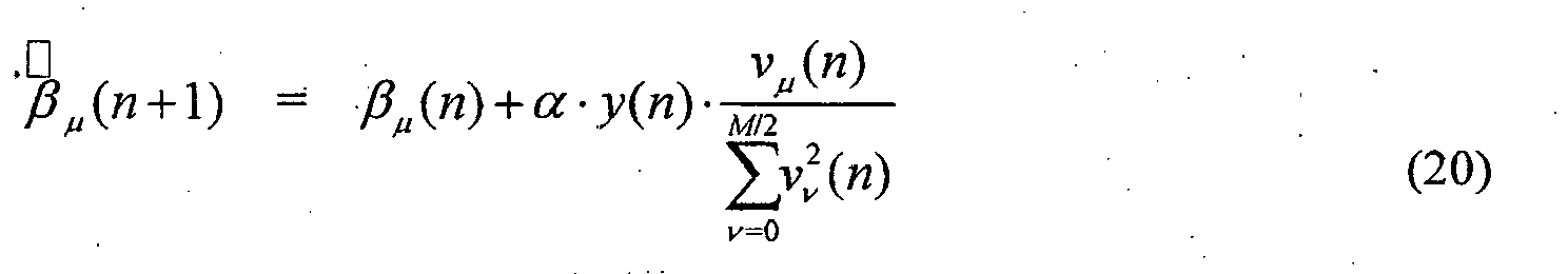
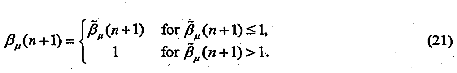
- The back-to-back cardioid power and cross-power can be related to the acoustic pressure field statistics. Using
Fig. 6 , the optimum value (in terms on the minimizing the mean-square output power) of β can be found in terms of the acoustic pressures p 1 and p 2 at the microphone inputs according to Equation (22) as follows: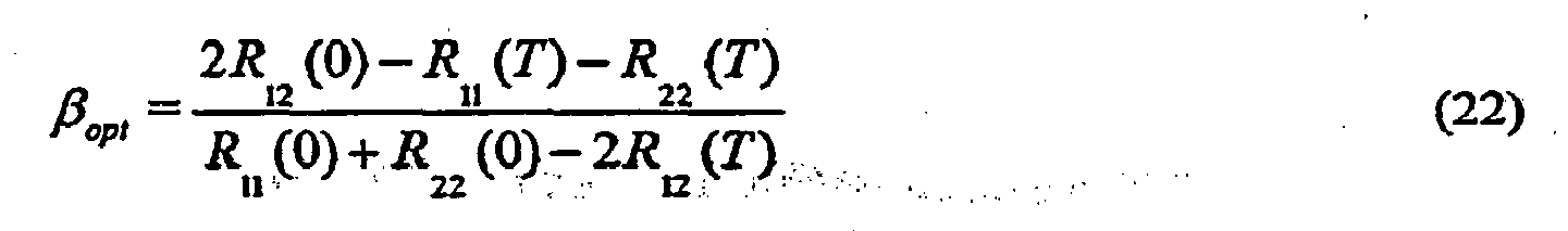
- For an isotropic noise field at frequency ω, the cross-correlation function R 12 of the acoustic pressures p 1 and p 2 at the two
sensors 102 ofFig. 1 is given by Equation (23) as follows:

- For ωT = kd, β opt is determined by substituting Equations (23) and (24) into Equation (22), yielding Equation (25) as follows:
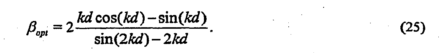
- Due to electronics, both wind noise and self-noise have approximately 1/f 2 and 1/f spectral shapes, respectively, and are uncorrelated between the two microphone channels (assuming that the microphones are spaced at a distance that is larger than the turbulence correlation length of the wind). From this assumption, Equation (22) can be reduced to Equation (26) as follows:

- It may seem redundant to include both terms in the numerator and the denominator in Equation (26), since one might expect the noise spectrum to be similar for both microphone inputs since they are so close together. However, it is quite possible that only one microphone element is exposed to the wind or turbulent jet from a talker's mouth, and, as such, it is better to keep the expression more general. A simple model for the electronics and wind-noise signals would be the output of a single-pole low-pass filter operating on a wide-sense-stationary white Gaussian signal. The low-pass filter h(t) can be written as Equation (27) as follows:

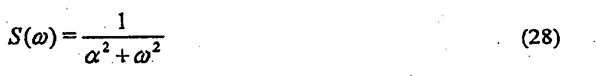

- A conservative assumption would be to assume that the low-frequency cutoff for wind and electronic noise is approximately 100 Hz. With this assumption, the time constant α is 10 milliseconds. Examining Equations (26) and (29), one can observe that, for small spacing (d on the order of 2 cm), the value of T ≈ 60 µ seconds, and thus R(T)≈1. Thus,

- Equation (30) is also valid for the case of only a single microphone exposed to the wind noise, since the power spectrum of the exposed microphone will dominate the numerator and denominator of Equation (26). Actually, this solution shows a limitation of the use of the back-to-back cardioid arrangement for this one limiting case. If only one microphone was exposed to the wind, the best solution is obvious: pick the microphone that does not have any wind contamination. A more general approach to handling asymmetric wind conditions is described in the next section.
- From the results given in Equation (30), it is apparent that, to minimize wind noise, microphone thermal noise, and circuit noise in a first-order differential array, one should allow the differential array to attain an omnidirectional pattern. At first glance, this might seem counterintuitive since an omnidirectional pattern will allow more spatial noise into the microphone output. However, if this spatial noise is wind noise, which is known to have a short correlation length, an omnidirectional pattern will result in the lowest output power as shown by Equation (30). Likewise, when there is no or very little acoustic excitation, only the uncorrelated microphone thermal and electronic noise is present, and this noise is also minimized by setting β ≈-1, as derived in Equation (30).
- As mentioned at the end of the previous section, with asymmetric wind noise, there is a solution where one can process the two microphone signals differently to attain a higher SNR output than selecting β = -1. One approach, shown in
Fig. 8 , is to linearly combine the microphone signals m 1(t) and m 2(t) to minimize the output power when wind noise is detected. The combination of the two microphone signals is constrained so that the overall sum gain of the two microphone signals is set to unity. The combined output ε(t) can be written according to Equation (31) as follows:
- Squaring the combined output ε(t) of Equation (31) to compute the combined output power ε2 yields Equation (32) as follow:

- Taking the expectation of Equation (32) yields Equation (33) as follows:

- Assuming uncorrelated inputs, where R 12(0) = 0, Equation (33) simplifies to Equation (34) as follows:

- To find the minimum, the derivative of Equation (34) is set equal to 0. Thus, the optimum value for the combining coefficient γ that minimizes the combined output ε is given by Equation (35) as follows:
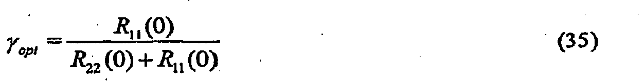
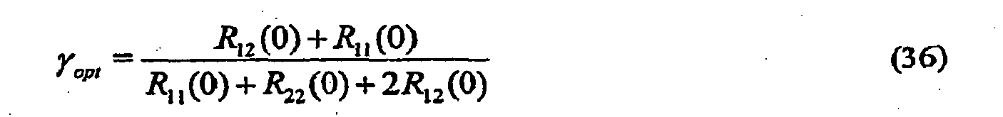


- A more-interesting case is one that covers a model of the case of a desired signal that has delay and attenuation between the microphones with independent (or less restrictively uncorrelated) additive noise. For this case, the microphone signals are given by Equation (38) as follows:
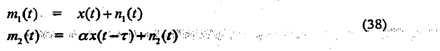
- Thus, the correlation functions can be written according to Equation (39) as follows:
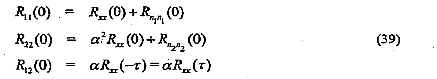
1 n1 (0) and R n2 n2 (0) are the auto-correlation functions at zero time lag for the two noise signals n 1(t) and n 2(t). - Substituting Equation (39) into Equation 36) yields Equation (40) as follows:
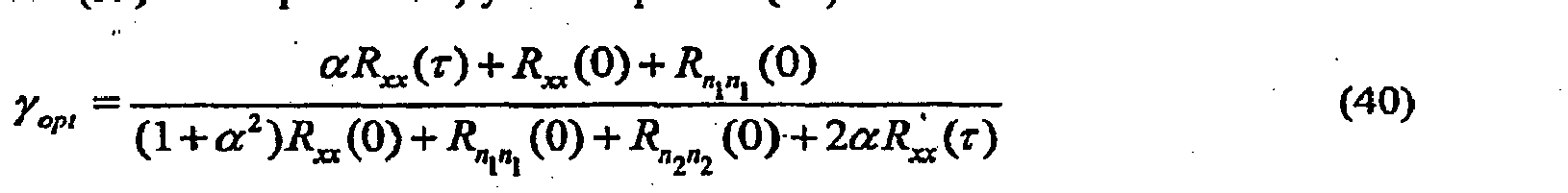
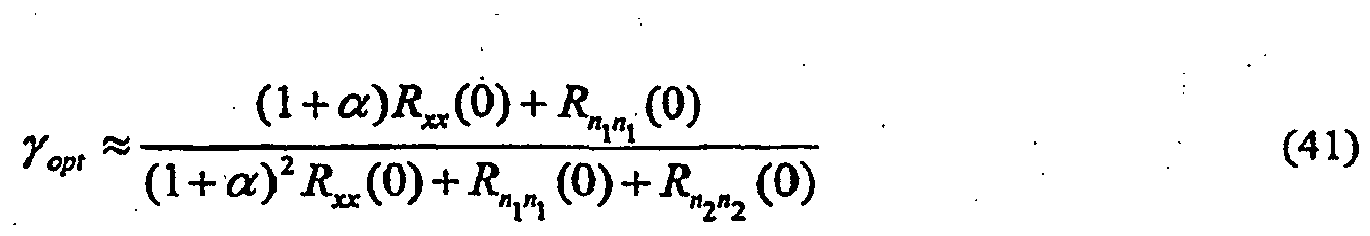
Fig. 9 shows a plot of Equation (41) for values of 0 ≤ α ≤ 1 for no noise (n 1(t) = n 2(t) = 0). As can be seen inFig. 9 , as the amplitude scale factor α goes from zero to unity, the optimum value of the combining coefficient goes from unity to one-half. - Thus, for nearfield sources with no noise, the optimum combiner will move towards the microphone with the lower power. Although this is what is desired when there is asymmetric wind noise, it is desirable to select the higher-power microphone for the wind noise-free case. In order to handle this specific case, it is desirable to form a robust wind-noise detector that is immune to the nearfield effect. This topic is covered in a later section.
- As shown in Elko-1, the sensitivity of differential microphones is proportional to k", where |k| = k = ω/c and n is the order of the differential microphone. For convective turbulence, the speed of the convected fluid perturbations is much less that the propagation speed for radiating acoustic signals. For wind noise, the difference between propagating speeds is typically by two orders of magnitude. As a result, for convective turbulence and propagating acoustic signals at the same frequency, the wave-number ratio will differ by two orders of magnitude. Since the sensitivity of differential microphones is proportional to kn , the output signal ratio of turbulent signals will be two orders of magnitude greater than the output signal ratio of propagating acoustic signals for equivalent levels of pressure fluctuation.
- A main goal of incoherent noise and turbulent wind-noise suppression is to determine what frequency components are due to noise and/or turbulence and what components are desired acoustic signals. The results of the previous sections can be combined to determine how to proceed.
-
U.S. Patent No. 7,171,008 proposes a noise-signal detection and suppression algorithm based on the ratio of the difference-signal power to the sum-signal power. If this ratio is much smaller than the maximum predicted for acoustic signals (signals propagating along the axis of the microphones), then the signal is declared noise and/or turbulent, and the signal is used to update the noise estimation. The gain that is applied can be (i) the Wiener filter gain or (ii) by a general weighting (less than 1) that (a) can be uniform across frequency or (b) can be any desired function of frequency. -
U.S. Patent No. 7,171,008 proposed to apply a suppression weighting function on the output of a two-two-microphone array based on the enforcement of the difference-to-sum power ratio. Since wind noise results in a much larger ratio, suppressing by an amount that enforces the ratio to that of pure propagating acoustic signals traveling along the axis of the microphones results in an effective solution. Expressions for the fluctuating pressure signals p 1(t) and P 2(t) at both microphones for acoustic signals traveling along the microphone axis can be written according to Equation (42) as follows: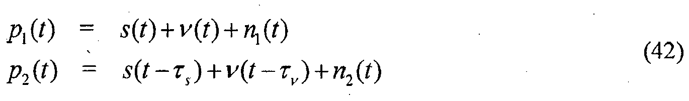
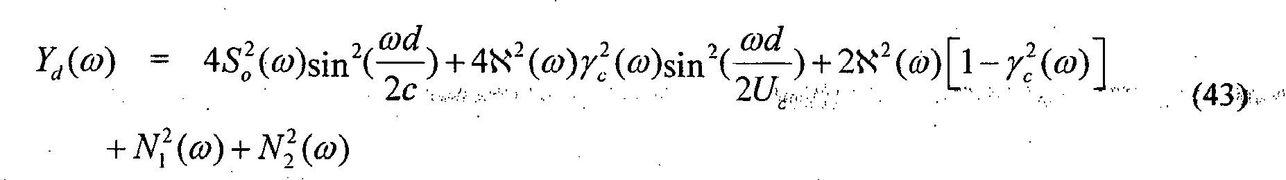
 is the RMS power of the turbulent noise, and N 1 and N 2, respectively, represent the RMS powers of the independent noise at the two microphones due to sensor self-noise.
- The ratio of these factors gives the expected power ratio R (ω) of the difference and sum signals between the microphones according to Equation (45) as follows:

- For turbulent flow where the convective wave speed is much less than the speed of sound, the power ratio R(ω) is much greater (by the ratio of the different propagation speeds). Also, since the convective-turbulence spatial-correlation function decays rapidly and this term becomes dominant when turbulence (or independent sensor self-noise is present), the resulting power ratio tends towards unity, which is even greater than the ratio difference due to the speed of propagation difference. As a reference, a purely propagating acoustic signal traveling along the microphone axis, the power ratio is given by Equation (46) as follows:

- For general orientation of a single plane-wave where the angle between the planewave and the microphone axis is θ, the power ratio is given by Equation (47) as follows:

- The results shown in Equations (46) and (47) led to a relatively simple algorithm for suppression of airflow turbulence and sensor self-noise. The rapid decay of spatial coherence results in the relative powers between the differences and sums of the closely spaced pressure (zero-order) microphones being much larger than for an acoustic planewave propagating along the microphone array axis. As a result, it is possible to detect whether the acoustic signals transduced by the microphones are turbulent-like noise or propagating acoustic signals by comparing the sum and difference powers.
Fig.10 shows the difference-to-sum power ratio for a pair of omnidirectional microphones spaced at 2 cm in a convective fluid flow propagating at 5 m/s. It is clearly seen in this figure that there is a relatively wide difference between the acoustic and turbulent sum-difference power ratios. The ratio differences become more pronounced at low frequences since the differential microphone rolls off at -6 dB/octave, where the predicted turbulent component rolls off at a much slower rate. - If sound arrives from off-axis from the microphone array, then the ratio of the difference-to-sum power levels for acoustic signals becomes even smaller as shown in Equation (47). Note that it has been assumed that the coherence decay is similar in all directions (isotropic). The power ratio R maximizes for acoustic signals propagating along the microphone axis. This limiting case is the key to the proposed wind-noise detection and suppression algorithm described in
U.S. Patent No. 7,171,008 . The proposed suppression gain G(ω) is stated as follows: If the measured ratio exceeds that given by Equation (46), then the output signal power is reduced by the difference between the measured power ratio and that predicted by Equation (46). This gain G(ω) is given by Equation (48) as follows: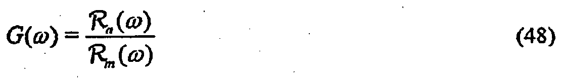
- One proposed suppression scheme is described in PCT patent application serial no.
PCT/US06/44427 . The general idea proposed in that application is to form a piecewise-linear suppression function for each subband in a frequency-domain implementation. Since there is the possibility of having a different suppression function for each subband, the suppression function can be more generally represented as a suppression matrix.Fig. 11 shows a three-segment, piecewise-linear suppression function that has been used in some implementations with good results. More segments can offer finer detail in control. Typically, the suppression values of Smin and Smax and the power ratio values Rmin and Rmax are different for each subband in a frequency-domain implementation. - Combining the suppression defined in Equation (48) with the results given on the first-order adaptive beamformer leads to a new approach to deal with wind and self-noise. A desired property of this combined system is that one can maintain directionality when wind-noise sources are smaller than acoustic signals picked up by the microphones. Another advantage of the proposed solution is that the operation of the noise suppression can be accomplished in a gradual and continuous fashion. This novel hybrid approach is expressed in Table I. In this implementation, the values of β are constrained by the value of R(ω) as determined from the electronic windscreen algorithm described in
U.S. Patent No. 7,171,008 and PCT patent application no.PCT/US06/44427 . In Table I, the directivity determined solely by the value of R(ω) is set to a fixed value. Thus, when there is no wind present, the value of β is selected by the designer to have a fixed value. As wind gradually becomes stronger, there is a monotonic mapping of the increase in R(ω) to β(ω) such that β(ω) gradually moves towards a value of -1 as the wind increases. One could also just switch the value of β to -1 when any wind is detected by the electronic windscreen or robust wind noise detectors described within this specification.Table I. Beamforming Array Operation in Conjunction with Wind-Noise Suppression by Electronic Windscreen Algorithm Acoustic Condition Electronic Windscreen Operation Directional Pattern β No wind No suppression General Cardioid 0 < β < 1 (β fixed) Slight wind Increasing suppression Subcardioid -1 < β < 0 (β is adaptive and trends to -1 as wind increases) High wind Maximum suppression Omnidirectional -1 - Similarly, one can use the constrained or unconstrained value of β(ω) to determine if there is wind noise or uncorrelated noise in the microphone channels. Table II shows appropriate settings for the directional pattern and electronic windscreen operation as a function of the constrained or unconstrained value of β(ω) from the adaptive beamformer. In Table n, the suppression function is determined solely from the value of the constrained (or even possibly unconstrained) β, where the constrained β is such that -1 < β < 1. For 0< β <1, the value of β utilized by the beamformer can be either a fixed value that the designer would choose, or allowed to be adaptive. As the value of β becomes negative, the suppression would gradually be increased until it reached the defined maximum suppression when β ≈ -1. Of course, one could use both the values of(ω) and β(ω) together to form a more-robust detection of wind and then to apply the appropriate suppression depending on how strong the wind condition is. The general scheme is that, as wind noise becomes larger and larger, the amount of suppression increases, and the value of β moves towards -1.

Table II. Wind-Noise Suppression by Electronic Windscreen Algorithm Determined by the Adaptive Beamformer Value of β Acoustic Conditions β Directional Pattern Electronic Windscreen Operation No wind 0 < β < 1 General cardioid No suppression (β fixed or adaptive) Slight wind -1 < β < 0 Subcardioid Increasing suppression High wind -1 Omnidirectional Maximum suppression - In differential microphones arrays, the magnitudes and phase responses of the microphones used to realize the arrays should match closely. The degree to which the microphones should match increases as the ratio of the microphone element spacing becomes much less than the acoustic wavelength. Thus, the mismatch in microphone gains that is inherent in inexpensive electret and condenser microphones on the market today should be controlled. This potential issue can be dealt with by calibrating the microphones during manufacture or allowing for an automatic in-situ calibration. Various methods for calibration exist and some techniques that handle automatic in-situ amplitude and phase mismatch are covered in
U.S. patent no. 7,171,008 . - One scheme that has been shown to be effective in implementation is to use an adaptive filter to match bandpass-filtered microphone envelopes.
Fig. 12 shows a block diagram of a microphoneamplitude calibration system 1200 for a set of microphones 1202. First, one microphone (microphone 1202-1 in the implementation ofFig. 12 ) is designated as the reference from which all other microphones are calibrated.Subband filterbank 1204 breaks each microphone signal into a set of subbands. The subband filterbank can be either the same as that used for the noise-suppression algorithm or some other filterbank. For speech, one can choose a band that covers the frequency range from 500 Hz to about 1 kHz. Other bands can be chosen depending on how wide the frequency averaging is desired. Multiple bands can be measured and applied to cover the case where the transducers are not flat and deviate in their relative response as a function of frequency. However, with typical condenser and electret microphones, the response is usually flat over the desired frequency band of operation. Even if the microphones are not flat in response, the microphones have similar responses if they have atmospheric pressure equalization with low-frequency rolloffs and upper resonance frequencies and Q-factors that are close to one another. - For each different subband of each different microphone signal, an envelope detector 1206 generates a measure of the subband envelope. For each non-reference microphone (each of microphones 1202-2, 1202 3, ... in the implementation of
Fig. 12 ), a single-tap adaptive filter 1208 scales the average subband envelope corresponding to one or more adjacent subbands based on a filter coefficient wj that is adaptively updated to reduce the magnitude of an error signal generated at a difference node 1210 and corresponding to the difference between the resulting filtered average subband envelope and the corresponding average reference subband envelope from envelope detector 1206-1. The resulting filter coefficient wj represents an estimate of the relative magnitude difference between the corresponding subbands of the particular non-reference microphone and the corresponding subbands of the reference microphone. One could use the microphone signals themselves rather than the subband envelopes to characterize the relative magnitude differences between the microphones, but some undesired bias can occur if one uses the actual microphone signals. However, the bias can be kept quite small if one uses a low-frequency band of a filterbank or a bandpassed signal with a low center frequency. - The time-varying filter coefficients wj for each microphone and each set of one or more adjacent subbands are applied to control
block 1212, which applies those filter coefficients to three different low-pass filters that generate three different filtered weight values: an "instantaneous" low-pass filter LPi having a high cutoff frequency (e.g., about 200 Hz) and generating an "instantaneous" filtered weight value


Fig. 12 illustrates the low-pass filtering applied bycontrol block 1212 to the filter coefficients w 2 for the second microphone.Control block 1212 applies analogous filtering to the filter coefficients corresponding to the other non-reference microphones. - As shown in
Fig. 12 ,control block 1212 also receives wind-detection signals 1214 and nearfield-detection signals 1216. Each wind-detection signal 1214 indicates whether the microphone system has detected the presence of wind in one or more microphone subbands, while each nearfield-detection signal 1216 indicates whether the microphone system has detected the presence of a nearfield acoustic source in one or more microphone subbands. In one possible implementation ofcontrol block 1212, if, for a particular microphone and for a particular subband, either the corresponding wind-detection signal 1214 indicates presence of wind or the corresponding nearfield-detection signal 1216 indicates presence of a nearfield source, then the updating of the filtered weight values for the corresponding microphone and the corresponding subband is suspended for the long-term beamformer weights, thereby maintaining those weight factors at their most-recent values until both wind and a nearfield source are no longer detected and the updating of the weight factors by the low-pass filters is resumed. A net effect of this calibration-inhibition scheme is to allow beamformer weight calibration only when farfield signals are present without wind. - The generation of wind-
detection signal 1214 by a robust wind-detection scheme based on computed wind metrics in different subbands is described in further detail below with respect toFigs. 13 and14 . Regarding generation of nearfield-detection signal 1216, nearfield source detection is based on a comparison of the output levels from the underlying back-to-back cardioid signals that are the basis signals used in the adaptive beamformer. For a headset application, where the array is pointed in the direction of the headset wearer's mouth, a nearfield source is detected by comparing the power differences between forward-facing and rearward-facing synthesized cardioid microphone patterns. Note that these cardioid microphone patterns can be realized as general forward and rearward beampatterns not necessarily having a null along the microphone axis. These beampatterns can be variable so as to minimize the headset wearer's nearfield speech in the rearward-facing synthesized beamformer. Thus, the rearward-facing beamformer may have a nearfield null, but not a null in the farfield. If the forward cardioid signal (facing the mouth) greatly exceeds the rearward cardioid signal, then a nearfield source is declared. The power differences between the forward and rearward cardioid signals can also be used to adjust the adaptive beamformer speed. Since active speech by a headset wearer can cause the adaptive beamformer to adjust to the wearer's speech, one can inhibit this undesired operation by either turning off or significantly slowing the adaptive beamformer speed of operation. In one possible implementation, the speed of operation of the adaptive beamformer can be decreased by reducing the magnitude of the update step-size µ in Equation (17). - In the last section, it was shown that, for farfield sources, the difference-to-sum power ratio is an elegant and computationally simple detector for wind and uncorrelated noise between corresponding subbands of two microphones. For nearfield operation, this simple wind-noise detector can falsely trigger even when wind is not present due to the large level differences that the microphones can have in the nearfield of the desired source. Therefore, a wind-noise detector should be robust with nearfield sources.
Figs. 13 and14 show block diagrams of wind-noise detectors that can effectively handle operation of the microphone array in the nearfield of a desired source.Figs. 13 and14 represent wind-noise detection for three adjacent subbands of two microphones: reference microphone 1202-1 and non-reference microphone 1202-2 ofFig. 12 . Analogous processing can be applied for other subbands and/or additional non-reference microphones. - As shown in
Fig. 13 , wind-noise detector 1300 comprisescontrol block 1212 ofFig. 12 , which generates instantaneous, fast, and slow weight factors


end calibration 1303. Front-end calibration 1303 represents the processing ofFig. 12 associated with the generation of filter coefficients w 2. Depending on the particular implementation,subband filterbank 1304 ofFig. 13 maybe the same as or different from subband filterbank 1204 ofFig. 12 . - For each of the three illustrated subbands of
filterbank 1304, acorresponding difference node 1308 generates the difference between the subband coefficients for reference microphone 1202-1 and weighted subband coefficients for non-reference microphone 1202-2, where the weighted subband coefficients are generated by applying the corresponding instantaneous weight factor
control block 1212 to the "raw" subband coefficients for non-reference microphone 1202-2 at acorresponding amplifier 1306. Note that, if the weight factor
amplifier 1306 will attenuate rather than amplify the raw subband coefficients. - The resulting difference values are scaled at
scalar amplifiers 1310 based on scale factors sk that depend on the spacing between the two microphones (e.g., the greater the microphone spacing and greater the frequency of the subband, the greater the scale factor). The magnitudes of the resulting scaled, subband-coefficient differences are generated atmagnitude detectors 1312. Each magnitude constitutes a measure of the difference-signal power for the corresponding subband. The three difference-signal power measures are summed atsummation block 1314, and the resulting sum is normalized atnormalization amplifier 1316 based on the summed magnitude of all three subbands for both microphones 1282-1 and 1202-2. This normalization factor constitutes a measure of the sum-signal power for all three subbands. As such, the resulting normalized value constitutes a measure of the effective difference-to-sum power ratio(described previously) for the three subbands.
- This difference-to-sum power ratiois thresholded at

threshold detector 1318 relative to a specified corresponding ratio threshold level. If the difference-to-sum power ratioexceeds the ratio threshold level, then wind is detected for those three subbands, and
control block 1212 suspends updating of the corresponding weight factors by the low-pass filters for those three subbands. -
Fig. 14 shows an alternative wind-noise detector 1400, in which a difference-to-sum power ratio Rk is estimated for each of the three different subbands atratio generators 1412, and the maximum power ratio (selected at max block 1414) is applied tothreshold detector 1418 to determine whether wind-noise is present for all three subbands. - In
Figs. 13 and14 , thescalar amplifiers - The algorithms described herein for the detection of wind noise also function effectively as algorithms for the detection of microphone thermal noise and circuit noise (where circuit noise includes quantization noise in sampled data implementations). As such, as used in this specification including the attached claims, the detection of the presence of wind noise should be interpreted as referring to the detection of the presence of any of wind noise, microphone thermal noise, and circuit noise.
-
Fig. 15 shows a block diagram of anaudio system 1500, according to the present invention.Audio system 1500 is a two-element microphone array that combines adaptive beamforming with wind-noise suppression to reduce wind noise induced into the microphone output signals. In particular,audio system 1500 comprises (i) two (e.g., omnidirectional) microphones 1502(1) and 1502(2) that generate electrical audio signals 1503(1) and 1503(2), respectively, in response to incident acoustic signals and (ii) signal-processing elements 1504-1518 that process the electrical audio signals to generate anaudio output signal 1519, where elements 1504-1514 form an adaptive beamformer, and spatial-noise suppression (SNS)processor 1518 performs wind-noise suppression as defined inU.S. patent no. 7,171,008 and in PCT patent applicationPCT/US06/44427 . -
Calibration filter 1504 calibrates bothelectrical audio signals 1503 relative to one another. This calibration can either be amplitude calibration, phase calibration, or both.U.S. patent no. 7,171,008 describes some schemes to implement this calibration in situ. In one embodiment, a first set of weight factors are applied to microphone signals 1503(1) and 1503(2) to generate first calibrated signals 1505(1) and 1505(2) for use in the adaptive beamformer, while a second set of weight factors are applied to the microphone signals to generate second calibrated signals 1520(1) and 1520(2) for use inSNS processor 1518. As describe earlier with respect toFig. 12 , the first set of weight factors are the weight factors
control block 1212, while the second set of weight factors are the weight factors
control block 1212. - Copies of the first calibrated signals 1505(1) and 1505(2) are delayed by delay blocks 1506(1) and 1506(2). In addition, first calibrated signal 1505(1) is applied to the positive input of difference node 1508(2), while first calibrated signal 1505(2) is applied to the positive input of difference node 1508(1). The delayed signals 1507(1) and 1507(2) from delay nodes 1506(1) and 1506(2) are applied to the negative inputs of difference nodes 1508(1) and 1508(2), respectively. Each difference node 1508 generates a
difference signal 1509 corresponding to the difference between the two applied signals. - Difference signals 1509 are front and back cardioid signals that are used by LMS (least mean square)
block 1510 to adaptively generatecontrol signal 1511, which corresponds to a value of adaptation factor β that minimizes the power ofoutput signal 1519.LMS block 1510 limits the value of β to a region of -1 ≤ β ≤ 0 . One modification of this procedure would be to set β to a fixed, non-zero value, when the computed value for β is greater that 0. By allowing for this case, β would be discontinuous and would therefore require some smoothing to remove any switching transient in the output audio signal. One could allow β to operate adaptively in the range -1 ≤ β ≤ 1, where operation for 0 ≤ β ≤ 1 is described inU.S. Patent No. 5,473,701 . - Difference signal 1509(1) is applied to the positive input of difference node 1514, while difference signal 1509(2) is applied to gain
element 1512, whoseoutput 1513 is applied to the negative input of difference node 1514.Gain element 1512 multiplies the rear cardioid generated by difference node 1508(2) by a scalar value computed in the LMS block to generate the adaptive beamformer output. Difference node 1514 generates a difference signal 1515 corresponding to the difference between the two applied signals 1509(1) and 1513. - After the adaptive beamformer of elements 1504-1514, first-order low-pass filter 1516 applies a low-pass filter to difference signal 1515 to compensate for the ω high-pass that is imparted by the cardioid beamformers. The resulting filtered
signal 1517 is applied to spatial-noise suppression processor 1518.SNS processor 1518 implements a generalized version of the electronic windscreen algorithm described inU.S. Patent No. 7,171,008 and PCT patent applicationPCT/US06/44427 as a subband-based processing function. Allowing the suppression to be defined generally as a piecewise linear function in the log-log domain, rather than by the ratio G(ω) given in Equation (48), allows more-precise tailoring of the desired operation of the suppression as a function of the log of the measured power ratioProcessing within
SNS block 1518 is dependent on second calibratedsignals 1520 from both microphones as well as the filteredoutput signal 1517 from the adaptive beamformer.SNS block 1518 can also use theβ control signal 1511 generated byLMS block 1510 to further refine and control the wind-noise detector and the overall suppression to the signal achieved by the SNS block. Although not shown inFig. 15 ,SNS 1518 implements equalization filtering on second calibrated signals 1520. -
Fig. 16 shows a block diagram of anaudio system 1600, according to an embodiment of the present invention.Audio system 1600 is similar toaudio system 1500 ofFig. 15 , except that, instead of receiving the calibrated microphone signals,SNS block 1618 receivessum signal 1621 anddifference signal 1623 generated by sum anddifferent nodes Sum node 1620 adds the two cardioid signals 1609(1) and 1609(2) to generatesum signal 1621, corresponding to an omnidirectional response, whiledifference node 1622 subtracts the two cardioid signals to generatedifference signal 1623, corresponding to a dipole response. The low-passfiltered sum 1617 of the two cardioid signals 1609(1) and 1613 is equal to a filtered addition of the two microphone input signals 1603(1) and 1603(2). Similarly, the low-pass filtereddifference 1623 of the two cardioid signals is equal to a filtered subtraction of the two microphone input signals. - One difference between
audio system 1500 ofFig. 15 andaudio system 1600 ofFig. 16 is thatSNS block 1518 ofFig. 15 receives the second calibrated microphone signals 1520(1) and 1520(2), whileaudio system 1600 derives sum anddifference signals audio system 1600 might not be useful with nearfield sources, one advantage toaudio system 1600 is that, since sum anddifference signals -
Fig. 17 shows a block diagram of anaudio system 1700, according to yet another embodiment of the present invention.Audio system 1700 is similar toaudio system 1500 ofFig. 15 , whereSNS block 1518 ofFig. 15 is implemented using time-domain filterbank 1724 and parametric high-pass filter 1726. Since the spectrum of wind noise is dominated by low frequencies,audio system 1700 implements filterbank 1724 as a set of time-domain band-pass filters to compute the power ratio R as a function of frequency. Havingcomputed in this fashion allows for dynamic control of parametric high-
pass filter 1726 in generating output signal 1719. In particular,filterbank 1724 generates cutoff frequency fc , which high-pass filter 1726 uses as a threshold to effectively suppress the low-frequency wind-noise components. The algorithm to compute the desired cutoff frequency uses the power ratioas well as the adaptive beamformer parameter β. When β is less than 1 but greater than 0, the cutoff frequency is set at a low value. However, as β goes negative towards the limit at -1, this indicates that there is a possibility of wind noise. Therefore, in conjunction with the power ratio a high-pass filter is progressively applied when both β goes negative and
 exceeds some defined threshold. This implementation can be less computationally demanding than a full frequency-domain algorithm, while allowing for significantly less time delay from input to output. Note that, in addition to applying low-pass filtering, block LI applies a delay to compensate for the processing time of
filterbank 1724. -
Fig. 18 shows a block diagram of anaudio system 1800, according to still another embodiment of the present invention.Audio system 1800 is analogous toaudio system 1700 ofFig. 17 , where both the adaptive beamforming and the spatial-noise suppression are implemented in the frequency domain. To achieve this frequency-domain processing,audio system 1800 has M-tap FFT-basedsubband filterbank 1824, which converts each time-domain audio signal 1803 into (1+M/2) frequency-domain signals 1825. Moving the subband filter decomposition to the output of the microphone calibration results in multiple, simultaneous, adaptive, first-order beamformers, whereSNS block 1818 implements processing analogous to that ofSNS 1518 ofFig. 15 for eachdifferent beamformer output 1815 based on a corresponding frequency-dependent adaptation parameter β represented by frequencydependent control signal 1811. Note that, in this frequency-domain implementation, there is no low-pass filter implemented betweendifference node 1814 andSNS block 1818. - One advantage of this implementation over the time-domain adaptive beamformers of
Figs. 15-17 is that multiple noise sources arriving from different directions at different frequencies can now be simultaneously minimized. Also, since wind noise and electronic noise have a 1/f or even 1/f 2 dependence, a subband implementation allows the microphone to tend towards omnidirectional at the dominant low frequencies when wind is present, and remain directional at higher frequencies where the interfering noise source might be dominated by acoustic noise signals. As with the modification shown inFig. 16 , processing of the sum and difference signals can alternatively be accomplished in the frequency domain by directly using the two back-to-back cardioid signals. - The previous descriptions have been limited to first-order differential arrays. However, the processing schemes to reduce wind and circuit noise for first-order arrays are similarly applicable to higher-order differential arrays, which schemes are developed here.
- For a plane-wave signal s(t) with spectrum S(ω) and wavevector k incident on a three-element array with displacement vector d shown in
Fig. 19 , the output can be written as:
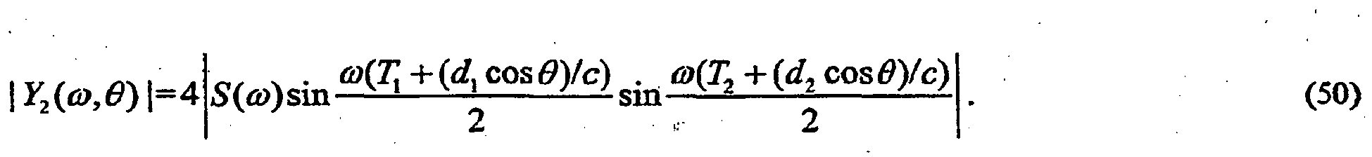
- Now, it is assumed that the spacing and delay are small such that kd1, kd2 <<π and ωT1, ωT2 <<π, so that:
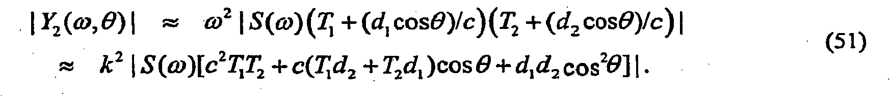
- The terms inside the brackets in Equation (51) contain the array directional response, composed of a monopole term, a first-order dipole term cosθ that resolves the component of the acoustic particle velocity along the sensor axis, and a linear quadruple term cos2θ. One thing to notice in Equation (51) is that the second-order array has a second-order differentiator frequency dependence (i.e., output increases quadratically with frequency). This frequency dependence is compensated in practice by a second-order lowpass filter.
- The topology shown in
Fig. 19 can be extended to any order as long as the total length of the array is much smaller than the acoustic wavelength of the incoming desired signals. With the small spacing approximation, the response of an Nth -order differential sensor (N + 1 sensors) to incoming plane waves is: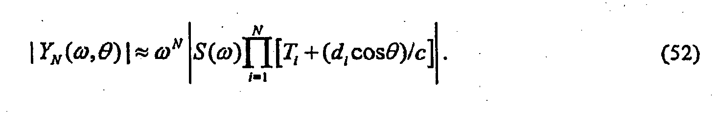
- In the design of differential arrays, the array directivity is of major interest. One possible way to simplify the analysis for the directivity of the Nth -order array is to define a variable α i such that:
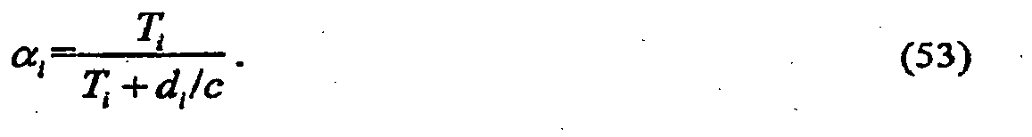
- The array response can then be rewritten as:
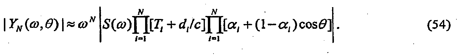
- The last product term expresses the angular dependence of the array, the terms that precede it determine the sensitivity of the array as a function of frequency, spacing, and time delay. The last product term contains the angular dependence of the array. Now define an output lowpass filter HL (ω) as:

- This definition for HL (ω) results in a flat frequency response and unity gain for signals arriving from θ = 0°. Note that this is true for frequencies and spacings where the small kd approximation is valid The exact response can be calculated from Equation (50). With the filter described in Equation (55), the output signal is:
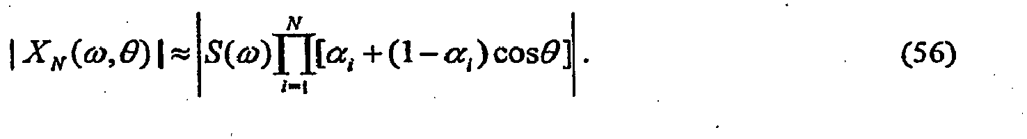
- Thus, the directionality of an Nth -order differential array is the product of N first-order directional responses, which is a restatement of the pattern multiplication theorem in electroacoustics. If the α i are constrained as 0 ≤ α i ≤ 0.5, then the directional response of the Nth -order array shown in Equation (54) contains N zeros (or nulls) at angles between 90° ≤ θ ≤ 180°. The null locations can be calculated for the α i as:

- One possible realization of the second-order adaptive differential array variable time delays T 1 and T 2 is shown in
Fig. 19 . This solution generates any time delay less than or equal to di /c. The computational requirements needed to realize the general delay by interpolation filtering and the resulting adaptive algorithms may be unattractive for an extremely low complexity real-time implementation. Another way to efficiently implement the adaptive differential array is to use an extension of the back-to-back cardioid configuration using a sampling rate whose sampling period is an integer multiple or divisor of the time delay for on-axis acoustic waves to propagate between the microphones, as described earlier. -
Fig. 20 shows a schematic implementation of an adaptive second-order array differential microphone utilizing fixed delays and three omnidirectional microphone elements. The back-to-back cardioid arrangement for a second-order array can be implemented as shown inFig. 20 . This topology can be followed to extend the differential array to any desired order. One simplification utilized here is the assumption that the distance d 1 between microphones m1 and m2 is equal to the distance d 2 between microphones m2 and m3, although this is not necessary to realize the second-order differential array. This simplification does not limit the design but simplifies the design and analysis. There are some other benefits to the implementation that result by assuming that all di are equal. One major benefit is the need for only one unique delay element. For digital signal processing, this delay can be realized as one sampling period, but, since fractional delays are relatively easy to implement, this advantage is not that significant. Furthermore, by setting the sampling period equal to d/c, the back-to-back cardioid microphone outputs can be formed directly. Thus, if one chooses the spacing and the sampling rates appropriately, the desired second-order directional response of the array can be formed by storing only a few sequential sample values from each channel. As previously discussed, the lowpass filter shown following the output y(t) inFig. 20 is used to compensate the second-order ω2 differentiator response. - The null angles for the Nth -order array are at the null locations of each first-order section that constitutes the canonic form. The null location for each section is:
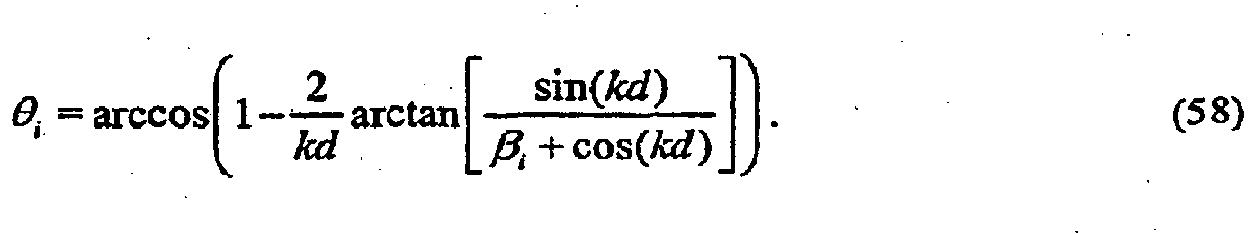
- Note that, for βi = 1, θi = 90° ; and, for βi = 0, θi =180°. For small kd (kd = ωT <<π):

- The relationship between β i and the α i defmed in Equation (53) is:

- The optimum values of β i are defined here as the values of β i that minimize the mean-square output from the sensor. Starting with a topology that is a straightforward extension to the first-order adaptive differential array developed earlier and shown in
Fig. 20 , the equations describing the input/output relationship y(t) for the second-order array can be written as: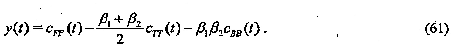
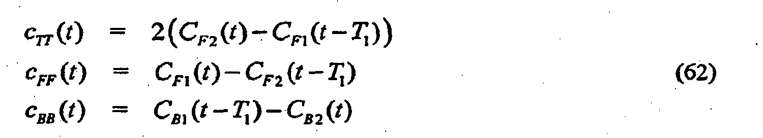

- The terms C F1(t) and C F2(t) are the two signals for the forward facing cardioid outputs formed as shown in
Fig. 20 . Similarly, C B1(t) and C B2(t) are the corresponding backward facing cardioid signals. The scaling of cTT by a scalar factor of will become clear later on in the derivations. A further simplification can be made to Equation (61) yielding:
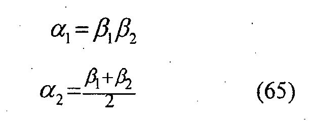
- These results have an appealing intuitive form if one looks at the beam-patterns associated with the signals cFF (t), CBB (t), and cTT (t). These directivity functions are phase aligned relative to the center microphone, i.e., they are all real when the coordinate origin is located at the center of the array
Fig. 21 shows the associated directivity patterns of signals cFF (t), cBB (t), and cTT (t) as described in Equations (62).. Note that the second-order dipole plot (cTT) is representative of a toroidal pattern (one should think of the pattern as that made by rotating this figure around a line on the page that is along the null axis). From this figure, it can be seen that the second-order adaptive scheme presented here is actually an implementation of a Multiple Sidelobe Canceler (MSLC). See R.A. Monzingo and T.W. Miller, Introduction to Adaptive Arrays, Wiley, New York, (1980). The intuitive way to understand the proposed grouping of the terms given in Equation (64) is to note that the beam associated with signal cFF is aimed in the desired source direction. The beams represented by the signals cBB and cTT are then used to place nulls at specific directions by subtracting their output from cFF. - The locations of the nulls in the pattern can be found as follows:
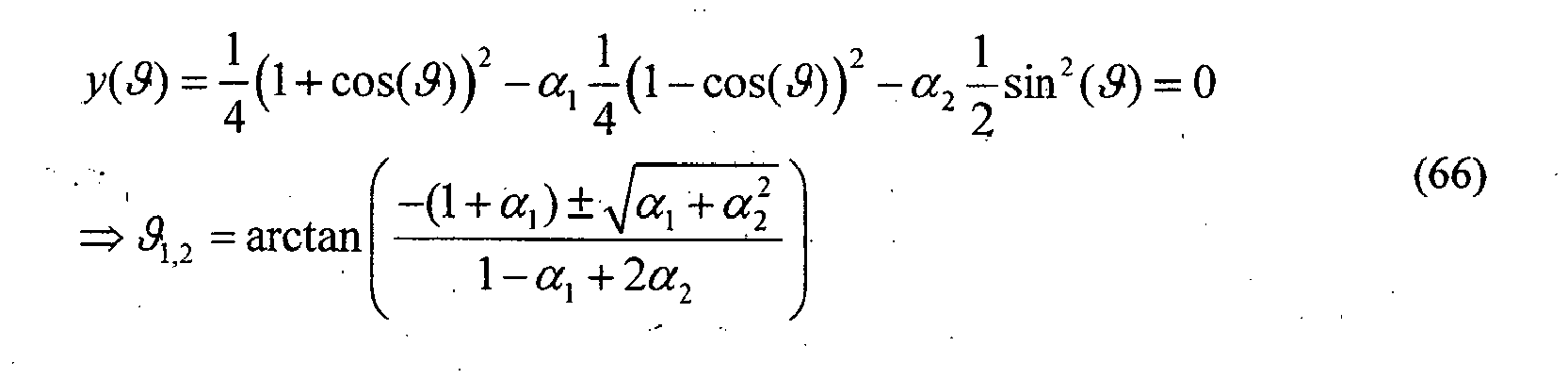
- To find the optimum α1,2 values, start with squaring Equation (64):

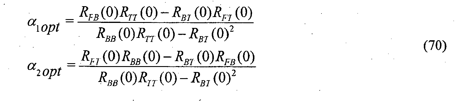
- To simplify the computation of R, the base pattern is written in terms of spherical harmonics. The spherical harmonics possess the desirable property that they are mutually orthonormal, where:
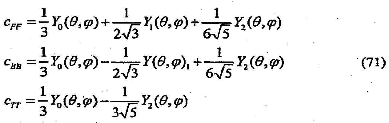
- Based on these expressions, the values for the auto-and cross-correlations are:
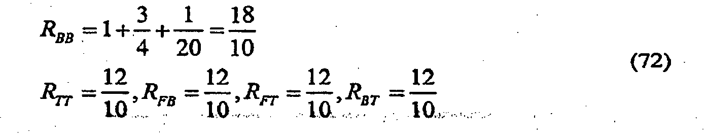
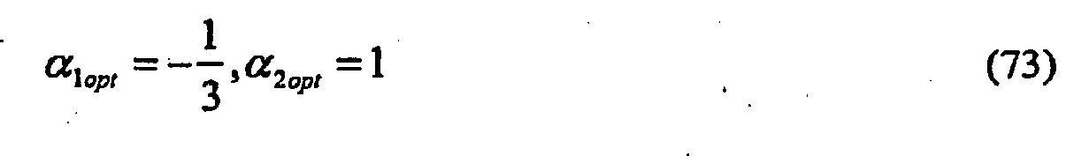
- It can be verified that these settings for α result in the second hypercardioid pattern which is known to maximize the directivity index (DI).
- In
Fig. 20 , microphones m1, m2, and m3 are positioned in a one-dimensional (i.e., linear) array, and cardioid signals C F1, C B1, C F2, and C B2 are first-order cardioid signals. Note that the output ofdifference node 2002 is a first-order audio signal analogous to signal y(n) ofFig. 6 , where the first and second microphone signals ofFig. 20 correspond to the two microphone signals ofFig. 6 . Note further that the output ofdifference node 2004 is also a first-order audio signal analogous to signal y(n) ofFig. 6 , as generated based on the second and third microphone signals ofFig. 20 , rather than on the first and second microphone signals. - Moreover, the outputs of
difference nodes Fig. 20 is a second-order audio signal corresponding to a second-order beampattern. For certain values of adaptation factors β1 and β2 (e.g., both negative), the second-order beampattern ofFig. 20 will have no nulls. - Although
Fig. 20 shows the same adaptation factor β1 applied to both the first backward cardioid signal C B1 and the second backward cardioid signal C B2, in theory, two different adaptation factors could be applied to those signals. Similarly, althoughFig. 20 shows the same delay value T 1 being applied by all five delay elements, in theory, up to five different delay values could be applied by those delay elements. - The LMS or Stochastic Gradient algorithm is a commonly used adaptive algorithm due to its simplicity and ease of implementation. The LMS algorithm is developed in this section for the second-order adaptive differential array. To begin, recall:

- The steepest descent algorithm finds a minimum of the error surface E[y2 (t)] by stepping in the direction opposite to the gradient of the surface with respect to the weight parameters α1 and α2. The steepest descent update equation can be written as:


- Thus the LMS update equation is:

- Typically, the LMS algorithm is slightly modified by normalizing the update size so that explicit convergence bounds for µ i can be stated that are independent of the input power. The LMS version with a normalized µ i (NLMS) is therefore:
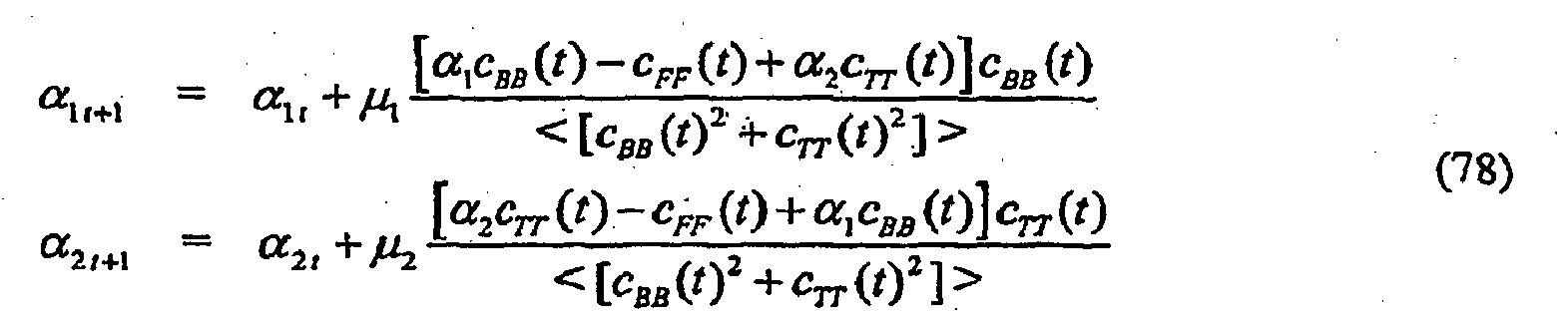
- A more compact derivation for the update equations can be obtained by defining the following definitions:


- Since the look direction is known, the adaptation of the array is constrained such that the two independent nulls do not fall in spatial directions that would result in an attenuation of the desired direction relative, to all other directions. In practice, this is accomplished by constraining the values for α1,2. An intuitive constraint would be to limit the coefficients so that the resulting zeros cannot be in the front half plane. This constraint is can be applied on β1,2; however, it turns out that it is more involved in strictly applying this constraint on α1,2. Another possible constraint would be to limit the coefficients so that the sensitivity to any direction cannot exceed the sensitivity for the look direction. This constraint results in the following limits:

-
Fig. 22 schematically shows how to combine the second-order adaptive microphone along with a multichannel spatial noise suppression (SNS) algorithm. This is an extension of the first-order adaptive beamformer as described earlier. By following this canonic representation of higher-order differential arrays into cascaded first-order sections, this combined constrained adaptive beamformer and spatial noise suppression architecture can be extended to orders higher than two. - The audio systems of
Figs. 15-18 combine a constrained adaptive first-order differential microphone array with dual-channel wind-noise suppression and spatial noise suppression. The flexible result allows a two-element microphone array to attain directionality as a function of frequency, when wind is absent to minimize undesired acoustic background noise and then to gradually modify the array's operation as wind noise increases. Adding information of the adaptive beamformer coefficient β to the input of the parametric dual-channel suppression operation can improve the detection of wind noise and electronic noise in the microphone output. This additional information can be used to modify the noise suppression function to effect a smooth transition from directional to omnidirectional and then to increase suppression as the noise power increases. In the audio system ofFig. 18 , the adaptive beamformer operates in the subband domain of the suppression function, thereby advantageously allowing the beampattern to vary over frequency. The ability of the adaptive microphone to automatically operate to minimize sources of undesired spatial, electronic, and wind noise as a function of frequency should be highly desirable in hand-held mobile communication devices. - Although the present invention has been described in the context of an audio system in which the adaptation factor is applied to the backward cardioid signal, as in
Fig. 6 , the present invention can also be implemented in the context of audio systems in which an adaptation factor is applied to the forward cardioid signal, either instead of or in addition to an adaptation factor being applied to the backward cardioid signal. - Although the present invention has been described in the context of systems having two microphones, the present invention can also be implemented using more than two microphones. Note that, in general, the microphones may be arranged in any suitable one-, two-, or even three-dimensional configuration. For instance, the processing could be done with multiple pairs of microphones that are closely spaced and the overall weighting could be a weighted and summed version of the pair-weights as computed in Equation (48). In addition, the multiple coherence function (reference: Bendat and Piersol, "Engineering applications of correlation and spectral analysis", Wiley Interscience, 1993.) could be used to determine the amount of suppression for more than two inputs. The use of the difference-to-sum power ratio can also be extended to higher-order differences. Such a scheme would involve computing higher-order differences between multiple microphone signals and comparing them to lower-order differences and zero-order differences (sums). In general, the maximum order is one less than the total number of microphones, where the microphones are preferably relatively closely spaced.
- As used in the claims, the term "power" in intended to cover conventional power metrics as well as other measures of signal level, such as, but not limited to, amplitude and average magnitude. Since power estimation involves some form of time or ensemble averaging, it is clear that one could use different time constants and averaging techniques to smooth the power estimate such as asymmetric fast-attack, slow-decay types of estimators. Aside from averaging the power in various ways, one can also average the ratio of difference and sum signal powers by various time-smoothing techniques to form a smoothed estimate of the ratio.
- As used in the claims, the term first-order "cardioid" refers generally to any directional pattern that can be represented as a sum of omnidirectional and dipole components as described in Equation (3). Higher-order cardioids can likewise be represented as multiplicative beamformers as described in Equation (56). The term "forward cardioid signal' corresponds to a beampattern having its main lobe facing forward with a null at least 90 degrees away, while the term "backward cardioid signal" corresponds to a beampattern having its main lobe facing backward with a null at least 90 degrees away.
- In a system having more than two microphones, audio signals from a subset of the microphones (e.g., the two microphones having greatest power) could be selected for filtering to compensate for wind noise. This would allow the system to continue to operate even in the event of a complete failure of one (or possibly more) of the microphones.
- The present invention can be implemented for a wide variety of applications having noise in audio signals, including, but certainly not limited to, consumer devices such as laptop computers, hearing aids, cell phones, and consumer recording devices such as camcorders. Notwithstanding their relatively small size, individual hearing aids can now be manufactured with two or more sensors and sufficient digital processing power to significantly reduce diffuse spatial noise using the present invention.
- Although the present invention has been describe in the context of air applications, the present invention can also be applied in other applications, such as underwater applications. The invention can also be useful for removing bending wave vibrations in structures below the coincidence frequency where the propagating wave speed becomes less than the speed of sound in the surrounding air or fluid.
- Although the calibration processing of the present invention has been described in the context of audio systems, those skilled in the art will understand that this calibration estimation and correction can be applied to other audio systems in which it is required or even just desirable to use two or more microphones that are matched in amplitude and/or phase.
- The present invention may be implemented as analog or digital circuit-based processes, including possible implementation on a single integrated circuit. As would be apparent to one skilled in the art, various functions of circuit elements may also be implemented as processing steps in a software program. Such software may be employed in, for example, a digital signal processor, micro-controller, or general-purpose computer.
- The present invention can be implemented in the form of methods and apparatuses for practicing those methods. The present invention can also be implemented in the form of program code embodied in tangible media, such as floppy diskettes, CD-ROMs, hard drives, or any other machine-readable storage medium, wherein, when the program code is loaded into and executed by a machine, such as a computer, the machine becomes an apparatus for practicing the invention. The present invention can also be implemented in the form of program code, for example, whether stored in a storage medium, loaded into and/or executed by a machine, or transmitted over some transmission medium or carrier, such as over electrical wiring or cabling, through fiber optics, or via electromagnetic radiation, wherein, when the program code is loaded into and executed by a machine, such as a computer, the machine becomes an apparatus for practicing the invention. When implemented on a general-purpose processor, the program code segments combine with the processor to provide a unique device that operates analogously to specific logic circuits.
- Unless explicitly stated otherwise, each numerical value and range should be interpreted as being approximate as if the word "about" or "approximately" preceded the value of the value or range.
- Reference herein to "one embodiment" or "an embodiment" means that a particular feature, structure, or characteristic described in connection with the embodiment can be included in at least one embodiment of the invention. The appearances of the phrase "in one embodiment" in various places in the specification are not necessarily all referring to the same embodiment, nor are separate or alternative embodiments necessarily mutually exclusive of other embodiments. The same applies to the term "implementation."
- The use of figure numbers and/or figure reference labels in the claims is intended to identify one or more possible embodiments of the claimed subject matter in order to facilitate the interpretation of the claims. Such use is not to be construed as necessarily limiting the scope of those claims to the embodiments shown in the corresponding figures.
- It will be further understood that various changes in the details, materials, and arrangements of the parts which have been described and illustrated in order to explain the nature of this invention may be made by those skilled in the art without departing from the principle and scope of the invention as expressed in the following claims. Although the steps in the following method claims, if any, are recited in a particular sequence with corresponding labeling, unless the claim recitations otherwise imply a particular sequence for implementing some or all of those steps; those steps are not necessarily intended to be limited to being implemented in that particular sequence.
Claims (15)
- A method for processing audio signals, comprising:(a) generating first and second cardioid signals (1509(1) and 1509(2)) from first and second microphone signals (1503(1) and 1503(2)) to obtain back-to-back facing cardiod signals of first and second omnidirectional microphones based on a microphone signal delay equal to the propagation time between the first and second omnidirectional microphones for sounds impinging along a microphone pair axis of the first and second omnidirectional microphones;(b) determining that one or more of wind noise, thermal noise, and circuit noise are present in the first and second microphone signals;(c) generating a first adaptation factor (1511), wherein:the first adaptation factor is constrained to a range of values being greater than or equal to -1 and less than 0, such that the first adaptation factor gradually moves towards a value of -1 as the noise increases;(d) applying the first adaptation factor by multiplying it with the second cardioid signal to generate an adapted second cardioid signal (1513); and(e) combining the first cardioid signal and the adapted second cardioid signal to generate a first output audio signal (1515), wherein the first output audio signal corresponds to a first beampattern having no nulls.
- The method of claim 1, wherein:the first cardioid signal is a forward cardioid signal;the second cardioid signal is a backward cardioid signal; andthe adapted backward cardioid signal is subtracted from the forward cardioid signal to generate the first output audio signal.
- The method of any of claims 1-2, wherein the first adaptation factor is generated based on the second cardioid signal and the first output audio signal.
- The method of claim 3, further comprising the steps of:determining whether a nearfield source is present by comparing output levels from the first and second cardioid signals; anddecreasing an update step-size used in generating adjustments for the first adaptation factor to reduce adaptation speed for generating the first output audio signal, if the nearfield source is determined to be present.
- The method of any of claims 1-4, wherein:steps (b), (c), (d), and (e) are implemented in a subband domain such that the first adaptation factor for a first subband is constrained to the first range of values while the first adaptation factor for a second subband is concurrently constrained to the range of values.
- The method of any of claims 1-5, further comprising:(f) applying noise suppression processing to the first output audio signal to generate a noise-suppressed output audio signal, wherein the noise suppression processing is controlled based on the first adaptation factor and step (f) comprises:(1) generating a difference-signal power based on the first and second microphone signals;(2) generating a sum-signal power based on first and second microphone signals;(3) generating a power ratio based on the difference-signal power and the sum-signal power;(4) generating a suppression value based on the power ratio; and(5) applying the noise suppression processing to the first output audio signal based on the suppression value to generate the noise-suppressed output audio signal.
- The method of claim 6, wherein:the suppression processing is based on both the power ratio and the first adaptation factor; andstep (c) comprises generating the first adaptation factor based on the power ratio.
- The method of claim 7, wherein:step (f) is implemented in the subband domain to generate a suppression level for each subband;
andsteps (b), (c), (d), and (e) are implemented in the subband domain such that the first adaptation factor for a first subband in which wind noise is absent is constrained to the first range of values while the first adaptation factor for a second subband in which wind noise is present is concurrently constrained to the range of values. - The method of claim 1, wherein step (a) comprises filtering at least one of the first and second microphone signals based on a first weight factor prior to generating the first and second cardioid signals.
- The method of claim 9, wherein the first weight factor is generated by:(1) selecting one microphone signal as a reference signal and another microphone signal as a calibrated signal;(2) determining an envelope level for each of the first and second microphone signals;(3) applying a calibration weight factor to the envelope level of the calibrated signal to generate an adjusted calibration-signal envelope level;(4) updating the calibration weight factor to decrease a difference between the envelope level of the reference signal and the adjusted calibration-signal envelope level; and(5) applying the updated calibration weight factor to a first low-pass filter to generate the first weight factor for the filtering of step (a).
- The method of claim 10, further comprising:(6) determining whether a nearfield source is present, wherein updating of the first weight factor based on the updated calibration weight factor is suspended if any of the wind noise, the thermal noise, and the circuit noise are determined to be present or if the nearfield source is determined to be present.
- The method of claim 1, wherein:the first output audio signal is a first-order signal; andfurther comprising:(f) generating third and fourth cardioid signals (C F2 and C B2 of Fig. 20) from one of the first and second microphone signals (p 2) and a third microphone signal (p 3);(g) generating a second adaptation factor (β1);(h) applying the second adaptation factor to the fourth cardioid signal to generate an adapted fourth cardioid signal;(i) combining the third cardioid signal and the adapted fourth cardioid signal to generate a second, first-order output audio signal corresponding to a second beampattern having no nulls for at least one value of the second adaptation factor; and(j) combining the first output audio signal and the second output audio signal to form a second-order output audio signal corresponding to a third beampattern having no nulls for at least one value of the first adaptation factor and at least one value of the second adaptation factor.
- The method of claim 12, wherein step (j) comprises:(1) generating first and second second-order cardioid signals from the first and second first-order output audio signals;(2) generating a third adaptation factor (β2);(3) applying the third adaptation factor to the first second-order cardioid signal to generate an adapted first second-order cardioid signal;(4) combining the second second-order cardioid signal and the adapted first second-order cardioid signal to generate the second-order output audio signal.
- The method of claim 1, wherein:if the wind noise, the thermal noise, and the circuit noise are determined not to be present, then the first adaptation factor is set equal to a specified value in the first range of values; andif any of the wind noise, the thermal noise, and the circuit noise are determined to be present, then the first adaptation factor is adaptively generated based on the second cardioid signal and the first output audio signal to be in the range of values.
- An audio system for processing audio signals, comprising:(a) means for generating first and second cardioid signals to obtain back-to-back facing cardiod signals from first and second microphone signals of first and second omnidirectional microphones based on a microphone signal delay equal to the propagation time between the first and second omnidirectional microphones for sounds impinging along a microphone pair axis of the first and second omnidirectional microphones;(b) means for determining that one or more of wind noise, thermal noise, and circuit noise are present in the first and second microphone signals;(c) an adaptation block adapted to generate a first adaptation factor, wherein:the first adaptation factor is constrained to a range of values being greater than or equal to -1 and less than 0, such that the first adaptation factor gradually moves towards a value of -1 as the noise increases;(d) a multiplication node adapted to apply the first adaptation factor by multiplying it with the second cardioid signal to generate an adapted second cardioid signal; and(e) a combiner adapted to combine the first cardioid signal and the adapted second cardioid signal to generate a first output audio signal, wherein the first output audio signal corresponds to a first beampattern having no nulls.
Applications Claiming Priority (2)
| Application Number | Priority Date | Filing Date | Title |
|---|---|---|---|
| US78125006P | 2006-03-10 | 2006-03-10 | |
| PCT/US2007/006093 WO2007106399A2 (en) | 2006-03-10 | 2007-03-09 | Noise-reducing directional microphone array |
Publications (2)
| Publication Number | Publication Date |
|---|---|
| EP1994788A2 EP1994788A2 (en) | 2008-11-26 |
| EP1994788B1 true EP1994788B1 (en) | 2014-05-07 |
Family
ID=38326291
Family Applications (1)
| Application Number | Title | Priority Date | Filing Date |
|---|---|---|---|
| EP07752770.3A Active EP1994788B1 (en) | 2006-03-10 | 2007-03-09 | Noise-reducing directional microphone array |
Country Status (3)
| Country | Link |
|---|---|
| US (3) | US8942387B2 (en) |
| EP (1) | EP1994788B1 (en) |
| WO (1) | WO2007106399A2 (en) |
Families Citing this family (221)
| Publication number | Priority date | Publication date | Assignee | Title |
|---|---|---|---|---|
| US8280072B2 (en) | 2003-03-27 | 2012-10-02 | Aliphcom, Inc. | Microphone array with rear venting |
| US8503691B2 (en) * | 2007-06-13 | 2013-08-06 | Aliphcom | Virtual microphone arrays using dual omnidirectional microphone array (DOMA) |
| US8019091B2 (en) | 2000-07-19 | 2011-09-13 | Aliphcom, Inc. | Voice activity detector (VAD) -based multiple-microphone acoustic noise suppression |
| US8452023B2 (en) * | 2007-05-25 | 2013-05-28 | Aliphcom | Wind suppression/replacement component for use with electronic systems |
| US8098844B2 (en) * | 2002-02-05 | 2012-01-17 | Mh Acoustics, Llc | Dual-microphone spatial noise suppression |
| US9066186B2 (en) | 2003-01-30 | 2015-06-23 | Aliphcom | Light-based detection for acoustic applications |
| US9099094B2 (en) | 2003-03-27 | 2015-08-04 | Aliphcom | Microphone array with rear venting |
| EP1994788B1 (en) | 2006-03-10 | 2014-05-07 | MH Acoustics, LLC | Noise-reducing directional microphone array |
| US20070244698A1 (en) * | 2006-04-18 | 2007-10-18 | Dugger Jeffery D | Response-select null steering circuit |
| JP2008263498A (en) * | 2007-04-13 | 2008-10-30 | Sanyo Electric Co Ltd | Wind noise reducing device, sound signal recorder and imaging apparatus |
| US11217237B2 (en) * | 2008-04-14 | 2022-01-04 | Staton Techiya, Llc | Method and device for voice operated control |
| CN102177732B (en) * | 2007-08-22 | 2013-11-13 | 松下电器产业株式会社 | Directional microphone device |
| US8046219B2 (en) | 2007-10-18 | 2011-10-25 | Motorola Mobility, Inc. | Robust two microphone noise suppression system |
| ATE554481T1 (en) * | 2007-11-21 | 2012-05-15 | Nuance Communications Inc | TALKER LOCALIZATION |
| WO2009069184A1 (en) * | 2007-11-26 | 2009-06-04 | Fujitsu Limited | Sound processing device, correcting device, correcting method and computer program |
| JP5097523B2 (en) * | 2007-12-07 | 2012-12-12 | 船井電機株式会社 | Voice input device |
| JP5257366B2 (en) * | 2007-12-19 | 2013-08-07 | 富士通株式会社 | Noise suppression device, noise suppression control device, noise suppression method, and noise suppression program |
| EP2238592B1 (en) | 2008-02-05 | 2012-03-28 | Phonak AG | Method for reducing noise in an input signal of a hearing device as well as a hearing device |
| US8340333B2 (en) * | 2008-02-29 | 2012-12-25 | Sonic Innovations, Inc. | Hearing aid noise reduction method, system, and apparatus |
| EP2107826A1 (en) * | 2008-03-31 | 2009-10-07 | Bernafon AG | A directional hearing aid system |
| US9202475B2 (en) * | 2008-09-02 | 2015-12-01 | Mh Acoustics Llc | Noise-reducing directional microphone ARRAYOCO |
| WO2010044002A2 (en) * | 2008-10-16 | 2010-04-22 | Nxp B.V. | Microphone system and method of operating the same |
| US8249862B1 (en) * | 2009-04-15 | 2012-08-21 | Mediatek Inc. | Audio processing apparatuses |
| FR2945696B1 (en) * | 2009-05-14 | 2012-02-24 | Parrot | METHOD FOR SELECTING A MICROPHONE AMONG TWO OR MORE MICROPHONES, FOR A SPEECH PROCESSING SYSTEM SUCH AS A "HANDS-FREE" TELEPHONE DEVICE OPERATING IN A NOISE ENVIRONMENT. |
| US8515109B2 (en) * | 2009-11-19 | 2013-08-20 | Gn Resound A/S | Hearing aid with beamforming capability |
| EP2339574B1 (en) * | 2009-11-20 | 2013-03-13 | Nxp B.V. | Speech detector |
| DE112010004682T5 (en) * | 2009-12-04 | 2013-03-28 | Masimo Corporation | Calibration for multi-level physiological monitors |
| JP2011147103A (en) | 2009-12-15 | 2011-07-28 | Canon Inc | Audio signal processing device |
| WO2011107545A2 (en) * | 2010-03-05 | 2011-09-09 | Siemens Medical Instruments Pte. Ltd. | Method for adjusting a directional hearing device |
| TWI459828B (en) * | 2010-03-08 | 2014-11-01 | Dolby Lab Licensing Corp | Method and system for scaling ducking of speech-relevant channels in multi-channel audio |
| US8538035B2 (en) | 2010-04-29 | 2013-09-17 | Audience, Inc. | Multi-microphone robust noise suppression |
| US8958572B1 (en) * | 2010-04-19 | 2015-02-17 | Audience, Inc. | Adaptive noise cancellation for multi-microphone systems |
| US8473287B2 (en) | 2010-04-19 | 2013-06-25 | Audience, Inc. | Method for jointly optimizing noise reduction and voice quality in a mono or multi-microphone system |
| US8781137B1 (en) | 2010-04-27 | 2014-07-15 | Audience, Inc. | Wind noise detection and suppression |
| US20110317848A1 (en) * | 2010-06-23 | 2011-12-29 | Motorola, Inc. | Microphone Interference Detection Method and Apparatus |
| US8447596B2 (en) | 2010-07-12 | 2013-05-21 | Audience, Inc. | Monaural noise suppression based on computational auditory scene analysis |
| WO2012025794A1 (en) * | 2010-08-27 | 2012-03-01 | Nokia Corporation | A microphone apparatus and method for removing unwanted sounds |
| US8447045B1 (en) * | 2010-09-07 | 2013-05-21 | Audience, Inc. | Multi-microphone active noise cancellation system |
| EP2448289A1 (en) * | 2010-10-28 | 2012-05-02 | Fraunhofer-Gesellschaft zur Förderung der angewandten Forschung e.V. | Apparatus and method for deriving a directional information and computer program product |
| US8861745B2 (en) * | 2010-12-01 | 2014-10-14 | Cambridge Silicon Radio Limited | Wind noise mitigation |
| US9142207B2 (en) | 2010-12-03 | 2015-09-22 | Cirrus Logic, Inc. | Oversight control of an adaptive noise canceler in a personal audio device |
| US8908877B2 (en) | 2010-12-03 | 2014-12-09 | Cirrus Logic, Inc. | Ear-coupling detection and adjustment of adaptive response in noise-canceling in personal audio devices |
| JP5857403B2 (en) | 2010-12-17 | 2016-02-10 | 富士通株式会社 | Voice processing apparatus and voice processing program |
| US20120163622A1 (en) * | 2010-12-28 | 2012-06-28 | Stmicroelectronics Asia Pacific Pte Ltd | Noise detection and reduction in audio devices |
| US8744109B2 (en) * | 2011-02-08 | 2014-06-03 | Qualcomm Incorporated | Hidden microphones for a mobile computing device |
| CN105792071B (en) | 2011-02-10 | 2019-07-05 | 杜比实验室特许公司 | The system and method for detecting and inhibiting for wind |
| US9538286B2 (en) * | 2011-02-10 | 2017-01-03 | Dolby International Ab | Spatial adaptation in multi-microphone sound capture |
| US9357307B2 (en) * | 2011-02-10 | 2016-05-31 | Dolby Laboratories Licensing Corporation | Multi-channel wind noise suppression system and method |
| US8965756B2 (en) * | 2011-03-14 | 2015-02-24 | Adobe Systems Incorporated | Automatic equalization of coloration in speech recordings |
| US9318094B2 (en) | 2011-06-03 | 2016-04-19 | Cirrus Logic, Inc. | Adaptive noise canceling architecture for a personal audio device |
| US9824677B2 (en) | 2011-06-03 | 2017-11-21 | Cirrus Logic, Inc. | Bandlimiting anti-noise in personal audio devices having adaptive noise cancellation (ANC) |
| US8958571B2 (en) * | 2011-06-03 | 2015-02-17 | Cirrus Logic, Inc. | MIC covering detection in personal audio devices |
| US8948407B2 (en) | 2011-06-03 | 2015-02-03 | Cirrus Logic, Inc. | Bandlimiting anti-noise in personal audio devices having adaptive noise cancellation (ANC) |
| US9214150B2 (en) | 2011-06-03 | 2015-12-15 | Cirrus Logic, Inc. | Continuous adaptation of secondary path adaptive response in noise-canceling personal audio devices |
| US9076431B2 (en) | 2011-06-03 | 2015-07-07 | Cirrus Logic, Inc. | Filter architecture for an adaptive noise canceler in a personal audio device |
| JP5817366B2 (en) * | 2011-09-12 | 2015-11-18 | 沖電気工業株式会社 | Audio signal processing apparatus, method and program |
| US9325821B1 (en) | 2011-09-30 | 2016-04-26 | Cirrus Logic, Inc. | Sidetone management in an adaptive noise canceling (ANC) system including secondary path modeling |
| ITTO20110890A1 (en) | 2011-10-05 | 2013-04-06 | Inst Rundfunktechnik Gmbh | INTERPOLATIONSSCHALTUNG ZUM INTERPOLIEREN EINES ERSTEN UND ZWEITEN MIKROFONSIGNALS. |
| US9648421B2 (en) * | 2011-12-14 | 2017-05-09 | Harris Corporation | Systems and methods for matching gain levels of transducers |
| JP5929154B2 (en) * | 2011-12-15 | 2016-06-01 | 富士通株式会社 | Signal processing apparatus, signal processing method, and signal processing program |
| US9002045B2 (en) | 2011-12-30 | 2015-04-07 | Starkey Laboratories, Inc. | Hearing aids with adaptive beamformer responsive to off-axis speech |
| US9173046B2 (en) * | 2012-03-02 | 2015-10-27 | Sennheiser Electronic Gmbh & Co. Kg | Microphone and method for modelling microphone characteristics |
| US9142205B2 (en) | 2012-04-26 | 2015-09-22 | Cirrus Logic, Inc. | Leakage-modeling adaptive noise canceling for earspeakers |
| US9014387B2 (en) | 2012-04-26 | 2015-04-21 | Cirrus Logic, Inc. | Coordinated control of adaptive noise cancellation (ANC) among earspeaker channels |
| US9076427B2 (en) | 2012-05-10 | 2015-07-07 | Cirrus Logic, Inc. | Error-signal content controlled adaptation of secondary and leakage path models in noise-canceling personal audio devices |
| US9318090B2 (en) | 2012-05-10 | 2016-04-19 | Cirrus Logic, Inc. | Downlink tone detection and adaptation of a secondary path response model in an adaptive noise canceling system |
| US9319781B2 (en) | 2012-05-10 | 2016-04-19 | Cirrus Logic, Inc. | Frequency and direction-dependent ambient sound handling in personal audio devices having adaptive noise cancellation (ANC) |
| US9123321B2 (en) | 2012-05-10 | 2015-09-01 | Cirrus Logic, Inc. | Sequenced adaptation of anti-noise generator response and secondary path response in an adaptive noise canceling system |
| US9082387B2 (en) | 2012-05-10 | 2015-07-14 | Cirrus Logic, Inc. | Noise burst adaptation of secondary path adaptive response in noise-canceling personal audio devices |
| ITTO20120530A1 (en) * | 2012-06-19 | 2013-12-20 | Inst Rundfunktechnik Gmbh | DYNAMIKKOMPRESSOR |
| US9264524B2 (en) | 2012-08-03 | 2016-02-16 | The Penn State Research Foundation | Microphone array transducer for acoustic musical instrument |
| US8884150B2 (en) | 2012-08-03 | 2014-11-11 | The Penn State Research Foundation | Microphone array transducer for acoustical musical instrument |
| EP2893718A4 (en) * | 2012-09-10 | 2016-03-30 | Nokia Technologies Oy | MICROPHONE FAILURE DETECTION |
| US8988480B2 (en) | 2012-09-10 | 2015-03-24 | Apple Inc. | Use of an earpiece acoustic opening as a microphone port for beamforming applications |
| US9532139B1 (en) | 2012-09-14 | 2016-12-27 | Cirrus Logic, Inc. | Dual-microphone frequency amplitude response self-calibration |
| JP6139835B2 (en) * | 2012-09-14 | 2017-05-31 | ローム株式会社 | Wind noise reduction circuit, audio signal processing circuit using the same, and electronic equipment |
| US9781531B2 (en) * | 2012-11-26 | 2017-10-03 | Mediatek Inc. | Microphone system and related calibration control method and calibration control module |
| EP2738762A1 (en) * | 2012-11-30 | 2014-06-04 | Aalto-Korkeakoulusäätiö | Method for spatial filtering of at least one first sound signal, computer readable storage medium and spatial filtering system based on cross-pattern coherence |
| US9237391B2 (en) * | 2012-12-04 | 2016-01-12 | Northwestern Polytechnical University | Low noise differential microphone arrays |
| CN103856866B (en) * | 2012-12-04 | 2019-11-05 | 西北工业大学 | Low noise differential microphone array |
| JP6226301B2 (en) * | 2012-12-21 | 2017-11-08 | パナソニックIpマネジメント株式会社 | Directional microphone device, acoustic signal processing method and program |
| JP6074263B2 (en) * | 2012-12-27 | 2017-02-01 | キヤノン株式会社 | Noise suppression device and control method thereof |
| WO2014103066A1 (en) * | 2012-12-28 | 2014-07-03 | 共栄エンジニアリング株式会社 | Sound-source separation method, device, and program |
| US9107010B2 (en) | 2013-02-08 | 2015-08-11 | Cirrus Logic, Inc. | Ambient noise root mean square (RMS) detector |
| US8666090B1 (en) * | 2013-02-26 | 2014-03-04 | Full Code Audio LLC | Microphone modeling system and method |
| US9258647B2 (en) | 2013-02-27 | 2016-02-09 | Hewlett-Packard Development Company, L.P. | Obtaining a spatial audio signal based on microphone distances and time delays |
| US9369798B1 (en) | 2013-03-12 | 2016-06-14 | Cirrus Logic, Inc. | Internal dynamic range control in an adaptive noise cancellation (ANC) system |
| JP2016515342A (en) | 2013-03-12 | 2016-05-26 | ヒア アイピー ピーティーワイ リミテッド | Noise reduction method and system |
| US9106989B2 (en) | 2013-03-13 | 2015-08-11 | Cirrus Logic, Inc. | Adaptive-noise canceling (ANC) effectiveness estimation and correction in a personal audio device |
| US9414150B2 (en) | 2013-03-14 | 2016-08-09 | Cirrus Logic, Inc. | Low-latency multi-driver adaptive noise canceling (ANC) system for a personal audio device |
| US9215749B2 (en) | 2013-03-14 | 2015-12-15 | Cirrus Logic, Inc. | Reducing an acoustic intensity vector with adaptive noise cancellation with two error microphones |
| US10750132B2 (en) * | 2013-03-14 | 2020-08-18 | Pelco, Inc. | System and method for audio source localization using multiple audio sensors |
| US9502020B1 (en) | 2013-03-15 | 2016-11-22 | Cirrus Logic, Inc. | Robust adaptive noise canceling (ANC) in a personal audio device |
| US9635480B2 (en) | 2013-03-15 | 2017-04-25 | Cirrus Logic, Inc. | Speaker impedance monitoring |
| US9467776B2 (en) | 2013-03-15 | 2016-10-11 | Cirrus Logic, Inc. | Monitoring of speaker impedance to detect pressure applied between mobile device and ear |
| US9208771B2 (en) | 2013-03-15 | 2015-12-08 | Cirrus Logic, Inc. | Ambient noise-based adaptation of secondary path adaptive response in noise-canceling personal audio devices |
| JP5850343B2 (en) * | 2013-03-23 | 2016-02-03 | ヤマハ株式会社 | Signal processing device |
| US10206032B2 (en) | 2013-04-10 | 2019-02-12 | Cirrus Logic, Inc. | Systems and methods for multi-mode adaptive noise cancellation for audio headsets |
| US9066176B2 (en) | 2013-04-15 | 2015-06-23 | Cirrus Logic, Inc. | Systems and methods for adaptive noise cancellation including dynamic bias of coefficients of an adaptive noise cancellation system |
| US9462376B2 (en) | 2013-04-16 | 2016-10-04 | Cirrus Logic, Inc. | Systems and methods for hybrid adaptive noise cancellation |
| US9460701B2 (en) | 2013-04-17 | 2016-10-04 | Cirrus Logic, Inc. | Systems and methods for adaptive noise cancellation by biasing anti-noise level |
| US9478210B2 (en) | 2013-04-17 | 2016-10-25 | Cirrus Logic, Inc. | Systems and methods for hybrid adaptive noise cancellation |
| DE102013207161B4 (en) * | 2013-04-19 | 2019-03-21 | Sivantos Pte. Ltd. | Method for use signal adaptation in binaural hearing aid systems |
| DE102013207149A1 (en) * | 2013-04-19 | 2014-11-06 | Siemens Medical Instruments Pte. Ltd. | Controlling the effect size of a binaural directional microphone |
| US9578432B1 (en) | 2013-04-24 | 2017-02-21 | Cirrus Logic, Inc. | Metric and tool to evaluate secondary path design in adaptive noise cancellation systems |
| US20180317019A1 (en) | 2013-05-23 | 2018-11-01 | Knowles Electronics, Llc | Acoustic activity detecting microphone |
| US9264808B2 (en) | 2013-06-14 | 2016-02-16 | Cirrus Logic, Inc. | Systems and methods for detection and cancellation of narrow-band noise |
| EP3011758B1 (en) * | 2013-06-18 | 2020-09-30 | Creative Technology Ltd. | Headset with end-firing microphone array and automatic calibration of end-firing array |
| EP2819429B1 (en) * | 2013-06-28 | 2016-06-22 | GN Netcom A/S | A headset having a microphone |
| US9392364B1 (en) | 2013-08-15 | 2016-07-12 | Cirrus Logic, Inc. | Virtual microphone for adaptive noise cancellation in personal audio devices |
| US9666176B2 (en) | 2013-09-13 | 2017-05-30 | Cirrus Logic, Inc. | Systems and methods for adaptive noise cancellation by adaptively shaping internal white noise to train a secondary path |
| US9620101B1 (en) | 2013-10-08 | 2017-04-11 | Cirrus Logic, Inc. | Systems and methods for maintaining playback fidelity in an audio system with adaptive noise cancellation |
| JP5920311B2 (en) * | 2013-10-24 | 2016-05-18 | トヨタ自動車株式会社 | Wind detector |
| DE102013111784B4 (en) * | 2013-10-25 | 2019-11-14 | Intel IP Corporation | AUDIOVERING DEVICES AND AUDIO PROCESSING METHODS |
| US10382864B2 (en) | 2013-12-10 | 2019-08-13 | Cirrus Logic, Inc. | Systems and methods for providing adaptive playback equalization in an audio device |
| US9704472B2 (en) | 2013-12-10 | 2017-07-11 | Cirrus Logic, Inc. | Systems and methods for sharing secondary path information between audio channels in an adaptive noise cancellation system |
| US10219071B2 (en) | 2013-12-10 | 2019-02-26 | Cirrus Logic, Inc. | Systems and methods for bandlimiting anti-noise in personal audio devices having adaptive noise cancellation |
| US20160118036A1 (en) * | 2014-10-23 | 2016-04-28 | Elwha Llc | Systems and methods for positioning a user of a hands-free intercommunication system |
| FR3017708B1 (en) * | 2014-02-18 | 2016-03-11 | Airbus Operations Sas | ACOUSTIC MEASURING DEVICE IN AIR FLOW |
| US9369557B2 (en) | 2014-03-05 | 2016-06-14 | Cirrus Logic, Inc. | Frequency-dependent sidetone calibration |
| US9479860B2 (en) | 2014-03-07 | 2016-10-25 | Cirrus Logic, Inc. | Systems and methods for enhancing performance of audio transducer based on detection of transducer status |
| US9648410B1 (en) | 2014-03-12 | 2017-05-09 | Cirrus Logic, Inc. | Control of audio output of headphone earbuds based on the environment around the headphone earbuds |
| US9319784B2 (en) | 2014-04-14 | 2016-04-19 | Cirrus Logic, Inc. | Frequency-shaped noise-based adaptation of secondary path adaptive response in noise-canceling personal audio devices |
| GB2542961B (en) * | 2014-05-29 | 2021-08-11 | Cirrus Logic Int Semiconductor Ltd | Microphone mixing for wind noise reduction |
| US9609416B2 (en) | 2014-06-09 | 2017-03-28 | Cirrus Logic, Inc. | Headphone responsive to optical signaling |
| US10181315B2 (en) | 2014-06-13 | 2019-01-15 | Cirrus Logic, Inc. | Systems and methods for selectively enabling and disabling adaptation of an adaptive noise cancellation system |
| US9961456B2 (en) * | 2014-06-23 | 2018-05-01 | Gn Hearing A/S | Omni-directional perception in a binaural hearing aid system |
| US9478212B1 (en) | 2014-09-03 | 2016-10-25 | Cirrus Logic, Inc. | Systems and methods for use of adaptive secondary path estimate to control equalization in an audio device |
| US9800981B2 (en) * | 2014-09-05 | 2017-10-24 | Bernafon Ag | Hearing device comprising a directional system |
| CA2956825C (en) * | 2014-09-05 | 2021-09-07 | Halliburton Energy Services, Inc. | Electromagnetic signal booster |
| EP2999235B1 (en) * | 2014-09-17 | 2019-11-06 | Oticon A/s | A hearing device comprising a gsc beamformer |
| US9502021B1 (en) | 2014-10-09 | 2016-11-22 | Google Inc. | Methods and systems for robust beamforming |
| US9552805B2 (en) | 2014-12-19 | 2017-01-24 | Cirrus Logic, Inc. | Systems and methods for performance and stability control for feedback adaptive noise cancellation |
| DE112016000287T5 (en) | 2015-01-07 | 2017-10-05 | Knowles Electronics, Llc | Use of digital microphones for low power keyword detection and noise reduction |
| US9716944B2 (en) | 2015-03-30 | 2017-07-25 | Microsoft Technology Licensing, Llc | Adjustable audio beamforming |
| EP3278575B1 (en) | 2015-04-02 | 2021-06-02 | Sivantos Pte. Ltd. | Hearing apparatus |
| US9554207B2 (en) | 2015-04-30 | 2017-01-24 | Shure Acquisition Holdings, Inc. | Offset cartridge microphones |
| US9565493B2 (en) | 2015-04-30 | 2017-02-07 | Shure Acquisition Holdings, Inc. | Array microphone system and method of assembling the same |
| EP3091750B1 (en) | 2015-05-08 | 2019-10-02 | Harman Becker Automotive Systems GmbH | Active noise reduction in headphones |
| US9613628B2 (en) | 2015-07-01 | 2017-04-04 | Gopro, Inc. | Audio decoder for wind and microphone noise reduction in a microphone array system |
| US9460727B1 (en) * | 2015-07-01 | 2016-10-04 | Gopro, Inc. | Audio encoder for wind and microphone noise reduction in a microphone array system |
| US10026388B2 (en) | 2015-08-20 | 2018-07-17 | Cirrus Logic, Inc. | Feedback adaptive noise cancellation (ANC) controller and method having a feedback response partially provided by a fixed-response filter |
| US9578415B1 (en) | 2015-08-21 | 2017-02-21 | Cirrus Logic, Inc. | Hybrid adaptive noise cancellation system with filtered error microphone signal |
| US10206035B2 (en) * | 2015-08-31 | 2019-02-12 | University Of Maryland | Simultaneous solution for sparsity and filter responses for a microphone network |
| JP2017076113A (en) * | 2015-09-23 | 2017-04-20 | マーベル ワールド トレード リミテッド | Suppression of steep noise |
| WO2017143105A1 (en) | 2016-02-19 | 2017-08-24 | Dolby Laboratories Licensing Corporation | Multi-microphone signal enhancement |
| US11120814B2 (en) | 2016-02-19 | 2021-09-14 | Dolby Laboratories Licensing Corporation | Multi-microphone signal enhancement |
| US10013966B2 (en) | 2016-03-15 | 2018-07-03 | Cirrus Logic, Inc. | Systems and methods for adaptive active noise cancellation for multiple-driver personal audio device |
| DK3236672T3 (en) | 2016-04-08 | 2019-10-28 | Oticon As | HEARING DEVICE INCLUDING A RADIATION FORM FILTERING UNIT |
| DK3253074T3 (en) | 2016-05-30 | 2021-01-04 | Oticon As | HEARING DEVICE WHICH INCLUDES A FILTER BANK AND A ONSET DETECTOR |
| EP3509325B1 (en) * | 2016-05-30 | 2021-01-27 | Oticon A/s | A hearing aid comprising a beam former filtering unit comprising a smoothing unit |
| US10477304B2 (en) | 2016-06-15 | 2019-11-12 | Mh Acoustics, Llc | Spatial encoding directional microphone array |
| WO2017218399A1 (en) | 2016-06-15 | 2017-12-21 | Mh Acoustics, Llc | Spatial encoding directional microphone array |
| CN106448693B (en) * | 2016-09-05 | 2019-11-29 | 华为技术有限公司 | A kind of audio signal processing method and device |
| MC200185B1 (en) * | 2016-09-16 | 2017-10-04 | Coronal Audio | Device and method for capturing and processing a three-dimensional acoustic field |
| MC200186B1 (en) | 2016-09-30 | 2017-10-18 | Coronal Encoding | Method for conversion, stereo encoding, decoding and transcoding of a three-dimensional audio signal |
| DK3306956T3 (en) * | 2016-10-05 | 2019-10-28 | Oticon As | A BINAURAL RADIATION FORM FILTER, A HEARING SYSTEM AND HEARING DEVICE |
| GB2555139A (en) | 2016-10-21 | 2018-04-25 | Nokia Technologies Oy | Detecting the presence of wind noise |
| US10367948B2 (en) | 2017-01-13 | 2019-07-30 | Shure Acquisition Holdings, Inc. | Post-mixing acoustic echo cancellation systems and methods |
| CN108398664B (en) * | 2017-02-07 | 2020-09-08 | 中国科学院声学研究所 | Analytic spatial de-aliasing method for microphone array |
| JP7009165B2 (en) * | 2017-02-28 | 2022-01-25 | パナソニック インテレクチュアル プロパティ コーポレーション オブ アメリカ | Sound pickup device, sound collection method, program and image pickup device |
| US10395667B2 (en) * | 2017-05-12 | 2019-08-27 | Cirrus Logic, Inc. | Correlation-based near-field detector |
| GB201715824D0 (en) * | 2017-07-06 | 2017-11-15 | Cirrus Logic Int Semiconductor Ltd | Blocked Microphone Detection |
| US10264354B1 (en) * | 2017-09-25 | 2019-04-16 | Cirrus Logic, Inc. | Spatial cues from broadside detection |
| DE102017221006A1 (en) * | 2017-11-23 | 2019-05-23 | Sivantos Pte. Ltd. | Method for operating a hearing aid |
| US10499153B1 (en) * | 2017-11-29 | 2019-12-03 | Boomcloud 360, Inc. | Enhanced virtual stereo reproduction for unmatched transaural loudspeaker systems |
| US10192566B1 (en) | 2018-01-17 | 2019-01-29 | Sorenson Ip Holdings, Llc | Noise reduction in an audio system |
| US10721559B2 (en) | 2018-02-09 | 2020-07-21 | Dolby Laboratories Licensing Corporation | Methods, apparatus and systems for audio sound field capture |
| US10297245B1 (en) | 2018-03-22 | 2019-05-21 | Cirrus Logic, Inc. | Wind noise reduction with beamforming |
| JP7321170B2 (en) | 2018-04-16 | 2023-08-04 | ドルビー ラボラトリーズ ライセンシング コーポレイション | Method, apparatus and system for encoding and decoding directional sound sources |
| WO2019231632A1 (en) | 2018-06-01 | 2019-12-05 | Shure Acquisition Holdings, Inc. | Pattern-forming microphone array |
| US11297423B2 (en) | 2018-06-15 | 2022-04-05 | Shure Acquisition Holdings, Inc. | Endfire linear array microphone |
| EP3588981B1 (en) * | 2018-06-22 | 2021-11-24 | Oticon A/s | A hearing device comprising an acoustic event detector |
| WO2020034095A1 (en) * | 2018-08-14 | 2020-02-20 | 阿里巴巴集团控股有限公司 | Audio signal processing apparatus and method |
| CN109245743B (en) * | 2018-08-23 | 2021-01-26 | 广东电网有限责任公司 | Low-pass filtering method and device |
| CN112889296B (en) | 2018-09-20 | 2025-01-10 | 舒尔获得控股公司 | Adjustable lobe shape for microphone arrays |
| EP3629602B1 (en) | 2018-09-27 | 2025-05-21 | Oticon A/s | A hearing device and a hearing system comprising a multitude of adaptive two channel beamformers |
| US10701481B2 (en) | 2018-11-14 | 2020-06-30 | Townsend Labs Inc | Microphone sound isolation baffle and system |
| JP7628388B2 (en) * | 2019-03-06 | 2025-02-10 | パナソニック インテレクチュアル プロパティ コーポレーション オブ アメリカ | Signal processing device and signal processing method |
| US11558693B2 (en) | 2019-03-21 | 2023-01-17 | Shure Acquisition Holdings, Inc. | Auto focus, auto focus within regions, and auto placement of beamformed microphone lobes with inhibition and voice activity detection functionality |
| EP3942845A1 (en) | 2019-03-21 | 2022-01-26 | Shure Acquisition Holdings, Inc. | Auto focus, auto focus within regions, and auto placement of beamformed microphone lobes with inhibition functionality |
| WO2020191354A1 (en) | 2019-03-21 | 2020-09-24 | Shure Acquisition Holdings, Inc. | Housings and associated design features for ceiling array microphones |
| CN111755021B (en) * | 2019-04-01 | 2023-09-01 | 北京京东尚科信息技术有限公司 | Speech enhancement method and device based on binary microphone array |
| CN110164466A (en) * | 2019-04-28 | 2019-08-23 | 清华大学苏州汽车研究院(相城) | A kind of vehicle interior sound field method for visualizing applied to automobile engine active noise controlling |
| EP3734296A1 (en) * | 2019-05-03 | 2020-11-04 | FRAUNHOFER-GESELLSCHAFT zur Förderung der angewandten Forschung e.V. | A method and an apparatus for characterizing an airflow |
| WO2020237206A1 (en) | 2019-05-23 | 2020-11-26 | Shure Acquisition Holdings, Inc. | Steerable speaker array, system, and method for the same |
| JP7731292B2 (en) | 2019-05-31 | 2025-08-29 | シュアー アクイジッション ホールディングス インコーポレイテッド | Integrated low latency automixer with voice and noise activity detection |
| WO2020248235A1 (en) * | 2019-06-14 | 2020-12-17 | 深圳市汇顶科技股份有限公司 | Differential beamforming method and module, signal processing method and apparatus, and chip |
| GB2585086A (en) * | 2019-06-28 | 2020-12-30 | Nokia Technologies Oy | Pre-processing for automatic speech recognition |
| US10887685B1 (en) | 2019-07-15 | 2021-01-05 | Motorola Solutions, Inc. | Adaptive white noise gain control and equalization for differential microphone array |
| WO2021041275A1 (en) | 2019-08-23 | 2021-03-04 | Shore Acquisition Holdings, Inc. | Two-dimensional microphone array with improved directivity |
| WO2021087377A1 (en) | 2019-11-01 | 2021-05-06 | Shure Acquisition Holdings, Inc. | Proximity microphone |
| US10951981B1 (en) * | 2019-12-17 | 2021-03-16 | Northwestern Polyteclmical University | Linear differential microphone arrays based on geometric optimization |
| US11145319B2 (en) * | 2020-01-31 | 2021-10-12 | Bose Corporation | Personal audio device |
| US11552611B2 (en) | 2020-02-07 | 2023-01-10 | Shure Acquisition Holdings, Inc. | System and method for automatic adjustment of reference gain |
| USD944776S1 (en) | 2020-05-05 | 2022-03-01 | Shure Acquisition Holdings, Inc. | Audio device |
| EP4147459A4 (en) | 2020-05-08 | 2024-06-26 | Microsoft Technology Licensing, LLC | System and method for data augmentation for multi-microphone signal processing |
| WO2021243368A2 (en) | 2020-05-29 | 2021-12-02 | Shure Acquisition Holdings, Inc. | Transducer steering and configuration systems and methods using a local positioning system |
| DE102020207585B4 (en) | 2020-06-18 | 2025-05-08 | Sivantos Pte. Ltd. | Hearing system with at least one hearing instrument worn on the user's head and method for operating such a hearing system |
| GB2596318A (en) * | 2020-06-24 | 2021-12-29 | Nokia Technologies Oy | Suppressing spatial noise in multi-microphone devices |
| DE102020209555A1 (en) * | 2020-07-29 | 2022-02-03 | Sivantos Pte. Ltd. | Method for directional signal processing for a hearing aid |
| US11729548B2 (en) * | 2020-08-27 | 2023-08-15 | Canon Kabushiki Kaisha | Audio processing apparatus, control method, and storage medium, each for performing noise reduction using audio signals input from plurality of microphones |
| CN112151036B (en) * | 2020-09-16 | 2021-07-30 | 科大讯飞(苏州)科技有限公司 | Anti-sound-crosstalk method, device and equipment based on multi-pickup scene |
| AU2021355306A1 (en) | 2020-10-01 | 2023-06-08 | Dotterel Technologies Limited | Beamformed microphone array |
| US11721353B2 (en) * | 2020-12-21 | 2023-08-08 | Qualcomm Incorporated | Spatial audio wind noise detection |
| KR102852292B1 (en) * | 2021-01-05 | 2025-08-29 | 삼성전자주식회사 | Acoustic sensor assembly and method for sensing sound using the same |
| CN116918351A (en) | 2021-01-28 | 2023-10-20 | 舒尔获得控股公司 | Hybrid Audio Beamforming System |
| US12452584B2 (en) | 2021-01-29 | 2025-10-21 | Shure Acquisition Holdings, Inc. | Scalable conferencing systems and methods |
| US12212923B2 (en) * | 2021-02-10 | 2025-01-28 | Northwestern Polytechnical University | First-order differential microphone array with steerable beamformer |
| GB2606191B (en) * | 2021-04-29 | 2025-03-05 | Secr Defence | A method and system for directional processing of audio information |
| US11349206B1 (en) | 2021-07-28 | 2022-05-31 | King Abdulaziz University | Robust linearly constrained minimum power (LCMP) beamformer with limited snapshots |
| US12028684B2 (en) | 2021-07-30 | 2024-07-02 | Starkey Laboratories, Inc. | Spatially differentiated noise reduction for hearing devices |
| US11955108B2 (en) | 2021-08-17 | 2024-04-09 | Airoha Technology Corp. | Adaptive active noise cancellation apparatus and audio playback system using the same |
| TWI777729B (en) * | 2021-08-17 | 2022-09-11 | 達發科技股份有限公司 | Adaptive active noise cancellation apparatus and audio playback system using the same |
| US12542123B2 (en) | 2021-08-31 | 2026-02-03 | Shure Acquisition Holdings, Inc. | Mask non-linear processor for acoustic echo cancellation |
| EP4413745A1 (en) | 2021-10-04 | 2024-08-14 | Shure Acquisition Holdings, Inc. | Networked automixer systems and methods |
| EP4427465A1 (en) | 2021-11-05 | 2024-09-11 | Shure Acquisition Holdings, Inc. | Distributed algorithm for automixing speech over wireless networks |
| JP7805766B2 (en) * | 2021-12-14 | 2026-01-26 | キヤノン株式会社 | Imaging device |
| WO2023133513A1 (en) | 2022-01-07 | 2023-07-13 | Shure Acquisition Holdings, Inc. | Audio beamforming with nulling control system and methods |
| DE102022204903A1 (en) | 2022-05-17 | 2023-11-23 | Atlas Elektronik Gmbh | Signal processing device for processing water sound with a directional generator |
| DE102022204902A1 (en) | 2022-05-17 | 2023-11-23 | Atlas Elektronik Gmbh | Signal processing device for processing water sound |
Family Cites Families (51)
| Publication number | Priority date | Publication date | Assignee | Title |
|---|---|---|---|---|
| US3626365A (en) * | 1969-12-04 | 1971-12-07 | Elliott H Press | Warning-detecting means with directional indication |
| GB1512514A (en) * | 1974-07-12 | 1978-06-01 | Nat Res Dev | Microphone assemblies |
| FR2447542A1 (en) * | 1979-01-29 | 1980-08-22 | Metravib Sa | APPARATUS FOR MEASURING THE TOTAL OR DIRECTIONAL SOUND POWER EMITTED BY ANY SOURCE |
| US4741038A (en) * | 1986-09-26 | 1988-04-26 | American Telephone And Telegraph Company, At&T Bell Laboratories | Sound location arrangement |
| US5029215A (en) * | 1989-12-29 | 1991-07-02 | At&T Bell Laboratories | Automatic calibrating apparatus and method for second-order gradient microphone |
| DE4014872A1 (en) * | 1990-05-09 | 1991-11-14 | Toepholm & Westermann | TINNITUS MASKING DEVICE |
| JPH04176279A (en) * | 1990-11-09 | 1992-06-23 | Sony Corp | Stereo/monoral decision device |
| US5208786A (en) | 1991-08-28 | 1993-05-04 | Massachusetts Institute Of Technology | Multi-channel signal separation |
| JP3186892B2 (en) | 1993-03-16 | 2001-07-11 | ソニー株式会社 | Wind noise reduction device |
| US5524056A (en) * | 1993-04-13 | 1996-06-04 | Etymotic Research, Inc. | Hearing aid having plural microphones and a microphone switching system |
| JP3110201B2 (en) | 1993-04-16 | 2000-11-20 | 沖電気工業株式会社 | Noise removal device |
| DE4330243A1 (en) * | 1993-09-07 | 1995-03-09 | Philips Patentverwaltung | Speech processing facility |
| US5473701A (en) * | 1993-11-05 | 1995-12-05 | At&T Corp. | Adaptive microphone array |
| DE4340817A1 (en) * | 1993-12-01 | 1995-06-08 | Toepholm & Westermann | Circuit arrangement for the automatic control of hearing aids |
| EP0682801B1 (en) | 1993-12-06 | 1999-09-15 | Koninklijke Philips Electronics N.V. | A noise reduction system and device, and a mobile radio station |
| US5581620A (en) * | 1994-04-21 | 1996-12-03 | Brown University Research Foundation | Methods and apparatus for adaptive beamforming |
| US5515445A (en) * | 1994-06-30 | 1996-05-07 | At&T Corp. | Long-time balancing of omni microphones |
| DE4441996A1 (en) * | 1994-11-26 | 1996-05-30 | Toepholm & Westermann | Hearing aid |
| JP3283423B2 (en) * | 1996-07-03 | 2002-05-20 | 松下電器産業株式会社 | Microphone device |
| JP3194872B2 (en) * | 1996-10-15 | 2001-08-06 | 松下電器産業株式会社 | Microphone device |
| JP2950260B2 (en) * | 1996-11-22 | 1999-09-20 | 日本電気株式会社 | Noise suppression transmitter |
| US6041127A (en) * | 1997-04-03 | 2000-03-21 | Lucent Technologies Inc. | Steerable and variable first-order differential microphone array |
| US6717991B1 (en) | 1998-05-27 | 2004-04-06 | Telefonaktiebolaget Lm Ericsson (Publ) | System and method for dual microphone signal noise reduction using spectral subtraction |
| DK1097607T3 (en) * | 1999-02-05 | 2003-06-02 | Widex As | Hearing aid with beam-forming properties |
| EP1035752A1 (en) * | 1999-03-05 | 2000-09-13 | Phonak Ag | Method for shaping the spatial reception amplification characteristic of a converter arrangement and converter arrangement |
| WO2000057671A2 (en) * | 1999-03-19 | 2000-09-28 | Siemens Aktiengesellschaft | Method and device for receiving and treating audiosignals in surroundings affected by noise |
| US6292571B1 (en) * | 1999-06-02 | 2001-09-18 | Sarnoff Corporation | Hearing aid digital filter |
| DK1198974T3 (en) * | 1999-08-03 | 2003-06-23 | Widex As | Hearing aid with adaptive adaptation of the microphones |
| JP2001124621A (en) | 1999-10-28 | 2001-05-11 | Matsushita Electric Ind Co Ltd | Noise measurement device capable of reducing wind noise |
| US20010028718A1 (en) * | 2000-02-17 | 2001-10-11 | Audia Technology, Inc. | Null adaptation in multi-microphone directional system |
| DE10195933T1 (en) | 2000-03-14 | 2003-04-30 | Audia Technology Inc | Adaptive microphone adjustment in a directional system with several microphones |
| US6668062B1 (en) * | 2000-05-09 | 2003-12-23 | Gn Resound As | FFT-based technique for adaptive directionality of dual microphones |
| WO2001097558A2 (en) * | 2000-06-13 | 2001-12-20 | Gn Resound Corporation | Fixed polar-pattern-based adaptive directionality systems |
| US7471798B2 (en) * | 2000-09-29 | 2008-12-30 | Knowles Electronics, Llc | Microphone array having a second order directional pattern |
| US7206418B2 (en) * | 2001-02-12 | 2007-04-17 | Fortemedia, Inc. | Noise suppression for a wireless communication device |
| US7617099B2 (en) * | 2001-02-12 | 2009-11-10 | FortMedia Inc. | Noise suppression by two-channel tandem spectrum modification for speech signal in an automobile |
| US6584203B2 (en) * | 2001-07-18 | 2003-06-24 | Agere Systems Inc. | Second-order adaptive differential microphone array |
| CA2357200C (en) | 2001-09-07 | 2010-05-04 | Dspfactory Ltd. | Listening device |
| US7171008B2 (en) | 2002-02-05 | 2007-01-30 | Mh Acoustics, Llc | Reducing noise in audio systems |
| US7167568B2 (en) * | 2002-05-02 | 2007-01-23 | Microsoft Corporation | Microphone array signal enhancement |
| US7577262B2 (en) * | 2002-11-18 | 2009-08-18 | Panasonic Corporation | Microphone device and audio player |
| US7885420B2 (en) * | 2003-02-21 | 2011-02-08 | Qnx Software Systems Co. | Wind noise suppression system |
| US7076072B2 (en) * | 2003-04-09 | 2006-07-11 | Board Of Trustees For The University Of Illinois | Systems and methods for interference-suppression with directional sensing patterns |
| EP1509065B1 (en) | 2003-08-21 | 2006-04-26 | Bernafon Ag | Method for processing audio-signals |
| EP1581026B1 (en) | 2004-03-17 | 2015-11-11 | Nuance Communications, Inc. | Method for detecting and reducing noise from a microphone array |
| WO2006042540A1 (en) | 2004-10-19 | 2006-04-27 | Widex A/S | System and method for adaptive microphone matching in a hearing aid |
| DE102004052912A1 (en) * | 2004-11-02 | 2006-05-11 | Siemens Audiologische Technik Gmbh | Method for reducing interference power in a directional microphone and corresponding acoustic system |
| US9185487B2 (en) * | 2006-01-30 | 2015-11-10 | Audience, Inc. | System and method for providing noise suppression utilizing null processing noise subtraction |
| EP1994788B1 (en) * | 2006-03-10 | 2014-05-07 | MH Acoustics, LLC | Noise-reducing directional microphone array |
| US7817808B2 (en) * | 2007-07-19 | 2010-10-19 | Alon Konchitsky | Dual adaptive structure for speech enhancement |
| EP2238592B1 (en) * | 2008-02-05 | 2012-03-28 | Phonak AG | Method for reducing noise in an input signal of a hearing device as well as a hearing device |
-
2007
- 2007-03-09 EP EP07752770.3A patent/EP1994788B1/en active Active
- 2007-03-09 US US12/281,447 patent/US8942387B2/en not_active Expired - Lifetime
- 2007-03-09 WO PCT/US2007/006093 patent/WO2007106399A2/en not_active Ceased
-
2012
- 2012-08-28 US US13/596,563 patent/US9301049B2/en not_active Expired - Lifetime
-
2016
- 2016-03-18 US US15/073,754 patent/US10117019B2/en not_active Expired - Fee Related
Also Published As
| Publication number | Publication date |
|---|---|
| US9301049B2 (en) | 2016-03-29 |
| US10117019B2 (en) | 2018-10-30 |
| WO2007106399A3 (en) | 2007-11-08 |
| EP1994788A2 (en) | 2008-11-26 |
| US20090175466A1 (en) | 2009-07-09 |
| US20160205467A1 (en) | 2016-07-14 |
| US8942387B2 (en) | 2015-01-27 |
| US20130010982A1 (en) | 2013-01-10 |
| WO2007106399A2 (en) | 2007-09-20 |
Similar Documents
| Publication | Publication Date | Title |
|---|---|---|
| EP1994788B1 (en) | Noise-reducing directional microphone array | |
| EP2848007B1 (en) | Noise-reducing directional microphone array | |
| EP1488661B1 (en) | Reducing noise in audio systems | |
| US8098844B2 (en) | Dual-microphone spatial noise suppression | |
| EP1278395B1 (en) | Second-order adaptive differential microphone array | |
| US10657981B1 (en) | Acoustic echo cancellation with loudspeaker canceling beamformer | |
| US10373600B2 (en) | Active noise control system | |
| EP2884763B1 (en) | A headset and a method for audio signal processing | |
| US7274794B1 (en) | Sound processing system including forward filter that exhibits arbitrary directivity and gradient response in single wave sound environment | |
| JP2010513987A (en) | Near-field vector signal amplification | |
| US8363846B1 (en) | Frequency domain signal processor for close talking differential microphone array | |
| CN100524465C (en) | A method and device for noise elimination | |
| KR20090056598A (en) | Method and apparatus for removing noise from sound signal input through microphone | |
| JP4973655B2 (en) | Adaptive array control device, method, program, and adaptive array processing device, method, program using the same | |
| CN113838472A (en) | Voice noise reduction method and device | |
| US20070076900A1 (en) | Microphone calibration with an RGSC beamformer | |
| Yang et al. | Dereverberation with differential microphone arrays and the weighted-prediction-error method | |
| Neo et al. | Robust microphone arrays using subband adaptive filters | |
| Chen et al. | A general approach to the design and implementation of linear differential microphone arrays | |
| WO2007059255A1 (en) | Dual-microphone spatial noise suppression | |
| Priyanka et al. | Adaptive Beamforming Using Zelinski-TSNR Multichannel Postfilter for Speech Enhancement | |
| US20250088793A1 (en) | Wearable audio devices with enhanced voice pickup | |
| Khayeri et al. | A hybrid near-field superdirective GSC and post-filter for speech enhancement | |
| WO2003015458A2 (en) | Sound processing system including forward filter that exhibits arbitrary directivity and gradient response in multiple wave sound environment | |
| AU2002331236A1 (en) | Sound processing system including forward filter that exhibits arbitrary directivity and gradient response in multiple wave sound environment |
Legal Events
| Date | Code | Title | Description |
|---|---|---|---|
| PUAI | Public reference made under article 153(3) epc to a published international application that has entered the european phase |
Free format text: ORIGINAL CODE: 0009012 |
|
| 17P | Request for examination filed |
Effective date: 20080904 |
|
| AK | Designated contracting states |
Kind code of ref document: A2 Designated state(s): DE FR GB |
|
| RBV | Designated contracting states (corrected) |
Designated state(s): DE FR GB |
|
| 17Q | First examination report despatched |
Effective date: 20091113 |
|
| DAX | Request for extension of the european patent (deleted) | ||
| GRAP | Despatch of communication of intention to grant a patent |
Free format text: ORIGINAL CODE: EPIDOSNIGR1 |
|
| INTG | Intention to grant announced |
Effective date: 20131118 |
|
| GRAS | Grant fee paid |
Free format text: ORIGINAL CODE: EPIDOSNIGR3 |
|
| GRAA | (expected) grant |
Free format text: ORIGINAL CODE: 0009210 |
|
| AK | Designated contracting states |
Kind code of ref document: B1 Designated state(s): DE FR GB |
|
| REG | Reference to a national code |
Ref country code: GB Ref legal event code: FG4D |
|
| REG | Reference to a national code |
Ref country code: DE Ref legal event code: R096 Ref document number: 602007036534 Country of ref document: DE Effective date: 20140618 |
|
| REG | Reference to a national code |
Ref country code: DE Ref legal event code: R097 Ref document number: 602007036534 Country of ref document: DE |
|
| PLBE | No opposition filed within time limit |
Free format text: ORIGINAL CODE: 0009261 |
|
| STAA | Information on the status of an ep patent application or granted ep patent |
Free format text: STATUS: NO OPPOSITION FILED WITHIN TIME LIMIT |
|
| 26N | No opposition filed |
Effective date: 20150210 |
|
| REG | Reference to a national code |
Ref country code: DE Ref legal event code: R097 Ref document number: 602007036534 Country of ref document: DE Effective date: 20150210 |
|
| REG | Reference to a national code |
Ref country code: FR Ref legal event code: PLFP Year of fee payment: 10 |
|
| REG | Reference to a national code |
Ref country code: FR Ref legal event code: PLFP Year of fee payment: 11 |
|
| REG | Reference to a national code |
Ref country code: FR Ref legal event code: PLFP Year of fee payment: 12 |
|
| PGFP | Annual fee paid to national office [announced via postgrant information from national office to epo] |
Ref country code: DE Payment date: 20250327 Year of fee payment: 19 |
|
| PGFP | Annual fee paid to national office [announced via postgrant information from national office to epo] |
Ref country code: FR Payment date: 20250325 Year of fee payment: 19 |
|
| PGFP | Annual fee paid to national office [announced via postgrant information from national office to epo] |
Ref country code: GB Payment date: 20250327 Year of fee payment: 19 |