EP1989400B2 - A method of storing energy and a cryogenic energy storage system - Google Patents
A method of storing energy and a cryogenic energy storage system Download PDFInfo
- Publication number
- EP1989400B2 EP1989400B2 EP07712790.0A EP07712790A EP1989400B2 EP 1989400 B2 EP1989400 B2 EP 1989400B2 EP 07712790 A EP07712790 A EP 07712790A EP 1989400 B2 EP1989400 B2 EP 1989400B2
- Authority
- EP
- European Patent Office
- Prior art keywords
- cryogen
- air
- heat
- turbine
- efficiency
- Prior art date
- Legal status (The legal status is an assumption and is not a legal conclusion. Google has not performed a legal analysis and makes no representation as to the accuracy of the status listed.)
- Active
Links
- 238000000034 method Methods 0.000 title claims description 173
- 238000004146 energy storage Methods 0.000 title claims description 80
- 239000003570 air Substances 0.000 claims description 507
- 239000007788 liquid Substances 0.000 claims description 130
- 239000002918 waste heat Substances 0.000 claims description 73
- 230000005611 electricity Effects 0.000 claims description 34
- 238000003860 storage Methods 0.000 claims description 33
- 230000001965 increasing effect Effects 0.000 claims description 31
- 238000010438 heat treatment Methods 0.000 claims description 28
- 238000005057 refrigeration Methods 0.000 claims description 25
- 238000004519 manufacturing process Methods 0.000 claims description 23
- XLYOFNOQVPJJNP-UHFFFAOYSA-N water Substances O XLYOFNOQVPJJNP-UHFFFAOYSA-N 0.000 claims description 21
- 238000004378 air conditioning Methods 0.000 claims description 18
- 230000007613 environmental effect Effects 0.000 claims description 15
- 238000005086 pumping Methods 0.000 claims description 14
- UGFAIRIUMAVXCW-UHFFFAOYSA-N Carbon monoxide Chemical compound [O+]#[C-] UGFAIRIUMAVXCW-UHFFFAOYSA-N 0.000 claims description 12
- 239000003546 flue gas Substances 0.000 claims description 11
- 239000012080 ambient air Substances 0.000 claims description 8
- 238000004064 recycling Methods 0.000 claims description 6
- 239000012530 fluid Substances 0.000 description 232
- 230000008569 process Effects 0.000 description 155
- 238000012546 transfer Methods 0.000 description 49
- 241000196324 Embryophyta Species 0.000 description 45
- 238000004458 analytical method Methods 0.000 description 42
- 238000007906 compression Methods 0.000 description 29
- 239000007789 gas Substances 0.000 description 29
- 230000006835 compression Effects 0.000 description 27
- 230000006870 function Effects 0.000 description 23
- 230000007423 decrease Effects 0.000 description 19
- 239000000446 fuel Substances 0.000 description 17
- IJGRMHOSHXDMSA-UHFFFAOYSA-N Atomic nitrogen Chemical compound N#N IJGRMHOSHXDMSA-UHFFFAOYSA-N 0.000 description 16
- 238000010586 diagram Methods 0.000 description 16
- ZZUFCTLCJUWOSV-UHFFFAOYSA-N furosemide Chemical compound C1=C(Cl)C(S(=O)(=O)N)=CC(C(O)=O)=C1NCC1=CC=CO1 ZZUFCTLCJUWOSV-UHFFFAOYSA-N 0.000 description 16
- 239000000047 product Substances 0.000 description 15
- 238000001816 cooling Methods 0.000 description 14
- 238000005265 energy consumption Methods 0.000 description 14
- 238000000926 separation method Methods 0.000 description 14
- 238000005516 engineering process Methods 0.000 description 13
- 238000000605 extraction Methods 0.000 description 13
- CURLTUGMZLYLDI-UHFFFAOYSA-N Carbon dioxide Chemical compound O=C=O CURLTUGMZLYLDI-UHFFFAOYSA-N 0.000 description 12
- 230000017525 heat dissipation Effects 0.000 description 12
- 238000002485 combustion reaction Methods 0.000 description 10
- 230000002860 competitive effect Effects 0.000 description 10
- 230000008901 benefit Effects 0.000 description 8
- 239000003990 capacitor Substances 0.000 description 8
- 229910002092 carbon dioxide Inorganic materials 0.000 description 8
- 238000013461 design Methods 0.000 description 8
- 239000002803 fossil fuel Substances 0.000 description 8
- 239000000463 material Substances 0.000 description 8
- 229910052757 nitrogen Inorganic materials 0.000 description 8
- 238000004364 calculation method Methods 0.000 description 7
- 238000004088 simulation Methods 0.000 description 7
- 238000009834 vaporization Methods 0.000 description 7
- XKRFYHLGVUSROY-UHFFFAOYSA-N Argon Chemical compound [Ar] XKRFYHLGVUSROY-UHFFFAOYSA-N 0.000 description 6
- QVGXLLKOCUKJST-UHFFFAOYSA-N atomic oxygen Chemical compound [O] QVGXLLKOCUKJST-UHFFFAOYSA-N 0.000 description 6
- 238000009833 condensation Methods 0.000 description 6
- 230000005494 condensation Effects 0.000 description 6
- 238000010276 construction Methods 0.000 description 6
- 238000007599 discharging Methods 0.000 description 6
- 229910052760 oxygen Inorganic materials 0.000 description 6
- 239000001301 oxygen Substances 0.000 description 6
- 239000002699 waste material Substances 0.000 description 6
- 244000304337 Cuminum cyminum Species 0.000 description 5
- 230000000694 effects Effects 0.000 description 5
- 235000013305 food Nutrition 0.000 description 5
- 230000003068 static effect Effects 0.000 description 5
- 239000011232 storage material Substances 0.000 description 5
- 238000010521 absorption reaction Methods 0.000 description 4
- 238000009835 boiling Methods 0.000 description 4
- 230000008859 change Effects 0.000 description 4
- 238000007710 freezing Methods 0.000 description 4
- 230000008014 freezing Effects 0.000 description 4
- 238000012986 modification Methods 0.000 description 4
- 230000004048 modification Effects 0.000 description 4
- 230000021715 photosynthesis, light harvesting Effects 0.000 description 4
- 238000010248 power generation Methods 0.000 description 4
- 230000002441 reversible effect Effects 0.000 description 4
- 229910000838 Al alloy Inorganic materials 0.000 description 3
- 241000251238 Lamna nasus Species 0.000 description 3
- 229910052786 argon Inorganic materials 0.000 description 3
- 230000005540 biological transmission Effects 0.000 description 3
- 238000006243 chemical reaction Methods 0.000 description 3
- 230000003247 decreasing effect Effects 0.000 description 3
- 230000001627 detrimental effect Effects 0.000 description 3
- 238000011161 development Methods 0.000 description 3
- 230000018109 developmental process Effects 0.000 description 3
- 238000009826 distribution Methods 0.000 description 3
- 239000011888 foil Substances 0.000 description 3
- 239000002828 fuel tank Substances 0.000 description 3
- 238000005259 measurement Methods 0.000 description 3
- 230000000116 mitigating effect Effects 0.000 description 3
- MWUXSHHQAYIFBG-UHFFFAOYSA-N nitrogen oxide Inorganic materials O=[N] MWUXSHHQAYIFBG-UHFFFAOYSA-N 0.000 description 3
- 230000005855 radiation Effects 0.000 description 3
- 238000011084 recovery Methods 0.000 description 3
- 230000009467 reduction Effects 0.000 description 3
- 239000011734 sodium Substances 0.000 description 3
- MYMOFIZGZYHOMD-UHFFFAOYSA-N Dioxygen Chemical compound O=O MYMOFIZGZYHOMD-UHFFFAOYSA-N 0.000 description 2
- 239000002253 acid Substances 0.000 description 2
- 238000013459 approach Methods 0.000 description 2
- 230000004888 barrier function Effects 0.000 description 2
- 239000001569 carbon dioxide Substances 0.000 description 2
- 239000004568 cement Substances 0.000 description 2
- 239000000356 contaminant Substances 0.000 description 2
- 125000004122 cyclic group Chemical group 0.000 description 2
- 230000001419 dependent effect Effects 0.000 description 2
- 229930195733 hydrocarbon Natural products 0.000 description 2
- 150000002430 hydrocarbons Chemical class 0.000 description 2
- 238000002347 injection Methods 0.000 description 2
- 239000007924 injection Substances 0.000 description 2
- 238000007689 inspection Methods 0.000 description 2
- 238000005339 levitation Methods 0.000 description 2
- 239000003949 liquefied natural gas Substances 0.000 description 2
- 238000012423 maintenance Methods 0.000 description 2
- 239000012782 phase change material Substances 0.000 description 2
- 238000005381 potential energy Methods 0.000 description 2
- 238000002203 pretreatment Methods 0.000 description 2
- 238000012545 processing Methods 0.000 description 2
- 230000002829 reductive effect Effects 0.000 description 2
- 239000011701 zinc Substances 0.000 description 2
- 239000010963 304 stainless steel Substances 0.000 description 1
- 241000251468 Actinopterygii Species 0.000 description 1
- RYGMFSIKBFXOCR-UHFFFAOYSA-N Copper Chemical compound [Cu] RYGMFSIKBFXOCR-UHFFFAOYSA-N 0.000 description 1
- 241000283074 Equus asinus Species 0.000 description 1
- 108010014173 Factor X Proteins 0.000 description 1
- 241000321453 Paranthias colonus Species 0.000 description 1
- 229910000589 SAE 304 stainless steel Inorganic materials 0.000 description 1
- ZRXYMHTYEQQBLN-UHFFFAOYSA-N [Br].[Zn] Chemical compound [Br].[Zn] ZRXYMHTYEQQBLN-UHFFFAOYSA-N 0.000 description 1
- BNOODXBBXFZASF-UHFFFAOYSA-N [Na].[S] Chemical compound [Na].[S] BNOODXBBXFZASF-UHFFFAOYSA-N 0.000 description 1
- 230000001133 acceleration Effects 0.000 description 1
- 238000003915 air pollution Methods 0.000 description 1
- 229910045601 alloy Inorganic materials 0.000 description 1
- 239000000956 alloy Substances 0.000 description 1
- 239000004411 aluminium Substances 0.000 description 1
- 229910052782 aluminium Inorganic materials 0.000 description 1
- XAGFODPZIPBFFR-UHFFFAOYSA-N aluminium Chemical compound [Al] XAGFODPZIPBFFR-UHFFFAOYSA-N 0.000 description 1
- 230000015572 biosynthetic process Effects 0.000 description 1
- 229910002090 carbon oxide Inorganic materials 0.000 description 1
- 239000003795 chemical substances by application Substances 0.000 description 1
- 239000002131 composite material Substances 0.000 description 1
- 238000011109 contamination Methods 0.000 description 1
- 229910052802 copper Inorganic materials 0.000 description 1
- 239000010949 copper Substances 0.000 description 1
- 239000004078 cryogenic material Substances 0.000 description 1
- 230000006378 damage Effects 0.000 description 1
- 230000006735 deficit Effects 0.000 description 1
- 230000006866 deterioration Effects 0.000 description 1
- 239000003085 diluting agent Substances 0.000 description 1
- 238000004134 energy conservation Methods 0.000 description 1
- 230000002708 enhancing effect Effects 0.000 description 1
- 238000001704 evaporation Methods 0.000 description 1
- 230000008020 evaporation Effects 0.000 description 1
- 239000002360 explosive Substances 0.000 description 1
- 239000000284 extract Substances 0.000 description 1
- 230000002349 favourable effect Effects 0.000 description 1
- 238000011049 filling Methods 0.000 description 1
- 230000004907 flux Effects 0.000 description 1
- 238000002309 gasification Methods 0.000 description 1
- 230000014509 gene expression Effects 0.000 description 1
- 230000005484 gravity Effects 0.000 description 1
- 239000005431 greenhouse gas Substances 0.000 description 1
- 229940015607 hydro 40 Drugs 0.000 description 1
- 230000006872 improvement Effects 0.000 description 1
- 230000010354 integration Effects 0.000 description 1
- 239000012263 liquid product Substances 0.000 description 1
- 230000007774 longterm Effects 0.000 description 1
- 239000000314 lubricant Substances 0.000 description 1
- 230000001050 lubricating effect Effects 0.000 description 1
- 238000005461 lubrication Methods 0.000 description 1
- 238000000691 measurement method Methods 0.000 description 1
- 235000013372 meat Nutrition 0.000 description 1
- 230000008018 melting Effects 0.000 description 1
- 238000002844 melting Methods 0.000 description 1
- 229910052751 metal Inorganic materials 0.000 description 1
- 239000002184 metal Substances 0.000 description 1
- 238000013486 operation strategy Methods 0.000 description 1
- 239000007800 oxidant agent Substances 0.000 description 1
- 230000001590 oxidative effect Effects 0.000 description 1
- 229910052698 phosphorus Inorganic materials 0.000 description 1
- 239000000843 powder Substances 0.000 description 1
- 230000004044 response Effects 0.000 description 1
- 238000012552 review Methods 0.000 description 1
- 239000011435 rock Substances 0.000 description 1
- 150000003839 salts Chemical class 0.000 description 1
- 238000007789 sealing Methods 0.000 description 1
- 229910052710 silicon Inorganic materials 0.000 description 1
- 239000010703 silicon Substances 0.000 description 1
- 239000007787 solid Substances 0.000 description 1
- 238000009987 spinning Methods 0.000 description 1
- 239000000126 substance Substances 0.000 description 1
- 229910052717 sulfur Inorganic materials 0.000 description 1
- 239000002887 superconductor Substances 0.000 description 1
- 239000000725 suspension Substances 0.000 description 1
- 238000012360 testing method Methods 0.000 description 1
- 238000012932 thermodynamic analysis Methods 0.000 description 1
- 231100000331 toxic Toxicity 0.000 description 1
- 230000002588 toxic effect Effects 0.000 description 1
- 239000010891 toxic waste Substances 0.000 description 1
- 230000007704 transition Effects 0.000 description 1
- 229910052720 vanadium Inorganic materials 0.000 description 1
- LEONUFNNVUYDNQ-UHFFFAOYSA-N vanadium atom Chemical compound [V] LEONUFNNVUYDNQ-UHFFFAOYSA-N 0.000 description 1
- 230000008016 vaporization Effects 0.000 description 1
- 238000013022 venting Methods 0.000 description 1
- 239000002912 waste gas Substances 0.000 description 1
- 238000003911 water pollution Methods 0.000 description 1
- 229910052725 zinc Inorganic materials 0.000 description 1
Images


Classifications
-
- F—MECHANICAL ENGINEERING; LIGHTING; HEATING; WEAPONS; BLASTING
- F17—STORING OR DISTRIBUTING GASES OR LIQUIDS
- F17C—VESSELS FOR CONTAINING OR STORING COMPRESSED, LIQUEFIED OR SOLIDIFIED GASES; FIXED-CAPACITY GAS-HOLDERS; FILLING VESSELS WITH, OR DISCHARGING FROM VESSELS, COMPRESSED, LIQUEFIED, OR SOLIDIFIED GASES
- F17C9/00—Methods or apparatus for discharging liquefied or solidified gases from vessels not under pressure
- F17C9/02—Methods or apparatus for discharging liquefied or solidified gases from vessels not under pressure with change of state, e.g. vaporisation
- F17C9/04—Recovery of thermal energy
-
- F—MECHANICAL ENGINEERING; LIGHTING; HEATING; WEAPONS; BLASTING
- F01—MACHINES OR ENGINES IN GENERAL; ENGINE PLANTS IN GENERAL; STEAM ENGINES
- F01D—NON-POSITIVE DISPLACEMENT MACHINES OR ENGINES, e.g. STEAM TURBINES
- F01D15/00—Adaptations of machines or engines for special use; Combinations of engines with devices driven thereby
- F01D15/005—Adaptations for refrigeration plants
-
- F—MECHANICAL ENGINEERING; LIGHTING; HEATING; WEAPONS; BLASTING
- F01—MACHINES OR ENGINES IN GENERAL; ENGINE PLANTS IN GENERAL; STEAM ENGINES
- F01D—NON-POSITIVE DISPLACEMENT MACHINES OR ENGINES, e.g. STEAM TURBINES
- F01D15/00—Adaptations of machines or engines for special use; Combinations of engines with devices driven thereby
- F01D15/02—Adaptations for driving vehicles, e.g. locomotives
- F01D15/04—Adaptations for driving vehicles, e.g. locomotives the vehicles being waterborne vessels
-
- F—MECHANICAL ENGINEERING; LIGHTING; HEATING; WEAPONS; BLASTING
- F01—MACHINES OR ENGINES IN GENERAL; ENGINE PLANTS IN GENERAL; STEAM ENGINES
- F01K—STEAM ENGINE PLANTS; STEAM ACCUMULATORS; ENGINE PLANTS NOT OTHERWISE PROVIDED FOR; ENGINES USING SPECIAL WORKING FLUIDS OR CYCLES
- F01K13/00—General layout or general methods of operation of complete plants
-
- F—MECHANICAL ENGINEERING; LIGHTING; HEATING; WEAPONS; BLASTING
- F01—MACHINES OR ENGINES IN GENERAL; ENGINE PLANTS IN GENERAL; STEAM ENGINES
- F01K—STEAM ENGINE PLANTS; STEAM ACCUMULATORS; ENGINE PLANTS NOT OTHERWISE PROVIDED FOR; ENGINES USING SPECIAL WORKING FLUIDS OR CYCLES
- F01K15/00—Adaptations of plants for special use
- F01K15/02—Adaptations of plants for special use for driving vehicles, e.g. locomotives
- F01K15/04—Adaptations of plants for special use for driving vehicles, e.g. locomotives the vehicles being waterborne vessels
-
- F—MECHANICAL ENGINEERING; LIGHTING; HEATING; WEAPONS; BLASTING
- F01—MACHINES OR ENGINES IN GENERAL; ENGINE PLANTS IN GENERAL; STEAM ENGINES
- F01K—STEAM ENGINE PLANTS; STEAM ACCUMULATORS; ENGINE PLANTS NOT OTHERWISE PROVIDED FOR; ENGINES USING SPECIAL WORKING FLUIDS OR CYCLES
- F01K3/00—Plants characterised by the use of steam or heat accumulators, or intermediate steam heaters, therein
-
- F—MECHANICAL ENGINEERING; LIGHTING; HEATING; WEAPONS; BLASTING
- F02—COMBUSTION ENGINES; HOT-GAS OR COMBUSTION-PRODUCT ENGINE PLANTS
- F02C—GAS-TURBINE PLANTS; AIR INTAKES FOR JET-PROPULSION PLANTS; CONTROLLING FUEL SUPPLY IN AIR-BREATHING JET-PROPULSION PLANTS
- F02C1/00—Gas-turbine plants characterised by the use of hot gases or unheated pressurised gases, as the working fluid
- F02C1/002—Gas-turbine plants characterised by the use of hot gases or unheated pressurised gases, as the working fluid using an auxiliary fluid
-
- F—MECHANICAL ENGINEERING; LIGHTING; HEATING; WEAPONS; BLASTING
- F02—COMBUSTION ENGINES; HOT-GAS OR COMBUSTION-PRODUCT ENGINE PLANTS
- F02C—GAS-TURBINE PLANTS; AIR INTAKES FOR JET-PROPULSION PLANTS; CONTROLLING FUEL SUPPLY IN AIR-BREATHING JET-PROPULSION PLANTS
- F02C1/00—Gas-turbine plants characterised by the use of hot gases or unheated pressurised gases, as the working fluid
- F02C1/04—Gas-turbine plants characterised by the use of hot gases or unheated pressurised gases, as the working fluid the working fluid being heated indirectly
- F02C1/05—Gas-turbine plants characterised by the use of hot gases or unheated pressurised gases, as the working fluid the working fluid being heated indirectly characterised by the type or source of heat, e.g. using nuclear or solar energy
-
- F—MECHANICAL ENGINEERING; LIGHTING; HEATING; WEAPONS; BLASTING
- F02—COMBUSTION ENGINES; HOT-GAS OR COMBUSTION-PRODUCT ENGINE PLANTS
- F02C—GAS-TURBINE PLANTS; AIR INTAKES FOR JET-PROPULSION PLANTS; CONTROLLING FUEL SUPPLY IN AIR-BREATHING JET-PROPULSION PLANTS
- F02C6/00—Plural gas-turbine plants; Combinations of gas-turbine plants with other apparatus; Adaptations of gas-turbine plants for special use
- F02C6/14—Gas-turbine plants having means for storing energy, e.g. for meeting peak loads
-
- F—MECHANICAL ENGINEERING; LIGHTING; HEATING; WEAPONS; BLASTING
- F03—MACHINES OR ENGINES FOR LIQUIDS; WIND, SPRING, OR WEIGHT MOTORS; PRODUCING MECHANICAL POWER OR A REACTIVE PROPULSIVE THRUST, NOT OTHERWISE PROVIDED FOR
- F03D—WIND MOTORS
- F03D9/00—Adaptations of wind motors for special use; Combinations of wind motors with apparatus driven thereby; Wind motors specially adapted for installation in particular locations
- F03D9/10—Combinations of wind motors with apparatus storing energy
- F03D9/17—Combinations of wind motors with apparatus storing energy storing energy in pressurised fluids
-
- F—MECHANICAL ENGINEERING; LIGHTING; HEATING; WEAPONS; BLASTING
- F03—MACHINES OR ENGINES FOR LIQUIDS; WIND, SPRING, OR WEIGHT MOTORS; PRODUCING MECHANICAL POWER OR A REACTIVE PROPULSIVE THRUST, NOT OTHERWISE PROVIDED FOR
- F03D—WIND MOTORS
- F03D9/00—Adaptations of wind motors for special use; Combinations of wind motors with apparatus driven thereby; Wind motors specially adapted for installation in particular locations
- F03D9/20—Wind motors characterised by the driven apparatus
- F03D9/25—Wind motors characterised by the driven apparatus the apparatus being an electrical generator
-
- F—MECHANICAL ENGINEERING; LIGHTING; HEATING; WEAPONS; BLASTING
- F03—MACHINES OR ENGINES FOR LIQUIDS; WIND, SPRING, OR WEIGHT MOTORS; PRODUCING MECHANICAL POWER OR A REACTIVE PROPULSIVE THRUST, NOT OTHERWISE PROVIDED FOR
- F03G—SPRING, WEIGHT, INERTIA OR LIKE MOTORS; MECHANICAL-POWER PRODUCING DEVICES OR MECHANISMS, NOT OTHERWISE PROVIDED FOR OR USING ENERGY SOURCES NOT OTHERWISE PROVIDED FOR
- F03G4/00—Devices for producing mechanical power from geothermal energy
- F03G4/074—Safety arrangements
-
- F—MECHANICAL ENGINEERING; LIGHTING; HEATING; WEAPONS; BLASTING
- F25—REFRIGERATION OR COOLING; COMBINED HEATING AND REFRIGERATION SYSTEMS; HEAT PUMP SYSTEMS; MANUFACTURE OR STORAGE OF ICE; LIQUEFACTION SOLIDIFICATION OF GASES
- F25J—LIQUEFACTION, SOLIDIFICATION OR SEPARATION OF GASES OR GASEOUS OR LIQUEFIED GASEOUS MIXTURES BY PRESSURE AND COLD TREATMENT OR BY BRINGING THEM INTO THE SUPERCRITICAL STATE
- F25J1/00—Processes or apparatus for liquefying or solidifying gases or gaseous mixtures
- F25J1/0002—Processes or apparatus for liquefying or solidifying gases or gaseous mixtures characterised by the fluid to be liquefied
- F25J1/0012—Primary atmospheric gases, e.g. air
-
- F—MECHANICAL ENGINEERING; LIGHTING; HEATING; WEAPONS; BLASTING
- F25—REFRIGERATION OR COOLING; COMBINED HEATING AND REFRIGERATION SYSTEMS; HEAT PUMP SYSTEMS; MANUFACTURE OR STORAGE OF ICE; LIQUEFACTION SOLIDIFICATION OF GASES
- F25J—LIQUEFACTION, SOLIDIFICATION OR SEPARATION OF GASES OR GASEOUS OR LIQUEFIED GASEOUS MIXTURES BY PRESSURE AND COLD TREATMENT OR BY BRINGING THEM INTO THE SUPERCRITICAL STATE
- F25J1/00—Processes or apparatus for liquefying or solidifying gases or gaseous mixtures
- F25J1/003—Processes or apparatus for liquefying or solidifying gases or gaseous mixtures characterised by the kind of cold generation within the liquefaction unit for compensating heat leaks and liquid production
- F25J1/0032—Processes or apparatus for liquefying or solidifying gases or gaseous mixtures characterised by the kind of cold generation within the liquefaction unit for compensating heat leaks and liquid production using the feed stream itself or separated fractions from it, i.e. "internal refrigeration"
- F25J1/004—Processes or apparatus for liquefying or solidifying gases or gaseous mixtures characterised by the kind of cold generation within the liquefaction unit for compensating heat leaks and liquid production using the feed stream itself or separated fractions from it, i.e. "internal refrigeration" by flash gas recovery
-
- F—MECHANICAL ENGINEERING; LIGHTING; HEATING; WEAPONS; BLASTING
- F25—REFRIGERATION OR COOLING; COMBINED HEATING AND REFRIGERATION SYSTEMS; HEAT PUMP SYSTEMS; MANUFACTURE OR STORAGE OF ICE; LIQUEFACTION SOLIDIFICATION OF GASES
- F25J—LIQUEFACTION, SOLIDIFICATION OR SEPARATION OF GASES OR GASEOUS OR LIQUEFIED GASEOUS MIXTURES BY PRESSURE AND COLD TREATMENT OR BY BRINGING THEM INTO THE SUPERCRITICAL STATE
- F25J1/00—Processes or apparatus for liquefying or solidifying gases or gaseous mixtures
- F25J1/003—Processes or apparatus for liquefying or solidifying gases or gaseous mixtures characterised by the kind of cold generation within the liquefaction unit for compensating heat leaks and liquid production
- F25J1/0032—Processes or apparatus for liquefying or solidifying gases or gaseous mixtures characterised by the kind of cold generation within the liquefaction unit for compensating heat leaks and liquid production using the feed stream itself or separated fractions from it, i.e. "internal refrigeration"
- F25J1/0045—Processes or apparatus for liquefying or solidifying gases or gaseous mixtures characterised by the kind of cold generation within the liquefaction unit for compensating heat leaks and liquid production using the feed stream itself or separated fractions from it, i.e. "internal refrigeration" by vaporising a liquid return stream
-
- F—MECHANICAL ENGINEERING; LIGHTING; HEATING; WEAPONS; BLASTING
- F25—REFRIGERATION OR COOLING; COMBINED HEATING AND REFRIGERATION SYSTEMS; HEAT PUMP SYSTEMS; MANUFACTURE OR STORAGE OF ICE; LIQUEFACTION SOLIDIFICATION OF GASES
- F25J—LIQUEFACTION, SOLIDIFICATION OR SEPARATION OF GASES OR GASEOUS OR LIQUEFIED GASEOUS MIXTURES BY PRESSURE AND COLD TREATMENT OR BY BRINGING THEM INTO THE SUPERCRITICAL STATE
- F25J1/00—Processes or apparatus for liquefying or solidifying gases or gaseous mixtures
- F25J1/02—Processes or apparatus for liquefying or solidifying gases or gaseous mixtures requiring the use of refrigeration, e.g. of helium or hydrogen ; Details and kind of the refrigeration system used; Integration with other units or processes; Controlling aspects of the process
- F25J1/0221—Processes or apparatus for liquefying or solidifying gases or gaseous mixtures requiring the use of refrigeration, e.g. of helium or hydrogen ; Details and kind of the refrigeration system used; Integration with other units or processes; Controlling aspects of the process using the cold stored in an external cryogenic component in an open refrigeration loop
-
- F—MECHANICAL ENGINEERING; LIGHTING; HEATING; WEAPONS; BLASTING
- F25—REFRIGERATION OR COOLING; COMBINED HEATING AND REFRIGERATION SYSTEMS; HEAT PUMP SYSTEMS; MANUFACTURE OR STORAGE OF ICE; LIQUEFACTION SOLIDIFICATION OF GASES
- F25J—LIQUEFACTION, SOLIDIFICATION OR SEPARATION OF GASES OR GASEOUS OR LIQUEFIED GASEOUS MIXTURES BY PRESSURE AND COLD TREATMENT OR BY BRINGING THEM INTO THE SUPERCRITICAL STATE
- F25J1/00—Processes or apparatus for liquefying or solidifying gases or gaseous mixtures
- F25J1/02—Processes or apparatus for liquefying or solidifying gases or gaseous mixtures requiring the use of refrigeration, e.g. of helium or hydrogen ; Details and kind of the refrigeration system used; Integration with other units or processes; Controlling aspects of the process
- F25J1/0228—Coupling of the liquefaction unit to other units or processes, so-called integrated processes
- F25J1/0234—Integration with a cryogenic air separation unit
-
- F—MECHANICAL ENGINEERING; LIGHTING; HEATING; WEAPONS; BLASTING
- F25—REFRIGERATION OR COOLING; COMBINED HEATING AND REFRIGERATION SYSTEMS; HEAT PUMP SYSTEMS; MANUFACTURE OR STORAGE OF ICE; LIQUEFACTION SOLIDIFICATION OF GASES
- F25J—LIQUEFACTION, SOLIDIFICATION OR SEPARATION OF GASES OR GASEOUS OR LIQUEFIED GASEOUS MIXTURES BY PRESSURE AND COLD TREATMENT OR BY BRINGING THEM INTO THE SUPERCRITICAL STATE
- F25J1/00—Processes or apparatus for liquefying or solidifying gases or gaseous mixtures
- F25J1/02—Processes or apparatus for liquefying or solidifying gases or gaseous mixtures requiring the use of refrigeration, e.g. of helium or hydrogen ; Details and kind of the refrigeration system used; Integration with other units or processes; Controlling aspects of the process
- F25J1/0228—Coupling of the liquefaction unit to other units or processes, so-called integrated processes
- F25J1/0235—Heat exchange integration
- F25J1/0242—Waste heat recovery, e.g. from heat of compression
-
- F—MECHANICAL ENGINEERING; LIGHTING; HEATING; WEAPONS; BLASTING
- F25—REFRIGERATION OR COOLING; COMBINED HEATING AND REFRIGERATION SYSTEMS; HEAT PUMP SYSTEMS; MANUFACTURE OR STORAGE OF ICE; LIQUEFACTION SOLIDIFICATION OF GASES
- F25J—LIQUEFACTION, SOLIDIFICATION OR SEPARATION OF GASES OR GASEOUS OR LIQUEFIED GASEOUS MIXTURES BY PRESSURE AND COLD TREATMENT OR BY BRINGING THEM INTO THE SUPERCRITICAL STATE
- F25J1/00—Processes or apparatus for liquefying or solidifying gases or gaseous mixtures
- F25J1/02—Processes or apparatus for liquefying or solidifying gases or gaseous mixtures requiring the use of refrigeration, e.g. of helium or hydrogen ; Details and kind of the refrigeration system used; Integration with other units or processes; Controlling aspects of the process
- F25J1/0243—Start-up or control of the process; Details of the apparatus used; Details of the refrigerant compression system used
- F25J1/0244—Operation; Control and regulation; Instrumentation
- F25J1/0245—Different modes, i.e. 'runs', of operation; Process control
- F25J1/0251—Intermittent or alternating process, so-called batch process, e.g. "peak-shaving"
-
- F—MECHANICAL ENGINEERING; LIGHTING; HEATING; WEAPONS; BLASTING
- F25—REFRIGERATION OR COOLING; COMBINED HEATING AND REFRIGERATION SYSTEMS; HEAT PUMP SYSTEMS; MANUFACTURE OR STORAGE OF ICE; LIQUEFACTION SOLIDIFICATION OF GASES
- F25J—LIQUEFACTION, SOLIDIFICATION OR SEPARATION OF GASES OR GASEOUS OR LIQUEFIED GASEOUS MIXTURES BY PRESSURE AND COLD TREATMENT OR BY BRINGING THEM INTO THE SUPERCRITICAL STATE
- F25J1/00—Processes or apparatus for liquefying or solidifying gases or gaseous mixtures
- F25J1/02—Processes or apparatus for liquefying or solidifying gases or gaseous mixtures requiring the use of refrigeration, e.g. of helium or hydrogen ; Details and kind of the refrigeration system used; Integration with other units or processes; Controlling aspects of the process
- F25J1/0243—Start-up or control of the process; Details of the apparatus used; Details of the refrigerant compression system used
- F25J1/0279—Compression of refrigerant or internal recycle fluid, e.g. kind of compressor, accumulator, suction drum etc.
- F25J1/0281—Compression of refrigerant or internal recycle fluid, e.g. kind of compressor, accumulator, suction drum etc. characterised by the type of prime driver, e.g. hot gas expander
-
- F—MECHANICAL ENGINEERING; LIGHTING; HEATING; WEAPONS; BLASTING
- F25—REFRIGERATION OR COOLING; COMBINED HEATING AND REFRIGERATION SYSTEMS; HEAT PUMP SYSTEMS; MANUFACTURE OR STORAGE OF ICE; LIQUEFACTION SOLIDIFICATION OF GASES
- F25J—LIQUEFACTION, SOLIDIFICATION OR SEPARATION OF GASES OR GASEOUS OR LIQUEFIED GASEOUS MIXTURES BY PRESSURE AND COLD TREATMENT OR BY BRINGING THEM INTO THE SUPERCRITICAL STATE
- F25J3/00—Processes or apparatus for separating the constituents of gaseous or liquefied gaseous mixtures involving the use of liquefaction or solidification
- F25J3/02—Processes or apparatus for separating the constituents of gaseous or liquefied gaseous mixtures involving the use of liquefaction or solidification by rectification, i.e. by continuous interchange of heat and material between a vapour stream and a liquid stream
- F25J3/04—Processes or apparatus for separating the constituents of gaseous or liquefied gaseous mixtures involving the use of liquefaction or solidification by rectification, i.e. by continuous interchange of heat and material between a vapour stream and a liquid stream for air
- F25J3/04006—Providing pressurised feed air or process streams within or from the air fractionation unit
- F25J3/04012—Providing pressurised feed air or process streams within or from the air fractionation unit by compression of warm gaseous streams; details of intake or interstage cooling
- F25J3/04018—Providing pressurised feed air or process streams within or from the air fractionation unit by compression of warm gaseous streams; details of intake or interstage cooling of main feed air
-
- F—MECHANICAL ENGINEERING; LIGHTING; HEATING; WEAPONS; BLASTING
- F25—REFRIGERATION OR COOLING; COMBINED HEATING AND REFRIGERATION SYSTEMS; HEAT PUMP SYSTEMS; MANUFACTURE OR STORAGE OF ICE; LIQUEFACTION SOLIDIFICATION OF GASES
- F25J—LIQUEFACTION, SOLIDIFICATION OR SEPARATION OF GASES OR GASEOUS OR LIQUEFIED GASEOUS MIXTURES BY PRESSURE AND COLD TREATMENT OR BY BRINGING THEM INTO THE SUPERCRITICAL STATE
- F25J3/00—Processes or apparatus for separating the constituents of gaseous or liquefied gaseous mixtures involving the use of liquefaction or solidification
- F25J3/02—Processes or apparatus for separating the constituents of gaseous or liquefied gaseous mixtures involving the use of liquefaction or solidification by rectification, i.e. by continuous interchange of heat and material between a vapour stream and a liquid stream
- F25J3/04—Processes or apparatus for separating the constituents of gaseous or liquefied gaseous mixtures involving the use of liquefaction or solidification by rectification, i.e. by continuous interchange of heat and material between a vapour stream and a liquid stream for air
- F25J3/04006—Providing pressurised feed air or process streams within or from the air fractionation unit
- F25J3/04078—Providing pressurised feed air or process streams within or from the air fractionation unit providing pressurized products by liquid compression and vaporisation with cold recovery, i.e. so-called internal compression
-
- F—MECHANICAL ENGINEERING; LIGHTING; HEATING; WEAPONS; BLASTING
- F25—REFRIGERATION OR COOLING; COMBINED HEATING AND REFRIGERATION SYSTEMS; HEAT PUMP SYSTEMS; MANUFACTURE OR STORAGE OF ICE; LIQUEFACTION SOLIDIFICATION OF GASES
- F25J—LIQUEFACTION, SOLIDIFICATION OR SEPARATION OF GASES OR GASEOUS OR LIQUEFIED GASEOUS MIXTURES BY PRESSURE AND COLD TREATMENT OR BY BRINGING THEM INTO THE SUPERCRITICAL STATE
- F25J3/00—Processes or apparatus for separating the constituents of gaseous or liquefied gaseous mixtures involving the use of liquefaction or solidification
- F25J3/02—Processes or apparatus for separating the constituents of gaseous or liquefied gaseous mixtures involving the use of liquefaction or solidification by rectification, i.e. by continuous interchange of heat and material between a vapour stream and a liquid stream
- F25J3/04—Processes or apparatus for separating the constituents of gaseous or liquefied gaseous mixtures involving the use of liquefaction or solidification by rectification, i.e. by continuous interchange of heat and material between a vapour stream and a liquid stream for air
- F25J3/04006—Providing pressurised feed air or process streams within or from the air fractionation unit
- F25J3/04109—Arrangements of compressors and /or their drivers
- F25J3/04115—Arrangements of compressors and /or their drivers characterised by the type of prime driver, e.g. hot gas expander
-
- F—MECHANICAL ENGINEERING; LIGHTING; HEATING; WEAPONS; BLASTING
- F25—REFRIGERATION OR COOLING; COMBINED HEATING AND REFRIGERATION SYSTEMS; HEAT PUMP SYSTEMS; MANUFACTURE OR STORAGE OF ICE; LIQUEFACTION SOLIDIFICATION OF GASES
- F25J—LIQUEFACTION, SOLIDIFICATION OR SEPARATION OF GASES OR GASEOUS OR LIQUEFIED GASEOUS MIXTURES BY PRESSURE AND COLD TREATMENT OR BY BRINGING THEM INTO THE SUPERCRITICAL STATE
- F25J3/00—Processes or apparatus for separating the constituents of gaseous or liquefied gaseous mixtures involving the use of liquefaction or solidification
- F25J3/02—Processes or apparatus for separating the constituents of gaseous or liquefied gaseous mixtures involving the use of liquefaction or solidification by rectification, i.e. by continuous interchange of heat and material between a vapour stream and a liquid stream
- F25J3/04—Processes or apparatus for separating the constituents of gaseous or liquefied gaseous mixtures involving the use of liquefaction or solidification by rectification, i.e. by continuous interchange of heat and material between a vapour stream and a liquid stream for air
- F25J3/04151—Purification and (pre-)cooling of the feed air; recuperative heat-exchange with product streams
- F25J3/04163—Hot end purification of the feed air
- F25J3/04169—Hot end purification of the feed air by adsorption of the impurities
-
- F—MECHANICAL ENGINEERING; LIGHTING; HEATING; WEAPONS; BLASTING
- F25—REFRIGERATION OR COOLING; COMBINED HEATING AND REFRIGERATION SYSTEMS; HEAT PUMP SYSTEMS; MANUFACTURE OR STORAGE OF ICE; LIQUEFACTION SOLIDIFICATION OF GASES
- F25J—LIQUEFACTION, SOLIDIFICATION OR SEPARATION OF GASES OR GASEOUS OR LIQUEFIED GASEOUS MIXTURES BY PRESSURE AND COLD TREATMENT OR BY BRINGING THEM INTO THE SUPERCRITICAL STATE
- F25J3/00—Processes or apparatus for separating the constituents of gaseous or liquefied gaseous mixtures involving the use of liquefaction or solidification
- F25J3/02—Processes or apparatus for separating the constituents of gaseous or liquefied gaseous mixtures involving the use of liquefaction or solidification by rectification, i.e. by continuous interchange of heat and material between a vapour stream and a liquid stream
- F25J3/04—Processes or apparatus for separating the constituents of gaseous or liquefied gaseous mixtures involving the use of liquefaction or solidification by rectification, i.e. by continuous interchange of heat and material between a vapour stream and a liquid stream for air
- F25J3/04151—Purification and (pre-)cooling of the feed air; recuperative heat-exchange with product streams
- F25J3/04187—Cooling of the purified feed air by recuperative heat-exchange; Heat-exchange with product streams
- F25J3/04218—Parallel arrangement of the main heat exchange line in cores having different functions, e.g. in low pressure and high pressure cores
- F25J3/04224—Cores associated with a liquefaction or refrigeration cycle
-
- F—MECHANICAL ENGINEERING; LIGHTING; HEATING; WEAPONS; BLASTING
- F25—REFRIGERATION OR COOLING; COMBINED HEATING AND REFRIGERATION SYSTEMS; HEAT PUMP SYSTEMS; MANUFACTURE OR STORAGE OF ICE; LIQUEFACTION SOLIDIFICATION OF GASES
- F25J—LIQUEFACTION, SOLIDIFICATION OR SEPARATION OF GASES OR GASEOUS OR LIQUEFIED GASEOUS MIXTURES BY PRESSURE AND COLD TREATMENT OR BY BRINGING THEM INTO THE SUPERCRITICAL STATE
- F25J3/00—Processes or apparatus for separating the constituents of gaseous or liquefied gaseous mixtures involving the use of liquefaction or solidification
- F25J3/02—Processes or apparatus for separating the constituents of gaseous or liquefied gaseous mixtures involving the use of liquefaction or solidification by rectification, i.e. by continuous interchange of heat and material between a vapour stream and a liquid stream
- F25J3/04—Processes or apparatus for separating the constituents of gaseous or liquefied gaseous mixtures involving the use of liquefaction or solidification by rectification, i.e. by continuous interchange of heat and material between a vapour stream and a liquid stream for air
- F25J3/04472—Processes or apparatus for separating the constituents of gaseous or liquefied gaseous mixtures involving the use of liquefaction or solidification by rectification, i.e. by continuous interchange of heat and material between a vapour stream and a liquid stream for air using the cold from cryogenic liquids produced within the air fractionation unit and stored in internal or intermediate storages
- F25J3/04496—Processes or apparatus for separating the constituents of gaseous or liquefied gaseous mixtures involving the use of liquefaction or solidification by rectification, i.e. by continuous interchange of heat and material between a vapour stream and a liquid stream for air using the cold from cryogenic liquids produced within the air fractionation unit and stored in internal or intermediate storages for compensating variable air feed or variable product demand by alternating between periods of liquid storage and liquid assist
-
- F—MECHANICAL ENGINEERING; LIGHTING; HEATING; WEAPONS; BLASTING
- F25—REFRIGERATION OR COOLING; COMBINED HEATING AND REFRIGERATION SYSTEMS; HEAT PUMP SYSTEMS; MANUFACTURE OR STORAGE OF ICE; LIQUEFACTION SOLIDIFICATION OF GASES
- F25J—LIQUEFACTION, SOLIDIFICATION OR SEPARATION OF GASES OR GASEOUS OR LIQUEFIED GASEOUS MIXTURES BY PRESSURE AND COLD TREATMENT OR BY BRINGING THEM INTO THE SUPERCRITICAL STATE
- F25J3/00—Processes or apparatus for separating the constituents of gaseous or liquefied gaseous mixtures involving the use of liquefaction or solidification
- F25J3/02—Processes or apparatus for separating the constituents of gaseous or liquefied gaseous mixtures involving the use of liquefaction or solidification by rectification, i.e. by continuous interchange of heat and material between a vapour stream and a liquid stream
- F25J3/04—Processes or apparatus for separating the constituents of gaseous or liquefied gaseous mixtures involving the use of liquefaction or solidification by rectification, i.e. by continuous interchange of heat and material between a vapour stream and a liquid stream for air
- F25J3/04521—Coupling of the air fractionation unit to an air gas-consuming unit, so-called integrated processes
- F25J3/04527—Integration with an oxygen consuming unit, e.g. glass facility, waste incineration or oxygen based processes in general
- F25J3/04533—Integration with an oxygen consuming unit, e.g. glass facility, waste incineration or oxygen based processes in general for the direct combustion of fuels in a power plant, so-called "oxyfuel combustion"
-
- F—MECHANICAL ENGINEERING; LIGHTING; HEATING; WEAPONS; BLASTING
- F25—REFRIGERATION OR COOLING; COMBINED HEATING AND REFRIGERATION SYSTEMS; HEAT PUMP SYSTEMS; MANUFACTURE OR STORAGE OF ICE; LIQUEFACTION SOLIDIFICATION OF GASES
- F25J—LIQUEFACTION, SOLIDIFICATION OR SEPARATION OF GASES OR GASEOUS OR LIQUEFIED GASEOUS MIXTURES BY PRESSURE AND COLD TREATMENT OR BY BRINGING THEM INTO THE SUPERCRITICAL STATE
- F25J3/00—Processes or apparatus for separating the constituents of gaseous or liquefied gaseous mixtures involving the use of liquefaction or solidification
- F25J3/02—Processes or apparatus for separating the constituents of gaseous or liquefied gaseous mixtures involving the use of liquefaction or solidification by rectification, i.e. by continuous interchange of heat and material between a vapour stream and a liquid stream
- F25J3/04—Processes or apparatus for separating the constituents of gaseous or liquefied gaseous mixtures involving the use of liquefaction or solidification by rectification, i.e. by continuous interchange of heat and material between a vapour stream and a liquid stream for air
- F25J3/04521—Coupling of the air fractionation unit to an air gas-consuming unit, so-called integrated processes
- F25J3/04593—The air gas consuming unit is also fed by an air stream
-
- F—MECHANICAL ENGINEERING; LIGHTING; HEATING; WEAPONS; BLASTING
- F25—REFRIGERATION OR COOLING; COMBINED HEATING AND REFRIGERATION SYSTEMS; HEAT PUMP SYSTEMS; MANUFACTURE OR STORAGE OF ICE; LIQUEFACTION SOLIDIFICATION OF GASES
- F25J—LIQUEFACTION, SOLIDIFICATION OR SEPARATION OF GASES OR GASEOUS OR LIQUEFIED GASEOUS MIXTURES BY PRESSURE AND COLD TREATMENT OR BY BRINGING THEM INTO THE SUPERCRITICAL STATE
- F25J3/00—Processes or apparatus for separating the constituents of gaseous or liquefied gaseous mixtures involving the use of liquefaction or solidification
- F25J3/02—Processes or apparatus for separating the constituents of gaseous or liquefied gaseous mixtures involving the use of liquefaction or solidification by rectification, i.e. by continuous interchange of heat and material between a vapour stream and a liquid stream
- F25J3/04—Processes or apparatus for separating the constituents of gaseous or liquefied gaseous mixtures involving the use of liquefaction or solidification by rectification, i.e. by continuous interchange of heat and material between a vapour stream and a liquid stream for air
- F25J3/04521—Coupling of the air fractionation unit to an air gas-consuming unit, so-called integrated processes
- F25J3/04612—Heat exchange integration with process streams, e.g. from the air gas consuming unit
- F25J3/04618—Heat exchange integration with process streams, e.g. from the air gas consuming unit for cooling an air stream fed to the air fractionation unit
-
- F—MECHANICAL ENGINEERING; LIGHTING; HEATING; WEAPONS; BLASTING
- F25—REFRIGERATION OR COOLING; COMBINED HEATING AND REFRIGERATION SYSTEMS; HEAT PUMP SYSTEMS; MANUFACTURE OR STORAGE OF ICE; LIQUEFACTION SOLIDIFICATION OF GASES
- F25J—LIQUEFACTION, SOLIDIFICATION OR SEPARATION OF GASES OR GASEOUS OR LIQUEFIED GASEOUS MIXTURES BY PRESSURE AND COLD TREATMENT OR BY BRINGING THEM INTO THE SUPERCRITICAL STATE
- F25J3/00—Processes or apparatus for separating the constituents of gaseous or liquefied gaseous mixtures involving the use of liquefaction or solidification
- F25J3/02—Processes or apparatus for separating the constituents of gaseous or liquefied gaseous mixtures involving the use of liquefaction or solidification by rectification, i.e. by continuous interchange of heat and material between a vapour stream and a liquid stream
- F25J3/04—Processes or apparatus for separating the constituents of gaseous or liquefied gaseous mixtures involving the use of liquefaction or solidification by rectification, i.e. by continuous interchange of heat and material between a vapour stream and a liquid stream for air
- F25J3/04763—Start-up or control of the process; Details of the apparatus used
- F25J3/04769—Operation, control and regulation of the process; Instrumentation within the process
- F25J3/04812—Different modes, i.e. "runs" of operation
- F25J3/04836—Variable air feed, i.e. "load" or product demand during specified periods, e.g. during periods with high respectively low power costs
-
- F—MECHANICAL ENGINEERING; LIGHTING; HEATING; WEAPONS; BLASTING
- F05—INDEXING SCHEMES RELATING TO ENGINES OR PUMPS IN VARIOUS SUBCLASSES OF CLASSES F01-F04
- F05B—INDEXING SCHEME RELATING TO WIND, SPRING, WEIGHT, INERTIA OR LIKE MOTORS, TO MACHINES OR ENGINES FOR LIQUIDS COVERED BY SUBCLASSES F03B, F03D AND F03G
- F05B2210/00—Working fluid
- F05B2210/10—Kind or type
- F05B2210/12—Kind or type gaseous, i.e. compressible
-
- F—MECHANICAL ENGINEERING; LIGHTING; HEATING; WEAPONS; BLASTING
- F05—INDEXING SCHEMES RELATING TO ENGINES OR PUMPS IN VARIOUS SUBCLASSES OF CLASSES F01-F04
- F05D—INDEXING SCHEME FOR ASPECTS RELATING TO NON-POSITIVE-DISPLACEMENT MACHINES OR ENGINES, GAS-TURBINES OR JET-PROPULSION PLANTS
- F05D2210/00—Working fluids
- F05D2210/10—Kind or type
- F05D2210/12—Kind or type gaseous, i.e. compressible
-
- F—MECHANICAL ENGINEERING; LIGHTING; HEATING; WEAPONS; BLASTING
- F25—REFRIGERATION OR COOLING; COMBINED HEATING AND REFRIGERATION SYSTEMS; HEAT PUMP SYSTEMS; MANUFACTURE OR STORAGE OF ICE; LIQUEFACTION SOLIDIFICATION OF GASES
- F25J—LIQUEFACTION, SOLIDIFICATION OR SEPARATION OF GASES OR GASEOUS OR LIQUEFIED GASEOUS MIXTURES BY PRESSURE AND COLD TREATMENT OR BY BRINGING THEM INTO THE SUPERCRITICAL STATE
- F25J2205/00—Processes or apparatus using other separation and/or other processing means
- F25J2205/60—Processes or apparatus using other separation and/or other processing means using adsorption on solid adsorbents, e.g. by temperature-swing adsorption [TSA] at the hot or cold end
- F25J2205/62—Purifying more than one feed stream in multiple adsorption vessels, e.g. for two feed streams at different pressures
-
- F—MECHANICAL ENGINEERING; LIGHTING; HEATING; WEAPONS; BLASTING
- F25—REFRIGERATION OR COOLING; COMBINED HEATING AND REFRIGERATION SYSTEMS; HEAT PUMP SYSTEMS; MANUFACTURE OR STORAGE OF ICE; LIQUEFACTION SOLIDIFICATION OF GASES
- F25J—LIQUEFACTION, SOLIDIFICATION OR SEPARATION OF GASES OR GASEOUS OR LIQUEFIED GASEOUS MIXTURES BY PRESSURE AND COLD TREATMENT OR BY BRINGING THEM INTO THE SUPERCRITICAL STATE
- F25J2210/00—Processes characterised by the type or other details of the feed stream
- F25J2210/40—Air or oxygen enriched air, i.e. generally less than 30mol% of O2
-
- F—MECHANICAL ENGINEERING; LIGHTING; HEATING; WEAPONS; BLASTING
- F25—REFRIGERATION OR COOLING; COMBINED HEATING AND REFRIGERATION SYSTEMS; HEAT PUMP SYSTEMS; MANUFACTURE OR STORAGE OF ICE; LIQUEFACTION SOLIDIFICATION OF GASES
- F25J—LIQUEFACTION, SOLIDIFICATION OR SEPARATION OF GASES OR GASEOUS OR LIQUEFIED GASEOUS MIXTURES BY PRESSURE AND COLD TREATMENT OR BY BRINGING THEM INTO THE SUPERCRITICAL STATE
- F25J2210/00—Processes characterised by the type or other details of the feed stream
- F25J2210/42—Nitrogen
-
- F—MECHANICAL ENGINEERING; LIGHTING; HEATING; WEAPONS; BLASTING
- F25—REFRIGERATION OR COOLING; COMBINED HEATING AND REFRIGERATION SYSTEMS; HEAT PUMP SYSTEMS; MANUFACTURE OR STORAGE OF ICE; LIQUEFACTION SOLIDIFICATION OF GASES
- F25J—LIQUEFACTION, SOLIDIFICATION OR SEPARATION OF GASES OR GASEOUS OR LIQUEFIED GASEOUS MIXTURES BY PRESSURE AND COLD TREATMENT OR BY BRINGING THEM INTO THE SUPERCRITICAL STATE
- F25J2210/00—Processes characterised by the type or other details of the feed stream
- F25J2210/62—Liquefied natural gas [LNG]; Natural gas liquids [NGL]; Liquefied petroleum gas [LPG]
-
- F—MECHANICAL ENGINEERING; LIGHTING; HEATING; WEAPONS; BLASTING
- F25—REFRIGERATION OR COOLING; COMBINED HEATING AND REFRIGERATION SYSTEMS; HEAT PUMP SYSTEMS; MANUFACTURE OR STORAGE OF ICE; LIQUEFACTION SOLIDIFICATION OF GASES
- F25J—LIQUEFACTION, SOLIDIFICATION OR SEPARATION OF GASES OR GASEOUS OR LIQUEFIED GASEOUS MIXTURES BY PRESSURE AND COLD TREATMENT OR BY BRINGING THEM INTO THE SUPERCRITICAL STATE
- F25J2215/00—Processes characterised by the type or other details of the product stream
- F25J2215/40—Air or oxygen enriched air, i.e. generally less than 30mol% of O2
-
- F—MECHANICAL ENGINEERING; LIGHTING; HEATING; WEAPONS; BLASTING
- F25—REFRIGERATION OR COOLING; COMBINED HEATING AND REFRIGERATION SYSTEMS; HEAT PUMP SYSTEMS; MANUFACTURE OR STORAGE OF ICE; LIQUEFACTION SOLIDIFICATION OF GASES
- F25J—LIQUEFACTION, SOLIDIFICATION OR SEPARATION OF GASES OR GASEOUS OR LIQUEFIED GASEOUS MIXTURES BY PRESSURE AND COLD TREATMENT OR BY BRINGING THEM INTO THE SUPERCRITICAL STATE
- F25J2230/00—Processes or apparatus involving steps for increasing the pressure of gaseous process streams
- F25J2230/06—Adiabatic compressor, i.e. without interstage cooling
-
- F—MECHANICAL ENGINEERING; LIGHTING; HEATING; WEAPONS; BLASTING
- F25—REFRIGERATION OR COOLING; COMBINED HEATING AND REFRIGERATION SYSTEMS; HEAT PUMP SYSTEMS; MANUFACTURE OR STORAGE OF ICE; LIQUEFACTION SOLIDIFICATION OF GASES
- F25J—LIQUEFACTION, SOLIDIFICATION OR SEPARATION OF GASES OR GASEOUS OR LIQUEFIED GASEOUS MIXTURES BY PRESSURE AND COLD TREATMENT OR BY BRINGING THEM INTO THE SUPERCRITICAL STATE
- F25J2230/00—Processes or apparatus involving steps for increasing the pressure of gaseous process streams
- F25J2230/20—Integrated compressor and process expander; Gear box arrangement; Multiple compressors on a common shaft
-
- F—MECHANICAL ENGINEERING; LIGHTING; HEATING; WEAPONS; BLASTING
- F25—REFRIGERATION OR COOLING; COMBINED HEATING AND REFRIGERATION SYSTEMS; HEAT PUMP SYSTEMS; MANUFACTURE OR STORAGE OF ICE; LIQUEFACTION SOLIDIFICATION OF GASES
- F25J—LIQUEFACTION, SOLIDIFICATION OR SEPARATION OF GASES OR GASEOUS OR LIQUEFIED GASEOUS MIXTURES BY PRESSURE AND COLD TREATMENT OR BY BRINGING THEM INTO THE SUPERCRITICAL STATE
- F25J2230/00—Processes or apparatus involving steps for increasing the pressure of gaseous process streams
- F25J2230/30—Compression of the feed stream
-
- F—MECHANICAL ENGINEERING; LIGHTING; HEATING; WEAPONS; BLASTING
- F25—REFRIGERATION OR COOLING; COMBINED HEATING AND REFRIGERATION SYSTEMS; HEAT PUMP SYSTEMS; MANUFACTURE OR STORAGE OF ICE; LIQUEFACTION SOLIDIFICATION OF GASES
- F25J—LIQUEFACTION, SOLIDIFICATION OR SEPARATION OF GASES OR GASEOUS OR LIQUEFIED GASEOUS MIXTURES BY PRESSURE AND COLD TREATMENT OR BY BRINGING THEM INTO THE SUPERCRITICAL STATE
- F25J2235/00—Processes or apparatus involving steps for increasing the pressure or for conveying of liquid process streams
- F25J2235/02—Processes or apparatus involving steps for increasing the pressure or for conveying of liquid process streams using a pump in general or hydrostatic pressure increase
-
- F—MECHANICAL ENGINEERING; LIGHTING; HEATING; WEAPONS; BLASTING
- F25—REFRIGERATION OR COOLING; COMBINED HEATING AND REFRIGERATION SYSTEMS; HEAT PUMP SYSTEMS; MANUFACTURE OR STORAGE OF ICE; LIQUEFACTION SOLIDIFICATION OF GASES
- F25J—LIQUEFACTION, SOLIDIFICATION OR SEPARATION OF GASES OR GASEOUS OR LIQUEFIED GASEOUS MIXTURES BY PRESSURE AND COLD TREATMENT OR BY BRINGING THEM INTO THE SUPERCRITICAL STATE
- F25J2240/00—Processes or apparatus involving steps for expanding of process streams
- F25J2240/02—Expansion of a process fluid in a work-extracting turbine (i.e. isentropic expansion), e.g. of the feed stream
- F25J2240/10—Expansion of a process fluid in a work-extracting turbine (i.e. isentropic expansion), e.g. of the feed stream the fluid being air
-
- F—MECHANICAL ENGINEERING; LIGHTING; HEATING; WEAPONS; BLASTING
- F25—REFRIGERATION OR COOLING; COMBINED HEATING AND REFRIGERATION SYSTEMS; HEAT PUMP SYSTEMS; MANUFACTURE OR STORAGE OF ICE; LIQUEFACTION SOLIDIFICATION OF GASES
- F25J—LIQUEFACTION, SOLIDIFICATION OR SEPARATION OF GASES OR GASEOUS OR LIQUEFIED GASEOUS MIXTURES BY PRESSURE AND COLD TREATMENT OR BY BRINGING THEM INTO THE SUPERCRITICAL STATE
- F25J2240/00—Processes or apparatus involving steps for expanding of process streams
- F25J2240/90—Hot gas waste turbine of an indirect heated gas for power generation
-
- F—MECHANICAL ENGINEERING; LIGHTING; HEATING; WEAPONS; BLASTING
- F25—REFRIGERATION OR COOLING; COMBINED HEATING AND REFRIGERATION SYSTEMS; HEAT PUMP SYSTEMS; MANUFACTURE OR STORAGE OF ICE; LIQUEFACTION SOLIDIFICATION OF GASES
- F25J—LIQUEFACTION, SOLIDIFICATION OR SEPARATION OF GASES OR GASEOUS OR LIQUEFIED GASEOUS MIXTURES BY PRESSURE AND COLD TREATMENT OR BY BRINGING THEM INTO THE SUPERCRITICAL STATE
- F25J2245/00—Processes or apparatus involving steps for recycling of process streams
- F25J2245/40—Processes or apparatus involving steps for recycling of process streams the recycled stream being air
-
- F—MECHANICAL ENGINEERING; LIGHTING; HEATING; WEAPONS; BLASTING
- F25—REFRIGERATION OR COOLING; COMBINED HEATING AND REFRIGERATION SYSTEMS; HEAT PUMP SYSTEMS; MANUFACTURE OR STORAGE OF ICE; LIQUEFACTION SOLIDIFICATION OF GASES
- F25J—LIQUEFACTION, SOLIDIFICATION OR SEPARATION OF GASES OR GASEOUS OR LIQUEFIED GASEOUS MIXTURES BY PRESSURE AND COLD TREATMENT OR BY BRINGING THEM INTO THE SUPERCRITICAL STATE
- F25J2260/00—Coupling of processes or apparatus to other units; Integrated schemes
- F25J2260/20—Integration in an installation for liquefying or solidifying a fluid stream
-
- Y—GENERAL TAGGING OF NEW TECHNOLOGICAL DEVELOPMENTS; GENERAL TAGGING OF CROSS-SECTIONAL TECHNOLOGIES SPANNING OVER SEVERAL SECTIONS OF THE IPC; TECHNICAL SUBJECTS COVERED BY FORMER USPC CROSS-REFERENCE ART COLLECTIONS [XRACs] AND DIGESTS
- Y02—TECHNOLOGIES OR APPLICATIONS FOR MITIGATION OR ADAPTATION AGAINST CLIMATE CHANGE
- Y02E—REDUCTION OF GREENHOUSE GAS [GHG] EMISSIONS, RELATED TO ENERGY GENERATION, TRANSMISSION OR DISTRIBUTION
- Y02E10/00—Energy generation through renewable energy sources
- Y02E10/70—Wind energy
- Y02E10/72—Wind turbines with rotation axis in wind direction
-
- Y—GENERAL TAGGING OF NEW TECHNOLOGICAL DEVELOPMENTS; GENERAL TAGGING OF CROSS-SECTIONAL TECHNOLOGIES SPANNING OVER SEVERAL SECTIONS OF THE IPC; TECHNICAL SUBJECTS COVERED BY FORMER USPC CROSS-REFERENCE ART COLLECTIONS [XRACs] AND DIGESTS
- Y02—TECHNOLOGIES OR APPLICATIONS FOR MITIGATION OR ADAPTATION AGAINST CLIMATE CHANGE
- Y02E—REDUCTION OF GREENHOUSE GAS [GHG] EMISSIONS, RELATED TO ENERGY GENERATION, TRANSMISSION OR DISTRIBUTION
- Y02E60/00—Enabling technologies; Technologies with a potential or indirect contribution to GHG emissions mitigation
- Y02E60/16—Mechanical energy storage, e.g. flywheels or pressurised fluids
-
- Y—GENERAL TAGGING OF NEW TECHNOLOGICAL DEVELOPMENTS; GENERAL TAGGING OF CROSS-SECTIONAL TECHNOLOGIES SPANNING OVER SEVERAL SECTIONS OF THE IPC; TECHNICAL SUBJECTS COVERED BY FORMER USPC CROSS-REFERENCE ART COLLECTIONS [XRACs] AND DIGESTS
- Y02—TECHNOLOGIES OR APPLICATIONS FOR MITIGATION OR ADAPTATION AGAINST CLIMATE CHANGE
- Y02E—REDUCTION OF GREENHOUSE GAS [GHG] EMISSIONS, RELATED TO ENERGY GENERATION, TRANSMISSION OR DISTRIBUTION
- Y02E70/00—Other energy conversion or management systems reducing GHG emissions
- Y02E70/30—Systems combining energy storage with energy generation of non-fossil origin
-
- Y—GENERAL TAGGING OF NEW TECHNOLOGICAL DEVELOPMENTS; GENERAL TAGGING OF CROSS-SECTIONAL TECHNOLOGIES SPANNING OVER SEVERAL SECTIONS OF THE IPC; TECHNICAL SUBJECTS COVERED BY FORMER USPC CROSS-REFERENCE ART COLLECTIONS [XRACs] AND DIGESTS
- Y02—TECHNOLOGIES OR APPLICATIONS FOR MITIGATION OR ADAPTATION AGAINST CLIMATE CHANGE
- Y02T—CLIMATE CHANGE MITIGATION TECHNOLOGIES RELATED TO TRANSPORTATION
- Y02T50/00—Aeronautics or air transport
- Y02T50/60—Efficient propulsion technologies, e.g. for aircraft
Definitions
- the present invention concerns systems for storing energy and using the stored energy to generate electrical energy or.drive a propeller.
- Electrical energy storage systems store base-load energy during off-peak periods and use the stored energy to provide electrical power during peak periods. Such systems are essential to the power generation industries. In conventional power generation systems, an energy storage system can provide substantial benefits including load following, peaking power and standby reserve. By providing spinning reserve and a dispatched load, electrical energy storage systems can increase the net efficiency of thermal power sources while reducing harmful emissions.
- electrical energy storage systems are regarded as a key technology in energy distribution networks with distributed generators, in order to compensate for any power fluctuation and to provide uninterruptible power supply during periods of voltage drop due to, for example, line faults.
- Pumped hydro is the most widely used form of energy storage system. It stores hydraulic potential energy by pumping water from a lower reservoir to a higher reservoir. The amount of stored energy is proportional to the height difference between the two reservoirs and the volume of water stored. During periods of high demand for electricity, water falls from the higher reservoir to the lower reservoir through a turbine generator in a manner similar to traditional hydroelectric facilities. Pumped hydro storage is a mature technology with high efficiency, large volume, long storage period and relatively low capital cost per unit energy. However, a scarcity of available sites for two large reservoirs and one or more dams is the major drawback of pumped hydro. A long lead time for construction (typically ⁇ 10 years) and environmental issues (e.g. removing trees and vegetation from the land prior to the reservoir being flooded) are two other major drawbacks of the pumped hydro system.
- CAES Compressed Air Energy Storage
- CAES Compressed Air Energy Storage
- CAES is based on conventional gas turbine technology. It uses the elastic potential energy of compressed air. Energy is stored by compressing air in an air tight space such as underground storage cavern. To extract the stored energy, compressed air is drawn from the storage vessel, heated and then expanded through a high pressure turbine, which captures some of the energy in the compressed air. The air is then mixed with fuel and combusted, with the exhaust expanded through a low pressure turbine. Both the high and low pressure turbines are connected to a generator to produce electricity.
- CAES has a relatively high energy density, long storage period, low capital costs and high efficiency. In comparison with pumped hydro and other currently available energy storage systems, CAES is not an independent system. It requires combustion in the gas turbine.
- CAES CAES
- a major barrier for the CAES is the relatively low pressures that can be achieved, typically 40-60 bar.
- United States Patent 4, 455,834 describes a system wherein air compressed by a windmill-driven compressor is stored as liquid in an underground cryogenic insulated tank.
- Pressurized air released from the tank is vaporized by a refrigeration circuit, heated and used to operate an air motor which drives an electrical generator.
- United States Patent 3,830,326 discloses a self-propelled machine including a turbine engine driving fluid pumps. Power to the turbine comes from phase change and expansion of liquefied gas which serves as the energy transfer agent.
- FR 2 489 411 discloses an off-peak energy storing system comprising air liquefying and vaporising units to enable energy to be stored as liquid air in low volume.
- a power generator drives an air compressor when its energy is not required for direct power production.
- the compressed air passes through a liquefier which includes heat exchangers and an expansion engine.
- the liquid air is stored in a reservoir with controlled inlet and outlet valves.
- When power is to be drawn from the reservoir the liquid air is admitted to a pump which raises its pressure and delivers it to a heat exchanger in which it is vaporized.
- the resulting high pressure air drives a series of turbines with reheaters between them. The turbines are coupled to a generator or other load.
- Secondary battery systems are in some ways ideally suited for electrical energy storage systems. They not only provide fuel flexibility and environmental benefits, but also offer a number of important operating benefits to the electricity supply industry. They can respond very rapidly to load changes, and they can accept co-generated and/or third-party power, thus enhancing system stability.
- the construction of a secondary battery system is facilitated by short lead times, the lack of geographical limitations on location, and the technology's modularity.
- utility battery storage has been rare because of the low energy densities, high maintenance costs, short lifetimes, limited discharge capabilities and toxic remains associated with such systems.
- There are several new battery technologies now regarded as potentially competitive with pumped hydro and CAES systems including lead acid batteries, sodium sulphur batteries, zinc bromine batteries and redox flow batteries.
- SMES Superconducting Magnetic Energy Storage
- SMES stores electrical energy as electric current passing through an inductor.
- the inductor made from a superconducting material, is circular so that current can circulate indefinitely with almost no losses.
- SMES exhibits very high energy storage efficiency (typically ⁇ 90%) and rapid respond ( ⁇ 1 second) relative to other energy storage systems.
- the major problems confronting the implementation of SMES units are the high cost and environmental issues associated with the strong magnetic fields employed.
- Flywheel systems are a form of energy storage system that have been used for thousands of years.
- the disadvantages of these systems are their short duration, relatively high frictional losses (windage) and low energy densities.
- Traditional flywheel systems with conventional metal rotors lack the necessary energy density to be considered seriously for large-scale energy storage applications.
- Recent advances in material science have started to change this picture.
- the development of low-density, high-strength, fibre-composite materials has allowed the design and construction of flywheel energy storage systems with a comparable energy density to other systems.
- new bearing technologies are being developed, such as levitation bearings using high temperature superconductors which have the potential of reducing the windage losses that account for a large portion of the total energy loss.
- Capacitors are a form of energy storage system that have been used for many years in the electronics industry. Double layer capacitors have been developed for a daily peak load in the summer of less than 1 hour with small capacities. Recent progress in the field of redox super capacitors could lead to the development of larger capacity systems.
- the major disadvantages of capacitors as energy storage systems are, similar to flywheels, their short duration and high energy dissipation due to self-discharge loss.
- the system should preferably be capable of being used with current power plants without requiring major modifications to the power plants except to the inputs and outputs for electricity.
- the system should also preferably be capable of working completely separately from the power plant. Start-up and suspension of the system should preferably be simple and reliable and the system should preferably be capable of being used with most types of existing medium to large scale power plants including coal-fired, gas turbine, nuclear, wind turbine and solar photovoltaic plants, irrespective of the geographical location of the plants.
- the system should also preferably not be detrimental to the environment, particularly by using the process in conjunction with non-polluting power plants (a Zero Emission System), and may even have the potential to reverse environmental impacts associated with the burning of fossil fuels.
- the inventors of the present invention have attempted to provide an electrical energy storage system that addresses these requirements.
- a typical power system for boats consists of main propulsion engines, propellers, donkey engines/generators, boilers, transition and control systems etc.
- the main propulsion engine is the most important component.
- main propulsion engines Several types have been developed in the marine sector including steam turbine, diesel engines, gas turbine and nuclear engines. Among these types, diesel engines are the most widely used and occupy -90% of the total current power capacity. However, all these engines have environmental problems. Diesel engines, steam turbines and gas turbines need to combust fossil fuels. Contaminates (e.g. CO2, NOx and particulates) are inevitably produced in combustion processes.
- Nuclear power systems not only produce nuclear waste pollution and provide a radiation risk but also are at least an order of magnitude more expensive than other power systems.
- the present invention concerns the use of a cryogenic working fluid for energy storage, energy generation and propulsion.
- the present invention provides a method of storing energy according to claim 1.
- cryogenic energy storage system according to claim 11.
- a cryogenic energy storage (CES) system stores a cryogen produced using electricity during off-peak hours, thus storing energy, and uses the stored cryogen to generate electricity during peak hours, thus releasing the stored energy.
- the cryogen is pumped, heated and then expanded in a turbine.
- the turbine may be used to drive a generator and thus generate electricity.
- the turbine may be used to drive a propeller for example for use in a marine engine. Consequently, the CES may be used as a Cryogenic Propulsion System (CPS).
- CPS Cryogenic Propulsion System
- the turbine may comprise a multi-stage quasi-isothermal turbine.
- the turbine may include reheaters or interheaters.
- the cryogen comprises liquid air.
- the energy storage system may maximise the use of, and minimise the modification of, current available and mature technologies for cryogen formation, such as air liquefaction plants.
- the liquid air may be produced by an air liquefaction plant and supplied to the CES at off-peak hours.
- other products such as O2, N2, Ar and CO2 in both gas and liquid states could be produced as commercial products if needed.
- the efficiency of the production of the cryogen may be improved by using waste cold from other sources such as from the regasification of LNG (liquid natural gas).
- the CES may use a feedstock of liquid air from a cryogenic plant but will work completely separately from the cryogenic plant; this feedstock may be small depending on the 'cold energy' recycle and operation strategy.
- the production of liquid air may consume about 80% of the energy required to produce liquid oxygen given present production methods.
- the cryogen may be expanded by heating.
- the cryogen may be heated by thermal sources including ambient, geothermal, waste heat from power plants and/or other waste heat resources to heat the cryogenic working fluid and generate electricity during peak hours.
- the thermal sources may not previously have been utilised for electricity generation because the temperature difference between the working fluid and heat source would have been considered insufficient.
- the working fluid may be superheated by the waste heat.
- the waste heat may have originated from power plants or from the compression process of the input gas or even from the waste gas stream after being heated to ambient temperature by ambient air.
- the cryogen may be pumped as a liquid to a high working pressure because little work is consumed in the pressurization of liquid.
- the gas temperature may be as high as possible before expansion. Use could be made of the waste heat contained in the flue gas from power plants for heating the cryogen.
- the ambient air could be used to heat the cryogen to approximately the environmental temperature and - the waste heat could then be used to heat the working fluid further to improve the energy efficiency of the entire system. Because the temperature difference between the cryogen and ambient temperature is high, waste heat which previously would have been considered a poor source of energy can be used as a source of energy to heat the cryogen.
- the CES can be used as a net energy generator. Therefore, the CES can operate as a stand-alone energy storage plant using electricity as an energy input along with ambient temperature heat from the atmosphere.
- the CES can be placed either at the point of generation or the point of demand.
- the 'cold' energy contained in the cryogen as the working fluid is very high-grade cryogenic energy and at least a portion is recycled.
- the 'cold' energy contained in the working fluid is extracted to cool down the gaseous input (before and/or after a compressor, a fan or a blower) through heat exchangers.
- the input air is compressed before passing through the heat exchangers. Therefore, the compressor is positioned before the heat exchanger. If the cold air is to be used for air-conditioning or cooling of food and other products, then it is preferable for compression to be realised by a blower (low pressure) located before the heat exchangers.
- a blower low pressure
- Such a compressor could be a stand-alone compressor attached to the CES if the liquifaction plant is remote to the CES. Alternatively, if the CES is adjacent to the liquefaction plant, then the compressor of the liquefaction plant could be used.
- the cold cryogen is used to cool the gaseous input.
- the cooled gaseous input can then be liquefied to cryogen inside the CES.
- the cold energy may be used to provide cooled air for refrigeration or air conditioning purposes.
- the energy storage system can be used to drive a turbine to drive a propeller as well as to provide cooled air for air conditioning and/or refrigeration purposes.
- waste heat from the system could be used to provide heat to the immediate environment, e.g. to provide heating and/or hot water in a boat.
- the present invention may make simultaneous use of 'cold' energy and 'waste' heat.
- 'cold' energy By recovering the 'cold' energy from the expansion of the stored cryogen and using it to enhance the production of more cryogen whilst the system is operating in electricity generation mode, the efficiency of the system as a whole is increased.
- Cold energy is as useful in this system as hot energy.
- the CES uses energy in the ambient air (heat) or water to heat the cryogen to close to the ambient temperature, followed by further heating with waste heat from, for example, flue gas and steam venting to the environment from a power generation plant.
- heat released from the compression of gaseous input can also be recovered and used to heat the cryogen. The heat applied to the cryogen causes it to expand and this drives the cryogen.
- the pressure of the gaseous input may be increased either before or after the one or more heat exchanger, for example at the inlet, using, for example, a blower or a compressor.
- the compression process could be adiabatic or isothermal.
- W T R T ln P 1 P 0
- Waste heat from the compressor could be used to provide heat to the immediate environment, for example, to provide heating and/or hot water in, for example, a boat.
- cryogen production plant may be integrated with the energy storage system.
- cryogen production plant may be remote from the energy storage system and the cryogen could be transported between the two plants.
- a small amount of cryogen may be needed to top up the system after each cycle.
- the system When a non-polluting source of energy is used to power the system, the system is environmentally benign with a potential to reverse environmental contamination by separating environmentally detrimental gases, such as CO 2 and other contaminants, associated with the burning of fossil fuels from the gaseous input.
- environmentally detrimental gases such as CO 2 and other contaminants
- the system of the present invention does not involve any combustion process so it will not cause any emissions.
- the only working fluid is the cryogen.
- the effect on the environment is also minimised because less CO 2 and other environmentally detrimental gas components such as NO x are produced or used.
- the CES system can be used for storing energy produced from most existing power generation plants.
- the system can be used as a propulsion device instead of in a static energy storage or generation system.
- the CPS could therefore be used in a boat engine.
- the CES could be configured to drive both a propeller and a generator so that the power system could be used to both provide propulsion and electricity for a boat.
- the CPS could be further configured to provide heat for heating a boat and/or its contents.
- the CPS could also be further configured to provide cold for refrigeration purposes on board the boat, or for air conditioning of the boat.
- FIG. 1 A conceptual design of the energy storage system of the present invention is shown in figure 1 .
- the whole system is shown within dotted box 100.
- System 100 consists of two major parts: an air liquefaction part 200, and a Cryogenic Energy Storage unit (CES) 300.
- CES Cryogenic Energy Storage unit
- surplus electricity is fed to the air liquefaction plant 200 to produce liquid air, which is then used in peak hours by the CES 300 to generate electricity.
- the power plant 400 and the whole energy storage system 100 only have to exchange electricity, so no modification of the power plant 400 is needed thus ensuring maximum flexibility.
- any available waste heat 410 from the flue gas of the power plant 400 can be used by the CES 300 to heat the working fluid.
- One stream 110 feeds air to the air liquefaction plant 200 to be liquefied and stored as liquid air in a cryogen tank. During peak time the liquid air is pumped, heated and then expanded in the CES 300 to generate electricity.
- Another air steam 120 is input air from the atmosphere. Input air 120 is fed to the CES 300 to supply heat for expansion of the working liquid air and to extract the 'cold' energy from the working liquid air.
- the cooled input air 130 can be directed to the air liquefaction plant 200 as a feedstock or be throttled to produce liquid air within the CES 300 to reduce the amount of cryogen required from the air liquefaction plant 200.
- the air liquefaction plant 200 can produce other products 210 such as N 2 , O 2 , CO 2 , Ar etc if needed.
- the cryogenic air liquefaction system 200 is a mature technology and many types of cryogenic air liquefaction systems are readily available "off-the-shelf'.
- Figure 2 shows a schematic diagram of a typical air liquefaction plant.
- a liquefaction plant consists of 5 major units: an air compression unit 220, an air pre-treatment unit 230, an air cooling unit (not shown), a cooling unit (not shown), and a rectification unit (not shown) (the rectification unit is only needed if air is to be separated into different products).
- the air pre-treatment unit 230 is downstream of the air compression 220 and cooling units and is for removing contaminants such as water, carbon dioxide, and hydrocarbons.
- the purified air is then further cooled down to the cryogenic temperature using heat exchange 240 and distilled. If needed, it is passed through the rectification unit to produce, for example, oxygen, nitrogen, or argon as gas or liquid products. If necessary (i.e. for air products production), the products can be warmed up with the feed air to conserve the refrigeration, with any deficit made up by expanding a small portion of pressurised air.
- a CES 300 according to the present invention is shown in figure 3 .
- the CES 300 comprises eight main components: compressor 310, turbine 320, generator 330, first heat exchanger 340, second heat exchanger 350, throttling valve 360, cryogen tank 370 and pump 380.
- Liquid air 250 from a cryogenic plant is introduced into the cryogen tank 370 (in state 5 in figure 3 ) to be pumped by pump 380 to a certain pressure (state 7).
- the pressurised liquid air is heated in the second heat exchanger 350 (state 8) and then superheated in the first heat exchanger 340 (state 9).
- the liquid air as a working fluid, then expands to drive the turbine 320 and generator 330.
- the turbine 320 may be a multi-stage gas turbine with a continuous heat supply in order to achieve a nearly isothermal expansion. After expansion and powering of the generator 330, there are three options for the working fluid (state 10):
- air from the environment (state 0) is compressed (state 1) using compressor 310 and introduced to the first heat exchange 340 (state 2) for use in heating up the working fluid.
- the compressor may be a multi-step compressor to approach an adiabatic compression. Some unwanted components in the input air such as water (which is bad for the turbine due to cavitation), carbon dioxide, NO x and hydrocarbons can also be removed during this process.
- the cleaned input air then goes through the second heat exchanger 350 (state 3) to extract more 'cold energy' from the working fluid.
- the cooled input air is then fed to the throttling valve 360 to be transformed into liquid air (state 4) for top-up of the cryogen tank 370.
- a small proportion of air after the throttling is in the gas state but is still at low temperature (state 6).
- This part of cold energy is recovered by introducing the gas back into the second heat exchanger 350.
- This part of the air may be rich in oxygen so it can further be used, for example, as an oxidant in a gas turbine or a coal-gasification turbine.
- the first heat exchanger 340 may be an integrated heat exchanger so that two parallel heat exchanging processes occur, namely between the input air and the working fluid; and between the working fluid and the (relatively) high temperature flue gas from the power plant.
- the first heat exchanger 340 may alternatively be designed as two separate heat exchangers, one for each of these two processes.
- FIG. 4 shows a cryogenic propulsion system (CPS) 500 according to the present invention.
- the CPS is based on the powered propeller type and could offer simultaneously cold, heat, propulsion and electricity.
- a CPS according to the present invention consists of eleven major components: a propeller 505, a turbine 510, a generator 515, a compressor 520, four heat exchangers 525, 530, 535, 540, a throttling valve 545, a cryogen tank 550 and a pump 555.
- the working processes of the CPS system 500 comprise:
- Input air 3/4 under ambient conditions is introduced to extract cold energy via heat exchangers 530 and 535 to provide cool air for air conditioning (12 ⁇ 18 °C; from heat exchanger 530) and refrigeration (-24 ⁇ -18 °C, from heat exchanger 535).
- thermodynamics cycle is shown in figure 5 .
- the processes and the work, heat and/or exergy of these processes are:
- the working liquid can only be heated to T 8' , owing to the existence of a temperature difference from the ambient temperature, and input air can only be cooled down to T 6' . Because T 6' is higher than T 6 (the boiling temperature) the input air needs to be liquefied in the air liquefaction plant, and then fed back to the CES system at state 5.
- T 6' is higher than T 6 (the boiling temperature) the input air needs to be liquefied in the air liquefaction plant, and then fed back to the CES system at state 5.
- thermodynamics cycle of a CES for a low input air pressure case is shown in figure 8 .
- the term 'low pressure' denotes pressures lower than ⁇ 3.8MPa below which air vaporisation is approximately isothermal.
- the cycle consists of the following processes similar to those described above:
- thermodynamic cycle of the CES for a high input air pressure case is shown in figure 9 .
- the term 'high input air pressure' means the pressure is higher than 3.8MPa above which air has no isothermal vaporisation process.
- the processes of this case are as follows:
- FIG 10a shows thermodynamic cycles for a CPS according to the present invention.
- There are four air steams which are denoted by the following lines: working fluid - line 580; input air 1 - line 585; input air 2 - line 590; and input air 3 - line 595.
- working fluid - line 580 input air 1 - line 585; input air 2 - line 590; and input air 3 - line 595.
- liquid air is treated as a single phase fluid and the gaseous air as an ideal gas.
- the energy losses in the compressor 520, turbine 510, and pump 555 are accounted for by using their efficiencies ⁇ .
- the frictional and regional losses due to flow in pipes, valves and bends are ignored and dissipation of cryogen during storage are not considered.
- the ambient temperature and pressure are expressed by T 0 and P 0 , respectively; the boiling temperature of liquid air is denoted as T S .
- the total amount of input air 1 is x1
- the total amount of input air 2 is x 2
- the total amount of input air 3/4 is x 3 + x 4 with x 3 units for air condition and x 4 units for refrigeration.
- a 1 units are used for the input air 1, a 2 + a 3 units for cooling input air 3/4 in which a 2 is for x 3 and a 3 is for x 4 .
- thermodynamic analysis is similar to the case in figure 10a .
- a computational code has been written in the Fortran 90 environment to simulate the influences of various parameters on the performance of the CES system.
- the code is written for thermodynamics cycles operated between pressures above the ambient pressure and 3.8MPa (see figure 8 ), which is the most complicated case.
- the code can be used easily for high pressure cases (see figure 9 ) and the ambient condition (see figures 5 to 7 ).
- Six parameters have been considered including:
- the temperature differences of the heat exchangers are not considered at this stage. This will be discussed below.
- P 2 should be higher than 10 MPa.
- the selection of P 2 may be limited by the mechanical feasibility.
- pressurisation of air to 20 MPa is very common practice in the air separation and liquefaction plants without any engineering difficulties.
- the dependence of the efficiency of the CES is a function of P 1 , the turbine efficiency and the use of waste heat.
- Figures 27 and 28 show the efficiencies of the CES as a function of energy consumption per kilogram of liquid air produced.
- the rationale for these levels of energy consumption is that the current energy consumption of liquid air production is ⁇ 0.4 kWh/kg, and it is expected to decrease to ⁇ 0.28-0.3 kWh/kg by 2010 ⁇ 2020.
- the efficiency of the air liquefaction plant is a more important factor contributing significantly to the overall efficiency of the CES.
- the amount of the cold exergy that can be recycled is dependent on the a) operational pressures model, b) charging and discharging modes, and c) existence of extra cold energy storage system.
- the liquefaction process needs to removed ⁇ 230 kJ/kg (sensible heat) and another ⁇ 200 kJ/kg (latent heat) at saturation temperature, e.g. 78 K for air under 1 bar.
- the only work that can be saved through a heat exchanger is some of the work needed to reduce temperature from ambient to ⁇ 84 K (this normally involves multi-stage compression and throttling for a liquefaction factory). Approx. 50% of the energy (latent heat + some sensible heat) for air liquefaction can not be extracted by the cold energy from the heat exchanger.
- the extra electricity needed is ⁇ 0.2 kWh/kg air during discharging hours if a 0.4 kWh/kg industrial rate is assumed.
- the saturation temperature is ⁇ 131K at 4Mpa
- incoming air can be cooled down directly to the liquid state through a heat exchanger, which means no extra electricity is needed for manufacturing liquid air during peak hours. However this comes with the penalty of the compression work needed to bring air to 4Mpa.
- ⁇ 0.328MJ/kg, ⁇ 0.1 kWh electricity is needed.
- the temperature rise is also significant: for an adiabatic compression with compressor efficiency of 0.9, the temperature rise is ⁇ 620K. The temperature rise reduces to 283 K and 132K respectively for a poly constant of 1.2 and 1.1. Extra cooling facilities are requested for the compressor to achieve a nearly-isothermal compression.
- the amount of cold energy recycled is also dependent on the flow rate ratio during charging and discharging periods.
- the cold exergy application in the energy release process is based on the simultaneous cooling of incoming air (in the energy storage process) in a liquefaction unit. In principle these two events do not occur at the same time.
- the duration of the energy release process is only a couple of hours in peak times.
- a typical liquefaction unit will operate full load at off-peak time and continue to operate at low load at other times.
- the steady flow ratio is ⁇ 2:1. If running at a 50% load during peak times, the flow rate ratio is increased to 4:1.
- the cold energy could be stored. During the discharging period, part of the cold energy could be used to pre-cool the incoming air. At the same time, the extra part of the cold energy will be stored in a thermal energy storage system (TES) that will release cold during the off-peak time to pre-cool the incoming air. This could maximize the opportunities of using cold energy.
- the storage material may include phase change materials, cryogenic storage materials and others. The storage material is chosen based on its thermal conductivity, specific heat, thermal diffusivity, density, and kinetic behaviour etc. The rate of heat absorption and releasing is directly related to the energy efficiency especially for the phase change materials.
- the energy storage system may be in the form of fixed bed, suitable geological sites and others. The storage efficiency may be influenced by the properties of the storage materials, the storage temperature and pressure, and the heat transfer coefficient between gas and storage materials.
- a computational code has been written in the Fortran 90 environment to simulate the influences of various parameters on the performance of the CPS system.
- the code is written for thermodynamics cycles operated between pressures above the ambient pressure and 38 bar (see figure 10a ), which can also be used for the high pressure case (see figure lOb). Seven parameters have been considered including:
- the pressure of working fluid is taken as 200 bar, the temperature of hot air/water supplied by CPS as 328 K(55°C), the temperature of cold air for air condition supplied by CPS as 285 K (12°C), the temperature of cold air for food refrigeration supplied by CPS as 249 K(-24° C), the coefficient of performance (COP) of the heat pump ( ⁇ ) as 3.0, the COP of cooling air for air conditioning ( ⁇ 1 ) as 5.0, and the COP of refrigeration ( ⁇ 2 ) as 3.0.
- a high pressure of the input air 1 can produce a high proportion of liquid air and therefore a further increase in the efficiency of CPS.
- a high pressure of the input air 1 also consumes more compression work. Therefore, an optimal pressure of the input air 1 should be selected for the best CPS performance. Since the optimal pressure is not significantly different for the three realistic efficiencies of 0.88, 0.84 and 0.80, the pressure of the input air 1 is selected as 8bar, and the following calculations are based on this pressure.
- the ambient temperature is 270K, 280K or 290K
- the efficiency of CPS increases monotonically with increasing ambient temperature.
- the ambient temperature increases from 270K to 310K, the efficiency of the CPS is increased by 14.9%. Due to the utilisation of cold energy for air conditioning at temperatures higher than 290K, there is a sharp increase in the efficiency from 290K to 300K. It is therefore concluded that the CPS performs better in locations with a high ambient temperature such as tropical regions.
- the efficiency of CPS increases almost linearly with increasing efficiency of the turbine.
- An increase in the efficiency of the turbine by 1% leads to an increase in the CPS efficiency by 0.738%.
- the efficiency of the turbine is therefore a key parameter for the CPS efficiency.
- the efficiency of the CPS increases monotonically with increasing efficiency of the compressor. An increase in the compressor efficiency by 1% leads to an increase in the CPS efficiency by 0.09%. Therefore the efficiency of the compressor does not contribute significantly to the CPS efficiency.
- the heat exchangers are critical components of the CES. Heat exchangers are widely used in the cryogenics and air liquefaction industries, which has led to establishment of a substantial technology base. In general, the following factors are considered when designing a heat exchanger:
- V the volume of the heat exchanger
- S the heat transfer area
- q the heat flux
- U the overall average heat transfer coefficient
- ⁇ T the average temperature difference between the hot and cold fluids.
- U i is the heat transfer coefficient between the tube wall and the tube side fluid
- U o is that between the tube wall and the shell side fluid
- f the friction factor
- u the flow velocity
- L the length of the tube.
- ⁇ 0.079 Re 0.25 .
- the flow in the heat exchangers in the CES of the present invention is likely to be in the two-phase region for which a full analysis of the pressure drop requires a 3-dimensional description of the flow and heat transfer involving phase changes.
- An engineering approach is to calculate first the pressure with a homogeneous model and then use a safety factor of 3 ⁇ 5 in the design of the heat exchangers.
- the CES system could have up to four heat exchangers:
- Tube-in-shell and plate-and-fin heat exchangers are among the most widely used types.
- Tube-in-shell heat exchangers are commonly used at relatively high temperatures.
- Tube-in-shell heat exchangers have a high transfer coefficient ranging from ⁇ 300 to ⁇ 3000W/m 2 K when the fluid phase in both the shell and tube sides is liquid.
- a common technique to improve the performance of tube-in-shell heat exchangers is to foil fins helically around the tube thus forming a tube and fin heat exchanger in order to increase the ratio of compactness and the heat transfer coefficient. This is especially effective when the fluid is in a gaseous state in one or both sides of the heat exchanger.
- the temperature difference between hot and cold fluids is relative high ( ⁇ 15 K), which leads to a relatively low efficiency.
- Plate and fin heat exchangers have an advantage of a high degree of compactness, and a low temperature difference between the hot and cold fluids.
- This type of heat exchanger can be made of aluminium alloy so the capital cost is relatively low.
- Plate and fin heat exchangers are suitable for use in the cryogenic field because the innate flexibility of this type of heat exchanger allows the use of a multiplicity of fluids in the same unit.
- Plate and fin heat exchangers comprise flat plates of aluminium alloy separated by corrugated fins. The fins are brazed onto the plate by means of a thin foil of the same alloy as the plate with added silicon to cause melting of the foil at low temperatures and so to bond the fins to the plate. Aluminium is generally favoured on grounds of cost but copper is also acceptable.
- plate and fin heat exchangers are the most widely used heat exchangers in the air separation and liquefaction industry with a typical heat transfer coefficient of ⁇ 30 ⁇ 500W/m 2 K and a temperature difference of up to ⁇ 2 ⁇ 6 K between the hot and cold fluids.
- regenerators regenerators
- coiled tube heat exchangers multiple tube heat exchangers
- coaxial tube heat exchangers Other types of heat exchangers that could be used include regenerators, coiled tube heat exchangers, multiple tube heat exchangers, and coaxial tube heat exchangers.
- the following is an estimation of the size of the heat exchangers based on the performance of the plate and fin type.
- the overall average heat transfer coefficient U is taken as 100 W/m 2 K; the average temperature difference between hot and cold fluids, ⁇ T , is assumed as 2 K; the ratio of compactness, ⁇ , is taken as 1000 m 2 /m 3 . The compactness could be much higher, so the estimation is on the conservative side.
- the maximum heat transfer requirements, H R with and without superheating are respectively given as 858.6 and 1308.2 kJ/kg on the basis of the above calculation.
- Two cases of the CES with electricity storage volumes (Ev) of 1 MWh and 500 MWh are considered in the estimation.
- the operating time ( O T ) of the CES is assumed as 8 hours. This is according to peak hour operation. Different duty cycles could be used and should not greatly impact efficiency.
- the liquid nitrogen viscous pressure drop is reported to be about 0.05 MPa and the pressure drop of input air is about 400 Pa. If a safety factor of 4 is used, then the liquid air pressure drop would be about 0.2 MPa which is about 1.0% of the total pumping pressure, and the pressure drop of the input air would be 1600 Pa which is tiny compared with the compression ratio.
- Figures 36 and 37 show the efficiencies of a CES as a function of temperature differences between hot and cold fluids in heat exchangers for cases with and without superheating, respectively.
- the efficiencies of the CES decrease monotonically with an increase in the temperature difference.
- Five values of the temperature, 400K, 450K, 500K, 550K, 600K, are simulated.
- the selection of the values of the temperature is on the basis of the available waste heat of different types of power plants. For example, the temperature of flue gas of a gas turbine power plant is ⁇ 800 K, the temperature of flue gas of a steam turbine power plant is ⁇ 400K ⁇ 500K, the temperature of waste heat from a nuclear power plant is ⁇ 550 K, the temperature of waste heat from a cement kiln is ⁇ 700K, and the geothermic temperature is ⁇ 350K ⁇ 500K.
- waste heat is not accounted for as the input energy, hence the efficiency can be more than 100%.
- the waste heat can be from geothermal, cement kilns, or other industrial sources.
- Ambient temperatures of 270K, 280K, 290K, 300K and 310K are simulated.
- the ambient temperature increases from 270K to 310K, the efficiencies of the above mentioned cycles increase by 9.7%, 9.1%, 10.2% and 5.5%, respectively. It is therefore concluded that the CES performs better in locations with a high ambient temperature such as tropical regions.
- the heat dissipation (leakage) of the cryogenic tank is about 1% per day in an insulated Dewar at ambient pressure. If more efforts are taken or cold energy dissipation is utilised, the loss of efficiency of CES due to the dissipation (leakage) may be less than 1% per day. This is important when considering the duration of the energy storage cycle of the CES, i.e. the liquid air must be used within a certain period of time in order to ensure the overall efficiency.
- Table 2 shows the process for calculating CES efficiency for a number of thermodynamic cycles.
- Table 2 Cycle 3 Cycle 4 Cycle 5 Cycle 6 Cycle 7 Cycle 8 Cycle 9 Pressure of Liquid air (MPa) 20 20 20 20 20 20 20 20 20 20 Pressure of Input air (MPa).
- the heat exchangers play a critical role in the CPS.
- the flow and heat transfer in the heat exchangers in CPS involves three dimensional, viscous, turbulent and two-phase phenomena. In this analysis, the following assumptions are made:
- the main CPS system has four heat exchangers and the turbine uses an additional heat exchanger for isothermal expansion (see figure 4 ):
- the specific heat transfer requirements for Q 1 to Q 5 are 47.9 kJ/kg, 165.9 kJ/kg, 225.4 kJ/kg, 57.8 kJ/kg and 597.7 kJ/kg respectively, where the ambient temperature is 300 K.
- the maximum specific heat transfer requirement of the entire CPS system therefore, is 1102.0 kJ/kg. In the following sections, analyses will be based on this value of heat transfer requirements.
- the following is an estimation of the size of the heat exchangers based on the performance of the plate and fin type.
- the overall average heat transfer coefficient U is taken as 100 W/m 2 K; the average temperature difference between hot and cold fluids, ⁇ T , is assumed as 2 K; the ratio of compactness, ⁇ , is taken as 1000 m 2 /m 3 . The compactness could be much higher, so the estimation is on the conservative side.
- the maximum heat transfer requirements, H R is given as 1102.0 kJ/kg on the basis of the above calculation.
- the liquid nitrogen viscous pressure drop is reported to be about 0.5bar and the pressure drop of input air was about 400 Pa. If a safety factor of 4 is used, then the liquid air pressure drop would be about 2 bar which is about 1.0% of the total pumping.pressure (200bar), and the pressure drop of the input air would be 1600 Pa (0.016 bar) which is very small compared with the compression ratio (-0.2% of 8 bar).
- Figure 40 shows the efficiency of a CPS as a function of temperature difference between hot and cold fluids in heat exchangers.
- Six values of the temperature 0K, 2K, 4K, 6K, 8K, 10K, are simulated.
- the efficiency of the CPS deceases monotonically with an increase in the temperature difference.
- the efficiency of the CPS decreases by ⁇ 0.4%. Therefore, the temperature difference of hot and cold fluids in the heat exchangers plays a fairly important role in the overall performance of the CPS.
- the heat dissipation (leakage) rate of the cryogenic tank is about 1% per day in an insulated Dewar at the ambient pressure. If more efforts are taken or cold energy dissipation is utilised, for example for air conditioning, the loss of efficiency of CPS due to the dissipation (leakage) may be less than 1% per day.
- the efficiency of heat dissipation as a function of time for four dissipation rates of 1%, 0.75%, 0.50%, 0.25% per day, is shown in figure 41 .
- E dis M ideal M ac
- M ideal refers to the total amount of mass of liquid air without dissipation
- M ac is the actual total amount of mass of liquid air with the dissipation. It can be seen that the efficiency of heat dissipation decreases with increasing time and dissipation rate. This indicates that the CPS operation should be within a certain period of time in order to ensure a good overall efficiency. It is essential to decrease the heat dissipation especially for a long term journey. For a dissipation rate of ⁇ 0.5% per day, the total loss over a duration of 30days is ⁇ 7.5%.
- FIG 42 An exemplary small lab scale CES system with a capacity of 100 kWh is illustrated schematically in figure 42 .
- This represents a system at a scale much smaller than the probable size of commercial units and is designed for testing operating parameters and optimising performance of the system.
- a full scale CES system may contain additional components which are not included in the lab scale system.
- the system has a 12.5 kW power rating and an 8 hour discharge time.
- the power rating could also be suitable for the power needs of multiple households in a microgeneration configuration.
- the 8 hour discharge time (100KWh stored) is chosen because this is near to the maximum discharge duration required for energy storage applications suggested by bodies such as the Sandia laboratories.
- the experimental system consists of 8 major components, a cryogenic tank 600, a pump 610, a heat exchanger 620, a turbine 630, a transmission box 640, a blower 650, a drier 660 and a three-way valve 670.
- the system works as follows:
- thermodynamic cycle of the lab scale CES system is shown in figure 43 .
- T 0 h 0 and S 0 denote respectively the ambient temperature, enthalpy and entropy, the processes and their heat, work and exergy are given in the following:
- Ex 1 ⁇ T 0 S 0 ⁇ S 3 ⁇ h 0 ⁇ h 3 ⁇ h 1 ⁇ h 2 + F 2 F 1 ⁇ T 6 S 6 ⁇ S 7 ⁇ h 6 ⁇ h 7 T 0 S 0 ⁇ S 1 ⁇ h 0 ⁇ h 1
- Ex 1 is the total cold exergy contained in the working fluid.
- a certain amount of work is needed to pump the input air through the heat exchanger; therefore the work of process 6-7 is not zero.
- Ex 1 ⁇ T 0 S 0 ⁇ S 3 ⁇ h 0 ⁇ h 3 ⁇ h 1 ⁇ h 2 + F 2 F 1 ⁇ T 6 S 6 ⁇ S 7 ⁇ h 6 ⁇ h 7 ⁇ F 2 F 1 ⁇ W 6 ⁇ 7 T 0 S 0 ⁇ S 1 ⁇ h 0 ⁇ h 1 .
- a suitable measurement system is shown schematically in figure 42 .
- a data acquisition system is linked to a computer for data acquisition, storage and processing.
- the measurement channels comprise:
- Parameters related to individual components that can be obtained from the experimental CES include:
- Liquid air from a cryogen plant is transported to the laboratory by a cryogenic truck and fed into the cryogenic tank C404C1:
- the reciprocating piston cryogenic liquid pump B228 pressurises the liquid air and provides kinetic energy for the working fluid to flow through the heat exchanger.
- the working fluid is heated in the heat exchanger by the input air provided by the blower GXF-C-6.5C, which also serves as the load of the micro-turbine in which the working fluid expands to provide power of the blower. Only a fraction of air from the blower is used as the input air.
- the data of the CES is calculated based on a 500 MWh storage volume and a discharge time of 8 hours.
- the data for other energy storage systems are mainly taken from J. Kondoh et al. "Electrical energy storage systems for energy networks” (2000, Energy Conversion & Management, vol. 41, 1863-1874 ), P. Denholm et al. "Life cycle energy requirements and greenhouse gas emissions from large scale energy storage systems” (2004, Energy Conversion and Management, vol. 45, 2153-2172 ), and F.R. Mclarnon et al. "Energy storage” (1989, Annual Review of Energy, vol. 14, 241-271 ).
- Output power and output duration The relationship between the output power and the output duration of the storage systems is shown in figure 49 .
- Each storage system has a suitable range, and they can be classified into two types: the daily load levelling type and the electric power quality improving type.
- the output power and duration of the CES is better than batteries, competitive with CAES and slightly lower than the pumped hydro.
- the pumped hydro requires special geographical location.
- pumped hydro requires a very high capital cost.
- the relationship between the efficiency and the cyclic period is shown in figure 50 .
- the downwards concave curves are due to self-discharge or energy dissipation.
- the efficiency of the CES without superheat is lower than other energy storage systems.
- the waste heat is recycled to superheat the working fluid in CES, its efficiency is competitive with other energy storage systems.
- the efficiency of CES with superheating increases with improvement of the air liquefaction process as discussed above.
- the energy storage densities of different energy storage systems are shown in figure 51 .
- the data is based on the following:
- the CES and advanced secondary Na/S batteries have the highest energy densities among all systems.
- the energy density of the CES is higher than CAES by more than an order of magnitude and higher than pumped hydro by about two orders of magnitude.
- Figure 52 shows the relationship between the output power per unit capital cost and the storage energy capacity per unit capital cost of the compared systems. It can be seen that the CAES has the lowest capital cost per unit output power of all the systems. The capital cost of the advanced batteries (Na/S, Zn/Br, and vanadium redox flow) is slightly higher than the breakeven cost against the pumped hydro although the gap is gradually closed. The SMES and flywheel are suitable for high power and short duration applications since they are cheap on the output power basis but expensive in terms of the storage energy capacity.
- the output adjusted capital cost of the CES is lower than that of the CAES because the life time of the CES is equal to that of the CAES, the initial investment of the CES is less than that of the CAES as no cavern is needed, and the energy density of the CES is higher than that of the CAES by at least an order of magnitude.
- the capital cost of the CES is lowest of all of the systems examined.
- the CES offers a flexibility in terms of commercial operations as products such as oxygen, nitrogen and argon can also be produced.
- CAES is based on conventional gas turbine technology and involves the combustion of fossil fuel and consequently the emission of contaminates, whilst secondary batteries produce solid toxic waste.
- CES is benign to the environment.
- CO 2 and SO x are removed during the liquefaction process, which help with mitigating the negative environmental issues associated with the burning of fossil fuels.
- Undesirable airborne particulates are also removed during production of liquid air.
- CES has a better performance than other energy storage systems in terms of energy density, lifetime, capital cost and environmental impact. It is very competitive in comparison to other systems in terms of the output power and duration and energy efficiency. Compared with cryogenic engines for vehicles, the work output and efficiency of CES are much higher due to the use of both 'heat' and 'cold' recycles.
- the optimal pressure of the working fluid is ⁇ 20 MPa for the CES.
- the optimal pressure of the input air is found to be ⁇ 0.1 MPa when there is no waste heat recycled. However, when waste heat is used, the optimal input pressure could be either 0.1 MPa or 4.0 MPa.
- an overall efficiency of the CES operated in an ideal cycle is estimated at 0.516 for cases without using the waste heat recycle, and at 0.612. for cases using waste heart from flue gas at a temperature of 127°C. If the efficiency of the air liquefaction is taken as 0.3kWh/kg, then the overall efficiency of the CES operated in an ideal cycle would be 0.688 for cases which do not use the waste heat recycle and at 0.816 for cases which do use the waste heat from a flue gas at a temperature of 127°C.
- the specific work output and energy density of the CES depend mainly on the efficiencies of the turbine ⁇ T and the air liquefaction ⁇ A .
- the efficiency of the compressor can also be important if the input air is compressed.
- the heat exchangers play an important role in determining the overall efficiency of the cycle. A higher temperature of waste heat and a higher temperature of environment give a higher efficiency.
- the CES system has a number of critical inventive steps, including the recycling of waste cold as well as waste heat. These specifically improve the overall work cycle against previous systems designed using cryogenic liquid as the working fluid.
- the CES system has the potential to achieve a better performance over the existing energy storage systems in terms of energy density, lifetime, capital cost and environmental impact and is a competitive technology with respect to the output power and duration, and the energy efficiency.
- the CES system has the potential to harness low grade heat and no obvious barriers to engineering.
- the system can be built using existing technologies for the liquefaction plant, turbine, heat exchanges, compressors, pumps, etc.
- CAT-3516 is a 78.1 litre 60° V-type 16-cylinder diesel engine. This engine is designed for medium transportation boats with medium speeds.
- CAT-3126 is a 7.2 litre turbocharged aftercooled in-line 6-cylinder engine adapted for small yachts.
- the ST3 engine is an air cooled diesel engine form Lister Petter company designed for narrow boats.
- the Cummins 6-cylinder T/C diesel engine is used by a Thames river liner suitable for public transport applications and pleasure cruising.
- Model 1 corresponds to the CAT-3516 and is suitable for medium sized boats. As the CPS can provide a large quantity of cold, Model 1 is particularly designed for transportation of materials below sub-ambient conditions e.g. frozen meat and fish or other products. Model 1 also makes use of the cooling air and heat from the CPS for the occupants of the boat.
- Models 2 to 4 correspond to the CAT-3126, the Ford Porbeagle and the Lister Petter ST3 engine and are suitable for small yachts or boats for which there is no need for large scale refrigeration, or for cool air for air conditioning.
- the CPS system is used to provide both propulsion and heat for use by the occupants of the boat e.g. for heating.
- Model 5 corresponds to the Cummins Riverliner.
- the CPS system is used to provide propulsion, cooling air and heat for the boat occupants and cold for freezing foods. Only a small part ( ⁇ 10%) of the cold capacity of CPS is assumed for freezing foods because the requirement for freezing food is much lower than that of model 1 for transportation of materials under sub-ambient conditions. However, a cruising range of only 60 miles (110km) is required as the Cummins Riverliner is designed to provide 12 return journeys of 5 nautical miles per day.
- model 1 CPS for propulsion is ⁇ 22.6% lower than that of CAT-3516, while the cruising speed and range decrease only by ⁇ 8%. Furthermore, model 1 CPS provides -169.6 kW heat, 962.0kW refrigeration cold and 962.0kW cold for air conditioning at the same time.
- the cruising speed and range for CPS models 2 to 4 powered boat can be obtained according to the data of CAT-3126.
- the work outputs of models 2 to 4 for propulsion are ⁇ 2.8% lower than those of the corresponding diesel engine.
- models 2 to 4 can provide 22.0 kW, 6.5 kW and 2.1 kW heat at the same time, respectively. It can be seen that the cruising speed and the range of models 2 to 4 of the CPS are ⁇ 99.0% of those of the corresponding diesel engines.
- the cruising speed and range for a CPS model 5 powered boat can be obtained according to the data of the Riverliner.
- the CPS model 5 provides ⁇ 45.2 kW heat, 256.8 kW refrigeration cold and 51.4 kW cold for air conditioning although the total power is 14.8 % higher than that of the corresponding diesel engine.
- the maximum heat transfer requirement has been analysed and estimated above.
- Life time and capital cost Since all major components of the CPS are similar to the CES, the life time of a CPS system is also estimated to be about 20 to 40 years. The life time of the Diesel is considered to be about 17 years. However, it is believed that the life time of CPS is higher than that of diesel engines because there is no combustion process at high temperatures involved in CPS, and there is no strong friction between pistons and cylinders.
- Diesel engines involve combustion of fossil fuels and hence lead to emission of contaminates.
- CPS is a totally zero emission and environmentally benign system. If liquid air is produced by renewable energy, the CPS system would be a complete 'Green' power system. Furthermore, contaminates can be removed during liquefaction process, which would help with mitigating the negative environmental issues associated with burning of fossil fuels. Undesirable airborne particulates can also be removed during production of liquid air.
- CPS Cryogenic Propulsion System
- liquid air can be used to provide combustion free and non-polluting maritime transportation.
- CPS has a competitive performance against the diesel engines in terms of energy price, energy efficiency, life time and capital cost and impact on the environment.
- CPS can have a higher efficiency if the cold energy is recovered for e.g. on-boat refrigeration and air-conditioning.
Landscapes
- Engineering & Computer Science (AREA)
- Mechanical Engineering (AREA)
- General Engineering & Computer Science (AREA)
- Physics & Mathematics (AREA)
- Thermal Sciences (AREA)
- Chemical & Material Sciences (AREA)
- Combustion & Propulsion (AREA)
- Life Sciences & Earth Sciences (AREA)
- Sustainable Energy (AREA)
- Sustainable Development (AREA)
- Power Engineering (AREA)
- High Energy & Nuclear Physics (AREA)
- Engine Equipment That Uses Special Cycles (AREA)
- Separation By Low-Temperature Treatments (AREA)
Description
- The present invention concerns systems for storing energy and using the stored energy to generate electrical energy or.drive a propeller.
- Electrical energy storage systems store base-load energy during off-peak periods and use the stored energy to provide electrical power during peak periods. Such systems are essential to the power generation industries. In conventional power generation systems, an energy storage system can provide substantial benefits including load following, peaking power and standby reserve. By providing spinning reserve and a dispatched load, electrical energy storage systems can increase the net efficiency of thermal power sources while reducing harmful emissions.
- Electrical energy storage systems are critically important to intermittent renewable energy supply systems such as solar photovoltaic and wind turbine supply systems. This is due to the intermittent nature of the sources of renewable energy; the source is not always available over an extended period of time. Such a disadvantage has become an obstacle to the green electricity industry. Therefore, there is a need for a suitable energy storage system. Moreover, there is a need for the electricity storage system to be green.
- Furthermore, electrical energy storage systems are regarded as a key technology in energy distribution networks with distributed generators, in order to compensate for any power fluctuation and to provide uninterruptible power supply during periods of voltage drop due to, for example, line faults.
- Several electrical energy storage systems have been developed in the past. These include pumped hydro storage systems, Compressed Air Energy Storage systems (CAES), secondary batteries, Superconducting Magnetic Energy Storage systems (SMES), flywheels and capacitors.
- Pumped hydro is the most widely used form of energy storage system. It stores hydraulic potential energy by pumping water from a lower reservoir to a higher reservoir. The amount of stored energy is proportional to the height difference between the two reservoirs and the volume of water stored. During periods of high demand for electricity, water falls from the higher reservoir to the lower reservoir through a turbine generator in a manner similar to traditional hydroelectric facilities. Pumped hydro storage is a mature technology with high efficiency, large volume, long storage period and relatively low capital cost per unit energy. However, a scarcity of available sites for two large reservoirs and one or more dams is the major drawback of pumped hydro. A long lead time for construction (typically ∼10 years) and environmental issues (e.g. removing trees and vegetation from the land prior to the reservoir being flooded) are two other major drawbacks of the pumped hydro system.
- Compressed Air Energy Storage (CAES) is based on conventional gas turbine technology. It uses the elastic potential energy of compressed air. Energy is stored by compressing air in an air tight space such as underground storage cavern. To extract the stored energy, compressed air is drawn from the storage vessel, heated and then expanded through a high pressure turbine, which captures some of the energy in the compressed air. The air is then mixed with fuel and combusted, with the exhaust expanded through a low pressure turbine. Both the high and low pressure turbines are connected to a generator to produce electricity. CAES has a relatively high energy density, long storage period, low capital costs and high efficiency. In comparison with pumped hydro and other currently available energy storage systems, CAES is not an independent system. It requires combustion in the gas turbine. It cannot be used in other types of power plants such as coal-fired, nuclear, wind turbine or solar photovoltaic plants. In addition, the combustion of fossil fuels leads to emission of contaminates such as nitrogen oxides and carbon oxides which render the CAES less attractive. Also, similar to pumped hydro systems, CAES suffers from a reliance on favourable geography such as caverns. CAES can only be economically feasible for power plants that have nearby rock mines, salt caverns, aquifers or depleted gas fields. In addition, a major barrier for the CAES is the relatively low pressures that can be achieved, typically 40-60 bar.
- United States
Patent 4, 455,834 describes a system wherein air compressed by a windmill-driven compressor is stored as liquid in an underground cryogenic insulated tank. - Pressurized air released from the tank is vaporized by a refrigeration circuit, heated and used to operate an air motor which drives an electrical generator.
- United States Patent
3,830,326 discloses a self-propelled machine including a turbine engine driving fluid pumps. Power to the turbine comes from phase change and expansion of liquefied gas which serves as the energy transfer agent. -
FR 2 489 411 - Secondary battery systems are in some ways ideally suited for electrical energy storage systems. They not only provide fuel flexibility and environmental benefits, but also offer a number of important operating benefits to the electricity supply industry. They can respond very rapidly to load changes, and they can accept co-generated and/or third-party power, thus enhancing system stability. The construction of a secondary battery system is facilitated by short lead times, the lack of geographical limitations on location, and the technology's modularity. However, until recently, utility battery storage has been rare because of the low energy densities, high maintenance costs, short lifetimes, limited discharge capabilities and toxic remains associated with such systems. There are several new battery technologies now regarded as potentially competitive with pumped hydro and CAES systems including lead acid batteries, sodium sulphur batteries, zinc bromine batteries and redox flow batteries.
- Superconducting Magnetic Energy Storage (SMES) is the only known method for the bulk storage of energy directly as electricity. SMES stores electrical energy as electric current passing through an inductor. The inductor, made from a superconducting material, is circular so that current can circulate indefinitely with almost no losses. SMES exhibits very high energy storage efficiency (typically ∼90%) and rapid respond (<1 second) relative to other energy storage systems. The major problems confronting the implementation of SMES units are the high cost and environmental issues associated with the strong magnetic fields employed.
- Flywheel systems are a form of energy storage system that have been used for thousands of years. The disadvantages of these systems are their short duration, relatively high frictional losses (windage) and low energy densities. Traditional flywheel systems with conventional metal rotors lack the necessary energy density to be considered seriously for large-scale energy storage applications. Recent advances in material science have started to change this picture. In particular, the development of low-density, high-strength, fibre-composite materials has allowed the design and construction of flywheel energy storage systems with a comparable energy density to other systems. Also, new bearing technologies are being developed, such as levitation bearings using high temperature superconductors which have the potential of reducing the windage losses that account for a large portion of the total energy loss.
- Capacitors are a form of energy storage system that have been used for many years in the electronics industry. Double layer capacitors have been developed for a daily peak load in the summer of less than 1 hour with small capacities. Recent progress in the field of redox super capacitors could lead to the development of larger capacity systems. The major disadvantages of capacitors as energy storage systems are, similar to flywheels, their short duration and high energy dissipation due to self-discharge loss.
- Accordingly, there is a need for an electrical energy storage system which has high energy density and potential output power, high energy efficiency, a long duration, a long lifetime, low capital costs, and offers a good commercial potential. The system should preferably be capable of being used with current power plants without requiring major modifications to the power plants except to the inputs and outputs for electricity. The system should also preferably be capable of working completely separately from the power plant. Start-up and suspension of the system should preferably be simple and reliable and the system should preferably be capable of being used with most types of existing medium to large scale power plants including coal-fired, gas turbine, nuclear, wind turbine and solar photovoltaic plants, irrespective of the geographical location of the plants. The system should also preferably not be detrimental to the environment, particularly by using the process in conjunction with non-polluting power plants (a Zero Emission System), and may even have the potential to reverse environmental impacts associated with the burning of fossil fuels.
- The inventors of the present invention have attempted to provide an electrical energy storage system that addresses these requirements.
- In addition, there is also a need for an improved environmentally friendly maritime power system for providing propulsion for boats. Environmental concerns arise constantly in the maritime sector with regard to both water and air pollution.
- A typical power system for boats consists of main propulsion engines, propellers, donkey engines/generators, boilers, transition and control systems etc. The main propulsion engine is the most important component. Several types of main propulsion engines have been developed in the marine sector including steam turbine, diesel engines, gas turbine and nuclear engines. Among these types, diesel engines are the most widely used and occupy -90% of the total current power capacity. However, all these engines have environmental problems. Diesel engines, steam turbines and gas turbines need to combust fossil fuels. Contaminates (e.g. CO2, NOx and particulates) are inevitably produced in combustion processes. Nuclear power systems not only produce nuclear waste pollution and provide a radiation risk but also are at least an order of magnitude more expensive than other power systems.
- Consequently, a combustion free power system with a non-polluting exhaust would be greatly welcomed by the marine industry and the general public. It would also be desirable if such a marine power system could be used to generate electricity for use within the boat and to heat and/or cool the boat as necessary.
- The present invention concerns the use of a cryogenic working fluid for energy storage, energy generation and propulsion.
- In particular, the present invention provides a method of storing energy according to
claim 1. - Also provided is a cryogenic energy storage system according to
claim 11. - Preferred features of the invention are specified in the sub claims.
- A cryogenic energy storage (CES) system according to an embodiment of the present invention stores a cryogen produced using electricity during off-peak hours, thus storing energy, and uses the stored cryogen to generate electricity during peak hours, thus releasing the stored energy. The cryogen is pumped, heated and then expanded in a turbine.
- The turbine may be used to drive a generator and thus generate electricity.
- Alternatively, or in addition, the turbine may be used to drive a propeller for example for use in a marine engine. Consequently, the CES may be used as a Cryogenic Propulsion System (CPS).
- The turbine may comprise a multi-stage quasi-isothermal turbine. The turbine may include reheaters or interheaters.
- The cryogen comprises liquid air.
- The energy storage system may maximise the use of, and minimise the modification of, current available and mature technologies for cryogen formation, such as air liquefaction plants.
- The liquid air may be produced by an air liquefaction plant and supplied to the CES at off-peak hours. In the meantime, other products such as O2, N2, Ar and CO2 in both gas and liquid states could be produced as commercial products if needed. The efficiency of the production of the cryogen may be improved by using waste cold from other sources such as from the regasification of LNG (liquid natural gas).
- Modern large capacity cryogenic oxygen production plants have low running costs of -0.4 kWh/kg (1.44MJ/kg). This cost is expected to decrease further to ~0.3kWh/kg (1.08MJ/kg) by 2010-2020 ("Air separation and liquefaction: recent developments and prospects for the beginning of the new millennium", Castle W.F., International Journal of Refrigeration, 25, 158-172, 2002; "Energy analysis of cryogenic air separation", Cornelissen R.L. and Hirs G.G., "Energy Conservation and Management, 39, 1821-1826, 1998.). The CES may use a feedstock of liquid air from a cryogenic plant but will work completely separately from the cryogenic plant; this feedstock may be small depending on the 'cold energy' recycle and operation strategy. The production of liquid air may consume about 80% of the energy required to produce liquid oxygen given present production methods.
- The cryogen may be expanded by heating. For example, the cryogen may be heated by thermal sources including ambient, geothermal, waste heat from power plants and/or other waste heat resources to heat the cryogenic working fluid and generate electricity during peak hours. The thermal sources may not previously have been utilised for electricity generation because the temperature difference between the working fluid and heat source would have been considered insufficient. The working fluid may be superheated by the waste heat. The waste heat may have originated from power plants or from the compression process of the input gas or even from the waste gas stream after being heated to ambient temperature by ambient air. To increase the energy density of the Working fluid, the gaseous input may be at a high pressure before expansion because the ideal work per unit mass of gaseous input for an isothermal expansion for an ideal gas, WT , is given by

- By using the waste heat, the CES can be used as a net energy generator. Therefore, the CES can operate as a stand-alone energy storage plant using electricity as an energy input along with ambient temperature heat from the atmosphere. The CES can be placed either at the point of generation or the point of demand.
- The 'cold' energy contained in the cryogen as the working fluid is very high-grade cryogenic energy and at least a portion is recycled. In a preferred embodiment the 'cold' energy contained in the working fluid is extracted to cool down the gaseous input (before and/or after a compressor, a fan or a blower) through heat exchangers. The cold energy may be extracted from the exhaust gas from the system. Assuming that the cryogen is heated to the ambient temperature in an isobaric process before expansion, the heat absorbed from the atmosphere by the cryogen is given by Q = h 0 - h1 where h0 and h1 are enthalpy at ambient temperature and at liquid temperature, respectively. Considering a Carnot cycle operated between a low temperature reservoir at T1 =78.9K and a high temperature reservoir at an ambient temperature of T0 =300K, the amount of work is given by

- The input air is compressed before passing through the heat exchangers. Therefore, the compressor is positioned before the heat exchanger. If the cold air is to be used for air-conditioning or cooling of food and other products, then it is preferable for compression to be realised by a blower (low pressure) located before the heat exchangers. Such a compressor could be a stand-alone compressor attached to the CES if the liquifaction plant is remote to the CES. Alternatively, if the CES is adjacent to the liquefaction plant, then the compressor of the liquefaction plant could be used.
- The cold cryogen is used to cool the gaseous input. The cooled gaseous input can then be liquefied to cryogen inside the CES.
- In addition, or alternatively, the cold energy may be used to provide cooled air for refrigeration or air conditioning purposes. For example, in a maritime power system, the energy storage system can be used to drive a turbine to drive a propeller as well as to provide cooled air for air conditioning and/or refrigeration purposes.
- In addition, waste heat from the system could be used to provide heat to the immediate environment, e.g. to provide heating and/or hot water in a boat.
- The present invention may make simultaneous use of 'cold' energy and 'waste' heat. By recovering the 'cold' energy from the expansion of the stored cryogen and using it to enhance the production of more cryogen whilst the system is operating in electricity generation mode, the efficiency of the system as a whole is increased. Cold energy is as useful in this system as hot energy. In addition the CES uses energy in the ambient air (heat) or water to heat the cryogen to close to the ambient temperature, followed by further heating with waste heat from, for example, flue gas and steam venting to the environment from a power generation plant. Also, heat released from the compression of gaseous input can also be recovered and used to heat the cryogen. The heat applied to the cryogen causes it to expand and this drives the cryogen.
- As heat losses and hydraulic pressure drops always occur, the pressure of the gaseous input may be increased either before or after the one or more heat exchanger, for example at the inlet, using, for example, a blower or a compressor. The compression process could be adiabatic or isothermal. Assuming the ideal behaviour of air, the work required for the isothermal process is given by


- Waste heat from the compressor could be used to provide heat to the immediate environment, for example, to provide heating and/or hot water in, for example, a boat.
- In a preferred embodiment the cryogen production plant may be integrated with the energy storage system. Alternatively, the cryogen production plant may be remote from the energy storage system and the cryogen could be transported between the two plants.
- A small amount of cryogen may be needed to top up the system after each cycle.
- When a non-polluting source of energy is used to power the system, the system is environmentally benign with a potential to reverse environmental contamination by separating environmentally detrimental gases, such as CO2 and other contaminants, associated with the burning of fossil fuels from the gaseous input.
- The system of the present invention does not involve any combustion process so it will not cause any emissions. The only working fluid is the cryogen. The effect on the environment is also minimised because less CO2 and other environmentally detrimental gas components such as NOx are produced or used.
- The CES system can be used for storing energy produced from most existing power generation plants.
- When the CES is configured as a CPS, the system can be used as a propulsion device instead of in a static energy storage or generation system. The CPS could therefore be used in a boat engine. The CES could be configured to drive both a propeller and a generator so that the power system could be used to both provide propulsion and electricity for a boat.
- In addition, the CPS could be further configured to provide heat for heating a boat and/or its contents. The CPS could also be further configured to provide cold for refrigeration purposes on board the boat, or for air conditioning of the boat.
- The present invention will now be described in more detail with reference to the following figures in which:
-
Figure 1 shows a schematic diagram of an energy storage system according to the present invention; -
Figure 2 shows a schematic diagram of a cryogenic air separation and liquefaction plant; -
Figure 3 shows a schematic diagram of a CES according to the present invention; -
Figure 4 shows a schematic diagram of a CPS according to the present invention; -
Figure 5 shows an ideal T-S diagram of a CES according to the present invention for an ambient pressure case; -
Figure 6 shows a practical T-S diagram of a CES according to the present invention for an ambient pressure case; -
Figure 7 shows a practical T-S diagram of a CES with superheating according to the present invention for an ambient pressure case; -
Figure 8 shows a T-S diagram of a CES according to the present invention for a low pressure ratio case; -
Figure 9 shows a T-S diagram of a CES according to the present invention for a high pressure ratio case; -
Figure 10a shows a thermodynamic cycle for a CPS according to the present invention; . -
Figure 10b shows a thermodynamic cycle for a CPS according to the present invention when the pressure of theinput air 1 exceeds ∼38 bar. -
Figure 11 shows four efficiencies of the thermodynamics cycles associated with a CES according to the present invention when the input air pressure, P1, is 0.1 MPa; -
Figure 12 shows four efficiencies of the thermodynamics cycles associated with a CES according to the present invention when the input air pressure, P1, is 0.2MPa; -
Figure 13 shows four efficiencies of the thermodynamics cycles associated with a CES according to the present invention when the input air pressure, P1 , is 0.4MPa; -
Figure 14 shows four efficiencies of the thermodynamics cycles associated with a CES according to the present invention when the input air pressure, P1 , is 1.0MPa; -
Figure 15 shows four efficiencies of the thermodynamics cycles associated with a CES according to the present invention when the input air pressure, P1, is 2.0MPa; -
Figure 16 shows four efficiencies of the thermodynamics cycles associated with a CES according to the present invention when the input air pressure, P1 , is 4.0MPa; -
Figure 17 shows four efficiencies of the thermodynamics cycles associated with a CES according to the present invention when the input air pressure, P1, is 10MPa; -
Figure 18 shows four efficiencies of the thermodynamics cycles associated with a CES according to the present invention when the input air pressure, P1, is 20MPa; -
Figure 19 shows the actual efficiencies of a CES according to the present invention without superheating when the pressure of the working fluid is 20MPa; -
Figure 20 shows the actual efficiencies of a CES according to the present invention with superheating when the pressure of the working fluid is 20MPa; -
Figure 21 shows efficiencies of a CES according to the present invention at different turbine efficiencies when no waste heat is used; -
Figure 22 shows efficiencies of a CES according to the present invention at different turbine efficiencies when waste heat is used; -
Figure 23 shows efficiencies of a CES according to the present invention at different compressor efficiencies when no waste heat is used; -
Figure 24 shows efficiencies of a CES according to the present invention at different compressor efficiencies when waste heat is used; -
Figure 25 shows efficiencies of a CES according to the present invention at different pump efficiencies when no waste heat is used; -
Figure 26 shows efficiencies of a CES according to the present invention at different pump efficiencies when waste heat is used; -
Figure 27 shows efficiencies of a CES according to the present invention at different energy consumptions of cryogen when no waste heat is used; -
Figure 28 shows efficiencies of a CES according to the present invention at different energy consumptions of cryogen when waste heat is used; -
Figure 29 shows efficiencies of a CPS according to the present invention as a function of the pressure ofinput air 1; -
Figure 30 shows efficiencies of a CPS according to the present invention as a function of the ambient temperature; -
Figure 31 shows efficiencies of a CPS according to the present invention as a function of the efficiency of the turbine; -
Figure 32 shows efficiencies of a CPS according to the present invention as a function of the efficiency of the compressor; -
Figure 33 shows efficiencies of a CPS according to the present invention as a function of the efficiency of the pump; -
Figure 34 shows efficiencies of a CPS according to the present invention as a function of the polytropic coefficients of the compressor; -
Figure 35 shows efficiencies of a CPS according to the present invention as a function of the isothermicity of expansion; -
Figure 36 shows efficiencies of a CES according to the present invention as a function of temperature differences between hot and cold fluids in the heat exchanger when no waste heat is used; -
Figure 37 shows efficiencies of a CES according to the present invention as a function of temperature differences between hot and cold fluids in the heat exchanger when waste heat is used; -
Figure 38 shows efficiencies of a CES according to the present invention as a function of the temperature of the waste heat used; -
Figure 39 shows efficiencies of a CES according to the present invention as a function of the ambient temperature; -
Figure 40 shows efficiencies of a CPS according to the present invention as a function of the temperature difference between hot and cold fluids in a heat exchanger; -
Figure 41 shows efficiencies of a CPS according to the present invention as a function of time; -
Figure 42 shows an exemplary small lab scale CES system according to the present invention; -
Figure 43 shows a T-S diagram of the CES experimental system offigure 42 ; -
Figure 44 shows the work output of a turbine for use in the CES offigure 42 as a function of the number of stages; -
Figure 45 shows the expansion ratio of each stage of a turbine for use in the CES offigure 42 as a function of the number of stages; -
Figure 46 shows a suitable cryogenic tank for use with the CES offigure 42 ; -
Figure 47 shows a suitable pump for use with the CES offigure 42 ; -
Figure 48 shows a suitable turbine for use with the CES offigure 42 ; -
Figure 49 shows the characteristics of the output power and the output duration of a number of energy storage systems; -
Figure 50 shows the relationship between the efficiency and the cyclic period for a number of energy storage systems; -
Figure 51 shows the energy storage densities of a number of different energy storage systems; and -
Figure 52 shows the relationship between the output power per capital cost and the storage energy capacity per unit capital cost for a number of different energy storage systems. - A conceptual design of the energy storage system of the present invention is shown in
figure 1 . The whole system is shown within dottedbox 100.System 100 consists of two major parts: anair liquefaction part 200, and a Cryogenic Energy Storage unit (CES) 300. In off-peak hours, surplus electricity is fed to theair liquefaction plant 200 to produce liquid air, which is then used in peak hours by theCES 300 to generate electricity. Thepower plant 400 and the wholeenergy storage system 100 only have to exchange electricity, so no modification of thepower plant 400 is needed thus ensuring maximum flexibility. At the same time, any available waste heat 410 from the flue gas of thepower plant 400 can be used by theCES 300 to heat the working fluid. - Within the
energy storage system 100, there are two major air streams. Onestream 110 feeds air to theair liquefaction plant 200 to be liquefied and stored as liquid air in a cryogen tank. During peak time the liquid air is pumped, heated and then expanded in theCES 300 to generate electricity. Anotherair steam 120 is input air from the atmosphere.Input air 120 is fed to theCES 300 to supply heat for expansion of the working liquid air and to extract the 'cold' energy from the working liquid air. The cooledinput air 130 can be directed to theair liquefaction plant 200 as a feedstock or be throttled to produce liquid air within theCES 300 to reduce the amount of cryogen required from theair liquefaction plant 200. At the same time, theair liquefaction plant 200 can produceother products 210 such as N2, O2, CO2, Ar etc if needed. - The cryogenic
air liquefaction system 200 is a mature technology and many types of cryogenic air liquefaction systems are readily available "off-the-shelf'.Figure 2 shows a schematic diagram of a typical air liquefaction plant. A liquefaction plant consists of 5 major units: anair compression unit 220, anair pre-treatment unit 230, an air cooling unit (not shown), a cooling unit (not shown), and a rectification unit (not shown) (the rectification unit is only needed if air is to be separated into different products). Theair pre-treatment unit 230 is downstream of theair compression 220 and cooling units and is for removing contaminants such as water, carbon dioxide, and hydrocarbons. The purified air is then further cooled down to the cryogenic temperature usingheat exchange 240 and distilled. If needed, it is passed through the rectification unit to produce, for example, oxygen, nitrogen, or argon as gas or liquid products. If necessary (i.e. for air products production), the products can be warmed up with the feed air to conserve the refrigeration, with any deficit made up by expanding a small portion of pressurised air. - A
CES 300 according to the present invention is shown infigure 3 . TheCES 300 comprises eight main components:compressor 310,turbine 320,generator 330,first heat exchanger 340,second heat exchanger 350, throttlingvalve 360,cryogen tank 370 and pump 380. -
Liquid air 250 from a cryogenic plant is introduced into the cryogen tank 370 (instate 5 infigure 3 ) to be pumped bypump 380 to a certain pressure (state 7). The pressurised liquid air is heated in the second heat exchanger 350 (state 8) and then superheated in the first heat exchanger 340 (state 9). The liquid air, as a working fluid, then expands to drive theturbine 320 andgenerator 330. Theturbine 320 may be a multi-stage gas turbine with a continuous heat supply in order to achieve a nearly isothermal expansion. After expansion and powering of thegenerator 330, there are three options for the working fluid (state 10): - 1) to be vented directly to the atmosphere and/or used for cooling or refrigeration,
- 2) to be fed back into the
air liquefaction plant 200 as feedstock - 3) to be introduced into the
power plant 400. - There are three possible benefits in adopting option 3: recovery of lower grade heat, if usable, from the exhaust of the turbine; injection into the combustion chamber of the turbine to reduce NOx; and increasing the power output of the gas turbine as the injected air can act as a diluent that permits greater fuel consumption without exceeding the turbine inlet temperature limits. These benefits may be marginal but could bring the overall efficiency up if effectively used.
- In the
input air stream 120, air from the environment (state 0) is compressed (state 1) usingcompressor 310 and introduced to the first heat exchange 340 (state 2) for use in heating up the working fluid. The compressor may be a multi-step compressor to approach an adiabatic compression. Some unwanted components in the input air such as water (which is bad for the turbine due to cavitation), carbon dioxide, NOx and hydrocarbons can also be removed during this process. - The cleaned input air then goes through the second heat exchanger 350 (state 3) to extract more 'cold energy' from the working fluid.
- The cooled input air is then fed to the throttling
valve 360 to be transformed into liquid air (state 4) for top-up of thecryogen tank 370. A small proportion of air after the throttling is in the gas state but is still at low temperature (state 6). This part of cold energy is recovered by introducing the gas back into thesecond heat exchanger 350. This part of the air may be rich in oxygen so it can further be used, for example, as an oxidant in a gas turbine or a coal-gasification turbine. - The
first heat exchanger 340 may be an integrated heat exchanger so that two parallel heat exchanging processes occur, namely between the input air and the working fluid; and between the working fluid and the (relatively) high temperature flue gas from the power plant. Thefirst heat exchanger 340 may alternatively be designed as two separate heat exchangers, one for each of these two processes. -
Figure 4 shows a cryogenic propulsion system (CPS) 500 according to the present invention. The CPS is based on the powered propeller type and could offer simultaneously cold, heat, propulsion and electricity. A CPS according to the present invention consists of eleven major components: apropeller 505, aturbine 510, agenerator 515, acompressor 520, fourheat exchangers valve 545, acryogen tank 550 and a pump 555. - The working processes of the
CPS system 500 comprise: - 1) The liquid air from a cryogen plant or storage depot is fed into the
cryogen tank 550. - 2) After being pumped, heated and superheated, the working fluid expands to drive
propeller 505 and/orgenerator 515 to provide propulsion and/or electricity. - 3) At the same time, an air stream from the atmosphere (input air 1), is compressed and introduced to the
heat exchangers input air 1 can be extracted viaheat exchanger 525 to provide hot water/hot air for the boat. Theinput air 1 then extracts the cold from the working fluid while flowing throughheat exchangers input air 1 is throttled to produce liquid air and stored in thecryogen tank 550. - 4)
Input air 2 and water at the ambient temperature are introduced intoheat exchanger 525 to extract the compression heat contained in theinput air 1 to produce hot air/ water as mentioned above. -
Input air 3/4 under ambient conditions is introduced to extract cold energy viaheat exchangers - Four typical cycles for the CES system of
figure 3 are considered in terms of the input air pressure, two at ambient conditions, one at low pressure and one at high pressure. In the analyses, liquid air is treated as a single phase fluid and the gaseous air as an ideal gas. The energy losses in thecompressor 310,turbine 320, pump 380 andthrottle valve 360 are accounted for by using efficiencies η. For these thermodynamic analyses, the frictional and regional losses due to flow in pipes, valves and bends are ignored and dissipation of cryogen during storage are not considered. The ambient temperature and pressure are expressed by T0 and P0, respectively; the critical and boiling temperatures of liquid air are denoted as Tcr and TS , respectively. - The ideal thermodynamics cycle is shown in
figure 5 . The processes and the work, heat and/or exergy of these processes are: - 1) Process 5-7, Pumping process of working fluid: The working fluid (liquid air) from the cryogen tank is pumped from ambient pressure P0 to P2 adiabatically. The specific work (work per unit mass of liquid air) can be expressed by:

states - 2) Process 7-8, Isobaric heating of working fluid: The working fluid is heated by the input air from Ts to the ambient temperature T0. The specific work done in this process is zero: W 7-8 = 0. The specific heat absorbed by the working fluid from input air is: Q7-8 = h8 - h7. The exergy loss of the process is therefore: Ex 7-8 = T 0(S 8 - S 7) - (h 8 - h 7).
- 3) Process 8-0, Isothermal expansion of the working fluid: The working fluid at the high pressure expands in the turbine, which drives the generator to generate electricity at the ambient temperature T0. The specific ideal work done by the turbine in this process is given by: W 8-0 = T0 (S 0 - S 8) - (h 0 - h 8). The specific heat absorbed during the expansion by the working fluid from the atmosphere is: Q8-0 = T0 ( S 0 - S 8).
- 4) Process 0-6, Extraction of cold energy from the work fluid by the input air: The input air is used to extract the cold energy from the work fluid isobarically. No work is needed in theory in this process: W 0-6 = 0. The specific cold absorbed by the input air from the working fluid is: Q 0-6 = h 6 - h 0. The exergy obtained by the input air over the process is given by: Ex 0-6 = T0 (S0 - S 6) - (h 0 - h 6).
- 5) Process 6-5, Condensation of input air: The input air is condensed by the cold exergy released by the work fluid, which requires zero work to be done: W 6-5 = 0. The specific cold energy absorbed by the input air from the work fluid is: Q 6-5 = h5 - h6 = λ where λ is the latent heat of vaporisation. The corresponding exergy obtained by the input air is: Ex 6-5 = T 0(S6 - S 5)-(h 6 - h 5). Assuming the mass flow of work fluid is 1, the mass flow of the input air is x, then a heat balance gives: Q 7-8 ≥ x(Q 0-6 + Q 6-5) where Q 7-8 = h 8 - h 7, Q 0-6 = h 6 - h 0 and Q 6-5 = h5 - h 6. Inserting these expressions into the above equation gives: h 8 - h7 ≥ x(h 0 -h 5). If P 2 is given, then h8,h7,h0,h5 can be determined and x can be expressed by:


figure 6 . - In
figure 6 , the working liquid can only be heated to T8' , owing to the existence of a temperature difference from the ambient temperature, and input air can only be cooled down to T6'. Because T6' is higher than T6 (the boiling temperature) the input air needs to be liquefied in the air liquefaction plant, and then fed back to the CES system atstate 5. The work, heat and/or exergy related to the processes shown infigure 6 are given in the following: - 1) Process 5-7, Pumping process of working fluid: This process in
figure 6 is the same as that shown infigure 5 . Liquid air from the cryogen tank is pressurised by the pump from ambient pressure P0 to P2 . The specific work done on the liquid air is:
state 7 and state 5: W5-7 = h7 - h5 . - 2) Process 7-8', Isobaric heating of working fluid: The working fluid is heated by the input air from Ts to T8 ' instead of ambient temperature T8 (=T0). The specific work done in this process is zero: W 7-8 = 0. The specific heat absorbed by the working fluid from input air is: Q7-8' = h 8' - h 7. The exergy loss in the process is therefore: Ex 7-8' = T 0(S 8' - S 7) - (h 8' - h 7).
- 3) Process 8'-0', Isothermal expansion of the working fluid: The working fluid at a high pressure expands in the turbine, which drives the generator isothermally to produce electricity. The specific ideal work done by the turbine in this process is: W8'-0' = T 0' (S 0' -S 8' )-(h 0' -h 8' ). The specific heat absorbed during the expansion by the working fluid from the atmosphere is: Q 8'-0' = T 0'(S 0' - S8').
- 4) Process 0-6', Extraction of cold energy from the work fluid by the input air: The input air is used to extract the cold from the work fluid isobarically. The specific work done in this process is zero, i.e: W 0-6' = 0. The specific cold extracted from the work fluid by the input air is: Q 0-6' = h 6' - h 0. The energy obtained by the input air in the process is therefore given by: Ex0-6' = T 0(S 0 - S 6') - (h 0 - h 6').
- 5) Process 6'-6-5, Cooling and Condensation of input air: The input air is cooled and condensed in the air liquefaction plant. Assuming the mass flowrate of working fluid is 1, the mass flowrate of input air is x, heat balance of the cycle gives: Q7-8' ≥ xQ0-6', where Q 7-8' = h 8' - h 7, Q 0-6' - = h 6' - h 0, the above equation becomes: h 8' - h 7 ≥(h 0 - h 6'). If P 2 and temperature differences between T8 and T8' and T6 and T6' are given, h 8', h 7, h 0, h 6' can be determined and x can then be expressed by:


figure 7 , the specific net work output of the cycle will be: W net2 = W 9-10 - W 5-7 + W 7-8' = T 9(S 10 -S 9)-(h10-h9)-(h7-h5 )+x[T 0(S 0 -S 6')-(h0 -h6' )] and the energy density of CES is:


- From the above analyses, it can be concluded that the work output of CES increases significantly for a given amount of cryogenic fuel consumption owing to the recovery of the cold energy. The extra work from cold recycle is equivalent to x[T 0(S 0 - S 6') - (h 0 - h 6')] where x is determined by the temperature difference and energy losses of components. The specific work output and energy density of CES depends on the efficiency of the turbine ηT and the energy consumption per unit mass of liquid air in the air liquefaction plant EC . The efficiency of the pump is also a factor but not as important as ηT and EC because the work consumed by a pump is relatively small. An increase in the temperature differences of heat exchangers will increase the liquid air consumption or decrease the efficiency of the cycle. It can be seen that the energy efficiency and energy density of the energy storage system EE is competitive to other currently available energy systems. The system of the present invention also offers the advantages of producing other products from the air liquefaction plant and using the waste heat from the power plant.
- The thermodynamics cycle of a CES for a low input air pressure case is shown in
figure 8 . Here, the term 'low pressure' denotes pressures lower than ∼3.8MPa below which air vaporisation is approximately isothermal. The cycle consists of the following processes similar to those described above: - 1) Process 0-2, Isothermal pressurization of input air: The input air is compressed isothermally from the ambient pressure P0 to P1 . The work done on the air by the compressor is: W 0-2 = T 0(S 0 - S 2) - (h 0 - h 2). The heat Q 0-2 of this isothermal process is: Q 0-2 = T 0(S 0 - S 2). Unfortunately, it is difficult to realize an absolute isothermal pressurization process, the actual process will be a polytropic process like 0-1.
- 2) Process 2-3'-3, Extraction of cold energy from the working fluid by input air: The compressed input air is used to extract the cold energy from the working fluid isobarically. The work done in this process is zero: W 2-3 = 0. The heat released from the input air in the process 2-3 is: Q 2-3' = h 3' - h 2. The heat released from input air in the process 3-3' is: Q 3'-3 = h 3' - h 3 = T 3(S 3' - S 3) = λ. The exergy obtained from the process is therefore given by: Ex 2-3 = T 0(S 3 - S 2) - (h 3 - h 2).
- 3) Process 3-4-5(-6), Throttling of compressed input air: The compressed input air is throttled to the ambient pressure for condensation. The work done in this process is zero: W 3-4 = 0. The heat released from the input air is zero: Q 3-4 = 0. Considering one unit of the working fluid, the total amount of input air is x units of which a fraction y is liquefied, the amount of liquefied air at
state 5 will be xy, and the amount of gaseous air atstate 6 will be x(1-y). A heat balance over the process 3-4-5(-6) will be: h 3 = yh 5 + (1 - y)h 6. - 4) Process 5-7, Pumping process of working air: Process 5-7 in
figure 8 is the same as that infigure 5 in which liquid air from the cryogen tank is pumped from the ambient pressure P0 to P2 . The specific work done on the liquid air is:
state 7 and state 5: W 5-7 = h 7 - h 5. - 5) Process 7-7', Isobaric heating of the working fluid to condense input air: The working fluid is heated to condense the input air at T3 . The specific work done in this process is zero: W 7-7' = 0. The specific heat absorbed from the input air is: Q 7-7' = h 7' - h 7.
- 6) Process 7'-8, Isobaric heating of the working fluid to cool the input air: The working fluid is heated by the input air from T 7' to T 8. The specific work done in this process is zero: W 7'-8 = 0. The specific heat absorbed from the input air is: Q 7'-8 = h 8 - h 7'. The exergy released in the process 7-8 is: W 7-8 = T 0(S 8 - S 7) - (h 8 - h 7).
- 7) Process 8-9, Isobaric superheating of the working fluid: The working fluid is superheated by from T8 to T9 in which no work is done, i.e.: W 8-9 = 0 while the specific heat absorbed from the input air over this process is: Q 8-9 = h 9 - h 8.
- 8) Process 9-10, Isothermal expansion of the working fluid: The working fluid with a high pressure expands in the turbine isothermally which delivers work to generate electricity. The specific ideal work done in this process is: W 9-10 = T 9(S 10 - S 9) - (h 10 - h 9). The specific heat absorbed by the working fluid from the ambient in the process is: Q 9-10 = T 9(S 10 - S 9). It should be noted that the T9 is higher than the ambient temperature, which requires energy from the waste heat from the power plant to ensure an isothermal expansion. If the expansion of air is an adiabatic process, the specific ideal work Wad will be:


- 9) Process 6-6', Extraction of cold from exhaust air to condense the input air: The exhaust air (part of input air after the throttling) is used to condense the input air isobarically. The specific work done in this process is zero: W 6-6' = 0. The specific heat absorbed from input air is: Q 6-6' = h 6' - h 6. The heat balance of 3'-3, 7-7' and 6-6' is therefore given by: xQ 3-3' = Q 7-7' + x(1 - y)Q 6-6', x(h 3 - h 3') = (h 7' - h 7) + x(1 - y)(h 6' - h 6).
- 10) Process 6'-0, Extraction of cold from exhaust air to cool the input air: The exhaust air is used to cool down the input air isobarically. The specific work done in this process is zero: W 6'-0 = 0. The specific cold absorbed from the exhaust air by the input air is: Q 6'-0 = h 0 - h 6'. The heat balance of 2-3', 7'-8 and 6'-0 is expressed as: xQ 2-3' ≤ Q 7'-8 + x(1-y)Q 6'-0, x(h 2 - h 3') ≤ (h 8 - h 7') + x(1 - y)(h 0 - h 6'). The exergy obtained in process 6-0 is: Ex 0-6 = T 0(S 0 - S 6) - (h 0 - h 6). From the heat and exergy balances of the cycle, x and y can be calculated by the following equations based on the. T-S diagram in
figure 8 ):


figure 6 because the process of isothermal condensation has low energy efficiency. - The thermodynamic cycle of the CES for a high input air pressure case is shown in
figure 9 . Here, the term 'high input air pressure' means the pressure is higher than 3.8MPa above which air has no isothermal vaporisation process. The processes of this case are as follows: - 1) Process 0-2, Isothermal pressurization of input air: The input air is compressed from ambient pressure P0 to P1 isothermally. The work done on the air by the compressor is: W 0-2 = T0 (S0 - S 2) - (h 0 - h 2). The heat Q 0-2 of this isothermal process is: Q 0-2 = T 0(S 0 - S 2). Unfortunately, it is difficult to realize an absolute isothermal pressurisation process, the actual process will be 0-1.
- 2) Process 2-3, Extraction of cold energy from the working air by input air: The compressed input air is used to extract the cold energy from the work fluid isobarically. The work done in this process is zero: W 2-3 = 0. The heat released from the input air for process 2-3 is: Q 2-3 = h 3 - h 2. The exergy obtained from the process is: Ex 2-3 = T 0(S 3 - S 2) - (h 3 - h 2).
- 3) Process 3-4-5(-6), Throttling of compressed input air: The compressed input air is throttled to the ambient pressure for condensation. The work done in this process is zero: W 3-4 = 0. The heat released from the input air is zero: Q 3-4 = 0. Similar to the low input air pressure case, considering one unit of working fluid and assuming a total of x units of input air of which a fraction y is liquefied, the amount of liquid air produced by liquefaction at
state 5 is xy, and the amount of gaseous air atstate 6 is x(1-y). The heat balance of 3-4-5(6) is therefore expressed as: h 3 = yh 5 + (1- y)h 6. - 4) Process 5-7, Pumping of working fluid: This process is the same as that in
figure 6 . Liquid air from the cryogen tank is pumped from ambient pressure P0 to P2. The work done on a unit mass of liquid air is:
states 7 and 5: W 5-7 = h 7 - h 5. - 5) Process 7-8, Isobaric heating of the working fluid to cool input air: The working fluid is heated to condense the input air at T3, and there is work involved in this process: W 7-8 = 0. The specific heat absorbed from the input air is: Q 7-8 = h 8 - h 7. The exergy released in the process 7-8 is therefore: W 7-8 = T 0(S 8 - S 7) - (h 8 - h 7).
- 6) Process 8-9, Isobaric superheating of the working fluid: The working fluid is superheated by the input air from T8 to T9 in which zero work is done, i.e. W 8-9 = 0. The specific heat absorbed from input air is: Q8-9 = h 9 - h 8
- 7) Process 9-10: Isothermal expansion of the working fluid: The working fluid with a high pressure expands in the turbine and delivers work isothermally. The specific ideal work done in this process is: W 9-10 = T 9(S 10 - S 9) - (h 10 - h 9) while the specific heat absorbed in the process is: Q 9-10 = T 9(S 10 - S 9). Similar to the low pressure case, T9 is higher than the ambient temperature; the waste heat from the power plant is needed to keep this process isothermal. If the expansion of the working fluid is adiabatic, the specific ideal work Wad will be:


- 8) Process 6-0, Extraction of cold energy from the exhaust air to cool the input air: The exhaust air after the throttling is used to cool the input air isobarically. The specific work done in this process is zero: W 6-0 = 0. The specific cold absorbed by the input air is: Q 6-0 = h 0 - h 6. The heat balance over processes 2-3, 7-8 and 6-0 is expressed as: xQ 2-3 = Q 7-8 + x(1 - y)Q6-0, x(h 2 - h 3) = (h 8 - h 7) + x(1 - y)(h 0 - h 6). The exergy obtained in the process 6-0 is: Ex 0-6 = T 0(S 0 - S6) - (h 0 - h 6). Based on the heat and exergy balances of processes 2-3, 3-4-5-6, 7-8, 6-0, x and y can be calculated by the following equations on the basis of a T-S diagram for the air:


- The above thermodynamics analyses on the four typical cycles show that:
- 1) The energy efficiency and energy density of CES are improved in comparison with liquid nitrogen powered engines owing to the cold energy recycle.
- 2) The overall performance of the energy storage system is determined by the efficiency of the turbine, and the specific work output and the specific energy consumption of the air liquefaction plant.
- 3) The temperature differences across the heat exchangers will increase the liquid air consumption thus decreasing the efficiency of the cycle.
- 4) The energy efficiency and density of the CES will be improved if the waste heat from the power plant is utilised.
- The results also show that the efficiency of the CES is competitive to other energy storage systems. Additionally, the system can make use of the waste heat and produce air products if needed.
-
Figure 10a shows thermodynamic cycles for a CPS according to the present invention. There are four air steams which are denoted by the following lines: working fluid -line 580; input air 1 -line 585; input air 2 -line 590; and input air 3 -line 595. In the analyses, liquid air is treated as a single phase fluid and the gaseous air as an ideal gas. The energy losses in thecompressor 520,turbine 510, and pump 555 are accounted for by using their efficiencies η. For these thermodynamic analyses, the frictional and regional losses due to flow in pipes, valves and bends are ignored and dissipation of cryogen during storage are not considered. The ambient temperature and pressure are expressed by T0 and P0 , respectively; the boiling temperature of liquid air is denoted as TS. - 1) 1-2: Pumping process of working fluid: The working fluid (liquid air) from the cryogen tank is pumped from the ambient pressure P0 to P2 . The specific work done on the liquid air is:

state 2 and state 1: W 1-2 = h2 - h 1. - 2) 2-2': Isobaric heating of working fluid to condense input air 1: The working fluid is heated to condense the input air at T 7. The specific work done in this process is zero: W 2-2' = 0. The specific heat absorbed from the
input air 1 is: Q 2-2' = h 2' - h 2. - 3) 2'-3: Isobaric heating of working fluid: The working fluid is heated by the input air from T 2' to T 3. The specific work done in this process is zero: W 2'-3 = 0. The specific heat absorbed from the input air is: Q 2'-3 = h 3 - h 2'. The exergy released in the process 2-3 is: Ex 2-3 = T 0(S 3-S 2)-(h 3-h 2).
- 4) 3-0: Isothermal expansion of working fluid: The working fluid with a high pressure expands in the turbine isothermally which delivers work to generate propulsion and electricity. The specific ideal work done in this process is: W 3-0 = T 0(S0 - S 3) - (h 0 - h 3). The specific heat absorbed from the ambient in the process is: Q 3-0 = T 0(S 0 - S 3). If the expansion of the working fluid is adiabatic, the specific ideal work Wad will be:


- 5) 0-4: Polytropic pressurisation of input air 1: The
input air 1 is compressed polytropically from the ambient pressure P0 to P1 . The work done on the air by the compressor is:


- 6) 4-5: Release of heat from
input air 1 isobarically to input air 2: The heat of theinput air 1 is released to theinput air 2 or water to produce hot air/water. The work done in this process is zero: W 4-5 = 0. The heat released from theinput air 1 in the process 4-5 is: Q 4-5 = h 4 - h 5 . - 7) 5-6-7: Cooling of
input air 1 by working fluid: Thecompressed input air 1 is cooled by working fluid isobarically and the cold energy inside the working fluid is extracted at the same time. The work done in this process is zero: W 5-7 = 0. The heat released from theinput air 1 in the process 5-6 is: Q 5-6 = h 5 - h 6. The heat released from input air in the process 6-7 is: Q 6-7 = h 6 - h 7 = T 6(S 6 - S 7) = λ. The exergy obtained from the process is therefore given by: Ex 5-6-7 = T 0(S 5 - S 7) - (h 5 - h 7). - 8) 7-8-9(-1): Throttling of compressed input air 1: The
compressed input air 1 is throttled to the ambient pressure for condensation. The work done in this process is zero: W 7-8 = 0. The heat released from the input air is zero: Q 7-8 = 0. - 9) 9-9': Extraction of cold from exhaust air to condense the input air: The exhaust air (part of
input air 1 after the throttling) is used to condense the input air isobarically. The specific work done in this process is zero: W 9-9, = 0. The specific heat absorbed from input air is: Q 9-9, = h 9' - h 9. - 10) 9'-0: Extraction of cold from exhaust air to cool the input air: The exhaust air (part of the input air 1) is used to cool down the
input air 1 isobarically. The specific work done in this process is zero: W 9'-0 = 0. The specific cold absorbed from the exhaust air by theinput air 1 is: Q 9'-0 = h 0 - h 9'. The exergy obtained in process 9-0 is: Ex 9-0 = T 0(S 0 - S 9)-(h 0 - h 9). - 11) 0-10: Extraction of cold energy of the working fluid by
input air 3 isobarically for air conditioning: The cold of the working fluid is extracted byinput air 3 for cool air production to be used for air conditioning. The work done in this process is zero: W 0-10 = 0. The cold energy from the working fluid in the process 0-10 is: Q 0-10 = h 0 - h 10. - 12) 0-10-11: Extraction of cold energy of the working fluid by
input air 4 isobarically for refrigeration: The cold of the working fluid is extracted byinput air 4 for refrigeration. The work done in this process is zero: W 0-11 = 0 . The cold energy from the working fluid in the process 0-11 is: Q 0-11 = h 0 - h 11. - 13) 0-12: Extraction of heat energy of the
input air 1 byinput air 2/water isobarically: The heat of theinput air 1 is extracted byinput air 2/water for hot air/water production. The work done in this process is zero: W 0-12 = 0. The heat released from theinput air 1 in the process 0-12 is: Q 0-12 = h 12 - h 0. - Assuming that, for one unit of the working fluid, the total amount of
input air 1 is x1, the total amount ofinput air 2 is x2 , the total amount ofinput air 3/4 is x3 +x4 with x3 units for air condition and x4 units for refrigeration. In the one-unit of the working fluid, a1 units are used for theinput air 1, a2 + a3 units for coolinginput air 3/4 in which a2 is for x3 and a3 is for x4 . According to the first and second laws of thermodynamics, the following balances of heat and exergy can be obtained: - 1) Heat balance in process 7-8-9(-1): Assuming that, for aj units of the working fluid, y fraction of the input air,1 is liquefied, the amount of liquefied air at
State 1 will be x1y, and the amount of gaseous air atState 9 will be x1(1-y). A heat balance over the process 7-8-9(-1) will be: = yh 1 + (1 - y)h 9. From the above equations, ratio of liquefaction of the input air y is:
- 2) Heat balance in processes 6-7, 2-2' and 9-9': The heat balance of 6-7, 2-2' and 9-9' can be given by: x 1 Q 6-7 = a 1 Q 2-2' + x 1(1 - y)Q 9-9', x 1(h 6 - h 7) = a 1(h 2' - h 2) + x 1(1 - y)(h 9' - h 9). x1 can be expressed as:

- 3) Heat balance in processes 5-6,2'-3 and 9'-0: The heat balance of 5-6, 2'-3 and 9'-0 can is expressed as: x 1 Q 5-6 ≤ a 1 Q 2-3 + x 1(1 - y)Q 9'-0, x 1(h 5 - h 6) ≤ a 1(h 3 - h 2) + x 1(1 - y)(h 0 - h 9').
- 4) Heat balance in processes 4-5 and 0-12: The heat balance in processes 4-5 and 0-12 can be expressed by: x 2(h 12 - h 0) = x 1(h 5 - h 4). x 2 can be expressed as:

- 5) Heat balance in processes 0-10 and 2-3: The heat balance in processes 0-10 and 2-3 can be expressed by: x 3(h 0 - h 10) = a 2(h 3 - h 2). x3 can be expressed as:

- 6) Heat balance in processes 0-11 and 2-3: The heat balance in processes 0-11 and 2-3 can be expressed by: x 4(h 0 - h 11) = a 3(h 3 - h 2). x4 can be expressed as:

- 7) Exergy balance of processes 5-7, 2-3 and 9-0: The exergy balance of processes 5-7, 2-3 and 9-0 can be given by: x 1 Ex 5-7 ≤ a 1 Ex 2-3 + (1 - y)Ex 0-9, x 1[T 0(S 5 - S 7)-(h 5 - h 7)] ≤ a 1[T 0(S 3 - S 2) - (h 3 - h 2)] + x 1[T 0(S 0 - S 9) - (h 0 - h 9).
- 8) Mass conservation of process 2-3:

- The following analyses use the efficiency of work (electricity) defined as:


input air 1 is x1y. Therefore the consumption of the working fluid is (1-x1y): The energy density of CPS can be expressed by:


- Based on the above analysis, it can be concluded that:
- 1) The maximum specific work WR gives the upper limit of the energy density of CPS. If ambient temperature T0=300K is used, the value is ∼743kJ/kg.
- 2) If there is no cold energy recycling, the ideal specific work output will be Woutput = W 3-0 - W 1-2. The practical value

- If the pressure of the
input air 1 exceeds ∼38 bar, there will be no isothermal condensing process infigure 10a . The T-S diagram of this case is shown infigure 10b . The thermodynamic analysis is similar to the case infigure 10a . - A computational code has been written in the
Fortran 90 environment to simulate the influences of various parameters on the performance of the CES system. The code is written for thermodynamics cycles operated between pressures above the ambient pressure and 3.8MPa (seefigure 8 ), which is the most complicated case. The code can be used easily for high pressure cases (seefigure 9 ) and the ambient condition (seefigures 5 to 7 ). Six parameters have been considered including: - Pressure of the working fluid (P2),
- Pressure of the input air (P1),
- Efficiency of the turbine (ηT ),
- Efficiency of the compressor (ηCOM ),
- Efficiency of the pump (ηP ),
- Efficiency of the air liquefaction plant (ηA ).
- The effects of these six parameters on four efficiencies related to the performance of the CES have been analysed. The four efficiencies that have been considered are:
- the efficiency of the ideal cycle without superheating (EE ),
- efficiency of the ideal cycle with superheating (ESup ),
- efficiency of the practical cycle without superheating (E'E )
- efficiency of the practical cycle with superheating (E'Sup ).
- The four efficiencies of the thermodynamics cycles associated with the CES are shown in
figures 11 to 18 under nine different pressures of the working fluid (P2 = 0.2MPa, 0.4MPa, 1.0 MPa, 2.0MPa, 4.0 MPa, 10MPa, 20MPa, 30MPa, 40MPa and 50MPa) at different input air pressures (P1 ). The ambient temperature is assumed to be T0 =300K, the superheat temperature is taken as T9 =400K, and the efficiencies of the turbine, compressor and pump are assumed as 0.88 (ηT=ηCOM =ηP =0.88). The temperature differences of the heat exchangers are not considered at this stage. This will be discussed below. - At P1 =0.1MPa (
figure 11 ), which represents a thermodynamic cycle at the ambient pressure (figures 5 to 7 ), all four of the efficiencies increase with increasing pressure of the working fluid (P2 ). However, the increase is only significant at pressures of P2 <∼10 MPa above which the curves level off. At pressures of P2 > 20 MPa the efficiencies are almost constant. The maximum efficiencies are found to be EE =0.507, ESup =0.640, E'E =0.459 and E'Sup = 0.569, respectively. - At pressures of P1 =0.2-2.0 MPa (
figures 12 to 15 ), which represent thermodynamics cycles at low pressure (figure 8 ), the results are similar to the case at the ambient pressure (seefigure 11 ). That is, all four of the efficiencies increase sharply with increasing P2 until P2 reaches 10 MPa when further increase in the efficiencies is very small. A comparison betweenfigure 11 andfigures 12 to 15 reveals that the efficiencies at P1 =0.2-2.0 MPa are lower than those at P1 =0.1MPa. - At P1 =4.0-20 MPa (
figures 16-18 ), which represent thermodynamics cycles at high pressures (figure 9 ), the efficiencies of the practical cycle without superheating (E'E ) are significantly lower than those for P1 <2.0MPa owing to the consumption of compression of the input air. The efficiencies of the practical cycle with superheating (E'Sup ) are high because the heat from the superheating is treated as a waste and a large proportion of the liquid air can be produced by the CES. - From the above analysis, it can be concluded that P2 should be higher than 10 MPa. However, the selection of P2 may be limited by the mechanical feasibility. At present, pressurisation of air to 20 MPa is very common practice in the air separation and liquefaction plants without any engineering difficulties. According to the analysis, P2 =20 MPa is recommended for the CES as pressures higher than 20 MPa lead to a very marginal increase in efficiency. As a consequence, the following analyses are all based on P2 =20 MPa.
- The actual efficiencies of CES without and with superheating are plotted in
figures 19 and 20 respectively as a function of pressure of the input air (P1 ) for the given pressure of the working fluid (P2 =20 MPa). Three efficiencies of the turbine, compressor and pump (ηT =ηP =ηCOM =0.80, 0.84, 0.88) are considered. From inspection of these figures it can be seen that the actual efficiencies increase with increasing efficiencies of the three components (turbine, compressor and pump) with and without superheating. Without superheating, the maximum efficiency occurs at the ambient pressure (P1 =0.1MPa) and the efficiency (E'E ) decreases sharply with increasing input air pressure. With superheating, the efficiency decreases sharply first with increasing input air pressure (P1 ) between 0.1 and 0.4MPa. A further increase of P1 between 0.4 and ∼2 MPa leads to little change in the efficiency. However, a further increase in P1 to ∼4 MPa results in a large increase in the efficiency due to production of a large proportion of liquid air. A further increase in P1 beyond 4 MPa leads to a decrease in the efficiency due to increasing compression work. There are two peaks in the efficiency plots with the peak values depending on the efficiency of three components (turbine, compressor and pump). For an efficiency of the components of 0.88, the best efficiency of CES occurs at P1 =4 MPa. For an efficiency of the components of 0.80 and 0.84, the best CES efficiency occurs at P1 =0.1MPa. - Therefore, if no waste heat is used by the CES system, P1 =0.1 MPa should be selected as the working pressure of the input air, as the efficiency is highest and there is no need for a compressor, hence reducing the capital investment and maintenance costs. As a result of this analysis, the following analyses are conducted under the two pressure conditions of P1 =0.1 MPa and P1 =4.0 MPa.
- As mentioned above, two sets of conditions are considered, namely, (P1 =0.1MPa, P2 =20MPa), and (P1 =4.0MPa, P2 =20MPa). The efficiencies of the compressor and pump are taken as 0.88 (ηCOM =ηP =0.88). The ambient temperature is assumed as T0 =300K, the superheat temperature is T9 =400K. The temperature differences across the heat exchangers are not considered. Simulations are performed with seven turbine efficiencies of 0.68, 0.72, 0.76, 0.80, 0.88, 0.92, 0.96 and 1.00 and the results are illustrated in
figures 21 and 22 , without and with heat recycle respectively. The efficiencies of CES for both cases increase monotonically with increasing efficiency of the turbine. However, the dependence of the efficiency of the CES is a function of P1 , the turbine efficiency and the use of waste heat. An increase in the efficiency of the turbine by one percent leads to an increase in the CES efficiency by 0.318% for P1 =0.1MPa without heat recycle, an increase of 0.690% for P1 =0.1MPa with heat recycle, an increase of 0.428% for P1 =4.0MPa without the heat recycle, and an increase of by 2.742% for P1 =4.0MPa with heat recycle. - The figures also show that the rate of increase in the CES efficiency at P1 =0.1 MPa is lower than that at P1 =4.0MPa, indicating that the cycle efficiency at P1 =4.0 MPa relies more on the efficiency of the turbine than does the cycle efficiency at P1 =0.1 MPa.
- If there is no waste heat, the CES efficiency at P1 =0.1MPa is higher than that at P1 =4.0MPa for a turbine efficiency of from 0.68 to 1.0. This indicates that P1 =0.1MPa should be used for the CES operation in the absence of the waste heat recycle.
- If waste heat is used, the CES efficiency at P1 =0.1MPa is lower than that at P1 =4.0MPa for a turbine efficiency over 0.80, but the reverse is seen when the turbine efficiency is lower than ∼0.8. As a consequence, there is a need for optimisation.
- The effect of the compressor efficiency on the CES efficiency is illustrated in
figures 23 and 24 , without and with heat recycle respectively. Simulations are carried out for seven compressor efficiencies of 0.68, 0.72, 0.76, 0.80, 0.88, 0.92, 0.96 and 1.00 with the following conditions: P1 =0.1 or 4.0 MPa, P2 =20MPa, T0 =300K, T9=400K, and ηT =ηP =0.88. The temperature differences across the heat exchangers are not considered. - The efficiency of the CES cycle for P1 =0.1MPa and P2 =20MPa is constant as no compression of the input air is needed for P1 =0.1MPa. The efficiency of the CES at P1 =4.0MPa and P2 =20MPa increase monotonically with increasing efficiency of the compressor. An increase in the compressor efficiency by one percent leads to an increase in the CES efficiency by 0.717% for P1 =4.0MPa without heat recycle, and an increase in the CES efficiency by 1.056% for P1 =4.0MPa with heat recycle. This indicates that for P1 =4.0MPa, the efficiency of the compressor contributes significantly to the CES efficiency.
- From
figure 23 , one can see that the efficiency of the CES at P1 =0.1MPa is much higher than that at P1 =4.0MPa when there is no waste heat recycle. If the waste heat is available, thenfigure 24 shows that the efficiency of the CES cycle at P1 =0.1MPa is lower than that at P1 =4.0MPa if the efficiency of the compressor is higher than 0.78, and the reverse is seen for compressor efficiencies lower than 0.78. - Simulations are performed on seven pump efficiencies of 0.68, 0.72, 0.76, 0.80, 0.88, 0.92, 0.96 and 1.00 for P1 =0.1 or 4.0MPa, P2 =20MPa, T0 =300K, T9 =400K and ηT =ηCOM =0.88. The temperature differences across the heat exchangers are not considered. The results are illustrated in
figures 25 and 26 , without and with heat recycle respectively, from which one can see that the efficiencies of both CES cycles increase monotonically with increasing pump efficiency. However, the increase is very small; an increase in the pump efficiency by one percent only leads to an increase in the efficiency of the CES cycle by 0.025% for P1 =0.1MPa without heat recycle, by 0.068% for P1 =0.1MPa with heat recycle, by 0.022% for P1 =4.0MPa without heat recycle, and by 0.072% for P1 =4.0MPa with heat recycle. - This indicates that the efficiency of the CES depends little on the efficiency of the pump because the work consumed by the pump is about an order of magnitude smaller than that of turbine and the compressor.
-
Figures 27 and 28 show the efficiencies of the CES as a function of energy consumption per kilogram of liquid air produced. Six levels of energy consumption of 0.400, 0.375, 0.350, 0.325, 0.300 and 0.275 kWh/kg are considered, which correspond respectively to an efficiency of the air separation plant of ηA =0.516, 0.559, 0.602, 0.645, 0.688 and 0.731. The rationale for these levels of energy consumption is that the current energy consumption of liquid air production is ∼0.4 kWh/kg, and it is expected to decrease to ∼0.28-0.3 kWh/kg by 2010∼2020. Other conditions are P1 =0.1 or 4.0MPa, P2 =20MPa, T0 =300K, T9 =400K and ηT =ηP =ηCOM =0.88. - The results show that the efficiency of the CES increases monotonically with a decrease in the energy consumption of cryogen production. An increase in the efficiency of the air separation plant by one percent results in an increase in the efficiency of the CES cycle by ∼0.972% for P1 =0.1MPa without heat recycle, an increase in the efficiency of the CES cycle by ∼1.181% for P1 =0.1MPa with heat recycle, an increase in the efficiency of the CES cycle by 0.590% for P1 =4.0MPa without heat recycle, and an increase in the efficiency of the CES cycle by 1.381 % for P1 =4.0MPa with heat recycle.
- Compared with efficiencies of the turbine, compressor and pump, the efficiency of the air liquefaction plant is a more important factor contributing significantly to the overall efficiency of the CES.
- If the energy consumption of the liquid air production were reduced to ∼0.28 kWh/kg, then the efficiency of the CES without waste heat recycle would be increased to ∼0.670 and that with waste heat recycle to ∼0.951.
- Accordingly, the results of the above parametric analysis show that P1 =0.1 MPa and P2 =20.0MPa give the best performance for cases without waste heat recycle. The results also show that P1 =4.0 MPa and P2 =20.0MPa could give a better performance for cases with waste heat recycle than P1 =0.1 MPa and P2 =20.0MPa could do, depending on the efficiencies of the components of the CES. The efficiencies of the turbine (ηT ), the compressor (ηCOM ), and the air separation plant (ηA ) are shown to be the most important parameters in determining the overall CES efficiency, whereas the pump efficiency (ηP ) has very little influence on the performance of CES.
- Two parts of energy have been incorporated into the total possible energy from liquid air: a) isothermal expansion of compressed gas to ambient pressure and b) cold exergy utilisation by pre-cooling the air input for the separation and liquefaction system. For a simple idealised case (P1=0.1 MPa, P2=20 MPa, T=300 K), the ideal work from liquid air could be ∼740 kJ/kg that includes the contribution of a) 450 kJ/kg and b) 290 kJ/kg.
- For the gas expansion work (450 kJ/kg) non-isothermal expansion is inevitable. An external heat source has to be added to maintain a high isothermity. A conventional turbine may achieve energy efficiency up to 85% under optimised conditions. It is visible that similar efficiency could be achieved for the proposed turbine applications. However, due to the very high pressures ∼200 bar involved, multi-stage expansion could be considered. The nearly-ambient operation temperature of the turbine also requires considerations of the sealing and lubrication issues.
- For the recycling of the cold exergy (290 kJ/kg) the amount of the cold exergy that can be recycled is dependent on the a) operational pressures model, b) charging and discharging modes, and c) existence of extra cold energy storage system.
- For the operational pressure models, two optimum cases have been identified: I) input air at 0.1 MPa and the working fluid at 20.0MPa for operation temperature ∼ 300k (no waste heat added) and II) input air at 0.1 MPa or 4.0 MPa and working fluids at 20.0MPa for operation temperature ∼400 K (with a waste heat recycle). Take the optimized case I) for example (P1=0.1Mpa, P2=20Mpa and T=300K), for an ideal compression (dS=0), the temperature of liquid air after compressing to 20 MPa is ∼84 K, which is the lowest temperature that incoming air can get. The liquefaction process needs to removed ∼ 230 kJ/kg (sensible heat) and another ∼200 kJ/kg (latent heat) at saturation temperature, e.g. 78 K for air under 1 bar. The only work that can be saved through a heat exchanger is some of the work needed to reduce temperature from ambient to ∼ 84 K (this normally involves multi-stage compression and throttling for a liquefaction factory). Approx. 50% of the energy (latent heat + some sensible heat) for air liquefaction can not be extracted by the cold energy from the heat exchanger. The extra electricity needed is ∼ 0.2 kWh/kg air during discharging hours if a 0.4 kWh/kg industrial rate is assumed.
- For the optimized case II) where the waste heat is utilized, the analysis will be the same as above for the incoming air at 0.1 MPa (P1=0.1MPa, P2=20MPa and T=400K), but different for the incoming air pressure at 4MPa (P1=4MPa, P2=20MPa and T=400K).
- Since the saturation temperature is ∼ 131K at 4Mpa, incoming air can be cooled down directly to the liquid state through a heat exchanger, which means no extra electricity is needed for manufacturing liquid air during peak hours. However this comes with the penalty of the compression work needed to bring air to 4Mpa. For a pure isothermal compression, ∼ 0.328MJ/kg, ∼ 0.1 kWh electricity, is needed. The temperature rise is also significant: for an adiabatic compression with compressor efficiency of 0.9, the temperature rise is ∼ 620K. The temperature rise reduces to 283 K and 132K respectively for a poly constant of 1.2 and 1.1. Extra cooling facilities are requested for the compressor to achieve a nearly-isothermal compression.
- The amount of cold energy recycled is also dependent on the flow rate ratio during charging and discharging periods. The cold exergy application (in the energy release process) is based on the simultaneous cooling of incoming air (in the energy storage process) in a liquefaction unit. In principle these two events do not occur at the same time. For a typical energy storage system, the duration of the energy release process is only a couple of hours in peak times. To maintain safety and extend the running time, a typical liquefaction unit will operate full load at off-peak time and continue to operate at low load at other times. For a model with 8 hrs of discharging and 16 hrs of charging, the steady flow ratio is ∼ 2:1. If running at a 50% load during peak times, the flow rate ratio is increased to 4:1. For every kilogram of liquid air produced at peak times, only the sensible heat ∼ 230 kJ/kg-air can be cooled down by the evaporation of liquid air for the optimized operational pressure case I). Therefore, a large amount of cold energy will not be fully utilized. The shorter the discharging ratio, the larger the amount of cold energy wasted. To fully utilize the energy, the load for liquefaction could be increased but this would risk the consumption of more electricity at peak times.
- Alternatively, the cold energy could be stored. During the discharging period, part of the cold energy could be used to pre-cool the incoming air. At the same time, the extra part of the cold energy will be stored in a thermal energy storage system (TES) that will release cold during the off-peak time to pre-cool the incoming air. This could maximize the opportunities of using cold energy. The storage material may include phase change materials, cryogenic storage materials and others. The storage material is chosen based on its thermal conductivity, specific heat, thermal diffusivity, density, and kinetic behaviour etc. The rate of heat absorption and releasing is directly related to the energy efficiency especially for the phase change materials. The energy storage system may be in the form of fixed bed, suitable geological sites and others. The storage efficiency may be influenced by the properties of the storage materials, the storage temperature and pressure, and the heat transfer coefficient between gas and storage materials.
- A computational code has been written in the
Fortran 90 environment to simulate the influences of various parameters on the performance of the CPS system. The code is written for thermodynamics cycles operated between pressures above the ambient pressure and 38 bar (seefigure 10a ), which can also be used for the high pressure case (see figure lOb). Seven parameters have been considered including: - Pressure of the input air 1 (P1),
- Ambient temperature (T0 ),
- Efficiency of the turbine (ηT ),
- Efficiency of the compressor (ηCOM ),
- Efficiency of the pump (ηP ),
- Polytropic coefficient of compression (n),
- Non-isothermicity of expansion in turbine.
- In the simulations, the pressure of working fluid is taken as 200 bar, the temperature of hot air/water supplied by CPS as 328 K(55°C), the temperature of cold air for air condition supplied by CPS as 285 K (12°C), the temperature of cold air for food refrigeration supplied by CPS as 249 K(-24° C), the coefficient of performance (COP) of the heat pump (ζ) as 3.0, the COP of cooling air for air conditioning (ε1) as 5.0, and the COP of refrigeration (ε2) as 3.0.
- The ideal and actual efficiencies of CPS are plotted in
figure 29 under 14 different pressures of the input air 1 (P1=1.0bar, 2.0bar, 3.0bar, 4.0bar, 6.0bar, 8.0bar, 10bar, 12bar, 14bar, 16bar, 18bar, 20bar, 30bar, 40bar). The ambient temperature is taken as 300K, the polytropic coefficient of the compressor is taken as 1.2 and three efficiencies of the turbine, compressor and pump are considered (ηT=ηP=ηCOM=0.88, 0.84, 0.80). - From inspection of
figure 29 , it can be seen that the efficiency of CPS increases with increasing efficiencies of the three components (turbine, compressor and pump). The efficiency increases first with increasing pressure ofinput air 1 and then decreases after reaching a peak. The maximum efficiency is found to be 0.793, 0.679, 0.646, 0.613 when ηCOM=1 (ideal), 0.88, 0.84 and 0.80, respectively. For an ideal case, the peak efficiency of the CPS occurs at P1=∼14bar. The optimal pressure ofinput air 1 at which the peak occurs decreases with decreasing efficiency of the components, namely, P1=8bar for 0.88, ∼6bar for 0.84 and 0.80. - A high pressure of the
input air 1 can produce a high proportion of liquid air and therefore a further increase in the efficiency of CPS. However, a high pressure of theinput air 1 also consumes more compression work. Therefore, an optimal pressure of theinput air 1 should be selected for the best CPS performance. Since the optimal pressure is not significantly different for the three realistic efficiencies of 0.88, 0.84 and 0.80, the pressure of theinput air 1 is selected as 8bar, and the following calculations are based on this pressure. At P1 =8 bar, P2 =200 bar, ηT =ηP =ηCOM =0.88, the maximum energy efficiency of CPS is 67.7%, and the specific outputs of the work, heat and cold of the CPS are 401.9kJ/kg, 29.4kJ/kg, 342.8kJ/kg, respectively. It can be seen that the amount of cold produced by CPS is very large. Therefore, the CPS is particularly suitable for refrigeration boats. -
Figure 30 shows the influence of the ambient temperature on the efficiency of the CPS at P1=8bar and P2=200bar for five ambient temperatures of 270K, 280K, 290K, 300K and 310K with n=1.2 and ηT=ηP=ηCOM=0.88. When the ambient temperature is 270K, 280K or 290K, it is considered unnecessary to account for cool air for air conditioning. It is apparent that the efficiency of CPS increases monotonically with increasing ambient temperature. When the ambient temperature increases from 270K to 310K, the efficiency of the CPS is increased by 14.9%. Due to the utilisation of cold energy for air conditioning at temperatures higher than 290K, there is a sharp increase in the efficiency from 290K to 300K. It is therefore concluded that the CPS performs better in locations with a high ambient temperature such as tropical regions. -
Figure 31 shows the influence of the efficiency of the turbine on the overall efficiency of the CPS for seven values of ηT = 0.68, 0.72, 0.76, 0.80, 0.88, 0.92, 0.96 and 1.00 with ηCOM=ηP=0.88, n=1.2, T0=300K, P2=200 bar, and P1=8bar. The efficiency of CPS increases almost linearly with increasing efficiency of the turbine. An increase in the efficiency of the turbine by 1% leads to an increase in the CPS efficiency by 0.738%. The efficiency of the turbine is therefore a key parameter for the CPS efficiency. - The effect of the compressor efficiency on the CPS efficiency is illustrated in
figure 32 . Simulations are carried out for seven compressor efficiencies of 0.68, 0.72, 0.76, 0.80, 0.88, 0.92, 0.96 and 1.00 with P1=8bar, P2=200bar, T0=300K, ηT=ηP=0.88 and n=1.2. The efficiency of the CPS increases monotonically with increasing efficiency of the compressor. An increase in the compressor efficiency by 1% leads to an increase in the CPS efficiency by 0.09%. Therefore the efficiency of the compressor does not contribute significantly to the CPS efficiency. This is because the amount of work consumed by the compressor is small due to the relatively low working pressure ofinput air 1 compared to that of the working fluid, and the relatively low flow rate ofinput air 1 compared to that of the working fluid due to a considerable part of the cold energy of the working fluid being used to provide cold air for air conditioning and refrigeration. - The effect of the pump efficiency on the CPS efficiency is illustrated in
figure 33 . Simulations are performed on seven pump efficiencies of 0.68, 0.72, 0.76, 0.80, 0.88, 0.92, 0.96 and 1.00 for P1=1bar, P2=200 bar, T0=300K, ηT=ηCOM=0.88 and n=1.2. The efficiency of the CPS increases monotonically with increasing pump efficiency. However, the rate of increase is very small; an increase in the pump efficiency by 1% only leads to an increase in the CPS efficiency by 0.0625%. Therefore the efficiency of the CPS depends little on the efficiency of the pump. - Simulations are performed on seven polytropic coefficients of 1.05, 1.10, 1.15, 1.20, 1.25, 1.30, and 1.35 for P1=1bar, P2=200 bar, T0=300K, ηT=ηCOM=ηp=0.88. The results are shown in
figure 34 , from which it can be seen that the efficiency of the CPS changes little with increasing polytropic coefficient. This is because the amount of work consumed by the compressor is small, and the compression heat is recycled by theinput air 2. - Five values of the isothermicity of the expansion process in the turbine of 0.80, 0.85, 0.90, 0.95, 1.0 for P1=1bar, P2=200 bar, T0=300K, ηT=ηCOM=ηp =0.88 are simulated and the results are shown in
figure 35 . The efficiency of the CPS increases almost linearly with increasing isothermicity. An increase in the isothermicity by 1% gives an increase in the CPS efficiency by 0.72%. The isothermicity of the expansion is therefore a key parameter for the CPS efficiency. - The heat exchangers are critical components of the CES. Heat exchangers are widely used in the cryogenics and air liquefaction industries, which has led to establishment of a substantial technology base. In general, the following factors are considered when designing a heat exchanger:
- (1) Heat transfer requirement
- (2) Efficiency or temperature differences of the exchanger
- (3) The dimensions of the space available
- (4) The need for low heat capacity
- (5) The cost
- (6) The importance of pressure drop
- (7) The operating pressure
- In the following analysis, focus is on the assessment of heat transfer requirements, type and size of the exchangers and influences of various factors on the performance heat exchangers. The following assumptions are made:
- (1) Thermodynamic equilibrium between fluid phases
- (2) Even flow distribution within heat exchanger
- (3) Fully developed turbulent flow
- (4) Adiabatic shell wall
- (5) Zero axial conduction
- (6) No radiation between hot and cold fluids
- (7) Constant overall heat transfer coefficient.
- Considering a heat exchanger that exchanges an amount of heat, Q, between a hot and a cold fluid, the volume of the heat exchangers can be assessed by:


U is the overall average heat transfer coefficient, and ΔT is the average temperature difference between the hot and cold fluids. Considering a tube-in-shell configuration, the overall heat transfer coefficientU may be obtained by:

Uo . For a turbulent flow in a smooth cylindrical tube, the heat transfer coefficient between the tube side fluid and the tube wall is given approximately by Nu = 0.023 Re0.8Pr0.4 where Nu is the Nusselt number defined as


- The CES system could have up to four heat exchangers:
- (1) Heat exchanger 1 (350): for input air to extract cold from the working fluid (and take heat from the ambient air)
- (2) Heat exchanger 2 (340): for waste heat to superheat the working fluid
- (3) Heat exchanger 3: for the turbine to absorb heat from atmosphere
- (4) Heat exchanger 4: for the compressor to ensure isothermal operation.
- The specific heat transfer requirements for the four heat exchangers are, respectively:
- Heat Exchanger 1

- Heat Exchanger 2

- Heat Exchanger 3

- Heat Exchanger 4

- By using the above four equations, the specific heat transfer requirements under different conditions are obtained and illustrated in Table 1, where the ambient temperature is 300 K and the superheat temperature is 400 K.
- From table 1 it can be seen that for P1 =0.1MPa, since there is no need for a compressor, Q4 is zero. If there is no superheat, Q2 is zero. The total quantity of specific heat transfer requirement for a simple cycle without superheating at P1 =0.1 MPa is therefore 858.6 kJ/kg. The maximum specific heat transfer requirement is 1308.2 kJ/kg, which corresponds to the cycle with superheating at P1 =4.0MPa. In the following sections, analyses will be based on the above two sets of heat transfer requirements.
Table 1 Specific heat transfer requirement at different conditions P2 (MPa) P1 (MPa) Super Heat Q1 (kJ/kg) Q2 (kJ/kg) Q3 (kJ/kg) Q4 (kJ/kg) 20.0 0.1 No 368.9 0.0 489.7 0.0 20.0 0.1 Yes 368.9 119.8 630.8 0.0 20.0 4.0 No 310.3 0.0 489.7 247.3 20.0 4.0 Yes 310.3 119.8 630.8 247.3 - As mentioned above, there is a substantial technology base for heat exchangers and there are a lot of types of heat exchangers available for the cryogenics and air separation and liquefaction industries. Tube-in-shell and plate-and-fin heat exchangers are among the most widely used types. Tube-in-shell heat exchangers are commonly used at relatively high temperatures. Tube-in-shell heat exchangers have a high transfer coefficient ranging from ∼300 to ∼3000W/m2K when the fluid phase in both the shell and tube sides is liquid. A common technique to improve the performance of tube-in-shell heat exchangers is to foil fins helically around the tube thus forming a tube and fin heat exchanger in order to increase the ratio of compactness and the heat transfer coefficient. This is especially effective when the fluid is in a gaseous state in one or both sides of the heat exchanger. In addition, the temperature difference between hot and cold fluids is relative high (∼15 K), which leads to a relatively low efficiency.
- Plate and fin heat exchangers have an advantage of a high degree of compactness, and a low temperature difference between the hot and cold fluids. This type of heat exchanger can be made of aluminium alloy so the capital cost is relatively low. Plate and fin heat exchangers are suitable for use in the cryogenic field because the innate flexibility of this type of heat exchanger allows the use of a multiplicity of fluids in the same unit. Plate and fin heat exchangers comprise flat plates of aluminium alloy separated by corrugated fins. The fins are brazed onto the plate by means of a thin foil of the same alloy as the plate with added silicon to cause melting of the foil at low temperatures and so to bond the fins to the plate. Aluminium is generally favoured on grounds of cost but copper is also acceptable. Due to the large ratio of compactness of ∼250∼5000 m2/m3, plate and fin heat exchangers are the most widely used heat exchangers in the air separation and liquefaction industry with a typical heat transfer coefficient of ∼30∼500W/m2K and a temperature difference of up to ∼2∼6 K between the hot and cold fluids.
- Other types of heat exchangers that could be used include regenerators, coiled tube heat exchangers, multiple tube heat exchangers, and coaxial tube heat exchangers.
- The following is an estimation of the size of the heat exchangers based on the performance of the plate and fin type. The overall average heat transfer coefficient
U is taken as 100 W/m2K; the average temperature difference between hot and cold fluids, ΔT , is assumed as 2 K; the ratio of compactness, ϑ, is taken as 1000 m2/m3. The compactness could be much higher, so the estimation is on the conservative side. The maximum heat transfer requirements, HR, with and without superheating are respectively given as 858.6 and 1308.2 kJ/kg on the basis of the above calculation. Two cases of the CES with electricity storage volumes (Ev) of 1 MWh and 500 MWh are considered in the estimation. The operating time (OT ) of the CES is assumed as 8 hours. This is according to peak hour operation. Different duty cycles could be used and should not greatly impact efficiency. - For
Case 1 of the CES with the storage volume of 1 MWh, the heat transfer requirement without superheating is given by:

- For
Case 1 with the superheating, the heat transfer requirement will be:

- For
Case 2 of the CES with a storage volume of 500 MWh, the heat transfer requirement without superheating is:

- For
Case 2 of the CES with the storage volume of 500 MWh with superheating, the heat transfer requirement will be:

- The liquid nitrogen viscous pressure drop is reported to be about 0.05 MPa and the pressure drop of input air is about 400 Pa. If a safety factor of 4 is used, then the liquid air pressure drop would be about 0.2 MPa which is about 1.0% of the total pumping pressure, and the pressure drop of the input air would be 1600 Pa which is tiny compared with the compression ratio.
-
Figures 36 and37 show the efficiencies of a CES as a function of temperature differences between hot and cold fluids in heat exchangers for cases with and without superheating, respectively. Six values of the temperature, 0K, 2K, 4K, 6K, 8K, 10K, are simulated. The efficiencies of the CES decrease monotonically with an increase in the temperature difference. When the temperature difference increases by 1 K, the efficiency of the CES decreases by ∼0.37% for P1 =0.1 MPa without heat recycle, by ∼0.25% for P1=0.1MPa with heat recycle, by ∼0.36% for P1=4.0MPa without heat recycle, and by ∼1.33% for P1=4.0MPa with heat recycle, respectively. Therefore, the temperature difference of hot and cold fluids in the heat exchangers plays a fairly important role in the overall performance of the CES. - The influence of the temperature of the waste heat used for superheating on the efficiency of the CES for P1 =0.1MPa and P1 =4.0MPa is illustrated in
figure 38 . Five values of the temperature, 400K, 450K, 500K, 550K, 600K, are simulated. The selection of the values of the temperature is on the basis of the available waste heat of different types of power plants. For example, the temperature of flue gas of a gas turbine power plant is ∼800 K, the temperature of flue gas of a steam turbine power plant is ∼400K∼500K, the temperature of waste heat from a nuclear power plant is ∼550 K, the temperature of waste heat from a cement kiln is ∼700K, and the geothermic temperature is ∼350K∼500K. - The efficiency of the CES increases monotonically with an increase in temperature of the flue gas containing the waste heat. If the waste heat temperature increases from 400K to 600K, the efficiency of the CES increases from 0.558 to 0.749 for P1 =0.1 MPa, and from 0.654 to 1.714 for P1 =4.0 MPa.
- Making the best utilization of waste heat is therefore a very effective way to improve the performance of the CES. Note that the waste heat is not accounted for as the input energy, hence the efficiency can be more than 100%. In addition, the waste heat can be from geothermal, cement kilns, or other industrial sources.
-
Figure 39 shows the influence of the ambient temperature on the efficiency of the CES for P1 =0.1MPa and P1 =4.0MPa. Ambient temperatures of 270K, 280K, 290K, 300K and 310K are simulated. The efficiencies of the ideal cycle for P1 =0.1MPa, the practical cycle for P1 =0.1MPa, the ideal cycle for P1 =4.0MPa, and the practical cycle for P1 =4.0MPa increase almost linearly with increasing ambient temperature. When the ambient temperature increases from 270K to 310K, the efficiencies of the above mentioned cycles increase by 9.7%, 9.1%, 10.2% and 5.5%, respectively. It is therefore concluded that the CES performs better in locations with a high ambient temperature such as tropical regions. - The heat dissipation (leakage) of the cryogenic tank is about 1% per day in an insulated Dewar at ambient pressure. If more efforts are taken or cold energy dissipation is utilised, the loss of efficiency of CES due to the dissipation (leakage) may be less than 1% per day. This is important when considering the duration of the energy storage cycle of the CES, i.e. the liquid air must be used within a certain period of time in order to ensure the overall efficiency.
- Table 2 shows the process for calculating CES efficiency for a number of thermodynamic cycles.
Table 2 Cycle 3Cycle 4Cycle 5Cycle 6Cycle 7Cycle 8Cycle 9Pressure of Liquid air (MPa) 20 20 20 20 20 20 20 Pressure of Input air (MPa). 4.0 4.0 4.0 4.0 0.1 0.1 0.1 Temperature of working fluid at turbine (K) 400 400 400 400 400 300 300 Ratio of the input air to the working fluid (x) (kg/kg) 0.780 0.780 0.810 0.810 1.69 1.69 1.69 Ratio of liquid air produced from the input air to the working fluid (xy) (kg/kg) 0.730 0.730 0.724 0.724 0 0 0 Heat exchanger temperature differences (K) 0 0 5 5 5 5 5 Efficiency of turbine 100% 88.0% 100% 88.0% 88.0% 88.0% 88.0% Reduction in efficiency of turbine due to non-isothermicity 0 0 0 0 15.0% 15.0% 15.0% Efficiency of pump 100% 88.0% 100% 88.0% 88.0% 88.0% 88.0% Efficiency of compressor 100% 88.0% 100% 88.0% 88.0% 88.0% 88.0% Reduction of efficiency of compressor due to non-isothermicity 0 0 0 0 15.0% 15.0% 15.0% Expansion work (kJ/kg) 615.2 541.4 607.5 534.6 455.6 335.3 335.3 Compression work (Only x kg of input air is compressed) (kJ) 247.2 280.9 256.7 291.7 0 0 0 Pumping work (kJ/ kg) 22.4 25.5 22.4 25.5 25.5 25.5 25.5 Cold energy recycling (kJ/kg) 0 0 0 0 267.2 267.2 267.2 Net work (Only (1-xy) kg of working fluid is used in a single cycle) (kJ) 345.6 235.0 328.4 217.4 697.3 577.0 577.0 Net flowrate of liquid air (based on 1kg of working fluid) (kg) 0.270 0.270 0.276 0.276 1.0 1.0 1.0 Energy density (ED ) (kJ/kg) 1280.0 870.3 1189.9 787.7 697.3 .577.0 577.0 Energy consumed by air liquefaction (EC ) (kJ/kg) 1440 1440 1440 1440 1440 1440 1080 Efficiency of CES (ED /EC ) 88.9% 60.9% 82.7% 54.7% 48.4% 40.1% 53.4% Total amount of exergy (EI ) (kJ/kg) 743 743 743 743 743 743 743 Cycle efficiency (ED /EI ) (waste heat is not included as input energy) 172.3% 117.1% 160.1% 106.0% 93.8% 77.7% 77.7% - The heat exchangers play a critical role in the CPS. The flow and heat transfer in the heat exchangers in CPS involves three dimensional, viscous, turbulent and two-phase phenomena. In this analysis, the following assumptions are made:
- (1) Thermodynamic equilibrium between fluid phases
- (2) Even flow distribution within heat exchanger
- (3) Fully developed turbulent flow
- (4) Adiabatic shell wall
- (5) Zero axial conduction
- (6) No radiation heat transfer between hot and cold fluids
- (7) Constant overall heat transfer coefficient.
- The main CPS system has four heat exchangers and the turbine uses an additional heat exchanger for isothermal expansion (see
figure 4 ): - (1) Heat exchanger 1 (540): for
input air 1 to extract cold from the working fluid for condensing theinput air 1. - (2) Heat exchanger 2 (535): for
input air - (3) Heat exchanger 3 (530):
input air - (4) Heat exchanger 4 (525): for
input air - (5) Heat exchanger 5: for turbine to absorb heat from atmosphere
- The specific heat transfer requirements for the five heat exchangers are, respectively:
- Heat Exchanger 1

- Heat Exchanger 2

- Heat Exchanger 3

- Heat Exchanger 4

- Heat Exchanger 5

- By using the above equations, the specific heat transfer requirements for Q 1 to Q 5 are 47.9 kJ/kg, 165.9 kJ/kg, 225.4 kJ/kg, 57.8 kJ/kg and 597.7 kJ/kg respectively, where the ambient temperature is 300 K. The maximum specific heat transfer requirement of the entire CPS system, therefore, is 1102.0 kJ/kg. In the following sections, analyses will be based on this value of heat transfer requirements.
- The following is an estimation of the size of the heat exchangers based on the performance of the plate and fin type. The overall average heat transfer coefficient
U is taken as 100 W/m2K; the average temperature difference between hot and cold fluids, ΔT , is assumed as 2 K; the ratio of compactness, ϑ, is taken as 1000 m2/m3. The compactness could be much higher, so the estimation is on the conservative side. The maximum heat transfer requirements, HR , is given as 1102.0 kJ/kg on the basis of the above calculation. For a CPS with a work output of 1kW, the heat transfer requirement is given by:

- The liquid nitrogen viscous pressure drop is reported to be about 0.5bar and the pressure drop of input air was about 400 Pa. If a safety factor of 4 is used, then the liquid air pressure drop would be about 2 bar which is about 1.0% of the total pumping.pressure (200bar), and the pressure drop of the input air would be 1600 Pa (0.016 bar) which is very small compared with the compression ratio (-0.2% of 8 bar).
-
Figure 40 shows the efficiency of a CPS as a function of temperature difference between hot and cold fluids in heat exchangers. Six values of the temperature, 0K, 2K, 4K, 6K, 8K, 10K, are simulated. The efficiency of the CPS deceases monotonically with an increase in the temperature difference. When the temperature difference increases by 1 K, the efficiency of the CPS decreases by ∼0.4%. Therefore, the temperature difference of hot and cold fluids in the heat exchangers plays a fairly important role in the overall performance of the CPS. - The heat dissipation (leakage) rate of the cryogenic tank is about 1% per day in an insulated Dewar at the ambient pressure. If more efforts are taken or cold energy dissipation is utilised, for example for air conditioning, the loss of efficiency of CPS due to the dissipation (leakage) may be less than 1% per day. The efficiency of heat dissipation as a function of time for four dissipation rates of 1%, 0.75%, 0.50%, 0.25% per day, is shown in
figure 41 . The efficiency of heat dissipation Edis is defined as
- An exemplary small lab scale CES system with a capacity of 100 kWh is illustrated schematically in
figure 42 . This represents a system at a scale much smaller than the probable size of commercial units and is designed for testing operating parameters and optimising performance of the system. A full scale CES system may contain additional components which are not included in the lab scale system. The system has a 12.5 kW power rating and an 8 hour discharge time. The power rating could also be suitable for the power needs of multiple households in a microgeneration configuration. The 8 hour discharge time (100KWh stored) is chosen because this is near to the maximum discharge duration required for energy storage applications suggested by bodies such as the Sandia laboratories. - The experimental system consists of 8 major components, a
cryogenic tank 600, apump 610, aheat exchanger 620, aturbine 630, atransmission box 640, ablower 650, a drier 660 and a three-way valve 670. The system works as follows: - 1) Liquid air (working fluid) from a cryogen plant or a storage depot is fed into the
cryogenic tank 600. - 2) Working fluid is pumped and heated before flowing into the
turbine 630, where it expands to produce power to drive theblower 650. Theblower 650 has two functions, one is to provide the input air for recovery of the cold energy through theheat exchanger 620, and the other one is to provide a load to the turbine 630 (acting as a generator). - 3) A small fraction of the air from the blower 650 (input air) is introduced to the
heat exchanger 620 via the three-way valve 670 and the drier 660. - 4) No liquid air is produced in the lab scale system to reduce the capital cost. This, however, does not affect assessment of the CES performance as the measured data are sufficient for such a purpose.
- The thermodynamic cycle of the lab scale CES system is shown in
figure 43 . Let T0 h0 and S0 denote respectively the ambient temperature, enthalpy and entropy, the processes and their heat, work and exergy are given in the following: - 1) 1-2: Pumping of working fluid: The working fluid (liquid air) from the cryogenic tank is pumped from the ambient pressure P0 to P2 . The specific work done on the liquid air is:

state 2 and state 1: W 1-2 = h 2-h 1. The total cold exergy (maximum work availability) of the working fluid atstate 1 is: Ex 1 = T 0(S 0-S 1)-(h 0-h 1). - 2) 2-3: Isobaric heating of working fluid: The working fluid is heated by the input air from T2 to T3. The specific work done in this process is zero: W 2-3 = 0. The specific heat absorbed from the input air is: Q 2-3 = h 3 - h 2. The exergy released in the process 2-3 is: Ex 2-3 = T 0(S 3 - S 2)-(h 3 - h 2).
- 3) 3-4: Expansion of working fluid: The working fluid with a high pressure expands in the turbine to deliver work. If an ideal isothermal process is considered, the specific work done in the process is: W 3-0 = T 0(S 0 - S 3)-(h 0 - h 3). The specific heat absorbed from the ambient in an ideal isothermal process is: Q 3-0 =T 0(S 0 - S 3). If the expansion of the working fluid is adiabatic, the specific ideal work Wad will be:


- 4) 6-7: Extraction of cold energy of the working fluid by input air isobarically: The cold energy of the working fluid is extracted by the input air isobarically through the heat exchanger. The specific work done in this process is zero: W 6-7 = 0. The cold energy from the working fluid in the process 6-7 is: Q 6-7 = h 6 - h 7. The exergy obtained by the input air over the process is given by: Ex 6-7 = T 6(S 6 - S 7) - (h 6 - h 7). From the above analysis, the specific ideal net work output of the cycle should be:

- The efficiency of the lab scale CES experimental system can therefore be expressed by:


- A suitable measurement system is shown schematically in
figure 42 . There are 20 measurement channels with 7 for thermocouples, 7 for pressure transducers, 2 for flow rates, 1 for electric voltage, 1 for electric current, and 1 for torque/speed. A data acquisition system is linked to a computer for data acquisition, storage and processing. The measurement channels comprise: - (1) T1: Temperature of the working fluid at the inlet of the
pump 610. - (2) T2: Temperature of the working fluid at the outlet of the
pump 610/the inlet of theheat exchanger 620. - (3) T3: Temperature of the working fluid at the outlet of the
heat exchanger 620/inlet of theturbine 630. - (4) T4: Temperature of the working fluid at the outlet of the
turbine 630. - (5) T5: Temperature of the air at the inlet of the blower 650 (ambient temperature).
- (6) T6: Temperature of the input air at the inlet of the
heat exchanger 620. - (7) T7: Temperature of the input air at the outlet of the
heat exchanger 620. - (8) P1: Static pressure of the working fluid at the inlet of the
pump 610. - (9) P2: Static pressure of the working fluid at the outlet of the
pump 610/inlet of theheat exchanger 620. - (10) P3: Total pressure of the working fluid at the outlet of the
heat exchanger 620/inlet of theturbine 630. - (11) P4: Total pressure of the working fluid at the outlet of the
turbine 630. - (12) P5: Total pressure of the air at the inlet of the blower 650 (ambient pressure).
- (13) P6: Static pressure of the input air at the inlet of
heat exchanger 620. - (14) P7: Static pressure of the input air at the outlet of
heat exchanger 620. - (15) F1: Flow rate of the working fluid delivered by the
pump 610. - (16) F2: Flow rate of the input air through the
heat exchanger 620. - (17) V1: Electric voltage of the
pump 610. - (18) C1: Electric current of the
pump 610. - (19) ω1: Rotary speed of the
turbine 630. - (20) M1: Output torque of the
turbine 630. - From the above thermodynamic analyses, it can be seen that seven variables are needed to obtain the actual efficiency of the lab scale experimental system, including W3-4 , W1-2 , Ex6-7 , WBlower , Ex1 , F1 and F2. The methodologies for obtaining these parameters follow:
- (1) W3-4 : actual work output of the turbine: A torque/speed meter is directly connected to the axis of the
turbine 630, and theblower 650 is used as a load. The work output of theturbine 630 is obtained by multiplying the measured torque (M1) and speed (ω1): W3-4 = M 1•ω1. - (2) W1-2 : work consumed by the pump: In the experimental system, the
pump 610 is driven by a motor. The actual work consumed by thepump 610 can therefore be obtained by measuring the electric voltage (V1) and current (C1) of the motor: W 1-2 = V 1 • C 1. The result of W1-2 accounts for both the efficiencies of the pump and themotor 610. - (3) Ex6-7 : cold exergy recycled by input air: The cold exergy recovered by the input air can be calculated by: Ex 6-7 = T 6(S 6 - S 7) - (h 6 - h 7). To obtain the entropies and enthalpies of the input air, i.e. S6, S7, h6 and h7, two thermocouples and two pressure transducers are used in the experimental system at the inlet and outlet of the
heat exchanger 620, respectively. Using the measured data of T6, T7, P6 and P7, the entropies and enthalpies of the input air can be found from the thermodynamics data tables for the air. - (4) W6-7 : work needed for pumping the input air: The specific work consumed for pumping the input air is calculated by the pressure difference between the inlet and outlet of the heat exchanger 620: W 6-7 = P 7 - P 6.
- (5) F1: Flow rate of working fluid: The flow rate of the working fluid is measured by the flow meter installed at the inlet of the
pump 610. - (6) F2: Flow rate of input air: The flow rate of the input air is measured by the flow meter installed at the outlet of the
heat exchanger 620. - (7) Ex1 : total cold exergy contained in working fluid: The total cold exergy recovered from the working fluid is calculated by: Ex 1 = T 0(S 0 - S 1)-(h 0 - h 1). To obtain the entropies and enthalpies of the working fluid, i.e. S0, S1, h0 and h1, two thermocouples and two pressure transducers are installed at the inlet and outlet of the
heat exchanger 620, respectively. Using the data of T5, T1, P5 and P1, the entropies and enthalpies of the working fluid can be obtained by referring to the thermodynamic data tables for the air. - Parameters related to individual components that can be obtained from the experimental CES include:
-
- a. The volume of liquid air can be obtained from a level indicator; the heat dissipation can be calculated from the difference in volume over a known time period.
- b. The temperature at the outlet of the cryogenic tank 600 (T1)
- c. The pressure at the outlet of the cryogenic tank 600 (P1)
- d. The flow rate of the working fluid (F1)
-
- a. The flow rate of the pump 610 (F1)
- b. The temperature at the inlet (T1) and outlet (T2) of the
pump 610 - c. The pressure at the inlet (P1) and outlet (P2) of the
pump 610 - d. The efficiency of the pump 610:

-
- a. The temperature of the working fluid at the inlet (T2) and outlet (T3) of the
heat exchanger 620 - b. The pressure of the working fluid at the inlet (P2) and outlet (P3) of the
heat exchanger 620 - c. The temperature of the input air at the inlet (T6) and the outlet (T7) of the
heat exchanger 620 - d. The pressure of the input air at the inlet (P6) and outlet (P7) of the
heat exchanger 620 - e. The flow rate of the working fluid (F1)
- f. The flow rate of the input air (F2)
- g. The temperature differences of the working fluid and the input air between the inlet and outlet of the heat exchanger 620: (T7-T2) and (T6-T3)
- h. The pressure differences of the working fluid and the input air between the inlet and outlet of the heat exchanger 620: (P7-P2) and (P6-P3)
-
- a. The temperature of the working fluid at the inlet (T3) and the outlet (T4) of the
turbine 630 - b. The pressure of the working fluid at the inlet (P3) and the outlet (P4) of the
turbine 630 - c. The output torque (M1) and rotary speed (ω1) of the
turbine 630 - d. The efficiency of the
turbine 630 calculated by:
- e. The isothermicity of the expansion in the
turbine 630 calculated by:
-
- a. The temperature of air at the inlet (T5) and outlet (T6) of the
blower 650 - b. The pressure of air at the inlet (P5) and outlet (P6) of the
blower 650 - c. The input torque (M1) and rotary speed (ω1) of the blower 650 (driven by the turbine 630).
-
- (1) Cryogenic tank: The flow rate of the fuel (liquid air) can be calculated by:

turbine 630, energy density of liquid air and density of liquid air, respectively. The volume of thefuel tank 600 is given by:

If the working pressure of the working fluid is 20 MPa, the ambient temperature is 300 K, the ideal specific energy density of liquid air is ∼455 kJ/kg, the density of liquid air at the ambient pressure is ∼876 kg/m3, the efficiency of theturbine 630 is 0.8 and the total power of the lab scale experimental system is 12.5 kW, the flow rate of liquid air is:
cryogenic tank 600 for a total capacity of 100 kWh is:
Due to heat transfer, liquid air evaporates in thecryogenic tank 600 and the pressure of liquid air at the outlet of the tank 600 (inlet of the pump 610) is higher than the ambient pressure which leads to a decrease in the work consumed by thepump 610. Given that self-pressurisation of thecryogenic tank 600 is unavoidable, a safety valve is included to relieve the pressure once it exceeds a certain level. It is possible to control the tank pressure through alternative systems a safety valve. - (2) Pump: Key parameters associated with the pump include the working fluid flow rate, inlet pressure, outlet pressure, working temperature and power consumption. The flow rate of the pump is the same as that for the cryogenic tank: F1 = 141.0l/h. The inlet pressure of liquid air is determined by the outlet pressure of the cryogenic tank. As a safety valve is used in the lab scale system, the pressure of the tank cannot be determined a priori. However, the cryogen pump can work over a certain range of inlet pressures at a given outlet pressure. Therefore, the inlet pressure of the pump is taken as P 1 = 0.1 ∼ 3.0MPa. The outlet pressure of the cryogen pump is equal to the working pressure of the working fluid which is given as 20 MPa. Therefore, P 2 = 20MPa. The cryogen pump should work in the normal laboratory temperature. Therefore the working temperature is selected as 0°C∼40°C. The temperature of the working fluid at the inlet of the pump is approximately the boiling point of liquid air (-196°C). The temperature of the working fluid at the outlet of pump is expected to be ∼-192°C after an adiabatic pressurisation process. The power consumed by the pump is determined by its efficiency given the outlet pressure and flow rate. If the efficiency of the pump is assumed as 0.8, the power requirement of the pump is:

- (3) Heat Exchanger: Key parameters associated with the heat exchanger include working pressures, flow rates and pressure drops of both the working fluid and the input air, and temperatures of the working fluid and input air at the inlet and outlet of the heat exchanger. The working pressure of the working fluid is approximately equal to the outlet pressure of the pump: P 2 = 20MPa. The working pressure of the input air should be close to the ambient pressure to minimise the work consumed by the blower: P 7 = P 0. The inlet pressure of the input air is approximately equal to the pressure drop across the heat exchanger: P 6 = PLoss + P 7. The flow rate of the working fluid has been given above: F 1 = 141.0l/h = (123kg/h). The flow rate of the input air is influenced by the performance of the heat exchanger. An approximate value is obtained by thermodynamic calculation as F 2 = 206.0kg / h. The pressure drop of the working fluid across the heat exchanger depends on the engineering design of the heat exchanger. It is estimated, however, to be of an order of ∼1000 Pa. The pressure drop of the input air across the heat exchanger also depends on the design. It is also estimated to be ∼1000 Pa. The temperature of the working fluid at the inlet of the heat exchanger is approximately equal to that at the outlet of the pump if the heat loss of pipes/joints/valves etc is neglected, i.e. T 2 = -192°C. The temperature of the working fluid at the outlet of the heat exchanger depends on the performance of the heat exchanger, it is estimated to be close to the ambient temperature with a temperature difference assumed (i.e. 5°C), i.e. T 3 = 22°C. The temperature of the input air at the inlet of the heat exchanger is approximately the ambient temperature. The temperature of the input air at the outlet of the heat exchanger also depends on the performance of the heat exchanger; but is estimated to be close to the temperature of the working fluid at the inlet of the heat exchanger (∼-192°C).
- (4) Turbine: In analysing the performance of the turbine a multistage adiabatic expansion process with inter-heating is considered. The pressure of the working fluid at the inlet of the turbine has been given above as P 3 = 20MPa. The temperature of the working fluid at the inlet of the turbine should be close to the ambient temperature after being heated by the heat exchanger. If a temperature difference of 5°C (below (ambient) is considered, the temperature of the working fluid at the inlet of the turbine is 22°C (ambient temperature taken as 300K): T 3 = 22°C. The number of stages is a key parameter of the turbine; more stages mean nearer isothermal operation hence more work output (see
figure 44 ). However, more stages also mean more mechanical complexity, high pressure loss, and a high cost. A balance between the two is needed. Construction offigure 44 is based on the following assumptions:- Ideal Case: The pressure of the working fluid at the inlet of the turbine is 20 MPa, the efficiency of the turbine is 100%, and the temperature of the working fluid at the inlet of each stage is 27 °C.
- Practical Case: The pressure of the working fluid at the inlet of the turbine is 20 MPa, the efficiency of the turbine is 89%, and the temperature of the working fluid at the inlet of each stage is 22°C.
Figure 45 shows the expansion ratio of each stage as a function of the number of stages of the turbine. It can be seen that the expansion ratio exceeds 3 if the number of stages is less than 4. As a consequence, the number of the stages of the turbine should be more than 4. Consequently, the number of stages should lie between 4 and 8.
The pressure of the working fluid at the outlet is generally a little higher than the ambient pressure to ensure the working fluid flows smoothly. The pressure of the working fluid at the outlet is often selected as ∼0.13MPa. If the number of stages is 6 and the temperature of the working fluid at the inlet is 22 °C, the temperature of the working fluid at the outlet is approximately -44 °C. Air at such a temperature can be recycled for liquid air production in large CES systems. It could also be used for industrial freezing and air conditioning in summer. The flow rate of the working fluid is equal to the flow rate of the pump: 123 kg/h (141 l/hr). Due to the low flow rate and high pressure of the working fluid, the size of the first stage of the turbine will be several millimetres, which is classified as a micro turbine. - (5) Blower: Key parameters associated with the blower are the pressure, flow rate, power and efficiency. The rated power should be approximately equal to the work output of the turbine (~12.5kW), and the pressure should be higher than the pressure drop of the input air across the heat exchanger.
- The following component selection is based on the analyses detailed above.
- (1) Cryogenic tank: Product No. C404C1 (Model ZCF-2000/16) of Si-Chuan Air Separation Plant (Group) Co. Ltd is a suitable vertical type cryogenic tank having a double-walled and vacuum powder insulated structure; see
figure 46 for a schematic diagram. This cryogenic tank has the following parameters:- Capacity = 2000 litres
- Maximum Working pressure = 1.6 MPa
- Empty Tank Weight = 2282 kg
- Dimensions (Dia×H) = 1712 mm x 3450mm
- Daily boil-off (percentage of liquid air evaporated per day at 20°C and 0.1 MPa) = <0.96%.
- (2) Pump: A reciprocating piston cryogenic liquid pump is recommended for the lab scale CES experimental system and Product No. B228 of the Cryogenic Machinery Corporation (a Si-Chuan Air Separation Plant (Group) Co. Ltd company) is suitable. This pump has a high vacuum insulated pump head, which can reduce vaporisation loss and the suction pressure of pump. The piston ring and filling ring of the pump use non-metallic cryogenic material possessing good plasticity and lubricating ability. The use of special lubricant ensures that the pump can work for combustible or even explosive liquids such as liquid oxygen. The internal structure of the pump is shown in
figure 47 . This cryogenic pump has the following parameters:- Working Fluid = Liquid air/oxygen/nitrogen/ argon
- Inlet Pressure = 0.05∼1,5 MPa
- Outlet Pressure = 20∼35MPa
- Flow rate = 50∼150 l/h
- Power = 3.0 kW
- Working Temperature = -10∼40°C
- Weight = ∼150 kg.
- (3) Heat Exchanger: The heat exchanger works at a high pressure of ∼20MPa and across a very large temperature difference (-196°C∼27°C). The flow rate of the working fluid is 123kg/h. No existing products have been found that are suitable for the purpose. Therefore, a especially designed and fabricated heat exchanger is needed. Such a heat exchanger could be a tube-fin structure enclosed in a shell with the following parameters:
- Working Fluid = Liquid air
- Heating Fluid = Ambient Air
- Pressure of (cold) working fluid = 20 MPa
- Pressure of Heating Fluid = 0.1 MPa
- Flow rate of working fluid = 123 kg/h
- Flow rate of heating fluid = ∼206 kg/h
- Pressure loss of working fluid = <500 Pa
- Pressure loss of heating fluid = <1000 Pa
- Working Temperature = -10 ∼40 °C
- Material of tube = 304 Stainless Steel
- Material of fin and shell = Stainless / Aluminium Alloy
- Dimensions (Length/Width/Height) = 2.5 m/2.2 m / 0.8 m
- Weight = ∼1200 kg.
- (4) Turbine: The performance of the turbine plays a dominant role in the performance of the whole lab scale system. The output work of a turbine is normally used to drive a motor, a compressor, a fan, or a power generator. As the inlet pressure of the proposed turbine is high (∼20 MPa) and the flow rate of working fluid is low (∼123 kg/h), the turbine has to be a micro-turbine with a diameter of several millimetres.
Figure 48 shows a schematic diagram of a suitable turbine. However, no existing turbines have been found that are compatible with the proposed lab scale system. Therefore, a specially designed and fabricated turbine is needed. - (5) Blower: The blower should be able to deliver a total pressure to overcome the pressure drop of the input air. As the blower also acts as a load of the turbine, it must be rated at a total power approximately equal to the work output of the turbine (∼12.5kW). A blower such as Beijing Dangdai Fan Company's mixed flow GXF-C (product code No. 6.5-C) is suitable. This blower has the following parameters:
- Working Fluid = Air
- Total Pressure = 1162 Pa
- Flow rate = 24105 m3/h
- Rotary Speed = 2900 rpm
- Noise = 83 dB(A)
- Power = 15 kW
- Dimensions (Length/Width/Height) = 0.845 m/0.751 m/0.800 m
- Weight = 234 kg
- (6) Other Components: As the rotary speed of the turbine is normally very high (tens of thousands of rpm), whereas the rotational speed of the proposed blower is low (2900 rpm), a transmission system is necessary for the small scale CES experimental system. In addition, to avoid icing of water (from the input air) on the wall of the heat exchanger, a drier is necessary to dehumidify the input air before it enters the heat exchanger.
- Component Integration: Liquid air from a cryogen plant is transported to the laboratory by a cryogenic truck and fed into the cryogenic tank C404C1: The reciprocating piston cryogenic liquid pump B228 pressurises the liquid air and provides kinetic energy for the working fluid to flow through the heat exchanger. The working fluid is heated in the heat exchanger by the input air provided by the blower GXF-C-6.5C, which also serves as the load of the micro-turbine in which the working fluid expands to provide power of the blower. Only a fraction of air from the blower is used as the input air.
- Currently existing energy storage systems will now be evaluated and compared with the CES. The data of the CES is calculated based on a 500 MWh storage volume and a discharge time of 8 hours. The data for other energy storage systems are mainly taken from J. Kondoh et al. "Electrical energy storage systems for energy networks" (2000, Energy Conversion & Management, vol. 41, 1863-1874), P. Denholm et al. "Life cycle energy requirements and greenhouse gas emissions from large scale energy storage systems" (2004, Energy Conversion and Management, vol. 45, 2153-2172), and F.R. Mclarnon et al. "Energy storage" (1989, Annual Review of Energy, vol. 14, 241-271).
- Output power and output duration: The relationship between the output power and the output duration of the storage systems is shown in
figure 49 . Each storage system has a suitable range, and they can be classified into two types: the daily load levelling type and the electric power quality improving type. - Pumped hydro, CAES, batteries and CES are suitable to level daily load fluctuation. The superconducting magnet and flywheel with conventional bearing have a fast response and, therefore, can be utilised for the instantaneous voltage drop, flicker mitigation and short duration UPS.
- Other systems such as the flywheel with levitation bearing, double-layer capacitor and redox supercapacitor are promising for small capacity energy storage and short output duration (less than 1 h).
- The output power and duration of the CES is better than batteries, competitive with CAES and slightly lower than the pumped hydro. However, as discussed before, the pumped hydro requires special geographical location. Furthermore, as discussed below, pumped hydro requires a very high capital cost.
- The relationship between the efficiency and the cyclic period is shown in
figure 50 . The downwards concave curves are due to self-discharge or energy dissipation. The efficiency of the CES without superheat is lower than other energy storage systems. However, if the waste heat is recycled to superheat the working fluid in CES, its efficiency is competitive with other energy storage systems. Furthermore, the efficiency of CES with superheating increases with improvement of the air liquefaction process as discussed above. - The energy storage densities of different energy storage systems are shown in
figure 51 . The data is based on the following: - The energy stored in a pumped hydro plant is calculated based on mgh, where m is the mass of water, g is acceleration due to gravity, and h is the effective head which is assumed to be 500 m.
- The cavern volume of CAES is assumed to be 54,000 m3 at about 60 atm. The stored air allows the plant to produce 100 MW for 26 h continuously. The calculation of the energy density of CAES does not include the volume of fuel storage, motor/generator, compressor and expanders.
- Calculation of the energy density of the CES is based on the stored energy and the volume of the cryogen tank and heat exchangers; the volume of the motor/generator, compressor and expanders are not considered as they are at least an order of magnitude smaller than the cryogen tank.
- The energy density for other systems is calculated by dividing the output power by the volume of the storage device.
- It can be seen that the CES and advanced secondary Na/S batteries have the highest energy densities among all systems. The energy density of the CES is higher than CAES by more than an order of magnitude and higher than pumped hydro by about two orders of magnitude.
- The lifetimes of storage systems are shown in Table 3. The cycle durability of secondary batteries is not as high as other systems owing to the chemical deterioration with the operating time. Many of the components in CES are similar to those used in CAES. Therefore it is expected that the CES will have a similar life time to CAES.
Table 3 Life time of the electrical energy storage systems Systems Years Cycles Pumped Hydro 40∼60 Almost unlimited CAES 20∼40 Almost unlimited CES 20∼40 Almost unlimited Lead Acid Battery 10∼15 2000 Na/ S battery 10∼15 2000~2500 Zn/ Br Battery 10 1500 Redox Flow Battery 10,000 Flywheel >15 >20,000 Double-layer capacitor >50,000 Redox super capacitor 5 -
Figure 52 shows the relationship between the output power per unit capital cost and the storage energy capacity per unit capital cost of the compared systems. It can be seen that the CAES has the lowest capital cost per unit output power of all the systems. The capital cost of the advanced batteries (Na/S, Zn/Br, and vanadium redox flow) is slightly higher than the breakeven cost against the pumped hydro although the gap is gradually closed. The SMES and flywheel are suitable for high power and short duration applications since they are cheap on the output power basis but expensive in terms of the storage energy capacity. - In terms of the CES, the output adjusted capital cost of the CES is lower than that of the CAES because the life time of the CES is equal to that of the CAES, the initial investment of the CES is less than that of the CAES as no cavern is needed, and the energy density of the CES is higher than that of the CAES by at least an order of magnitude.
- Therefore, the capital cost of the CES is lowest of all of the systems examined. In addition, the CES offers a flexibility in terms of commercial operations as products such as oxygen, nitrogen and argon can also be produced.
- Construction of a pumped hydro storage system inevitably involves the destruction of trees and green land for in order to build the reservoirs. The construction of the reservoirs could also change the local ecological system which also presents environmental consequences. CAES is based on conventional gas turbine technology and involves the combustion of fossil fuel and consequently the emission of contaminates, whilst secondary batteries produce solid toxic waste.
- However, CES is benign to the environment. For example, CO2 and SOx are removed during the liquefaction process, which help with mitigating the negative environmental issues associated with the burning of fossil fuels. Undesirable airborne particulates are also removed during production of liquid air.
- Therefore it can be concluded that CES has a better performance than other energy storage systems in terms of energy density, lifetime, capital cost and environmental impact. It is very competitive in comparison to other systems in terms of the output power and duration and energy efficiency. Compared with cryogenic engines for vehicles, the work output and efficiency of CES are much higher due to the use of both 'heat' and 'cold' recycles. The optimal pressure of the working fluid is ∼20 MPa for the CES. The optimal pressure of the input air is found to be ∼0.1 MPa when there is no waste heat recycled. However, when waste heat is used, the optimal input pressure could be either 0.1 MPa or 4.0 MPa. Based on an efficiency of 0.4kWh/kg for air liquefaction, an overall efficiency of the CES operated in an ideal cycle is estimated at 0.516 for cases without using the waste heat recycle, and at 0.612. for cases using waste heart from flue gas at a temperature of 127°C. If the efficiency of the air liquefaction is taken as 0.3kWh/kg, then the overall efficiency of the CES operated in an ideal cycle would be 0.688 for cases which do not use the waste heat recycle and at 0.816 for cases which do use the waste heat from a flue gas at a temperature of 127°C.
- The specific work output and energy density of the CES depend mainly on the efficiencies of the turbine ηT and the air liquefaction ηA . The efficiency of the compressor can also be important if the input air is compressed. The heat exchangers play an important role in determining the overall efficiency of the cycle. A higher temperature of waste heat and a higher temperature of environment give a higher efficiency.
- The CES system has a number of critical inventive steps, including the recycling of waste cold as well as waste heat. These specifically improve the overall work cycle against previous systems designed using cryogenic liquid as the working fluid.
- The CES system has the potential to achieve a better performance over the existing energy storage systems in terms of energy density, lifetime, capital cost and environmental impact and is a competitive technology with respect to the output power and duration, and the energy efficiency.
- The CES system has the potential to harness low grade heat and no obvious barriers to engineering. The system can be built using existing technologies for the liquefaction plant, turbine, heat exchanges, compressors, pumps, etc.
- The majority of work in a CES is achieved by harnessing energy attributed to the temperature difference between the cryogen (∼77K) and the ambient (∼300K), whereas a standard geothermal or waste heat energy system can only harness temperatures above ambient (∼300K).
- Five marine engine models have been prepared using the CPS. These models are then compared against five known diesel engines. The details of the five known industrial diesel engines are shown in table 4.
- CAT-3516 is a 78.1 litre 60° V-type 16-cylinder diesel engine. This engine is designed for medium transportation boats with medium speeds. CAT-3126 is a 7.2 litre turbocharged aftercooled in-line 6-cylinder engine adapted for small yachts. The ST3 engine is an air cooled diesel engine form Lister Petter company designed for narrow boats. The Cummins 6-cylinder T/C diesel engine is used by a Thames river liner suitable for public transport applications and pleasure cruising.
Table 4 CAT-3516 (Caterpillar Marine Power Co Ltd) CAT-3126 (Caterpillar Marine Power Co Ltd) Ford Porbeangle 6-cylinder ST3 air cooled (Lister Petter) Cummins 6-cylinderT/C Riverliner Total Power 2525 bkW 261 bkW 77.6 bkW 25 bkW 522 kW Speed 1800 rpm 2800 rpm Working Time 24 days 24 hrs 10 hrs 42 hrs 24 days Heat 0 kW 0 kW 0 kW 0 kW 0 kW Refrigeration 0 kW 0 kW 0 kW 0 kW 0 kW Air Condition 0 kW 0 kW 0 kW 0 kW 0 kW Work Output 2525 kW 261 kW 77.6 kW 25 kW 522 kW Fuel Consumption 617 litre/hr 68 litre/hr 21 litre/hr 6.9 litre/hr 128 litre/hr Fuel Tank Volume 355.4 m3 1.5 m3 0.21 m3 0.29 m3 14 m3 Tank Side Length1 7.1m 1.2m 0.6m 0.7m 2.4m Boat Speed 8.5 m/s (∼17 knots) 14 m/s (∼28 knots) 6 m/s (∼12 knots) 3 m/s (∼6 knots) 6 m/s (∼12 knots) Cruising Range 17,626 km 1,210 km ∼210 km ∼483 km ∼3,100 km 1Assuming a cubic tank. -
CPS Model 1 corresponds to the CAT-3516 and is suitable for medium sized boats. As the CPS can provide a large quantity of cold,Model 1 is particularly designed for transportation of materials below sub-ambient conditions e.g. frozen meat and fish or other products.Model 1 also makes use of the cooling air and heat from the CPS for the occupants of the boat. -
Models 2 to 4 correspond to the CAT-3126, the Ford Porbeagle and the Lister Petter ST3 engine and are suitable for small yachts or boats for which there is no need for large scale refrigeration, or for cool air for air conditioning. The CPS system is used to provide both propulsion and heat for use by the occupants of the boat e.g. for heating. -
Model 5 corresponds to the Cummins Riverliner. The CPS system is used to provide propulsion, cooling air and heat for the boat occupants and cold for freezing foods. Only a small part (∼10%) of the cold capacity of CPS is assumed for freezing foods because the requirement for freezing food is much lower than that ofmodel 1 for transportation of materials under sub-ambient conditions. However, a cruising range of only 60 miles (110km) is required as the Cummins Riverliner is designed to provide 12 return journeys of 5 nautical miles per day. - The typical working conditions of all five models are P2 =200 bar, P1 =8bar, T0 =300K, ηT =ηCOM =ηp =0.88, n=1.2, γ=0.90, and Tdf =5.0K. The overall performance of
Models 1 to 5 under these typical conditions is presented in table 5.Table 5 Model M1 M2 M3 M4 M5 Total Power (kW) 2525 261 77.2 25 599.5 Working Time 24 days 24 hrs 10 hrs 42 hrs 5 hrs Heat (kW) 169.6 22.0 6.5 2.1 45.2 Cold Refrigeration (kW) 962.01 0 0 0 51.42 Cold for Air Condition (kW) 962.01 0 0 0 256.82 Work output (kW) 1955.4 253.7 71.7 22.9 522 Energy Efficiency 59.4 % 47.3 % 47.3 % 47.3 % 52.8% Speed (m/s) 7.8 13.9 5.9 3.0 6.0 Cruising Range (km) 16180 1198 ∼207 ∼477 110 Fuel Consumption (litre/hr) 23264.4 3016.7 892.3 289.0 6210.5 Efficiency of Dissipation 88.1% 99.0% 99.5% 98.2% 99.8% Volume of Fuel (m3) 13400.3 73.2 9.0 12.1 31.0 Length of Side (m) 23.7 4.2 2.1 2.3 3.1 Heat transfer requirement (kW) 5514.6 734.5 217.3 70.4 1309.3 Volume of heat exchangers (m3) 27.8 2.9 0.9 0.3 6.6 Conservative Volume (m3) 111.1 11.6 3.4 1.1 26.4 Length of Side (m) 4.8 2.3 1.5 1.0 3.0 1Assuming the quantities of cold for re frigeration and air condition are the same. 2 Assuming the quantities of cold for re frigeration and 1/5 of that for air condition. - For a given boat and a given power, the cruising speed vk can be calculated by:
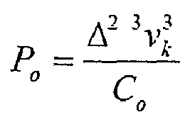
Model 1 CPS powered boat has the same boat body, tonnage Δ, and coefficient Co as the data used for the CAT-3516 engine, the cruising speed, vkl , is calculated using:
model 1. The cruising range ofmodel 1 is therefore given by C r1 = ν k1 • O t1 where Ot1 is the maximum working time. - It can be seen that for the same total power, the work output of
model 1 CPS for propulsion is ∼22.6% lower than that of CAT-3516, while the cruising speed and range decrease only by ∼8%. Furthermore,model 1 CPS provides -169.6 kW heat, 962.0kW refrigeration cold and 962.0kW cold for air conditioning at the same time. - Similarly, the cruising speed and range for
CPS models 2 to 4 powered boat can be obtained according to the data of CAT-3126. The cruising speed and range for aCPS model 2 powered boat are:
CPS model 3 powered boat are:
CPS model 4 powered boat are:
models 2 to 4 for propulsion are ∼2.8% lower than those of the corresponding diesel engine. However,models 2 to 4 can provide 22.0 kW, 6.5 kW and 2.1 kW heat at the same time, respectively. It can be seen that the cruising speed and the range ofmodels 2 to 4 of the CPS are ∼99.0% of those of the corresponding diesel engines. - Similarly, the cruising speed and range for a
CPS model 5 powered boat can be obtained according to the data of the Riverliner. The cruising speed and range for aCPS model 5 powered boat are:
CPS model 5 provides ∼45.2 kW heat, 256.8 kW refrigeration cold and 51.4 kW cold for air conditioning although the total power is 14.8 % higher than that of the corresponding diesel engine. - The flow rate of the fuel (liquid air) can be calculated by:


- The maximum heat transfer requirement has been analysed and estimated above. For the CPS with a unit work output (1kW), the heat transfer requirement is: Q = 2.184kW. The size of the heat transfers exchangers for a unit work output is: V = 0.011m 3. If a factor of safety is given as 4, the size of the heat transfer exchangers for a unit work output would be 0.044 m 3.
- On the basis of above data, a conservative estimation of the total volume of heat exchangers for
models 1 to 5 CPS are listed in table 5. - Energy density and price: A comparison between tables 4 and 5 shows that the fuel consumptions of
models 1 to 5 CPS are 37.70, 44.36, 42.08, 42.5 and 42.3 times those of the corresponding diesel engines respectively. Therefore, the energy densities ofmodels 1 to 5 are 1/37.70, 1/44.36, 1/42.08, 1/42.5 and 1/42.3 of those of the corresponding diesel engines. - To compare the price of specific power of the eight engines, the price of electricity is taken as Price_e =6 pence/kWh and that of diesel as Price_d=90 pence/litre, the energy consumption to produce 1 kg of liquid air is taken as 0.4 kWh (W. F. Castle. 2002). The price of the specific power (Price_p) of the four models is calculated as: CAT-3516 = 22.0 p/kWh, M1 = 25.0 p/kWh, CAT-3126 = 23.4 p/kWh, M2 = 31.3 p/kWh, Ford Porbeagle = 24.7 p/kWh, M3 = 31.3 p/kWh, Lister Petter ST3 = 24.8 p/kWh, M4 = 31.3 p/kWh, Cummins = 22.1 p/kWh, and M5 = 28.8 p/kWh.
- The price of specific power for the CPS models is comparable to the corresponding diesel models. If
model 1 CPS is used for boats for transportation of frozen materials, the price of specific power would be very competitive to the counterpart diesel model. - If the energy consumption to produce 1 kg of liquid air is taken as 0.3 kWh, then the price of specific power (Price_p) for
models 1 to 4 CPS become respectively 18.8, 23.4, 23.4, 23.4 and 21.6 p/kWh . - Energy Efficiency: The comparison of well-to-wheel efficiencies among the five models is shown in table 6. The CPS data is based on 0.4 kWh to produce 1 kg liquid air. It can be seen that the efficiency of
model 1 CPS is similar to that of CAT-3516 and the efficiency ofmodels 2 to 4 CPS using liquid air as fuel is lower than that of the corresponding diesel engines. The medium sized CPS boats have a higher efficiency when used for transportation of frozen materials than the small yachts do because the small yachts do not fully recover the cold. The efficiencies ofCPS models 1 to 4 shown in brackets is that if the consumption of producing 1 kg liquid air is taken to be 0.3 kWh.Table 6 Model CAT-3516 Model 1 CPSCAT-3126 Ford Porbeagle Lister Petter ST3 Models 2 to 4 CPS Cummins Riverliner Model 5 CPS Fuel Diesel Liquid Air Diesel Liquid Air Diesel Liquid Air Fuel production efficiency 94% 51.6% (68.8%) 94% 51.6% (68.8%) 94% 51.6% (68.8%) Peak brake engine efficiency or stack efficiency 38% 59.4% 38% 47.3% 38% 52.8% Part load efficiency factor 70% 70% 70% 70% 70% 70% Transmission efficiency 85% 80% 85% 90% 85% 80% Weight factor X Idle factor 100% 100% 100% 100% 100% 100% Total cycle efficiency 21% 18% (24%) 21% 15% (20%) 21% 16% (21%) - Life time and capital cost: Since all major components of the CPS are similar to the CES, the life time of a CPS system is also estimated to be about 20 to 40 years. The life time of the Diesel is considered to be about 17 years. However, it is believed that the life time of CPS is higher than that of diesel engines because there is no combustion process at high temperatures involved in CPS, and there is no strong friction between pistons and cylinders.
- It is believed that the CPS is competitive in terms of capital cost because there is little special requirement in terms of components. In addition, a refrigeration system is made obsolete in the case of refrigeration transportation boats.
- Influences of systems on the environment: Diesel engines involve combustion of fossil fuels and hence lead to emission of contaminates. CPS is a totally zero emission and environmentally benign system. If liquid air is produced by renewable energy, the CPS system would be a complete 'Green' power system. Furthermore, contaminates can be removed during liquefaction process, which would help with mitigating the negative environmental issues associated with burning of fossil fuels. Undesirable airborne particulates can also be removed during production of liquid air.
- Accordingly, Cryogenic Propulsion System (CPS) using liquid air can be used to provide combustion free and non-polluting maritime transportation. CPS has a competitive performance against the diesel engines in terms of energy price, energy efficiency, life time and capital cost and impact on the environment. CPS can have a higher efficiency if the cold energy is recovered for e.g. on-boat refrigeration and air-conditioning.
- It will of course be understood that the present invention has been described by way of example, and that modifications of detail can be made within the scope of the invention as defined by the following claims.
Claims (17)
- A method of storing energy using a cryogenic energy storage system having a first (340) and a second (350) heat exchanger, said method comprising the steps of:1) providing a gaseous input (120), wherein the gaseous input is air;2) producing a cryogen (250) from the gaseous input, wherein the cryogen is liquid air, and comprising:compressing, in a compressor (310), the gaseous input; andafter the compressed gaseous input has been cooled in the first (340) and the second (350) heat exchanger, feeding the compressed gaseous input to a throttling valve (360) to convert the compressed gaseous input into cryogen;3) storing the cryogen;4) pumping the cryogen to a form a pressurised cryogen;5) heating the pressurised cryogen in the second heat exchanger (350) using heat from the compressed gaseous input;6) superheating the heated pressurised cryogen in the first heat exchanger (340) using heat from the compressed gaseous input;7) expanding the superheated cryogen through a turbine (320) to drive the turbine; and8) recovering cold energy by recycling at least a portion of the cold energy contained in the cryogen by extracting said cold energy through said first (340) and second (350) heat exchangers to cool down the compressed gaseous input, thereby using the recovered cold energy to enhance production of more cryogen,wherein steps 1 and 2 occur simultaneously with steps 4 to 8.
- The method of claim 1 further comprising using the turbine (320, 510) to drive a generator (330, 515) and generate electricity.
- The method of claim 1 further comprising using the turbine (320, 510) to drive a propeller (505).
- The method of any preceding claim wherein the step of expanding the cryogen comprises heating the cryogen using: ambient heat; or geothermal heat; or waste heat from a power plant, from a steam stream, from the flue gas of a power plant or from another waste heat resource.
- The method of claim 4 wherein the step of expanding the cryogen comprises heating the cryogen using waste heat generated during the step of compressing the gaseous input.
- The method of any of claims 1 to 4 wherein the step of expanding the cryogen comprises:heating the cryogen to approximately the environmental temperature using ambient air; thenheating the cryogen further using waste heat.
- The method of any preceding claim wherein the cryogen is stored at an increased temperature prior to expansion.
- The method of any preceding claim further comprising using the recovered cold energy.
- The method of any preceding claim further comprising using the recovered cold energy for refrigeration or for air conditioning.
- The method of any preceding claim further comprising using waste heat generated during the step of producing the cryogen to provide: hot air for heating; or hot water.
- A cryogenic energy storage system (300) comprising:a gaseous input (120), wherein the gaseous input is air;means for producing cryogen from the gaseous input, wherein the cryogen is liquid air, the means comprising:a compressor (310) for compressing the gaseous input; anda throttling valve (360) arranged to convert the compressed gaseous input into a cryogen after the compressed gaseous input has been cooled in a first (340) and a second (350) heat exchanger;a cryogen storage facility (370);a pump arranged (380) for increasing the pressure of the cryogen by pumping the cryogen from the cryogen storage facility;the first heat exchanger (340) and the second heat exchanger (350), wherein the second heat exchanger (350) is arranged for heating the cryogen using heat from the compressed gaseous input after the pressure has been increased by the pump (380); andthe first heat exchanger (340) is arranged for superheating the cryogen using heat from the compressed gaseous input after the cryogen has been heated by the second heat exchanger (350);a turbine (320) for expanding the cryogen and capable of being driven by the expanding cryogen; andwhereby in use, cold energy is recovered by recycling at least a portion of the cold energy contained in the cryogen by extracting said cold energy through said first and second heat exchangers to cool down the compressed gaseous input, thereby using the recovered cold energy to enhance production of more cryogen,wherein the means for producing cryogen, the first heat exchanger, the second heat exchanger, and the turbine are configured to operate simultaneously.
- The cryogenic energy storage system of claim 11 further comprising a generator (330, 515) wherein the generator (330, 515) is capable of being driven by the turbine (320, 510).
- The cryogenic energy storage system of claim 11 further comprising a propeller (505) wherein the propeller (505) is capable of being driven by the turbine (320, 510).
- The cryogenic energy storage system of claim 11 wherein the first heat exchanger (340) is arranged to superheat the cryogen using: heat from ambient air; or geothermal heat; or waste heat from a power plant, from a steam stream, from the flue gas of a power plant or from another waste heat resource.
- The cryogenic energy storage system of claim 11 wherein:the second heat exchanger (350) is arranged to heat the cryogen to approximately the environmental temperature using ambient air; andthe first heat exchanger (340) is arranged to heat the cryogen further using waste heat.
- The cryogenic energy storage system of any of claims 11 to 15 wherein the turbine (320, 510) comprises a multi-stage quasi-isothermal turbine.
- The method of any of claims 1 to 10 wherein the turbine (320, 510) comprises a multi-stage quasi-isothermal turbine.
Applications Claiming Priority (4)
| Application Number | Priority Date | Filing Date | Title |
|---|---|---|---|
| GB0603895A GB0603895D0 (en) | 2006-02-27 | 2006-02-27 | Energy storage system |
| GB0608959A GB0608959D0 (en) | 2006-05-05 | 2006-05-05 | Electricity energy storage |
| GB0621972A GB0621972D0 (en) | 2006-11-03 | 2006-11-03 | Cryogenic propulsion system |
| PCT/GB2007/000667 WO2007096656A1 (en) | 2006-02-27 | 2007-02-27 | A method of storing energy and a cryogenic energy storage system |
Publications (3)
| Publication Number | Publication Date |
|---|---|
| EP1989400A1 EP1989400A1 (en) | 2008-11-12 |
| EP1989400B1 EP1989400B1 (en) | 2017-04-05 |
| EP1989400B2 true EP1989400B2 (en) | 2023-06-28 |
Family
ID=38093272
Family Applications (1)
| Application Number | Title | Priority Date | Filing Date |
|---|---|---|---|
| EP07712790.0A Active EP1989400B2 (en) | 2006-02-27 | 2007-02-27 | A method of storing energy and a cryogenic energy storage system |
Country Status (9)
| Country | Link |
|---|---|
| US (2) | US20090282840A1 (en) |
| EP (1) | EP1989400B2 (en) |
| JP (1) | JP2009528469A (en) |
| AU (1) | AU2007217133B2 (en) |
| CA (1) | CA2643742C (en) |
| ES (1) | ES2625284T5 (en) |
| PL (1) | PL1989400T5 (en) |
| TW (1) | TW200813320A (en) |
| WO (1) | WO2007096656A1 (en) |
Families Citing this family (136)
| Publication number | Priority date | Publication date | Assignee | Title |
|---|---|---|---|---|
| US7024800B2 (en) * | 2004-07-19 | 2006-04-11 | Earthrenew, Inc. | Process and system for drying and heat treating materials |
| US8648481B2 (en) * | 2006-06-10 | 2014-02-11 | Star Sailor Energy, Inc. | Wind generator with energy enhancer element for providing energy at no wind and low wind conditions |
| US11644010B1 (en) | 2006-06-10 | 2023-05-09 | Star Sailor Energy, Inc. | Energy storage system |
| US7958731B2 (en) | 2009-01-20 | 2011-06-14 | Sustainx, Inc. | Systems and methods for combined thermal and compressed gas energy conversion systems |
| US8474255B2 (en) | 2008-04-09 | 2013-07-02 | Sustainx, Inc. | Forming liquid sprays in compressed-gas energy storage systems for effective heat exchange |
| US8225606B2 (en) | 2008-04-09 | 2012-07-24 | Sustainx, Inc. | Systems and methods for energy storage and recovery using rapid isothermal gas expansion and compression |
| US8479505B2 (en) | 2008-04-09 | 2013-07-09 | Sustainx, Inc. | Systems and methods for reducing dead volume in compressed-gas energy storage systems |
| US7802426B2 (en) | 2008-06-09 | 2010-09-28 | Sustainx, Inc. | System and method for rapid isothermal gas expansion and compression for energy storage |
| US8448433B2 (en) | 2008-04-09 | 2013-05-28 | Sustainx, Inc. | Systems and methods for energy storage and recovery using gas expansion and compression |
| US20100307156A1 (en) | 2009-06-04 | 2010-12-09 | Bollinger Benjamin R | Systems and Methods for Improving Drivetrain Efficiency for Compressed Gas Energy Storage and Recovery Systems |
| US8677744B2 (en) | 2008-04-09 | 2014-03-25 | SustaioX, Inc. | Fluid circulation in energy storage and recovery systems |
| US8250863B2 (en) | 2008-04-09 | 2012-08-28 | Sustainx, Inc. | Heat exchange with compressed gas in energy-storage systems |
| US8359856B2 (en) | 2008-04-09 | 2013-01-29 | Sustainx Inc. | Systems and methods for efficient pumping of high-pressure fluids for energy storage and recovery |
| US8240140B2 (en) | 2008-04-09 | 2012-08-14 | Sustainx, Inc. | High-efficiency energy-conversion based on fluid expansion and compression |
| EP2280841A2 (en) | 2008-04-09 | 2011-02-09 | Sustainx, Inc. | Systems and methods for energy storage and recovery using compressed gas |
| US8037678B2 (en) | 2009-09-11 | 2011-10-18 | Sustainx, Inc. | Energy storage and generation systems and methods using coupled cylinder assemblies |
| WO2009139926A1 (en) * | 2008-05-16 | 2009-11-19 | Potomac Energy Projects, Llc | Hybrid solar collector and geothermal system |
| US7870746B2 (en) | 2008-05-27 | 2011-01-18 | Expansion Energy, Llc | System and method for liquid air production, power storage and power release |
| US7821158B2 (en) * | 2008-05-27 | 2010-10-26 | Expansion Energy, Llc | System and method for liquid air production, power storage and power release |
| US8063511B2 (en) | 2008-05-27 | 2011-11-22 | Expansion Energy, Llc | System and method for liquid air production, power storage and power release |
| DK3002422T3 (en) * | 2008-06-25 | 2020-05-04 | Siemens Ag | Energy storage system and method for storing and supplying energy |
| WO2010105155A2 (en) | 2009-03-12 | 2010-09-16 | Sustainx, Inc. | Systems and methods for improving drivetrain efficiency for compressed gas energy storage |
| US20100244455A1 (en) * | 2009-03-30 | 2010-09-30 | Berginc Michael J | Renewable energy electric power generation system derived from mechanical sources |
| EP2236822A1 (en) * | 2009-04-01 | 2010-10-06 | Werner Hermeling | On-demand method for regulating and smoothing the electric output of an energy convertor and device for carrying out this method |
| US8104274B2 (en) | 2009-06-04 | 2012-01-31 | Sustainx, Inc. | Increased power in compressed-gas energy storage and recovery |
| ES2562253T3 (en) * | 2009-06-24 | 2016-03-03 | Vestas Wind Systems A/S | A procedure and a system to control the operation of a wind turbine |
| WO2011056855A1 (en) | 2009-11-03 | 2011-05-12 | Sustainx, Inc. | Systems and methods for compressed-gas energy storage using coupled cylinder assemblies |
| CN102052256B (en) | 2009-11-09 | 2013-12-18 | 中国科学院工程热物理研究所 | Supercritical air energy storage system |
| US20110214986A1 (en) * | 2010-03-08 | 2011-09-08 | Michael Belford Brown | Clean water and clean air project (brine): method of water treatment, chemical production, and underground energy storage |
| US20110225987A1 (en) * | 2010-03-21 | 2011-09-22 | Boyd Bowdish | Self generating power generator for cryogenic systems |
| US8171728B2 (en) | 2010-04-08 | 2012-05-08 | Sustainx, Inc. | High-efficiency liquid heat exchange in compressed-gas energy storage systems |
| US8191362B2 (en) | 2010-04-08 | 2012-06-05 | Sustainx, Inc. | Systems and methods for reducing dead volume in compressed-gas energy storage systems |
| US8234863B2 (en) | 2010-05-14 | 2012-08-07 | Sustainx, Inc. | Forming liquid sprays in compressed-gas energy storage systems for effective heat exchange |
| US8978380B2 (en) | 2010-08-10 | 2015-03-17 | Dresser-Rand Company | Adiabatic compressed air energy storage process |
| BR112013003382B1 (en) | 2010-08-12 | 2020-11-10 | Highview Enterprises Limited | method for integrating a first thermal process, a second thermal process and a third thermal process |
| US8495872B2 (en) | 2010-08-20 | 2013-07-30 | Sustainx, Inc. | Energy storage and recovery utilizing low-pressure thermal conditioning for heat exchange with high-pressure gas |
| US8578708B2 (en) | 2010-11-30 | 2013-11-12 | Sustainx, Inc. | Fluid-flow control in energy storage and recovery systems |
| US10100979B2 (en) * | 2010-12-17 | 2018-10-16 | L'air Liquide Societe Anonyme Pour L'etude Et L'exploitation Des Procedes Georges Claude | Liquid air as energy storage |
| GB201100569D0 (en) | 2011-01-13 | 2011-03-02 | Highview Entpr Ltd | Electricity generation device and method |
| DE102011013577B4 (en) * | 2011-03-10 | 2013-02-28 | Karlsruher Institut für Technologie | Device for storing hydrogen and magnetic energy and a method for their operation |
| JP2014522460A (en) | 2011-05-17 | 2014-09-04 | サステインエックス, インコーポレイテッド | System and method for efficient two-phase heat transfer in a compressed air energy storage system |
| GB2494400B (en) | 2011-09-06 | 2017-11-22 | Highview Entpr Ltd | Method and apparatus for power storage |
| US20130091834A1 (en) | 2011-10-14 | 2013-04-18 | Sustainx, Inc. | Dead-volume management in compressed-gas energy storage and recovery systems |
| CN104246150B (en) * | 2011-10-22 | 2017-04-12 | 可持续能源解决方案有限公司 | Systems and methods for integrated energy storage and cryogenic carbon capture |
| TWI482903B (en) * | 2011-12-06 | 2015-05-01 | Hon Hai Prec Ind Co Ltd | Module of combustion turbine engine |
| ITRM20110658A1 (en) * | 2011-12-11 | 2012-03-11 | Silvano Mattioli | ELECTRICITY ACCUMULATION SYSTEM THROUGH WARM AND COLD STORAGE TANKS AND EFFICIENT ENERGY GENERATION FROM LOW ENTALPIA SOURCES |
| DE102011121011A1 (en) | 2011-12-13 | 2013-06-13 | Linde Aktiengesellschaft | Method and device for generating electrical energy |
| US9294026B2 (en) * | 2011-12-20 | 2016-03-22 | United Technologies Corporation | Method of operating a power generation system |
| WO2013102537A2 (en) * | 2012-01-03 | 2013-07-11 | Abb Research Ltd | Electro-thermal energy storage system with improved evaporative ice storage arrangement and method for storing electro-thermal energy |
| DE102012104416A1 (en) | 2012-03-01 | 2013-09-05 | Institut Für Luft- Und Kältetechnik Gemeinnützige Gmbh | Method and arrangement for storing energy |
| US20140150418A1 (en) * | 2012-05-04 | 2014-06-05 | Branko Bem | Regenerating Generator |
| EP2662552A1 (en) | 2012-05-08 | 2013-11-13 | Linde Aktiengesellschaft | Device and method for generating electrical energy |
| KR20150028332A (en) | 2012-06-28 | 2015-03-13 | 린데 악티엔게젤샤프트 | Process and apparatus for generating electric energy |
| WO2014019698A2 (en) | 2012-08-02 | 2014-02-06 | Linde Aktiengesellschaft | Method and device for generating electrical energy |
| EP2880268A2 (en) | 2012-08-02 | 2015-06-10 | Linde Aktiengesellschaft | Method and device for generating electrical energy |
| US9719423B2 (en) | 2012-09-04 | 2017-08-01 | General Electric Company | Inlet air chilling system with humidity control and energy recovery |
| US20140130521A1 (en) * | 2012-11-12 | 2014-05-15 | Fluor Technologies Corporation | Configurations and Methods for Ambient Air Vaporizers and Cold Utilization |
| US9938895B2 (en) | 2012-11-20 | 2018-04-10 | Dresser-Rand Company | Dual reheat topping cycle for improved energy efficiency for compressed air energy storage plants with high air storage pressure |
| WO2014146796A1 (en) * | 2013-03-21 | 2014-09-25 | Linde Aktiengesellschaft | Method and device for generating electrical energy |
| GB2512360B (en) | 2013-03-27 | 2015-08-05 | Highview Entpr Ltd | Method and apparatus in a cryogenic liquefaction process |
| US8907524B2 (en) | 2013-05-09 | 2014-12-09 | Expansion Energy Llc | Systems and methods of semi-centralized power storage and power production for multi-directional smart grid and other applications |
| CN103323144B (en) * | 2013-06-09 | 2015-09-16 | 浙江大学 | A kind of method of fruit tree being carried out to freezing early warning |
| WO2015006606A1 (en) * | 2013-07-12 | 2015-01-15 | David Randolph Smith | Method and apparatus for enhancing recovery and storage of energy from renewable energy sources using a cryogenic pump |
| US20150033721A1 (en) * | 2013-07-30 | 2015-02-05 | Scott Clair Pockrandt | Liquid Nitrogen Conventional Generator |
| EP2835507B1 (en) | 2013-08-09 | 2016-09-21 | Linde Aktiengesellschaft | Method for generating electrical energy and energy generation system |
| EP2835506A1 (en) | 2013-08-09 | 2015-02-11 | Linde Aktiengesellschaft | Method for generating electrical energy and energy generation system |
| US10197338B2 (en) * | 2013-08-22 | 2019-02-05 | Kevin Hans Melsheimer | Building system for cascading flows of matter and energy |
| FR3012876A1 (en) * | 2013-11-07 | 2015-05-08 | Air Liquide | METHOD AND APPARATUS FOR COOLING AIR TO BE SEPARATED BY CRYOGENIC DISTILLATION |
| FR3015555A1 (en) * | 2013-12-20 | 2015-06-26 | Air Liquide | METHOD AND APPARATUS FOR GENERATING ELECTRICITY USING A THERMAL OR NUCLEAR POWER PLANT |
| CH709010A1 (en) * | 2013-12-20 | 2015-06-30 | Josef Mächler | Thermal power plant with heat recovery. |
| US10473029B2 (en) | 2013-12-30 | 2019-11-12 | William M. Conlon | Liquid air power and storage |
| US10480353B2 (en) * | 2014-02-21 | 2019-11-19 | University Of Florida Research Foundation, Inc. | Cryogenic power extraction |
| US20150300209A1 (en) * | 2014-03-24 | 2015-10-22 | Mada Energie Llc | Systems, methods, and devices for power storage, recovery, and balancing |
| DE102014105237B3 (en) | 2014-04-11 | 2015-04-09 | Mitsubishi Hitachi Power Systems Europe Gmbh | Method and device for storing and recovering energy |
| EP2930322A1 (en) | 2014-04-11 | 2015-10-14 | Linde Aktiengesellschaft | Method and system for storing and recovering energy |
| EP2930318A1 (en) | 2014-04-11 | 2015-10-14 | Linde Aktiengesellschaft | Method and system for storing and recovering energy |
| GB201409669D0 (en) | 2014-05-30 | 2014-07-16 | Highview Entpr Ltd | Improvements in air purification units |
| EP3032203A1 (en) | 2014-12-09 | 2016-06-15 | Linde Aktiengesellschaft | Method and combination system for storing and recovering energy |
| EP3034974A1 (en) | 2014-12-09 | 2016-06-22 | Linde Aktiengesellschaft | Method and assembly for the liquefaction of air and for electrical energy storage and recovery |
| DE102015109898A1 (en) * | 2015-02-20 | 2016-08-25 | Mitsubishi Hitachi Power Systems Europe Gmbh | Steam power plant and method for its operation |
| JP6510876B2 (en) * | 2015-05-01 | 2019-05-08 | 株式会社神戸製鋼所 | Compressed air storage power generation method and compressed air storage power generation device |
| GB2538784A (en) * | 2015-05-28 | 2016-11-30 | Highview Entpr Ltd | Improvements in energy storage |
| WO2016195968A1 (en) | 2015-06-01 | 2016-12-08 | Conlon William M | Part load operation of liquid air power and storage system |
| WO2016195999A1 (en) | 2015-06-03 | 2016-12-08 | Conlon William M | Liquid air power and storage with carbon capture |
| WO2016204893A1 (en) | 2015-06-16 | 2016-12-22 | Conlon William M | Cryogenic liquid energy storage |
| US20170038131A1 (en) * | 2015-08-05 | 2017-02-09 | Joseph Naumovitz | Cold storage methods |
| EP3365536B1 (en) | 2015-10-21 | 2020-11-18 | William M. Conlon | High pressure liquid air power and storage |
| EP3196573A1 (en) | 2016-01-21 | 2017-07-26 | Linde Aktiengesellschaft | Method for obtaining an air product and air decomposition system |
| GB201601878D0 (en) | 2016-02-02 | 2016-03-16 | Highview Entpr Ltd | Improvements in power recovery |
| US11384962B2 (en) * | 2016-06-13 | 2022-07-12 | Geoff ROWE | System, method and apparatus for the regeneration of nitrogen energy within a closed loop cryogenic system |
| DE102016009254A1 (en) | 2016-07-29 | 2018-02-01 | Linde Aktiengesellschaft | Process for storing and recovering energy |
| EP3293475A1 (en) | 2016-09-07 | 2018-03-14 | Linde Aktiengesellschaft | Method and system for storing and regaining energy |
| RU170011U1 (en) * | 2016-11-22 | 2017-04-11 | федеральное государственное автономное образовательное учреждение высшего образования "Самарский национальный исследовательский университет имени академика С.П. Королева" | Cryogenic Gasifier Pump |
| DE102016015292A1 (en) | 2016-12-22 | 2018-06-28 | Linde Aktiengesellschaft | Method of providing one or more air products with an air separation plant |
| CN106697187B (en) * | 2016-12-26 | 2018-10-09 | 武汉理工大学 | Ship power system Work condition analogue based on intelligent cabin and diagnostic test platform |
| JP6347003B1 (en) * | 2017-01-25 | 2018-06-20 | デウ シップビルディング アンド マリン エンジニアリング カンパニー リミテッド | LNG ship evaporative gas reliquefaction method and system |
| IT201700008681A1 (en) * | 2017-01-26 | 2018-07-26 | Nuovo Pignone Tecnologie Srl | GAS TURBINE SYSTEM |
| JP6764798B2 (en) | 2017-01-30 | 2020-10-07 | 三菱重工業株式会社 | Plant and plant operation method |
| US12111100B2 (en) * | 2017-03-14 | 2024-10-08 | Woodside Energy Technologies Pty Ltd | Containerised LNG liquefaction unit and associated method of producing LNG |
| US10508596B2 (en) | 2017-06-21 | 2019-12-17 | John D. Upperman | System and method for liquid air energy storage |
| US12157685B2 (en) | 2017-08-31 | 2024-12-03 | Energy Internet Corporation | Liquid purification with pressure vessels |
| US12155205B2 (en) | 2017-08-31 | 2024-11-26 | Energy Internet Corporation | Energy transfer using high-pressure vessel |
| US11906224B2 (en) | 2017-08-31 | 2024-02-20 | Energy Internet Corporation | Controlled refrigeration and liquefaction using compatible materials for energy management |
| US10634013B2 (en) | 2017-09-05 | 2020-04-28 | Stanislav Sinatov | Method for liquid air energy storage with semi-closed CO2 bottoming cycle |
| US20200277896A1 (en) * | 2017-09-27 | 2020-09-03 | Universidad Técnica Federico Santa María | System and method to store and generate energy where a pressure is released into a liquid circuit which in turn moves a liquid turbine to generate power |
| TWI655363B (en) * | 2017-11-02 | 2019-04-01 | 李忠諭 | Energy storage and release apparatus and method for energy storage and release |
| GB2570946B (en) * | 2018-02-13 | 2021-03-10 | Highview Entpr Ltd | Heat-of-compression recycle system, and sub-systems thereof |
| WO2019202731A1 (en) * | 2018-04-20 | 2019-10-24 | 三菱電機株式会社 | Vehicle heat exchange system and vehicle air conditioning system |
| US10813254B2 (en) * | 2018-07-13 | 2020-10-20 | Christopher Marazzo | Thermal management and power system for computing infrastructure |
| US10731792B2 (en) * | 2018-10-01 | 2020-08-04 | Mark Cann | System and method for storage of cryogenic material |
| GB2580591B (en) | 2019-01-14 | 2022-09-21 | Bae Systems Plc | Heat sink for electrical device |
| IT201900002385A1 (en) | 2019-02-19 | 2020-08-19 | Energy Dome S P A | Plant and process for the accumulation of energy |
| CN109856966B (en) * | 2019-03-13 | 2020-05-22 | 西安交通大学 | A method for controlling the amount of coal fed with transient variable load taking into account the storage* correction of coal-fired boilers |
| DE102019001876B3 (en) * | 2019-03-15 | 2020-06-10 | Tivadar Menyhart | Method, device and system for operating internal combustion engines with a significantly increased pressure ratio and vehicle with this system |
| TWI725643B (en) * | 2019-12-02 | 2021-04-21 | 翁維嵩 | Mechanical device and its operation method |
| CN113120836A (en) * | 2019-12-30 | 2021-07-16 | 赫普能源环境科技有限公司 | Filling and recycling system and method for liquid electric fuel of gas station |
| CA3181981A1 (en) | 2020-01-25 | 2021-02-12 | Matthew Toews | Method for on demand power production utilizing geologic thermal recovery |
| IT202000003680A1 (en) | 2020-02-21 | 2021-08-21 | Energy Dome S P A | Plant and process for the accumulation of energy |
| CU20220056A7 (en) * | 2020-03-24 | 2023-05-11 | Energy Dome S P A | PLANT AND PROCESS FOR THE GENERATION AND STORAGE OF ENERGY |
| CN111486344B (en) * | 2020-04-02 | 2021-12-17 | 江苏国富氢能技术装备股份有限公司 | Container skid-mounted compression hydrogenation device |
| CN111521430B (en) * | 2020-06-09 | 2021-09-28 | 国网安徽省电力有限公司电力科学研究院 | Waste heat boiler performance test method |
| CN112009697A (en) * | 2020-09-02 | 2020-12-01 | 成都精智艺科技有限责任公司 | Efficient LNG ship power supply system and method |
| AU2020469637A1 (en) | 2020-09-25 | 2023-04-27 | Energy Dome S.P.A. | Plant and process for energy storage |
| CN113670003B (en) * | 2021-07-29 | 2022-08-09 | 北京科技大学 | High-safety energy storage, power generation and substance recovery external compression air separation process flow |
| US12162360B2 (en) * | 2021-08-17 | 2024-12-10 | Brunswick Corporation | Electric marine propulsion system and control method |
| FR3127254B1 (en) * | 2021-09-23 | 2023-10-06 | Eclair Conseil | Open cycle cogeneration process. |
| FR3127277A1 (en) * | 2021-10-27 | 2023-03-24 | Airbus Operations | INERT GAS GENERATION SYSTEM FOR AIRCRAFT USING LIQUID HYDROGEN. |
| EP4441343A1 (en) | 2021-12-03 | 2024-10-09 | Power8 Tech Inc. | Energy storage systems and methods using heterogeneous pressure media and interactive actuation module |
| US12253285B2 (en) | 2021-12-03 | 2025-03-18 | Power8 Tech. Inc. | Geothermal energy storage and conversion systems and methods |
| US12180919B2 (en) | 2021-12-03 | 2024-12-31 | Power8 Tech. Inc. | Power tunnel |
| US12234797B2 (en) | 2021-12-03 | 2025-02-25 | Powers8 TECH INC. | Smart controlling systems for energy storage |
| JP2023172944A (en) | 2022-05-24 | 2023-12-06 | 石井 克和 | Compressed-air energy storage method |
| CN119630919A (en) | 2022-08-01 | 2025-03-14 | 东洋工程株式会社 | Compressed air storage container and compressed air storage device including the same |
| WO2024037746A1 (en) | 2022-08-19 | 2024-02-22 | Phelas Gmbh | Thermal energy storage, system and method |
| FR3148081A1 (en) * | 2023-04-19 | 2024-10-25 | Engie | DEVICE AND METHOD FOR PRE-COOLING A TARGET FLUID TO BE LIQUEFIED |
| DE102023123335A1 (en) | 2023-08-30 | 2025-03-06 | Deutsches Zentrum für Luft- und Raumfahrt e.V. | heat storage system, especially cryogenic heat storage system |
Family Cites Families (42)
| Publication number | Priority date | Publication date | Assignee | Title |
|---|---|---|---|---|
| US2960834A (en) * | 1954-11-22 | 1960-11-22 | Garrett Corp | Production of liquid oxygen from atmospheric air |
| US3451342A (en) * | 1965-10-24 | 1969-06-24 | Everett H Schwartzman | Cryogenic engine system and method |
| US3830326A (en) * | 1972-12-13 | 1974-08-20 | R Hartung | Gas turbine automotive machine |
| GB1481682A (en) * | 1973-07-12 | 1977-08-03 | Nat Res Dev | Power systems |
| DE2434238A1 (en) | 1974-07-16 | 1976-01-29 | Linde Ag | System to store and retrieve stored energy - has gas type auxiliary energy storage medium which is liquefied when energy requirements are low |
| US4329842A (en) * | 1980-07-02 | 1982-05-18 | Hans D. Linhardt | Power conversion system utilizing reversible energy of liquefied natural gas |
| FR2489411A1 (en) * | 1980-08-29 | 1982-03-05 | Technigaz | Off peak energy storing system - has air liquefying and vaporising units to enable energy to be stored as liquid air in low volume |
| US4455834A (en) | 1981-09-25 | 1984-06-26 | Earle John L | Windmill power apparatus and method |
| US4695302A (en) * | 1986-10-28 | 1987-09-22 | Liquid Carbonic Corporation | Production of large quantities of CO2 snow |
| US4765143A (en) | 1987-02-04 | 1988-08-23 | Cbi Research Corporation | Power plant using CO2 as a working fluid |
| SU1710824A1 (en) | 1989-09-15 | 1992-02-07 | Днепропетровский государственный университет им.300-летия воссоединения Украины с Россией | Wind power plant |
| US4995234A (en) | 1989-10-02 | 1991-02-26 | Chicago Bridge & Iron Technical Services Company | Power generation from LNG |
| JP3040442B2 (en) | 1990-09-20 | 2000-05-15 | 三菱重工業株式会社 | Gas turbine power generation equipment |
| US5272879A (en) * | 1992-02-27 | 1993-12-28 | Wiggs B Ryland | Multi-system power generator |
| JP3460433B2 (en) | 1996-03-14 | 2003-10-27 | 株式会社日立製作所 | Energy storage type gas turbine power generation system |
| DE19757588A1 (en) | 1996-12-24 | 1998-07-02 | Hitachi Ltd | Electricity generating system with gas turbine and energy storage |
| US6920759B2 (en) * | 1996-12-24 | 2005-07-26 | Hitachi, Ltd. | Cold heat reused air liquefaction/vaporization and storage gas turbine electric power system |
| JPH10238367A (en) | 1997-02-24 | 1998-09-08 | Hitachi Ltd | Energy storage type gas turbine power generation system |
| DE19811315C2 (en) * | 1998-03-16 | 2000-08-03 | Steyr Daimler Puch Ag | Method and device for producing slush from liquefied gas |
| JPH11303646A (en) | 1998-04-20 | 1999-11-02 | Hitachi Ltd | Gas turbine power plant |
| JP2000130185A (en) | 1998-10-21 | 2000-05-09 | Hitachi Ltd | Energy storing type gas turbine power generation system |
| JP2001193483A (en) | 2000-01-12 | 2001-07-17 | Hitachi Ltd | Gas turbine system |
| US6349787B1 (en) * | 2000-05-08 | 2002-02-26 | Farouk Dakhil | Vehicle having a turbine engine and a flywheel powered by liquid nitrogen |
| US6282901B1 (en) | 2000-07-19 | 2001-09-04 | L'air Liquide, Societe Anonyme Pour L'etude Et L'exploitation Des Procedes Georges Claude | Integrated air separation process |
| US7043925B2 (en) * | 2001-01-17 | 2006-05-16 | Sierra Lobo, Inc. | Densifier for simultaneous conditioning of two cryogenic liquids |
| JP2002242694A (en) | 2001-02-20 | 2002-08-28 | Hitachi Ltd | Energy storing type gas turbine generator |
| US6745573B2 (en) | 2001-03-23 | 2004-06-08 | American Air Liquide, Inc. | Integrated air separation and power generation process |
| JP2002339760A (en) | 2001-05-16 | 2002-11-27 | Hitachi Ltd | Method and device for gas turbine power generation |
| US6827104B2 (en) * | 2001-10-24 | 2004-12-07 | Mcfarland Rory S. | Seal and valve systems and methods for use in expanders and compressors of energy conversion systems |
| JP4132837B2 (en) * | 2001-12-26 | 2008-08-13 | 三ツ星ベルト株式会社 | Metal mold manufacturing method |
| US6871502B2 (en) * | 2002-02-15 | 2005-03-29 | America Air Liquide, Inc. | Optimized power generation system comprising an oxygen-fired combustor integrated with an air separation unit |
| JP3762312B2 (en) * | 2002-02-26 | 2006-04-05 | 株式会社日立製作所 | Liquid air energy storage system and control method thereof |
| JP2004150685A (en) | 2002-10-30 | 2004-05-27 | Mitsubishi Heavy Ind Ltd | Nitrogen producing equipment and turbine power generation equipment |
| RU2337057C2 (en) * | 2003-03-11 | 2008-10-27 | Майекава Мфг. Ко., Лтд. | Method of nitrogen sludge production and device for its realisation |
| GB2409022B (en) * | 2003-12-13 | 2006-01-25 | Rolls Royce Plc | Work extraction arrangement |
| US20050135934A1 (en) * | 2003-12-22 | 2005-06-23 | Mechanology, Llc | Use of intersecting vane machines in combination with wind turbines |
| US7228715B2 (en) * | 2003-12-23 | 2007-06-12 | L'air Liquide, Societe Anonyme A Directoire Et Conseil De Surveillance Pour L'etude Et L'exploitation Des Procedes Georges Claude | Cryogenic air separation process and apparatus |
| US7406829B2 (en) * | 2004-06-18 | 2008-08-05 | General Electric Company | Cryogenic liquid oxidizer cooled high energy system |
| US7210312B2 (en) * | 2004-08-03 | 2007-05-01 | Sunpower, Inc. | Energy efficient, inexpensive extraction of oxygen from ambient air for portable and home use |
| US7047744B1 (en) * | 2004-09-16 | 2006-05-23 | Robertson Stuart J | Dynamic heat sink engine |
| GB0600384D0 (en) * | 2006-01-10 | 2006-02-15 | Highview Entpr Ltd | Cryogenic engines |
| WO2008024833A2 (en) | 2006-08-22 | 2008-02-28 | David Vandor | A combined cycle system for gas turbines and reciprocating engines and a method for the use of air as working fluid in combined cycle power plants |
-
2007
- 2007-02-27 EP EP07712790.0A patent/EP1989400B2/en active Active
- 2007-02-27 US US12/280,739 patent/US20090282840A1/en not_active Abandoned
- 2007-02-27 WO PCT/GB2007/000667 patent/WO2007096656A1/en active Application Filing
- 2007-02-27 ES ES07712790T patent/ES2625284T5/en active Active
- 2007-02-27 CA CA2643742A patent/CA2643742C/en active Active
- 2007-02-27 JP JP2008555877A patent/JP2009528469A/en active Pending
- 2007-02-27 AU AU2007217133A patent/AU2007217133B2/en active Active
- 2007-02-27 PL PL07712790.0T patent/PL1989400T5/en unknown
- 2007-02-27 TW TW096106888A patent/TW200813320A/en unknown
-
2016
- 2016-02-25 US US15/053,840 patent/US20160178129A1/en not_active Abandoned
Also Published As
| Publication number | Publication date |
|---|---|
| AU2007217133B2 (en) | 2013-05-30 |
| EP1989400A1 (en) | 2008-11-12 |
| AU2007217133A1 (en) | 2007-08-30 |
| PL1989400T5 (en) | 2023-10-09 |
| PL1989400T3 (en) | 2017-08-31 |
| US20090282840A1 (en) | 2009-11-19 |
| TW200813320A (en) | 2008-03-16 |
| EP1989400B1 (en) | 2017-04-05 |
| CA2643742A1 (en) | 2007-08-30 |
| ES2625284T3 (en) | 2017-07-19 |
| US20160178129A1 (en) | 2016-06-23 |
| WO2007096656A1 (en) | 2007-08-30 |
| CA2643742C (en) | 2014-08-26 |
| ES2625284T5 (en) | 2023-12-01 |
| JP2009528469A (en) | 2009-08-06 |
Similar Documents
| Publication | Publication Date | Title |
|---|---|---|
| EP1989400B2 (en) | A method of storing energy and a cryogenic energy storage system | |
| CN101427007B (en) | A method of storing energy and a cryogenic energy storage system | |
| Olympios et al. | Progress and prospects of thermo-mechanical energy storage—a critical review | |
| EP2753861B2 (en) | Method and apparatus for power storage | |
| US20030074900A1 (en) | Energy conversion method and system with enhanced heat engine | |
| US20080047271A1 (en) | Wind turbine system | |
| CN202811078U (en) | Ultra-supercritical air energy storage/release system | |
| US4227374A (en) | Methods and means for storing energy | |
| US20160333747A1 (en) | Prime Mover with Recovered Energy Induced Source and Sink Temperature | |
| US20050056018A1 (en) | Seal and valve systems and methods for use in expanders and compressors of energy conversion systems | |
| CN103016152A (en) | Supercritical air energy storage system with novel process | |
| KR20150115126A (en) | A Treatment System of Liquefied Gas | |
| IT201900008367A1 (en) | A NATURAL GAS LIQUEFACTION SYSTEM | |
| CN110206604A (en) | A kind of cryogenic fluid supercritical generating system or motor device | |
| WO2007136765A2 (en) | Wind turbine system | |
| WO2007136731A2 (en) | Wind turbine system | |
| US10508596B2 (en) | System and method for liquid air energy storage | |
| US10690013B2 (en) | System and method for liquid air energy storage | |
| CN103256081B (en) | Energy comprehensive utilization method based on supercritical air | |
| CN103266952B (en) | Based on the energy comprehensive utilization system of supercritical air | |
| RU2431047C2 (en) | Complex power plant | |
| CN101135252A (en) | Power technology | |
| US20250052233A1 (en) | NEW HYBRID POWER CYCLE FOR 100% CLEAN, AND CONTINUOUS (24x7) HAZARD-FREE LOW-COST POWER GENERATION AND TRANSPORTATION WITHOUT ANY FUEL AND USING ONLY AMBIENT THERMAL ENERGY | |
| CN219243966U (en) | Cold force energy conversion device | |
| CN201367998Y (en) | Low-temperature liquefied energy recovery power supply system |
Legal Events
| Date | Code | Title | Description |
|---|---|---|---|
| PUAI | Public reference made under article 153(3) epc to a published international application that has entered the european phase |
Free format text: ORIGINAL CODE: 0009012 |
|
| 17P | Request for examination filed |
Effective date: 20080917 |
|
| AK | Designated contracting states |
Kind code of ref document: A1 Designated state(s): AT BE BG CH CY CZ DE DK EE ES FI FR GB GR HU IE IS IT LI LT LU LV MC NL PL PT RO SE SI SK TR |
|
| RAP1 | Party data changed (applicant data changed or rights of an application transferred) |
Owner name: HIGHVIEW ENTERPRISES LIMITED |
|
| DAX | Request for extension of the european patent (deleted) | ||
| RAP1 | Party data changed (applicant data changed or rights of an application transferred) |
Owner name: HIGHVIEW ENTERPRISES LIMITED |
|
| 17Q | First examination report despatched |
Effective date: 20150120 |
|
| GRAP | Despatch of communication of intention to grant a patent |
Free format text: ORIGINAL CODE: EPIDOSNIGR1 |
|
| RIC1 | Information provided on ipc code assigned before grant |
Ipc: F02C 6/14 20060101ALI20160421BHEP Ipc: F01D 15/04 20060101ALI20160421BHEP Ipc: F02C 1/05 20060101ALI20160421BHEP Ipc: F01D 15/00 20060101AFI20160421BHEP |
|
| INTG | Intention to grant announced |
Effective date: 20160511 |
|
| GRAJ | Information related to disapproval of communication of intention to grant by the applicant or resumption of examination proceedings by the epo deleted |
Free format text: ORIGINAL CODE: EPIDOSDIGR1 |
|
| GRAP | Despatch of communication of intention to grant a patent |
Free format text: ORIGINAL CODE: EPIDOSNIGR1 |
|
| INTC | Intention to grant announced (deleted) | ||
| INTG | Intention to grant announced |
Effective date: 20160907 |
|
| STAA | Information on the status of an ep patent application or granted ep patent |
Free format text: STATUS: GRANT OF PATENT IS INTENDED |
|
| GRAS | Grant fee paid |
Free format text: ORIGINAL CODE: EPIDOSNIGR3 |
|
| GRAA | (expected) grant |
Free format text: ORIGINAL CODE: 0009210 |
|
| STAA | Information on the status of an ep patent application or granted ep patent |
Free format text: STATUS: THE PATENT HAS BEEN GRANTED |
|
| AK | Designated contracting states |
Kind code of ref document: B1 Designated state(s): AT BE BG CH CY CZ DE DK EE ES FI FR GB GR HU IE IS IT LI LT LU LV MC NL PL PT RO SE SI SK TR |
|
| REG | Reference to a national code |
Ref country code: GB Ref legal event code: FG4D |
|
| REG | Reference to a national code |
Ref country code: CH Ref legal event code: EP |
|
| REG | Reference to a national code |
Ref country code: AT Ref legal event code: REF Ref document number: 882037 Country of ref document: AT Kind code of ref document: T Effective date: 20170415 |
|
| REG | Reference to a national code |
Ref country code: IE Ref legal event code: FG4D |
|
| REG | Reference to a national code |
Ref country code: DE Ref legal event code: R096 Ref document number: 602007050468 Country of ref document: DE |
|
| REG | Reference to a national code |
Ref country code: NL Ref legal event code: FP |
|
| REG | Reference to a national code |
Ref country code: ES Ref legal event code: FG2A Ref document number: 2625284 Country of ref document: ES Kind code of ref document: T3 Effective date: 20170719 |
|
| REG | Reference to a national code |
Ref country code: LT Ref legal event code: MG4D |
|
| REG | Reference to a national code |
Ref country code: AT Ref legal event code: MK05 Ref document number: 882037 Country of ref document: AT Kind code of ref document: T Effective date: 20170405 |
|
| PG25 | Lapsed in a contracting state [announced via postgrant information from national office to epo] |
Ref country code: LT Free format text: LAPSE BECAUSE OF FAILURE TO SUBMIT A TRANSLATION OF THE DESCRIPTION OR TO PAY THE FEE WITHIN THE PRESCRIBED TIME-LIMIT Effective date: 20170405 Ref country code: GR Free format text: LAPSE BECAUSE OF FAILURE TO SUBMIT A TRANSLATION OF THE DESCRIPTION OR TO PAY THE FEE WITHIN THE PRESCRIBED TIME-LIMIT Effective date: 20170706 Ref country code: AT Free format text: LAPSE BECAUSE OF FAILURE TO SUBMIT A TRANSLATION OF THE DESCRIPTION OR TO PAY THE FEE WITHIN THE PRESCRIBED TIME-LIMIT Effective date: 20170405 Ref country code: FI Free format text: LAPSE BECAUSE OF FAILURE TO SUBMIT A TRANSLATION OF THE DESCRIPTION OR TO PAY THE FEE WITHIN THE PRESCRIBED TIME-LIMIT Effective date: 20170405 |
|
| PG25 | Lapsed in a contracting state [announced via postgrant information from national office to epo] |
Ref country code: LV Free format text: LAPSE BECAUSE OF FAILURE TO SUBMIT A TRANSLATION OF THE DESCRIPTION OR TO PAY THE FEE WITHIN THE PRESCRIBED TIME-LIMIT Effective date: 20170405 Ref country code: BG Free format text: LAPSE BECAUSE OF FAILURE TO SUBMIT A TRANSLATION OF THE DESCRIPTION OR TO PAY THE FEE WITHIN THE PRESCRIBED TIME-LIMIT Effective date: 20170705 Ref country code: IS Free format text: LAPSE BECAUSE OF FAILURE TO SUBMIT A TRANSLATION OF THE DESCRIPTION OR TO PAY THE FEE WITHIN THE PRESCRIBED TIME-LIMIT Effective date: 20170805 Ref country code: SE Free format text: LAPSE BECAUSE OF FAILURE TO SUBMIT A TRANSLATION OF THE DESCRIPTION OR TO PAY THE FEE WITHIN THE PRESCRIBED TIME-LIMIT Effective date: 20170405 |
|
| REG | Reference to a national code |
Ref country code: DE Ref legal event code: R026 Ref document number: 602007050468 Country of ref document: DE |
|
| PLBI | Opposition filed |
Free format text: ORIGINAL CODE: 0009260 |
|
| PLAX | Notice of opposition and request to file observation + time limit sent |
Free format text: ORIGINAL CODE: EPIDOSNOBS2 |
|
| PG25 | Lapsed in a contracting state [announced via postgrant information from national office to epo] |
Ref country code: EE Free format text: LAPSE BECAUSE OF FAILURE TO SUBMIT A TRANSLATION OF THE DESCRIPTION OR TO PAY THE FEE WITHIN THE PRESCRIBED TIME-LIMIT Effective date: 20170405 Ref country code: DK Free format text: LAPSE BECAUSE OF FAILURE TO SUBMIT A TRANSLATION OF THE DESCRIPTION OR TO PAY THE FEE WITHIN THE PRESCRIBED TIME-LIMIT Effective date: 20170405 Ref country code: CZ Free format text: LAPSE BECAUSE OF FAILURE TO SUBMIT A TRANSLATION OF THE DESCRIPTION OR TO PAY THE FEE WITHIN THE PRESCRIBED TIME-LIMIT Effective date: 20170405 Ref country code: SK Free format text: LAPSE BECAUSE OF FAILURE TO SUBMIT A TRANSLATION OF THE DESCRIPTION OR TO PAY THE FEE WITHIN THE PRESCRIBED TIME-LIMIT Effective date: 20170405 Ref country code: RO Free format text: LAPSE BECAUSE OF FAILURE TO SUBMIT A TRANSLATION OF THE DESCRIPTION OR TO PAY THE FEE WITHIN THE PRESCRIBED TIME-LIMIT Effective date: 20170405 |
|
| 26 | Opposition filed |
Opponent name: L'AIR LIQUIDE, SOCIETE ANONYME POUR L'ETUDE ET L'E Effective date: 20180103 |
|
| REG | Reference to a national code |
Ref country code: FR Ref legal event code: PLFP Year of fee payment: 12 |
|
| PG25 | Lapsed in a contracting state [announced via postgrant information from national office to epo] |
Ref country code: SI Free format text: LAPSE BECAUSE OF FAILURE TO SUBMIT A TRANSLATION OF THE DESCRIPTION OR TO PAY THE FEE WITHIN THE PRESCRIBED TIME-LIMIT Effective date: 20170405 |
|
| PLBB | Reply of patent proprietor to notice(s) of opposition received |
Free format text: ORIGINAL CODE: EPIDOSNOBS3 |
|
| REG | Reference to a national code |
Ref country code: CH Ref legal event code: PL |
|
| PG25 | Lapsed in a contracting state [announced via postgrant information from national office to epo] |
Ref country code: MC Free format text: LAPSE BECAUSE OF FAILURE TO SUBMIT A TRANSLATION OF THE DESCRIPTION OR TO PAY THE FEE WITHIN THE PRESCRIBED TIME-LIMIT Effective date: 20170405 |
|
| PG25 | Lapsed in a contracting state [announced via postgrant information from national office to epo] |
Ref country code: LU Free format text: LAPSE BECAUSE OF NON-PAYMENT OF DUE FEES Effective date: 20180227 Ref country code: LI Free format text: LAPSE BECAUSE OF NON-PAYMENT OF DUE FEES Effective date: 20180228 Ref country code: CH Free format text: LAPSE BECAUSE OF NON-PAYMENT OF DUE FEES Effective date: 20180228 |
|
| APBM | Appeal reference recorded |
Free format text: ORIGINAL CODE: EPIDOSNREFNO |
|
| APBP | Date of receipt of notice of appeal recorded |
Free format text: ORIGINAL CODE: EPIDOSNNOA2O |
|
| APAH | Appeal reference modified |
Free format text: ORIGINAL CODE: EPIDOSCREFNO |
|
| APBM | Appeal reference recorded |
Free format text: ORIGINAL CODE: EPIDOSNREFNO |
|
| APBP | Date of receipt of notice of appeal recorded |
Free format text: ORIGINAL CODE: EPIDOSNNOA2O |
|
| APBQ | Date of receipt of statement of grounds of appeal recorded |
Free format text: ORIGINAL CODE: EPIDOSNNOA3O |
|
| APBQ | Date of receipt of statement of grounds of appeal recorded |
Free format text: ORIGINAL CODE: EPIDOSNNOA3O |
|
| APAH | Appeal reference modified |
Free format text: ORIGINAL CODE: EPIDOSCREFNO |
|
| PG25 | Lapsed in a contracting state [announced via postgrant information from national office to epo] |
Ref country code: TR Free format text: LAPSE BECAUSE OF FAILURE TO SUBMIT A TRANSLATION OF THE DESCRIPTION OR TO PAY THE FEE WITHIN THE PRESCRIBED TIME-LIMIT Effective date: 20170405 |
|
| PG25 | Lapsed in a contracting state [announced via postgrant information from national office to epo] |
Ref country code: HU Free format text: LAPSE BECAUSE OF FAILURE TO SUBMIT A TRANSLATION OF THE DESCRIPTION OR TO PAY THE FEE WITHIN THE PRESCRIBED TIME-LIMIT; INVALID AB INITIO Effective date: 20070227 Ref country code: PT Free format text: LAPSE BECAUSE OF FAILURE TO SUBMIT A TRANSLATION OF THE DESCRIPTION OR TO PAY THE FEE WITHIN THE PRESCRIBED TIME-LIMIT Effective date: 20170405 |
|
| PG25 | Lapsed in a contracting state [announced via postgrant information from national office to epo] |
Ref country code: CY Free format text: LAPSE BECAUSE OF FAILURE TO SUBMIT A TRANSLATION OF THE DESCRIPTION OR TO PAY THE FEE WITHIN THE PRESCRIBED TIME-LIMIT Effective date: 20170405 |
|
| PLAB | Opposition data, opponent's data or that of the opponent's representative modified |
Free format text: ORIGINAL CODE: 0009299OPPO |
|
| R26 | Opposition filed (corrected) |
Opponent name: L'AIR LIQUIDE, SOCIETE ANONYME POUR L'ETUDE ET L'EXPLOITATION DES PROCEDES GEORGES CLAUDE Effective date: 20180103 |
|
| APBU | Appeal procedure closed |
Free format text: ORIGINAL CODE: EPIDOSNNOA9O |
|
| PLAY | Examination report in opposition despatched + time limit |
Free format text: ORIGINAL CODE: EPIDOSNORE2 |
|
| PLBC | Reply to examination report in opposition received |
Free format text: ORIGINAL CODE: EPIDOSNORE3 |
|
| PUAH | Patent maintained in amended form |
Free format text: ORIGINAL CODE: 0009272 |
|
| STAA | Information on the status of an ep patent application or granted ep patent |
Free format text: STATUS: PATENT MAINTAINED AS AMENDED |
|
| 27A | Patent maintained in amended form |
Effective date: 20230628 |
|
| AK | Designated contracting states |
Kind code of ref document: B2 Designated state(s): AT BE BG CH CY CZ DE DK EE ES FI FR GB GR HU IE IS IT LI LT LU LV MC NL PL PT RO SE SI SK TR |
|
| P01 | Opt-out of the competence of the unified patent court (upc) registered |
Effective date: 20230524 |
|
| RAP4 | Party data changed (patent owner data changed or rights of a patent transferred) |
Owner name: HIGHVIEW ENTERPRISES LIMITED |
|
| REG | Reference to a national code |
Ref country code: DE Ref legal event code: R102 Ref document number: 602007050468 Country of ref document: DE |
|
| REG | Reference to a national code |
Ref country code: NL Ref legal event code: FP |
|
| REG | Reference to a national code |
Ref country code: ES Ref legal event code: DC2A Ref document number: 2625284 Country of ref document: ES Kind code of ref document: T5 Effective date: 20231201 |
|
| PGFP | Annual fee paid to national office [announced via postgrant information from national office to epo] |
Ref country code: NL Payment date: 20240220 Year of fee payment: 18 Ref country code: IE Payment date: 20240216 Year of fee payment: 18 Ref country code: ES Payment date: 20240319 Year of fee payment: 18 |
|
| PGFP | Annual fee paid to national office [announced via postgrant information from national office to epo] |
Ref country code: DE Payment date: 20240216 Year of fee payment: 18 Ref country code: GB Payment date: 20240222 Year of fee payment: 18 |
|
| PGFP | Annual fee paid to national office [announced via postgrant information from national office to epo] |
Ref country code: PL Payment date: 20240215 Year of fee payment: 18 Ref country code: IT Payment date: 20240229 Year of fee payment: 18 Ref country code: FR Payment date: 20240222 Year of fee payment: 18 Ref country code: BE Payment date: 20240219 Year of fee payment: 18 |