EP1941937A1 - Furniture unit - Google Patents
Furniture unit Download PDFInfo
- Publication number
- EP1941937A1 EP1941937A1 EP07254900A EP07254900A EP1941937A1 EP 1941937 A1 EP1941937 A1 EP 1941937A1 EP 07254900 A EP07254900 A EP 07254900A EP 07254900 A EP07254900 A EP 07254900A EP 1941937 A1 EP1941937 A1 EP 1941937A1
- Authority
- EP
- European Patent Office
- Prior art keywords
- furniture unit
- unit according
- working
- configuration
- furniture
- Prior art date
- Legal status (The legal status is an assumption and is not a legal conclusion. Google has not performed a legal analysis and makes no representation as to the accuracy of the status listed.)
- Withdrawn
Links
Images


Classifications
-
- A—HUMAN NECESSITIES
- A63—SPORTS; GAMES; AMUSEMENTS
- A63H—TOYS, e.g. TOPS, DOLLS, HOOPS OR BUILDING BLOCKS
- A63H33/00—Other toys
- A63H33/30—Imitations of miscellaneous apparatus not otherwise provided for, e.g. telephones, weighing-machines, cash-registers
-
- A—HUMAN NECESSITIES
- A47—FURNITURE; DOMESTIC ARTICLES OR APPLIANCES; COFFEE MILLS; SPICE MILLS; SUCTION CLEANERS IN GENERAL
- A47B—TABLES; DESKS; OFFICE FURNITURE; CABINETS; DRAWERS; GENERAL DETAILS OF FURNITURE
- A47B85/00—Furniture convertible into other kinds of furniture
- A47B85/06—Tables convertible otherwise
-
- A—HUMAN NECESSITIES
- A47—FURNITURE; DOMESTIC ARTICLES OR APPLIANCES; COFFEE MILLS; SPICE MILLS; SUCTION CLEANERS IN GENERAL
- A47D—FURNITURE SPECIALLY ADAPTED FOR CHILDREN
- A47D11/00—Children's furniture convertible into other kinds of furniture, e.g. children's chairs or benches convertible into beds or constructional play-furniture
-
- A—HUMAN NECESSITIES
- A63—SPORTS; GAMES; AMUSEMENTS
- A63H—TOYS, e.g. TOPS, DOLLS, HOOPS OR BUILDING BLOCKS
- A63H3/00—Dolls
- A63H3/36—Details; Accessories
- A63H3/52—Dolls' houses, furniture or other equipment; Dolls' clothing or footwear
-
- A—HUMAN NECESSITIES
- A63—SPORTS; GAMES; AMUSEMENTS
- A63H—TOYS, e.g. TOPS, DOLLS, HOOPS OR BUILDING BLOCKS
- A63H33/00—Other toys
- A63H33/003—Convertible toys, e.g. robots convertible into rockets or vehicles convertible into planes
-
- A—HUMAN NECESSITIES
- A63—SPORTS; GAMES; AMUSEMENTS
- A63H—TOYS, e.g. TOPS, DOLLS, HOOPS OR BUILDING BLOCKS
- A63H33/00—Other toys
- A63H33/30—Imitations of miscellaneous apparatus not otherwise provided for, e.g. telephones, weighing-machines, cash-registers
- A63H33/3055—Ovens, or other cooking means
-
- A—HUMAN NECESSITIES
- A63—SPORTS; GAMES; AMUSEMENTS
- A63H—TOYS, e.g. TOPS, DOLLS, HOOPS OR BUILDING BLOCKS
- A63H33/00—Other toys
- A63H33/30—Imitations of miscellaneous apparatus not otherwise provided for, e.g. telephones, weighing-machines, cash-registers
- A63H33/3072—Tools or machine-tools
Definitions
- This invention relates to a furniture unit and method of use thereof.
- Furniture units generally have a single configuration in which they are used. Furniture units are known in which one or more members thereof can be moved between folded and expanded conditions, such as movable leaves of a table to allow the size of the table to be increased or decreased. However, the application of use of the furniture unit remains the same.
- a furniture unit said furniture unit provided with means for allowing at least a first part of said furniture unit to move relative to at least a second part of said furniture unit between at least first and second working configurations, the furniture unit and/or said at least first and/or second furniture unit parts having a different use or application in each of said first and second working configurations.
- the furniture unit has at least two different working configurations, thereby maximising the use of the furniture unit whilst reducing the space taken up by the furniture unit compared to prior art furniture units which require two separate furniture units; one furniture unit for each working configuration.
- working configuration is intended to cover the furniture unit being of use or application in that configuration rather than simply being a storage configuration where it has no use.
- the at least first part is moved to a position substantially perpendicular or at an inclined angle relative to the at least second part in the second working configuration and/or the position in which the at least first part took in the first working configuration.
- the inclined angle is less than 180 degrees or greater than 180 degrees but not equal to 180 degrees (i.e. the first part is not moved to a similar position or plane in the first and second configurations).
- the at least first part is provided over, adjacent to, in abutting relationship with, over, on top of and/or at least partially overlapping said at least second part in the first working configuration.
- the at least first part forms a work surface of the furniture unit in the first configuration. Further preferably an upper surface of the first part forms the worksurface.
- the at least second part forms a worksurface of the furniture unit in the second configuration. Further preferably an upper surface of the second part forms the worksurface. In one embodiment the upper surface of the second part has no use or is not accessible as a worksurface in the first working configuration.
- the lower surface of the at least first part and the upper surface of the at least second part are substantially parallel and adjacent and/or in abutting relationship in said first working configuration.
- the first part can be moved a spaced distance apart from the second part in the second working configuration and/or vice versa.
- the at least first part is substantially planar, flat or sheet like in form.
- a portion or substantially the entire first and/or second parts can form a worksurface in the first and/or second configurations.
- the at least first and second parts are substantially horizontally arranged when in the first working configuration.
- the at least first part is pivotably mounted to said furniture unit and/or said at least second part, thereby allowing the first part to be pivotably moved between said first and second working configurations.
- the at least first part can be pivotably, rotatably and/or slidably movable with respect to the at least second part and/or furniture unit.
- guide means are provided for guiding the movement of the at least first part relative to the at least second part and/or said furniture unit.
- the guide means includes a pin or protruding arm provided on one of said at least first or second parts which is slidably movable in a slot or channel provided on the other of said at least first or second parts.
- the slot or channel is substantially arcuate or curved in shape.
- a lower surface of the at least first part forms a wall, and preferably an upright wall of the furniture unit in the second working configuration.
- one or more items can be provided between the at least first and second part in the first working configuration.
- the items can be substantially inaccessible in the first working configuration and accessible in the second working configuration.
- the items can be associated with the use or application of the furniture unit in the second working configuration.
- the one or more items are preferably attached or detachably attached to the first and/or second parts in the first and/or second working configurations.
- one or more items are provided between the at least first and second parts and said items are movable between a substantially or partially flattened, folded and/or collapsed position with the furniture unit in the first working configuration, to a substantially erect position when the furniture unit is in the second working configuration.
- the one or more items move between the substantially flattened, folded and/or collapsed position and the erect position on movement of the at least first part relative to the at least second part.
- securing means are provided to maintain the furniture unit in the first and/or second working configurations.
- the securing means can include any or any combination of one or more locks, bolts, ties, clips, hook & loop fastenings, screws, nuts and bolts, inter-engaging members and/or the like.
- the furniture unit and/or at least second part has one or more cavities, apertures or recesses defined therein.
- the at least first part is slidably movable relative to said cavity, recess or aperture between said first and second working configurations.
- the at least first part is a spaced distance apart from said cavity, recess or aperture in said first working configuration and is substantially or partially recessed within said cavity, recess or aperture in said second working configuration.
- the at least first part is in the form of a seat or chair or has a seating portion associated therewith, thereby allowing the at least first part to act as a seat in the first working configuration.
- one or more drawers, compartments and/or cupboards are defined in said at least first part and, with the at least first part in the second working configuration, the one or more drawers, compartments and/or compartments are used as part of the furniture unit and/or at least second part.
- the one or more drawers, compartments and/or compartments could also be used in the first configuration as well if required.
- the at least first part is arranged such that in the first configuration it is the form of or can be used as a seat or chair and in the second configuration it is in the form of a set of drawers, cupboards and/or the like.
- the cavity, aperture or recess is adjacent a lower edge or base of the furniture unit and/or at least second part.
- the at least first part is in the form of a chair or seat having a seating portion, preferably on or adjacent an upper surface thereof, a base portion and one or more side walls.
- the one or more side walls includes or is in the form of one or more drawers, compartments, cupboards and/or the like.
- a surface of the at least first part in which the drawer, cupboard and/or compartment are formed is preferably located substantially flush with a surface or second part of the furniture unit in the second working configuration.
- One or more further drawers, cupboards and/or compartments can be defined in said surface or second part of the furniture unit.
- one or more cavities or recesses are defined in the at least second part, the openings to said cavities or recesses defined in an upper surface of the at least second part.
- one or more of the cavities or recesses are accessible when the furniture unit is in the second working configuration.
- the one or more cavities can be in the form of a kitchen sink and/or the like.
- the furniture unit is in the form of a desk in the first working configuration. Further preferably it is in the form of a work unit, such as a kitchen unit, in the second working configuration.
- the furniture unit typically includes a substantially horizontal worksurface and one or more side walls depending downwardly from said worksurface.
- one or more drawers are defined in or associated with one or more of the side walls.
- the one or more drawers are provided below the level of the worksurface.
- the furniture unit typically includes a substantially horizontal worksurface with a substantially vertical rear wall extending above the worksurface and one or more side walls depending downwardly from said worksurface.
- one or more drawers are defined in or associated with one or more of the side walls. The one or more drawers are provided below the level of the worksurface.
- a furniture unit said furniture unit including a first member and at least a second member, the first member forming a worksurface of said furniture unit when said furniture unit is in a first configuration, and wherein said first member is movable relative to said at least second member to form a second configuration of said furniture unit, the second member forming a worksurface of said furniture unit in said second configuration.
- a furniture unit said furniture unit movable between a first configuration in the form of a desk to a second different configuration.
- the second different configuration is in the form of a work unit, such as kitchen unit and/or the like.
- a furniture unit including first and second members and one or more items located between said first and second members, said one or more items movable between a substantially or partially flattened, folded and/or collapsed position and a substantially erect condition on relative movement of said first and/or said second members.
- a method of using a furniture unit including the steps of moving at least a first part of said furniture unit relative to at least a second part of said furniture unit between at least first and second working configurations, the furniture unit and/or said at least first and/or second furniture unit parts having a different use or application in each of said first and second working configurations.
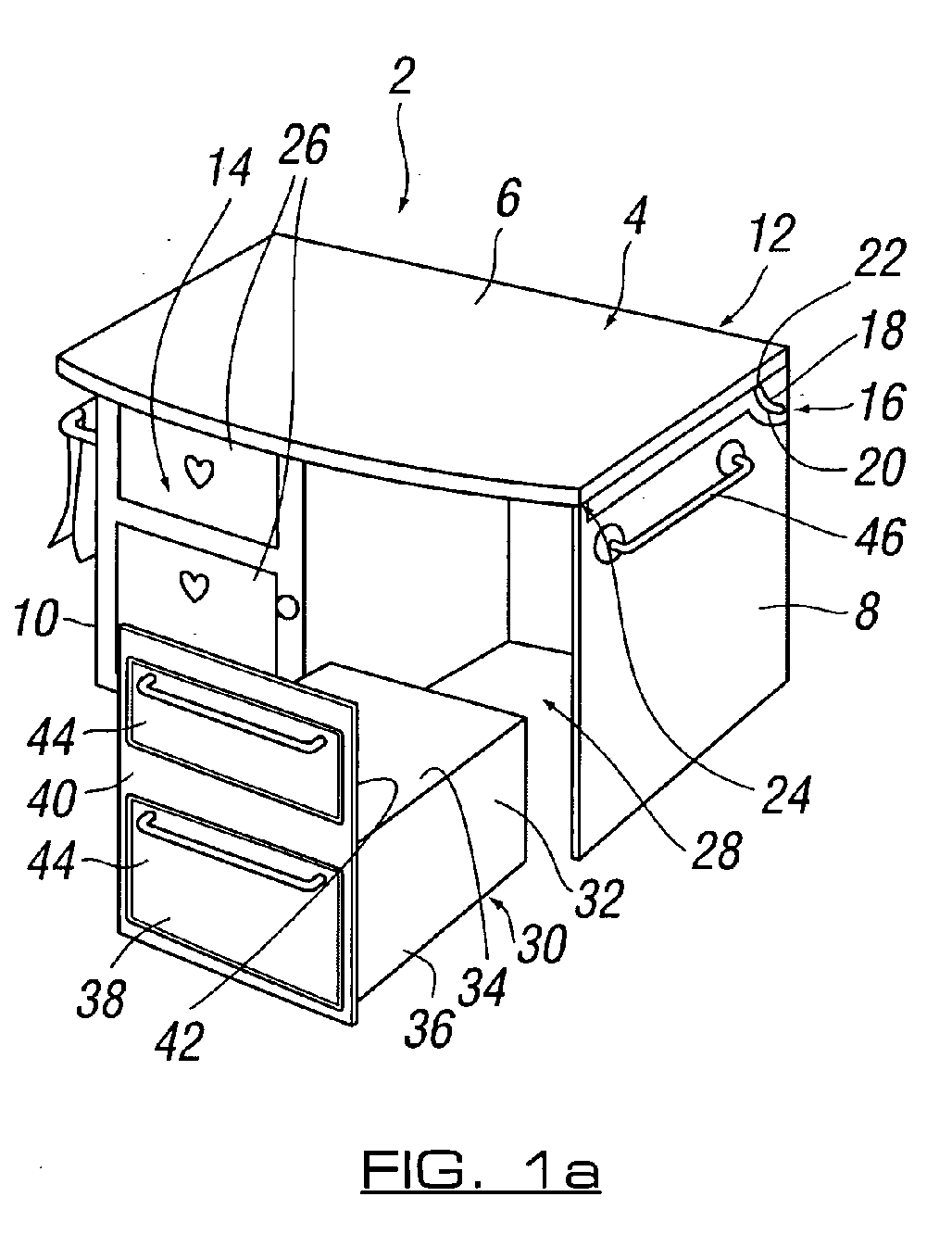
- a furniture unit in the form of a desk 2 or desk like unit, such as a dressing table and/or the like.
- the desk is movable between first and second configurations, the configurations being different to allow different working uses of the furniture unit in each of the configurations.
- the desk 2 comprises a first part or member 4, the upper surface 6 of which forms a worksurface of the desk.
- the desk 2 further includes end walls 8, 10, a rear wall 12 and a front wall 14.
- the first member 4 is pivotably mounted to end walls 8, 10 via a pivot arrangement 16. More particularly, pivot arrangement 16 includes a plate portion 18 with a curved slot 20 defined therein. A pin or protruding portion 22 provided on end walls 8, 10 is movably mounted in slot 20.
- first member 4 is pivotably movable between the first configuration shown in figures 1a , 2a and 3a , wherein member 4 is substantially horizontally and located substantially perpendicular to end walls 8, 10, to a second configuration shown in figures 1b , 2b , and 3b , wherein member 4 is substantially perpendicular to a second part or member 24 and substantially parallel to rear wall 12, as will be described in more detail below.
- Front wall 14 has a plurality of drawers 26 defined on one side thereof. Each drawer 26 is movable between closed and open positions. A recess 28 is defined adjacent drawers 26. The recess is defined between rear wall 12, end wall 8 and interior wall 28 of drawers 26.
- a seat 30 is provided with desk 2.
- Seat 30 includes a seating portion 32 having an upper seating surface 34, and side walls 36.
- a front wall 38 of seat 30 has an outer wall 40 and an inner wall 42. At least part of an upper section of inner wall 42 forms a back to seat 30.
- Drawers 44 are defined in outer wall 40 of front wall 38.
- the drawers 44 can be mock drawers for aesthetic appearance only, as is the case with uppermost draw 44, or can be movable between open and closed positions, as is the case with lower most draw 44.
- Drawers 44 and 26 can be slidably movable, pivotably movable and/or the like between said open and closed positions.
- One or more accessories can be provided on the outer surface of end walls 8, 10. These accessories can be in the form of a towel rail 46, as shown in figures 1a and 1b , storage compartments 48, as shown in figures 2a and 2b and/or the like.
- first member 4 is located on top of second member 24, such that lower surface 50 of first member 4 and upper surface 52 of second member 24 are in abutting relationship. Furthermore, first and second members 4, 24 are substantially horizontal and parallel to each other. Both of said first and second members are substantially planar in form. First member 4 is pivotably moved via pivot arrangement 16 in an upwardly direction to move the furniture unit from the first configuration to the second configuration shown in figures 1b , 2b and 3b . In the second configuration, first member 4 is substantially perpendicular to second member 24. As such, upper surface 52 of second member 24 now forms the worksurface of the furniture unit and the lower surface 50 of first member 4 forms a back or rear surface to the furniture unit.
- the desk configuration is converted into a different toy play area or a different play configuration, such as a kitchen, tool workshop, beauty parlour and/or the like.
- a plurality of items in the form of kitchen appliances are defined in or on upper surface 52 of second member 24 and/or lower surface 50 of first member 4. These items can be printed, painted and/or the like onto said surfaces 50, 52. Items in the form of kitchen utensils 54 can be detachably attached to surfaces 50, 52 to increase the realism of the kitchen configuration to a child and to maintain the utensils in place on movement of the first member relative to the second member.
- a recess 58 is defined in upper surface 52 to form a sink and items in the form of taps 56 are movable between a substantially folded condition in the first configuration, wherein taps 56 are located in recess 58 and a substantially horizontal, to a substantially erect condition in the second configuration, wherein taps 56 are substantially vertical.
- seat 30 is typically moved into recess 28 to close said recess and to form a substantially continuous front surface 14 to said second configuration furniture unit.
- front wall 38 of seat 30 forms part of front wall 14 of the furniture unit.
- items in the form of beauty utensils such as a brush, comb, hairdryer and/or the like can be provided with the unit.
- a furniture unit movable between at least first and second configurations provides the unit with a greater number of applications, particularly when the furniture unit is in the form of toy apparatus.
Landscapes
- Combinations Of Kitchen Furniture (AREA)
Abstract
There is provided a furniture unit (2) for allowing at least a first part (4) of said furniture unit (2) to move relative to at least a second part (24) of said furniture unit (2) between at least first and second working configurations. The furniture unit (2) and/or said at least first and/or second furniture unit parts have a different use or application in each of said first and second working configurations.
Description
- This invention relates to a furniture unit and method of use thereof.
- Although the following description refers almost exclusively to a furniture unit in the form of toy apparatus suitable for use by a child, it will be appreciated by persons skilled in the art that the present invention can be any type of furniture unit and can be used for any suitable purpose or purposes by any user.
- Furniture units generally have a single configuration in which they are used. Furniture units are known in which one or more members thereof can be moved between folded and expanded conditions, such as movable leaves of a table to allow the size of the table to be increased or decreased. However, the application of use of the furniture unit remains the same.
- It is an aim of the present invention to provide an improved furniture unit which is movable between at least two different configurations and, in said configurations, the application of use of the unit is different.
- It is an aim of the present invention to provide a method of use of a furniture unit.
- According to a first aspect of the present invention there is provided a furniture unit, said furniture unit provided with means for allowing at least a first part of said furniture unit to move relative to at least a second part of said furniture unit between at least first and second working configurations, the furniture unit and/or said at least first and/or second furniture unit parts having a different use or application in each of said first and second working configurations.
- Thus, the furniture unit has at least two different working configurations, thereby maximising the use of the furniture unit whilst reducing the space taken up by the furniture unit compared to prior art furniture units which require two separate furniture units; one furniture unit for each working configuration.
- The term "working configuration" is intended to cover the furniture unit being of use or application in that configuration rather than simply being a storage configuration where it has no use.
- Preferably the at least first part is moved to a position substantially perpendicular or at an inclined angle relative to the at least second part in the second working configuration and/or the position in which the at least first part took in the first working configuration.
- In one embodiment the inclined angle is less than 180 degrees or greater than 180 degrees but not equal to 180 degrees (i.e. the first part is not moved to a similar position or plane in the first and second configurations).
- Preferably the at least first part is provided over, adjacent to, in abutting relationship with, over, on top of and/or at least partially overlapping said at least second part in the first working configuration.
- Preferably the at least first part forms a work surface of the furniture unit in the first configuration. Further preferably an upper surface of the first part forms the worksurface.
- Preferably the at least second part forms a worksurface of the furniture unit in the second configuration. Further preferably an upper surface of the second part forms the worksurface. In one embodiment the upper surface of the second part has no use or is not accessible as a worksurface in the first working configuration.
- Yet further preferably the lower surface of the at least first part and the upper surface of the at least second part are substantially parallel and adjacent and/or in abutting relationship in said first working configuration. The first part can be moved a spaced distance apart from the second part in the second working configuration and/or vice versa.
- Preferably the at least first part is substantially planar, flat or sheet like in form.
- A portion or substantially the entire first and/or second parts can form a worksurface in the first and/or second configurations.
- Preferably the at least first and second parts are substantially horizontally arranged when in the first working configuration.
- In one embodiment the at least first part is pivotably mounted to said furniture unit and/or said at least second part, thereby allowing the first part to be pivotably moved between said first and second working configurations. Preferably one or more hinges or pivots are provided to allow this pivotable movement.
- However, the at least first part can be pivotably, rotatably and/or slidably movable with respect to the at least second part and/or furniture unit.
- Preferably guide means are provided for guiding the movement of the at least first part relative to the at least second part and/or said furniture unit.
- In one embodiment the guide means includes a pin or protruding arm provided on one of said at least first or second parts which is slidably movable in a slot or channel provided on the other of said at least first or second parts.
- Preferably the slot or channel is substantially arcuate or curved in shape.
- In one embodiment a lower surface of the at least first part forms a wall, and preferably an upright wall of the furniture unit in the second working configuration.
- Preferably one or more items can be provided between the at least first and second part in the first working configuration. In one example, the items can be substantially inaccessible in the first working configuration and accessible in the second working configuration. The items can be associated with the use or application of the furniture unit in the second working configuration. The one or more items are preferably attached or detachably attached to the first and/or second parts in the first and/or second working configurations.
- In one embodiment one or more items are provided between the at least first and second parts and said items are movable between a substantially or partially flattened, folded and/or collapsed position with the furniture unit in the first working configuration, to a substantially erect position when the furniture unit is in the second working configuration.
- Preferably the one or more items move between the substantially flattened, folded and/or collapsed position and the erect position on movement of the at least first part relative to the at least second part.
- In one embodiment securing means are provided to maintain the furniture unit in the first and/or second working configurations.
- The securing means can include any or any combination of one or more locks, bolts, ties, clips, hook & loop fastenings, screws, nuts and bolts, inter-engaging members and/or the like.
- In one embodiment the furniture unit and/or at least second part has one or more cavities, apertures or recesses defined therein.
- Preferably the at least first part is slidably movable relative to said cavity, recess or aperture between said first and second working configurations.
- Preferably the at least first part is a spaced distance apart from said cavity, recess or aperture in said first working configuration and is substantially or partially recessed within said cavity, recess or aperture in said second working configuration.
- Preferably the at least first part is in the form of a seat or chair or has a seating portion associated therewith, thereby allowing the at least first part to act as a seat in the first working configuration.
- Preferably one or more drawers, compartments and/or cupboards are defined in said at least first part and, with the at least first part in the second working configuration, the one or more drawers, compartments and/or compartments are used as part of the furniture unit and/or at least second part. It will be noted that the one or more drawers, compartments and/or compartments could also be used in the first configuration as well if required. Thus, in one embodiment, the at least first part is arranged such that in the first configuration it is the form of or can be used as a seat or chair and in the second configuration it is in the form of a set of drawers, cupboards and/or the like.
- Preferably the cavity, aperture or recess is adjacent a lower edge or base of the furniture unit and/or at least second part.
- Preferably the at least first part is in the form of a chair or seat having a seating portion, preferably on or adjacent an upper surface thereof, a base portion and one or more side walls. Preferably the one or more side walls includes or is in the form of one or more drawers, compartments, cupboards and/or the like.
- A surface of the at least first part in which the drawer, cupboard and/or compartment are formed is preferably located substantially flush with a surface or second part of the furniture unit in the second working configuration. One or more further drawers, cupboards and/or compartments can be defined in said surface or second part of the furniture unit.
- In one embodiment one or more cavities or recesses are defined in the at least second part, the openings to said cavities or recesses defined in an upper surface of the at least second part. In this embodiment, one or more of the cavities or recesses are accessible when the furniture unit is in the second working configuration. For example, the one or more cavities can be in the form of a kitchen sink and/or the like.
- In one embodiment the furniture unit is in the form of a desk in the first working configuration. Further preferably it is in the form of a work unit, such as a kitchen unit, in the second working configuration.
- In the first working configuration the furniture unit typically includes a substantially horizontal worksurface and one or more side walls depending downwardly from said worksurface. Preferably one or more drawers are defined in or associated with one or more of the side walls. The one or more drawers are provided below the level of the worksurface.
- In the second working configuration the furniture unit typically includes a substantially horizontal worksurface with a substantially vertical rear wall extending above the worksurface and one or more side walls depending downwardly from said worksurface. Preferably one or more drawers are defined in or associated with one or more of the side walls. The one or more drawers are provided below the level of the worksurface.
- According to an aspect of the present invention there is provided a furniture unit, said furniture unit including a first member and at least a second member, the first member forming a worksurface of said furniture unit when said furniture unit is in a first configuration, and wherein said first member is movable relative to said at least second member to form a second configuration of said furniture unit, the second member forming a worksurface of said furniture unit in said second configuration.
- According to a further aspect of the present invention there is provided a furniture unit, said furniture unit movable between a first configuration in the form of a desk to a second different configuration.
- Preferably the second different configuration is in the form of a work unit, such as kitchen unit and/or the like.
- According to a further aspect of the present invention there is provided toy apparatus in the form of a furniture unit.
- According to a yet further aspect of the present invention there is provided a furniture unit, said furniture unit including first and second members and one or more items located between said first and second members, said one or more items movable between a substantially or partially flattened, folded and/or collapsed position and a substantially erect condition on relative movement of said first and/or said second members.
- According to a yet further aspect of the present invention there is provided a method of using a furniture unit, said method including the steps of moving at least a first part of said furniture unit relative to at least a second part of said furniture unit between at least first and second working configurations, the furniture unit and/or said at least first and/or second furniture unit parts having a different use or application in each of said first and second working configurations.
- Embodiments of the present invention will now be illustrated with reference to the accompanying figures, wherein:
-
Figures 1a and 1b illustrate a furniture unit in a first configuration in the form of a desk and a second configuration in the form of a kitchen unit; -
Figures 2a and 2b illustrate a furniture unit in a first configuration in the form of a desk and a second configuration in the form of a tool workshop; and -
Figures 3a and 3b illustrate a furniture unit in a first configuration in the form of a desk or dressing table and a second configuration in the form of a beauty salon. - Referring to
figures 1a ,2a and3a , there is illustrated a furniture unit in the form of adesk 2 or desk like unit, such as a dressing table and/or the like. The desk is movable between first and second configurations, the configurations being different to allow different working uses of the furniture unit in each of the configurations. - In the first configuration, the
desk 2 comprises a first part ormember 4, theupper surface 6 of which forms a worksurface of the desk. Thedesk 2 further includesend walls rear wall 12 and afront wall 14. - The
first member 4 is pivotably mounted to endwalls pivot arrangement 16. More particularly,pivot arrangement 16 includes aplate portion 18 with acurved slot 20 defined therein. A pin or protrudingportion 22 provided onend walls slot 20. Thus,first member 4 is pivotably movable between the first configuration shown infigures 1a ,2a and3a , whereinmember 4 is substantially horizontally and located substantially perpendicular to endwalls figures 1b ,2b , and3b , whereinmember 4 is substantially perpendicular to a second part ormember 24 and substantially parallel torear wall 12, as will be described in more detail below. -
Front wall 14 has a plurality ofdrawers 26 defined on one side thereof. Eachdrawer 26 is movable between closed and open positions. Arecess 28 is definedadjacent drawers 26. The recess is defined betweenrear wall 12,end wall 8 andinterior wall 28 ofdrawers 26. - A
seat 30 is provided withdesk 2.Seat 30 includes aseating portion 32 having anupper seating surface 34, andside walls 36. Afront wall 38 ofseat 30 has anouter wall 40 and aninner wall 42. At least part of an upper section ofinner wall 42 forms a back toseat 30.Drawers 44 are defined inouter wall 40 offront wall 38. Thedrawers 44 can be mock drawers for aesthetic appearance only, as is the case withuppermost draw 44, or can be movable between open and closed positions, as is the case with lowermost draw 44.Drawers - One or more accessories can be provided on the outer surface of
end walls towel rail 46, as shown infigures 1a and 1b , storage compartments 48, as shown infigures 2a and 2b and/or the like. - In the first configuration,
first member 4 is located on top ofsecond member 24, such thatlower surface 50 offirst member 4 andupper surface 52 ofsecond member 24 are in abutting relationship. Furthermore, first andsecond members First member 4 is pivotably moved viapivot arrangement 16 in an upwardly direction to move the furniture unit from the first configuration to the second configuration shown infigures 1b ,2b and3b . In the second configuration,first member 4 is substantially perpendicular tosecond member 24. As such,upper surface 52 ofsecond member 24 now forms the worksurface of the furniture unit and thelower surface 50 offirst member 4 forms a back or rear surface to the furniture unit. - With the furniture unit in the second configuration, it can be used for different applications compared to when in the first configuration. Thus, in the illustrated examples, the desk configuration is converted into a different toy play area or a different play configuration, such as a kitchen, tool workshop, beauty parlour and/or the like.
- In
figures 1b , a plurality of items in the form of kitchen appliances are defined in or onupper surface 52 ofsecond member 24 and/orlower surface 50 offirst member 4. These items can be printed, painted and/or the like onto saidsurfaces kitchen utensils 54 can be detachably attached tosurfaces recess 58 is defined inupper surface 52 to form a sink and items in the form oftaps 56 are movable between a substantially folded condition in the first configuration, wherein taps 56 are located inrecess 58 and a substantially horizontal, to a substantially erect condition in the second configuration, wherein taps 56 are substantially vertical. - In the second configuration,
seat 30 is typically moved intorecess 28 to close said recess and to form a substantially continuousfront surface 14 to said second configuration furniture unit. Thus,front wall 38 ofseat 30 forms part offront wall 14 of the furniture unit. - In
figures 2a and 2b , there is norear wall 12 definingrecess 28. In addition, items in the form oftools 54 are detachably attached tolower surface 50. - In
figures 3a and 3b , items in the form of beauty utensils, such as a brush, comb, hairdryer and/or the like can be provided with the unit. - Thus, it can be seen that the provision of a furniture unit movable between at least first and second configurations provides the unit with a greater number of applications, particularly when the furniture unit is in the form of toy apparatus.
Claims (28)
- A furniture unit, said furniture unit provided with means for allowing at least a first part of said furniture unit to move relative to at least a second part of said furniture unit between at least first and second working configurations, the furniture unit and/or said at least first and/or second furniture unit parts having a different use or application in each of said first and second working configurations.
- A furniture unit according to claim 1 wherein the at least first part forms a worksurface of said furniture unit in said first working configuration.
- A furniture unit according to claim 1 wherein the at least first part is moved to a position substantially perpendicular or at an inclined angle relative to the at least second part when moved between said first and second working configurations.
- A furniture unit according to claim 1 wherein the at least second part of said furniture unit forms a worksurface in said second working configuration.
- A furniture unit according to claim 1 wherein the at least first part is movably mounted to said furniture unit and/or said at least second part to allow said first part to be moved between said first and second working configurations.
- A furniture unit according to claim 5 wherein guide means are provided for guiding said movement.
- A furniture unit according to claim 5 wherein the at least first part is pivotably mounted to said furniture unit and/or said at least second part to allow said first part to be moved between said first and second working configurations.
- A furniture unit according to claim 7 wherein guide means for guiding the pivotable movement includes a pin or protruding arm provided on one of said at least first or second parts which is slidably movable in a slot or channel provided on the other of said at least first or second parts.
- A furniture unit according to claim 8 wherein the slot or channel is substantially arcuate or curved in shape.
- A furniture unit according to claim 1 wherein a recess or aperture is defined in an upper surface of said at least second part.
- A furniture unit according to claim 10 wherein the recess or aperture is in the form of a kitchen sink and the furniture unit is in the form of a kitchen unit in said second working configuration.
- A furniture unit according to claim 1 wherein the at least first part is slidably movable relative to said furniture unit and/or said at least second part.
- A furniture unit according to claim 1 wherein a recess or aperture is defined in said furniture unit and/or said at least second part and said at least first part is a spaced distance apart from said recess or aperture in said first working configuration and is located substantially within said recess or aperture in said second working configuration.
- A furniture unit according to claim 13 wherein the at least first part forms a seat in the first configuration, and said first part forms a drawer, cupboard and/or compartment in the second configuration.
- A furniture unit according to claim 14 wherein a surface of the at least first part in which the drawer, cupboard and/or compartment are formed is located substantially flush with a surface or second part of the furniture unit in the second working configuration.
- A furniture unit according to claim 1 wherein the at least first part is provided adjacent to, over and/or at least partially overlapping said at least second part in said first configuration.
- A furniture unit according to claim 16 wherein the at least first part is moved a spaced distance apart from said second part in said second configuration.
- A furniture unit according to claim 1 wherein an upper surface of the at least first part forms a worksurface and the lower surface of the first member is adjacent to and substantially parallel to an upper surface of the at least second part in the first working configuration; and the upper surface of the at least first part is substantially perpendicular to or at an acute angle to the upper surface of the at least second part in the second working configuration.
- A furniture unit according to claim 1 wherein one or more items are provided between the at least first and second parts in the first working configuration.
- A furniture unit according to claim 19 wherein the one or more items are substantially inaccessible in the first working configuration and, in the second working configuration, the one or more items become accessible.
- A furniture unit according to claim 19 wherein the one or more items are movable between a substantially or partially flattened, folded and/or collapsed position in the first working configuration and a substantially erect condition in the second working configuration.
- A furniture unit according to claim 19 wherein the one or more items are attached or detachably attached to the unit in the first and/or second working configurations.
- A furniture unit according to claim 1 wherein securing means are provided to maintain the furniture unit in the first and/or second working configurations.
- A furniture unit according to claim 23 wherein the securing means includes any or any combination of one or more locks, bolts, ties, clips, hook and loop fastenings, screws, nuts and bolts or inter-engaging members.
- A furniture unit according to claim 1 wherein one or more drawers, cupboards and/or compartments are defined in the furniture unit.
- A furniture unit according to claim 1 wherein said unit forms a different toy arrangement in said first and second working configurations.
- A furniture unit according to claim 1 wherein printed or painted matter is provided on an outer surface of said furniture unit in said first and/or second working configurations to increase the realism of the same to a user.
- A method of using a furniture unit, said method including the steps of moving at least a first part of said furniture unit relative to at least a second part of said furniture unit between at least first and second working configurations, the furniture unit and/or said at least first and/or second furniture unit parts having a different use or application in each of said first and second working configurations.
Applications Claiming Priority (1)
| Application Number | Priority Date | Filing Date | Title |
|---|---|---|---|
| GBGB0700062.3A GB0700062D0 (en) | 2007-01-03 | 2007-01-03 | Furniture unit |
Publications (1)
| Publication Number | Publication Date |
|---|---|
| EP1941937A1 true EP1941937A1 (en) | 2008-07-09 |
Family
ID=37759208
Family Applications (1)
| Application Number | Title | Priority Date | Filing Date |
|---|---|---|---|
| EP07254900A Withdrawn EP1941937A1 (en) | 2007-01-03 | 2007-12-17 | Furniture unit |
Country Status (2)
| Country | Link |
|---|---|
| EP (1) | EP1941937A1 (en) |
| GB (2) | GB0700062D0 (en) |
Cited By (1)
| Publication number | Priority date | Publication date | Assignee | Title |
|---|---|---|---|---|
| US8568194B2 (en) | 2011-03-01 | 2013-10-29 | Guidecraft Inc. | Collapsible toy kitchen apparatuses and methods |
Citations (4)
| Publication number | Priority date | Publication date | Assignee | Title |
|---|---|---|---|---|
| US2348573A (en) * | 1941-11-14 | 1944-05-09 | Rogers Yubie William | Combination table |
| US2604373A (en) * | 1949-02-18 | 1952-07-22 | William P Beriou | Convertible table and bar |
| DE9401833U1 (en) * | 1994-02-04 | 1994-10-13 | Elbe-Werkstätten GmbH, 21077 Hamburg | Children's furniture program |
| WO2004060115A1 (en) * | 2002-12-17 | 2004-07-22 | Mattel, Inc. | Convertible toy chair and vanity combination |
Family Cites Families (6)
| Publication number | Priority date | Publication date | Assignee | Title |
|---|---|---|---|---|
| US2646330A (en) * | 1951-04-20 | 1953-07-21 | James A Swainbank | Combination workbench and drawing table |
| US4501457A (en) * | 1982-12-17 | 1985-02-26 | Pond Murray C | Kitchen table for camper |
| KR910001943B1 (en) * | 1988-04-15 | 1991-03-30 | 이해섭 | Folding sink |
| US6039416A (en) * | 1999-03-08 | 2000-03-21 | Lambert; Jeffrey W. | Wall mounted pivoting work bench |
| GB0012000D0 (en) * | 2000-05-19 | 2000-07-05 | Brown Robert | Dual table for working from home |
| US20050145148A1 (en) * | 2004-01-05 | 2005-07-07 | Mason Yeung Kai W. | Desk with removable multiple position and sided writing surface |
-
2007
- 2007-01-03 GB GBGB0700062.3A patent/GB0700062D0/en not_active Ceased
- 2007-12-17 EP EP07254900A patent/EP1941937A1/en not_active Withdrawn
- 2007-12-17 GB GB0724521A patent/GB2445452A/en not_active Withdrawn
Patent Citations (4)
| Publication number | Priority date | Publication date | Assignee | Title |
|---|---|---|---|---|
| US2348573A (en) * | 1941-11-14 | 1944-05-09 | Rogers Yubie William | Combination table |
| US2604373A (en) * | 1949-02-18 | 1952-07-22 | William P Beriou | Convertible table and bar |
| DE9401833U1 (en) * | 1994-02-04 | 1994-10-13 | Elbe-Werkstätten GmbH, 21077 Hamburg | Children's furniture program |
| WO2004060115A1 (en) * | 2002-12-17 | 2004-07-22 | Mattel, Inc. | Convertible toy chair and vanity combination |
Cited By (1)
| Publication number | Priority date | Publication date | Assignee | Title |
|---|---|---|---|---|
| US8568194B2 (en) | 2011-03-01 | 2013-10-29 | Guidecraft Inc. | Collapsible toy kitchen apparatuses and methods |
Also Published As
| Publication number | Publication date |
|---|---|
| GB0700062D0 (en) | 2007-02-07 |
| GB0724521D0 (en) | 2008-01-30 |
| GB2445452A (en) | 2008-07-09 |
Similar Documents
| Publication | Publication Date | Title |
|---|---|---|
| JP6158215B2 (en) | Cabinet and mirror selectively attached to a hinge that supports the door of the room to the door frame, hinge for such attachment, and method for its attachment | |
| US8113608B2 (en) | Cabinets and mirrors selectively mounted on hinges supporting room doors on door frames, hinges for such mountings, and methods for so mounting | |
| US5558418A (en) | Furniture assembly for a compact desk | |
| US5536080A (en) | Free standing work station | |
| US20220218104A1 (en) | Storage system | |
| US20140327350A1 (en) | Cabinets and mirrors selectively mounted on hinges supporting roomdoors on door frames, hinges for such mountings, and methods for so mounting | |
| US20080284292A1 (en) | Deployable workstation | |
| US20070159035A1 (en) | Wall desk | |
| US11503910B1 (en) | Modular organizer system | |
| US20050279257A1 (en) | Wiring and Accessory Management Furniture | |
| US20100237756A1 (en) | Pedestal vanity | |
| JP6787805B2 (en) | Storage device and installation method of storage device | |
| EP1941937A1 (en) | Furniture unit | |
| US5584548A (en) | Office armoire | |
| JP2004049565A (en) | Island kitchen | |
| EP3151702A1 (en) | Cabinets and mirrors selectively mounted on hinges supporting roomdoors on door frames, hinges for such mountings, and methods for so mounting | |
| US20200196752A1 (en) | Convertible Article Of Furniture | |
| CN213734400U (en) | A multifunctional toolbox for graphic art design | |
| US6126252A (en) | Workstation incorporating Pivoting and Sliding Drawer | |
| KR200461975Y1 (en) | Furniture comprising sliding storage case | |
| US12396555B2 (en) | Vanity fold-out organizer | |
| CN213720811U (en) | Console mode corner cabinet structure of kitchen cabinet | |
| KR200411326Y1 (en) | Desk cabinet with adjustable desk board | |
| JPH0511764Y2 (en) | ||
| KR20110003771U (en) | Table |
Legal Events
| Date | Code | Title | Description |
|---|---|---|---|
| PUAI | Public reference made under article 153(3) epc to a published international application that has entered the european phase |
Free format text: ORIGINAL CODE: 0009012 |
|
| AK | Designated contracting states |
Kind code of ref document: A1 Designated state(s): AT BE BG CH CY CZ DE DK EE ES FI FR GB GR HU IE IS IT LI LT LU LV MC MT NL PL PT RO SE SI SK TR |
|
| AX | Request for extension of the european patent |
Extension state: AL BA HR MK RS |
|
| AKX | Designation fees paid |
Designated state(s): AT BE BG CH CY CZ DE DK EE ES FI FR GB GR HU IE IS IT LI LT LU LV MC MT NL PL PT RO SE SI SK TR |
|
| STAA | Information on the status of an ep patent application or granted ep patent |
Free format text: STATUS: THE APPLICATION IS DEEMED TO BE WITHDRAWN |
|
| 18D | Application deemed to be withdrawn |
Effective date: 20090110 |