EP1939599A2 - Pressure transducer diaphragm and method of making same - Google Patents
Pressure transducer diaphragm and method of making same Download PDFInfo
- Publication number
- EP1939599A2 EP1939599A2 EP07123556A EP07123556A EP1939599A2 EP 1939599 A2 EP1939599 A2 EP 1939599A2 EP 07123556 A EP07123556 A EP 07123556A EP 07123556 A EP07123556 A EP 07123556A EP 1939599 A2 EP1939599 A2 EP 1939599A2
- Authority
- EP
- European Patent Office
- Prior art keywords
- substrate
- trench
- etching
- diaphragm
- pressure transducer
- Prior art date
- Legal status (The legal status is an assumption and is not a legal conclusion. Google has not performed a legal analysis and makes no representation as to the accuracy of the status listed.)
- Withdrawn
Links
- 238000004519 manufacturing process Methods 0.000 title claims abstract description 9
- 239000000758 substrate Substances 0.000 claims abstract description 34
- 239000012528 membrane Substances 0.000 claims abstract description 17
- 238000000034 method Methods 0.000 claims description 31
- 238000005530 etching Methods 0.000 claims description 19
- XUIMIQQOPSSXEZ-UHFFFAOYSA-N Silicon Chemical compound [Si] XUIMIQQOPSSXEZ-UHFFFAOYSA-N 0.000 claims description 10
- 229910052710 silicon Inorganic materials 0.000 claims description 10
- 239000010703 silicon Substances 0.000 claims description 10
- 239000000463 material Substances 0.000 claims description 8
- 238000001039 wet etching Methods 0.000 claims description 8
- 238000001312 dry etching Methods 0.000 claims description 7
- 238000009877 rendering Methods 0.000 claims description 7
- 230000004927 fusion Effects 0.000 claims description 4
- 229910021420 polycrystalline silicon Inorganic materials 0.000 claims description 3
- 229920005591 polysilicon Polymers 0.000 claims description 3
- 238000009792 diffusion process Methods 0.000 description 7
- 239000007787 solid Substances 0.000 description 6
- VYPSYNLAJGMNEJ-UHFFFAOYSA-N Silicium dioxide Chemical compound O=[Si]=O VYPSYNLAJGMNEJ-UHFFFAOYSA-N 0.000 description 2
- 239000012141 concentrate Substances 0.000 description 2
- 238000000708 deep reactive-ion etching Methods 0.000 description 2
- BHEPBYXIRTUNPN-UHFFFAOYSA-N hydridophosphorus(.) (triplet) Chemical compound [PH] BHEPBYXIRTUNPN-UHFFFAOYSA-N 0.000 description 2
- 230000035945 sensitivity Effects 0.000 description 2
- RZVAJINKPMORJF-UHFFFAOYSA-N Acetaminophen Chemical compound CC(=O)NC1=CC=C(O)C=C1 RZVAJINKPMORJF-UHFFFAOYSA-N 0.000 description 1
- ZOXJGFHDIHLPTG-UHFFFAOYSA-N Boron Chemical compound [B] ZOXJGFHDIHLPTG-UHFFFAOYSA-N 0.000 description 1
- 238000010420 art technique Methods 0.000 description 1
- 238000005452 bending Methods 0.000 description 1
- 229910052796 boron Inorganic materials 0.000 description 1
- 238000010276 construction Methods 0.000 description 1
- 239000003989 dielectric material Substances 0.000 description 1
- 238000005516 engineering process Methods 0.000 description 1
- 230000007717 exclusion Effects 0.000 description 1
- 239000011521 glass Substances 0.000 description 1
- 238000001802 infusion Methods 0.000 description 1
- 230000000873 masking effect Effects 0.000 description 1
- 229910052751 metal Inorganic materials 0.000 description 1
- 239000002184 metal Substances 0.000 description 1
- 150000002739 metals Chemical class 0.000 description 1
- 239000005297 pyrex Substances 0.000 description 1
- 235000012239 silicon dioxide Nutrition 0.000 description 1
- 239000000377 silicon dioxide Substances 0.000 description 1
Images


Classifications
-
- G—PHYSICS
- G01—MEASURING; TESTING
- G01L—MEASURING FORCE, STRESS, TORQUE, WORK, MECHANICAL POWER, MECHANICAL EFFICIENCY, OR FLUID PRESSURE
- G01L9/00—Measuring steady of quasi-steady pressure of fluid or fluent solid material by electric or magnetic pressure-sensitive elements; Transmitting or indicating the displacement of mechanical pressure-sensitive elements, used to measure the steady or quasi-steady pressure of a fluid or fluent solid material, by electric or magnetic means
- G01L9/0041—Transmitting or indicating the displacement of flexible diaphragms
- G01L9/0042—Constructional details associated with semiconductive diaphragm sensors, e.g. etching, or constructional details of non-semiconductive diaphragms
-
- H—ELECTRICITY
- H10—SEMICONDUCTOR DEVICES; ELECTRIC SOLID-STATE DEVICES NOT OTHERWISE PROVIDED FOR
- H10D—INORGANIC ELECTRIC SEMICONDUCTOR DEVICES
- H10D48/00—Individual devices not covered by groups H10D1/00 - H10D44/00
- H10D48/50—Devices controlled by mechanical forces, e.g. pressure
-
- B—PERFORMING OPERATIONS; TRANSPORTING
- B81—MICROSTRUCTURAL TECHNOLOGY
- B81B—MICROSTRUCTURAL DEVICES OR SYSTEMS, e.g. MICROMECHANICAL DEVICES
- B81B3/00—Devices comprising flexible or deformable elements, e.g. comprising elastic tongues or membranes
- B81B3/0064—Constitution or structural means for improving or controlling the physical properties of a device
- B81B3/0067—Mechanical properties
- B81B3/007—For controlling stiffness, e.g. ribs
Definitions
- This subject invention relates generally to pressure transducers.
- Microelectromechanical pressure sensors typically include a diaphragm or membrane supported by a frame. It is known to fabricate the diaphragm to include thinner and thicker areas called bosses. See U.S. Patent No. 6,140,143 incorporated herein by this reference. The thicker boss areas concentrate the stress created by deflection of the diaphragm. The bosses may be used to concentrate bending stresses in stress sensing piezoresistors or capacitive elements. The bosses can also be used to produce a sensing capacitance or an electrostatic drive gap by fabricating close adjacent structure.
- bosses are solid structures created by diffusion of material into a substrate at different depths and then etching the substrate. See Patent No. 6,140,143 referenced above.
- Prior bosses have a significant mass which, in the case of low pressure sensors, can result in orientation sensitivity.
- the thickness of the boss is also limited to the depth at which material can be infused into the substrate. In general, deeper infusions involve an added expense and increased time. Also, the width of the resulting boss structure increases because diffusion occurs both vertically and laterally in the substrate.
- the present invention provides a new method of making a pressure transducer diaphragm.
- the method can result in bosses with less mass.
- the resulting bosses are preferably hollow.
- the method results in higher stiffness bosses.
- the resulting bosses can be created using lower cost processing techniques.
- the bosses are lighter than solid structures of equal stiffness.
- a pressure transducer with less g-sensitivity. Bosses of arbitrary width and stiffness can be produced. Provided is the ability to vary the configuration of the bosses as desired.
- a better method of producing a pressure transducer diaphragm without the limitations associated with diffusion and bulk etching includes etching a trench in a substrate to define a hollow boss lower in mass but also relatively stiff.
- One aspect of the present invention features a method of making a pressure transducer diaphragm.
- One or more trenches are formed (e.g., etched) in a first surface of a first substrate.
- the trench is then rendered etch resistant.
- a cavity is formed (e.g., etched) in a second opposite surface of the first substrate defining a diaphragm supported by a frame with one or more hollow bosses stiffening the membrane.
- the one or more trenches have angled side walls. In another example, the one or more trenches have a flat bottom.
- the trench can be rendered etch resistant by doping the trench, diffusing the trench, or adding an etch resistant material to the trench. Also, material can be added to the trench. For example, polysilicon or epitaxial silicon layers can be grown in the trench.
- a second substrate is bonded to the first surface of the first substrate.
- the second substrate can fusion bonded to the first surface of the first substrate.
- the cavity can be formed using dry or wet etching techniques.
- a pressure transducer diaphragm is made by etching one or more trenches in a first surface of a first substrate, rendering the trench and the first surface etch resistant, and etching a cavity in a second opposite surface of the first substrate defining a diaphragm supported by a frame with one or more hollow bosses stiffening the membrane.
- a pressure transducer diaphragm is made by etching one or more trenches in a first surface of a first substrate, rendering the trench etch resistant, bonding a second substrate to the first surface, and etching a cavity in a second opposite surface of the first substrate defining a diaphragm supported by a frame with one or more hollow bosses stiffening the membrane.
- Figs. 1-2 depict an example of a pressure transducer diaphragm or membrane 10 in accordance with an embodiment of the present invention.
- Diaphragm 10 is supported by frame 12 and includes hollow boss or mesa 14. Additional bosses may traverse diaphragm 10. Typically, there are a number of bosses but only one is shown in the figures here for clarity.
- Diaphragm 10 in one particular example is 2.4 mm square, and 5 microns thick.
- Boss 14, Fig. 3 has angled side walls 16a and 16b with a wall thickness of 5 microns.
- Boss 14 can be formed in different configurations, however, as shown in Fig. 4 where boss 14' is smaller and in Fig. 5 where boss 14" has a flat surface 20 and two angled side walls 22a and 22b.
- the hollow boss or bosses have less mass than solid bosses and yet provide high stiffness.
- the result is, in one example, a pressure transducer with less g-sensitivity.
- substrate 50 As shown in Figs. 6A-6G , substrate 50, Fig. 6A (typically a silicon wafer) is masked as shown at 52, Fig. 6B and trench 54 is etched, Fig. 6C . Dry or wet etching techniques can be used. Trench 54 and surface 63 of substrate 50 are then rendered etch resistant typically by implanting phosphorous as shown at 56 in Fig. 6D . The junction formed by the implanted phosphorous in conjunction with an electrochemical etch stop prevents etching of the implanted regions. See U.S. Patent No. 6,140,143 incorporated herein by this reference. The wafer is then turned over, Fig. 6E and masked as shown at 58. Then, this surface of the wafer is etched to produce cavity 60, membrane 10 supported by frame 12, and hollow boss 14.
- wafer 70, Fig. 7A is masked as shown at 72 in Fig. 7B and trench 74 is etched using dry or wet etching techniques.
- Trench 74 has angled side walls as shown.
- Trench 74 is then rendered etch resistant by doping the trench (with Boron, for example), or diffusing the trench using n-type diffusion and using an electrochemical etch stop as discussed above, or adding the etch resistant material to the trench such as etch resistant dielectrics or metals to create etch resistant side walls.
- Polysilicon or epitaxial silicon layers can be grown above the etch resistant layer if required to increase the thickness of the side walls of the resulting boss.
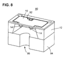
- the diaphragm is a component of MEMS pressure transducer 80, Fig. 8 .
- Two bosses 14 are shown here on diaphragm 10 (n-type) which also includes diffused piezoresistor 82.
- Frame 12 is P-type and resides on pyrex support 84 with port 86. The method of an embodiment of the present invention, however, is not limited to any specific pressure sensor design.
- the hollow boss technology of an embodiment of the present invention allows hollow shell-type features to be fabricated on thin diaphragms typically used in pressure sensors to provide areas of localized stiffness on an otherwise flexible membrane.
- the walls of the hollow boss structure are typically of a similar dimension to the membrane itself, however, there are hollow corrugated shape means renders them significantly stiffer.
- the etch stop for the trench can be a high doped P+ diffusion, a low doped n-type diffusion (for an electrochemical etch stop), or an etch resistant layer such as silicon dioxide.
- This technique also has the advantage of recreating a planar wafer surface for further wafer processing.
- the additional silicon layer can be bonded by either intermediate layers such as glass for electrostatic bonding or by silicon fusion bonding (also known as silicon direct bonding).
- Wet etching advantageously is able to produce a side wall at approximately 54.7° to the wafer surface. In this way, a minimum boss width of approximately 1.4 times the wafer thickness can be produced.
- a typical sensor wafer is 380 ⁇ m thick, this produces a 532 ⁇ m wide boss.
- Dry etching has the advantage of a vertical side wall etch. Narrow or arbitrary boss shapes are also possible.
- the resulting boss can be shallower than a solid boss, or have less mass, and yet be as stiff as the solid boss.
- Boss stiffness is not limited by diffusion depth of approximately 30 ⁇ m associated with prior art techniques. Hollow bosses of an embodiment of the present invention have a stiffness significantly higher than an equivalent amount of material creating a solid boss of equal surface shape and area. A narrow stiff boss can be created with conventional low cost processing techniques avoiding more expansive DRIE techniques if desired.
- the backside etch which forms the cavity in the final membrane structure could be any technique capable of creating the frame structure and etching down to the final membrane such as wet etching but DRIE etching might also be used with an oxide coated side wall.
- the technique of an embodiment of the present invention produces stiff boss structures smaller and less costly than other methods resulting in lighter and less g-sensitive boss structures.
- the boss structure had a wall thickness of 15 ⁇ m and a base 20 ⁇ m wide to 130 ⁇ m wide.
Landscapes
- Engineering & Computer Science (AREA)
- Chemical & Material Sciences (AREA)
- Analytical Chemistry (AREA)
- Physics & Mathematics (AREA)
- General Physics & Mathematics (AREA)
- Mechanical Engineering (AREA)
- Computer Hardware Design (AREA)
- Microelectronics & Electronic Packaging (AREA)
- Measuring Fluid Pressure (AREA)
- Pressure Sensors (AREA)
Abstract
Description
- This subject invention relates generally to pressure transducers.
- Microelectromechanical pressure sensors typically include a diaphragm or membrane supported by a frame. It is known to fabricate the diaphragm to include thinner and thicker areas called bosses. See
U.S. Patent No. 6,140,143 incorporated herein by this reference. The thicker boss areas concentrate the stress created by deflection of the diaphragm. The bosses may be used to concentrate bending stresses in stress sensing piezoresistors or capacitive elements. The bosses can also be used to produce a sensing capacitance or an electrostatic drive gap by fabricating close adjacent structure. - Typically, the bosses are solid structures created by diffusion of material into a substrate at different depths and then etching the substrate. See Patent No. 6,140,143 referenced above.
- Prior bosses have a significant mass which, in the case of low pressure sensors, can result in orientation sensitivity. The thickness of the boss is also limited to the depth at which material can be infused into the substrate. In general, deeper infusions involve an added expense and increased time. Also, the width of the resulting boss structure increases because diffusion occurs both vertically and laterally in the substrate.
- According to a first aspect, the present invention provides a new method of making a pressure transducer diaphragm. The method can result in bosses with less mass. The resulting bosses are preferably hollow. The method results in higher stiffness bosses. The resulting bosses can be created using lower cost processing techniques. The bosses are lighter than solid structures of equal stiffness. Provided is a pressure transducer with less g-sensitivity. Bosses of arbitrary width and stiffness can be produced. Provided is the ability to vary the configuration of the bosses as desired.
- Various aspects of the present invention result from the realization that a better method of producing a pressure transducer diaphragm without the limitations associated with diffusion and bulk etching includes etching a trench in a substrate to define a hollow boss lower in mass but also relatively stiff.
- Various aspects of the present invention, however, in other embodiments, need not achieve all these objectives and the claims hereof should not be limited to structures or methods capable of achieving these objectives.
- One aspect of the present invention features a method of making a pressure transducer diaphragm. One or more trenches are formed (e.g., etched) in a first surface of a first substrate. The trench is then rendered etch resistant. A cavity is formed (e.g., etched) in a second opposite surface of the first substrate defining a diaphragm supported by a frame with one or more hollow bosses stiffening the membrane.
- Dry etching or wet etching techniques can be used to form the trenches. In one example, the one or more trenches have angled side walls. In another example, the one or more trenches have a flat bottom.
- The trench can be rendered etch resistant by doping the trench, diffusing the trench, or adding an etch resistant material to the trench. Also, material can be added to the trench. For example, polysilicon or epitaxial silicon layers can be grown in the trench.
- In one example, a second substrate is bonded to the first surface of the first substrate. The second substrate can fusion bonded to the first surface of the first substrate. The cavity can be formed using dry or wet etching techniques.
- In one embodiment, a pressure transducer diaphragm is made by etching one or more trenches in a first surface of a first substrate, rendering the trench and the first surface etch resistant, and etching a cavity in a second opposite surface of the first substrate defining a diaphragm supported by a frame with one or more hollow bosses stiffening the membrane.
- In another embodiment, a pressure transducer diaphragm is made by etching one or more trenches in a first surface of a first substrate, rendering the trench etch resistant, bonding a second substrate to the first surface, and etching a cavity in a second opposite surface of the first substrate defining a diaphragm supported by a frame with one or more hollow bosses stiffening the membrane.
- Various objects, features and advantages of the present invention will occur to those skilled in the art from the following description of a preferred embodiment and the accompanying drawings, in which:
-
Fig. 1 is a schematic top view showing an example of a pressure transducer diaphragm in accordance with an embodiment of the present invention; -
Fig. 2 is a schematic three-dimensional isometric view of the pressure transducer diaphragm shown inFig. 1 ; -
Fig. 3 is a schematic cross-sectional view of a portion of the pressure transducer diaphragm shown inFig. 2 taken a long line 3-3 ofFig. 2 ; -
Fig. 4 is a schematic partial cross-sectional view showing a portion of another example of a pressure transducer diaphragm in accordance with an embodiment of the present invention; -
Fig. 5 is a schematic cross-sectional partial view of still another example of a pressure transducer diaphragm in accordance with an embodiment of the present invention; -
Figs. 6A-6G are highly schematic cross-sectional views depicting the primary steps associated with making a pressure transducer diaphragm in accordance with one embodiment of the present invention; -
Figs. 7A-7F are highly schematic cross-sectional views showing a primary steps associated with another method of making a pressure transducer diaphragm in accordance with an embodiment of the present invention; and -
Fig. 8 is a schematic three-dimensional cross-sectional view showing an example of a complete MEMS pressure transducer in accordance with an embodiment of the present invention. - Aside from the preferred embodiment or embodiments disclosed below, this invention is capable of other embodiments and of being practiced or being carried out in various ways. Thus, it is to be understood that the invention is not limited in its application to the details of construction and the arrangements of components set forth in the following description or illustrated in the drawings. If only one embodiment is described herein, the claims hereof are not to be limited to that embodiment. Moreover, the claims hereof are not to be read restrictively unless there is clear and convincing evidence manifesting a certain exclusion, restriction, or disclaimer.
-
Figs. 1-2 depict an example of a pressure transducer diaphragm ormembrane 10 in accordance with an embodiment of the present invention.Diaphragm 10 is supported byframe 12 and includes hollow boss ormesa 14. Additional bosses may traversediaphragm 10. Typically, there are a number of bosses but only one is shown in the figures here for clarity.Diaphragm 10 in one particular example is 2.4 mm square, and 5 microns thick. Boss 14,Fig. 3 has angled side walls 16a and 16b with a wall thickness of 5 microns. Boss 14 can be formed in different configurations, however, as shown inFig. 4 where boss 14' is smaller and inFig. 5 whereboss 14" has aflat surface 20 and twoangled side walls - In any configuration, the hollow boss or bosses have less mass than solid bosses and yet provide high stiffness. The result is, in one example, a pressure transducer with less g-sensitivity.
- As shown in
Figs. 6A-6G ,substrate 50,Fig. 6A (typically a silicon wafer) is masked as shown at 52,Fig. 6B andtrench 54 is etched,Fig. 6C . Dry or wet etching techniques can be used.Trench 54 andsurface 63 ofsubstrate 50 are then rendered etch resistant typically by implanting phosphorous as shown at 56 inFig. 6D . The junction formed by the implanted phosphorous in conjunction with an electrochemical etch stop prevents etching of the implanted regions. SeeU.S. Patent No. 6,140,143 incorporated herein by this reference. The wafer is then turned over,Fig. 6E and masked as shown at 58. Then, this surface of the wafer is etched to produce cavity 60,membrane 10 supported byframe 12, andhollow boss 14. - In another example,
wafer 70,Fig. 7A is masked as shown at 72 inFig. 7B andtrench 74 is etched using dry or wet etching techniques.Trench 74 has angled side walls as shown.Trench 74 is then rendered etch resistant by doping the trench (with Boron, for example), or diffusing the trench using n-type diffusion and using an electrochemical etch stop as discussed above, or adding the etch resistant material to the trench such as etch resistant dielectrics or metals to create etch resistant side walls. Polysilicon or epitaxial silicon layers can be grown above the etch resistant layer if required to increase the thickness of the side walls of the resulting boss.Wafer 72, (also typically a silicon wafer)Fig. 7D is then bonded tosubstrate 70 overtrench 74 by fusion bonding techniques or by using intermediate layers as is known in the art. This structure is then turned over and masking 76,Fig. 7E applied socavity 78 can be wet or dry etched resulting inmembrane 10 withboss 14 andframe 12. - In one example, the diaphragm is a component of
MEMS pressure transducer 80,Fig. 8 . Twobosses 14 are shown here on diaphragm 10 (n-type) which also includes diffusedpiezoresistor 82.Frame 12 is P-type and resides onpyrex support 84 withport 86. The method of an embodiment of the present invention, however, is not limited to any specific pressure sensor design. - The hollow boss technology of an embodiment of the present invention allows hollow shell-type features to be fabricated on thin diaphragms typically used in pressure sensors to provide areas of localized stiffness on an otherwise flexible membrane. The walls of the hollow boss structure are typically of a similar dimension to the membrane itself, however, there are hollow corrugated shape means renders them significantly stiffer. By forming (e.g., etching) the front side of a silicon wafer and producing an etch stop in the base of the etched trench, the boss will not be etched when the back side of the wafer is etched when the membrane structure is produced. The etch stop for the trench can be a high doped P+ diffusion, a low doped n-type diffusion (for an electrochemical etch stop), or an etch resistant layer such as silicon dioxide. In some examples, it may be advantageous to bond a further silicon layer as shown in
Fig. 7D over the trench to further stiffen the structure. This technique also has the advantage of recreating a planar wafer surface for further wafer processing. The additional silicon layer can be bonded by either intermediate layers such as glass for electrostatic bonding or by silicon fusion bonding (also known as silicon direct bonding). Wet etching advantageously is able to produce a side wall at approximately 54.7° to the wafer surface. In this way, a minimum boss width of approximately 1.4 times the wafer thickness can be produced. As a typical sensor wafer is 380 µm thick, this produces a 532 µm wide boss. Dry etching has the advantage of a vertical side wall etch. Narrow or arbitrary boss shapes are also possible. The resulting boss can be shallower than a solid boss, or have less mass, and yet be as stiff as the solid boss. - The result is a low pressure sensor which does not suffer from orientation sensitivity due to the mass of the boss. Boss stiffness is not limited by diffusion depth of approximately 30 µm associated with prior art techniques. Hollow bosses of an embodiment of the present invention have a stiffness significantly higher than an equivalent amount of material creating a solid boss of equal surface shape and area. A narrow stiff boss can be created with conventional low cost processing techniques avoiding more expansive DRIE techniques if desired. The backside etch which forms the cavity in the final membrane structure could be any technique capable of creating the frame structure and etching down to the final membrane such as wet etching but DRIE etching might also be used with an oxide coated side wall. Typically, the technique of an embodiment of the present invention produces stiff boss structures smaller and less costly than other methods resulting in lighter and less g-sensitive boss structures. In one example, the boss structure had a wall thickness of 15 µm and a base 20 µm wide to 130 µm wide.
- Although specific features of the invention are shown in some drawings and not in others, however, this is for convenience only as each feature may be combined with any or all of the other features in accordance with the invention. The words "including", "comprising", "having", and "with" as used herein are to be interpreted broadly and comprehensively and are not limited to any physical interconnection. Moreover, any embodiments disclosed in the subject application are not to be taken as the only possible embodiments.
- Other embodiments will occur to those skilled in the art and are within the following claims. For example, the method of this invention may prove useful for creating diaphragms for devices other than pressure transducers.
- In addition, any amendment presented during the prosecution of the patent application for this patent is not a disclaimer of any claim element presented in the application as filed: those skilled in the art cannot reasonably be expected to draft a claim that would literally encompass all possible equivalents, many equivalents will be unforeseeable at the time of the amendment and are beyond a fair interpretation of what is to be surrendered (if anything), the rationale underlying the amendment may bear no more than a tangential relation to many equivalents, and/or there are many other reasons the applicant can not be expected to describe certain insubstantial substitutes for any claim element amended.
Claims (13)
- A method of making a pressure transducer diaphragm (10), the method comprising:etching one or more trenches (54) in a first surface (63) of a first substrate (50);rendering the trench etch resistant; andetching a cavity (60) in a second opposite surface of the first substrate defining a diaphragm supported by a frame with one or more hollow bosses stiffening the membrane.
- The method of claim 1 in which etching the one or more trenches (54) includes dry etching or wet etching.
- The method of any preceding claim in which the one or more trenches (54) have angled side walls.
- The method of any preceding claim in which the one or more trenches (54) have a flat bottom.
- The method of any preceding claim in which rendering the trench (54) etch resistant includes doping the trench, diffusing the trench, or adding an etch resistant material to the trench.
- The method of any preceding claim further including the step of adding material to the trench (54).
- The method of any preceding claim in which polysilicon or epitaxial silicon layers are grown in the trench (54).
- The method of any preceding claim in which a second substrate is bonded to the first surface (63) of the first substrate (50).
- The method of any preceding claim in which the second substrate is fusion bonded to the first surface (63) of the first substrate (50).
- The method of any preceding claim in which etching the cavity (60) includes dry or wet etching.
- A method of making a pressure transducer diaphragm (10), the method comprising:etching one or more trenches (54) in a first surface (63) of a first substrate (50);rendering the trench and the first surface etch resistant; andetching a cavity (60) in a second opposite surface of the first substrate defining a diaphragm supported by a frame with one or more hollow bosses stiffening the membrane.
- A method of making a pressure transducer diaphragm (10), the method comprising:etching one or more trenches (54) in a first surface (63) of a first substrate (50);rendering the trench etch resistant;bonding a second substrate to the first surface; andetching a cavity (60) in a second opposite surface of the first substrate defining a diaphragm supported by a frame with one or more hollow bosses (14) stiffening the membrane.
- A method of making a diaphragm (10), the method comprising:forming one or more trenches (54) in a first surface (63) of a first substrate (50);rendering the trench etch resistant; andforming a cavity (60) in a second opposite surface of the first substrate defining a diaphragm supported by a frame with one or more hollow bosses (14) stiffening the membrane.
Applications Claiming Priority (1)
| Application Number | Priority Date | Filing Date | Title |
|---|---|---|---|
| US11/617,808 US20080160659A1 (en) | 2006-12-29 | 2006-12-29 | Pressure transducer diaphragm and method of making same |
Publications (2)
| Publication Number | Publication Date |
|---|---|
| EP1939599A2 true EP1939599A2 (en) | 2008-07-02 |
| EP1939599A3 EP1939599A3 (en) | 2010-01-06 |
Family
ID=39241073
Family Applications (1)
| Application Number | Title | Priority Date | Filing Date |
|---|---|---|---|
| EP07123556A Withdrawn EP1939599A3 (en) | 2006-12-29 | 2007-12-19 | Pressure transducer diaphragm and method of making same |
Country Status (6)
| Country | Link |
|---|---|
| US (1) | US20080160659A1 (en) |
| EP (1) | EP1939599A3 (en) |
| JP (1) | JP2008164606A (en) |
| KR (1) | KR20080063129A (en) |
| CN (1) | CN101264859A (en) |
| TW (1) | TW200902429A (en) |
Cited By (2)
| Publication number | Priority date | Publication date | Assignee | Title |
|---|---|---|---|---|
| US9039720B2 (en) | 2010-11-05 | 2015-05-26 | Ethicon Endo-Surgery, Inc. | Surgical instrument with ratcheting rotatable shaft |
| US9952112B2 (en) | 2014-05-26 | 2018-04-24 | Kabushiki Kaisha Toshiba | Pressure sensor, microphone, ultrasonic sensor, blood pressure sensor, and touch panel |
Families Citing this family (11)
| Publication number | Priority date | Publication date | Assignee | Title |
|---|---|---|---|---|
| WO2007072846A1 (en) * | 2005-12-20 | 2007-06-28 | Hokuriku Electric Industry Co., Ltd. | Semiconductor sensor and method of producing sensor body for semiconductor sensor |
| US7487681B1 (en) * | 2006-08-06 | 2009-02-10 | Silicon Microstructures Inc. | Pressure sensor adjustment using backside mask |
| KR100997984B1 (en) | 2008-06-30 | 2010-12-03 | 삼성전기주식회사 | Film type antenna and mobile communication terminal including the same |
| CN101881676B (en) * | 2010-06-22 | 2012-08-29 | 中国科学院上海微系统与信息技术研究所 | Hexagonal silicon film piezoresistive pressure sensor with embedded monocrystalline silicon cavity and method |
| CN102297737B (en) * | 2010-06-24 | 2013-06-12 | 上海华虹Nec电子有限公司 | Pressure sensor cavity structure and manufacturing method thereof |
| US8906730B2 (en) * | 2011-04-14 | 2014-12-09 | Robert Bosch Gmbh | Method of forming membranes with modified stress characteristics |
| RU2469436C1 (en) * | 2011-06-16 | 2012-12-10 | Федеральное Государственное Учреждение "Научно-Производственный Комплекс "Технологический Центр" Московского Государственного Института Электронной Техники" | Integrated pressure transducer with three solid centres |
| JP6373239B2 (en) * | 2015-09-09 | 2018-08-15 | 株式会社東芝 | Pressure sensor, microphone, ultrasonic sensor, blood pressure sensor, and touch panel |
| US10060813B2 (en) * | 2015-09-29 | 2018-08-28 | Rosemount Inc. | High over-pressure capable silicon die pressure sensor |
| TWI623733B (en) * | 2016-08-25 | 2018-05-11 | 蘇州明皜傳感科技有限公司 | Pressure sensor and manufacture method thereof |
| US10203258B2 (en) | 2016-09-26 | 2019-02-12 | Rosemount Inc. | Pressure sensor diaphragm with overpressure protection |
Citations (4)
| Publication number | Priority date | Publication date | Assignee | Title |
|---|---|---|---|---|
| US5064165A (en) | 1989-04-07 | 1991-11-12 | Ic Sensors, Inc. | Semiconductor transducer or actuator utilizing corrugated supports |
| US5195371A (en) | 1988-01-13 | 1993-03-23 | The Charles Stark Draper Laboratory, Inc. | Semiconductor chip transducer |
| US5888412A (en) | 1996-03-04 | 1999-03-30 | Motorola, Inc. | Method for making a sculptured diaphragm |
| US6140143A (en) | 1992-02-10 | 2000-10-31 | Lucas Novasensor Inc. | Method of producing a buried boss diaphragm structure in silicon |
Family Cites Families (2)
| Publication number | Priority date | Publication date | Assignee | Title |
|---|---|---|---|---|
| US6168906B1 (en) * | 1998-05-26 | 2001-01-02 | The Charles Stark Draper Laboratory, Inc. | Micromachined membrane with locally compliant and stiff regions and method of making same |
| US7538032B2 (en) * | 2005-06-23 | 2009-05-26 | Teledyne Scientific & Imaging, Llc | Low temperature method for fabricating high-aspect ratio vias and devices fabricated by said method |
-
2006
- 2006-12-29 US US11/617,808 patent/US20080160659A1/en not_active Abandoned
-
2007
- 2007-12-17 TW TW096148301A patent/TW200902429A/en unknown
- 2007-12-19 EP EP07123556A patent/EP1939599A3/en not_active Withdrawn
- 2007-12-25 JP JP2007331284A patent/JP2008164606A/en not_active Withdrawn
- 2007-12-26 KR KR1020070137938A patent/KR20080063129A/en not_active Withdrawn
- 2007-12-28 CN CNA2007103072641A patent/CN101264859A/en active Pending
Patent Citations (4)
| Publication number | Priority date | Publication date | Assignee | Title |
|---|---|---|---|---|
| US5195371A (en) | 1988-01-13 | 1993-03-23 | The Charles Stark Draper Laboratory, Inc. | Semiconductor chip transducer |
| US5064165A (en) | 1989-04-07 | 1991-11-12 | Ic Sensors, Inc. | Semiconductor transducer or actuator utilizing corrugated supports |
| US6140143A (en) | 1992-02-10 | 2000-10-31 | Lucas Novasensor Inc. | Method of producing a buried boss diaphragm structure in silicon |
| US5888412A (en) | 1996-03-04 | 1999-03-30 | Motorola, Inc. | Method for making a sculptured diaphragm |
Cited By (2)
| Publication number | Priority date | Publication date | Assignee | Title |
|---|---|---|---|---|
| US9039720B2 (en) | 2010-11-05 | 2015-05-26 | Ethicon Endo-Surgery, Inc. | Surgical instrument with ratcheting rotatable shaft |
| US9952112B2 (en) | 2014-05-26 | 2018-04-24 | Kabushiki Kaisha Toshiba | Pressure sensor, microphone, ultrasonic sensor, blood pressure sensor, and touch panel |
Also Published As
| Publication number | Publication date |
|---|---|
| US20080160659A1 (en) | 2008-07-03 |
| KR20080063129A (en) | 2008-07-03 |
| TW200902429A (en) | 2009-01-16 |
| CN101264859A (en) | 2008-09-17 |
| EP1939599A3 (en) | 2010-01-06 |
| JP2008164606A (en) | 2008-07-17 |
Similar Documents
| Publication | Publication Date | Title |
|---|---|---|
| EP1939599A2 (en) | Pressure transducer diaphragm and method of making same | |
| JP5342236B2 (en) | Pressure sensor and manufacturing method | |
| KR100964971B1 (en) | Micro Piezoresistive Pressure Sensor and Manufacturing Method Thereof | |
| US7037746B1 (en) | Capacitive micromachined ultrasound transducer fabricated with epitaxial silicon membrane | |
| US8906730B2 (en) | Method of forming membranes with modified stress characteristics | |
| EP1215476A2 (en) | Pressure sensor monolithically integrated and relative process of fabrication | |
| JP2011137818A (en) | Method for fabricating sensor | |
| CN1143135C (en) | micromechanical device | |
| EP3256831B1 (en) | Micro mechanical devices with an improved recess or cavity structure | |
| WO2000012989A1 (en) | Piezoresistive pressure sensor with sculpted diaphragm | |
| JP2005268758A (en) | Micro mechanical device having thinly formed cantilever structure and its related methods | |
| CN107894294B (en) | Silicon-on-insulator MEMS pressure sensing device with cavity and extended shallow polygonal cavity | |
| US10352806B2 (en) | Humidity resistant sensors and methods of making same | |
| JP2009517940A (en) | Micromachining structure for receiving and / or generating an acoustic signal, method for manufacturing a micromachining structure, and use of the micromachining structure | |
| EP3095754B1 (en) | Low pressure sensor and flow sensor | |
| US9010200B2 (en) | Device for measuring forces and method of making the same | |
| US11795052B2 (en) | Constraint for a sensor assembly | |
| CN113348145A (en) | MEMS device, preparation method thereof and electronic device | |
| JP5472020B2 (en) | Pressure sensor and manufacturing method thereof | |
| JP2008045911A (en) | Pressure sensor |
Legal Events
| Date | Code | Title | Description |
|---|---|---|---|
| PUAI | Public reference made under article 153(3) epc to a published international application that has entered the european phase |
Free format text: ORIGINAL CODE: 0009012 |
|
| AK | Designated contracting states |
Kind code of ref document: A2 Designated state(s): AT BE BG CH CY CZ DE DK EE ES FI FR GB GR HU IE IS IT LI LT LU LV MC MT NL PL PT RO SE SI SK TR |
|
| AX | Request for extension of the european patent |
Extension state: AL BA HR MK RS |
|
| PUAL | Search report despatched |
Free format text: ORIGINAL CODE: 0009013 |
|
| AK | Designated contracting states |
Kind code of ref document: A3 Designated state(s): AT BE BG CH CY CZ DE DK EE ES FI FR GB GR HU IE IS IT LI LT LU LV MC MT NL PL PT RO SE SI SK TR |
|
| AX | Request for extension of the european patent |
Extension state: AL BA HR MK RS |
|
| RIC1 | Information provided on ipc code assigned before grant |
Ipc: B81B 3/00 20060101ALI20091127BHEP Ipc: G01L 9/00 20060101AFI20080408BHEP |
|
| 17P | Request for examination filed |
Effective date: 20100706 |
|
| 17Q | First examination report despatched |
Effective date: 20100803 |
|
| AKX | Designation fees paid |
Designated state(s): AT BE BG CH CY CZ DE DK EE ES FI FR GB GR HU IE IS IT LI LT LU LV MC MT NL PL PT RO SE SI SK TR |
|
| STAA | Information on the status of an ep patent application or granted ep patent |
Free format text: STATUS: THE APPLICATION IS DEEMED TO BE WITHDRAWN |
|
| 18D | Application deemed to be withdrawn |
Effective date: 20120703 |