EP1881106B1 - Headbox of a machine for producing a sheet of fibrous material - Google Patents
Headbox of a machine for producing a sheet of fibrous material Download PDFInfo
- Publication number
- EP1881106B1 EP1881106B1 EP07112599A EP07112599A EP1881106B1 EP 1881106 B1 EP1881106 B1 EP 1881106B1 EP 07112599 A EP07112599 A EP 07112599A EP 07112599 A EP07112599 A EP 07112599A EP 1881106 B1 EP1881106 B1 EP 1881106B1
- Authority
- EP
- European Patent Office
- Prior art keywords
- headbox
- nozzle
- nozzle wall
- slat
- slice
- Prior art date
- Legal status (The legal status is an assumption and is not a legal conclusion. Google has not performed a legal analysis and makes no representation as to the accuracy of the status listed.)
- Not-in-force
Links
Images


Classifications
-
- D—TEXTILES; PAPER
- D21—PAPER-MAKING; PRODUCTION OF CELLULOSE
- D21F—PAPER-MAKING MACHINES; METHODS OF PRODUCING PAPER THEREON
- D21F1/00—Wet end of machines for making continuous webs of paper
- D21F1/02—Head boxes of Fourdrinier machines
-
- D—TEXTILES; PAPER
- D21—PAPER-MAKING; PRODUCTION OF CELLULOSE
- D21F—PAPER-MAKING MACHINES; METHODS OF PRODUCING PAPER THEREON
- D21F1/00—Wet end of machines for making continuous webs of paper
- D21F1/02—Head boxes of Fourdrinier machines
- D21F1/028—Details of the nozzle section
Definitions
- the invention relates to a headbox for a machine for producing a fibrous web from a pulp suspension, having a headbox having an upper nozzle wall and a lower nozzle wall and two side walls, tapering to a gap and a flowed through by the pulp suspension nozzle headbox, wherein the nozzle space of the headbox at least partially divided by a plurality of slats extending from the inlet end in the flow direction end of the nozzle into the nozzle chamber, and wherein on the upper nozzle wall outlet side a positionable and extending over the machine width aperture is arranged.
- the fibrous web formed from the pulp suspension may in particular be a paper, board or tissue web.
- Such a headbox is for example from the European patent applications EP 1 452 640 A2 and EP 1 489 224 A1 known. Its asymmetrical headbox nozzle leads to a more or less pronounced two-sidedness of the so-called layer orientation between the top and bottom of the finished fibrous web.
- a layer here is a height range of a finished fibrous web formed from a pulp suspension partial flow. Due to the flow conditions in the headbox and the shear forces in the former, a certain orientation of the fibers contained in the pulp suspension forms in the layer.
- the orientation of the fibers (layer Orientation) is defined by the ratio of machine direction orientation (MD) and cross machine direction (CD) orientation.
- the layer orientation can be determined either optically or by the ratio of the layer strength (MD) and the layer strength (CD).
- MD layer strength
- CD layer strength
- the different layer orientation leads, in particular in the production of wood-free fibrous webs, to sometimes serious problems during further processing.
- the curl can be cited for copying papers which may no longer be usable, that is to say salable, due to too great a curl tendency.
- the non-dazzle further nozzle wall - seen in the flow direction of the pulp suspension - a preferably adjustable supernatant in the range of 0 to 20 mm, preferably in the range of 0 to 10 mm, relative to the diaphragm and that a combination of at least one longer lamella and at least one shorter lamella is provided, wherein the respective longer lamella of the aperture having upper nozzle wall is associated.
- the arrangement of the lamellae in the headbox nozzle can directly influence the velocity profile in the z-direction (height direction) of the pulp suspension jet.
- the speed in this half can be reduced by increased friction between the at least one longer lamella and the pulp suspension.
- the two-sidedness of the layer orientation between the top and bottom of the fibrous web can be selectively influenced, the headbox, and even the machine can be adapted to the requirements of different wood-free fibrous webs.
- the term "assignment” describes the spatial position of a lamella within the headbox nozzle.
- the headbox nozzle of a Ein Anlagenenstoffauflaufs can basically be divided into two halves, wherein one half is disposed adjacent to the nozzle wall having the aperture.
- the "assignment" of a lamella to the diaphragm having the upper nozzle wall thus means that it is spatially arranged in the upper nozzle wall of this adjacent half of the headbox nozzle.
- the headbox according to the invention thus has at least two groups of lamellae, a first group with longer lamellae, which is associated with the upper nozzle wall having the diaphragm, and at least one further, in particular a second group with shorter lamellae, the facing away from the aperture upper nozzle wall.
- the respective longer lamella preferably has a lamella length in the range of 75 to 130%, preferably in the range of 80 to 120% of the length of the headbox nozzle. Should this particular longer lamella be beyond the aperture, it should not exceed a protrusion of 0 to 20 mm from the headbox to avoid leaf disturbances, for example in the form of white spots.
- the respective shorter lamella preferably has a lamellar length in the range of ⁇ 80%, preferably ⁇ 75%, of the length of the headbox nozzle.
- at least some, preferably all slats have an adjustable slat length. Corresponding devices for adjusting slat lengths are known to the person skilled in the art from a large number of publications.
- lamellae are preferably provided at least in regions with a structured surface.
- This structured surface may, for example, be a downstream and structured lamella tip, wherein the structure may take the form of grooves of rectangular and / or wedge-shaped and / or parabolic and / or round shape with constant and / or different depth.
- the iris-free lower nozzle wall-viewed in the flow direction of the pulp suspension-can have a preferably adjustable board from projection to gap height in the range from 0 to 10, preferably in the range from 1 to 5, since in this area the influence of the iris-free lower nozzle wall on the layers Orientation can be minimized in an excellent way.
- the diaphragm has a main surface touched by the pulp suspension which runs parallel to the inner surface of the associated upper nozzle wall. This provides a fluidically optimal design of the end region of the headbox, in particular the aperture for reducing the jet contraction.
- the headbox according to the invention can also be followed by a gap former with two endless sieves, each forming a sieve loop, of which the first sieve is guided via a forming device with a curved support surface and the second sieve over a further element is passed, the two sieves thereafter together to form a wedge-shaped material inlet gap which receives the fibrous suspension directly from the headbox according to the invention, converge in the region of the former or after the expiration of the two sieves of the respective element and then form a Doppelsiebrate.
- the aperture upper nozzle wall may be the same or mutually arranged the forming device.
- the jet velocity profile ie the effect of the longer slats used there, immediately frozen.
- the shaping device preferably has at least one forming roller or a forming shoe from a technological point of view, whereas the further element may comprise at least one breast roll.
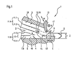
- FIG. 1 shows a schematic and sectional view of a headbox 1 for a machine for producing a merely schematically indicated fibrous web 2 from a pulp suspension 3.
- the fibrous web 2 formed from the pulp suspension 3 may in particular be a paper, board or tissue web.
- the headbox 1 has an upper nozzle wall 5 and a lower nozzle wall 6 and two side walls 7, 8, not shown, tapering to a gap 9 and a flowed through by the pulp suspension 2 nozzle chamber 10 having headbox 4.
- the nozzle chamber 10 of the headbox nozzle 4 is at least partially divided by a plurality of fins 11.1 to 11.4, which extend starting from the flow direction R (arrow) inlet side nozzle end 12 into the nozzle chamber 10.
- a positionable and over the machine width B (arrow) extending aperture 13 is arranged on the outlet side of the upper nozzle wall 5.
- the aperture 13 is, for example, of several, across the machine width B (arrow) Distributed and not shown adjusting devices (arrow 14), in particular spindle drives, for the purpose of their positioning applied.
- the respective longer lamella 11.1, 11.2 has a lamella length LL in the range of 75% (representation) to 130% (dashed line), preferably in the range of 80 to 120% of the length LD of the headbox nozzle 4.
- the respective shorter lamella 11.3, 11.4 has a lamellar length LL in the range of ⁇ 80%, preferably ⁇ 75%, of the length LD of the headbox nozzle 4. So there are slats 11.1, 11.2 and 11.3, 11.4 provided with only two different slat lengths LL. At least some, preferably all slats 11.1 to 11.4 can have an adjustable slat length LL.
- the longer fins 11.1, 11.2 are provided at least in regions with a structured surface 15.
- the structured surface 15 forms a downstream and structured fin tip 16, which structure may be in the form of grooves of rectangular and / or wedge-shaped and / or parabolic and / or round shape with constant and / or different depths.
- the iris-free lower nozzle wall 6 - seen in the flow direction R (arrow) of the pulp suspension 3 - has a preferably adjustable supernatant L in the range of 0 to 20 mm, preferably in the range of 0 to 10 mm, relative to the diaphragm 13 on.
- the adjustability of the supernatant L is indicated by a double arrow E.
- the iris-free lower nozzle wall 6 - seen in the flow direction R (arrow) of the pulp suspension 3 - a preferably adjustable board V of supernatant L to gap height s in the range of 0 to 10, preferably in the range of 1 to 5, on.
- the preferably adjustable board V of the lower nozzle wall 6 is on the German Offenlegungsschrift DE 103 24 711 A1 directed.
- the orifice 13 of the headbox 1 may moreover have a main surface 17 which is in contact with the pulp suspension 3 and runs parallel to the inner surface 18 of the upper nozzle wall 5.
- this "parallel diaphragm" 13 is based on the German patent application DE 10 2004 047 879 A1 directed.
- FIG. 1 the velocity profile G in the z-direction (height direction, double arrow) of the pulp suspension jet formed from the pulp suspension 3 is shown.
- This velocity profile G has due to the asymmetric arrangement of the slats 11.1, 11.2 and 11.3, 11.4 as well as a clear asymmetry.
- the beam is significantly slower on the upper side, ie on the side with the longer fins 11.1, 11.2.
- FIG. 2 shows a schematic and sectional side view of a downstream part of a first embodiment of a headbox 4 of a headbox 1 according to the invention with downstream Spaltformer 200th
- the gap former 200 has two endless sieves 201, 202, each forming a sieve loop 203, 204, of which the first sieve 201 is guided via a forming device 205 with a curved support surface 206 and the second sieve 202 is guided over a further element 207. Thereafter, the two screens 201, 202 together to form a wedge-shaped material inlet gap 208, which receives the fibrous suspension 3 directly from the headbox 1 according to the invention. Subsequently, the two sieves 203, 204 with the introduced pulp suspension 3 form a twin-wire section 209.
- the former 205 is configured as a forming roller 210, whereas the other member 207 is configured as a breast roller 211.
- the shaping device 205 can also be designed as a forming shoe in a further embodiment.
- the aperture 13 having the upper nozzle wall 5 is mutually arranged in the present embodiment of the former 205.
- FIG. 3 shows a schematic and sectional side view of a downstream part of a second embodiment of a headbox 4 of a head box 1 according to the invention with downstream Spaltformer 200th
- the aperture 13 having the upper nozzle wall 5 is arranged on the same side of the former 205.
- the lower nozzle wall 6 is again glare-free.
- a headbox of the type mentioned is further developed such that on the one hand, the two-sidedness of the layer orientation between the top and bottom of the fibrous web can be selectively influenced and on the other hand leaf disorders, for example in the form of white spots, improved can be avoided.
Landscapes
- Paper (AREA)
Abstract
Description
Die Erfindung betrifft einen Stoffauflauf für eine Maschine zur Herstellung einer Faserstoffbahn aus einer Faserstoffsuspension, mit einer eine obere Düsenwand und eine untere Düsenwand sowie zwei Seitenwände aufweisenden, sich zu einem Spalt verjüngenden und einen von der Faserstoffsuspension durchströmten Düsenraum aufweisenden Stoffauflaufdüse, wobei der Düsenraum der Stoffauflaufdüse zumindest bereichsweise durch mehrere Lamellen unterteilt ist, die sich ausgehend von dem in Strömungsrichtung eintrittsseitigen Düsenende in den Düsenraum erstrecken, und wobei an der oberen Düsenwand auslaufseitig eine positionierbare und sich über die Maschinenbreite erstreckende Blende angeordnet ist.The invention relates to a headbox for a machine for producing a fibrous web from a pulp suspension, having a headbox having an upper nozzle wall and a lower nozzle wall and two side walls, tapering to a gap and a flowed through by the pulp suspension nozzle headbox, wherein the nozzle space of the headbox at least partially divided by a plurality of slats extending from the inlet end in the flow direction end of the nozzle into the nozzle chamber, and wherein on the upper nozzle wall outlet side a positionable and extending over the machine width aperture is arranged.
Bei der aus der Faserstoffsuspension gebildeten Faserstoffbahn kann es sich insbesondere um eine Papier-, Karton- oder Tissuebahn handeln.The fibrous web formed from the pulp suspension may in particular be a paper, board or tissue web.
Ein derartiger Stoffauflauf ist beispielsweise aus den europäischen Patentanmeldungen
Der Grund für die Asymmetrie der Layer Orientation wird in Fachkreisen im asymmetrischen Aufbau konventioneller Stoffauflaufdüsen gesehen, da bei der Strömungsumlenkung an der verwendeten Blende die in der Faserstoffsuspension enthaltenen Fasern vermehrt in Maschinenlaufrichtung ausgerichtet werden. Auf der gegenüber liegenden, blendenfreien unteren Düsenwand, die über die Blende hinausragt, findet eine Ausrichtung in Maschinenlaufrichtung durch eine erhöhte Mikroturbulenz in der Faserstoffsuspension, bedingt unter anderem durch eine Wandreibung auf hohem Geschwindigkeitsniveau, dagegen nicht oder nur eingeschränkt statt.The reason for the asymmetry of the layer orientation is seen in professional circles in the asymmetric structure of conventional headbox nozzles, since in the flow deflection at the aperture used, the fibers contained in the pulp suspension are increasingly aligned in the machine direction. On the opposite, glare-free lower nozzle wall, which protrudes beyond the diaphragm, is an alignment in the machine direction by increased microturbulence in the pulp suspension, due, inter alia, by a wall friction at a high speed level, but not or only limited instead.
Es ist zwar schon versucht worden, wie beispielsweise in der bereits genannten
Eine weitere Möglichkeit zur Herstellung von kritischen holzfreien Faserstoffbahnen ist der Einsatz eines dem Fachmann bekannten und in der
Es ist also Aufgabe der Erfindung, einen Stoffauflauf der eingangs genannten Art derart zu verbessern, dass einerseits die Zweiseitigkeit der Layer Orientation zwischen der Ober- und der Unterseite der Faserstoffbahn gezielt beeinflusst werden kann und dass andererseits Blattstörungen, beispielsweise in Form von weißen Flecken, verbessert vermieden werden können.It is therefore an object of the invention to improve a headbox of the type mentioned in such a way that on the one hand, the two-sidedness of the layer orientation between the top and bottom of the fibrous web can be selectively influenced and on the other hand sheet disturbances, for example in the form of white spots, improved can be avoided.
Diese Aufgabe wird bei einem Stoffauflauf der eingangs genannten Art erfindungsgemäß dadurch gelöst, dass die blendenfreie weitere Düsenwand - in Strömungsrichtung der Faserstoffsuspension gesehen - einen vorzugsweise einstellbaren Überstand im Bereich von 0 bis 20 mm, vorzugsweise im Bereich von 0 bis 10 mm, gegenüber der Blende aufweist und dass eine Kombination von wenigstens einer längeren Lamelle und wenigstens einer kürzeren Lamelle vorgesehen ist, wobei die jeweilige längere Lamelle der die Blende aufweisenden oberen Düsenwand zugeordnet ist.This object is achieved in a headbox of the type mentioned in the present invention that the non-dazzle further nozzle wall - seen in the flow direction of the pulp suspension - a preferably adjustable supernatant in the range of 0 to 20 mm, preferably in the range of 0 to 10 mm, relative to the diaphragm and that a combination of at least one longer lamella and at least one shorter lamella is provided, wherein the respective longer lamella of the aperture having upper nozzle wall is associated.
Die erfindungsgemäße Aufgabe wird auf diese Weise vollkommen gelöst.The object of the invention is completely solved in this way.
In durchgeführten Versuchen hat sich gezeigt, dass durch die Anordnung der Lamellen in der Stoffauflaufdüse das Geschwindigkeitsprofil in der z-Richtung (Höhenrichtung) des Faserstoffsuspensionsstrahls direkt beeinflusst werden kann. So kann beispielsweise durch den gezielten Einsatz von mindestens einer längeren Lamelle in einer Hälfte der Stoffauflaufdüse die Geschwindigkeit in dieser Hälfte durch eine erhöhte Reibung zwischen der mindestens einen längeren Lamelle und der Faserstoffsuspension reduziert werden. Diese reduzierte Geschwindigkeit bei einer gleichzeitig erhöhten Mikroturbulenz in der Faserstoffsuspension begünstigt eine Nichtausrichtung der in der Faserstoffsuspension enthaltenen Fasern in Maschinenlaufrichtung.Experiments carried out have shown that the arrangement of the lamellae in the headbox nozzle can directly influence the velocity profile in the z-direction (height direction) of the pulp suspension jet. Thus, for example, by the targeted use of at least one longer lamella in one half of the headbox nozzle, the speed in this half can be reduced by increased friction between the at least one longer lamella and the pulp suspension. These Reduced speed with simultaneously increased microturbulence in the pulp suspension promotes non-orientation of the fibers in the machine direction in the pulp suspension.
Somit findet bei der Verwendung des erfindungsgemäßen Stoffauflaufs trotz des Vorhandenseins einer Blende und der damit verbundenen Strömungsumlenkung der Faserstoffsuspension eine Ausrichtung der in der Faserstoffsuspension enthaltenen Fasern quasi nicht statt. Die Zweiseitigkeit der Layer Orientation wird infolgedessen deutlich reduziert, in idealer Weise sogar vollständig vermieden.Thus, in spite of the presence of an orifice and the associated flow deflection of the pulp suspension, orientation of the fibers contained in the pulp suspension virtually does not take place when using the head box according to the invention. As a result, the two-sidedness of the layer orientation is significantly reduced, ideally even completely avoided.
Aufgrund des erfindungsgemäßen Vorteils, dass die Zweiseitigkeit der Layer Orientation zwischen der Ober- und der Unterseite der Faserstoffbahn gezielt beeinflusst werden kann, kann der Stoffauflauf, ja sogar die Maschine auch den Anforderungen verschiedenster holzfreier Faserstoffbahnen angepasst werden.Due to the inventive advantage that the two-sidedness of the layer orientation between the top and bottom of the fibrous web can be selectively influenced, the headbox, and even the machine can be adapted to the requirements of different wood-free fibrous webs.
Unter dem Begriff "Zuordnung" wird im vorliegenden Fall die räumliche Lage einer Lamelle innerhalb der Stoffauflaufdüse beschrieben. Die Stoffauflaufdüse eines Einschichtenstoffauflaufs kann grundsätzlich in zwei Hälften unterteilt werden, wobei eine Hälfte benachbart zu der die Blende aufweisenden Düsenwand angeordnet ist. Die "Zuordnung" einer Lamelle zu der die Blende aufweisenden oberen Düsenwand bedeutet also, dass sie räumlich in der dieser oberen Düsenwand benachbarten Hälfte der Stoffauflaufdüse angeordnet ist.In the present case, the term "assignment" describes the spatial position of a lamella within the headbox nozzle. The headbox nozzle of a Einschichtenstoffauflaufs can basically be divided into two halves, wherein one half is disposed adjacent to the nozzle wall having the aperture. The "assignment" of a lamella to the diaphragm having the upper nozzle wall thus means that it is spatially arranged in the upper nozzle wall of this adjacent half of the headbox nozzle.
Im Hinblick auf den praktischen Anwendungsfall weist der erfindungsgemäße Stoffauflauf also wenigstens zwei Gruppen von Lamellen auf, eine erste Gruppe mit längeren Lamellen, die der die Blende aufweisenden oberen Düsenwand zugeordnet ist, und wenigstens eine weitere, insbesondere ein zweite Gruppe mit kürzeren Lamellen, die der die Blende aufweisenden oberen Düsenwand abgewandt ist.With regard to the practical application, the headbox according to the invention thus has at least two groups of lamellae, a first group with longer lamellae, which is associated with the upper nozzle wall having the diaphragm, and at least one further, in particular a second group with shorter lamellae, the facing away from the aperture upper nozzle wall.
In einer ersten bevorzugten Ausführungsform ist vorgesehen, dass alle längeren Lamellen der die Blende aufweisenden oberen Düsenwand zugeordnet sind. Damit kann aufgrund des in der Stoffauflaufdüse herrschenden Geschwindigkeitsquerprofils in effektiver Weise der Zweiseitigkeit der Layer Orientation entgegen gewirkt werden.In a first preferred embodiment, it is provided that all the longer lamellae are associated with the upper nozzle wall having the orifice. Thus, the two-sidedness of the layer orientation can effectively be counteracted due to the velocity profile prevailing in the headbox nozzle.
Die jeweilige längere Lamelle weist bevorzugt eine Lamellenlänge im Bereich von 75 bis 130 %, vorzugsweise im Bereich von 80 bis 120 % der Länge der Stoffauflaufdüse auf. Sollte diese jeweilige längere Lamelle über die Blende hinaus stehen, so sollte sie zur Vermeidung von Blattstörungen, beispielsweise in Form von weißen Flecken, einen Überstand von 0 bis 20 mm aus der Stoffauflaufdüse heraus nicht überschreiten. Hingegen weist die jeweilige kürzere Lamelle bevorzugt eine Lamellenlänge im Bereich von ≤ 80 %, vorzugsweise ≤ 75 % der Länge der Stoffauflaufdüse auf. Dabei können in weiterer Ausgestaltung zumindest einige, vorzugsweise alle Lamellen eine einstellbare Lamellenlänge aufweisen. Entsprechende Einrichtungen zur Einstellung von Lamellenlängen sind dem Fachmann aus einer Vielzahl von Veröffentlichungen bekannt.The respective longer lamella preferably has a lamella length in the range of 75 to 130%, preferably in the range of 80 to 120% of the length of the headbox nozzle. Should this particular longer lamella be beyond the aperture, it should not exceed a protrusion of 0 to 20 mm from the headbox to avoid leaf disturbances, for example in the form of white spots. By contrast, the respective shorter lamella preferably has a lamellar length in the range of ≦ 80%, preferably ≦ 75%, of the length of the headbox nozzle. In this case, in a further embodiment, at least some, preferably all slats have an adjustable slat length. Corresponding devices for adjusting slat lengths are known to the person skilled in the art from a large number of publications.
Im Hinblick auf einen hohen Standardisierungsgrad und eine geringe Lagerhaltung sind in weiterer günstiger Ausführungsform Lamellen mit nur zwei unterschiedlichen Lamellenlängen vorgesehen. Dies erbringt zudem den Vorteil einer verbesserten Austauschbarkeit von Lamellen.In view of a high degree of standardization and low storage levels are provided in a further favorable embodiment slats with only two different slat lengths. This also provides the advantage of improved interchangeability of lamellae.
Weiterhin sind bevorzugt zumindest einige, vorzugsweise alle Lamellen wenigstens bereichsweise mit einer strukturierten Oberfläche versehen. Diese strukturierte Oberfläche kann beispielsweise eine stromabwärtige und strukturierte Lamellenspitze sein, wobei die Struktur die Form von Nuten mit rechteckiger und/oder keilförmiger und/oder parabelförmiger und/oder runder Form mit konstanter und/oder unterschiedlicher Tiefe umfassen kann. Durch diese vorgeschlagene Geometrie ergibt sich der Vorteil der Erreichbarkeit von stabilen Strömungsverhältnissen auch bei asymmetrischen Strömungskanälen und der bestmöglichen Anströmung des strukturierten stromabwärtigen Lamellenendes hinsichtlich einer Wirbelvermeidung.Furthermore, at least some, preferably all lamellae are preferably provided at least in regions with a structured surface. This structured surface may, for example, be a downstream and structured lamella tip, wherein the structure may take the form of grooves of rectangular and / or wedge-shaped and / or parabolic and / or round shape with constant and / or different depth. This proposed geometry results in the advantage of the availability of stable flow conditions even with asymmetric flow channels and the best possible flow of the structured downstream fin end with respect to a vortex avoidance.
Allgemein kann die blendenfreie untere Düsenwand - in Strömungsrichtung der Faserstoffsuspension gesehen - einen vorzugsweise einstellbaren Vorstand von Überstand zu Spalthöhe im Bereich von 0 bis 10, vorzugsweise im Bereich von 1 bis 5 aufweisen, da in diesem Bereich der Einfluss der blendenfreien unteren Düsenwand auf die Layer Orientation in hervorragender Weise minimiert werden kann.In general, the iris-free lower nozzle wall-viewed in the flow direction of the pulp suspension-can have a preferably adjustable board from projection to gap height in the range from 0 to 10, preferably in the range from 1 to 5, since in this area the influence of the iris-free lower nozzle wall on the layers Orientation can be minimized in an excellent way.
Überdies kann es vorteilhaft sein, wenn die Blende eine von der Faserstoffsuspension berührte Hauptfläche aufweist, die parallel zur Innenfläche der dazugehörigen oberen Düsenwand verläuft. Dies erbringt eine strömungstechnisch optimale Gestaltung des Endbereichs der Stoffauflaufdüse, insbesondere der Blende zur Reduzierung der Strahlkontraktion.Moreover, it may be advantageous if the diaphragm has a main surface touched by the pulp suspension which runs parallel to the inner surface of the associated upper nozzle wall. This provides a fluidically optimal design of the end region of the headbox, in particular the aperture for reducing the jet contraction.
In einer Maschine zur Herstellung einer Faserstoffsbahn aus einer Faserstoffsuspension kann dem erfindungsgemäßen Stoffauflauf ferner in Maschinenlaufrichtung ein Spaltformer mit zwei endlosen, je eine Siebschlaufe bildenden Sieben nachgeordnet sein, von denen das erste Sieb über eine Formiereinrichtung mit einer gekrümmten Stützfläche geführt ist und das zweite Sieb über ein weiteres Element geführt ist, die beiden Siebe danach unter Bildung eines keilförmigen Stoffeinlaufspalts, der unmittelbar von dem erfindungsgemäßen Stoffauflauf die Faserstoffsuspension aufnimmt, im Bereich der Formiereinrichtung oder nach dem Ablauf der beiden Siebe von dem jeweiligen Element zusammenlaufen und anschließend eine Doppelsiebstrecke bilden.In a machine for producing a fibrous web from a pulp suspension, the headbox according to the invention can also be followed by a gap former with two endless sieves, each forming a sieve loop, of which the first sieve is guided via a forming device with a curved support surface and the second sieve over a further element is passed, the two sieves thereafter together to form a wedge-shaped material inlet gap which receives the fibrous suspension directly from the headbox according to the invention, converge in the region of the former or after the expiration of the two sieves of the respective element and then form a Doppelsiebstrecke.
Dabei kann die die Blende aufweisende obere Düsenwand gleich- oder gegenseitig der Formiereinrichtung angeordnet sein. Im Falle einer gegenseitigen Anordnung erhält man durch die Fliehkräfte eine stärkere Entwässerung an der außen liegenden Seite, wobei zudem das Strahlgeschwindigkeitsprofil, also die Wirkung der dort eingesetzten längeren Lamellen, sofort eingefroren wird. Ein ähnliches Ergebnis wird auch erreicht, wenn sich Blende und die gekrümmte Stützfläche der Formiereinrichtung auf der gleichen Seite befinden.In this case, the aperture upper nozzle wall may be the same or mutually arranged the forming device. In the case of a mutual arrangement obtained by the centrifugal forces a stronger drainage on the outer side, in addition, the jet velocity profile, ie the effect of the longer slats used there, immediately frozen. A similar result is also achieved when the shutter and the curved support surface of the former are on the same side.
Die Formiereinrichtung weist unter technologischen Aspekten bevorzugt zumindest eine Formierwalze oder einen Formierschuh auf, wohingegen das weitere Element zumindest eine Brustwalze aufweisen kann.The shaping device preferably has at least one forming roller or a forming shoe from a technological point of view, whereas the further element may comprise at least one breast roll.
Weitere Merkmale und Vorteile der Erfindung ergeben sich aus der nachfolgenden Beschreibung bevorzugter Ausführungsbeispiele unter Bezugnahme auf die Zeichnung.Further features and advantages of the invention will become apparent from the following description of preferred embodiments with reference to the drawings.
Es zeigen
- Figur 1
- eine schematische und geschnittene Seitenansicht eines stromabwärtigen Teils einer Stoffauflaufdüse eines erfindungsgemäßen Stoffauflaufs, und
Figuren 2 und 3- zwei schematische und geschnittene Seitenansichten eines stromabwärtigen Teils von zwei weiteren Ausführungsformen einer Stoffauflaufdüse eines erfindungsgemäßen Stoffauflaufs mit nachgeordnetem Spaltformer.
- FIG. 1
- a schematic and sectional side view of a downstream part of a headbox of a head box according to the invention, and
- FIGS. 2 and 3
- two schematic and sectional side views of a downstream part of two further embodiments of a headbox of a headbox according to the invention with downstream Spaltformer.
Die
Der Stoffauflauf 1 weist eine eine obere Düsenwand 5 und eine untere Düsenwand 6 sowie zwei nicht dargestellte Seitenwände 7, 8 aufweisende, sich zu einem Spalt 9 verjüngende und einen von der Faserstoffsuspension 2 durchströmten Düsenraum 10 aufweisende Stoffauflaufdüse 4 auf.The headbox 1 has an
Der Düsenraum 10 der Stoffauflaufdüse 4 ist zumindest bereichsweise durch mehrere Lamellen 11.1 bis 11.4 unterteilt, die sich ausgehend von dem in Strömungsrichtung R (Pfeil) eintrittsseitigen Düsenende 12 in den Düsenraum 10 erstrecken.The nozzle chamber 10 of the
Ferner ist an der oberen Düsenwand 5 auslaufseitig eine positionierbare und sich über die Maschinenbreite B (Pfeil) erstreckende Blende 13 angeordnet. Die Blende 13 ist beispielsweise von mehreren, über die Maschinenbreite B (Pfeil) verteilten und nicht dargestellten Stelleinrichtungen (Pfeil 14), insbesondere Spindelantrieben, zwecks deren Positionierung beaufschlagt.Further, a positionable and over the machine width B (arrow) extending
Es ist eine Kombination von zwei längeren Lamellen 11.1, 11.2 und zwei kürzeren Lamellen 11.3, 11.4 vorgesehen, wobei die jeweilige längere Lamelle 11.1, 11.2 der die Blende 13 aufweisenden oberen Düsenwand 5 zugeordnet ist. Kurzum, es sind zwei Gruppen 11.A, 11.B von Lamellen 11.1 bis 11.4 vorgesehen, eine erste Gruppe 11.A mit längeren Lamellen 11.1, 11.2, die der die Blende 13 aufweisenden oberen Düsenwand 5 zugeordnet ist, und eine zweite Gruppe 11.B mit kürzeren Lamellen 11.3, 11.4, die der die Blende 13 aufweisenden oberen Düsenwand 5 abgewandt ist. Dabei sollten die Lamellen 11.1, 11.2 (Blende 13) in Summe länger sein als die Lamellen 11.3, 11.4.It is a combination of two longer slats 11.1, 11.2 and two shorter slats 11.3, 11.4 provided, wherein the respective longer slat 11.1, 11.2 of the
Die jeweilige längere Lamelle 11.1, 11.2 weist eine Lamellenlänge LL im Bereich von 75 % (Darstellung) bis 130 % (Strichelung), vorzugsweise im Bereich von 80 bis 120 % der Länge LD der Stoffauflaufdüse 4 auf. Hingegen weist die jeweilige kürzere Lamelle 11.3, 11.4 eine Lamellenlänge LL im Bereich von ≤ 80 %, vorzugsweise ≤ 75 % der Länge LD der Stoffauflaufdüse 4 auf. Es sind also Lamellen 11.1, 11.2 und 11.3, 11.4 mit nur zwei unterschiedlichen Lamellenlängen LL vorgesehen. Zumindest einige, vorzugsweise alle Lamellen 11.1 bis 11.4 können eine einstellbare Lamellenlänge LL aufweisen.The respective longer lamella 11.1, 11.2 has a lamella length LL in the range of 75% (representation) to 130% (dashed line), preferably in the range of 80 to 120% of the length LD of the
Weiterhin sind zumindest die längeren Lamellen 11.1, 11.2 wenigstens bereichsweise mit einer strukturierten Oberfläche 15 versehen. Die strukturierte Oberfläche 15 bildet eine stromabwärtige und strukturierte Lamellenspitze 16, wobei die Struktur die Form von Nuten mit rechteckiger und/oder keilförmiger und/oder parabelförmiger und/oder runder Form mit konstanter und/oder unterschiedlicher Tiefe umfassen kann.Furthermore, at least the longer fins 11.1, 11.2 are provided at least in regions with a structured surface 15. The structured surface 15 forms a downstream and structured fin tip 16, which structure may be in the form of grooves of rectangular and / or wedge-shaped and / or parabolic and / or round shape with constant and / or different depths.
Die blendenfreie untere Düsenwand 6 - in Strömungsrichtung R (Pfeil) der Faserstoffsuspension 3 gesehen - weist einen vorzugsweise einstellbaren Überstand L im Bereich von 0 bis 20 mm, vorzugsweise im Bereich von 0 bis 10 mm, gegenüber der Blende 13 auf. Die Einstellbarkeit des Überstands L ist mittels eines Doppelpfeils E angedeutet. Grundsätzlich weist die blendenfreie untere Düsenwand 6 - in Strömungsrichtung R (Pfeil) der Faserstoffsuspension 3 gesehen - einen vorzugsweise einstellbaren Vorstand V von Überstand L zu Spalthöhe s im Bereich von 0 bis 10, vorzugsweise im Bereich von 1 bis 5, auf. Hinsichtlich der weiteren Ausgestaltung des vorzugsweise einstellbaren Vorstands V der unteren Düsenwand 6 wird auf die
Die Blende 13 des Stoffauflaufs 1 kann überdies eine von der Faserstoffsuspension 3 berührte Hauptfläche 17 aufweisen, die parallel zur Innenfläche 18 der oberen Düsenwand 5 verläuft. Hinsichtlich der weiteren Ausgestaltung dieser "Parallel-Blende" 13 wird auf die deutsche Offenlegungsschrift
Und letztlich ist in der
Die
Der Spaltformer 200 weist zwei endlose, je eine Siebschlaufe 203, 204 bildende Siebe 201, 202 auf, von denen das erste Sieb 201 über eine Formiereinrichtung 205 mit einer gekrümmten Stützfläche 206 geführt ist und das zweite Sieb 202 über ein weiteres Element 207 geführt ist. Danach laufen die beiden Siebe 201, 202 unter Bildung eines keilförmigen Stoffeinlaufspalts 208 zusammen, der unmittelbar von dem erfindungsgemäßen Stoffauflauf 1 die Faserstoffsuspension 3 aufnimmt. Anschließend bilden die beiden Siebe 203, 204 mit der eingebrachten Faserstoffsuspension 3 eine Doppelsiebstrecke 209.The gap former 200 has two
Die Formiereinrichtung 205 ist als eine Formierwalze 210 ausgeführt, wohingegen das weitere Element 207 als eine Brustwalze 211 ausgeführt ist. Die Formiereinrichtung 205 kann in weiterer Ausgestaltung auch als ein Formierschuh ausgeführt sein.The former 205 is configured as a forming
Hinsichtlich des grundsätzlichen konstruktiven Aufbaus des Stoffauflaufs 1 samt Lamellen 11.1 bis 11.4 wird auf die Beschreibung des als Einschichtenstoffauflauf ausgebildeten Stoffauflaufs 1 der
Die die Blende 13 aufweisende obere Düsenwand 5 ist in vorliegender Ausführung gegenseitig der Formiereinrichtung 205 angeordnet. Die untere Düsenwand 6 hingegen ist blendenfrei.The
Die
Da diese Ausführungsform sich mit der in der
In dieser Ausführungsform ist die die Blende 13 aufweisende obere Düsenwand 5 gleichseitig der Formiereinrichtung 205 angeordnet. Die untere Düsenwand 6 ist wiederum blendenfrei.In this embodiment, the
Zusammenfassend ist festzuhalten, dass durch die Erfindung ein Stoffauflauf der eingangs genannten Art derart weitergebildet wird, dass einerseits die Zweiseitigkeit der Layer Orientation zwischen der Ober- und der Unterseite der Faserstoffbahn gezielt beeinflusst werden kann und dass andererseits Blattstörungen, beispielsweise in Form von weißen Flecken, verbessert vermieden werden können.In summary, it should be noted that the invention a headbox of the type mentioned is further developed such that on the one hand, the two-sidedness of the layer orientation between the top and bottom of the fibrous web can be selectively influenced and on the other hand leaf disorders, for example in the form of white spots, improved can be avoided.
- 11
- Stoffauflaufheadbox
- 22
- FaserstoffbahnFibrous web
- 33
- FaserstoffsuspensionFibrous suspension
- 3.13.1
- FaserstoffsuspensionFibrous suspension
- 3.23.2
- FaserstoffsuspensionFibrous suspension
- 44
- Stoffauflaufdüseheadbox
- 55
- Obere DüsenwandUpper nozzle wall
- 66
- Untere DüsenwandLower nozzle wall
- 77
- SeitenwandSide wall
- 88th
- SeitenwandSide wall
- 99
- Spaltgap
- 1010
- Düsenraumnozzle chamber
- 11.1, 11.211.1, 11.2
- Längere LamelleLonger lamella
- 11.3, 11.411.3, 11.4
- Kürzere LamelleShorter slat
- 11.A11.A
- Lamellengruppefin group
- 11.B11.B
- Lamellengruppefin group
- 1212
- Düsenendenozzle end
- 1313
- Blendecover
- 1414
- Stelleinrichtungen (Pfeil)Control devices (arrow)
- 1515
- Oberflächesurface
- 1616
- Lamellenspitzelamella tip
- 1717
- Hauptflächemain area
- 1818
- Innenflächepalm
- 200200
- Spaltformergap former
- 201201
- Erstes SiebFirst sieve
- 202202
- Zweites SiebSecond sieve
- 203203
- Siebschlaufewire loop
- 204204
- Siebschlaufewire loop
- 205205
- Formiereinrichtungforming device
- 206206
- Gekrümmte StützflächeCurved support surface
- 207207
- Elementelement
- 208208
- StoffeinlaufspaltStock inlet gap
- 209209
- Doppelsiebstrecketwin-wire
- 210210
- Formierwalzeforming roll
- 211211
- Brustwalzebreast roll
- BB
- Maschinenbreite (Pfeil)Machine width (arrow)
- Ee
- Doppelpfeildouble arrow
- GG
- Geschwindigkeitsprofilvelocity profile
- LL
- ÜberstandGot over
- LDLD
- Länge (Stoffauflaufdüse)Length (headbox nozzle)
- LLLL
- Lamellenlängelamellar length
- RR
- Strömungsrichtung (Pfeil)Flow direction (arrow)
- ss
- Spalthöhegap height
- VV
- VorstandBoard
- zz
- Höhenrichtung (Doppelpfeil)Height direction (double arrow)
Claims (12)
- Headbox (1) for a machine for producing a fibrous web (2) from a fibrous suspension (3), comprising a headbox nozzle (4) having an upper nozzle wall (5) and a lower nozzle wall (6) and also two side walls (7, 8), tapering to a slot (9), and a nozzle chamber (10) through which the fibrous suspension (3) flows, the nozzle chamber (10) of the headbox nozzle (4) being subdivided, at least in some regions, by a plurality of slats (11.1 to 11.4) which, starting from the nozzle end (2) on the inlet side in the flow direction (R), extend into the nozzle chamber (10), and there being arranged on the upper nozzle wall (5) on the outlet side a slice (13) that can be positioned and that extends over the machine width (B),
characterized in that
the lower nozzle wall (6) that has no slice - seen in the flow direction (R) of the fibrous suspension - has a preferably adjustable projection (L) in the range from 0 to 20 mm, preferably in the range from 0 to 10 mm, with respect to the slice (13), and
in that a combination of at least one longer slat (11.1, 11.2) and at least one shorter slat (11.3, 11.4) is provided, the respective longer slat (11.1, 11.2) being assigned to the upper nozzle wall (5) having the slice (13). - Headbox (1) according to Claim 1,
characterized in that
all the longer slats (11.1, 11.2) are assigned to the upper nozzle wall (5) having the slice (13). - Headbox (1) according to Claim 1 or 2, characterized in that
the respective longer slat (11.1, 11.2) has a slat length (LL) in the range from 75 to 130%, preferably in the range from 80 to 120%, of the length (LD) of the headbox nozzle (4). - Headbox (1) according to one of the preceding claims,
characterized in that
the respective shorter slat (11.3, 11.4) has a slat length (LL) in the region of ≤ 80%, preferably ≤ 75%, of the length (LD) of the headbox nozzle (4). - Headbox (1) according to one of the preceding claims,
characterized in that
at least some, preferably all, slats (11.1 to 11.4) have an adjustable slat length (LL). - Headbox (1) according to one of the preceding claims,
characterized in that
slats (11.1 to 11.4) having only two different slat lengths (LL) are provided. - Headbox (1) according to one of the preceding claims,
characterized in that
at least some, preferably all, slats (11.1 to 11.4) are provided with a structured surface (15), at least in some regions. - Headbox (1) according to one of the preceding claims, in particular according to Claim 7,
characterized in that
the lower nozzle wall (6) that has no slice - seen in the flow direction (R) of the fibrous suspension (3) - has a preferably adjustable forward protrusion (V) from projection (L) to slot height (s) in the range from 0 to 10, preferably in the range from 1 to 5. - Headbox (1) according to one of the preceding claims,
characterized in that
the slice (13) has a main surface (17) which is touched by the fibrous suspension (3) and which runs parallel to the inner surface (18) of the associated upper nozzle wall (5). - Machine for producing a fibrous web (2) from a fibrous suspension (3), comprising a headbox (1), downstream of which in the machine running direction there is arranged a gap former (200) having two endless wires (201, 202) each forming a wire loop (203, 204), of which the first wire (201) is led over a forming device (205) having a curved supporting surface (206), and the second wire (202) is led over a further element (207), the two wires (201, 202) thereafter run together in the region of the forming device (205) after the two wires have run off the respective element, forming a wedge-shaped stock inlet gap (208) which picks up the at least one fibrous suspension (3) directly from the headbox (1), and then form a twin-wire section (209),
characterized in that
the headbox (1) is formed in accordance with one of Claims 1 to 10, and in that the upper nozzle wall (5) having the slice (13) is arranged on the opposite side or the same side as the forming device (205). - Machine according to Claim 10,
characterized in that
the forming device (205) has at least one forming roll (210) or a forming shoe. - Machine according to Claim 10 or 11, characterized in that
the further element (207) has at least one breast roll (211).
Applications Claiming Priority (1)
| Application Number | Priority Date | Filing Date | Title |
|---|---|---|---|
| DE102006033847A DE102006033847A1 (en) | 2006-07-21 | 2006-07-21 | Headbox of a machine for producing a fibrous web |
Publications (2)
| Publication Number | Publication Date |
|---|---|
| EP1881106A1 EP1881106A1 (en) | 2008-01-23 |
| EP1881106B1 true EP1881106B1 (en) | 2012-03-28 |
Family
ID=38478213
Family Applications (1)
| Application Number | Title | Priority Date | Filing Date |
|---|---|---|---|
| EP07112599A Not-in-force EP1881106B1 (en) | 2006-07-21 | 2007-07-17 | Headbox of a machine for producing a sheet of fibrous material |
Country Status (3)
| Country | Link |
|---|---|
| EP (1) | EP1881106B1 (en) |
| AT (1) | ATE551470T1 (en) |
| DE (1) | DE102006033847A1 (en) |
Families Citing this family (3)
| Publication number | Priority date | Publication date | Assignee | Title |
|---|---|---|---|---|
| DE102007036945A1 (en) * | 2007-08-04 | 2009-02-05 | Voith Patent Gmbh | Method for influencing the two-sidedness of the layer orientation and headbox for carrying out the method |
| EP2199459A1 (en) * | 2008-12-16 | 2010-06-23 | Voith Patent GmbH | Sheet composition system for a machine for producing a multiple layer sheet of fibrous material |
| DE102009000696A1 (en) | 2009-02-06 | 2010-08-12 | Voith Patent Gmbh | Method for producing a multilayer fibrous web and sheet forming apparatus for carrying out the method |
Family Cites Families (7)
| Publication number | Priority date | Publication date | Assignee | Title |
|---|---|---|---|---|
| DE29713272U1 (en) * | 1997-07-25 | 1997-11-20 | Voith Sulzer Papiermaschinen GmbH, 89522 Heidenheim | Headbox to form a fiber suspension layer |
| DE10211178A1 (en) * | 2002-03-14 | 2003-09-25 | Voith Paper Patent Gmbh | Laminated outlet for production of sandwich plaster board or corrugated cardboard has bends in channel sidewalls to jet outlet |
| DE10308555A1 (en) | 2003-02-27 | 2004-10-21 | Voith Paper Patent Gmbh | headbox |
| DE10318035A1 (en) | 2003-04-19 | 2004-11-04 | Voith Paper Patent Gmbh | Stock inlet, for a multi-layer papermaking machine, has blades to separate the pulp flows with adjustable lips at the outflow gap to prevent the separated flows from intermingling |
| DE10324711A1 (en) * | 2003-05-30 | 2004-12-30 | Voith Paper Patent Gmbh | headbox |
| DE102004047879A1 (en) * | 2004-10-01 | 2006-04-06 | Voith Paper Patent Gmbh | Multi-layer regulator for production of a fibrous material course, comprises a fibrous material suspension with a nozzle wall and side panels, separating element, lamellas, and an aperture exhibits a affected main face of the suspension |
| DE102004000051A1 (en) * | 2004-11-19 | 2006-05-24 | Voith Paper Patent Gmbh | Headbox of a machine for producing a fibrous material web |
-
2006
- 2006-07-21 DE DE102006033847A patent/DE102006033847A1/en not_active Withdrawn
-
2007
- 2007-07-17 AT AT07112599T patent/ATE551470T1/en active
- 2007-07-17 EP EP07112599A patent/EP1881106B1/en not_active Not-in-force
Also Published As
| Publication number | Publication date |
|---|---|
| DE102006033847A1 (en) | 2008-01-24 |
| EP1881106A1 (en) | 2008-01-23 |
| ATE551470T1 (en) | 2012-04-15 |
Similar Documents
| Publication | Publication Date | Title |
|---|---|---|
| EP2379801B1 (en) | Sheet-forming system for a machine for producing a multilayer fibrous material web | |
| DE69707256T2 (en) | DOUBLE SCREEN FORMER WITH ROLL AND BLADE FOR A PAPER MACHINE | |
| EP2739780B1 (en) | Sheet forming system for a machine for producing a two-layer or multi-layer web | |
| EP2446083B1 (en) | Headbox for a machine for producing a fiber web | |
| DE102008054894A1 (en) | Headbox for a machine for producing a fibrous web | |
| EP1881106B1 (en) | Headbox of a machine for producing a sheet of fibrous material | |
| DE10234559A1 (en) | Papermaking machine for low-volume paper or carton has vortex generator block made of a single integral plastic unit with jets discharging to sieve belt | |
| DE10223398A1 (en) | A forming apparatus | |
| WO2012107117A1 (en) | Sheet-forming device | |
| DE69715236T3 (en) | MULTILAYER RETURN FOR A PAPER MACHINE | |
| EP0831172B1 (en) | Wire section and process for dewatering of a fibrous web in a wire section | |
| EP1403424B1 (en) | Headbox with guide vane | |
| EP2025809A2 (en) | Method for influencing the two sidedness of layer orientation and headbox for carrying out the method | |
| DE102010041332A1 (en) | Sheet formation system for machine for production of e.g. paper, has head box positionable for varying beam incidence angle and/or beam incidence line under maintenance of unchanged geometry of head box nozzle | |
| EP1659211B1 (en) | Formation system of a machine for manufacturing a fibrous web | |
| EP2205792B1 (en) | Twin-wire former | |
| EP2072677B1 (en) | Twin-wire former for a machine for producing a sheet of fibrous material from at least one suspension of fibrous material | |
| DE10393245T5 (en) | A method of forming high consistency pulp in a paper or board machine and corresponding pulp high consistency pulp of a paper or board machine | |
| EP4328376A1 (en) | Inclined screen former | |
| WO2010012676A2 (en) | Twin-wire former for a machine for producing a web of fibrous material | |
| EP1683913A1 (en) | Twin-wire former | |
| DE19908299A1 (en) | Stock inlet lip at papermaking or cardboard production machine has structured planes with transits and setting units to determine pulp flow and give lowest possible shear length ratio where pulp forms web | |
| DE202004021817U1 (en) | Sheet forming system | |
| DE4230921A1 (en) | Double fourdrinier papermaking machine - has fixed and pliable bar at water extraction zone to give adjustable pressure impact for improved paper quality | |
| DE10318035A1 (en) | Stock inlet, for a multi-layer papermaking machine, has blades to separate the pulp flows with adjustable lips at the outflow gap to prevent the separated flows from intermingling |
Legal Events
| Date | Code | Title | Description |
|---|---|---|---|
| PUAI | Public reference made under article 153(3) epc to a published international application that has entered the european phase |
Free format text: ORIGINAL CODE: 0009012 |
|
| AK | Designated contracting states |
Kind code of ref document: A1 Designated state(s): AT BE BG CH CY CZ DE DK EE ES FI FR GB GR HU IE IS IT LI LT LU LV MC MT NL PL PT RO SE SI SK TR |
|
| AX | Request for extension of the european patent |
Extension state: AL BA HR MK YU |
|
| 17P | Request for examination filed |
Effective date: 20080723 |
|
| AKX | Designation fees paid |
Designated state(s): AT BE BG CH CY CZ DE DK EE ES FI FR GB GR HU IE IS IT LI LT LU LV MC MT NL PL PT RO SE SI SK TR |
|
| 17Q | First examination report despatched |
Effective date: 20080908 |
|
| GRAP | Despatch of communication of intention to grant a patent |
Free format text: ORIGINAL CODE: EPIDOSNIGR1 |
|
| GRAS | Grant fee paid |
Free format text: ORIGINAL CODE: EPIDOSNIGR3 |
|
| GRAA | (expected) grant |
Free format text: ORIGINAL CODE: 0009210 |
|
| AK | Designated contracting states |
Kind code of ref document: B1 Designated state(s): AT BE BG CH CY CZ DE DK EE ES FI FR GB GR HU IE IS IT LI LT LU LV MC MT NL PL PT RO SE SI SK TR |
|
| REG | Reference to a national code |
Ref country code: GB Ref legal event code: FG4D Free format text: NOT ENGLISH |
|
| REG | Reference to a national code |
Ref country code: CH Ref legal event code: EP |
|
| REG | Reference to a national code |
Ref country code: AT Ref legal event code: REF Ref document number: 551470 Country of ref document: AT Kind code of ref document: T Effective date: 20120415 |
|
| REG | Reference to a national code |
Ref country code: IE Ref legal event code: FG4D Free format text: LANGUAGE OF EP DOCUMENT: GERMAN |
|
| REG | Reference to a national code |
Ref country code: DE Ref legal event code: R096 Ref document number: 502007009562 Country of ref document: DE Effective date: 20120524 |
|
| REG | Reference to a national code |
Ref country code: NL Ref legal event code: VDEP Effective date: 20120328 |
|
| PG25 | Lapsed in a contracting state [announced via postgrant information from national office to epo] |
Ref country code: LT Free format text: LAPSE BECAUSE OF FAILURE TO SUBMIT A TRANSLATION OF THE DESCRIPTION OR TO PAY THE FEE WITHIN THE PRESCRIBED TIME-LIMIT Effective date: 20120328 |
|
| LTIE | Lt: invalidation of european patent or patent extension |
Effective date: 20120328 |
|
| PG25 | Lapsed in a contracting state [announced via postgrant information from national office to epo] |
Ref country code: FI Free format text: LAPSE BECAUSE OF FAILURE TO SUBMIT A TRANSLATION OF THE DESCRIPTION OR TO PAY THE FEE WITHIN THE PRESCRIBED TIME-LIMIT Effective date: 20120328 Ref country code: GR Free format text: LAPSE BECAUSE OF FAILURE TO SUBMIT A TRANSLATION OF THE DESCRIPTION OR TO PAY THE FEE WITHIN THE PRESCRIBED TIME-LIMIT Effective date: 20120629 Ref country code: LV Free format text: LAPSE BECAUSE OF FAILURE TO SUBMIT A TRANSLATION OF THE DESCRIPTION OR TO PAY THE FEE WITHIN THE PRESCRIBED TIME-LIMIT Effective date: 20120328 |
|
| PG25 | Lapsed in a contracting state [announced via postgrant information from national office to epo] |
Ref country code: CY Free format text: LAPSE BECAUSE OF FAILURE TO SUBMIT A TRANSLATION OF THE DESCRIPTION OR TO PAY THE FEE WITHIN THE PRESCRIBED TIME-LIMIT Effective date: 20120328 |
|
| PG25 | Lapsed in a contracting state [announced via postgrant information from national office to epo] |
Ref country code: RO Free format text: LAPSE BECAUSE OF FAILURE TO SUBMIT A TRANSLATION OF THE DESCRIPTION OR TO PAY THE FEE WITHIN THE PRESCRIBED TIME-LIMIT Effective date: 20120328 Ref country code: SI Free format text: LAPSE BECAUSE OF FAILURE TO SUBMIT A TRANSLATION OF THE DESCRIPTION OR TO PAY THE FEE WITHIN THE PRESCRIBED TIME-LIMIT Effective date: 20120328 Ref country code: IS Free format text: LAPSE BECAUSE OF FAILURE TO SUBMIT A TRANSLATION OF THE DESCRIPTION OR TO PAY THE FEE WITHIN THE PRESCRIBED TIME-LIMIT Effective date: 20120728 Ref country code: CZ Free format text: LAPSE BECAUSE OF FAILURE TO SUBMIT A TRANSLATION OF THE DESCRIPTION OR TO PAY THE FEE WITHIN THE PRESCRIBED TIME-LIMIT Effective date: 20120328 Ref country code: EE Free format text: LAPSE BECAUSE OF FAILURE TO SUBMIT A TRANSLATION OF THE DESCRIPTION OR TO PAY THE FEE WITHIN THE PRESCRIBED TIME-LIMIT Effective date: 20120328 Ref country code: PL Free format text: LAPSE BECAUSE OF FAILURE TO SUBMIT A TRANSLATION OF THE DESCRIPTION OR TO PAY THE FEE WITHIN THE PRESCRIBED TIME-LIMIT Effective date: 20120328 Ref country code: SE Free format text: LAPSE BECAUSE OF FAILURE TO SUBMIT A TRANSLATION OF THE DESCRIPTION OR TO PAY THE FEE WITHIN THE PRESCRIBED TIME-LIMIT Effective date: 20120328 |
|
| PG25 | Lapsed in a contracting state [announced via postgrant information from national office to epo] |
Ref country code: SK Free format text: LAPSE BECAUSE OF FAILURE TO SUBMIT A TRANSLATION OF THE DESCRIPTION OR TO PAY THE FEE WITHIN THE PRESCRIBED TIME-LIMIT Effective date: 20120328 Ref country code: PT Free format text: LAPSE BECAUSE OF FAILURE TO SUBMIT A TRANSLATION OF THE DESCRIPTION OR TO PAY THE FEE WITHIN THE PRESCRIBED TIME-LIMIT Effective date: 20120730 |
|
| BERE | Be: lapsed |
Owner name: VOITH PATENT G.M.B.H. Effective date: 20120731 |
|
| PG25 | Lapsed in a contracting state [announced via postgrant information from national office to epo] |
Ref country code: DK Free format text: LAPSE BECAUSE OF FAILURE TO SUBMIT A TRANSLATION OF THE DESCRIPTION OR TO PAY THE FEE WITHIN THE PRESCRIBED TIME-LIMIT Effective date: 20120328 Ref country code: NL Free format text: LAPSE BECAUSE OF FAILURE TO SUBMIT A TRANSLATION OF THE DESCRIPTION OR TO PAY THE FEE WITHIN THE PRESCRIBED TIME-LIMIT Effective date: 20120328 |
|
| PLBE | No opposition filed within time limit |
Free format text: ORIGINAL CODE: 0009261 |
|
| REG | Reference to a national code |
Ref country code: DE Ref legal event code: R119 Ref document number: 502007009562 Country of ref document: DE |
|
| STAA | Information on the status of an ep patent application or granted ep patent |
Free format text: STATUS: NO OPPOSITION FILED WITHIN TIME LIMIT |
|
| PG25 | Lapsed in a contracting state [announced via postgrant information from national office to epo] |
Ref country code: MC Free format text: LAPSE BECAUSE OF NON-PAYMENT OF DUE FEES Effective date: 20120731 Ref country code: IT Free format text: LAPSE BECAUSE OF FAILURE TO SUBMIT A TRANSLATION OF THE DESCRIPTION OR TO PAY THE FEE WITHIN THE PRESCRIBED TIME-LIMIT Effective date: 20120328 |
|
| REG | Reference to a national code |
Ref country code: CH Ref legal event code: PL |
|
| 26N | No opposition filed |
Effective date: 20130103 |
|
| GBPC | Gb: european patent ceased through non-payment of renewal fee |
Effective date: 20120717 |
|
| REG | Reference to a national code |
Ref country code: DE Ref legal event code: R097 Ref document number: 502007009562 Country of ref document: DE Effective date: 20130103 |
|
| REG | Reference to a national code |
Ref country code: FR Ref legal event code: ST Effective date: 20130329 |
|
| PG25 | Lapsed in a contracting state [announced via postgrant information from national office to epo] |
Ref country code: GB Free format text: LAPSE BECAUSE OF NON-PAYMENT OF DUE FEES Effective date: 20120717 Ref country code: FR Free format text: LAPSE BECAUSE OF NON-PAYMENT OF DUE FEES Effective date: 20120731 Ref country code: DE Free format text: LAPSE BECAUSE OF NON-PAYMENT OF DUE FEES Effective date: 20130201 Ref country code: LI Free format text: LAPSE BECAUSE OF NON-PAYMENT OF DUE FEES Effective date: 20120731 Ref country code: CH Free format text: LAPSE BECAUSE OF NON-PAYMENT OF DUE FEES Effective date: 20120731 Ref country code: ES Free format text: LAPSE BECAUSE OF FAILURE TO SUBMIT A TRANSLATION OF THE DESCRIPTION OR TO PAY THE FEE WITHIN THE PRESCRIBED TIME-LIMIT Effective date: 20120709 |
|
| REG | Reference to a national code |
Ref country code: IE Ref legal event code: MM4A |
|
| PG25 | Lapsed in a contracting state [announced via postgrant information from national office to epo] |
Ref country code: BE Free format text: LAPSE BECAUSE OF NON-PAYMENT OF DUE FEES Effective date: 20120731 |
|
| PG25 | Lapsed in a contracting state [announced via postgrant information from national office to epo] |
Ref country code: IE Free format text: LAPSE BECAUSE OF NON-PAYMENT OF DUE FEES Effective date: 20120717 Ref country code: BG Free format text: LAPSE BECAUSE OF FAILURE TO SUBMIT A TRANSLATION OF THE DESCRIPTION OR TO PAY THE FEE WITHIN THE PRESCRIBED TIME-LIMIT Effective date: 20120628 Ref country code: MT Free format text: LAPSE BECAUSE OF FAILURE TO SUBMIT A TRANSLATION OF THE DESCRIPTION OR TO PAY THE FEE WITHIN THE PRESCRIBED TIME-LIMIT Effective date: 20120328 |
|
| REG | Reference to a national code |
Ref country code: AT Ref legal event code: MM01 Ref document number: 551470 Country of ref document: AT Kind code of ref document: T Effective date: 20120731 |
|
| REG | Reference to a national code |
Ref country code: DE Ref legal event code: R119 Ref document number: 502007009562 Country of ref document: DE Effective date: 20130201 |
|
| PG25 | Lapsed in a contracting state [announced via postgrant information from national office to epo] |
Ref country code: AT Free format text: LAPSE BECAUSE OF NON-PAYMENT OF DUE FEES Effective date: 20120731 |
|
| PG25 | Lapsed in a contracting state [announced via postgrant information from national office to epo] |
Ref country code: TR Free format text: LAPSE BECAUSE OF FAILURE TO SUBMIT A TRANSLATION OF THE DESCRIPTION OR TO PAY THE FEE WITHIN THE PRESCRIBED TIME-LIMIT Effective date: 20120328 |
|
| PG25 | Lapsed in a contracting state [announced via postgrant information from national office to epo] |
Ref country code: LU Free format text: LAPSE BECAUSE OF NON-PAYMENT OF DUE FEES Effective date: 20120717 |
|
| PG25 | Lapsed in a contracting state [announced via postgrant information from national office to epo] |
Ref country code: HU Free format text: LAPSE BECAUSE OF FAILURE TO SUBMIT A TRANSLATION OF THE DESCRIPTION OR TO PAY THE FEE WITHIN THE PRESCRIBED TIME-LIMIT Effective date: 20070717 |