EP1848329B1 - Device for determining cardiopulmonary volumes and flows of a living being - Google Patents
Device for determining cardiopulmonary volumes and flows of a living being Download PDFInfo
- Publication number
- EP1848329B1 EP1848329B1 EP06700675A EP06700675A EP1848329B1 EP 1848329 B1 EP1848329 B1 EP 1848329B1 EP 06700675 A EP06700675 A EP 06700675A EP 06700675 A EP06700675 A EP 06700675A EP 1848329 B1 EP1848329 B1 EP 1848329B1
- Authority
- EP
- European Patent Office
- Prior art keywords
- living
- dilution
- evaluation unit
- volume
- function
- Prior art date
- Legal status (The legal status is an assumption and is not a legal conclusion. Google has not performed a legal analysis and makes no representation as to the accuracy of the status listed.)
- Expired - Lifetime
Links
Images


Classifications
-
- A—HUMAN NECESSITIES
- A61—MEDICAL OR VETERINARY SCIENCE; HYGIENE
- A61B—DIAGNOSIS; SURGERY; IDENTIFICATION
- A61B5/00—Measuring for diagnostic purposes; Identification of persons
- A61B5/02—Detecting, measuring or recording for evaluating the cardiovascular system, e.g. pulse, heart rate, blood pressure or blood flow
- A61B5/02028—Determining haemodynamic parameters not otherwise provided for, e.g. cardiac contractility or left ventricular ejection fraction
-
- A—HUMAN NECESSITIES
- A61—MEDICAL OR VETERINARY SCIENCE; HYGIENE
- A61B—DIAGNOSIS; SURGERY; IDENTIFICATION
- A61B5/00—Measuring for diagnostic purposes; Identification of persons
- A61B5/02—Detecting, measuring or recording for evaluating the cardiovascular system, e.g. pulse, heart rate, blood pressure or blood flow
- A61B5/026—Measuring blood flow
- A61B5/0275—Measuring blood flow using tracers, e.g. dye dilution
- A61B5/028—Measuring blood flow using tracers, e.g. dye dilution by thermo-dilution
-
- A—HUMAN NECESSITIES
- A61—MEDICAL OR VETERINARY SCIENCE; HYGIENE
- A61B—DIAGNOSIS; SURGERY; IDENTIFICATION
- A61B5/00—Measuring for diagnostic purposes; Identification of persons
- A61B5/02—Detecting, measuring or recording for evaluating the cardiovascular system, e.g. pulse, heart rate, blood pressure or blood flow
- A61B5/026—Measuring blood flow
- A61B5/029—Measuring blood output from the heart, e.g. minute volume
Definitions
- the present invention relates to a device for determining at least one hemodynamic parameter of a living being, in particular a device for determining cardiopulmonary volumes and flows of a living being.
- the hemodynamic parameters are mainly characteristic volumes or volume flows, such as the cardiac output (CO), the global end-diastolic volume (GEDV) and the volume of extravascular lung water (EVLW).
- CO cardiac output
- GEDV global end-diastolic volume
- EDLW extravascular lung water
- Corresponding systems are commercially available and usually work with cold (ie a cooled bolus) as an indicator.
- cold ie a cooled bolus
- systems for transpulmonary thermodilution measurement have established themselves on the market.
- anomalies include Short circuit currents from the right atrium to the left atrium (so-called right-left shunt, RL shunt) or from the left ventricle to the right ventricle (so-called left-right shunt, LR shunt).
- this object is achieved with a device according to claim 1.
- a suitable program-technical device of the evaluation unit of a transpulmonary measuring arrangement preferably with a central venous and arterial catheter, is sufficient to detect a possible short-circuit flow from the right to the left half of the heart (RL shunt) and / or from the left to the right Cardiac (LR) shunt of the animal to be considered, without the use of aatorherzkatheters would be required, or would have to resort to pulmonary artery measurements at all.
- a model which contains the function y corresponding to the dilution curve as a convolution of the disturbance function I with several expressions containing characteristic times as model parameters.
- the terms correspond ideally to intermixed volumes or delay elements, which are simplified for the right atrium RA, the right ventricle RV, the pulmonary blood volume PBV, the extravascular thermal volume ETV, the left atrium LA and the left ventricle LV.
- the shunt can be both intracardiac and extracardiac in both directions.
- the determination of the model parameters can advantageously be carried out by the sub-steps of (i) fitting a model curve to the dilution curve (for example by means of a Levenberg-Marquardt algorithm), and (ii) determining the model parameters from the model curve.
- the model parameters can advantageously also be determined by the following partial steps: (i) determining a short-circuit peak before the dilution peak, (ii) determining a tangent to the dilution curve below the short-circuit peak, which includes the largest possible area with the dilution curve, and (iii) estimating the model parameters by means of curve parameters which are determinable from the position of the starting point of the dilution curve, the tangents of the tangent, the short-circuit peak and the dilution peak.
- a central venous and an arterial catheter unit are provided, alternative embodiments of the invention may be advantageous in which the arterial signal is detected noninvasively, for example via a tympanometric temperature measuring point or by optical methods, and / or the system disturbance is not central venous but peripherally triggered. In the latter case, it must be known only to a sufficient approximation or can be estimated, which additional delay is to be considered by the peripheral triggering.
- the disorder can be due to heat, "cold” (injection of a cooled bolus), lithium chloride injection (LiCl), indocyanine green (ICG) injection, or other indicators.
- the interference function can in principle have any (but known with sufficient accuracy) course, for example, a pseudo-stochastic distribution is possible.
- any variant of the invention described or indicated in the context of the present application may be particularly advantageous, depending on the economic and technical conditions in the individual case.
- individual features of the described embodiments are interchangeable or combinable.
- the device shown has a central venous catheter 11, which allows the injection of a cooled bolus into the superior vena cava 10 of the patient.
- a central venous catheter 11 which allows the injection of a cooled bolus into the superior vena cava 10 of the patient.
- the most exact possible compliance with given injectate temperature, amount of injectate and (as short as possible) injection duration or detection thereof is recommended.
- This can also be automated by means of a suitable metering pump 15 controlled by a control unit integrated in the evaluation unit 14. Likewise, however, a manually applied bolus injection is possible.
- An arterial catheter 12 (in the Fig. 1 indicated only by marking the measuring location), which has a temperature sensor 13 connected to the evaluation unit 14, serves to detect a time-dependent temperature signal in which a thermodilution curve y is obtained and further processed as a system response in the evaluation unit 14, which is suitably equipped according to the program.
- the cold indicator passes from the injection site 10 to the measuring site 12, the right atrium 2 and the right ventricle 3 of the heart 1, via the pulmonary artery 4, the pulmonary circulation 5 with extravasal thermal volume (ETV, approximate extravasal lung water volume EVLW) 15, the left atrium 6, the left Ventricle 7 and the aorta 8.
- ETV extravasal thermal volume
- EVLW extravasal lung water volume
- a heat pulse can be introduced via the central venous catheter 11, for which purpose it can be equipped with suitable heating means.
- an optically detectable indicator is possible, wherein for the determination of the system response of the arterial catheter 12 can be equipped with a fiber optic probe for concentration measurement.
- Fig. 3 illustrates a model according to the invention for the program equipment of the evaluation unit 14 suitable model for the consideration of the right-left shunt in the calculation of hemodynamic volumes.
- the right-left shunt is connected in parallel with the right ventricle RV and pulmonary blood volume PBV (cf. Fig. 2 ).
- a first ideally mixed volume V1 with characteristic time ⁇ 1 for the right ventricle another ideally mixed volume V2 with characteristic time ⁇ 2, for the whole of pulmonary blood volume PBV and extravasal thermal volume ETV a third ideally mixed volume V3 characteristic time ⁇ 3 and a delay element ("Delay") D3, as well as for the set of left atrium LA and left ventricle LV a fourth ideally mixed volume V4 with characteristic time ⁇ 4 set.
- the characteristic times ⁇ n are defined as the quotient of the corresponding volume Vn and the volume flow Qn by this volume.
- delay D0 Since a linear delay in the right and left halves of the heart acts equivalently on the system response (“output”) y, corresponding effects are summarized in the delay (“delay”) D0.
- the delay D0 can be taken into account by selecting a corrected start time.
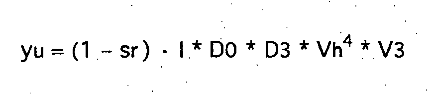
- the measured dilution curve y whose typical course occurs when a right-to-left shunt occurs in Fig. 4 sketched can be divided into two parts.
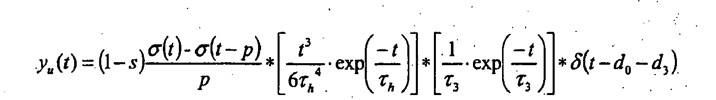
- the liquid elements of the blood which will pass through the pulmonary circulation 5 by a theoretical short-circuit-free curve yu.
- do and d3 denote the characteristic times corresponding to the delay elements D0 and D3, respectively.
- the remaining model parameters s, do and d3 may preferably be determined by a curve fitting algorithm (eg Levenberg-Marquardt algorithm).
- the calculation operations can advantageously be implemented essentially as follows in the program-technical device of the evaluation unit 14. After estimating the starting point of the dilution curve y and the dilution peak with suitable criteria, which may be derived from the prior art, the mean transit time MTT and the decay time DST are calculated. With a suitable algorithm, the model function is adapted with the least possible deviation to the measurement-determined dilution curve. With the model parameters from the adapted model function, the cardiac output CO and the shunt ratio s are calculated. Subsequently, model volumes and other hemodynamic parameters can be calculated.
- the calculation operations can advantageously also be implemented substantially as follows in the program-technical device of the evaluation unit 14. After estimating the starting point of the dilution curve y and the dilution peak with suitable criteria, which may be derived from the prior art, the average transit time MTT and the decay time DST are calculated. A shunt peak lying before the thermodilution peak is determined (see Fig. 4 ) and a tangent (dashed line in Fig. 4 ) to the dilution curve y below the short-circuit peak, which includes the largest possible area with the dilution curve y.
- characteristic curve parameters for example the starting point, the maximum of the dilution peak, the maximum of the shunt peak, the Touch points of the tangent of the area under the dilution curve y and the area between the dilution curve y and the tangent.
- the short-circuited curve yu is below the tangent.
- the area between the tangent and dilution curve y divided by the area under the dilution curve gives a lower approximate value for the right-left shunt.
- Further corrections and model parameters can be determined by regression or solving the model equations. With the model parameters, the cardiac output CO and the shunt ratio s are calculated. Subsequently, model volumes and other hemodynamic parameters can be calculated.
- an additional peak before the dilution peak can always be considered a right-left shunt.
- a right-left shunt peak can even be up to about 150% higher than the dilution peak.
- Fig. 5 Illustrated again is a series arrangement of right atrium RA, right ventricle RV, pulmonary blood volume PBV (with extravascular thermovolume to be considered as well, ETV) and all of left atrium LA and left ventricle LV.
- the left-right shunt is connected in reverse flow parallel to the right ventricle RV, pulmonary blood volume PBV, and the whole of left atrium LA and left ventricle LV.
- multiple small volumes may be simulated by a common volume with time delay.
- a first ideally mixed volume V1 with a characteristic time ⁇ 1 for the right ventricle another ideally mixed volume V2 with a characteristic time ⁇ 2, for the whole of pulmonary Blood volume PBV and extravascular thermovolume ETV a third ideally mixed volume V3 with characteristic time ⁇ 3 and a delay D3, and for the set of left atrium LA and left ventricle LV a fourth ideally mixed volume V4 with characteristic time ⁇ 4.
- the characteristic times ⁇ n are defined as the quotient of the corresponding volume Vn and the volume flow Qn by this volume.
- the delay D0 can be taken into account by selecting a corrected start time.
- the interference or input function (“input”) I can be regarded as a Dirac impact function ⁇ , ie with a vanishing duration. Usually, however, an injection takes about two seconds. In the shunt calculation, this can lead to a noteworthy error.
- the left-right shunt and the right-left shunt can be taken into account simultaneously and, moreover, preferably the recirculation through the systemic circulation 9 can be taken into account.
- the associated circuit diagram is in Fig. 7 shown.
- a first ideally mixed volume V1 with characteristic time ⁇ 1 for the right ventricle another ideally mixed volume V2 with characteristic time ⁇ 2, for the whole of pulmonary blood volume PBV and extravascular thermovolume ETV a third ideally mixed volume V3 are set up with characteristic time ⁇ 3 and a delay element D3 with characteristic time d3, for the left atrium LA a fourth ideally mixed volume V4 with characteristic time ⁇ 4, and for the left ventricle LV a fifth ideally mixed volume V5 with characteristic time ⁇ 5 ,
- the characteristic times ⁇ n are again defined as the quotient of the corresponding volume Vn and the volume flow Qn through this volume.
- Delay components in the right and left halves of the heart are in turn combined into effects in the delay D0, which can be taken into account by selecting a corrected start time.
- the left-right shunt with shunt ratio sl is connected in the reverse flow direction parallel to the right ventricle RV, pulmonary blood volume PBV, left atrium LA and left ventricle LV.
- the right-left shunt with shunt ratio sr is connected in parallel with right ventricle RV and pulmonary blood volume PBV.
- Concerning the recirculation r an ideally mixed volume V6 with a characteristic time ⁇ 6 for the systemic blood volume SBV and a delay element (D3) with a characteristic time d3 is set.
- non-diffusible intravascular indicators such as LiCI or ICG may also be used.
- non-diffusible intravascular indicators Cardiac Output ( CO) and Global End-Diastolic Volume (GEDV) can be determined but not extravascular lung water (EVLW).
- CO Cardiac Output
- GEDV Global End-Diastolic Volume
- EDLW extravascular lung water
- the algorithms can in principle remain unchanged from the algorithms described above, with the exception that the greatest intrathoracic propagation volume corresponds to the intrathoracic blood volume ITBV (in the case of the LiCI or ICG indicator) instead of the intrathoracic thermal volume ITTV (in the case of the cold indicator).
Landscapes
- Health & Medical Sciences (AREA)
- Life Sciences & Earth Sciences (AREA)
- Cardiology (AREA)
- Medical Informatics (AREA)
- Surgery (AREA)
- Biophysics (AREA)
- Pathology (AREA)
- Engineering & Computer Science (AREA)
- Biomedical Technology (AREA)
- Heart & Thoracic Surgery (AREA)
- Physiology (AREA)
- Molecular Biology (AREA)
- Physics & Mathematics (AREA)
- Animal Behavior & Ethology (AREA)
- General Health & Medical Sciences (AREA)
- Public Health (AREA)
- Veterinary Medicine (AREA)
- Hematology (AREA)
- Measuring Pulse, Heart Rate, Blood Pressure Or Blood Flow (AREA)
- Measuring Volume Flow (AREA)
Abstract
Description
Die vorliegende Erfindung betrifft eine Vorrichtung zur Bestimmung mindestens eines hämodynamischen Parameters eines Lebewesens, insbesondere eine Vorrichtung zur Bestimmung kardiopulmonaler Volumina und Flüsse eines Lebewesens.The present invention relates to a device for determining at least one hemodynamic parameter of a living being, in particular a device for determining cardiopulmonary volumes and flows of a living being.
Vorrichtungen zur Bestimmung hämodynamischer Parameter aus einer mittels invasiver Messungen gewonnenen Dilutionskurve sind insbesondere in der Intensivmedizin weit verbreitet. Bei den hämodynamischen Parametern handelt es sich dabei vor allem um charakteristische Volumina bzw. Volumenströme, wie etwa das Herzeitvolumen (Cardiac Output, CO), das globale enddiastolische Volumen (GEDV) und das Volumen des extravasalen Lungenwassers (EVLW). Entsprechende Systeme sind kommerziell verfügbar und arbeiten meist mit Kälte (i.e. einem gekühlten Bolus) als Indikator. Neben den verbreiteten Rechtsherzkathetersystemen, mit welchen Thermodilutionsmessungen mit der Lungenarterie als Meßort durchgeführt werden, haben sich Systeme zur transpulmonalen Thermodilutionsmessung auf dem Markt etabliert.Devices for determining hemodynamic parameters from a dilution curve obtained by invasive measurements are widely used, particularly in intensive care medicine. The hemodynamic parameters are mainly characteristic volumes or volume flows, such as the cardiac output (CO), the global end-diastolic volume (GEDV) and the volume of extravascular lung water (EVLW). Corresponding systems are commercially available and usually work with cold (ie a cooled bolus) as an indicator. In addition to the widely used right-heart catheter systems, which are used to perform thermodilution measurements with the pulmonary artery as the site of measurement, systems for transpulmonary thermodilution measurement have established themselves on the market.
Verfahren und Vorrichtungen zur transpulmonalen Thermodilutionsmessung sind unter anderem in
Bei der Bestimmung hämodynamischer Parameter anhand von gemessenen Dilutionskurven können aufgrund von patientenspezifischen Anomalien Ungenauigkeiten bzw. Fehler auftreten. Zu derartigen Anomalien gehören Kurzschlussströmungen vom rechten Atrium zum linken Atrium (sogenannter Rechts-Links-Shunt, RL-Shunt) bzw. vom linken Ventrikel zum rechten Ventrikel (sogenannter Links-Rechts-Shunt, LR-Shunt).When determining hemodynamic parameters based on measured dilution curves, inaccuracies or errors may occur due to patient-specific anomalies. Such anomalies include Short circuit currents from the right atrium to the left atrium (so-called right-left shunt, RL shunt) or from the left ventricle to the right ventricle (so-called left-right shunt, LR shunt).
In
In der Dissertation
Vor diesem Hintergrund ist es Aufgabe der Erfindung, eine Vorrichtung zur Bestimmung hämodynamischer Parameter eines Lebewesens zu schaffen, welche auch bei Patienten mit Kurzschlussströmungen verursachenden Herzfehlern eine zuverlässige, möglichst patientenschonende und weniger fehlerbehaftete hämodynamische Überwachung gewährleisten.Against this background, it is an object of the invention to provide a device for determining hemodynamic parameters of a living being, which ensure reliable, patient-friendly and less error-prone haemodynamic monitoring even in patients with short circuit currents causing heart defects.
Gemäss einem Aspekt der vorliegenden Erfindung wird diese Aufgabe mit einer Vorrichtung nach Anspruch 1 gelöst.According to one aspect of the present invention, this object is achieved with a device according to
Vorteilhafte Ausführungsformen der Erfindung können gemäss einem der Ansprüche 2-22 gestaltet sein.Advantageous embodiments of the invention may be designed according to one of claims 2-22.
Auf für den Fachmann überraschende Weise ist erfindungsgemäss eine geeignete programmtechnische Einrichtung der Auswerteeinheit einer transpulmonalen Messanordnung, vorzugsweise mit zentralvenösem und arteriellem Katheter, hinreichend, um eine mögliche Kurzschlussströmung von der rechten zur linken Herzhälfte (RL-Shunt) und/oder von der linken zur rechten Herzhälfte (LR-Shunt) des Lebewesens zu berücksichtigen, ohne dass hierbei der Einsatz eines Rechtsherzkatheters erforderlich wäre, oder überhaupt ein Rückgriff auf pulmonalarterielle Messwerte zu erfolgen hätte.According to the invention, a suitable program-technical device of the evaluation unit of a transpulmonary measuring arrangement, preferably with a central venous and arterial catheter, is sufficient to detect a possible short-circuit flow from the right to the left half of the heart (RL shunt) and / or from the left to the right Cardiac (LR) shunt of the animal to be considered, without the use of a Rechtsherzkatheters would be required, or would have to resort to pulmonary artery measurements at all.
Dabei wird ein Modell zugrundegelegt, welches die der Dilutionskurve entsprechende Funktion y als Faltung der Störfunktion I mit mehreren, charakteristische Zeiten als Modellparameter enthaltenden Ausdrücken beinhaltet. Die Ausdrücke entsprechen ideal durchmischten Volumina bzw. Verzögerungsgliedern, welche vereinfachend für das rechte Atrium RA, den rechten Ventrikel RV, das pulmonale Blutvolumen PBV, das extravasale Thermovolumen ETV, das linke Atrium LA und den linken Ventrikel LV angesetzt werden.In this case, a model is used which contains the function y corresponding to the dilution curve as a convolution of the disturbance function I with several expressions containing characteristic times as model parameters. The terms correspond ideally to intermixed volumes or delay elements, which are simplified for the right atrium RA, the right ventricle RV, the pulmonary blood volume PBV, the extravascular thermal volume ETV, the left atrium LA and the left ventricle LV.
Der Shunt kann in beiden Richtungen sowohl intrakardial als auch extrakardial sein.The shunt can be both intracardiac and extracardiac in both directions.
Vorzugsweise ist die Auswerteeinheit programmtechnisch zur Durchführung der folgenden Schritte eingerichtet: (a) Abschätzen eines Startpunkts und eines Dilutions-Peaks der Dilutionskurve y, (b) Berechen einer mittleren Durchgangszeit MTT = ∫y · t dt / ∫y dt (mit Zeitvariable t) und einer Abklingzeit DST (aus dem exponentiellen Abfall der Dilutionskurve y gemäss y ∝ exp(-t/DST) nach dem Dilutions-Peak, (c) Bestimmen von Modellparametern des zugrundegelegten Modells unter Verwendung der mittleren Durchgangszeit MTT und der Abklingzeit DST, (e) Berechnen des Herzeitvolumens CO und eines Kurzschlussströmungsverhältnisses s, (f) Berechnen der die Modellparameter enthaltenden Ausdrücke, und (g) Berechnen des hämodynamischen Parameters.The evaluation unit is preferably designed to carry out the following steps: (a) estimating a start point and a dilution peak of the dilution curve y, (b) calculating a mean transit time MTT = ∫y · t dt / ∫y dt (with time variable t) and a decay time DST (from the exponential decay of the dilution curve y according to yα exp (-t / DST) after the dilution peak, (c) determining model parameters of the underlying model using the mean transit time MTT and the decay time DST, (e ) Calculating the present time volume CO and a short-circuit flow ratio s, (f) calculating the expressions containing the model parameters, and (g) calculating the hemodynamic parameter.
Das Bestimmen der Modellparametern kann vorteilhafterweise durch die Teilschritte (i) Anpassen einer Modellkurve an die Dilutionskurve (beispielsweise mittels eines Levenberg-Marquardt-Algorithmus), und (ii) Ermitteln der Modellparameter aus der Modellkurve erfolgen.The determination of the model parameters can advantageously be carried out by the sub-steps of (i) fitting a model curve to the dilution curve (for example by means of a Levenberg-Marquardt algorithm), and (ii) determining the model parameters from the model curve.
Alternativ können die Modellparametern vorteilhafterweise auch durch folgende Teilschritte bestimmt werden: (i) Ermitteln eines vor dem Dilutionspeak liegenden Kurzschluß-Peaks, (ii) Bestimmen einer Tangente an die Dilutionskurve unterhalb des Kurzschluß-Peaks, welche mit der Dilutionskurve die größtmögliche Fläche einschließt, und (iii) Abschätzen der Modellparameter mit Hilfe von Kurvenparametern welche aus der Lage des Startpunkts der Dilutionskurve, der Berührpunkte der Tangente, des Kurzschluß-Peaks und des Dilutions-Peaks bestimmbar sind.Alternatively, the model parameters can advantageously also be determined by the following partial steps: (i) determining a short-circuit peak before the dilution peak, (ii) determining a tangent to the dilution curve below the short-circuit peak, which includes the largest possible area with the dilution curve, and (iii) estimating the model parameters by means of curve parameters which are determinable from the position of the starting point of the dilution curve, the tangents of the tangent, the short-circuit peak and the dilution peak.
Auch wenn gemäß einer bevorzugten Ausführungsform eine zentralvenöse und eine arterielle Kathetereinheit vorgesehen sind, können auch alternative Ausführungsformen der Erfindung vorteilhaft sein, bei welchen das arterielle Signal nichtinvasiv, beispielsweise über eine tympanometrische Temperaturmeßstelle oder mittels optischer Methoden, erfaßt wird, und/oder die Systemstörung nicht zentralvenös sondern peripher ausgelöst wird. Im letztgenannten Fall muß lediglich in hinreichender Näherung bekannt sein oder abgeschätzt werden können, welche zusätzliche Verzögerung durch die periphere Auslösung zu berücksichtigen ist.Although according to a preferred embodiment a central venous and an arterial catheter unit are provided, alternative embodiments of the invention may be advantageous in which the arterial signal is detected noninvasively, for example via a tympanometric temperature measuring point or by optical methods, and / or the system disturbance is not central venous but peripherally triggered. In the latter case, it must be known only to a sufficient approximation or can be estimated, which additional delay is to be considered by the peripheral triggering.
Grundsätzlich kann die Störung durch Wärmezufuhr, "Kältezufuhr" (Injektion eines gekühlten Bolus), Lithiumchlorid-Injektion (LiCl), Indocyaningrün-Injektion (ICG) oder andere Indikatoren erfolgen.Basically, the disorder can be due to heat, "cold" (injection of a cooled bolus), lithium chloride injection (LiCl), indocyanine green (ICG) injection, or other indicators.
Die Störfunktion kann prinzipiell einen beliebigen (aber mit hinreichender Genauigkeit bekannten) Verlauf haben, beispielsweise ist auch eine pseudostochastische Verteilung möglich.The interference function can in principle have any (but known with sufficient accuracy) course, for example, a pseudo-stochastic distribution is possible.
Grundsätzlich kann jede im Rahmen der vorliegenden Anmeldung beschriebene bzw. angedeutete Variante der Erfindung besonders vorteilhaft sein, je nach wirtschaftlichen und technischen Bedingungen im Einzelfall. Soweit nichts gegenteiliges dargelegt ist, bzw. soweit grundsätzlich technisch realisierbar, sind einzelne Merkmale der beschriebenen Ausführungsformen austauschbar oder miteinander kombinierbar.In principle, any variant of the invention described or indicated in the context of the present application may be particularly advantageous, depending on the economic and technical conditions in the individual case. Unless otherwise stated, or as far as technically feasible, individual features of the described embodiments are interchangeable or combinable.
Nachfolgend werden anhand der zugehörigen Zeichnungen Beispiele bevorzugter Ausführungsformen der vorliegenden Erfindung näher erläutert. Die Zeichnungen sind dabei rein schematisch aufzufassen. Es zeigt:
- Fig. 1
- eine schematisch skizzenhafte Darstellung eines Herz-Kreislaufsystems mit der Anordnung wesentlicher Komponenten einer erfindungsgemäßen Vorrichtung,
- Fig. 2
- eine schaltbildartige Veranschaulichung möglicher Kurzschlußströmungen
- Fig. 3
- eine schaltbildartige Skizze zur Berücksichtigung eines Rechts-Links-Shunts gemäß einem erfindungsgemäß zugrundelegbaren Modell,
- Fig. 4
- eine skizzenhafte Darstellung einer Dilutionskurve y(t) mit einem auf Rechts-Links-Shunt zurückgehenden Peak vor dem Dilutionspeak,
- Fig. 5
- eine schaltbildartige Skizze zur Berücksichtigung eines Links-Rechts-Shunts gemäß einem erfindungsgemäß zugrundelegbaren Modell,
- Fig. 6
- eine skizzenhafte Darstellung einer Dilutionskurve y(t) mit einer auf Links- Rechts-Shunt zurückgehenden Abflachung hinter dem Dilutionspeak, sowie
- Fig. 7
- eine schaltbildartige Skizze zur Berücksichtigung von Links-Rechts-Shunt, Rechts-Links-Shunt und Rezirkulation gemäß einem erfindungsgemäß zugrundelegbaren Modell.
- Fig. 1
- a schematic sketch of a cardiovascular system with the arrangement of essential components of a device according to the invention,
- Fig. 2
- a circuit-like illustration of possible short-circuit currents
- Fig. 3
- 2 is a circuit diagram showing the consideration of a right-left shunt according to a model that can be used in accordance with the invention;
- Fig. 4
- a sketch of a dilution curve y (t) with a right-left shunt peak before the dilution peak,
- Fig. 5
- a circuit-like sketch for the consideration of a left-right shunt according to an inventive model,
- Fig. 6
- a sketch of a dilution curve y (t) with a left-right shunt flattening behind the dilution peak, as well as
- Fig. 7
- a circuit-like sketch for consideration of left-right shunt, right-left shunt and recirculation according to an inventive model based.
Die in
Ein arterieller Katheter 12 (in der
Der Kälteindikator passiert vom Injektionsort 10 zum Meßort 12 das rechte Atrium 2 und den rechten Ventrikel 3 des Herzens 1, über die Pulmonalarterie 4 den Lungenkreislauf 5 mit extravasalem Thermovolumen (ETV, nährungsweise gleichzusetzen extravasalem Lungenwasservolumen EVLW) 15, das linke Atrium 6, den linken Ventrikel 7 und die Aorta 8.The cold indicator passes from the
Anstelle der Applikation eines Kälteindikators können auch andere an sich bekannte Methoden zum Einbringen einer Störung in den Kreislauf vorteilhaft Anwendung finden. Beispielsweise kann ein Wärme-Impuls über den Zentralvenenkatheter 11 eingebracht werden, wofür dieser mit geeigneten Heizmitteln ausgestattet werden kann. Ferner ist auch die Injektion eines optisch detektierbaren Indikators möglich, wobei für die Bestimmung der Systemantwort der arterielle Katheter 12 mit einer faseroptischen Sonde zur Konzentrationsmessung ausgestattet werden kann.Instead of the application of a cold indicator, other methods known per se for introducing a disturbance into the circulation can also be used to advantage. For example, a heat pulse can be introduced via the central
Anhand
Die Berücksichtigung zumindest einer dieser möglichen Kurzschlußströmungen bei der Berechnung des Herzzeitvolumens und/oder anderer hämodynamischer Parameter ist erfindungsgemäß in der programmtechnischen Ausstattung der Auswerteeinheit 14 implementiert.The consideration of at least one of these possible short-circuit currents in the calculation of the cardiac output and / or other hemodynamic parameters is inventively implemented in the program equipment of the
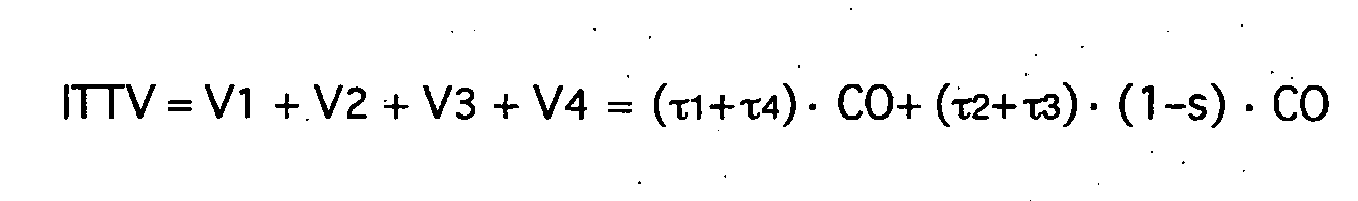
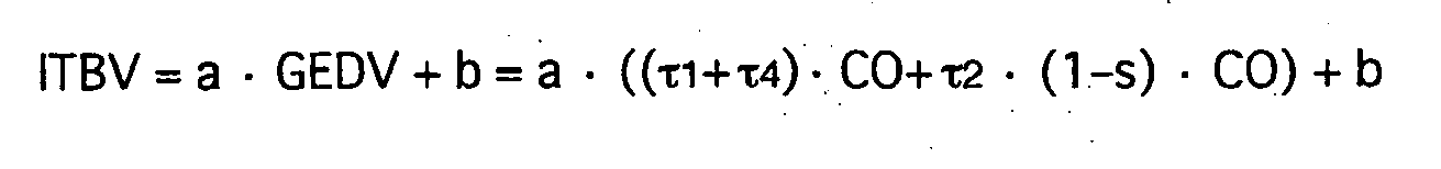
Für das rechte Atrium RA wird ein erstes ideal durchmischtes Volumen V1 mit charakteristischer Zeit τ1, für den rechten Ventrikel ein weiteres ideal durchmischtes Volumen V2 mit charakteristischer Zeit τ2, für die Gesamtheit aus pulmonalem Blutvolumen PBV und extravasalem Thermovolumen ETV ein drittes ideal durchmischtes Volumen V3 mit charakteristischer Zeit τ3 und ein Verzögerungsglied ("Delay") D3, sowie für die Gesamtheit aus linkem Atrium LA und linkem Ventrikel LV ein viertes ideal durchmischtes Volumen V4 mit charakteristischer Zeit τ4 angesetzt. Die charakteristischen Zeiten τn sind als Quotient aus dem entsprechenden Volumen Vn und dem Volumenstrom Qn durch dieses Volumen definiert.For the right atrium RA, a first ideally mixed volume V1 with characteristic time τ1, for the right ventricle another ideally mixed volume V2 with characteristic time τ2, for the whole of pulmonary blood volume PBV and extravasal thermal volume ETV a third ideally mixed volume V3 characteristic time τ3 and a delay element ("Delay") D3, as well as for the set of left atrium LA and left ventricle LV a fourth ideally mixed volume V4 with characteristic time τ4 set. The characteristic times τn are defined as the quotient of the corresponding volume Vn and the volume flow Qn by this volume.
Da sich eine lineare Verzögerung in der rechten und der linken Herzhälfte äquivalent auf die Systemantwort ("output") y auswirkt, werden entsprechende Effekte in dem Verzögerungsglied ("Delay") D0 zusammengefaßt. Das Verzögerungsglied D0 kann durch Wahl einer korrigierten Startzeit berücksichtigt werden.Since a linear delay in the right and left halves of the heart acts equivalently on the system response ("output") y, corresponding effects are summarized in the delay ("delay") D0. The delay D0 can be taken into account by selecting a corrected start time.
Für die Systemantwort ("Output") y ergibt sich: 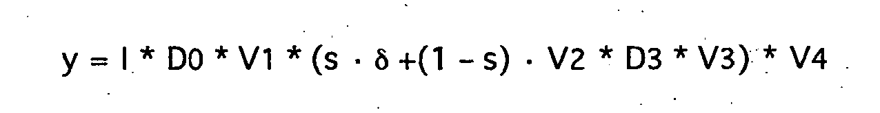
Die gemessene Dilutionskurve y, deren typischer Verlauf bei Auftreten eines Rechts-Links-Shunts in ![]()
![]()
Die Störfunktion I wird als Dirac-Stoßfunktion mit ideal kurzer Injektionszeit und Indikatormenge m betrachtet gemäß 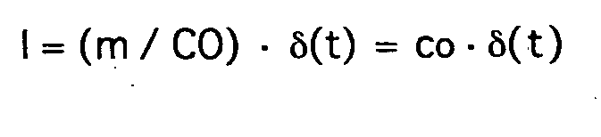
Für die Zeitkonstanten gilt ![]()
![]()
![]()
![]()

![]()
![]()
![]()
![]()
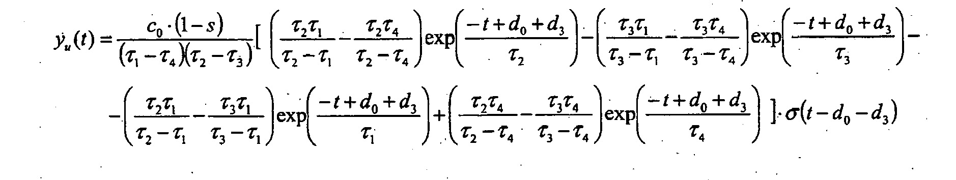
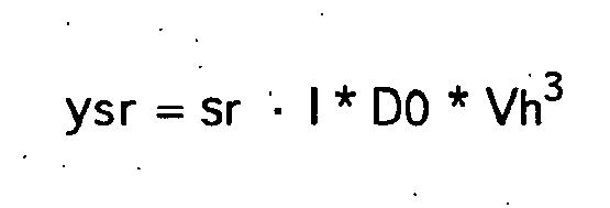
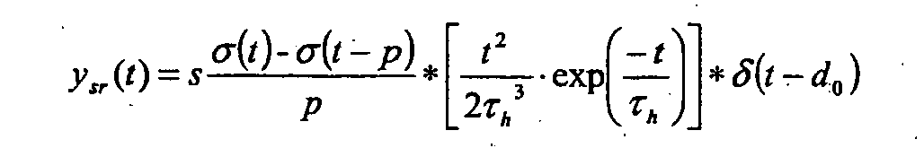
Darin bezeichnen do und d3 die den Verzögerungsgliedern D0 bzw. D3 entsprechenden charakteristischen Zeiten. Die Anfangskonzentration co kann durch Integration der Dilutionskurve ermittelt werden: ![]()
![]()
Für das größte Volumen, V3, wird die charakteristische Zeit τ3 der Zeitkonstante DST (down slope time) des exponentiellen Abfall y ∝ exp(-t/DST) der Dilutionskurve y nach dem Dilutions-Peak gleichgesetzt gemäß ![]()
![]()
Die gemäß 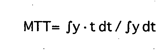
![]()
![]()
Für rechtes und linkes Atrium sowie rechten und linken Ventrikel können vereinfachend konstante Volumenverhältnisse angesetzt werden, beispielsweise ![]()
![]()
![]()
![]()
Die verbleibenden Modellparameter s, do und d3 können vorzugsweise durch einen Kurvenanpassungsalgorithmus (beispielsweise Levenberg-Marquardt-Algorithmus) bestimmt werden.The remaining model parameters s, do and d3 may preferably be determined by a curve fitting algorithm (eg Levenberg-Marquardt algorithm).
Mittels der gemäß obigen Beziehungen ermittelten Modellparameter kann die Auswerteeinheit 14 verschiedene hämodynamische Parameter mit geringeren Fehlerabweichungen berechnen, als dies nach dem Stand der Technik möglich ist:
- Herzzeitvolumen:

- pulmonales Thermovolumen:

- intrathorakales Thermovolumen:
- globales enddiastolisches Volumen:

- intrathorakales Blutvolumen:
- extravasales Lungenwasser:

- kardialer Funktionsindex:

- Cardiac Output:
- pulmonary thermal volume:
- intrathoracic thermal volume:
- global end-diastolic volume:
- intrathoracic blood volume:
- extravascular lung water:
- cardiac function index:
Die Berechnungsoperationen können vorteilhafterweise im wesentlichen wie folgt in der programmtechnischen Einrichtung der Auswerteeinheit 14 implementiert sein. Nach Abschätzung des Startpunkts der Dilutionskurve y und des Dilutions-Peaks mit geeigneten Kriterien, welche dem Stand der Technik entlehnt sein können, wird die mittlere Durchgangszeit MTT und die Abklingzeit DST berechnet. Mit einem geeigneten Algorithmus wird die Modellfunktion mit geringstmöglicher Abweichung an die meßtechnisch ermittelte Dilutionskurve angepaßt. Mit den Modellparametern aus der angepaßten Modellfunktion werden das Herzzeitvolumen CO und das Shuntverhältnis s berechnet. Anschließend können die Modellvolumina und weitere hämodynamische Parameter berechnet werden.The calculation operations can advantageously be implemented essentially as follows in the program-technical device of the
Sind die Prozessorresourcen der Auswerteeinheit 14 begrenzt, können die Berechnungsoperationen vorteilhafterweise alternativ auch im wesentlichen wie folgt in der programmtechnischen Einrichtung der Auswerteeinheit 14 implementiert sein. Nach Abschätzung des Startpunkts der Dilutionskurve y und des Dilutions-Peaks mit geeigneten Kriterien, welche dem Stand der Technik entlehnt sein können, wird die mittlere Durchgangszeit MTT und die Abklingzeit DST berechnet. Es wird ein vor dem Thermodilutions-Peak liegender Shunt-Peak ermittelt (siehe
Für gewöhnlich kann ein zusätzlicher Peak vor dem Dilutions-Peak stets als Rechts-Links-Shunt betrachtet werden. Ein Rechts-Links-Shunt-Peak kann im Extremfall gar bis etwa 150% höher als der Dilutions-Peak sein.Usually, an additional peak before the dilution peak can always be considered a right-left shunt. In extreme cases, a right-left shunt peak can even be up to about 150% higher than the dilution peak.
Ein frühzeitiges Ende des exponentiellen Abklingens, wie es in
Zur Berücksichtigung des Links-Rechts-Shunts können vorteilhafterweise prinzipiell ähnliche Berechnungsoperationen in die Auswerteeinheit 14 implementiert sein, wie für die Bestimmung des Rechts-Links-Shunts. Wie in
Für das rechte Atrium RA wird ein erstes ideal durchmischtes Volumen V1 mit charakteristischer Zeit τ1, für den rechten Ventrikel ein weiteres ideal durchmischtes Volumen V2 mit charakteristischer Zeit τ2, für die Gesamtheit aus pulmonalem Blutvolumen PBV und extravasalem Thermovolumen ETV ein drittes ideal durchmischtes Volumen V3 mit charakteristischer Zeit τ3 und ein Verzögerungsglied ("Delay") D3, sowie für die Gesamtheit aus linkem Atrium LA und linkem Ventrikel LV ein viertes ideal durchmischtes Volumen V4 mit charakteristischer Zeit τ4 angesetzt. Die charakteristischen Zeiten τn sind als Quotient aus dem entsprechenden Volumen Vn und dem Volumenstrom Qn durch dieses Volumen definiert.For the right atrium RA, a first ideally mixed volume V1 with a characteristic time τ1, for the right ventricle another ideally mixed volume V2 with a characteristic time τ2, for the whole of pulmonary Blood volume PBV and extravascular thermovolume ETV a third ideally mixed volume V3 with characteristic time τ3 and a delay D3, and for the set of left atrium LA and left ventricle LV a fourth ideally mixed volume V4 with characteristic time τ4. The characteristic times τn are defined as the quotient of the corresponding volume Vn and the volume flow Qn by this volume.
Da sich eine lineare Verzögerung in der rechten und der linken Herzhälfte äquivalent auf die Systemantwort ("Output") y auswirkt, werden entsprechende Effekte in dem Verzögerungsglied ("Delay") D0 zusammengefaßt. Das Verzögerungsglied D0 kann durch Wahl einer korrigierten Startzeit berücksichtigt werden.Since a linear delay in the right and left halves of the heart is equivalent to the system response ("output") y, corresponding effects are summarized in the delay D0. The delay D0 can be taken into account by selecting a corrected start time.
Für die Systemantwort ("Output") y ergibt sich: 
In erster Näherung kann die Stör- bzw. Eingangsfunktion ("Input") I als Dirac-Stoßfunktion δ, d.h. mit verschwindender Dauer betrachtet werden. Üblicherweise dauert eine Injektion jedoch etwa zwei Sekunden. Bei der Shunt-Berechnung kann dies zu einem beachtenswerten Fehler führen. Alternativ besteht daher erfindungsgemäß die Möglichkeit, für die Störfunktion I einen konstanten Fluß 1/p während der Injektionsdauer p anzunehmen, und somit die Störfunktion I als Differenz zweier Heavyside-Sprungfunktionen anzusetzen gemäß 
Gemäß einer vorteilhaften Weiterbildung der Erfindung kann mit einem erweiterten Modell und mehrdimensionaler Kurvenanpassung Links-Rechts-Shunt und Rechts-Links-Shunt simultan berücksichtigt und zudem vorzugsweise noch die Rezirkulation durch den Körperkreislauf 9 berücksichtigt werden. Das zugehörige Schaltbild ist in
Angesetzt werden für das rechte Atrium RA ein erstes ideal durchmischtes Volumen V1 mit charakteristischer Zeit τ1, für den rechten Ventrikel ein weiteres ideal durchmischtes Volumen V2 mit charakteristischer Zeit τ2, für die Gesamtheit aus pulmonalem Blutvolumen PBV und extravasalem Thermovolumen ETV ein drittes ideal durchmischtes Volumen V3 mit charakteristischer Zeit τ3 und ein Verzögerungsglied ("Delay") D3 mit charakteristischer Zeit d3, für das linke Atrium LA ein viertes ideal durchmischtes Volumen V4 mit charakteristischer Zeit τ4, und für den linken Ventrikel LV ein fünftes ideal durchmischtes Volumen V5 mit charakteristischer Zeit τ5. Die charakteristischen Zeiten τn sind wiederum als Quotient aus dem entsprechenden Volumen Vn und dem Volumenstrom Qn durch dieses Volumen definiert.For the right atrium RA, a first ideally mixed volume V1 with characteristic time τ1, for the right ventricle another ideally mixed volume V2 with characteristic time τ2, for the whole of pulmonary blood volume PBV and extravascular thermovolume ETV a third ideally mixed volume V3 are set up with characteristic time τ3 and a delay element D3 with characteristic time d3, for the left atrium LA a fourth ideally mixed volume V4 with characteristic time τ4, and for the left ventricle LV a fifth ideally mixed volume V5 with characteristic time τ5 , The characteristic times τn are again defined as the quotient of the corresponding volume Vn and the volume flow Qn through this volume.
Verzögerungsanteile in der rechten und der linken Herzhälfte werden wiederum Effekte in dem Verzögerungsglied ("Delay") D0 zusammengefaßt, welches durch Wahl einer korrigierten Startzeit berücksichtigt werden kann.Delay components in the right and left halves of the heart are in turn combined into effects in the delay D0, which can be taken into account by selecting a corrected start time.
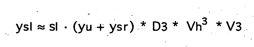
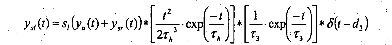
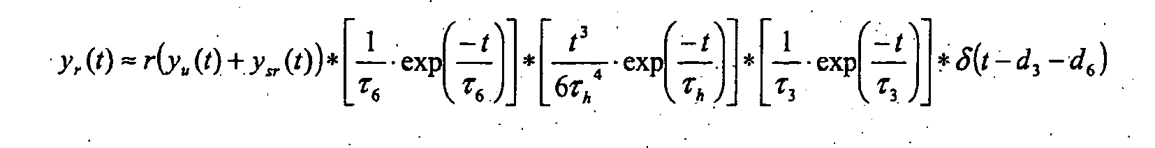
Der Links-Rechts-Shunt mit Shunt-Verhältnis sl ist in umgekehrter Flußrichtung parallel zu rechtem Ventrikel RV, pulmonalem Blutvolumen PBV, linkem Atrium LA und linkem Ventrikel LV geschaltet. Der Rechts-Links-Shunt mit Shunt-Verhältnis sr ist parallel zu rechtem Ventrikel RV und pulmonalem Blutvolumen PBV geschaltet. Betreffend die Rezirkulation r wird ein ideal durchmischtes Volumen V6 mit charakteristischer Zeit τ6 für das systemische Blutvolumen SBV und ein Verzögerungsglied ("Delay") D3 mit charakteristischer Zeit d3 angesetzt.The left-right shunt with shunt ratio sl is connected in the reverse flow direction parallel to the right ventricle RV, pulmonary blood volume PBV, left atrium LA and left ventricle LV. The right-left shunt with shunt ratio sr is connected in parallel with right ventricle RV and pulmonary blood volume PBV. Concerning the recirculation r, an ideally mixed volume V6 with a characteristic time τ6 for the systemic blood volume SBV and a delay element (D3) with a characteristic time d3 is set.
Für die Systemantwort y ergibt sich: 
![]()
![]()
Die mittlere Durchgangszeit entspricht wieder der Summe der Zeitkonstanten der Reihenschaltung: ![]()
![]()
Wenn alle Volumina des Herzens gleich Vh gesetzt werden und nur der erste Rezirkulationsdurchgang berücksichtigt wird, ergibt sich: 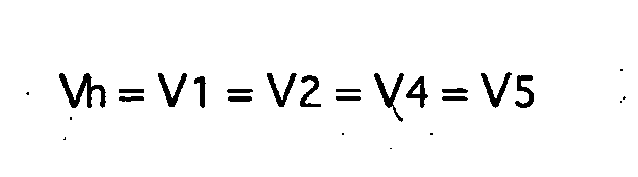

Allgemein können, wie oben erwähnt, auch nicht-diffusible intravasale Indikatoren, wie z.B. LiCI oder ICG verwendet werden. Bei Verwenung nicht-diffusibler intravasaler Indikatoren können Herzzeitvolumen (Cardiac Output - CO) und globales enddiastolisches Volumen (GEDV) bestimmt werden, nicht jedoch extravasales Lungenwasser (EVLW). Die Algorithmen können dabei prinzipiell gegenüber den obenbeschriebenen Algorithmen unverändert bleiben mit der Ausnahme, daß dann das größte intrathorakale Ausbreitungsvolumen dem intrathorakalen Blutvolumen ITBV (bei LiCI- oder ICG-Indikator) anstatt dem intrathorakalen Thermovolumen ITTV (bei Kälteindikator) entspricht.Generally, as mentioned above, non-diffusible intravascular indicators such as LiCI or ICG may also be used. Using non-diffusible intravascular indicators, Cardiac Output ( CO) and Global End-Diastolic Volume (GEDV) can be determined but not extravascular lung water (EVLW). The algorithms can in principle remain unchanged from the algorithms described above, with the exception that the greatest intrathoracic propagation volume corresponds to the intrathoracic blood volume ITBV (in the case of the LiCI or ICG indicator) instead of the intrathoracic thermal volume ITTV (in the case of the cold indicator).
Claims (22)
- Device for determining at least one hemodynamic parameter of a living being, which has the following:- an extracardial effect unit having means for introducing a disruption that can be characterized by means of a disruption function I into the cardiovascular system of the living being, by means of a defined effect on venous blood,- a sensor device (13) for producing a measurement signal as a function of a physical variable of arterial blood, which characterizes a system response of the cardiovascular system brought about by the disruption function, and- an evaluation unit (14) that has an input channel for continuously reading in the measurement signal,wherein the evaluation unit (14) is set up, in terms of program technology, to calculate the hemodynamic parameter from a dilution curve y that corresponds to the time progression of the measurement signal and, in this connection, to take into consideration a possible short-circuit current from the right to the left half of the heart (RL shunt) and/or from the left to the right half of the heart (LR shunt) of the living being,
characterized in that for calculating the hemodynamic parameter, a model for the cardiovascular and pulmonary circulation system of the living being is used as the basis that comprises a serial circuit of several system elements and at least one system element connected in parallel, for taking the short-circuit current into consideration, and the program technology set-up of the evaluation unit (14) comprises calculation operations that can be derived from a model function for the system response that corresponds to this model and that comprises the mathematical convolution of terms that incorporate the system elements connected in series and the disruption function,
wherein the terms each have a characteristic time as a model parameter, and in the underlying model,- a first ideally mixed volume for the right atrium RA (2) of the living being,- a second ideally mixed volume for the right ventricle RV (3) of the living being,- a third ideally mixed volume for the totality of pulmonary blood volume PBV and extravasal thermal volume ETV of the living being and a delay element, and- at least a fourth ideally mixed volume for the totality of the left atrium (6) and the left ventricle LV (7) of the living beingare assumed as system elements of the serial circuit. - Device according to claim 1, wherein the program technology set-up of the evaluation unit (14) has operations for calculating at least one of the following variables as a hemodynamic parameter:- cardiac output CO,- pulmonary thermal volume PTV,- intrathoracic thermal volume ITTV,- global end-diastolic volume GEDV,- intrathoracic blood volume ITBV,- extravasal lung water EVLW,- cardiac function index CFI.
- Device according to any of the preceding claims, wherein the program technology set-up of the evaluation unit (14) has operations for estimating a starting point of the dilution curve y and operations for determining a mean transit time MTT according to
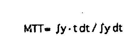
with the time t from the dilution curve y,
and wherein the mean transit time MTT is taken into consideration in the program technology set-up as the sum of the characteristic times of the first, second, third, and fourth ideally mixed volumes as well as of the delay element. - Device according to any of the preceding claims, wherein the program technology set-up of the evaluation unit (14) has operations for recognizing a dilution peak and operations for determining an exponential decay time DST from an exponential drop of the dilution curve y after the dilution peak, according to

with the time t,
and wherein the exponential decay time DST is taken into consideration in the program technology set-up as a characteristic time of the third ideally mixed volume. - Device according to any of the preceding claims, wherein a constant ratio of the characteristic times of the first, second, and fourth ideally mixed volumes relative to one another is provided in the program technology set-up of the evaluation unit (14).
- Device according to any of the preceding claims, wherein the program technology set-up of the evaluation unit (14) has operations for determining the characteristic times by means of fitting, by calculations, of a model curve that corresponds to one of the model functions to the dilution curve y.
- Device according to claim 6, wherein the fitting, by calculations, of the model curve corresponding to the model function to the dilution curve y is implemented by means of a Levenberg-Marquardt algorithm.
- Device according to any of the preceding claims, wherein the program technology set-up of the evaluation unit (14) has operations for determining a short-circuit peak as an additional peak of the dilution curve y ahead of the dilution peak, and the case of the non-existence of a short-circuit peak is provided as a condition for the non-existence of a short-circuit current from the right atrium (2) to the left ventricle (7) of the living being.
- Device according to claim 8, wherein the program technology set-up of the evaluation unit (14) has operations for determining a tangent to the dilution curve y below the short-circuit peak, which encloses the greatest possible area with the dilution curve y.
- Device according to any of the preceding claims, wherein the program technology set-up of the evaluation unit (14) has operations for determining the value of the dilution curve y at the end of an exponential drop of the dilution curve y after the dilution peak,
and the case that the value determined exceeds a predetermined proportion of the value of the dilution curve y at the dilution peak is provided as a condition for the existence of a short-circuit current from the left ventricle to the right ventricle of the living being. - Device according to claim 10, wherein the predetermined proportion is at least 30 percent.
- Device according to any of the preceding claims, wherein a Dirac function having the form

is assumed for the disruption function in the program technology set-up of the evaluation unit (14),
wherein δ is the Dirac delta function and co is a coefficient. - Device according to claim 12, wherein the coefficient co is assumed to be a quotient of an indicator quantity m and a cardiac output CO of the living being according to

- Device according to any of claims 12-13, wherein the program technology set-up of the evaluation unit (14) has operations for determining the coefficient co as an integral of the dilution curve y over the time t, according to

- Device according to any of the preceding claims, wherein the difference between two step functions is assumed for the disruption function, according to

wherein σ is the Heaviside step function and p is the duration of the defined effect on central vein blood. - Device according to any of the preceding claims, wherein the extracardial effect unit is a central venous catheter unit (11).
- Device according to one of the preceding claims, comprising an arterial catheter unit (12) that is equipped with the sensor device (13).
- Device according to one of the preceding claims, wherein the means for introducing the disruption are means for bringing about a temperature change in venous blood, and the physical variable that characterizes the system response of the blood circulation is a temperature of arterial blood.
- Device according to claim 18, wherein the means for introducing the disruption comprise heating means for giving off a temperature impulse to central-venous blood.
- Device according to claim 18, wherein the means for introducing a disruption in the blood circulation comprise means for injecting a cooled bolus into venous blood.
- Device according to any of claims 1-17, wherein the means for introducing a disruption comprise means for injecting an indicator into venous blood, and the physical variable that characterizes the system response of the blood circulation is an indicator concentration in arterial blood.
- Device according to any of the preceding claims, furthermore comprising a control unit for controlling the means for introducing a disruption into the blood circulation.
Applications Claiming Priority (2)
| Application Number | Priority Date | Filing Date | Title |
|---|---|---|---|
| DE102005007592A DE102005007592A1 (en) | 2005-02-18 | 2005-02-18 | Device for the determination of cardiopulmonary volumes and flows of a living being |
| PCT/EP2006/050006 WO2006087245A1 (en) | 2005-02-18 | 2006-01-03 | Device for determining cardiopulmonary volumes and flows of a living being |
Publications (2)
| Publication Number | Publication Date |
|---|---|
| EP1848329A1 EP1848329A1 (en) | 2007-10-31 |
| EP1848329B1 true EP1848329B1 (en) | 2011-03-23 |
Family
ID=36031624
Family Applications (1)
| Application Number | Title | Priority Date | Filing Date |
|---|---|---|---|
| EP06700675A Expired - Lifetime EP1848329B1 (en) | 2005-02-18 | 2006-01-03 | Device for determining cardiopulmonary volumes and flows of a living being |
Country Status (6)
| Country | Link |
|---|---|
| US (1) | US8257273B2 (en) |
| EP (1) | EP1848329B1 (en) |
| JP (1) | JP4881324B2 (en) |
| DE (3) | DE102005007592A1 (en) |
| ES (1) | ES2361179T3 (en) |
| WO (1) | WO2006087245A1 (en) |
Families Citing this family (8)
| Publication number | Priority date | Publication date | Assignee | Title |
|---|---|---|---|---|
| US20070093697A1 (en) * | 2005-10-21 | 2007-04-26 | Theranova, Llc | Method and apparatus for detection of right to left shunting in the cardiopulmonary vasculature |
| DE102006028533A1 (en) * | 2006-06-21 | 2008-01-03 | Iprm Intellectual Property Rights Management Ag | Apparatus and computer program for determining a pulmonary condition of a patient represented by a cardiopulmonary blood volume |
| DE102007049409C5 (en) * | 2007-10-15 | 2020-04-09 | Edwards Lifesciences Iprm Ag | Method and device for indicator dilution measurements |
| US20100016731A1 (en) * | 2008-07-15 | 2010-01-21 | Cardiox Corporation | Hemodynamic Detection of Circulatory Anomalies |
| WO2011079863A1 (en) * | 2009-12-30 | 2011-07-07 | Pulsion Medical Systems Ag | Apparatus and method for determining a volume amount of a physiological volume |
| US20130317378A1 (en) * | 2012-05-25 | 2013-11-28 | Nikolai M. Krivitski | Assessment of Pulmonary Blood Flow and Systemic Blood Flow in a Single Ventricle Patient |
| US10405757B2 (en) | 2014-02-25 | 2019-09-10 | Icu Medical, Inc. | Patient monitoring system with gatekeeper signal |
| AU2016341195B2 (en) | 2015-10-19 | 2019-03-14 | Icu Medical, Inc. | Hemodynamic monitoring system with detachable display unit |
Family Cites Families (8)
| Publication number | Priority date | Publication date | Assignee | Title |
|---|---|---|---|---|
| IL95743A (en) * | 1990-09-19 | 1993-02-21 | Univ Ramot | Method of measuring blood flow |
| DE4214402C2 (en) * | 1992-04-30 | 1997-04-24 | Pulsion Verwaltungs Gmbh & Co | Device for determining the filling status of a blood circulation |
| US5595181A (en) * | 1994-03-24 | 1997-01-21 | Hubbard; A. Robert | System for providing cardiac output and shunt quantitation |
| SE9602388D0 (en) * | 1996-06-17 | 1996-06-17 | Jiri Endrys | An apparatus for detecting and determining the magnitude of intracardiac shunts |
| US6055985A (en) * | 1999-04-09 | 2000-05-02 | B.H.B., L.C. | Methods for injecting a contrast medium to generate prolonged uniform vascular enhancement |
| ES2218248T3 (en) * | 1999-10-28 | 2004-11-16 | Pulsion Medical Systems Ag | APPARATUS, INFORMATIC SYSTEM AND INFORMATIC PROGRAM TO DETERMINE A CARDIOVASCULAR PARAMETER. |
| US6672172B2 (en) * | 2000-01-31 | 2004-01-06 | Radi Medical Systems Ab | Triggered flow measurement |
| DE60103360T2 (en) * | 2001-03-01 | 2005-06-02 | Pulsion Medical Systems Ag | Device, computer program and central vein catheter for hemodynamic monitoring |
-
2005
- 2005-02-18 DE DE102005007592A patent/DE102005007592A1/en not_active Withdrawn
-
2006
- 2006-01-03 US US11/884,318 patent/US8257273B2/en not_active Expired - Fee Related
- 2006-01-03 DE DE502006009157T patent/DE502006009157D1/en not_active Expired - Lifetime
- 2006-01-03 JP JP2007555559A patent/JP4881324B2/en not_active Expired - Fee Related
- 2006-01-03 ES ES06700675T patent/ES2361179T3/en not_active Expired - Lifetime
- 2006-01-03 EP EP06700675A patent/EP1848329B1/en not_active Expired - Lifetime
- 2006-01-03 WO PCT/EP2006/050006 patent/WO2006087245A1/en not_active Ceased
- 2006-01-03 DE DE202006020941U patent/DE202006020941U1/en not_active Expired - Lifetime
Also Published As
| Publication number | Publication date |
|---|---|
| DE102005007592A1 (en) | 2006-08-24 |
| JP4881324B2 (en) | 2012-02-22 |
| US20080146945A1 (en) | 2008-06-19 |
| DE502006009157D1 (en) | 2011-05-05 |
| US8257273B2 (en) | 2012-09-04 |
| JP2008529695A (en) | 2008-08-07 |
| DE202006020941U1 (en) | 2011-03-03 |
| WO2006087245A1 (en) | 2006-08-24 |
| EP1848329A1 (en) | 2007-10-31 |
| ES2361179T3 (en) | 2011-06-14 |
Similar Documents
| Publication | Publication Date | Title |
|---|---|---|
| EP1813188B1 (en) | System for providing a dilution measuring point | |
| DE69919347T2 (en) | SYSTEM FOR FLOW MEASUREMENT IN TIGHT CHANNELS CONTAINS A TEMPERATURE AND A PRESSURE SENSOR | |
| EP2470913B1 (en) | Calibration method for prospective calibration of a measuring device, computer program and measuring device | |
| DE60110281T2 (en) | Triggering a flow measurement | |
| DE69731943T2 (en) | DEVICE FOR DETERMINING THE BLOOD RECIRCULATION IN A VASCULAR ACCESS | |
| DE102011114666A1 (en) | Device for hemodynamic monitoring | |
| DE102009023965A1 (en) | Respiratory device for pressure-supporting ventilation of patient, has control and evaluation unit analyzing functional dependency of pressure and respiratory volume, where elastance or compliance is determined from rise of pressure | |
| DE3856390T2 (en) | Device for measuring cardiac output | |
| DE102012109282A1 (en) | Technology for automatic access to a vessel and device based on real-time ultrasound volumetry | |
| EP1848329B1 (en) | Device for determining cardiopulmonary volumes and flows of a living being | |
| EP3145394B1 (en) | Method and device for determining central systolic blood pressure | |
| EP2908720B1 (en) | Device and method for detecting and signalling a stress state of a person | |
| DE602004007238T2 (en) | Device, computer system and computer program for determining intrathoracic blood volume and other cardiovascular parameters | |
| DE4130931C2 (en) | Method and device for determining the circulating blood volume | |
| EP3093678A1 (en) | Method for optimizing prediction of bolus arrival time using mri for diagnostic imaging | |
| DE2821037B2 (en) | Device for determining the systolic, diastolic and venous values of blood pressure | |
| DE3786491T2 (en) | Device for deriving the minute volume of the right ventricle from temperature dilution curves of high reproduction quality. | |
| DE102010015664A1 (en) | Method and device for determining the fistula flow of a fistula for dialysis treatment | |
| DE102005059520A1 (en) | Dilution device and computer program | |
| EP3557277B1 (en) | Method for monitoring movement information of a patient in a magnetic resonance device, magnetic resonance device, computer program and electronically readable data carrier | |
| DE2819128A1 (en) | Blood flow determination process through vessels - adds fluid altering electrical conductivity and measures conductivity using HF | |
| DE2509616C3 (en) | Direct-display device for determining cardiac output using the thermodilution method | |
| EP3305345B1 (en) | Device for recirculation measurement | |
| DE102008060049A1 (en) | Method for determining a coding for a flow measurement and method for flow measurement and correspondingly designed magnetic resonance system | |
| DE102007050598A1 (en) | Movable long-term blood pressure meter for measuring systolic blood pressure, has microprocessor for activating blood pressure measurement and for outputting activation signal in response to determined process of pulse wave signal |
Legal Events
| Date | Code | Title | Description |
|---|---|---|---|
| PUAI | Public reference made under article 153(3) epc to a published international application that has entered the european phase |
Free format text: ORIGINAL CODE: 0009012 |
|
| 17P | Request for examination filed |
Effective date: 20070629 |
|
| AK | Designated contracting states |
Kind code of ref document: A1 Designated state(s): DE ES FR GB IT |
|
| 17Q | First examination report despatched |
Effective date: 20080115 |
|
| 19A | Proceedings stayed before grant |
Effective date: 20080107 |
|
| 19F | Resumption of proceedings before grant (after stay of proceedings) |
Effective date: 20090601 |
|
| GRAP | Despatch of communication of intention to grant a patent |
Free format text: ORIGINAL CODE: EPIDOSNIGR1 |
|
| DAX | Request for extension of the european patent (deleted) | ||
| RBV | Designated contracting states (corrected) |
Designated state(s): DE ES FR GB IT |
|
| GRAS | Grant fee paid |
Free format text: ORIGINAL CODE: EPIDOSNIGR3 |
|
| REG | Reference to a national code |
Ref country code: DE Ref legal event code: R138 Ref document number: 202006020941 Country of ref document: DE Free format text: GERMAN DOCUMENT NUMBER IS 502006009157 Ref country code: DE Ref legal event code: R138 Ref document number: 502006009157 Country of ref document: DE Free format text: GERMAN DOCUMENT NUMBER IS 502006009157 |
|
| GRAA | (expected) grant |
Free format text: ORIGINAL CODE: 0009210 |
|
| AK | Designated contracting states |
Kind code of ref document: B1 Designated state(s): DE ES FR GB IT |
|
| REG | Reference to a national code |
Ref country code: GB Ref legal event code: FG4D Free format text: NOT ENGLISH |
|
| REF | Corresponds to: |
Ref document number: 502006009157 Country of ref document: DE Date of ref document: 20110505 Kind code of ref document: P |
|
| REG | Reference to a national code |
Ref country code: DE Ref legal event code: R096 Ref document number: 502006009157 Country of ref document: DE Effective date: 20110505 |
|
| REG | Reference to a national code |
Ref country code: ES Ref legal event code: FG2A Ref document number: 2361179 Country of ref document: ES Kind code of ref document: T3 Effective date: 20110614 |
|
| PLBE | No opposition filed within time limit |
Free format text: ORIGINAL CODE: 0009261 |
|
| STAA | Information on the status of an ep patent application or granted ep patent |
Free format text: STATUS: NO OPPOSITION FILED WITHIN TIME LIMIT |
|
| 26N | No opposition filed |
Effective date: 20111227 |
|
| REG | Reference to a national code |
Ref country code: DE Ref legal event code: R097 Ref document number: 502006009157 Country of ref document: DE Effective date: 20111227 |
|
| PGFP | Annual fee paid to national office [announced via postgrant information from national office to epo] |
Ref country code: ES Payment date: 20140122 Year of fee payment: 9 Ref country code: IT Payment date: 20140129 Year of fee payment: 9 Ref country code: FR Payment date: 20140124 Year of fee payment: 9 |
|
| PGFP | Annual fee paid to national office [announced via postgrant information from national office to epo] |
Ref country code: GB Payment date: 20140123 Year of fee payment: 9 |
|
| GBPC | Gb: european patent ceased through non-payment of renewal fee |
Effective date: 20150103 |
|
| PG25 | Lapsed in a contracting state [announced via postgrant information from national office to epo] |
Ref country code: GB Free format text: LAPSE BECAUSE OF NON-PAYMENT OF DUE FEES Effective date: 20150103 |
|
| REG | Reference to a national code |
Ref country code: FR Ref legal event code: ST Effective date: 20150930 |
|
| PG25 | Lapsed in a contracting state [announced via postgrant information from national office to epo] |
Ref country code: FR Free format text: LAPSE BECAUSE OF NON-PAYMENT OF DUE FEES Effective date: 20150202 |
|
| PG25 | Lapsed in a contracting state [announced via postgrant information from national office to epo] |
Ref country code: IT Free format text: LAPSE BECAUSE OF NON-PAYMENT OF DUE FEES Effective date: 20150103 |
|
| REG | Reference to a national code |
Ref country code: ES Ref legal event code: FD2A Effective date: 20160226 |
|
| PG25 | Lapsed in a contracting state [announced via postgrant information from national office to epo] |
Ref country code: ES Free format text: LAPSE BECAUSE OF NON-PAYMENT OF DUE FEES Effective date: 20150104 |
|
| PGFP | Annual fee paid to national office [announced via postgrant information from national office to epo] |
Ref country code: DE Payment date: 20190320 Year of fee payment: 14 |
|
| REG | Reference to a national code |
Ref country code: DE Ref legal event code: R119 Ref document number: 502006009157 Country of ref document: DE |
|
| PG25 | Lapsed in a contracting state [announced via postgrant information from national office to epo] |
Ref country code: DE Free format text: LAPSE BECAUSE OF NON-PAYMENT OF DUE FEES Effective date: 20200801 |