EP1845849B1 - Lower extremity exoskeleton - Google Patents
Lower extremity exoskeleton Download PDFInfo
- Publication number
- EP1845849B1 EP1845849B1 EP06733769.1A EP06733769A EP1845849B1 EP 1845849 B1 EP1845849 B1 EP 1845849B1 EP 06733769 A EP06733769 A EP 06733769A EP 1845849 B1 EP1845849 B1 EP 1845849B1
- Authority
- EP
- European Patent Office
- Prior art keywords
- exoskeleton
- flexion
- person
- foot
- leg
- Prior art date
- Legal status (The legal status is an assumption and is not a legal conclusion. Google has not performed a legal analysis and makes no representation as to the accuracy of the status listed.)
- Expired - Lifetime
Links
Images


Classifications
-
- A—HUMAN NECESSITIES
- A61—MEDICAL OR VETERINARY SCIENCE; HYGIENE
- A61B—DIAGNOSIS; SURGERY; IDENTIFICATION
- A61B5/00—Measuring for diagnostic purposes; Identification of persons
- A61B5/103—Measuring devices for testing the shape, pattern, colour, size or movement of the body or parts thereof, for diagnostic purposes
- A61B5/1036—Measuring load distribution, e.g. podologic studies
- A61B5/1038—Measuring plantar pressure during gait
-
- A—HUMAN NECESSITIES
- A61—MEDICAL OR VETERINARY SCIENCE; HYGIENE
- A61B—DIAGNOSIS; SURGERY; IDENTIFICATION
- A61B5/00—Measuring for diagnostic purposes; Identification of persons
- A61B5/45—For evaluating or diagnosing the musculoskeletal system or teeth
- A61B5/4528—Joints
-
- A—HUMAN NECESSITIES
- A61—MEDICAL OR VETERINARY SCIENCE; HYGIENE
- A61B—DIAGNOSIS; SURGERY; IDENTIFICATION
- A61B5/00—Measuring for diagnostic purposes; Identification of persons
- A61B5/68—Arrangements of detecting, measuring or recording means, e.g. sensors, in relation to patient
- A61B5/6801—Arrangements of detecting, measuring or recording means, e.g. sensors, in relation to patient specially adapted to be attached to or worn on the body surface
- A61B5/6813—Specially adapted to be attached to a specific body part
- A61B5/6829—Foot or ankle
-
- A—HUMAN NECESSITIES
- A61—MEDICAL OR VETERINARY SCIENCE; HYGIENE
- A61F—FILTERS IMPLANTABLE INTO BLOOD VESSELS; PROSTHESES; DEVICES PROVIDING PATENCY TO, OR PREVENTING COLLAPSING OF, TUBULAR STRUCTURES OF THE BODY, e.g. STENTS; ORTHOPAEDIC, NURSING OR CONTRACEPTIVE DEVICES; FOMENTATION; TREATMENT OR PROTECTION OF EYES OR EARS; BANDAGES, DRESSINGS OR ABSORBENT PADS; FIRST-AID KITS
- A61F5/00—Orthopaedic methods or devices for non-surgical treatment of bones or joints; Nursing devices ; Anti-rape devices
- A61F5/01—Orthopaedic devices, e.g. long-term immobilising or pressure directing devices for treating broken or deformed bones such as splints, casts or braces
- A61F5/0102—Orthopaedic devices, e.g. long-term immobilising or pressure directing devices for treating broken or deformed bones such as splints, casts or braces specially adapted for correcting deformities of the limbs or for supporting them; Ortheses, e.g. with articulations
-
- B—PERFORMING OPERATIONS; TRANSPORTING
- B25—HAND TOOLS; PORTABLE POWER-DRIVEN TOOLS; MANIPULATORS
- B25J—MANIPULATORS; CHAMBERS PROVIDED WITH MANIPULATION DEVICES
- B25J9/00—Programme-controlled manipulators
- B25J9/0006—Exoskeletons, i.e. resembling a human figure
-
- A—HUMAN NECESSITIES
- A61—MEDICAL OR VETERINARY SCIENCE; HYGIENE
- A61B—DIAGNOSIS; SURGERY; IDENTIFICATION
- A61B2562/00—Details of sensors; Constructional details of sensor housings or probes; Accessories for sensors
- A61B2562/02—Details of sensors specially adapted for in-vivo measurements
- A61B2562/0219—Inertial sensors, e.g. accelerometers, gyroscopes, tilt switches
Definitions
- the present application relates generally to the field of lower extremity exoskeletons and more specifically to the field of low power lower extremity exoskeletons.
- US 5 476 441 A discloses a controlled-brake orthosis for providing controlled limb movement.
- the orthosis includes a stimulator for stimulating an individual's leg muscles which causes the legs to move.
- the orthosis is worn on the legs to support the legs and includes lower links rotatably coupled to upper links with lower rotatable joints.
- Brackets are rotatably coupled to the upper links with upper rotatable joints.
- the joints are located adjacent to the hip and knee joints of the individual and brakes are coupled to the joints for controlling the rotation of the joints.
- a second aspect of the present invention there is provided the lower extremity exoskeleton of claim 2.
- a lower extremity exoskeleton is configurable to be coupled to a person.
- the lower extremity exoskeleton comprises two leg supports configurable to be coupled to the person's lower limbs and configured to rest on the ground during their stance phases.
- Each leg support comprises a thigh link, a shank link, and two knee joints.
- Each knee joint is configured to allow flexion and extension between the respective shank link and the respective thigh link.
- the lower extremity exoskeleton also comprises an exoskeleton trunk configurable to be coupled to the person's upper body.
- the exoskeleton trunk is rotatably connectable to the thigh links of the leg supports allowing for the flexion and extension between the leg supports and the exoskeleton trunk.
- the energy required for flexion and extension movement between the shank link and the respective thigh link of a leg support over a cyclic knee motion is provided by the person.
- FIGS 1 and 2 are front view and rear view perspective drawings illustrating a lower extremity exoskeleton 100 .
- Lower extremity exoskeleton 100 is configurable to be coupled to a person 187 .
- Lower extremity exoskeleton 100 comprises two leg supports 101 and 102 which are configurable to be coupled to the person's lower limbs and configured to rest on the ground during the stance phase of each leg support.
- the leg supports comprise thigh links 103 and 104 and shank links 105 and 106 .
- Two knee joints 107 and 108 are configured to allow flexion and extension (shown by arrows 213 and 214 respectively) between the shank link and the thigh link of leg supports 101 and 102 .
- Lower extremity exoskeleton 100 further comprises an exoskeleton trunk 109.
- Exoskeleton trunk 109 comprises a human interface device 150 .
- Exoskeleton trunk 109 is configurable to be coupled to the person's upper body through human interface device 150 .
- the person's upper body means any location above the thighs.
- Exoskeleton trunk 109 is rotatably connectable to thigh links 103 and 104 of leg supports 101 and 102 at hip flexion-extension joints 125 and 126 , allowing for the hip flexion and extension rotations (shown by arrows 215 and 216 respectively) of leg supports 101 and 102 about hip flexion-extension axes 151 and 152 respectively.
- a cyclic knee motion here is defined as a motion where the initial and the final configurations of a shank link ( 105 or 106 ) and its corresponding thigh link ( 103 or 104 ) with respect to each other are nearly identical.
- a cyclic knee motion is a motion where the leg support is not in contact with the ground and the initial and the final configurations of the corresponding shank link and thigh link with respect to each other are nearly identical.
- a cyclic knee motion is a motion where the leg support is in contact with the ground and the initial and the final configurations of the corresponding shank link and thigh link with respect to each other are nearly identical.
- the torque required for flexion or extension between shank link ( 105 or 106 ) and the corresponding thigh link ( 103 and 104 ) is provided by person 187 .
- a power source may be used in lower extremity exoskeleton 100 to provide power for sensors, computers and other components, but does not provide energy for flexion and extension motion between the shank links the thigh links.
- power source we mean any system that produces power such as batteries, compressed gas, air compressors, hydraulic compressors, combustion engines, solar cells, and the like.
- each said leg support is configured to allow flexion of the respective knee joint during the swing phase, and to resist flexion of the respective knee joint during the stance phase to allow the transfer of a force to the ground.
- leg supports 101 and 102 comprise shank holding devices 137 and 138 that couple person 187 to leg supports 101 and 102 .
- cyclic hip motion here is defined as a motion where the initial and the final configurations of a thigh link ( 103 or 104 ) with respect to exoskeleton trunk 109 are nearly identical.
- exoskeleton trunk 109 includes two hip links 114 and 115 rotatably connectable to thigh links 103 and 104 at hip flexion-extension joints 125 and 126 , allowing for the flexion and extension of leg supports 101 and 102 about hip flexion-extension axes 151 and 152 respectively.
- hip links 114 and 115 are rotatably connected to each other at abduction-adduction joint 113 allowing for abduction and/or adduction of leg supports 101 and 102.
- Abduction and adduction of leg supports 101 and 102 are shown by arrows 217 and 218 respectively.
- exoskeleton trunk 109 is configured to hold a rear load 118 behind person 187 .
- rear load 118 is held by hip links 114 and 115 .
- exoskeleton trunk 109 further comprises extension frames 119 and 120 configured to hold a front load 154 in front of person 187 .
- extension frames 119 and 120 are connectable to hip links 114 and 115 .
- rear load 118 and front load 154 include without limitation, backpack, baby carrier, food containers, sacks, water jugs, tool boxes, barrels, ammunition, weaponry, bedding, first aid supplies, golf bags, mail bags, camera, leaf blower, compressor, electromechanical machineries and combinations thereof.
- rear load 118 and/or front load 154 are another person being carried by person 187 .
- exoskeleton trunk 109 supports a portion of the weight of person 187 through human interface device 150 .
- exoskeleton trunk 109 further comprises a hip resilient element 116 configured to apply a torque between hip links 114 and 115 .
- a hip resilient element include, without limitation, extension spring, compression spring, leaf spring, gas spring, air spring, rubber, elastomer, surgical tube, bungee cord and combinations thereof.
- the stiffness of hip resilient element 116 may be chosen such that its force generally holds up the weight of the leg supports 101 or 102 during swing phase.
- Some examples may also include a hip abduction stop 211 which limits the abduction of hip links 114 and 115 with respect to each other.
- abduction stop 211 is created using a wire rope. Wire rope 211 limits the abduction of leg supports 101 and 102 but allows adduction of leg supports 101 and 102 .
- Figure 4 is a perspective drawing where exoskeleton trunk 109 includes two hip links 114 and 115 rotatably connectable to thigh links 103 and 104 allowing for flexion and extension of support legs 101 and 102 relative to exoskeleton trunk 109 , wherein hip links 114 and 115 are compliantly connected to each other allowing for abduction and/or adduction of leg supports 101 and 1 0 2. In the example shown in Figure 4 , this is accomplished by leaf spring 153 .
- Figure 5 is a perspective drawing wherein exoskeleton trunk 109 further comprises a connecting bracket 117 configured to transfer the weight of rear load 118 to exoskeleton trunk 109 .
- Exoskeleton trunk 109 further comprises two hip links 114 and 115 rotatably connectable to thigh links 103 and 104 allowing for flexion and extension of leg supports 101 and 102 relative to exoskeleton trunk 109 .
- Hip links 114 and 115 are rotatably connected to connecting bracket 117 via two hip abduction-adduction joints 176 and 177 and rotate about two hip abduction-adduction axes 178 and 179 .
- hip abduction-adduction axes 178 and 179 are generally parallel to each other.
- hip abduction-adduction joints 176 and 177 coincide with each other. Furthermore, in some embodiments, as shown in Figure 6 , hip abduction-adduction joints 176 and 177 coincide with each other forming hip abduction-adduction joint 113 and hip abduction-adduction axes 178 and 179 become one hip abduction-adduction axis 112 .
- exoskeleton trunk 109 further comprises hip abduction-adduction resilient elements 121 and 122 configured to apply torques between hip links 114 and 115 and connecting bracket 117 .
- hip abduction-adduction resilient elements include, without limitation, extension spring, compression spring, gas spring, air spring, rubber, surgical tube, leaf springs, bungee cord and combinations thereof.
- the stiffness of hip abduction-adduction resilient elements 121 and 122 may be chosen such that its force generally holds up the weight of the leg supports 101 or 102 during swing phase and aid the person in keeping the load oriented vertically while walking.
- connecting bracket 117 further comprises extension frames 119 and 120 configured to hold front load 154 in front of person 187 .
- exoskeleton trunk 109 comprises human interface device 150 capable of coupling person 187 to lower extremity exoskeleton 100 .
- human interface device 150 comprise an element or combination of elements including, without limitation, vests, belts, straps, shoulder straps, chest straps, body cast, harness, and waist belts.
- human interface device 150 transfers a portion of the weight of person 187 to exoskeleton trunk 109 .
- Figure 13 shows an embodiment of the invention where human interface device 150 comprises a specially-designed harness 229 to fit the body of person 187 . Harness 229 transfers a portion of the weight of person 187 to exoskeleton trunk 109 .
- hip links 114 and 115 are compliantly connected to connecting bracket 117 . In the embodiment shown in Figure 8 , this is accomplished by a hip compliant member 153 which in this case is a leaf spring.
- exoskeleton trunk 109 comprises a backpack frame 180 that allows a backpack to be coupled to lower extremity exoskeleton 100 .
- backpack frame 180 is connected to connecting bracket 117 .
- the human interface devices 150 (such as a belt and shoulder straps) have been omitted in this figure for clarity.
- Figure 9 is a perspective drawing wherein leg supports 101 and 102 further include thigh abduction-adduction joints 123 and 124 configured to allow abduction and/or adduction of leg supports 101 and 102 about axes 202 and 203 respectively.
- thigh abduction-adduction joints 123 and 124 are located below hip flexion-extension joints 125 and 126 . These joints are shown in greater detail in Figure 10 which is a partial view of the same embodiment of Figure 9 .
- leg supports 101 and 102 comprise a thigh adduction stop 185 which limits or prevents thigh links 103 and 104 from adducting at joint 123 .
- Abduction and adduction of leg support 101 are shown by arrows 219 and 220 respectively.
- thigh abduction-adduction joint 123 includes a thigh adduction stop 185 which bears on a thigh stop surface 186 .
- Thigh adduction stop 185 limits the adduction of thigh abduction-adduction joint 123 .
- leg supports 101 and 102 further comprise leg rotation joints 127 and 128 configured to allow rotation of leg supports 101 and 102 .
- leg rotation joints 127 and 128 are located above knee joints 107 and 108 .
- Lines 164 and 165 in Figure 10 represent the rotation axes of leg rotation joints 127 and 128 . In Figures 10 and 11 , this is accomplished by providing for a sliding contact between the hip rotation shaft 166 and the hip rotation journal 168 .
- Arrows 227 and 228 represent the leg rotational motion around axes 164 and 165 .
- the parts included in the joint which prevent it from pulling apart have been omitted for simplicity, but one skilled in the art will note that there are many ways of retaining such shafts in such journals.
- leg rotation joint 127 includes a leg rotation resilient element 129 .
- This leg rotation resilient element provides a restoring torque which generally restores the leg back to a neutral position.
- Leg rotation resilient element 129 can be constructed in many ways, with the particular cross section shown in Figure 11 being advantageous when using an elastomeric material to construct the element. Leg rotation resilient element 129 is shown partially deflected for illustration purposes.
- leg supports 101 and 102 further comprise compression-elongation mechanisms 131 and 132 configured to change the distance between exoskeleton trunk 109 and the respective knee flexion-extension joints 107 and 108 .
- compression-elongation mechanisms 131 and 132 allow for changes in the distance between the hip flexion-extension joints 125 and 126 and the respective knee flexion-extension joints 107 and 108 .
- the compression-elongation mechanisms contracts by hip rotation shaft 166 sliding further into the hip rotation journal 168 (shown for leg 101 only).
- the leg rotation resilient element 129 is allowed to slide into a clearance cavity 170 .
- compression-elongation mechanism 131 and 132 further comprise a leg compression-elongation resilient element 133 .
- This leg compression-elongation resilient element acts as a spring and provides a restoring force which generally restores the leg support back to a neutral configuration. In the embodiment of Figure 11 , this is illustrated by a helical spring.
- lower extremity exoskeleton 100 further comprises two swing resilient elements configured to apply torque between thigh links 103 and 104 and exoskeleton trunk 109 .
- swing resilient element 221 pushes leg link 101 forward along arrows 222 during swing phase. This allows the person to swing the thigh links forward with less effort.
- Gas spring 221 includes a gas spring piston 223 and a gas spring cylinder 224 . In operation the force of compressed gas 225 in gas spring cylinder 224 forces gas spring piston 223 against cam 226 thereby pushing leg link 101 along arrow 222 .
- swing resilient element 221 examples include, without limitation, extension spring, compression spring, leaf spring, gas spring, air spring, rubber, elastomer, surgical tube, bungee cord and combinations thereof.
- extension spring compression spring
- leaf spring leaf spring
- gas spring air spring
- rubber elastomer
- surgical tube bungee cord
- combinations thereof The stiffness of swing resilient element 221 may be chosen to give appropriate level of comfort.
- exoskeleton trunk cover 171 may cover some components of exoskeleton trunk 109 including parts of hip links 114 and 115 .
- the operation of the exoskeleton trunk is the same as in Figures 3 or 6 depending on the preferred choice of hip resilient element 116 or hip abduction-adduction resilient elements 121 and 122 .
- thigh links 103 and 104 comprise thigh holding devices 135 and 136 configured to allow person 187 to couple to leg supports 101 and 102 .
- Each thigh holding device 135 or 136 comprises an element or combination of elements including, without limitation, straps, bars, c-shape brackets, body cast, and elastomers.
- shank links 105 and 106 include comprise holding devices 137 and 138 configured to allow person 187 to couple to leg supports 101 and 102 .
- Each shank holding device 137 and 138 comprises an element or combination of elements including, without limitation, straps, bars, c-shape brackets, body cast, and elastomers.
- exoskeleton 100 comprises two torque generators 110 and 111 which are configured to allow flexion of knee joints 107 and 108 during swing phase, and resist flexion of knee joints 107 and 108 during stance phase, thereby allowing the lower extremity exoskeleton 100 to bear a load and transfer the load forces (e.g., load weight) to the ground.
- load forces e.g., load weight
- torque generators 110 and 111 are hydraulic torque generators.
- torque generators 110 and 111 are hydraulic piston cylinders where the motion of the piston relative to the cylinder creates hydraulic fluid flow into or out of the cylinder.
- the hydraulic fluid flow into or out of the cylinder may be controlled by a hydraulic valve.
- the smaller the hydraulic valve orifice size is set the more force is needed to move the piston relative to the cylinder with a given speed. In other words, the more damped the motion of the piston relative to the cylinder needs to be, the smaller the hydraulic valve orifice size should be.
- impedance of hydraulic torque generator 110 or 111 is defined as the ratio of the required force over the velocity in frequency domain. With this definition, the smaller the hydraulic valve orifice size is chosen to be, the larger the impedance of the hydraulic torque generator will be.
- torque generators 110 and 111 are hydraulic rotary dampers where produced torque may be controlled by a hydraulic valve.
- impedance of hydraulic rotary dampers 110 or 111 is defined as the ratio of the required torque over the angular velocity in frequency domain. With this definition, the smaller the hydraulic valve orifice size is chosen to be, the larger the impedance of the hydraulic rotary damper will be.
- torque generators 110 and 111 are friction brakes where one can control the resistive torque on knee joints 107 and 108 by controlling the friction torques.
- torque generators 110 and 111 are viscosity based friction brakes where one can control the resistive torque on knee joints 107 and 108 by controlling the viscosity of the fluid.
- torque generators 110 and 111 are Magnetorheological Fluid Devices where one can control the resistive torque on knee joints 107 and 108 by controlling the viscosity of the Magnetorheological Fluid.
- any of the above devices can be mounted in the invention to function in the same way as the hydraulic rotary dampers shown in Figure 13 .
- leg supports 101 and 102 further comprise exoskeleton feet 139 and 140 coupled to shank links 105 and 106 respectively, allowing the transfer of forces from shank links 105 and 106 to the ground.
- exoskeleton feet 139 and 140 are configurable to be coupled to the feet of person 187 .
- the coupling to person's feet is accomplished by using clam-shell type bindings 205 and 206 sometimes found on modern snow shoes.
- clam-shell type bindings 205 and 206 sometimes found on modern snow shoes.
- there are a great number of methods to make such a connection as can be seen on different types of snow skis, snowboards, snowshoes and other such devices.
- exoskeleton feet 139 and 140 comprise exoskeleton shoes 188 and 189 wearable by person 187 thereby allowing exoskeleton feet 139 and 140 to couple to the feet of person 187 .
- exoskeleton feet 139 and 140 comprise exoskeleton insoles 157 and 158 insertable inside the person's shoes, allowing exoskeleton feet 139 and 140 to couple to the feet of person 187 .
- Insoles 157 and 158 are flexible and therefore can bend to match the curvature of the human foot during maneuvers such as squatting.
- the insole side supports 212 are either compliant or configured to include degrees of freedom to mimic the movement of the human ankle.
- exoskeleton feet 139 and 140 are compliantly coupled to shank links 105 and 106 . This is accomplished using ankle compliant elements 181 and 182 .
- Figure 16 shows a close-up view of exoskeleton feet 139 .
- ankle compliant elements 181 (and 182 ) each are constructed of a metal ball-and-socket joint 231 surrounded by an elastomer donut shape element 230 which creates compliance in all directions of rotations.
- exoskeleton feet 139 and 140 rotate about two plantar-dorsi flexion axes relative to shank links 105 and 106 .
- Figure 17 shows an embodiment of this type of exoskeleton where ankle plantar-dorsi flexion axis 172 is generally parallel to the plantar-dorsi flexion axis in the human ankle.
- each leg support further comprises at least one ankle plantar-dorsi flexion resilient element 141 resisting the rotation of respective exoskeleton foot about ankle plantar-dorsi flexion axis 172 .
- exoskeleton feet 139 and 140 rotate about two abduction-adduction axes 174 and 175 relative to shank links 105 .
- Figure 18 shows an embodiment of this type of exoskeleton where ankle abduction-adduction axis 174 is generally parallel to the abduction-adduction axis in the human ankle.
- each leg support further comprises at least one ankle abduction-adduction resilient element 142 resisting the rotation of exoskeleton foot 139 about ankle abduction-adduction axis 174 .
- exoskeleton feet 139 and 140 rotate about two rotation axes 147 and 148 relative to shank links 105 and 106 . In some cases, this is accomplished using a shank rotation joint 207 which functions similar to leg rotation joint 127 .
- Figure 19 shows an embodiment of this type of exoskeleton where ankle rotation axis 147 is generally parallel to the rotation axis in the human ankle.
- resilient elements can be included in the ankle to resist the rotation of the exoskeleton foot 139 about ankle rotation axis 147 .
- lower extremity exoskeleton 100 further comprises controller 159 configured to control torque generators 110 and 111 .
- Controller 159 in some embodiments, is mounted to exoskeleton trunk 109 . In some embodiments controller 159 is mounted to torque generators 110 and 111 .
- Controller 159 may be a simple mechanical device consisting of hydraulic or pneumatic circuitry or it may include electronic elements as well.
- exoskeleton 100 comprises at least one foot sensor 160 per leg support which produces a stance signal 190 representing the force on the bottom of each foot of person 187 .
- the information from foot sensor 160 identifies whether the foot of person 187 is in a stance phase or in a swing phase.
- Controller 159 controls the torque generators 110 and 111 as a function of the signals from the respective foot sensors.
- foot sensors 160 are integrated into exoskeleton feet 139 and 140 .
- foot sensor 160 is a pressure sensor measuring the pressure in a media 191 trapped in a foot sensor cavity 192 inside exoskeleton foot 139 .
- Figure 16 shows an embodiment where a tube is used as a foot sensor cavity 192 .
- Pressure sensor 160 measures the pressure in a media 191 trapped in a foot sensor cavity 192 .
- the stance signal 190 may take the form of the media 191 itself ported in a small tube from the cavity 192 to the controller 159 where the pressure in the media is used to move a mechanical valving in response to person's force on exoskeleton feet 139 and 140 . In that case, no electronics would be required to construct controller 159 .
- Figure 23 shows another embodiment wherein foot sensor 160 is a force sensor connectable to exoskeleton foot 139 .
- foot sensor 160 is located inside the human shoe like an insole and its output signal represents the force on the bottom of the human foot. This type would be particularly useful in embodiments of the invention such as those shown in Figure 14 or 15 .
- foot sensor 160 is connected to the bottom of the human shoe and senses the force on the bottom of the human foot.
- foot sensor 160 is located inside the human shoe sole and senses the force on the bottom of the human foot.
- Foot sensor 160 comprises any sensor or combination of sensors capable of performing the indicated functions. Examples of foot sensor 160 include, without limitation, force sensors, strain-gage based force sensors, piezoelectric force sensors, force sensing resistors, pressure sensors, switches, tape switches and combinations thereof. In some embodiments foot sensor 160 is a switch that represents the existence of a force greater than some threshold force on the bottom of the foot of person 187 .
- Controller 159 controls the resistance to flexion in knee joints 107 and 108 as a function of the signals from the respective foot sensors. For example, when foot sensor 160 detects the stance phase in the right leg support, controller 159 will increase the impedance of torque generator 110 so knee joint 107 resists flexion. Conversely, when foot sensor 160 detects the swing phase, controller 159 will decrease the impedance of torque generator 110 so no resistance to flexion occurs in knee joint 107 . Large impedances of torque generators 110 and 111 lead to large resistance of knee joints 107 and 108 to flexion needed during stance phase. Conversely, small impedances of torque generators 110 and 111 lead to small resistance of knee joints 107 and 108 to flexion needed during swing phase.
- controller 159 might be a simple mechanical/hydraulic device built into a hydraulic cylinder which uses the motion of the cylinder to actuate the valving within it.
- Figure 27 shows an embodiment of the invention for leg support 101 where torque generator 110 comprises hydraulic piston-cylinder 193 and controller 159 includes a hydraulic circuitry 194 to control the fluid flow to hydraulic piston-cylinder 193 .
- hydraulic circuitry 194 restricts the fluid flow from hydraulic piston-cylinder 193 .
- the restriction in the fluid flow leads to large impedance for the hydraulic piston-cylinder 193 and allows leg support 101 to resist flexion.
- a small restriction in the fluid flow leads to small impedance for piston-cylinder 193 and allows leg support 101 to flex easily.
- controller 159 controls the fluid flow from hydraulic piston-cylinder 193 as a function of stance signal 190 .
- Foot sensor 160 detects the force on the bottom of the person's foot when the person's foot is on the ground (stance phase).
- Controller 159 restricts the fluid flow from hydraulic piston-cylinder 193 based on received stance signal 190 .
- the restriction in the fluid flow leads to a large impedance for the piston-cylinder 193 and allows leg support 101 to resist flexion.
- controller 159 decreases the restriction on the fluid flow to hydraulic piston-cylinder 193 .
- a small restriction on the fluid flow leads to a small impedance for piston-cylinder 193 and allows leg support 101 to flex easily.
- Figure 28 shows an embodiment of the invention where hydraulic circuitry 194 comprises an actuated flow-restricting valve 200 connecting piston-cylinder 193 to a hydraulic reservoir 195 .
- Controller 159 controls actuated flow-restricting valve 200 .
- Actuated flow-restricting valve 200 increases the restriction on the fluid flow during stance phase and decreases the restriction on the fluid flow during swing phase.
- Figure 29 shows an embodiment of the invention where hydraulic circuitry 194 comprises a hydraulic three-way valve 198 connecting piston-cylinder 193 to a hydraulic reservoir 195 either through a needle valve 196 or a bypass line 197 .
- Hydraulic three-way valve 198 connects piston-cylinder 193 to hydraulic reservoir 195 through needle valve 196 during stance phase thereby restricting the hydraulic flow and increasing the impedance of piston-cylinder 193 .
- hydraulic three-way valve 198 connects piston-cylinder 193 to hydraulic reservoir 195 through bypass line 197 , thereby increasing the hydraulic fluid flow and decreasing the impedance of piston-cylinder 193 .
- Figure 30 represents another embodiment of the hydraulic circuitry 194 . This embodiment is similar to the embodiment of Figure 29 but an additional check valve 199 has been added to allow the knee to extend easily (no or minimum resistance) at all times.
- Figure 31 represents another embodiment of the hydraulic circuitry 194 where an actuated flow-restricting valve 200 capable of controlling its orifice size and a check valve 199 connect piston-cylinder 193 to hydraulic reservoir 195 .
- actuated flow-restricting valve 200 capable of controlling its orifice size and a check valve 199 connect piston-cylinder 193 to hydraulic reservoir 195 .
- controller 159 restricts the fluid flow by controlling the orifice of actuated flow-restricting valve 200 .
- During swing phase controller 159 opens actuated flow-restricting valve 200 and allows for fluid flow to piston-cylinder 193 thereby decreasing the impedance of piston-cylinder 193 .
- Actuated flow-restricting valve 200 comprises any valve or combination of valves capable of performing the indicated functions. Examples of actuated flow restricting valve 200 include, without limitation, flow control valves, pressure control valves and on-off valves.
- Check valve 199 allows knee joint 107 to extend easily at all times.
- Figure 32 represents another embodiment of the hydraulic circuitry 194 where a two-way valve 201 capable of selecting between a set orifice size or fully open orifice, and check valve 199 connect piston-cylinder 193 to hydraulic reservoir 195 .
- controller 159 directs the fluid flow to piston-cylinder 193 through the set orifice size of two-way valve 201 .
- controller 159 directs the fluid flow to piston-cylinder 193 through fully open orifice of two-way valve 201 .
- Check valve 199 allows knee joint 107 to extend easily at all times.
- Figure 33 represents another embodiment of the hydraulic circuitry 194 where a two-way valve 201 , a check valve 199 , and a needle valve 196 connect piston-cylinder 193 to hydraulic reservoir 195 .
- controller 159 blocks the fluid flow in two-way valve 201 and therefore flow reaches piston-cylinder 193 through needle valve 196 .
- controller 159 opens two-way valve 201 and allows for minimum resistance.
- Check valve 199 allows knee joint 107 to extend easily at all times. Needle valve 196 may be manually or automatically adjusted.
- leg support 101 and 102 is configured to allow flexion of the respective knee joint during the swing phase, and to resist flexion of the respective knee joint during the stance phase by locking the knees.
- the shank link 105 includes a shank stop 209 which bears on thigh stop 210 when the knee is hyperextended.
- the angle of the knee at hyper-extension is illustrated as A in the Figure 34 . Since this angle is less than 180 degrees, the knee joint 107 or 108 will go "over-center" when approaching hyper-extension, meaning that the knee will tend to lock against the stops if the leg supports 101 and 102 is subject to a compressive load, as would be the case for leg support 102 in the situation illustrated in the figure.
- there are many such over-center mechanisms which generally tend to force the load vector on the leg support to pass in front of the knee joint.
- exoskeleton 100 further comprises knee resilient elements 232 which are configured to encourage flexion of knee joints 107 and 108 . This decreases the person's effort needed to flex knee joints 107 and 108 during the swing phase.
- resilient elements 232 are in parallel with torque generators 110 and 111 if any torque generators are included in the exoskeleton.
- resilient elements 232 are in series with torque generators 110 and 111 if any torque generators are included in the exoskeleton.
- exoskeleton 100 comprises knee resilient elements 232 which are configured to encourage extension of knee joints 107 and 108 .
- knee resilient elements 232 can also be used with the embodiment of the exoskeleton shown in Figure 34 .
Landscapes
- Health & Medical Sciences (AREA)
- Life Sciences & Earth Sciences (AREA)
- Engineering & Computer Science (AREA)
- Heart & Thoracic Surgery (AREA)
- Veterinary Medicine (AREA)
- Public Health (AREA)
- General Health & Medical Sciences (AREA)
- Animal Behavior & Ethology (AREA)
- Biomedical Technology (AREA)
- Surgery (AREA)
- Medical Informatics (AREA)
- Molecular Biology (AREA)
- Pathology (AREA)
- Biophysics (AREA)
- Physics & Mathematics (AREA)
- Oral & Maxillofacial Surgery (AREA)
- Dentistry (AREA)
- Orthopedic Medicine & Surgery (AREA)
- Robotics (AREA)
- Mechanical Engineering (AREA)
- Rheumatology (AREA)
- Nursing (AREA)
- Vascular Medicine (AREA)
- Prostheses (AREA)
- Rehabilitation Tools (AREA)
- Manipulator (AREA)
Description
- The present application relates generally to the field of lower extremity exoskeletons and more specifically to the field of low power lower extremity exoskeletons.
- In a wide variety of situations, people are often frustrated in attempting to carry excessively heavy or bulky objects while walking. Some people cannot even carry their own weights without becoming tired quickly or injured. Opportunities exist, therefore, to provide a compact, easy-to-operate, fast, and general purpose device to carry loads and weights while the device is coupled to a person.
-
US 5 476 441 A discloses a controlled-brake orthosis for providing controlled limb movement. The orthosis includes a stimulator for stimulating an individual's leg muscles which causes the legs to move. The orthosis is worn on the legs to support the legs and includes lower links rotatably coupled to upper links with lower rotatable joints. Brackets are rotatably coupled to the upper links with upper rotatable joints. The joints are located adjacent to the hip and knee joints of the individual and brakes are coupled to the joints for controlling the rotation of the joints. By controlling the stimulator and brakes with a computer, movement of the legs can be controlled to produce walking. - According to a first aspect of the present invention there is provided a non-therapeutic method of operating a lower extremity exoskeleton to walk as defined in claim 1. According to a second aspect of the present invention there is provided the lower extremity exoskeleton of claim 2.
- Additional aspects of that second aspect are set out in the dependent claims.
- In one exemplary embodiment, a lower extremity exoskeleton is configurable to be coupled to a person. The lower extremity exoskeleton comprises two leg supports configurable to be coupled to the person's lower limbs and configured to rest on the ground during their stance phases. Each leg support comprises a thigh link, a shank link, and two knee joints. Each knee joint is configured to allow flexion and extension between the respective shank link and the respective thigh link. The lower extremity exoskeleton also comprises an exoskeleton trunk configurable to be coupled to the person's upper body. The exoskeleton trunk is rotatably connectable to the thigh links of the leg supports allowing for the flexion and extension between the leg supports and the exoskeleton trunk. In this exemplary embodiment, the energy required for flexion and extension movement between the shank link and the respective thigh link of a leg support over a cyclic knee motion is provided by the person.
- The present application can be best understood by reference to the following description taken in conjunction with the accompanying drawing figures, in which like parts may be referred to by like numerals:
-
Figure 1 is a front view perspective drawing of an exoskeleton. -
Figure 2 is a rear view perspective drawing of the exoskeleton ofFigure 1 . -
Figure 3 is a perspective drawing in accordance with an embodiment of the present invention. -
Figure 4 is a perspective drawing of an exoskeleton. -
Figure 5 is a perspective drawing of an exoskeleton. -
Figure 6 is a perspective drawing of an exoskeleton. -
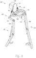
Figure 7 is a perspective drawing of an exoskeleton. -
Figure 8 is a perspective drawing of an exoskeleton. -
Figure 9 is a perspective drawing in accordance with an embodiment of the present invention. -
Figure 10 is a partial view of the invention of the embodiment ofFigure 9 . -
Figure 11 is a partial view of the invention of the embodiment ofFigure 9 . -
Figure 12 is a perspective drawing in accordance with an embodiment of the present invention. -
Figure 13 is a perspective drawing of an exoskeleton. -
Figure 14 is a perspective drawing in accordance with an embodiment of the present invention. -
Figure 15 is a perspective drawing in accordance with an embodiment of the present invention. -
Figure 16 is a perspective drawing in accordance with an embodiment of the exoskeleton foot. -
Figure 17 is a perspective drawing in accordance with an embodiment of the exoskeleton foot. -
Figure 18 is a perspective drawing in accordance with an embodiment of the exoskeleton foot. -
Figure 19 is a perspective drawing in accordance with an embodiment of the exoskeleton foot. -
Figure 20 is a perspective drawing in accordance with an embodiment of the invention. -
Figure 21 is a perspective drawing in accordance with an embodiment of the invention. -
Figure 22 is a drawing in accordance with an embodiment of the exoskeleton foot. -
Figure 23 is a drawing in accordance with an embodiment of the exoskeleton foot. -
Figure 24 is a drawing in accordance with an embodiment of the exoskeleton foot. -
Figure 25 is a drawing in accordance with an embodiment of the exoskeleton foot. -
Figure 26 is a drawing in accordance with an embodiment of the exoskeleton foot. -
Figure 27 is a drawing representing an embodiment of the exoskeleton hydraulic circuitry. -
Figure 28 is a drawing representing an embodiment of the exoskeleton hydraulic circuitry. -
Figure 29 is a drawing representing an embodiment of the exoskeleton hydraulic circuitry. -
Figure 30 is a drawing representing an embodiment of the exoskeleton hydraulic circuitry. -
Figure 31 is a drawing representing an embodiment of the exoskeleton hydraulic circuitry. -
Figure 32 is a drawing representing an embodiment of the exoskeleton hydraulic circuitry. -
Figure 33 is a drawing representing an embodiment of the exoskeleton hydraulic circuitry. -
Figure 34 is a perspective drawing of an exoskeleton. -
Figure 35 is a drawing representing an embodiment of the exoskeleton. -
Figure 36 is a drawing representing an embodiment of the exoskeleton. - The following description sets forth numerous specific configurations, parameters, and the like. It should be recognized, however, that such description is not intended as a limitation on the scope of the present invention, but is instead provided as a description of exemplary embodiments.
-
Figures 1 and2 are front view and rear view perspective drawings illustrating alower extremity exoskeleton 100.Lower extremity exoskeleton 100 is configurable to be coupled to aperson 187.Lower extremity exoskeleton 100 comprises two leg supports 101 and 102 which are configurable to be coupled to the person's lower limbs and configured to rest on the ground during the stance phase of each leg support. The leg supports comprisethigh links shank links knee joints arrows Lower extremity exoskeleton 100 further comprises anexoskeleton trunk 109.Exoskeleton trunk 109, among other components, comprises ahuman interface device 150.Exoskeleton trunk 109 is configurable to be coupled to the person's upper body throughhuman interface device 150. The person's upper body means any location above the thighs.Exoskeleton trunk 109 is rotatably connectable tothigh links extension joints arrows extension axes - In operation the energy required for flexion and extension movement between a shank link (105 or 106) and the corresponding thigh link (103 and 104) of a leg support over a cyclic knee motion is provided by
person 187. A cyclic knee motion here is defined as a motion where the initial and the final configurations of a shank link (105 or 106) and its corresponding thigh link (103 or 104) with respect to each other are nearly identical. In particular when a leg support is in a swing phase, a cyclic knee motion is a motion where the leg support is not in contact with the ground and the initial and the final configurations of the corresponding shank link and thigh link with respect to each other are nearly identical. Likewise, when a leg support is in a stance phase, a cyclic knee motion is a motion where the leg support is in contact with the ground and the initial and the final configurations of the corresponding shank link and thigh link with respect to each other are nearly identical. - In the above example, the torque required for flexion or extension between shank link (105 or 106) and the corresponding thigh link (103 and 104) is provided by
person 187. Twoknee joints lower extremity exoskeleton 100 to provide power for sensors, computers and other components, but does not provide energy for flexion and extension motion between the shank links the thigh links. By power source we mean any system that produces power such as batteries, compressed gas, air compressors, hydraulic compressors, combustion engines, solar cells, and the like. - In some examples, each said leg support is configured to allow flexion of the respective knee joint during the swing phase, and to resist flexion of the respective knee joint during the stance phase to allow the transfer of a force to the ground.
- In operation,
person 187 couples to (or wears)lower extremity exoskeleton 100 by coupling to human interface device 150 (a simple belt in this case ofFigure 1 ) and by coupling to two leg supports 101 and 102. In some embodiments as shown inFigure 1 , leg supports 101 and 102 compriseshank holding devices couple person 187 to leg supports 101 and 102. - In some examples, the energy required for flexion and extension of
thigh links extension axes person 187. A cyclic hip motion here is defined as a motion where the initial and the final configurations of a thigh link (103 or 104) with respect toexoskeleton trunk 109 are nearly identical. - In some examples as shown in
Figure 1 ,exoskeleton trunk 109 includes twohip links thigh links extension joints extension axes hip links arrows - In some examples,
exoskeleton trunk 109 is configured to hold arear load 118 behindperson 187. In some examples, as shown inFigure 1 ,rear load 118 is held byhip links exoskeleton trunk 109 further comprises extension frames 119 and 120 configured to hold afront load 154 in front ofperson 187. In some examples (as shown inFigure 1 ) extension frames 119 and 120 are connectable tohip links rear load 118 andfront load 154 include without limitation, backpack, baby carrier, food containers, sacks, water jugs, tool boxes, barrels, ammunition, weaponry, bedding, first aid supplies, golf bags, mail bags, camera, leaf blower, compressor, electromechanical machineries and combinations thereof. In some examples,rear load 118 and/orfront load 154 are another person being carried byperson 187. In some examples,exoskeleton trunk 109 supports a portion of the weight ofperson 187 throughhuman interface device 150. - In some examples, as shown in
Figure 3 ,exoskeleton trunk 109 further comprises a hipresilient element 116 configured to apply a torque betweenhip links resilient element 116 may be chosen such that its force generally holds up the weight of the leg supports 101 or 102 during swing phase. - Some examples, as shown in
Figure 3 , may also include a hip abduction stop 211 which limits the abduction ofhip links Figure 3 ,abduction stop 211 is created using a wire rope.Wire rope 211 limits the abduction of leg supports 101 and 102 but allows adduction of leg supports 101 and 102. - In accordance with another example,
Figure 4 is a perspective drawing whereexoskeleton trunk 109 includes twohip links thigh links support legs exoskeleton trunk 109, whereinhip links Figure 4 , this is accomplished byleaf spring 153. - In accordance with another example,
Figure 5 is a perspective drawing whereinexoskeleton trunk 109 further comprises a connectingbracket 117 configured to transfer the weight ofrear load 118 toexoskeleton trunk 109.Exoskeleton trunk 109 further comprises twohip links thigh links exoskeleton trunk 109.Hip links bracket 117 via two hip abduction-adduction joints adduction axes adduction axes adduction joints Figure 6 , hip abduction-adduction joints adduction joint 113 and hip abduction-adduction axes adduction axis 112. - In some examples, as shown in
Figure 6 ,exoskeleton trunk 109 further comprises hip abduction-adductionresilient elements hip links bracket 117. Examples of hip abduction-adduction resilient elements include, without limitation, extension spring, compression spring, gas spring, air spring, rubber, surgical tube, leaf springs, bungee cord and combinations thereof. The stiffness of hip abduction-adductionresilient elements Figure 7 , connectingbracket 117 further comprises extension frames 119 and 120 configured to holdfront load 154 in front ofperson 187. - In some examples, as shown in
Figures 1 ,5 ,6 and7 ,exoskeleton trunk 109 compriseshuman interface device 150 capable of couplingperson 187 tolower extremity exoskeleton 100. Examples ofhuman interface device 150 comprise an element or combination of elements including, without limitation, vests, belts, straps, shoulder straps, chest straps, body cast, harness, and waist belts. In some embodimenthuman interface device 150 transfers a portion of the weight ofperson 187 toexoskeleton trunk 109.Figure 13 shows an embodiment of the invention wherehuman interface device 150 comprises a specially-designed harness 229 to fit the body ofperson 187. Harness 229 transfers a portion of the weight ofperson 187 toexoskeleton trunk 109. - In some examples, as shown in
Figure 8 ,hip links bracket 117. In the embodiment shown inFigure 8 , this is accomplished by a hipcompliant member 153 which in this case is a leaf spring. - In some examples, as shown in
Figure 8 ,exoskeleton trunk 109 comprises abackpack frame 180 that allows a backpack to be coupled tolower extremity exoskeleton 100. In some embodiments,backpack frame 180 is connected to connectingbracket 117. The human interface devices 150 (such as a belt and shoulder straps) have been omitted in this figure for clarity. - In accordance with an embodiment of the invention,
Figure 9 is a perspective drawing wherein leg supports 101 and 102 further include thigh abduction-adduction joints axes adduction joints extension joints Figure 10 which is a partial view of the same embodiment ofFigure 9 . - In some embodiments of the invention, as shown in
Figure 10 , leg supports 101 and 102 comprise a thigh adduction stop 185 which limits or preventsthigh links leg support 101 are shown byarrows Figure 10 , thigh abduction-adduction joint 123 includes a thigh adduction stop 185 which bears on athigh stop surface 186. Thigh adduction stop 185 limits the adduction of thigh abduction-adduction joint 123. The unrestricted adduction of thigh abduction-adduction joint 123 would causehip link 114 to move downwardly alongarrow 204 during stance thereby dropping (lowering) the load. Such abduction-only joints forjoints - In some embodiments, as shown in
Figures 9 and10 , leg supports 101 and 102 further comprise leg rotation joints 127 and 128 configured to allow rotation of leg supports 101 and 102. In some embodiments, leg rotation joints 127 and 128 are located aboveknee joints Lines Figure 10 represent the rotation axes of leg rotation joints 127 and 128. InFigures 10 and11 , this is accomplished by providing for a sliding contact between thehip rotation shaft 166 and thehip rotation journal 168.Arrows - In some embodiments, as shown in
Figure 11 , leg rotation joint 127 includes a leg rotationresilient element 129. This leg rotation resilient element provides a restoring torque which generally restores the leg back to a neutral position. Leg rotationresilient element 129 can be constructed in many ways, with the particular cross section shown inFigure 11 being advantageous when using an elastomeric material to construct the element. Leg rotationresilient element 129 is shown partially deflected for illustration purposes. - Also, in some embodiments, as shown in
Figure 10 andFigure 11 , leg supports 101 and 102 further comprise compression-elongation mechanisms exoskeleton trunk 109 and the respective knee flexion-extension joints elongation mechanisms extension joints extension joints hip rotation shaft 166 sliding further into the hip rotation journal 168 (shown forleg 101 only). The leg rotationresilient element 129 is allowed to slide into aclearance cavity 170. In some embodiments, compression-elongation mechanism resilient element 133. This leg compression-elongation resilient element acts as a spring and provides a restoring force which generally restores the leg support back to a neutral configuration. In the embodiment ofFigure 11 , this is illustrated by a helical spring. - In some embodiments, as shown in
Figure 12 ,lower extremity exoskeleton 100 further comprises two swing resilient elements configured to apply torque betweenthigh links exoskeleton trunk 109. In operation swingresilient element 221 pushesleg link 101 forward alongarrows 222 during swing phase. This allows the person to swing the thigh links forward with less effort.Gas spring 221 includes agas spring piston 223 and agas spring cylinder 224. In operation the force ofcompressed gas 225 ingas spring cylinder 224 forcesgas spring piston 223 againstcam 226 thereby pushingleg link 101 alongarrow 222. Examples of a swing resilient element, 221, include, without limitation, extension spring, compression spring, leaf spring, gas spring, air spring, rubber, elastomer, surgical tube, bungee cord and combinations thereof. The stiffness of swingresilient element 221 may be chosen to give appropriate level of comfort. - In some embodiments, as shown in
Figure 9 ,exoskeleton trunk cover 171 may cover some components ofexoskeleton trunk 109 including parts ofhip links Figures 3 or6 depending on the preferred choice of hipresilient element 116 or hip abduction-adductionresilient elements - In some embodiments as shown in
Figure 9 ,thigh links thigh holding devices person 187 to couple to leg supports 101 and 102. Eachthigh holding device Figure 1 ,shank links comprise holding devices person 187 to couple to leg supports 101 and 102. Eachshank holding device - In some embodiments exoskeleton 100 comprises two
torque generators knee joints knee joints lower extremity exoskeleton 100 to bear a load and transfer the load forces (e.g., load weight) to the ground. - In some embodiments,
torque generators Figure 1, through Figure 9 torque generators hydraulic torque generator - In some embodiments, as shown in
Figure 13 ,torque generators rotary dampers - In some
embodiments torque generators knee joints embodiments torque generators knee joints torque generators knee joints Figure 13 . - In some embodiments, as shown in
Figure 9 , leg supports 101 and 102 furthercomprise exoskeleton feet shank links shank links exoskeleton feet person 187. In some embodiments, as shown inFigure 9 , the coupling to person's feet is accomplished by using clam-shell type bindings Figure 14 ,exoskeleton feet exoskeleton shoes person 187 thereby allowingexoskeleton feet person 187. In some embodiments, as shown inFigure 15 ,exoskeleton feet exoskeleton insoles exoskeleton feet person 187.Insoles - According to the invention, as shown in
Figure 9 ,exoskeleton feet shank links compliant elements Figure 16 shows a close-up view ofexoskeleton feet 139. In this example, ankle compliant elements 181 (and 182) each are constructed of a metal ball-and-socket joint 231 surrounded by an elastomerdonut shape element 230 which creates compliance in all directions of rotations. - In some embodiments,
exoskeleton feet shank links Figure 17 shows an embodiment of this type of exoskeleton where ankle plantar-dorsi flexion axis 172 is generally parallel to the plantar-dorsi flexion axis in the human ankle. In some embodiments, each leg support further comprises at least one ankle plantar-dorsi flexionresilient element 141 resisting the rotation of respective exoskeleton foot about ankle plantar-dorsi flexion axis 172. - In some embodiments, as shown in
Figure 18 ,exoskeleton feet adduction axes 174 and 175 relative toshank links 105.Figure 18 shows an embodiment of this type of exoskeleton where ankle abduction-adduction axis 174 is generally parallel to the abduction-adduction axis in the human ankle. In some embodiments each leg support further comprises at least one ankle abduction-adductionresilient element 142 resisting the rotation ofexoskeleton foot 139 about ankle abduction-adduction axis 174. - In some embodiments, as shown in
Figure 19 ,exoskeleton feet rotation axes 147 and 148 relative toshank links Figure 19 shows an embodiment of this type of exoskeleton whereankle rotation axis 147 is generally parallel to the rotation axis in the human ankle. In some embodiments, resilient elements can be included in the ankle to resist the rotation of theexoskeleton foot 139 aboutankle rotation axis 147. - In some embodiments, as shown in
Figure 20 ,lower extremity exoskeleton 100 further comprisescontroller 159 configured to controltorque generators Controller 159, in some embodiments, is mounted toexoskeleton trunk 109. In someembodiments controller 159 is mounted totorque generators Controller 159 may be a simple mechanical device consisting of hydraulic or pneumatic circuitry or it may include electronic elements as well. - In some embodiments, as shown in
Figure 21 ,exoskeleton 100 comprises at least onefoot sensor 160 per leg support which produces astance signal 190 representing the force on the bottom of each foot ofperson 187. The information fromfoot sensor 160 identifies whether the foot ofperson 187 is in a stance phase or in a swing phase.Controller 159 controls thetorque generators - In some embodiments, as shown in
Figure 22 ,foot sensors 160 are integrated intoexoskeleton feet Figure 22 ,foot sensor 160 is a pressure sensor measuring the pressure in amedia 191 trapped in afoot sensor cavity 192 insideexoskeleton foot 139.Figure 16 shows an embodiment where a tube is used as afoot sensor cavity 192.Pressure sensor 160 measures the pressure in amedia 191 trapped in afoot sensor cavity 192. In some cases, thestance signal 190 may take the form of themedia 191 itself ported in a small tube from thecavity 192 to thecontroller 159 where the pressure in the media is used to move a mechanical valving in response to person's force onexoskeleton feet controller 159. -
Figure 23 shows another embodiment whereinfoot sensor 160 is a force sensor connectable to exoskeletonfoot 139. In some embodiments, as shown inFigure 24 ,foot sensor 160 is located inside the human shoe like an insole and its output signal represents the force on the bottom of the human foot. This type would be particularly useful in embodiments of the invention such as those shown inFigure 14 or15 . In some embodiments, as shown inFigure 25 ,foot sensor 160 is connected to the bottom of the human shoe and senses the force on the bottom of the human foot. In some embodiments, as shown inFigure 26 ,foot sensor 160 is located inside the human shoe sole and senses the force on the bottom of the human foot. -
Foot sensor 160 comprises any sensor or combination of sensors capable of performing the indicated functions. Examples offoot sensor 160 include, without limitation, force sensors, strain-gage based force sensors, piezoelectric force sensors, force sensing resistors, pressure sensors, switches, tape switches and combinations thereof. In someembodiments foot sensor 160 is a switch that represents the existence of a force greater than some threshold force on the bottom of the foot ofperson 187. -
Controller 159 controls the resistance to flexion inknee joints foot sensor 160 detects the stance phase in the right leg support,controller 159 will increase the impedance oftorque generator 110 so knee joint 107 resists flexion. Conversely, whenfoot sensor 160 detects the swing phase,controller 159 will decrease the impedance oftorque generator 110 so no resistance to flexion occurs inknee joint 107. Large impedances oftorque generators knee joints torque generators knee joints - It is important to note that a foot sensor is not a requirement of the invention since there are other methods to determine when stance phase and swing phase are occurring. One such method is to sense when the knee hyperextends (as typically occurs when the leg support swings directly under the person's body during stance) and to assume that swing phase begins at that moment. The end of swing phase would then be estimated by detecting when the knee stops extending. To implement this strategy,
controller 159 might be a simple mechanical/hydraulic device built into a hydraulic cylinder which uses the motion of the cylinder to actuate the valving within it. -
Figure 27 shows an embodiment of the invention forleg support 101 wheretorque generator 110 comprises hydraulic piston-cylinder 193 andcontroller 159 includes ahydraulic circuitry 194 to control the fluid flow to hydraulic piston-cylinder 193. In general, during stance phase,hydraulic circuitry 194 restricts the fluid flow from hydraulic piston-cylinder 193. The restriction in the fluid flow leads to large impedance for the hydraulic piston-cylinder 193 and allowsleg support 101 to resist flexion. Conversely, a small restriction in the fluid flow leads to small impedance for piston-cylinder 193 and allowsleg support 101 to flex easily. - In some embodiments,
controller 159 controls the fluid flow from hydraulic piston-cylinder 193 as a function ofstance signal 190.Foot sensor 160 detects the force on the bottom of the person's foot when the person's foot is on the ground (stance phase).Controller 159 restricts the fluid flow from hydraulic piston-cylinder 193 based on receivedstance signal 190. The restriction in the fluid flow leads to a large impedance for the piston-cylinder 193 and allowsleg support 101 to resist flexion. Whenfoot sensor 160 detects that the person's foot is not on the ground (i.e., there is no force on the bottom of the person's foot),controller 159 decreases the restriction on the fluid flow to hydraulic piston-cylinder 193. A small restriction on the fluid flow leads to a small impedance for piston-cylinder 193 and allowsleg support 101 to flex easily. -
Figure 28 shows an embodiment of the invention wherehydraulic circuitry 194 comprises an actuated flow-restrictingvalve 200 connecting piston-cylinder 193 to ahydraulic reservoir 195.Controller 159 controls actuated flow-restrictingvalve 200. Actuated flow-restrictingvalve 200 increases the restriction on the fluid flow during stance phase and decreases the restriction on the fluid flow during swing phase. -
Figure 29 shows an embodiment of the invention wherehydraulic circuitry 194 comprises a hydraulic three-way valve 198 connecting piston-cylinder 193 to ahydraulic reservoir 195 either through aneedle valve 196 or abypass line 197. Hydraulic three-way valve 198 connects piston-cylinder 193 tohydraulic reservoir 195 throughneedle valve 196 during stance phase thereby restricting the hydraulic flow and increasing the impedance of piston-cylinder 193. During swing phase, hydraulic three-way valve 198 connects piston-cylinder 193 tohydraulic reservoir 195 throughbypass line 197, thereby increasing the hydraulic fluid flow and decreasing the impedance of piston-cylinder 193. -
Figure 30 represents another embodiment of thehydraulic circuitry 194. This embodiment is similar to the embodiment ofFigure 29 but anadditional check valve 199 has been added to allow the knee to extend easily (no or minimum resistance) at all times. -
Figure 31 represents another embodiment of thehydraulic circuitry 194 where an actuated flow-restrictingvalve 200 capable of controlling its orifice size and acheck valve 199 connect piston-cylinder 193 tohydraulic reservoir 195. Duringstance phase controller 159 restricts the fluid flow by controlling the orifice of actuated flow-restrictingvalve 200. Duringswing phase controller 159 opens actuated flow-restrictingvalve 200 and allows for fluid flow to piston-cylinder 193 thereby decreasing the impedance of piston-cylinder 193. Actuated flow-restrictingvalve 200 comprises any valve or combination of valves capable of performing the indicated functions. Examples of actuatedflow restricting valve 200 include, without limitation, flow control valves, pressure control valves and on-off valves.Check valve 199 allows knee joint 107 to extend easily at all times. -
Figure 32 represents another embodiment of thehydraulic circuitry 194 where a two-way valve 201 capable of selecting between a set orifice size or fully open orifice, andcheck valve 199 connect piston-cylinder 193 tohydraulic reservoir 195. Duringstance phase controller 159 directs the fluid flow to piston-cylinder 193 through the set orifice size of two-way valve 201. Duringswing phase controller 159 directs the fluid flow to piston-cylinder 193 through fully open orifice of two-way valve 201.Check valve 199 allows knee joint 107 to extend easily at all times. -
Figure 33 represents another embodiment of thehydraulic circuitry 194 where a two-way valve 201, acheck valve 199, and aneedle valve 196 connect piston-cylinder 193 tohydraulic reservoir 195. During stance phase,controller 159 blocks the fluid flow in two-way valve 201 and therefore flow reaches piston-cylinder 193 throughneedle valve 196. Duringswing phase controller 159 opens two-way valve 201 and allows for minimum resistance.Check valve 199 allows knee joint 107 to extend easily at all times.Needle valve 196 may be manually or automatically adjusted. - In some
embodiments leg support Figure 34 . In the figure, theshank link 105 includes ashank stop 209 which bears onthigh stop 210 when the knee is hyperextended. The angle of the knee at hyper-extension is illustrated as A in theFigure 34 . Since this angle is less than 180 degrees, the knee joint 107 or 108 will go "over-center" when approaching hyper-extension, meaning that the knee will tend to lock against the stops if the leg supports 101 and 102 is subject to a compressive load, as would be the case forleg support 102 in the situation illustrated in the figure. One skilled in the art will note that there are many such over-center mechanisms which generally tend to force the load vector on the leg support to pass in front of the knee joint. - In some embodiments,
exoskeleton 100 further comprises kneeresilient elements 232 which are configured to encourage flexion ofknee joints knee joints Figure 35 ,resilient elements 232 are in parallel withtorque generators resilient elements 232, as shown inFigure 36 , are in series withtorque generators exoskeleton 100 comprises kneeresilient elements 232 which are configured to encourage extension ofknee joints resilient element 232 to encourage flexion and/or extension of knee joint 107. It is further understood that kneeresilient elements 232 can also be used with the embodiment of the exoskeleton shown inFigure 34 . - While only certain features of the invention have been illustrated and described herein, many modifications and changes will occur to those skilled in the art.
Claims (18)
- A non-therapeutic method of operating a lower extremity exoskeleton (100) to walk, said lower extremity exoskeleton having:two leg supports (101,102) configured to rest on the ground during their stance phases where each said leg support comprises a leg rotation joint (127,128) configured to allow rotation of said leg support, a thigh link (103,104) and a shank link (105,106), wherein each said leg support further comprises an exoskeleton foot (139, 140) configured to be compliantly coupled to respective said person's foot and compliantly coupled to respective said shank link to allow the transfer of forces from said shank link to the ground;two knee joints (107,108), each configured to allow flexion and extension between respective shank link and respective thigh link; andan exoskeleton trunk (109) rotatably connectable to said thigh links of said leg supports allowing for the flexion and extension between said leg supports and said exoskeleton trunk;said method comprising:coupling a person's leg to one of said two leg supports;coupling said person's upper body to said exoskeleton trunk; andallowing the flexion of said respective knee joints during swing phase, and resisting flexion of said respective knee joints during stance phase to allow the transfer of a force to ground;wherein the entire energy required for said flexion and extension between the shank link and the respective thigh link of a leg support over a cyclic knee motion is provided by said person.
- A lower extremity exoskeleton (100), configurable to be coupled to a person (187), said lower extremity exoskeleton comprising:two leg supports (101, 102) configurable to be coupled to said person's lower limbs and configured to rest on the ground during their stance phases where each said leg support comprises a leg rotation joint (127, 128) configured to allow rotation of said leg support, a thigh link (103, 104) and a shank link (105, 106);two knee joints (107, 108), each configured to allow flexion and extension between respective shank link and respective thigh link; andan exoskeleton trunk (109) configurable to be coupled to said person's upper body, rotatably connectable to said thigh links of said leg supports allowing for the flexion and extension between said leg supports and said exoskeleton trunk;characterised in that:each said leg support further comprises an exoskeleton foot configured to be compliantly coupled to respective said person's foot and coupled to respective said shank link to allow the transfer of forces from said shank link to the ground; andthe entire energy required for said flexion and extension between the shank link and the respective thigh link of a leg support over a cyclic knee motion can be provided by said person.
- The device of claim 2, wherein each said leg support is configured to allow flexion of said respective knee joint during a swing phase, and to resist flexion of said respective knee joint during the stance phase to allow the transfer of a force to the ground.
- The device of claim 2, wherein the energy required for flexion and extension movement between a thigh link and said exoskeleton trunk over a cyclic hip motion can be provided by said person.
- The device of claim 2, wherein said exoskeleton trunk further allows for rotation of each said leg support about an abduction-adduction axis generally parallel to ground.
- The device of claim 2, wherein said thigh link of each said leg support further includes a thigh abduction-adduction joint configured to allow abduction of said respective leg support.
- The device of claim 2, wherein each said leg support further comprises a torque generator each configured to allow flexion of said respective knee joint during swing phase, and to resist flexion of said respective knee joint during stance phase to allow the transfer of a force to ground.
- The device of claim 7, wherein said torque generators are hydraulic piston cylinders, wherein the hydraulic piston cylinder's resistive force can be controlled by controlling the fluid flow in a hydraulic valve.
- The device of claim 2, wherein each said exoskeleton foot further comprises a shoe wearable by said person to allow said exoskeleton foot to couple said person's foot.
- The device of claim 2, wherein each said exoskeleton foot further comprises an exoskeleton insole insertable inside said person's shoe to allow said exoskeleton foot to couple said person's foot.
- A lower extremity exoskeleton of claim 2, further comprising:two torque generators capable of producing torque resisting flexion of said respective knee joint; anda controller configured to control said torque generators.
- The lower extremity exoskeleton of claim 11, wherein said controller is configured to increase the resistance of said knee joints to flexion during stance phase.
- The lower extremity exoskeleton of claim 11, wherein said controller is configured to decrease the resistance of said knee joints to flexion during swing phase.
- The lower extremity exoskeleton of claim 11, further comprising at least one foot sensor per said leg support configured to produce a stance signal representing force on the bottom of each human foot; said controller configured to control the resistance to flexion in said exoskeleton knee joints as a function of said stance signals from said foot sensors.
- The device of claim 11, wherein each said torque generator comprises a hydraulic piston-cylinder and said controller includes a hydraulic circuitry connectable to said hydraulic piston-cylinder; said hydraulic circuitry is configured to increase said knee joints' resistance to flexion during a stance phase.
- The device of claim 11, wherein each said torque generator comprises a hydraulic piston-cylinder and said controller includes a hydraulic circuitry connectable to said hydraulic piston-cylinder; said hydraulic circuitry is configured to decrease said knee joints' resistance to flexion during a swing phase.
- The device of claim 11, wherein each said torque generator comprises a hydraulic piston and cylinder and said controller includes a hydraulic circuitry connectable to said hydraulic piston-cylinder; said controller is configured to increase the resistance of said knee joint to flexion when said stance signal represents a force on the bottom of the human foot.
- The device of claim 11, wherein each said torque generator includes hydraulic circuitry comprising an actuated flow restricting valve connecting a hydraulic piston-cylinder to a hydraulic reservoir; said actuated flow restricting valve is configured to restrict the hydraulic fluid flow during a stance phase and allow for minimum resistance fluid flow during a swing phase.
Applications Claiming Priority (2)
| Application Number | Priority Date | Filing Date | Title |
|---|---|---|---|
| US64541705P | 2005-01-18 | 2005-01-18 | |
| PCT/US2006/001981 WO2006078871A2 (en) | 2005-01-18 | 2006-01-18 | Lower extremity exoskeleton |
Publications (3)
| Publication Number | Publication Date |
|---|---|
| EP1845849A2 EP1845849A2 (en) | 2007-10-24 |
| EP1845849A4 EP1845849A4 (en) | 2014-08-13 |
| EP1845849B1 true EP1845849B1 (en) | 2019-04-10 |
Family
ID=36692899
Family Applications (1)
| Application Number | Title | Priority Date | Filing Date |
|---|---|---|---|
| EP06733769.1A Expired - Lifetime EP1845849B1 (en) | 2005-01-18 | 2006-01-18 | Lower extremity exoskeleton |
Country Status (7)
| Country | Link |
|---|---|
| US (1) | US7947004B2 (en) |
| EP (1) | EP1845849B1 (en) |
| CN (1) | CN101132753B (en) |
| AU (1) | AU2006206394B2 (en) |
| CA (1) | CA2601220C (en) |
| IL (1) | IL184396A (en) |
| WO (1) | WO2006078871A2 (en) |
Families Citing this family (200)
| Publication number | Priority date | Publication date | Assignee | Title |
|---|---|---|---|---|
| US7628766B1 (en) | 2003-10-29 | 2009-12-08 | The Regents Of The University Of California | Lower extremity enhancer |
| US7645246B2 (en) * | 2004-08-11 | 2010-01-12 | Omnitek Partners Llc | Method for generating power across a joint of the body during a locomotion cycle |
| CN101175456B (en) * | 2005-04-13 | 2013-03-27 | 加利福尼亚大学董事会 | Semi-motorized lower extremity exoskeleton |
| JP3985001B2 (en) * | 2005-05-17 | 2007-10-03 | 本田技研工業株式会社 | Thigh orthosis for walking assist device |
| NL1029086C2 (en) * | 2005-05-20 | 2006-11-27 | Somas Groep B V | Hip portese, method for preventing hip dislocation and use of a hip portese. |
| WO2007016781A1 (en) | 2005-08-10 | 2007-02-15 | Simon Fraser University | Methods and apparatus for harvesting biomechanical energy |
| CN101400324B (en) * | 2006-03-09 | 2013-09-11 | 加利福尼亚大学董事会 | Power generating leg |
| CA2673399C (en) | 2007-01-05 | 2017-08-29 | Victhom Human Bionics, Inc. | Joint actuation mechanism for a prosthetic and/or orthotic device having a compliant transmission |
| EP2120801B1 (en) | 2007-01-19 | 2018-04-11 | Victhom Laboratory Inc. | Reactive layer control system for prosthetic and orthotic devices |
| EP2163226A1 (en) * | 2007-04-23 | 2010-03-17 | Golden Crab, S.L. | Exoskeleton for safety and control while skiing |
| KR101718345B1 (en) * | 2007-12-26 | 2017-03-21 | 렉스 바이오닉스 리미티드 | Mobility aid |
| EP2257247B1 (en) | 2008-03-24 | 2018-04-25 | Ossur HF | Transfemoral prosthetic systems and methods for operating the same |
| ES2555119T3 (en) * | 2008-05-20 | 2015-12-29 | Ekso Bionics, Inc. | Device and method to reduce a person's energy consumption by using a lower limb exoskeleton |
| DE102008024748A1 (en) * | 2008-05-20 | 2009-12-03 | Otto Bock Healthcare Gmbh | Knee orthosis and method for controlling a knee brace |
| CN102036638B (en) * | 2008-05-20 | 2014-03-26 | 加利福尼亚大学董事会 | Device and method for decreasing oxygen consumption of a person during steady walking by use of a load-carrying exoskeleton |
| US9351855B2 (en) | 2008-06-16 | 2016-05-31 | Ekso Bionics, Inc. | Powered lower extremity orthotic and method of operation |
| EP2346447B1 (en) * | 2008-07-23 | 2019-09-04 | Ekso Bionics, Inc. | An exoskeleton and method for controlling a swing leg of the exoskeleton |
| CN101336848B (en) * | 2008-08-22 | 2011-05-04 | 中国人民解放军海军航空工程学院 | Man machine exoskeleton system and force control method thereof |
| US8114153B2 (en) * | 2008-09-05 | 2012-02-14 | Boston Scientific Scimed, Inc. | Endoprostheses |
| EP2346467B1 (en) | 2008-09-24 | 2019-07-17 | Ekso Bionics, Inc. | Hip and knee actuation systems for lower limb orthotic devices |
| US8096965B2 (en) * | 2008-10-13 | 2012-01-17 | Argo Medical Technologies Ltd. | Locomotion assisting device and method |
| JP4506890B2 (en) * | 2008-10-28 | 2010-07-21 | トヨタ自動車株式会社 | Walking assist device |
| US8968222B2 (en) | 2008-12-18 | 2015-03-03 | Ekso Bionics, Inc. | Wearable material handling system |
| WO2010098880A1 (en) | 2009-02-26 | 2010-09-02 | Ossur Hf. | Orthopedic device for treatment of the back |
| US10124205B2 (en) | 2016-03-14 | 2018-11-13 | Tau Orthopedics, Llc | Toning garment with modular resistance unit docking platforms |
| US9656117B2 (en) * | 2009-06-19 | 2017-05-23 | Tau Orthopedics, Llc | Wearable resistance garment with power measurement |
| US8657769B2 (en) | 2009-11-04 | 2014-02-25 | Ossur Hf | Thoracic lumbar sacral orthosis |
| WO2011075003A1 (en) * | 2009-12-15 | 2011-06-23 | Закрытое Акционерное Общество Научно-Производственный Центр "Огонек" | Method for correcting pathological configurations of segments of the lower extremities and device for realizing same |
| US9333644B2 (en) | 2010-04-09 | 2016-05-10 | Lockheed Martin Corporation | Portable load lifting system |
| AU2011237368B2 (en) * | 2010-04-09 | 2015-07-23 | Ekso Bionics | Exoskeleton load handling system and method of use |
| US9295604B2 (en) | 2010-09-17 | 2016-03-29 | Ekso Bionics, Inc. | Human machine interface for human exoskeleton |
| US9801772B2 (en) | 2010-10-06 | 2017-10-31 | Ekso Bionics, Inc. | Human machine interfaces for lower extremity orthotics |
| CN103200919B (en) * | 2010-11-24 | 2015-04-22 | 川崎重工业株式会社 | Wearable motion assistance device |
| JP5844054B2 (en) * | 2011-02-25 | 2016-01-13 | 川崎重工業株式会社 | Wearable motion support device |
| JP5714874B2 (en) * | 2010-11-24 | 2015-05-07 | 川崎重工業株式会社 | Wearable motion support device |
| WO2012070244A1 (en) * | 2010-11-24 | 2012-05-31 | 川崎重工業株式会社 | Wearable motion assistance device |
| KR20120071555A (en) * | 2010-12-23 | 2012-07-03 | 한국전자통신연구원 | Apparatus for rehabilitation robot |
| US9789603B2 (en) | 2011-04-29 | 2017-10-17 | Sarcos Lc | Teleoperated robotic system |
| US9060884B2 (en) | 2011-05-03 | 2015-06-23 | Victhom Human Bionics Inc. | Impedance simulating motion controller for orthotic and prosthetic applications |
| JP5212957B1 (en) * | 2011-05-16 | 2013-06-19 | 安男 石黒 | Shoes that can also be used as a chair |
| US8736087B2 (en) | 2011-09-01 | 2014-05-27 | Bionic Power Inc. | Methods and apparatus for control of biomechanical energy harvesting |
| US9855654B2 (en) | 2011-09-06 | 2018-01-02 | Wakayama University | Power assist robot apparatus and control method therefor |
| FR2981266B1 (en) | 2011-10-17 | 2013-10-18 | Commissariat Energie Atomique | EXOSQUELETTE LOWER |
| US9532877B2 (en) | 2011-11-11 | 2017-01-03 | Springactive, Inc. | Robotic device and method of using a parallel mechanism |
| US10543109B2 (en) | 2011-11-11 | 2020-01-28 | Össur Iceland Ehf | Prosthetic device and method with compliant linking member and actuating linking member |
| US20130145530A1 (en) * | 2011-12-09 | 2013-06-13 | Manu Mitra | Iron man suit |
| US9095981B2 (en) | 2012-01-11 | 2015-08-04 | Garrett W. Brown | Load and torque resistant caliper exoskeleton |
| US9572705B2 (en) | 2012-01-13 | 2017-02-21 | Ossur Hf | Spinal orthosis |
| TWI474173B (en) * | 2012-02-21 | 2015-02-21 | Hon Hai Prec Ind Co Ltd | Assistance system and assistance method |
| ITTO20120226A1 (en) | 2012-03-15 | 2012-06-14 | Torino Politecnico | ACTIVE TUTOR FOR MOTOR NEURORIABILATION OF LOWER LIMBS, SYSTEM INCLUDING THE SUITOR AND PROCEDURE FOR THE FUNCTIONING OF SUCH SYSTEM. |
| US9044346B2 (en) | 2012-03-29 | 2015-06-02 | össur hf | Powered prosthetic hip joint |
| CN102599998B (en) * | 2012-03-31 | 2015-06-17 | 中国人民解放军总后勤部军需装备研究所 | Mechanical human hip exoskeleton bearing device |
| US9616580B2 (en) | 2012-05-14 | 2017-04-11 | Sarcos Lc | End effector for a robotic arm |
| US9259343B2 (en) | 2012-07-06 | 2016-02-16 | Newman Technologies LLC | Device for mitigating plantar fasciitis |
| WO2014109799A1 (en) | 2012-09-17 | 2014-07-17 | President And Fellows Of Harvard College | Soft exosuit for assistance with human motion |
| WO2014047105A1 (en) | 2012-09-19 | 2014-03-27 | Ossur Hf | Panel attachment and circumference adjustment systems for an orthopedic device |
| AU2013337529B2 (en) * | 2012-11-01 | 2018-03-15 | British Columbia Institute Of Technology | Mobility system including an exoskeleton assembly releasably supported on a wheeled base |
| AU2013359408A1 (en) * | 2012-12-11 | 2014-06-19 | Ekso Bionics, Inc. | Reconfigurable exoskeleton |
| US8683908B1 (en) | 2013-01-17 | 2014-04-01 | Montree Lewis | Personal armor assembly |
| US9554935B2 (en) | 2013-01-24 | 2017-01-31 | Ossur Hf | Orthopedic device for treating complications of the hip |
| CN105377198B (en) | 2013-01-24 | 2017-12-08 | 奥索有限责任公司 | For treating the orthopedic appliance of hip complication |
| US10357391B2 (en) | 2013-01-24 | 2019-07-23 | Ossur Hf | Orthopedic device for treating complications of the hip |
| US9795500B2 (en) | 2013-01-24 | 2017-10-24 | Ossur Hf | Orthopedic device for treating complications of the hip |
| CN105228559B (en) | 2013-02-26 | 2018-01-09 | 奥苏尔公司 | Prosthetic foot with enhanced stability and elastic recovery |
| US9285020B2 (en) | 2013-02-28 | 2016-03-15 | Adicep Technologies, Inc | Open belt clutch |
| EP2967920B1 (en) | 2013-03-14 | 2021-04-21 | Ossur Hf | Prosthetic ankle: a method of controlling based on adaptation to speed |
| CN105142581A (en) * | 2013-03-14 | 2015-12-09 | 埃克苏仿生公司 | Machine to human interfaces for communication from a lower extremity orthotic |
| US9675514B2 (en) | 2013-03-15 | 2017-06-13 | Bionik Laboratories, Inc. | Transmission assembly for use in an exoskeleton apparatus |
| US9808390B2 (en) * | 2013-03-15 | 2017-11-07 | Bionik Laboratories Inc. | Foot plate assembly for use in an exoskeleton apparatus |
| US9855181B2 (en) | 2013-03-15 | 2018-01-02 | Bionik Laboratories, Inc. | Transmission assembly for use in an exoskeleton apparatus |
| CN103110469A (en) * | 2013-03-20 | 2013-05-22 | 上海理工大学 | Electronic knee-joint orthopedic device |
| US9439797B2 (en) | 2013-04-08 | 2016-09-13 | Elwha Llc | Apparatus, system, and method for controlling movement of an orthopedic joint prosthesis in a mammalian subject |
| US10420666B2 (en) | 2013-04-08 | 2019-09-24 | Elwha Llc | Apparatus, system, and method for controlling movement of an orthopedic joint prosthesis in a mammalian subject |
| EP2983624B1 (en) * | 2013-04-08 | 2018-12-19 | Elwha, Llc | Apparatus and system for controlling movement of an orthopedic joint prosthesis in a mammalian subject |
| KR101667179B1 (en) | 2013-05-30 | 2016-10-17 | 호메이윤 카제루니 | User-coupled human-machine interface system and a control method of an exoskeleton thereof |
| EP3777677B1 (en) | 2013-05-31 | 2024-11-06 | President And Fellows Of Harvard College | Soft exosuit for assistance with human motion |
| WO2015006378A1 (en) | 2013-07-09 | 2015-01-15 | Threlfall John | External structural brace apparatus |
| US9226867B2 (en) | 2013-07-09 | 2016-01-05 | John Threlfall | External structural brace apparatus |
| US20150025423A1 (en) | 2013-07-19 | 2015-01-22 | Bionik Laboratories, Inc. | Control system for exoskeleton apparatus |
| WO2015021886A1 (en) | 2013-08-10 | 2015-02-19 | Huang Chen-Ming | Portable human exoskeleton system |
| US10369023B2 (en) * | 2013-11-01 | 2019-08-06 | Rehabilitation Institute Of Chicago | Impedance parameter power control for lower limb assistive device |
| CN103557816B (en) * | 2013-11-07 | 2016-02-03 | 哈尔滨工业大学 | A kind of object wearing device for detecting position deviation |
| ES2810799T3 (en) * | 2013-11-12 | 2021-03-09 | Ekso Bionics Inc | Machine-to-human interfaces for communication from a lower extremity orthosis |
| EP4104757B1 (en) | 2013-12-09 | 2024-10-02 | President and Fellows of Harvard College | Assistive flexible suits, flexible suit systems, and methods for making and control thereof to assist human mobility |
| FR3016821B1 (en) * | 2014-01-29 | 2019-08-02 | Robotiques 3 Dimensions | EXOSQUELETTE WITH FRONT PORT AND METHOD OF USING SUCH AN EXOSQUELET. |
| EP3102171A4 (en) | 2014-02-05 | 2018-03-28 | President and Fellows of Harvard College | Systems, methods, and devices for assisting walking for developmentally-delayed toddlers |
| US20160361222A1 (en) * | 2014-02-25 | 2016-12-15 | Jumpsport, Inc. | Knee and joint rehabilitation exercise device |
| FR3018680B1 (en) * | 2014-03-21 | 2017-09-22 | Wandercraft | EXOSQUELETTE COMPRISING A SUBSTITUTE WITH AN ANKLE |
| EP3616670B1 (en) | 2014-03-31 | 2021-05-05 | Parker Hannifin Corporation | Wearable robotic device |
| WO2015157731A1 (en) | 2014-04-10 | 2015-10-15 | President And Fellows Of Harvard College | Orthopedic device including protruding members |
| WO2015157723A1 (en) | 2014-04-11 | 2015-10-15 | össur hf | Prosthetic foot with removable flexible members |
| US9149938B1 (en) | 2014-04-11 | 2015-10-06 | Harris Corporation | Robotic exoskeleton with adaptive viscous user coupling |
| US10406676B2 (en) | 2014-05-06 | 2019-09-10 | Sarcos Lc | Energy recovering legged robotic device |
| US10512583B2 (en) | 2014-05-06 | 2019-12-24 | Sarcos Lc | Forward or rearward oriented exoskeleton |
| US10766133B2 (en) | 2014-05-06 | 2020-09-08 | Sarcos Lc | Legged robotic device utilizing modifiable linkage mechanism |
| US10533542B2 (en) | 2014-05-06 | 2020-01-14 | Sarcos Lc | Rapidly modulated hydraulic supply for a robotic device |
| US10391634B2 (en) | 2014-05-16 | 2019-08-27 | Massachusetts Institute Of Technology | Apparatus and method for supporting a human body using supernumerary artificial limbs |
| US9604369B2 (en) | 2014-06-04 | 2017-03-28 | Ekso Bionics, Inc. | Exoskeleton and method of increasing the flexibility of an exoskeleton hip joint |
| US9492300B2 (en) | 2014-06-18 | 2016-11-15 | Mawashi Protective Clothing Inc. | Exoskeleton and method of using the same |
| US10561568B1 (en) | 2014-06-19 | 2020-02-18 | Lockheed Martin Corporation | Exoskeleton system providing for a load transfer when a user is standing and kneeling |
| KR101630929B1 (en) * | 2014-08-21 | 2016-06-16 | 주식회사 포스코 | Wearable robot |
| US10238522B2 (en) | 2014-09-05 | 2019-03-26 | Ekso Bionics, Inc. | Exoskeleton device and method of impeding relative movement in the exoskeleton device |
| EP3194769B1 (en) | 2014-09-19 | 2020-04-08 | President and Fellows of Harvard College | Soft exosuit for assistance with human motion |
| US10478368B2 (en) | 2014-09-19 | 2019-11-19 | Samsung Electronics Co., Ltd. | Force transmitting frames and motion assistance apparatuses including the same |
| ES2575255B1 (en) | 2014-11-27 | 2017-04-06 | Consejo Superior De Investigaciones Científicas (Csic) | EXO SKELETON FOR HUMAN MOVEMENT ASSISTANCE |
| US20160158593A1 (en) * | 2014-12-04 | 2016-06-09 | Florida Institute for Human and Machine Cognition | Exoskeleton-Based Exercise and Training Device |
| CA2971671A1 (en) * | 2015-02-09 | 2016-08-18 | Scuola Superiore Di Studi Universitari E Di Perfezionamento Sant'anna | Actuation system for hip orthosis |
| CN104605967B (en) * | 2015-02-26 | 2016-06-15 | 王黎锋 | Two lower limb decompression treatment device |
| US10159592B2 (en) | 2015-02-27 | 2018-12-25 | Ossur Iceland Ehf | Spinal orthosis, kit and method for using the same |
| US10561520B2 (en) | 2015-02-27 | 2020-02-18 | Ossur Iceland Ehf | Spinal orthosis, kit and method for using the same |
| US10398617B2 (en) | 2015-04-29 | 2019-09-03 | Steering Solutions Ip Holding Corporation | Adjustable position pivot for medical assist device |
| US10588811B2 (en) | 2015-04-30 | 2020-03-17 | Steering Solutions Ip Holding Corporation | Low friction gearbox for medical assist device |
| US10390973B2 (en) | 2015-05-11 | 2019-08-27 | The Hong Kong Polytechnic University | Interactive exoskeleton robotic knee system |
| JP6673940B2 (en) | 2015-05-18 | 2020-04-01 | ザ リージェンツ オブ ザ ユニバーシティ オブ カリフォルニア | Arm support exoskeleton |
| US10548800B1 (en) | 2015-06-18 | 2020-02-04 | Lockheed Martin Corporation | Exoskeleton pelvic link having hip joint and inguinal joint |
| KR20180053293A (en) * | 2015-06-23 | 2018-05-21 | 더 리전츠 오브 더 유니버시티 오브 캘리포니아 | Manual power-saving artificial knee |
| US9744093B2 (en) * | 2015-06-26 | 2017-08-29 | U.S. Bionics, Inc. | Leg apparatus |
| US10518404B2 (en) | 2015-07-17 | 2019-12-31 | Lockheed Martin Corporation | Variable force exoskeleton hip joint |
| CA2992738C (en) * | 2015-07-17 | 2018-09-18 | Ekso Bionics, Inc. | Universal tensegrity joints for human exoskeleton |
| US10195736B2 (en) | 2015-07-17 | 2019-02-05 | Lockheed Martin Corporation | Variable force exoskeleton hip joint |
| KR102481533B1 (en) | 2015-09-04 | 2022-12-26 | 삼성전자주식회사 | A motion assist apparatus and a method for controlling thereof |
| CN105105896B (en) * | 2015-09-17 | 2016-11-30 | 武汉大学 | For the adjusting means that wearable lower limb exoskeleton robot is fixing with human body waist |
| US10434360B1 (en) | 2015-10-12 | 2019-10-08 | Eric Hosfeld | Multi-joint exercise machine |
| EP3158893B1 (en) * | 2015-10-21 | 2021-04-28 | noonee AG | Seat unit for wearable sitting posture assisting device |
| CN105167961A (en) * | 2015-10-21 | 2015-12-23 | 陕西福音假肢有限责任公司 | Rehabilitation training robot for paraplegic patients |
| KR102399605B1 (en) | 2015-11-05 | 2022-05-18 | 삼성전자주식회사 | A power transmitting assembly and a motion assist apparatus comprising thereof |
| EP3376895B1 (en) * | 2015-11-18 | 2024-03-27 | The Regents of The University of California | Trunk supporting exoskeleton and method of use |
| US10912346B1 (en) | 2015-11-24 | 2021-02-09 | Lockheed Martin Corporation | Exoskeleton boot and lower link |
| US10124484B1 (en) | 2015-12-08 | 2018-11-13 | Lockheed Martin Corporation | Load-bearing powered exoskeleton using electromyographic control |
| US10058994B2 (en) * | 2015-12-22 | 2018-08-28 | Ekso Bionics, Inc. | Exoskeleton and method of providing an assistive torque to an arm of a wearer |
| US10569413B2 (en) | 2015-12-22 | 2020-02-25 | Ekso Bionics, Inc. | Exoskeleton and method of providing an assistive torque to an arm of a wearer |
| FR3046053B1 (en) * | 2015-12-24 | 2017-12-22 | Sagem Defense Securite | FOOT MODULE FOR AN EXOSQUELET STRUCTURE |
| FR3046233B1 (en) * | 2015-12-28 | 2017-12-29 | Commissariat A L`Energie Atomique Et Aux Energies Alternatives | SENSOR OF THRESHOLD |
| US10195099B2 (en) | 2016-01-11 | 2019-02-05 | Bionic Power Inc. | Method and system for intermittently assisting body motion |
| CN109069278A (en) | 2016-03-13 | 2018-12-21 | 哈佛大学校长及研究员协会 | Flexible member for anchoring to the body |
| US10980698B2 (en) * | 2016-04-15 | 2021-04-20 | Rewalk Robotics Ltd. | Apparatus and systems for controlled collapse of an exoskeleton |
| EP3241531A1 (en) * | 2016-05-04 | 2017-11-08 | noonee AG | Leg unit for a wearable sitting posture assisting device |
| CN105944353A (en) * | 2016-05-15 | 2016-09-21 | 黄圭鹏 | Arm-swinging run-up device |
| CN105856194A (en) * | 2016-05-19 | 2016-08-17 | 成都润惠科技有限公司 | Bearing device for hip exoskeleton |
| US11413210B2 (en) | 2016-06-14 | 2022-08-16 | University Of Houston System | Customizable orthotic/prosthetic braces and lightweight modular exoskeleton |
| CN109789543B (en) | 2016-07-22 | 2022-09-27 | 哈佛大学校长及研究员协会 | Control optimization for wearable systems |
| FR3054434B1 (en) * | 2016-07-28 | 2021-09-10 | Safran Electronics & Defense | EXOSKELETON STRUCTURE FOR USER STRAIN ASSISTANCE |
| WO2018023109A1 (en) | 2016-07-29 | 2018-02-01 | The United States Of America, As Represented By The Secretary, Department Of Health And Human Services | Powered gait assistance systems |
| US10117769B2 (en) | 2016-08-31 | 2018-11-06 | Jay C. Humphrey | Orthopedic knee brace |
| CN106346448B (en) * | 2016-10-11 | 2019-05-03 | 重庆市牛迪科技发展有限公司 | A kind of auxiliary support apparatus |
| KR102058649B1 (en) | 2016-10-24 | 2020-01-22 | 웨어러텍(주) | Modular exoskeleton apparatus |
| US10828767B2 (en) | 2016-11-11 | 2020-11-10 | Sarcos Corp. | Tunable actuator joint modules having energy recovering quasi-passive elastic actuators with internal valve arrangements |
| US10919161B2 (en) | 2016-11-11 | 2021-02-16 | Sarcos Corp. | Clutched joint modules for a robotic system |
| US10765537B2 (en) | 2016-11-11 | 2020-09-08 | Sarcos Corp. | Tunable actuator joint modules having energy recovering quasi-passive elastic actuators for use within a robotic system |
| US10821614B2 (en) | 2016-11-11 | 2020-11-03 | Sarcos Corp. | Clutched joint modules having a quasi-passive elastic actuator for a robotic assembly |
| CN106625598B (en) * | 2016-12-20 | 2018-10-23 | 东南大学 | A kind of knee joint power assisting device that rigidity automatically switches |
| FR3061445B1 (en) * | 2016-12-29 | 2019-05-24 | Safran Electronics & Defense | BONDING DEVICE FOR EXOSKELET STRUCTURE FACILITATING THE LOADING OF LOADS DURING THE MARKET OR THE RACE |
| US11014804B2 (en) | 2017-03-14 | 2021-05-25 | President And Fellows Of Harvard College | Systems and methods for fabricating 3D soft microstructures |
| MX2019012562A (en) | 2017-04-25 | 2019-12-02 | Ossur Iceland Ehf | Interface system in an exoskeleton. |
| CN108066944B (en) * | 2017-08-24 | 2020-01-07 | 深圳市罗伯医疗科技有限公司 | Knee joint walking-aid robot |
| CN108071734B (en) * | 2017-08-24 | 2020-04-07 | 深圳市罗伯医疗科技有限公司 | Damper and walking-aid robot |
| CN108066943A (en) * | 2017-08-24 | 2018-05-25 | 深圳市罗伯医疗科技有限公司 | Knee joint assistant robot and control method |
| WO2019046408A1 (en) | 2017-08-30 | 2019-03-07 | Lockheed Martin Corporation | Automatic sensor selection |
| CN107595544A (en) * | 2017-08-30 | 2018-01-19 | 深圳市罗伯医疗科技有限公司 | A kind of lower limb rehabilitation device control method, system and device |
| WO2019051240A1 (en) | 2017-09-07 | 2019-03-14 | Ossur Iceland Ehf | Thoracic lumbar sacral orthosis attachment |
| CN111148606B (en) | 2017-09-28 | 2023-04-07 | 奥索冰岛有限公司 | Body engaging device |
| US11766350B2 (en) * | 2017-10-10 | 2023-09-26 | The Regents Of The University Of California | Method and apparatus for a passive knee joint |
| CN108030309B (en) * | 2017-11-17 | 2019-08-20 | 华南理工大学 | A kind of height-adjustable ectoskeleton seat |
| US10843330B2 (en) | 2017-12-07 | 2020-11-24 | Sarcos Corp. | Resistance-based joint constraint for a master robotic system |
| US11331809B2 (en) | 2017-12-18 | 2022-05-17 | Sarcos Corp. | Dynamically controlled robotic stiffening element |
| CN108186287A (en) * | 2018-02-01 | 2018-06-22 | 东南大学 | Multiple degrees of freedom energy storage foot mechanism |
| CN108721061B (en) * | 2018-03-26 | 2020-07-31 | 大连交通大学 | A kind of auxiliary mechanical limb device |
| USD876654S1 (en) | 2018-04-24 | 2020-02-25 | Ossur Iceland Ehf | Posterior strut |
| CN110815171B (en) * | 2018-08-09 | 2023-03-21 | 埃克苏仿生公司 | Exoskeleton and method for providing assistance torque to a wearer's arm |
| CN109303669A (en) * | 2018-10-17 | 2019-02-05 | 苏州帝维达生物科技有限公司 | A kind of multiple degrees of freedom movable lower limb healing robot |
| CN109172281B (en) * | 2018-10-17 | 2024-03-19 | 苏州帝维达生物科技有限公司 | A seven-degree-of-freedom lower limb rehabilitation robot |
| FR3087694B1 (en) * | 2018-10-29 | 2020-11-13 | Safran Electronics & Defense | DEVICE INTENDED TO BE POSITIONED CLOSE TO A JOINT AND GENERAL SYSTEM INCLUDING SUCH A DEVICE |
| CN113039046B (en) * | 2018-11-12 | 2024-10-29 | 日本电气株式会社 | Load reduction device, load reduction method, and storage medium storing program |
| US10906191B2 (en) | 2018-12-31 | 2021-02-02 | Sarcos Corp. | Hybrid robotic end effector |
| US11241801B2 (en) | 2018-12-31 | 2022-02-08 | Sarcos Corp. | Robotic end effector with dorsally supported actuation mechanism |
| US11351675B2 (en) | 2018-12-31 | 2022-06-07 | Sarcos Corp. | Robotic end-effector having dynamic stiffening elements for conforming object interaction |
| CN109760026A (en) * | 2019-03-14 | 2019-05-17 | 布法罗机器人科技(成都)有限公司 | Hip mechanism for wearable ectoskeleton |
| CN110900583A (en) * | 2019-12-27 | 2020-03-24 | 中北大学 | Lower limb exoskeleton assisted load bearing mechanism |
| CN111249114B (en) * | 2020-01-16 | 2022-05-17 | 江西省人民医院 | Crotch skeleton postoperative mount that possesses self-supporting |
| CN111282286A (en) * | 2020-02-26 | 2020-06-16 | 苏州新派特信息科技有限公司 | Wearable dinosaur skeleton equipment |
| CN112353540A (en) * | 2020-10-09 | 2021-02-12 | 重庆医科大学附属永川医院 | Body shape correcting device for legs of children |
| CN114504469A (en) * | 2020-11-17 | 2022-05-17 | 首都医科大学宣武医院 | Exoskeleton system and method of manufacturing same |
| US11833676B2 (en) | 2020-12-07 | 2023-12-05 | Sarcos Corp. | Combining sensor output data to prevent unsafe operation of an exoskeleton |
| CN112659104A (en) * | 2020-12-31 | 2021-04-16 | 上海微电机研究所(中国电子科技集团公司第二十一研究所) | Auxiliary load type lower limb exoskeleton power-assisted robot |
| US11794345B2 (en) | 2020-12-31 | 2023-10-24 | Sarcos Corp. | Unified robotic vehicle systems and methods of control |
| CN112975908B (en) * | 2021-02-19 | 2024-09-24 | 华南理工大学 | Hydraulic system and hydraulic driving method for load-carrying mobile exoskeleton |
| US11918475B2 (en) | 2021-03-31 | 2024-03-05 | DePuy Synthes Products, Inc. | Modular acetabular surgical implant assembly |
| FR3127427A1 (en) * | 2021-09-29 | 2023-03-31 | Supersonic Imagine | Wearable medical device |
| CN115179263B (en) * | 2022-07-22 | 2024-08-23 | 哈尔滨工业大学 | A heterogeneous load-bearing exoskeleton robot |
| CN115213870A (en) * | 2022-07-25 | 2022-10-21 | 贵州航天控制技术有限公司 | Power-assisted exoskeleton equipment, control method thereof and power-assisted exoskeleton system |
| CN115091442B (en) * | 2022-08-09 | 2024-09-03 | 朱岩 | Energy-storage exoskeleton capable of bending knee |
| US11826907B1 (en) | 2022-08-17 | 2023-11-28 | Sarcos Corp. | Robotic joint system with length adapter |
| US11717956B1 (en) | 2022-08-29 | 2023-08-08 | Sarcos Corp. | Robotic joint system with integrated safety |
| US20240075612A1 (en) | 2022-09-02 | 2024-03-07 | Motion Augmented LLC | Modular motor units and methods for making the same for active-passive robotic exoskeleton systems |
| CN115531144A (en) * | 2022-10-14 | 2022-12-30 | 哈尔滨理工大学 | A lower limb exoskeleton robot with stand-up assist |
| TWI816584B (en) * | 2022-10-19 | 2023-09-21 | 國立中山大學 | Effort saving auxiliary device |
| US12172298B2 (en) | 2022-11-04 | 2024-12-24 | Sarcos Corp. | Robotic end-effector having dynamic stiffening elements with resilient spacers for conforming object interaction |
| US11924023B1 (en) | 2022-11-17 | 2024-03-05 | Sarcos Corp. | Systems and methods for redundant network communication in a robot |
| US11897132B1 (en) | 2022-11-17 | 2024-02-13 | Sarcos Corp. | Systems and methods for redundant network communication in a robot |
| CN117260678A (en) * | 2023-09-01 | 2023-12-22 | 远也科技(苏州)有限公司 | A kind of joint exoskeleton and knee joint exoskeleton of connecting piece and its application |
Family Cites Families (39)
| Publication number | Priority date | Publication date | Assignee | Title |
|---|---|---|---|---|
| US420178A (en) * | 1890-01-28 | running | ||
| US420179A (en) * | 1890-01-28 | Apparatus for facilitating walking | ||
| US406328A (en) * | 1889-07-02 | Peters | ||
| US440684A (en) * | 1890-11-18 | Apparatus for facilitating walking | ||
| US539872A (en) * | 1895-05-28 | Exercising apparatus | ||
| US807908A (en) * | 1904-06-30 | 1905-12-19 | Auto Physical Trainer Company | Exercising device. |
| US979243A (en) * | 1910-03-29 | 1910-12-20 | William W Anderson | Apparatus for facilitating walking. |
| US1308675A (en) * | 1919-05-06 | 1919-07-01 | Leslie C Kelley | Pedomotor. |
| US3358678A (en) * | 1964-07-29 | 1967-12-19 | Kultsar Emery | Moving and support system for the human body |
| US3449769A (en) * | 1966-06-27 | 1969-06-17 | Cornell Aeronautical Labor Inc | Powered exoskeletal apparatus for amplifying human strength in response to normal body movements |
| US4647004A (en) * | 1977-10-06 | 1987-03-03 | Bihlmaier John A | Pneumatic-hydraulic actuator system |
| GB2206494B (en) * | 1987-06-24 | 1991-04-17 | Steeper Hugh Ltd | Orthoses or prostheses for co-ordinating limb movement |
| US5054476A (en) * | 1989-03-24 | 1991-10-08 | Petrofsky Research, Inc. | Orthosis for assistance in walking |
| GB2231500B (en) * | 1989-05-16 | 1993-04-14 | David Hart | Walking support orthosis |
| US4964628A (en) * | 1989-06-30 | 1990-10-23 | Center For Orthotics Design, Inc. | Hip-reciprocating apparatus |
| US5020790A (en) * | 1990-10-23 | 1991-06-04 | Board Of Supervisors Of Louisiana State University And Agricultural And Mechanical College | Powered gait orthosis |
| US5658242A (en) * | 1991-03-13 | 1997-08-19 | Polycane Australia Pty Ltd. | Walking aid |
| US5282460A (en) * | 1992-01-06 | 1994-02-01 | Joyce Ann Boldt | Three axis mechanical joint for a power assist device |
| US6500210B1 (en) * | 1992-09-08 | 2002-12-31 | Seattle Systems, Inc. | System and method for providing a sense of feel in a prosthetic or sensory impaired limb |
| US5476441A (en) | 1993-09-30 | 1995-12-19 | Massachusetts Institute Of Technology | Controlled-brake orthosis |
| US5662693A (en) * | 1995-06-05 | 1997-09-02 | The United States Of America As Represented By The Secretary Of The Air Force | Mobility assist for the paralyzed, amputeed and spastic person |
| IT1281584B1 (en) * | 1996-01-02 | 1998-02-20 | Benito Ferrati | ORTHOPEDIC EQUIPMENT FOR WALKING AND REHABILITATION OF MOTU-INJURED PEOPLE WITH THE USE OF ELECTRONIC AND REALITY UNITS |
| JPH1142259A (en) * | 1997-07-28 | 1999-02-16 | Technol Res Assoc Of Medical & Welfare Apparatus | Walking aid |
| US6821233B1 (en) * | 1998-11-13 | 2004-11-23 | Hocoma Ag | Device and method for automating treadmill therapy |
| US6422329B1 (en) * | 1999-11-12 | 2002-07-23 | Homayoon Kazerooni | Human assisted walking robot |
| US6589195B1 (en) * | 2000-05-26 | 2003-07-08 | Orthomerica Products, Inc. | Modular adjustable prophylactic hip orthosis and adduction/abduction joint |
| RU2165752C1 (en) * | 2000-06-21 | 2001-04-27 | ЗАО Научно-производственный центр ОГОНЕК | Device for treating the patients suffering from complications due to central nervous system lesions and injured locomotor apparatus |
| US7153242B2 (en) * | 2001-05-24 | 2006-12-26 | Amit Goffer | Gait-locomotor apparatus |
| US6676707B2 (en) * | 2001-05-24 | 2004-01-13 | Tachung C. Yih | Prosthetic devices for upper and lower limbs |
| JP3934107B2 (en) * | 2001-06-08 | 2007-06-20 | エフ ホフマン−ラ ロッシュ アクチェン ゲゼルシャフト | Test strip for collecting body fluid and method for collecting body fluid |
| GB0128528D0 (en) * | 2001-11-29 | 2002-01-23 | Koninkl Philips Electronics Nv | Shoe based force sensor and equipment for use with the same |
| US6966882B2 (en) * | 2002-11-25 | 2005-11-22 | Tibion Corporation | Active muscle assistance device and method |
| US20040116839A1 (en) * | 2002-12-13 | 2004-06-17 | New Mexico Technical Research Foundation | Gait training apparatus |
| US7111704B2 (en) * | 2004-01-30 | 2006-09-26 | Johnson Welded Products, Inc. | Hydrostatic drive apparatus for a road vehicle |
| US7393335B2 (en) * | 2004-05-06 | 2008-07-01 | Carvey Matthew R | Metabolically efficient leg brace |
| CN1275578C (en) * | 2004-08-10 | 2006-09-20 | 浙江大学 | Lower limb walking external skeleton capable of being worn |
| US7645246B2 (en) * | 2004-08-11 | 2010-01-12 | Omnitek Partners Llc | Method for generating power across a joint of the body during a locomotion cycle |
| JP4344314B2 (en) * | 2004-12-28 | 2009-10-14 | 本田技研工業株式会社 | Weight relief assist device and weight relief assist program |
| CN101400324B (en) * | 2006-03-09 | 2013-09-11 | 加利福尼亚大学董事会 | Power generating leg |
-
2006
- 2006-01-18 EP EP06733769.1A patent/EP1845849B1/en not_active Expired - Lifetime
- 2006-01-18 CA CA2601220A patent/CA2601220C/en not_active Expired - Lifetime
- 2006-01-18 AU AU2006206394A patent/AU2006206394B2/en not_active Expired
- 2006-01-18 US US11/335,392 patent/US7947004B2/en active Active
- 2006-01-18 WO PCT/US2006/001981 patent/WO2006078871A2/en not_active Ceased
- 2006-01-18 CN CN2006800065141A patent/CN101132753B/en not_active Expired - Lifetime
-
2007
- 2007-07-03 IL IL184396A patent/IL184396A/en active IP Right Grant
Non-Patent Citations (1)
| Title |
|---|
| None * |
Also Published As
| Publication number | Publication date |
|---|---|
| CA2601220A1 (en) | 2006-07-27 |
| AU2006206394A1 (en) | 2006-07-27 |
| CA2601220C (en) | 2014-03-18 |
| WO2006078871A2 (en) | 2006-07-27 |
| AU2006206394A2 (en) | 2008-07-31 |
| US20060260620A1 (en) | 2006-11-23 |
| US7947004B2 (en) | 2011-05-24 |
| AU2006206394B2 (en) | 2011-10-13 |
| EP1845849A4 (en) | 2014-08-13 |
| WO2006078871A3 (en) | 2007-09-20 |
| CN101132753A (en) | 2008-02-27 |
| CN101132753B (en) | 2011-06-29 |
| IL184396A (en) | 2012-10-31 |
| IL184396A0 (en) | 2007-10-31 |
| EP1845849A2 (en) | 2007-10-24 |
Similar Documents
| Publication | Publication Date | Title |
|---|---|---|
| EP1845849B1 (en) | Lower extremity exoskeleton | |
| CA2724062C (en) | Device and method for decreasing oxygen consumption of a person during steady walking by use of a load-carrying exoskeleton | |
| EP2687339B1 (en) | Device and method for decreasing energy consumption of a person by use of a lower extremity exoskeleton | |
| EP1874239B1 (en) | Semi-powered lower extremity exoskeleton | |
| US8801641B2 (en) | Exoskeleton and method for controlling a swing leg of the exoskeleton |
Legal Events
| Date | Code | Title | Description |
|---|---|---|---|
| PUAI | Public reference made under article 153(3) epc to a published international application that has entered the european phase |
Free format text: ORIGINAL CODE: 0009012 |
|
| 17P | Request for examination filed |
Effective date: 20070813 |
|
| AK | Designated contracting states |
Kind code of ref document: A2 Designated state(s): AT BE BG CH CY CZ DE DK EE ES FI FR GB GR HU IE IS IT LI LT LU LV MC NL PL PT RO SE SI SK TR |
|
| AX | Request for extension of the european patent |
Extension state: AL BA HR MK YU |
|
| R17D | Deferred search report published (corrected) |
Effective date: 20070920 |
|
| RIC1 | Information provided on ipc code assigned before grant |
Ipc: A61F 2/74 20060101ALI20080124BHEP Ipc: A61G 15/00 20060101AFI20080124BHEP |
|
| RIN1 | Information on inventor provided before grant (corrected) |
Inventor name: ANGOLD, RUSSDON Inventor name: HARDING, NATHAN, H. Inventor name: KAZEROONI, HOMAYOON |
|
| DAX | Request for extension of the european patent (deleted) | ||
| A4 | Supplementary search report drawn up and despatched |
Effective date: 20140716 |
|
| RIC1 | Information provided on ipc code assigned before grant |
Ipc: A61F 2/74 20060101ALI20140710BHEP Ipc: A61G 15/00 20060101AFI20140710BHEP |
|
| STAA | Information on the status of an ep patent application or granted ep patent |
Free format text: STATUS: EXAMINATION IS IN PROGRESS |
|
| 17Q | First examination report despatched |
Effective date: 20161111 |
|
| GRAP | Despatch of communication of intention to grant a patent |
Free format text: ORIGINAL CODE: EPIDOSNIGR1 |
|
| STAA | Information on the status of an ep patent application or granted ep patent |
Free format text: STATUS: GRANT OF PATENT IS INTENDED |
|
| INTG | Intention to grant announced |
Effective date: 20181102 |
|
| GRAS | Grant fee paid |
Free format text: ORIGINAL CODE: EPIDOSNIGR3 |
|
| GRAA | (expected) grant |
Free format text: ORIGINAL CODE: 0009210 |
|
| STAA | Information on the status of an ep patent application or granted ep patent |
Free format text: STATUS: THE PATENT HAS BEEN GRANTED |
|
| AK | Designated contracting states |
Kind code of ref document: B1 Designated state(s): AT BE BG CH CY CZ DE DK EE ES FI FR GB GR HU IE IS IT LI LT LU LV MC NL PL PT RO SE SI SK TR |
|
| REG | Reference to a national code |
Ref country code: GB Ref legal event code: FG4D |
|
| REG | Reference to a national code |
Ref country code: AT Ref legal event code: REF Ref document number: 1117696 Country of ref document: AT Kind code of ref document: T Effective date: 20190415 Ref country code: CH Ref legal event code: EP |
|
| REG | Reference to a national code |
Ref country code: IE Ref legal event code: FG4D |
|
| REG | Reference to a national code |
Ref country code: DE Ref legal event code: R096 Ref document number: 602006057752 Country of ref document: DE |
|
| REG | Reference to a national code |
Ref country code: NL Ref legal event code: MP Effective date: 20190410 |
|
| REG | Reference to a national code |
Ref country code: LT Ref legal event code: MG4D |
|
| REG | Reference to a national code |
Ref country code: AT Ref legal event code: MK05 Ref document number: 1117696 Country of ref document: AT Kind code of ref document: T Effective date: 20190410 |
|
| PG25 | Lapsed in a contracting state [announced via postgrant information from national office to epo] |
Ref country code: NL Free format text: LAPSE BECAUSE OF FAILURE TO SUBMIT A TRANSLATION OF THE DESCRIPTION OR TO PAY THE FEE WITHIN THE PRESCRIBED TIME-LIMIT Effective date: 20190410 |
|
| PG25 | Lapsed in a contracting state [announced via postgrant information from national office to epo] |
Ref country code: FI Free format text: LAPSE BECAUSE OF FAILURE TO SUBMIT A TRANSLATION OF THE DESCRIPTION OR TO PAY THE FEE WITHIN THE PRESCRIBED TIME-LIMIT Effective date: 20190410 Ref country code: SE Free format text: LAPSE BECAUSE OF FAILURE TO SUBMIT A TRANSLATION OF THE DESCRIPTION OR TO PAY THE FEE WITHIN THE PRESCRIBED TIME-LIMIT Effective date: 20190410 Ref country code: PT Free format text: LAPSE BECAUSE OF FAILURE TO SUBMIT A TRANSLATION OF THE DESCRIPTION OR TO PAY THE FEE WITHIN THE PRESCRIBED TIME-LIMIT Effective date: 20190910 Ref country code: LT Free format text: LAPSE BECAUSE OF FAILURE TO SUBMIT A TRANSLATION OF THE DESCRIPTION OR TO PAY THE FEE WITHIN THE PRESCRIBED TIME-LIMIT Effective date: 20190410 Ref country code: ES Free format text: LAPSE BECAUSE OF FAILURE TO SUBMIT A TRANSLATION OF THE DESCRIPTION OR TO PAY THE FEE WITHIN THE PRESCRIBED TIME-LIMIT Effective date: 20190410 |
|
| PG25 | Lapsed in a contracting state [announced via postgrant information from national office to epo] |
Ref country code: BG Free format text: LAPSE BECAUSE OF FAILURE TO SUBMIT A TRANSLATION OF THE DESCRIPTION OR TO PAY THE FEE WITHIN THE PRESCRIBED TIME-LIMIT Effective date: 20190710 Ref country code: GR Free format text: LAPSE BECAUSE OF FAILURE TO SUBMIT A TRANSLATION OF THE DESCRIPTION OR TO PAY THE FEE WITHIN THE PRESCRIBED TIME-LIMIT Effective date: 20190711 Ref country code: PL Free format text: LAPSE BECAUSE OF FAILURE TO SUBMIT A TRANSLATION OF THE DESCRIPTION OR TO PAY THE FEE WITHIN THE PRESCRIBED TIME-LIMIT Effective date: 20190410 Ref country code: LV Free format text: LAPSE BECAUSE OF FAILURE TO SUBMIT A TRANSLATION OF THE DESCRIPTION OR TO PAY THE FEE WITHIN THE PRESCRIBED TIME-LIMIT Effective date: 20190410 |
|
| PG25 | Lapsed in a contracting state [announced via postgrant information from national office to epo] |
Ref country code: AT Free format text: LAPSE BECAUSE OF FAILURE TO SUBMIT A TRANSLATION OF THE DESCRIPTION OR TO PAY THE FEE WITHIN THE PRESCRIBED TIME-LIMIT Effective date: 20190410 Ref country code: IS Free format text: LAPSE BECAUSE OF FAILURE TO SUBMIT A TRANSLATION OF THE DESCRIPTION OR TO PAY THE FEE WITHIN THE PRESCRIBED TIME-LIMIT Effective date: 20190810 |
|
| REG | Reference to a national code |
Ref country code: DE Ref legal event code: R097 Ref document number: 602006057752 Country of ref document: DE |
|
| PG25 | Lapsed in a contracting state [announced via postgrant information from national office to epo] |
Ref country code: EE Free format text: LAPSE BECAUSE OF FAILURE TO SUBMIT A TRANSLATION OF THE DESCRIPTION OR TO PAY THE FEE WITHIN THE PRESCRIBED TIME-LIMIT Effective date: 20190410 Ref country code: DK Free format text: LAPSE BECAUSE OF FAILURE TO SUBMIT A TRANSLATION OF THE DESCRIPTION OR TO PAY THE FEE WITHIN THE PRESCRIBED TIME-LIMIT Effective date: 20190410 Ref country code: RO Free format text: LAPSE BECAUSE OF FAILURE TO SUBMIT A TRANSLATION OF THE DESCRIPTION OR TO PAY THE FEE WITHIN THE PRESCRIBED TIME-LIMIT Effective date: 20190410 Ref country code: SK Free format text: LAPSE BECAUSE OF FAILURE TO SUBMIT A TRANSLATION OF THE DESCRIPTION OR TO PAY THE FEE WITHIN THE PRESCRIBED TIME-LIMIT Effective date: 20190410 Ref country code: CZ Free format text: LAPSE BECAUSE OF FAILURE TO SUBMIT A TRANSLATION OF THE DESCRIPTION OR TO PAY THE FEE WITHIN THE PRESCRIBED TIME-LIMIT Effective date: 20190410 |
|
| PLBE | No opposition filed within time limit |
Free format text: ORIGINAL CODE: 0009261 |
|
| STAA | Information on the status of an ep patent application or granted ep patent |
Free format text: STATUS: NO OPPOSITION FILED WITHIN TIME LIMIT |
|
| PG25 | Lapsed in a contracting state [announced via postgrant information from national office to epo] |
Ref country code: IT Free format text: LAPSE BECAUSE OF FAILURE TO SUBMIT A TRANSLATION OF THE DESCRIPTION OR TO PAY THE FEE WITHIN THE PRESCRIBED TIME-LIMIT Effective date: 20190410 |
|
| 26N | No opposition filed |
Effective date: 20200113 |
|
| PG25 | Lapsed in a contracting state [announced via postgrant information from national office to epo] |
Ref country code: TR Free format text: LAPSE BECAUSE OF FAILURE TO SUBMIT A TRANSLATION OF THE DESCRIPTION OR TO PAY THE FEE WITHIN THE PRESCRIBED TIME-LIMIT Effective date: 20190410 |
|
| PG25 | Lapsed in a contracting state [announced via postgrant information from national office to epo] |
Ref country code: SI Free format text: LAPSE BECAUSE OF FAILURE TO SUBMIT A TRANSLATION OF THE DESCRIPTION OR TO PAY THE FEE WITHIN THE PRESCRIBED TIME-LIMIT Effective date: 20190410 |
|
| PG25 | Lapsed in a contracting state [announced via postgrant information from national office to epo] |
Ref country code: MC Free format text: LAPSE BECAUSE OF FAILURE TO SUBMIT A TRANSLATION OF THE DESCRIPTION OR TO PAY THE FEE WITHIN THE PRESCRIBED TIME-LIMIT Effective date: 20190410 |
|
| REG | Reference to a national code |
Ref country code: CH Ref legal event code: PL |
|
| REG | Reference to a national code |
Ref country code: BE Ref legal event code: MM Effective date: 20200131 |
|
| PG25 | Lapsed in a contracting state [announced via postgrant information from national office to epo] |
Ref country code: LU Free format text: LAPSE BECAUSE OF NON-PAYMENT OF DUE FEES Effective date: 20200118 |
|
| PG25 | Lapsed in a contracting state [announced via postgrant information from national office to epo] |
Ref country code: LI Free format text: LAPSE BECAUSE OF NON-PAYMENT OF DUE FEES Effective date: 20200131 Ref country code: CH Free format text: LAPSE BECAUSE OF NON-PAYMENT OF DUE FEES Effective date: 20200131 Ref country code: BE Free format text: LAPSE BECAUSE OF NON-PAYMENT OF DUE FEES Effective date: 20200131 |
|
| PG25 | Lapsed in a contracting state [announced via postgrant information from national office to epo] |
Ref country code: IE Free format text: LAPSE BECAUSE OF NON-PAYMENT OF DUE FEES Effective date: 20200118 |
|
| PG25 | Lapsed in a contracting state [announced via postgrant information from national office to epo] |
Ref country code: CY Free format text: LAPSE BECAUSE OF FAILURE TO SUBMIT A TRANSLATION OF THE DESCRIPTION OR TO PAY THE FEE WITHIN THE PRESCRIBED TIME-LIMIT Effective date: 20190410 |
|
| PGFP | Annual fee paid to national office [announced via postgrant information from national office to epo] |
Ref country code: DE Payment date: 20250129 Year of fee payment: 20 |
|
| PGFP | Annual fee paid to national office [announced via postgrant information from national office to epo] |
Ref country code: FR Payment date: 20250127 Year of fee payment: 20 |
|
| PGFP | Annual fee paid to national office [announced via postgrant information from national office to epo] |
Ref country code: GB Payment date: 20250127 Year of fee payment: 20 |
|
| REG | Reference to a national code |
Ref country code: DE Ref legal event code: R071 Ref document number: 602006057752 Country of ref document: DE |