EP1844992B1 - Passenger-leg-protection device - Google Patents
Passenger-leg-protection device Download PDFInfo
- Publication number
- EP1844992B1 EP1844992B1 EP07014860A EP07014860A EP1844992B1 EP 1844992 B1 EP1844992 B1 EP 1844992B1 EP 07014860 A EP07014860 A EP 07014860A EP 07014860 A EP07014860 A EP 07014860A EP 1844992 B1 EP1844992 B1 EP 1844992B1
- Authority
- EP
- European Patent Office
- Prior art keywords
- airbag
- folded
- passenger
- roll
- leg
- Prior art date
- Legal status (The legal status is an assumption and is not a legal conclusion. Google has not performed a legal analysis and makes no representation as to the accuracy of the status listed.)
- Expired - Lifetime
Links
- 238000005096 rolling process Methods 0.000 claims description 7
- 238000010586 diagram Methods 0.000 description 45
- 238000000034 method Methods 0.000 description 35
- 210000002414 leg Anatomy 0.000 description 16
- 210000003127 knee Anatomy 0.000 description 4
- 230000001419 dependent effect Effects 0.000 description 1
Images


Classifications
-
- B—PERFORMING OPERATIONS; TRANSPORTING
- B60—VEHICLES IN GENERAL
- B60R—VEHICLES, VEHICLE FITTINGS, OR VEHICLE PARTS, NOT OTHERWISE PROVIDED FOR
- B60R21/00—Arrangements or fittings on vehicles for protecting or preventing injuries to occupants or pedestrians in case of accidents or other traffic risks
- B60R21/02—Occupant safety arrangements or fittings, e.g. crash pads
- B60R21/16—Inflatable occupant restraints or confinements designed to inflate upon impact or impending impact, e.g. air bags
- B60R21/23—Inflatable members
- B60R21/237—Inflatable members characterised by the way they are folded
-
- B—PERFORMING OPERATIONS; TRANSPORTING
- B60—VEHICLES IN GENERAL
- B60R—VEHICLES, VEHICLE FITTINGS, OR VEHICLE PARTS, NOT OTHERWISE PROVIDED FOR
- B60R21/00—Arrangements or fittings on vehicles for protecting or preventing injuries to occupants or pedestrians in case of accidents or other traffic risks
- B60R21/02—Occupant safety arrangements or fittings, e.g. crash pads
- B60R21/16—Inflatable occupant restraints or confinements designed to inflate upon impact or impending impact, e.g. air bags
- B60R21/23—Inflatable members
- B60R21/231—Inflatable members characterised by their shape, construction or spatial configuration
- B60R2021/23169—Inflatable members characterised by their shape, construction or spatial configuration specially adapted for knee protection
-
- B—PERFORMING OPERATIONS; TRANSPORTING
- B60—VEHICLES IN GENERAL
- B60R—VEHICLES, VEHICLE FITTINGS, OR VEHICLE PARTS, NOT OTHERWISE PROVIDED FOR
- B60R21/00—Arrangements or fittings on vehicles for protecting or preventing injuries to occupants or pedestrians in case of accidents or other traffic risks
- B60R21/02—Occupant safety arrangements or fittings, e.g. crash pads
- B60R21/16—Inflatable occupant restraints or confinements designed to inflate upon impact or impending impact, e.g. air bags
- B60R21/20—Arrangements for storing inflatable members in their non-use or deflated condition; Arrangement or mounting of air bag modules or components
- B60R21/217—Inflation fluid source retainers, e.g. reaction canisters; Connection of bags, covers, diffusers or inflation fluid sources therewith or together
- B60R21/2171—Inflation fluid source retainers, e.g. reaction canisters; Connection of bags, covers, diffusers or inflation fluid sources therewith or together specially adapted for elongated cylindrical or bottle-like inflators with a symmetry axis perpendicular to the main direction of bag deployment, e.g. extruded reaction canisters
Definitions
- the present invention relates to a passenger-leg-protection device provided to an instrument panel of a vehicle, and particularly to a device wherein an airbag, which is referred to as "knee bag” or “air knee bag”, is inflated in front of the legs at the time of collision of the vehicle for protecting the legs of the passenger in a high-speed transporting object such as a vehicle or the like.
- an airbag which is referred to as "knee bag” or “air knee bag
- a passenger-leg-protection device has been well known wherein an airbag device is included in an interior member in front of a seat in an automobile, around the height of the lower part of the legs of the passenger, and is inflated at the time of collision of the automobile for receiving the legs of the passenger, particularly, the lower portions from the knees.
- the passenger-leg-protection device comprises a folded airbag, a casing storing the airbag, a gas generator for inflating the airbag, a lid member for covering the front face of the casing, and the like.
- the airbag folded portion disclosed in Japanese Unexamined Patent Application Publication No. 2002-249016 is formed by roll-folding and accordion-folding, and there is the need to employ a high-performance inflator for quick completion of inflation of the airbag folded portion.
- a passenger-leg-protection device comprises: an airbag for inflating in front of the leg portions of the passenger in order to protect the leg portions; a casing for storing the folded airbag; and gas generating means for inflating the airbag, wherein the airbag is formed of panels of a front panel for facing the passenger at the time of completion of inflation, and a rear panel disposed on the opposite side from the front panel, and the airbag is folded into a folded portion having a configuration wherein at least a part of the perimeter of the airbag at the time of completion of inflation is folded inward between the front panel and the rear panel.
- the folded portion of the airbag may have a configuration wherein the upper side of the airbag at the time of completion of inflation is folded inward between the front panel and the rear panel.
- the folded portion of the airbag has a configuration wherein the side portions of the airbag at the time of completion of inflation are folded inward between the front panel and the rear panel.
- the folded portion of the airbag may have a configuration wherein the upper side and the side portions of the airbag at the time of completion of inflation are folded inward between the front panel and the rear panel.
- the folded portion of the airbag has a configuration wherein the lower side of the airbag at the time of completion of inflation is folded inward between the front panel and the rear panel.
- the front panel and the rear panel may form a single pleated portion on the perimeter of the folded portion of the airbag, folded inward between the front panel and the rear panel.
- the front panel and the rear panel may also form two or more pleated portions on the perimeter of the folded portion of the airbag, folded inward between the front panel and the rear panel.
- the airbag is roll-folded as to a rolling axis extending in the horizontal direction of the passenger, into a roll-folded portion, following which both the left and right sides of the roll-folded portion are folded back, whereby the folded portion of the airbag is formed.
- the lower portion of the airbag is expanded below the casing prior to folding, following which the upper portion above the lower portion is roll-folded as to a rolling axis extending in the horizontal direction, and the lower portion is folded back so as to be overlaid on the roll-folded portion on the passenger side, following which both the left and right sides of the roll-folded portion are folded back so as to be overlaid on the lower portion on the passenger side, whereby the folded portion is formed.
- the folded portion of the airbag may have a configuration wherein both the left and right sides of the roll-folded portion are accordion-folded so as to be stored within the casing.
- the folded portion of the airbag may also have a configuration wherein both the left and right sides of the roll-folded portion are roll-folded so as to be stored within the casing.
- an airbag is inflated by gas generating means operating so as to receive the leg portions of the passenger.
- the folded portion of the airbag has a configuration wherein at least a part of the perimeter thereof is folded inward so as to be taken into the airbag between the front panel and rear panel, and accordingly, immediately prior to completion of inflation, the part which has been taken into the airbag extends outward so as to protrude as if the aforementioned part is being discharged from the inner side of the airbag.
- the aforementioned part which has been taken into the airbag is forced outward due to the pressure of the gas within the airbag, thereby enabling the perimeter of the airbag, which has been taken into the airbag, to expand smoothly and quickly without necessitating an increase of the pressure of the gas within the airbag.
- the upper side of the airbag at the time of completion of inflation is folded inward between the front panel and the rear panel.
- the upper side of the airbag extends smoothly and quickly, immediately prior to completion of inflation.
- the side portions of the airbag at the time of completion of inflation are folded inward between the front panel and the rear panel.
- the side portions of the airbag extend smoothly and quickly, immediately prior to completion of inflation.
- the upper side and the side portions of the airbag at the time of completion of inflation are folded inward between the front panel and the rear panel.
- the upper side and the side portions of the airbag extend smoothly and quickly, immediately prior to completion of inflation.
- an arrangement may be made wherein the lower side of the airbag at the time of completion of inflation is folded inward between the front panel and the rear panel, as well as the aforementioned upper side and side portions of the airbag at the time of completion of inflation.
- the lower side of the airbag extends smoothly and quickly, immediately prior to completion of inflation in the same way.
- an arrangement may be made wherein the front panel and the rear panel form a single pleated portion on the perimeter of the folded portion of the airbag, folded inward between the front panel and the rear panel, and furthermore, an arrangement may be made wherein the two or more pleated portions are formed in the same way.
- Such an arrangement wherein the two or more pleated portions have been formed enables smoother and quicker expansion of the aforementioned portion immediately prior to completion of inflation.
- an arrangement wherein the single pleated portion has been formed improves workability for folding the airbag as compared with an arrangement wherein the two or more pleated portions are formed.
- an arrangement may be made wherein the folded portion of the airbag has a configuration wherein the airbag is roll-folded as to a rolling axis extending in the horizontal direction of the passenger, following which both the left and right sides of the roll-folded portion is folded back.
- the roll-folded is formed, thereby reducing the diameter of the roll-folded portion following rolling.
- an arrangement is made wherein the lower portion of the airbag is expanded below the casing prior to folding, following which the upper portion above the aforementioned lower portion is roll-folded as to a rolling axis extending in the horizontal direction, into a roll-folded portion, and the aforementioned lower portion is folded back so as to be overlaid on the aforementioned roll-folded portion on the passenger side, following which both the left and the right sides of the aforementioned roll-folded portion are folded back so as to be overlaid on the aforementioned lower portion on the passenger side, whereby the aforementioned folded portion is formed.
- both the left and right sides of the roll-folded portion which have been folded on the aforementioned lower portion on the passenger side are pushed out from the casing at the same time of inflation of the lower portion of the airbag. Accordingly, both the left and the right sides of the roll-folded portion, thus folded, come loose in the early stage of inflation, thereby enabling smooth and quick expansion of the aforementioned roll-folded portion.
- an arrangement may be made wherein both the left and the right sides of the roll-folded portion are accordion-folded so as to be stored within the casing, or an arrangement may be made wherein both the left and the right sides of the roll-folded portion are roll-folded so as to be stored within the casing.
- An arrangement employing accordion-folding enables quick expansion of the airbag in the horizontal direction.
- the folded portion do not readily come loose at the time of being stored within the casing, thereby improving workability.
- Fig. 1 through Fig. 6 are explanatory diagrams which shows an airbag-folding procedure for passenger-leg-protection devices, wherein Fig. (b) in each is a cross-sectional diagram taken along line B-B in the corresponding Fig. (a).
- Fig. 5(c) is a cross-sectional diagram taken along line C-C in Fig. 5(a) .
- Fig. 7(a), Fig. 7(b), Fig. 7(c) , and Fig. 8 are explanatory diagrams for describing inflating state of the airbag.
- Fig. 8(b) and Fig. 8(c) are cross-sectional diagrams taken along line B-B, and a cross-sectional diagram taken along line C-C, in Fig. 8(a) , respectively.
- the airbag (knee airbag) 1 includes a front panel 1j which faces the passenger at the time of completion of inflation of the airbag 1, and a rear panel 1h on the rear side of the front panel 1j, and is formed in the shape of a flat bag with the perimeters of the panels 1j and 1h in continuation.
- the passenger-leg-protection device includes the airbag 1, a casing 2 for storing the folded airbag 1, an inflator 3 serving as a gas generator for inflating the airbag 1, a lid 4 ( Fig. 6 ) for covering the front opening of the casing 2.
- the inflator 3 is disposed within the airbag 1. Stud bolts (not shown) protrude from the inflator 3 or a holder (not shown) for holding the inflator 3 so as to pass through the lower portion of the rear panel 1h of the airbag 1 and the rear face of the casing 2, and are fixed with nuts (not shown). By fixing the stud bolts with the nuts as described above, the rear end of the airbag 1 is held between the inflator 3 or the holder thereof and the rear face of the casing 2, as well as the inflator 3 being fixed to the casing 2.
- the airbag 1 is extracted from the casing 2, and is expanded flat. In the present device, the airbag 1 is expanded upward from the casing 2. Next, as shown in Fig. 1 , the portion along the upper side (upper end) of the airbag 1 is folded along the horizontal folding line 10 so as to be taken into the airbag 1, whereby a pleated portion 1t is formed of the upper end of the airbag 1 between the front panel 1j and the rear panel 1h.
- both the left and right sides (side ends) of the airbag 1 are folded inward along the vertical pleat line 11 so as to be taken into the airbag 1, whereby pleated portions 1s and 1s are formed of the left end and the right end of the airbag 1 between the front panel 1j and the rear panel 1h, as shown in Fig. 2 .
- the airbag 1 is folded back along a horizontal folding line 12 with a predetermined width (e.g., 20 through 150 mm) away from the aforementioned horizontal folding line 10 from the side of the front panel 1j to the side of the rear panel 1h.
- a predetermined width e.g. 20 through 150 mm
- the airbag 1 is further folded back along a horizontal folding line 13 generally with generally the same width as the aforementioned predetermined width downward from the aforementioned horizontal folding line 12 from the side of the front panel 1j to the side of the rear panel 1h. Furthermore, as shown in Fig. 5 , the airbag 1 is further folded back along a horizontal folding line 14 with generally the same width as the aforementioned predetermined width downward from the aforementioned horizontal folding line 13 from the side of the front panel 1j to the side of the rear panel 1h.
- a roll-shaped airbag intermediate folded portion (which will be referred to as "roll-folded portion” hereafter) 1R is formed as shown in Fig. 5(b).
- Fig. 5(b) is a cross-sectional diagram which shows the roll-folded portion 1R with the airbag 1 rolled clockwise as to the rolling center (folding line 10) in a cross-sectional view of the vehicle taken along the front-back direction, with the passenger at the left side thereof.
- the roll-folded portion 1R has extending portions 1a extending from both the left and right sides of the casing 2 as shown in Fig. 5(a) and 5(c) . Accordingly, the extending portions 1a are folded back at the base ends (the bases portion where the airbag protrudes from the casing 2) along the vertical folding lines 15 (see Fig. 6(a) ) to the passenger side (upper side in Fig. 5(c) and Fig.
- the passenger-leg-protection device is provided within an interior panel in front of a seat, for example, such that the lid 4 and the interior panel form a flat face.
- the lid 4 is opened due to being pushed by the airbag 1, and the accordion-pleated portion 1F of the airbag 1 protrudes in front of the casing 2 as shown in Fig. 7(a) .
- the accordion-folded portion 1F comes loose, and the accordion-folded portion 1F extends in the horizontal direction as to the legs of the passenger, following which the roll-folded portion 1R of the airbag 1 extends upward.
- the aforementioned roll-folded portion 1R wherein the airbag 1 has been rolled clockwise in a cross-sectional view of the passenger being on the left side thereof in the vehicle extends upward in front of the legs of the passenger while rotating in the counterclockwise direction ⁇ in the cross-sectional view, as shown in Fig. 7(c) .
- the roll-folded portion 1R comes loose so as to rotate in front of the legs, and accordingly, the roll-folded portion 1R smoothly extends without the roll-folded portion 1R snagging in front of the legs.
- the passenger-leg-protection device With the passenger-leg-protection device, at the time of expansion of the upper end and both the left and right side ends of the airbag, folded so as to be taken into the airbag as pleated portions 1t, 1s, and 1s, respectively, the upper end and both the left and right side ends of the airbag are forced outward due to the gas pressure within the airbag, thereby enabling smooth and quick expansion of the upper end and both the left and right side ends of the airbag 1 without necessitating increasing the performance of the inflator 3.
- the airbag 1 is folded back along the horizontal folding lines 12, 13, and 14, to the side of the rear panel 1h (roll-folded), into the roll-folded portion 1R, following which the extending portions 1a of the roll-folded portion 1R extending from both the left and right sides of the casing 2 are folded so as to be overlaid on the roll-folded portion 1R on the passenger side.
- the airbag 1 is roll-folded into the roll-folded portion 1R, thereby reducing the diameter of the roll-folded portion 1R following rolling.
- the extending portions 1a are folded in the shape of an accordion, into the accordion-folded portion 1F, so as to be stored within the casing 2, thereby enabling quick expansion of the extending portions 1a at the time of inflation of the airbag.
- each of the pleated portions 1t, 1s, and 1s are formed of the upper end and both the left and the right ends of the airbag between the front panel 1j and the rear panel 1h of the airbag 1, according to the present invention, an arrangement may be made wherein two each of the pleated portions 1t, 1s, and 1s, are formed as shown in Fig. 9 , and furthermore, an arrangement may be made wherein three or more each of the pleated portions 1t, 1s, and 1s, are formed.
- Fig. 9(a) is a plan view in a case of forming two each of pleated portions 1t, 1s, and 1s, at the point-in-time as in Fig. 2(a)
- Fig. 9(b) and Fig. 9(c) are cross-sectional diagrams taken along line B-B, and line C-C, in Fig. 9(a) , respectively.
- an arrangement may be made wherein the pleated portions are formed on the portion of the airbag, other than the upper end or the side ends of the airbag, e.g., across the corner of the airbag 1 by a portion across a corner of the airbag 1 being folded so as to be taken into the airbag. Furthermore, an arrangement may be made wherein the pleated portions are formed on only a single portion of the perimeter of the airbag, and furthermore, an arrangement may be made wherein the pleated portions are formed on multiple portions thereof.
- Fig. 10 shows an arrangement wherein the extending portions 1a (see Fig. 5 ) are folded back on the passenger side (the upper side in Fig. 10 ) along the vertical folding line 16 at the base end thereof, following which the remaining portions are roll-folded into compact roll-folded portions 1r so as to be stored within the casing 2.
- the compact roll-folded portions 1r do not readily come loose, thereby improving workability.
- Fig. 10(a) is a cross-sectional diagram which shows an arrangement wherein the extending portions 1a of the airbag 1 extending from the casing 2 are roll-folded so as to be stored within the casing 2 in the same way as in Fig. 6(a)
- Fig. 10(b) is a cross-sectional diagrams taken along line B-B in Fig. 10(a) .
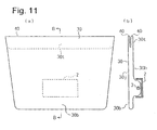
- Fig. 11 through Fig. 15 are explanatory diagrams for describing an airbag-folding procedure for a passenger-leg-protection device according to an embodiment, wherein Fig. (b) in each is a cross-sectional diagram taken along line B-B in the corresponding Fig. (a). Fig. 13(c) is a cross-sectional diagram taken along line C-C in Fig. 13(a) .
- the airbag 30 is extracted from the casing 2, and is expanded flat.
- a lower portion 30b of the airbag 30 is expanded downward from the casing 2, as shown in Fig. 11 .
- the airbag 30 is folded along a horizontal folding line 40 such that the upper side thereof is taken into the airbag 30, so as to form a pleated portion 30t, formed of the upper side of the airbag, between the front panel 30j and the rear panel 30h.
- a left side 30s and a right side 30s of the airbag 30 are folded back along vertical folding lines 41 and 41, respectively, to the side of the rear panel 30h, as shown in Fig. 12 .
- the airbag 30 is folded back along a horizontal folding line 42 with a predetermined width away from the aforementioned horizontal folding line 40 to the side of the rear panel 30h, following which the airbag 30 is further folded back along a horizontal folding line 43 generally with the same width as the aforementioned predetermined width downward from the aforementioned horizontal folding line 42 to the side of the rear panel 30h, and furthermore, airbag 30 is further folded back along a horizontal folding line 44 generally with the same width as the aforementioned predetermined width downward from the aforementioned horizontal folding line 43 to the side of the rear panel 30h.
- the roll-folded portion 30R has been rolled clockwise as to the rolling center (folding line 40) in a cross-sectional view along the front-back direction of the vehicle with the passenger at the left side thereof ( Fig. 13(b) , in the same way as with the roll-folded portion 1R of the airbag 1 of the above-described passenger-leg-protection device shown in Fig. 1 through Fig. 8 .
- the lower portion 30b of the airbag 30 is folded back at the base end thereof along a horizontal folding line 45 to the passenger side (the left side in Fig. 14(b) ) so as to be overlaid on the face of the roll-folded portion 30R on the passenger side.
- extending portions 30a and 30a of the roll-folded portion 30R are folded back at the base ends thereof (portions where the extending portions 30a protrude from the casing 2) along vertical folding lines 46 and 46 (see Fig. 15(a) ) to the passenger side (upper side in Fig. 15(a) ) so as to be overlaid on the face of the lower portion 30b on the passenger side, following which the roll-folded portion 30R is stored within the casing 2.
- the lid 4 is mounted on the casing 2, whereby the passenger-leg-protection device is formed.
- the passenger-leg-protection device is provided within an interior panel in front of a seat, for example, such that the lid 4 and the interior panel form a flat face, as well.
- the airbag 30 of the passenger-leg-protection device is inflated by the inflator 3 operating due to collision of the automobile, first, the gas emitted from the inflator 3 flows into the lower portion 30b of the airbag 30, whereby the lower portion 30b is inflated.
- the lower portion 30b expands downward from the casing 2, at the same time of these extending portions 30a and 30a protruding from the casing 2. Subsequently, the roll-folded portion 30R extends upward.
- the aforementioned roll-folded portion 30R has been rolled clockwise in a longitudinal cross-sectional view of the vehicle with the passenger being on the left side thereof, as well, and accordingly, the roll-folded portion 30R smoothly extends upward in front of the legs of the passenger without snagging in front of the leg portions of the passenger while rotating in the counterclockwise direction in the cross-sectional view, i.e., such that the roll-folded portion 30R rotates in front of the leg portions of the passenger.
- the left and right side portions 30s and 30s of the airbag 30 expand in the side direction of the airbag from the sides of the lower portion of the airbag, at the same time of the upward extension of the roll-folded portion 30R.
- the passenger-leg-protection device at the time of the upper end of the airbag expanding outward from the airbag, which has been folded so as to be taken into the airbag 30 as a pleated portion 30t, the upper end of the airbag is forced outward due to the gas pressure within the airbag, thereby enabling smooth and quick expansion of the upper end outward from the airbag without necessitating an increase of the pressure of the gas within the airbag, i.e., without necessitating an increase of the performance of the inflator 3.
- the lower portion 30b of the airbag 30 is expanded below the casing 2 prior to folding of the airbag 30, following which the portion upward from the lower portion 30b is roll-folded along a horizontal rolling-axis, into the roll-folded portion 30R, and furthermore, the lower portion 30b is folded back so as to be overlaid on the roll-folded portion 30R on the passenger side, following which the extending portions 30a and 30a, extending from both the left and right sides of the roll-folded portion 30R, are folded back so as to be overlaid on the lower portion 30b on the passenger side, and the folded airbag 30 is stored within the casing 2.
- the lower portion 30b is inflated, and the extending portions 30a and 30a, which have been folded back so as to be overlaid on the lower portion 30b on the passenger side, are pushed out from the casing 2 due to the inflation of the lower portion 30b.
- both the left and right sides of the roll-folded portions 30R of the roll-folded portion 30R come loose at the early stage of the inflation of the airbag 30, thereby enabling quick extension of the roll-folded portion 30R.
- Fig. 16 through Fig. 27 are explanatory diagrams for describing an airbag-folding procedure for a passenger-leg-protection device according to another embodiment, wherein Fig. (b) in each is a cross-sectional diagram taken along line B-B in the corresponding Fig. (a).
- an airbag 50 is formed in a shape wherein the width in the horizontal direction becomes smaller the closer to the lower side, as shown in Fig. 16 .
- the airbag 50 includes a casing 70 connected to a rear panel 50h around the lower portion of the airbag 50, for storing a folded article of the airbag 50.
- Reference character 71 denotes an inflator for inflating the airbag 50.
- the inflator 71 is included within the airbag 50. Stud bolts (not shown) protrude from the inflator 71 or a holder (not shown) for holding the inflator 71 so as to pass through the rear panel 50h around the lower portion of the airbag 50, and the rear face of the casing 70, and are fixed with nuts (not shown). By fixing the stud bolts with the nuts as described above, the rear panel 50h of the airbag 50, around the lower portion thereof, is held between the inflator 71 or the holder thereof and the rear face of the casing 70, as well as the inflator 71 being fixed to the casing 70.
- the airbag 50 has a configuration wherein the lower portion 50b of the airbag 50 inflates below the casing 70 at the time of inflation thereof.
- a pleated portion 50p (see Fig. 26(b) ) is formed on the lower portion 50b at the time of folding of the airbag 50.
- the airbag 50 is extracted from the casing 70, and is expanded flat.
- a lower portion 50b of the airbag 50 is expanded downward from the casing 70, as shown in Fig. 16 .
- the airbag 50 is folded along a horizontal folding line 51 such that the upper side of the airbag 50 is taken into the airbag 50, so as to form a pleated portion 50t, formed of the upper side of the airbag, between the front panel 50j and the rear panel 50h.
- a left side 50s and a right side 50s of the airbag 50 are folded back along a vertical folding lines 52 and 52, respectively, to the side of the rear panel 50h, as shown in Fig. 18 .
- the airbag 50 is folded back along a horizontal folding line 53 with a predetermined width away from the aforementioned horizontal folding line 51 to the side of the rear panel 50h ( Fig. 19 ), following which the airbag 50 is further folded back along a horizontal folding line 54 with a predetermined width away from the aforementioned horizontal folding line 53 to the side of the rear panel 50h ( Fig. 20 ).
- the airbag 50 is folded back along the horizontal folding lines 53 and 54 to the side of the rear panel 50h, and accordingly, the portion of the airbag 50, extending above the casing 70, is roll-folded as to the aforementioned horizontal folding line 51 toward the casing 70, whereby a roll-folded portion 50R is formed.
- an intermediate protrusion 50m is formed on the front panel 50h on the lower portion 50b by picking up the front panel 50j to the front side (passenger side) with the front panel 50j being distant from the rear panel 50h ( Fig. 24 ), and the portion from the intermediate protrusion 50m to the border between the lower portion 50b and the roll-folded portion 50R is folded back upward along a horizontal folding line 56 positioned around the border so as to be overlaid on the front face of the roll-folded portion 50R ( Fig. 25 ). Subsequently, the remaining portion from the aforementioned intermediate protrusion 50m to the rear panel 50h is folded back downward from the intermediate protrusion 50m.
- the portion with a predetermined width downward from the aforementioned intermediate protrusion 50m is folded back upward along a horizontal folding line 57, and the remaining portion from the horizontal folding line 57 is folded back upward from the horizontal folding line 57 thereof, so as to form a double-folded lower portion, wherein the remaining portion is overlaid on the front face of the portion between the aforementioned intermediate protrusion 50m and the horizontal folding line 57.
- the portion of the lower portion 50b of the airbag 50, between the aforementioned intermediate protrusions 50m and 50n, is folded within the airbag, whereby the pleated portion 50p is formed on the lower portion 50b thereof.
- extending portions 50a and 50a of the roll-folded portion 50R are folded back at the base ends thereof (portions where the extending portions 50a protrude from the casing 70) along vertical folding lines 58 and 58 (see Fig. 27(b) ) to the front side (upper side in Fig. 27(b) ) so as to be overlaid on the front face of the lower portion 50b, following which the roll-folded portion 50R is stored within the casing 70.
- a lid (not shown) is mounted on the casing 70, whereby the passenger-leg-protection device is formed.
- the passenger-leg-protection device is provided within an interior panel in front of a seat, for example, such that the aforementioned lid and the interior panel form a flat face, as well.
- the airbag 50 of the passenger-leg-protection device in the event that the airbag 50 of the passenger-leg-protection device is inflated by the inflator 71 operating due to collision of the automobile, first, the gas emitted from the inflator 71 flows into the lower portion 50b of the airbag 50, whereby the lower portion 50b is inflated.
- the extending portions 50a and 50a extending from both the left and right sides of the roll-folded portion 50R, which have been folded back so as to be overlaid on the front face of the aforementioned lower portion 50b, are pressed to the passenger side due to inflation of the lower portion 50b so as to press the aforementioned lid, whereby the lid is opened, and the extending portions 50a and 50a expand to the left and right sides of the casing 70.
- the lower portion 50b expands downward from the casing 70, at the same time of these extending portions 50a and 50a protruding from the casing 70.
- the pleated portion 50p of the lower portion 50b, folded within the airbag 50 extends so as to protrude and be discharged from the inner side of the airbag 50.
- the aforementioned roll-folded portion 50R according to the present embodiment also smoothly extends upward in front of the legs of the passenger without snagging while rotating in the counterclockwise direction, the roll-folded portion 50R rotating in front of the leg portions of the passenger.
- the left and right side portions 50s and 50s of the airbag 50 expand in the side direction of the airbag from the sides of the lower portion of the airbag, at the same time of the upward extension of the roll-folded portion 50R.
- the pleated portions 50t formed of the upper end of the airbag which has been folded so as to be taken into the airbag 50, extends so as to protrude outward and be discharged from the inner side of the airbag 50, whereby expansion of the airbag 50 is completed.
- the lower portion 50b of the airbag is folded back so as to form the pleated portion 50p so as to be taken into the inner side of the airbag 50, as well as the upper portion of the airbag being folded back so as to form the pleated portion 50t so as to be taken into the airbag 50.
- the aforementioned upper portion and lower portion 50b of the airbag are forced outward due to the gas pressure within the airbag, thereby enabling smooth and quick expansion of the upper portion and the lower portion 50b of the airbag without necessitating an increase of the pressure of the gas within the airbag, i.e., without necessitating an increase of the performance of the inflator 71.
Landscapes
- Engineering & Computer Science (AREA)
- Mechanical Engineering (AREA)
- Air Bags (AREA)
Description
- The present invention relates to a passenger-leg-protection device provided to an instrument panel of a vehicle, and particularly to a device wherein an airbag, which is referred to as "knee bag" or "air knee bag", is inflated in front of the legs at the time of collision of the vehicle for protecting the legs of the passenger in a high-speed transporting object such as a vehicle or the like.
- A passenger-leg-protection device has been well known wherein an airbag device is included in an interior member in front of a seat in an automobile, around the height of the lower part of the legs of the passenger, and is inflated at the time of collision of the automobile for receiving the legs of the passenger, particularly, the lower portions from the knees. The passenger-leg-protection device comprises a folded airbag, a casing storing the airbag, a gas generator for inflating the airbag, a lid member for covering the front face of the casing, and the like.
- An arrangement is described in Paragraph 0024 through Paragraph 0026 with reference to
Fig. 7 andFig. 8 inJapanese Unexamined Patent Application Publication No. 2002-249016 claim 1 and wherein both the left and right sides of an airbag are accordion-folded against the instrument panel side such that the width of the airbag is smaller than the width of the casing, following which the airbag is roll-folded into a roll-folded portion such that the roll axis matches the horizontal direction as to the passenger, for storing the folded article into the casing. - The airbag folded portion disclosed in
Japanese Unexamined Patent Application Publication No. 2002-249016 - It is an object of the present invention to provide a passenger-leg-protection device enabling quick completion of inflation of an airbag thereof without necessitating increasing the performance of gas generating means thereof.
- According to the present invention, this object is achieved by a passenger-leg-protection device as defined in
claim 1. The dependent claims define preferred and advantageous embodiments of the invention. - A passenger-leg-protection device according to an aspect of the present invention comprises: an airbag for inflating in front of the leg portions of the passenger in order to protect the leg portions; a casing for storing the folded airbag; and gas generating means for inflating the airbag, wherein the airbag is formed of panels of a front panel for facing the passenger at the time of completion of inflation, and a rear panel disposed on the opposite side from the front panel, and the airbag is folded into a folded portion having a configuration wherein at least a part of the perimeter of the airbag at the time of completion of inflation is folded inward between the front panel and the rear panel.
- The folded portion of the airbag may have a configuration wherein the upper side of the airbag at the time of completion of inflation is folded inward between the front panel and the rear panel.
- According to a preferred embodiment of the invention, the folded portion of the airbag has a configuration wherein the side portions of the airbag at the time of completion of inflation are folded inward between the front panel and the rear panel.
- The folded portion of the airbag may have a configuration wherein the upper side and the side portions of the airbag at the time of completion of inflation are folded inward between the front panel and the rear panel.
- It is preferable that the folded portion of the airbag has a configuration wherein the lower side of the airbag at the time of completion of inflation is folded inward between the front panel and the rear panel.
- The front panel and the rear panel may form a single pleated portion on the perimeter of the folded portion of the airbag, folded inward between the front panel and the rear panel.
- The front panel and the rear panel may also form two or more pleated portions on the perimeter of the folded portion of the airbag, folded inward between the front panel and the rear panel.
- It is preferable that the airbag is roll-folded as to a rolling axis extending in the horizontal direction of the passenger, into a roll-folded portion, following which both the left and right sides of the roll-folded portion are folded back, whereby the folded portion of the airbag is formed.
- According to the invention, the lower portion of the airbag is expanded below the casing prior to folding, following which the upper portion above the lower portion is roll-folded as to a rolling axis extending in the horizontal direction, and the lower portion is folded back so as to be overlaid on the roll-folded portion on the passenger side, following which both the left and right sides of the roll-folded portion are folded back so as to be overlaid on the lower portion on the passenger side, whereby the folded portion is formed.
- The folded portion of the airbag may have a configuration wherein both the left and right sides of the roll-folded portion are accordion-folded so as to be stored within the casing.
- The folded portion of the airbag may also have a configuration wherein both the left and right sides of the roll-folded portion are roll-folded so as to be stored within the casing.
- With the passenger-leg-protection device according to the present invention, at the time of emergency such as collision of a vehicle, an airbag is inflated by gas generating means operating so as to receive the leg portions of the passenger. The folded portion of the airbag has a configuration wherein at least a part of the perimeter thereof is folded inward so as to be taken into the airbag between the front panel and rear panel, and accordingly, immediately prior to completion of inflation, the part which has been taken into the airbag extends outward so as to protrude as if the aforementioned part is being discharged from the inner side of the airbag. In this case, the aforementioned part which has been taken into the airbag is forced outward due to the pressure of the gas within the airbag, thereby enabling the perimeter of the airbag, which has been taken into the airbag, to expand smoothly and quickly without necessitating an increase of the pressure of the gas within the airbag.
- With one arrangement of the present invention, the upper side of the airbag at the time of completion of inflation is folded inward between the front panel and the rear panel. In this case, the upper side of the airbag extends smoothly and quickly, immediately prior to completion of inflation.
- With another arrangement of the present invention, the side portions of the airbag at the time of completion of inflation are folded inward between the front panel and the rear panel. In this case, the side portions of the airbag extend smoothly and quickly, immediately prior to completion of inflation.
- With another arrangement of the present invention, the upper side and the side portions of the airbag at the time of completion of inflation are folded inward between the front panel and the rear panel. In this case, the upper side and the side portions of the airbag extend smoothly and quickly, immediately prior to completion of inflation.
- According to the present invention, an arrangement may be made wherein the lower side of the airbag at the time of completion of inflation is folded inward between the front panel and the rear panel, as well as the aforementioned upper side and side portions of the airbag at the time of completion of inflation. In this case, the lower side of the airbag extends smoothly and quickly, immediately prior to completion of inflation in the same way.
- According to the present invention, an arrangement may be made wherein the front panel and the rear panel form a single pleated portion on the perimeter of the folded portion of the airbag, folded inward between the front panel and the rear panel, and furthermore, an arrangement may be made wherein the two or more pleated portions are formed in the same way. Such an arrangement wherein the two or more pleated portions have been formed enables smoother and quicker expansion of the aforementioned portion immediately prior to completion of inflation. Note that an arrangement wherein the single pleated portion has been formed improves workability for folding the airbag as compared with an arrangement wherein the two or more pleated portions are formed.
- According to the present invention, an arrangement may be made wherein the folded portion of the airbag has a configuration wherein the airbag is roll-folded as to a rolling axis extending in the horizontal direction of the passenger, following which both the left and right sides of the roll-folded portion is folded back. With such an arrangement, first, the roll-folded is formed, thereby reducing the diameter of the roll-folded portion following rolling.
- According to the present invention, an arrangement is made wherein the lower portion of the airbag is expanded below the casing prior to folding, following which the upper portion above the aforementioned lower portion is roll-folded as to a rolling axis extending in the horizontal direction, into a roll-folded portion, and the aforementioned lower portion is folded back so as to be overlaid on the aforementioned roll-folded portion on the passenger side, following which both the left and the right sides of the aforementioned roll-folded portion are folded back so as to be overlaid on the aforementioned lower portion on the passenger side, whereby the aforementioned folded portion is formed.
- With such an arrangement wherein the airbag has been thus folded, at the time of inflation of the airbag, first, the lower portion of the airbag is inflated. Subsequently, both the left and right sides of the roll-folded portion which have been folded on the aforementioned lower portion on the passenger side are pushed out from the casing at the same time of inflation of the lower portion of the airbag. Accordingly, both the left and the right sides of the roll-folded portion, thus folded, come loose in the early stage of inflation, thereby enabling smooth and quick expansion of the aforementioned roll-folded portion.
- According to the present invention, an arrangement may be made wherein both the left and the right sides of the roll-folded portion are accordion-folded so as to be stored within the casing, or an arrangement may be made wherein both the left and the right sides of the roll-folded portion are roll-folded so as to be stored within the casing. An arrangement employing accordion-folding enables quick expansion of the airbag in the horizontal direction. On the other hand, with an arrangement employing roll-folding, the folded portion do not readily come loose at the time of being stored within the casing, thereby improving workability.
-
-
Fig. 1 is a diagram for describing a procedure for folding an airbag . -
Fig. 2 is a diagram for describing the procedure for folding the airbag. -
Fig. 3 is a diagram for describing the procedure for folding the airbag. -
Fig. 4 is a diagram for describing the procedure for folding the airbag. -
Fig. 5 is a diagram for describing the procedure for folding the airbag. -
Fig. 6 is a diagram for describing the procedure for folding the airbag. -
Fig. 7 is an explanatory diagram for describing the inflating state of the airbag. -
Fig. 8 is an explanatory diagram for describing the inflating state of the airbag. -
Fig. 9 is a diagram for describing another procedure for folding an airbag. -
Fig. 10 is a diagram for describing yet another procedure for folding an airbag. -
Fig. 11 is a diagram for describing the procedure for folding the airbag according to an embodiment. -
Fig. 12 is a diagram for describing the procedure for folding the airbag according to the embodiment. -
Fig. 13 is a diagram for describing the procedure for folding the airbag according to the embodiment. -
Fig. 14 is a diagram for describing the procedure for folding the airbag according to the embodiment. -
Fig. 15 is a diagram for describing the procedure for folding the airbag according to the embodiment. -
Fig. 16 is a diagram for describing a procedure for folding according to another embodiment. -
Fig. 17 is a diagram for describing the procedure for folding according to the other embodiment. -
Fig. 18 is a diagram for describing the procedure for folding according to the other embodiment. -
Fig. 19 is a diagram for describing the procedure for folding according to the other embodiment. -
Fig. 20 is a diagram for describing the procedure for folding according to the other embodiment. -
Fig. 21 is a diagram for describing the procedure for folding according to the other embodiment. -
Fig. 22 is a diagram for describing the procedure for folding according to the other embodiment. -
Fig. 23 is a diagram for describing the procedure for folding according to the other embodiment. -
Fig. 24 is a diagram for describing the procedure for folding according to the other embodiment. -
Fig. 25 is a diagram for describing the procedure for folding according to the other embodiment. -
Fig. 26 is a diagram for describing the procedure for folding according to the other embodiment. -
Fig. 27 is a diagram for describing the procedure for folding according to the other embodiment. - Description will be made regarding embodiments with reference to the drawings.
- The devices of
Figs. 1-10 by themselves do not represent embodiments of the claims. -
Fig. 1 through Fig. 6 are explanatory diagrams which shows an airbag-folding procedure for passenger-leg-protection devices, wherein Fig. (b) in each is a cross-sectional diagram taken along line B-B in the corresponding Fig. (a).Fig. 5(c) is a cross-sectional diagram taken along line C-C inFig. 5(a) .Fig. 7(a), Fig. 7(b), Fig. 7(c) , andFig. 8 , are explanatory diagrams for describing inflating state of the airbag.Fig. 8(b) and Fig. 8(c) are cross-sectional diagrams taken along line B-B, and a cross-sectional diagram taken along line C-C, inFig. 8(a) , respectively. - With the passenger-leg-protection device, the airbag (knee airbag) 1 includes a front panel 1j which faces the passenger at the time of completion of inflation of the
airbag 1, and arear panel 1h on the rear side of the front panel 1j, and is formed in the shape of a flat bag with the perimeters of thepanels 1j and 1h in continuation. - The passenger-leg-protection device includes the
airbag 1, acasing 2 for storing the foldedairbag 1, aninflator 3 serving as a gas generator for inflating theairbag 1, a lid 4 (Fig. 6 ) for covering the front opening of thecasing 2. Note that theinflator 3 is disposed within theairbag 1. Stud bolts (not shown) protrude from theinflator 3 or a holder (not shown) for holding theinflator 3 so as to pass through the lower portion of therear panel 1h of theairbag 1 and the rear face of thecasing 2, and are fixed with nuts (not shown). By fixing the stud bolts with the nuts as described above, the rear end of theairbag 1 is held between the inflator 3 or the holder thereof and the rear face of thecasing 2, as well as theinflator 3 being fixed to thecasing 2. - Description will be made below regarding a procedure for folding the
airbag 1. Note that while theairbag 1 is expanded flat, following which theairbag 1 is folded while being placed on a flat working bench along with thecasing 2, theairbag 1 is shown with theairbag 1 being expanded along the perpendicular face inFig. 1, Fig. 2(a) ,Fig. 3, Fig. 4 ,Fig. 5(a), and Fig. 5(b), and Fig. 6(b) , in order to describe the state wherein the passenger-leg-protection device has been mounted on a vehicle. The passenger-leg-protection device is shown with the vertical direction in each diagram generally matching the vertical direction of the passenger-leg-protection device mounted in an automobile inFig. 1, Fig. 2 (a) ,Fig. 3, Fig. 4 ,Fig. 5(a), and Fig. 5(b), Fig. 6(b) , andFig. 7 . - The
airbag 1 is extracted from thecasing 2, and is expanded flat. In the present device, theairbag 1 is expanded upward from thecasing 2. Next, as shown inFig. 1 , the portion along the upper side (upper end) of theairbag 1 is folded along thehorizontal folding line 10 so as to be taken into theairbag 1, whereby apleated portion 1t is formed of the upper end of theairbag 1 between the front panel 1j and therear panel 1h. Furthermore, with the present device, both the left and right sides (side ends) of theairbag 1 are folded inward along thevertical pleat line 11 so as to be taken into theairbag 1, wherebypleated portions airbag 1 between the front panel 1j and therear panel 1h, as shown inFig. 2 . - Subsequently, as shown in
Fig. 3 , theairbag 1 is folded back along ahorizontal folding line 12 with a predetermined width (e.g., 20 through 150 mm) away from the aforementionedhorizontal folding line 10 from the side of the front panel 1j to the side of therear panel 1h. - Next, as shown in
Fig. 4 , theairbag 1 is further folded back along ahorizontal folding line 13 generally with generally the same width as the aforementioned predetermined width downward from the aforementionedhorizontal folding line 12 from the side of the front panel 1j to the side of therear panel 1h. Furthermore, as shown inFig. 5 , theairbag 1 is further folded back along ahorizontal folding line 14 with generally the same width as the aforementioned predetermined width downward from the aforementionedhorizontal folding line 13 from the side of the front panel 1j to the side of therear panel 1h. Each fold along thefolding lines Fig. 5(b). Fig. 5(b) is a cross-sectional diagram which shows the roll-foldedportion 1R with theairbag 1 rolled clockwise as to the rolling center (folding line 10) in a cross-sectional view of the vehicle taken along the front-back direction, with the passenger at the left side thereof. - The roll-folded
portion 1R has extendingportions 1a extending from both the left and right sides of thecasing 2 as shown inFig. 5(a) and 5(c) . Accordingly, the extendingportions 1a are folded back at the base ends (the bases portion where the airbag protrudes from the casing 2) along the vertical folding lines 15 (seeFig. 6(a) ) to the passenger side (upper side inFig. 5(c) and Fig. 6(a) ) such that the folded portions are overlaid on the face of the roll-foldedportion 1R on the passenger side, and furthermore, the remaining portions thereof are folded back zigzag a necessary number of times to the passenger side so as to form an accordion-shaped compact folded portion (which will be referred to as "accordion-folded portion" hereafter) 1F, which is stored within thecasing 2. Subsequently, thelid 4 is mounted on thecasing 2, whereby the passenger-leg-protection device is formed. - Note that the
panels 1j and 1h rolled inward into the roll-foldedportion 1R and eachpleated portion 1s are not shown inFig. 5(c) and Fig. 6(a) in order to facilitate viewing the drawings. - The passenger-leg-protection device is provided within an interior panel in front of a seat, for example, such that the
lid 4 and the interior panel form a flat face. - In the event that the
airbag 1 of the passenger-leg-protection device is inflated by theinflator 3 operating due to collision of the automobile, thelid 4 is opened due to being pushed by theairbag 1, and the accordion-pleatedportion 1F of theairbag 1 protrudes in front of thecasing 2 as shown inFig. 7(a) . Subsequently, as shown inFig. 7(b) , the accordion-foldedportion 1F comes loose, and the accordion-foldedportion 1F extends in the horizontal direction as to the legs of the passenger, following which the roll-foldedportion 1R of theairbag 1 extends upward. - The aforementioned roll-folded
portion 1R wherein theairbag 1 has been rolled clockwise in a cross-sectional view of the passenger being on the left side thereof in the vehicle extends upward in front of the legs of the passenger while rotating in the counterclockwise direction θ in the cross-sectional view, as shown inFig. 7(c) . In this case, the roll-foldedportion 1R comes loose so as to rotate in front of the legs, and accordingly, the roll-foldedportion 1R smoothly extends without the roll-foldedportion 1R snagging in front of the legs. Immediately following the roll-foldedportion 1R coming loose, thepleated portions airbag 1, extend so as to protrude outward, as if the pleated portions are being discharged from the inner side of theairbag 1, as shown inFig. 8 , whereby expansion of theairbag 1 is completed. - With the passenger-leg-protection device, at the time of expansion of the upper end and both the left and right side ends of the airbag, folded so as to be taken into the airbag as
pleated portions airbag 1 without necessitating increasing the performance of theinflator 3. - With the present device, at the time of folding the
airbag 1, theairbag 1 is folded back along thehorizontal folding lines rear panel 1h (roll-folded), into the roll-foldedportion 1R, following which the extendingportions 1a of the roll-foldedportion 1R extending from both the left and right sides of thecasing 2 are folded so as to be overlaid on the roll-foldedportion 1R on the passenger side. As described above, first, theairbag 1 is roll-folded into the roll-foldedportion 1R, thereby reducing the diameter of the roll-foldedportion 1R following rolling. - With the present device, the extending
portions 1a are folded in the shape of an accordion, into the accordion-foldedportion 1F, so as to be stored within thecasing 2, thereby enabling quick expansion of the extendingportions 1a at the time of inflation of the airbag. - In the above-described device, while description has been made regarding an arrangement wherein each of the
pleated portions rear panel 1h of theairbag 1, according to the present invention, an arrangement may be made wherein two each of thepleated portions Fig. 9 , and furthermore, an arrangement may be made wherein three or more each of thepleated portions pleated portions - Note that
Fig. 9(a) is a plan view in a case of forming two each ofpleated portions Fig. 2(a) , andFig. 9(b) and Fig. 9(c) are cross-sectional diagrams taken along line B-B, and line C-C, inFig. 9(a) , respectively. - According to the present invention, an arrangement may be made wherein the pleated portions are formed on the portion of the airbag, other than the upper end or the side ends of the airbag, e.g., across the corner of the
airbag 1 by a portion across a corner of theairbag 1 being folded so as to be taken into the airbag. Furthermore, an arrangement may be made wherein the pleated portions are formed on only a single portion of the perimeter of the airbag, and furthermore, an arrangement may be made wherein the pleated portions are formed on multiple portions thereof. - In the above-described device, while description has been made regarding an arrangement wherein each of the
pleated portions airbag 1 is roll-folded into the intermediate folded portion (roll-foldedportion 1R), an arrangement may be made wherein the airbag is folded with other folding methods, e.g., the accordion-folding method, or the like, into the aforementioned intermediate folded portion. - Furthermore, an arrangement may be made wherein the extending
portions 1a of the intermediate folded portion extending from thecasing 2 are folded with a folding method other than the accordion-folded method. For example,Fig. 10 shows an arrangement wherein the extendingportions 1a (seeFig. 5 ) are folded back on the passenger side (the upper side inFig. 10 ) along thevertical folding line 16 at the base end thereof, following which the remaining portions are roll-folded into compact roll-foldedportions 1r so as to be stored within thecasing 2. With such an arrangement wherein the roll-folded extendingportions 1a have been stored within thecasing 2, the compact roll-foldedportions 1r do not readily come loose, thereby improving workability. - Note that
Fig. 10(a) is a cross-sectional diagram which shows an arrangement wherein the extendingportions 1a of theairbag 1 extending from thecasing 2 are roll-folded so as to be stored within thecasing 2 in the same way as inFig. 6(a) , andFig. 10(b) is a cross-sectional diagrams taken along line B-B inFig. 10(a) . - Next, description will be made regarding an embodiment with reference to
Fig. 11 through Fig. 15 . -
Fig. 11 through Fig. 15 are explanatory diagrams for describing an airbag-folding procedure for a passenger-leg-protection device according to an embodiment, wherein Fig. (b) in each is a cross-sectional diagram taken along line B-B in the corresponding Fig. (a).Fig. 13(c) is a cross-sectional diagram taken along line C-C inFig. 13(a) . - Description will be made below regarding a procedure for folding the
airbag 30 according to the present embodiment. Note that with the present embodiment, while theairbag 30 is expanded flat, following which theairbag 30 is folded while being placed on a flat working bench, theairbag 30 is shown with theairbag 30 being expanded along the perpendicular face inFig. 11 ,Fig. 12(a) ,Fig. 13(a), Fig. 13(b), Fig. 14 , andFig. 15(b) , in order to describe the state wherein the passenger-leg-protection device has been mounted on an automobile. Furthermore, the passenger-leg-protection device is shown with the vertical direction in each diagram generally matching the vertical direction of the passenger-leg-protection device mounted in an automobile in the aforementioned drawings. - First, the
airbag 30 is extracted from thecasing 2, and is expanded flat. With the present embodiment, at the same time, alower portion 30b of theairbag 30 is expanded downward from thecasing 2, as shown inFig. 11 . - Next, the
airbag 30 is folded along ahorizontal folding line 40 such that the upper side thereof is taken into theairbag 30, so as to form apleated portion 30t, formed of the upper side of the airbag, between thefront panel 30j and therear panel 30h. - Next, with the present embodiment, a
left side 30s and aright side 30s of theairbag 30 are folded back alongvertical folding lines rear panel 30h, as shown inFig. 12 . - Subsequently, as shown in
Fig. 13(b) , theairbag 30 is folded back along ahorizontal folding line 42 with a predetermined width away from the aforementionedhorizontal folding line 40 to the side of therear panel 30h, following which theairbag 30 is further folded back along ahorizontal folding line 43 generally with the same width as the aforementioned predetermined width downward from the aforementionedhorizontal folding line 42 to the side of therear panel 30h, and furthermore,airbag 30 is further folded back along ahorizontal folding line 44 generally with the same width as the aforementioned predetermined width downward from the aforementionedhorizontal folding line 43 to the side of therear panel 30h. - Thus, the portion of the
airbag 30 from the aforementionedhorizontal folding line 40 to the front face of thecasing 2, i.e., the upper portion of theairbag 30 except thelower portion 30b, which is a portion upward from thelower portion 30b, is folded back to the side of therear panel 30h in the shape of a roll, into a roll-foldedportion 30R. The roll-foldedportion 30R has been rolled clockwise as to the rolling center (folding line 40) in a cross-sectional view along the front-back direction of the vehicle with the passenger at the left side thereof (Fig. 13(b) , in the same way as with the roll-foldedportion 1R of theairbag 1 of the above-described passenger-leg-protection device shown inFig. 1 through Fig. 8 . - Next, as shown in
Fig. 14 , thelower portion 30b of theairbag 30 is folded back at the base end thereof along ahorizontal folding line 45 to the passenger side (the left side inFig. 14(b) ) so as to be overlaid on the face of the roll-foldedportion 30R on the passenger side. - Subsequently, extending
portions portion 30R, extending from both the left and right sides of thecasing 2 as shown inFig. 13(a), Fig. 13(c), and Fig. 14(a) , are folded back at the base ends thereof (portions where the extendingportions 30a protrude from the casing 2) alongvertical folding lines 46 and 46 (seeFig. 15(a) ) to the passenger side (upper side inFig. 15(a) ) so as to be overlaid on the face of thelower portion 30b on the passenger side, following which the roll-foldedportion 30R is stored within thecasing 2. Subsequently, thelid 4 is mounted on thecasing 2, whereby the passenger-leg-protection device is formed. - Note that the
panels side portions portion 30R are not shown inFig. 13(c) andFig. 15(a) in order to facilitate viewing the drawings. - Other configuration of the passenger-leg-protection device is the same as with the passenger-leg-protection device shown in
Fig. 1 through Fig. 8 described above. The passenger-leg-protection device according to the present embodiment is provided within an interior panel in front of a seat, for example, such that thelid 4 and the interior panel form a flat face, as well. - With the automobile including the passenger-leg-protection device having such a configuration, in the event that the
airbag 30 of the passenger-leg-protection device is inflated by theinflator 3 operating due to collision of the automobile, first, the gas emitted from theinflator 3 flows into thelower portion 30b of theairbag 30, whereby thelower portion 30b is inflated. The extendingportions portion 30R, which have been folded back so as to be overlaid on the aforementionedlower portion 30b on the passenger side, are pressed to the passenger side due to inflation of thelower portion 30b so as to press thelid 4, whereby thelid 4 is opened, and the extendingportions casing 2. Thelower portion 30b expands downward from thecasing 2, at the same time of these extendingportions casing 2. Subsequently, the roll-foldedportion 30R extends upward. - With the present embodiment, the aforementioned roll-folded
portion 30R has been rolled clockwise in a longitudinal cross-sectional view of the vehicle with the passenger being on the left side thereof, as well, and accordingly, the roll-foldedportion 30R smoothly extends upward in front of the legs of the passenger without snagging in front of the leg portions of the passenger while rotating in the counterclockwise direction in the cross-sectional view, i.e., such that the roll-foldedportion 30R rotates in front of the leg portions of the passenger. Note that the left andright side portions airbag 30 expand in the side direction of the airbag from the sides of the lower portion of the airbag, at the same time of the upward extension of the roll-foldedportion 30R. - Immediately following the roll-folded
portion 30R coming loose, thepleated portions 30t formed of the upper end of the airbag, which has been folded so as to be taken into theairbag 30, extends so as to protrude outward from the inner side of theairbag 30, whereby expansion of theairbag 30 is completed. - With the passenger-leg-protection device, at the time of the upper end of the airbag expanding outward from the airbag, which has been folded so as to be taken into the
airbag 30 as apleated portion 30t, the upper end of the airbag is forced outward due to the gas pressure within the airbag, thereby enabling smooth and quick expansion of the upper end outward from the airbag without necessitating an increase of the pressure of the gas within the airbag, i.e., without necessitating an increase of the performance of theinflator 3. - With the present embodiment, the
lower portion 30b of theairbag 30 is expanded below thecasing 2 prior to folding of theairbag 30, following which the portion upward from thelower portion 30b is roll-folded along a horizontal rolling-axis, into the roll-foldedportion 30R, and furthermore, thelower portion 30b is folded back so as to be overlaid on the roll-foldedportion 30R on the passenger side, following which the extendingportions portion 30R, are folded back so as to be overlaid on thelower portion 30b on the passenger side, and the foldedairbag 30 is stored within thecasing 2. Accordingly, at the time of inflation of theairbag 30, first, thelower portion 30b is inflated, and the extendingportions lower portion 30b on the passenger side, are pushed out from thecasing 2 due to the inflation of thelower portion 30b. Thus, both the left and right sides of the roll-foldedportions 30R of the roll-foldedportion 30R come loose at the early stage of the inflation of theairbag 30, thereby enabling quick extension of the roll-foldedportion 30R. - Note that in the present embodiment, while description has been made regarding an arrangement wherein the left and
right sides airbag 30 are folded back to the side of therear panel 30h of theairbag 30 without forming pleated portions on both the left andright sides airbag 30, an arrangement may be made wherein pleated portions are formed on both the left andright sides airbag 30. - Next, description will be made regarding another embodiment with reference to
Fig. 16 through Fig. 27 . -
Fig. 16 through Fig. 27 are explanatory diagrams for describing an airbag-folding procedure for a passenger-leg-protection device according to another embodiment, wherein Fig. (b) in each is a cross-sectional diagram taken along line B-B in the corresponding Fig. (a). - With the present embodiment, an
airbag 50 is formed in a shape wherein the width in the horizontal direction becomes smaller the closer to the lower side, as shown inFig. 16 . Theairbag 50 includes acasing 70 connected to arear panel 50h around the lower portion of theairbag 50, for storing a folded article of theairbag 50.Reference character 71 denotes an inflator for inflating theairbag 50. - Note that the inflator 71 is included within the
airbag 50. Stud bolts (not shown) protrude from the inflator 71 or a holder (not shown) for holding the inflator 71 so as to pass through therear panel 50h around the lower portion of theairbag 50, and the rear face of thecasing 70, and are fixed with nuts (not shown). By fixing the stud bolts with the nuts as described above, therear panel 50h of theairbag 50, around the lower portion thereof, is held between the inflator 71 or the holder thereof and the rear face of thecasing 70, as well as the inflator 71 being fixed to thecasing 70. - The
airbag 50 has a configuration wherein thelower portion 50b of theairbag 50 inflates below thecasing 70 at the time of inflation thereof. - With the present embodiment, a
pleated portion 50p (seeFig. 26(b) ) is formed on thelower portion 50b at the time of folding of theairbag 50. - Description will be made below regarding a procedure for folding the
airbag 50 according to the present embodiment. Note that with the present embodiment, while theairbag 50 is expanded flat, following which theairbag 50 is folded while being placed on a flat working bench along with thecasing 70, theairbag 50 is shown with theairbag 50 being expanded along the perpendicular face inFig. 16 ,Fig. 17 ,Fig. 18(a) ,Fig. 19 through Fig. 26 , andFig. 27(a) in order to describe the passenger-leg-protection device mounted on the automobile. Furthermore, the passenger-leg-protection device is shown with the vertical direction in each diagram generally matching the vertical direction of the passenger-leg-protection device mounted in an automobile in the aforementioned drawings. - First, the
airbag 50 is extracted from thecasing 70, and is expanded flat. With the present embodiment, at the same time, alower portion 50b of theairbag 50 is expanded downward from thecasing 70, as shown inFig. 16 . - Next, as shown in
Fig. 17 , theairbag 50 is folded along ahorizontal folding line 51 such that the upper side of theairbag 50 is taken into theairbag 50, so as to form apleated portion 50t, formed of the upper side of the airbag, between thefront panel 50j and therear panel 50h. - Next, with the present embodiment, a
left side 50s and aright side 50s of theairbag 50 are folded back along avertical folding lines rear panel 50h, as shown inFig. 18 . - Subsequently, as shown in
Fig. 19 through Fig. 20 , theairbag 50 is folded back along ahorizontal folding line 53 with a predetermined width away from the aforementionedhorizontal folding line 51 to the side of therear panel 50h (Fig. 19 ), following which theairbag 50 is further folded back along ahorizontal folding line 54 with a predetermined width away from the aforementionedhorizontal folding line 53 to the side of therear panel 50h (Fig. 20 ). As described above, theairbag 50 is folded back along thehorizontal folding lines rear panel 50h, and accordingly, the portion of theairbag 50, extending above thecasing 70, is roll-folded as to the aforementionedhorizontal folding line 51 toward thecasing 70, whereby a roll-foldedportion 50R is formed. - Subsequently, as shown in
Fig. 21 through Fig. 23 , the remaining portion of the roll-foldedportion 50R following thehorizontal folding line 54 is further roll-folded back up to the roll-foldingportion 50R reaching the front face of the casing 70 (reference characters of horizontal folding lines following thehorizontal folding line 54 will be omitted). Thus, the entire portion of theairbag 50, extending above thecasing 70, except for thelower portion 50b, forms the roll-foldedportion 50R. - Note that the
pleated portion 50t formed on the upper side of theairbag 50 is not shown inFig. 19 through Fig. 23 , andFig. 24 through Fig. 26 , described above, in order to facilitate viewing the drawings. - Next, as shown in
Fig. 24 through Fig. 25 , anintermediate protrusion 50m is formed on thefront panel 50h on thelower portion 50b by picking up thefront panel 50j to the front side (passenger side) with thefront panel 50j being distant from therear panel 50h (Fig. 24 ), and the portion from theintermediate protrusion 50m to the border between thelower portion 50b and the roll-foldedportion 50R is folded back upward along ahorizontal folding line 56 positioned around the border so as to be overlaid on the front face of the roll-foldedportion 50R (Fig. 25 ). Subsequently, the remaining portion from the aforementionedintermediate protrusion 50m to therear panel 50h is folded back downward from theintermediate protrusion 50m. - Subsequently, as shown in
Fig. 26 , the portion with a predetermined width downward from the aforementionedintermediate protrusion 50m is folded back upward along ahorizontal folding line 57, and the remaining portion from thehorizontal folding line 57 is folded back upward from thehorizontal folding line 57 thereof, so as to form a double-folded lower portion, wherein the remaining portion is overlaid on the front face of the portion between the aforementionedintermediate protrusion 50m and thehorizontal folding line 57. - Thus, as shown in
Fig. 26(b) , the portion of thelower portion 50b of theairbag 50, between the aforementionedintermediate protrusions pleated portion 50p is formed on thelower portion 50b thereof. - Subsequently, extending
portions portion 50R, extending from both the left and right sides of thecasing 70 as shown inFig. 26(a) , are folded back at the base ends thereof (portions where the extendingportions 50a protrude from the casing 70) alongvertical folding lines 58 and 58 (seeFig. 27(b) ) to the front side (upper side inFig. 27(b) ) so as to be overlaid on the front face of thelower portion 50b, following which the roll-foldedportion 50R is stored within thecasing 70. Subsequently, a lid (not shown) is mounted on thecasing 70, whereby the passenger-leg-protection device is formed. - Note that the
panels side portions portion 50R are not shown inFig. 27(b) in order to facilitate viewing of the drawings. - Other configurations of the passenger-leg-protection device are the same as with the passenger-leg-protection device shown in
Fig. 1 through Fig. 8 described above. The passenger-leg-protection device according to the present embodiment is provided within an interior panel in front of a seat, for example, such that the aforementioned lid and the interior panel form a flat face, as well. - According to the present embodiment, in the event that the
airbag 50 of the passenger-leg-protection device is inflated by the inflator 71 operating due to collision of the automobile, first, the gas emitted from the inflator 71 flows into thelower portion 50b of theairbag 50, whereby thelower portion 50b is inflated. The extendingportions portion 50R, which have been folded back so as to be overlaid on the front face of the aforementionedlower portion 50b, are pressed to the passenger side due to inflation of thelower portion 50b so as to press the aforementioned lid, whereby the lid is opened, and the extendingportions casing 70. Thelower portion 50b expands downward from thecasing 70, at the same time of these extendingportions casing 70. With the present embodiment, immediately following thelower portion 50b thus folded coming loose, thepleated portion 50p of thelower portion 50b, folded within theairbag 50, extends so as to protrude and be discharged from the inner side of theairbag 50. - Following the
lower portion 50b expanding downward from thecasing 70, the roll-foldedportion 50R extends upward. - The aforementioned roll-folded
portion 50R according to the present embodiment also smoothly extends upward in front of the legs of the passenger without snagging while rotating in the counterclockwise direction, the roll-foldedportion 50R rotating in front of the leg portions of the passenger. Note that the left andright side portions airbag 50 expand in the side direction of the airbag from the sides of the lower portion of the airbag, at the same time of the upward extension of the roll-foldedportion 50R. - Immediately following the roll-folded
portion 50R coming loose, thepleated portions 50t formed of the upper end of the airbag, which has been folded so as to be taken into theairbag 50, extends so as to protrude outward and be discharged from the inner side of theairbag 50, whereby expansion of theairbag 50 is completed. - With the passenger-leg-protection device, the
lower portion 50b of the airbag is folded back so as to form thepleated portion 50p so as to be taken into the inner side of theairbag 50, as well as the upper portion of the airbag being folded back so as to form thepleated portion 50t so as to be taken into theairbag 50. Accordingly, at the time of the upper portion and thelower portion 50b of the airbag extending outward from the airbag, the aforementioned upper portion andlower portion 50b of the airbag are forced outward due to the gas pressure within the airbag, thereby enabling smooth and quick expansion of the upper portion and thelower portion 50b of the airbag without necessitating an increase of the pressure of the gas within the airbag, i.e., without necessitating an increase of the performance of theinflator 71. - Note that in the present embodiment, while description has been made regarding an arrangement wherein the left and
right sides airbag 50 are folded back to the side of therear panel 50h of theairbag 50 without forming pleated portions on both the left andright sides airbag 50, an arrangement may be made wherein pleated portions are formed on both the left andright sides airbag 50. - The above-described embodiments are but example arrangements according to the present invention, and other embodiments can be implemented within the scope of the claims.
Claims (9)
- A passenger-leg-protection device comprising:an airbag (30; 50) for inflating in front of the leg portions of a passenger in order to protect said leg portions;a casing (2; 70) for storing said folded airbag (30; 50); andgas generating means (3; 71) for inflating said airbag (30; 50),wherein said airbag (30; 50) is formed of panels of a front panel (30j; 50j) for facing the passenger at the time of completion of inflation, and a rear panel (30h; 50h) disposed on the opposite side from said front panel (30j; 50j),and wherein said airbag (30; 50) is folded into a folded portion having a configuration wherein at least a part of the perimeter of said airbag (30; 50) at the time of completion of inflation is folded inward between said front panel (30j; 50j) and said rear panel (30h; 50h),characterized in that
a lower portion (30b; 50b) of said airbag (30; 50) is expanded below said casing (2; 70) prior to folding, following which an upper portion above said lower portion (30b; 50b) is roll-folded as to a rolling axis extending in the horizontal direction of a passenger, into a roll-folded portion (30R; 50R), and said lower portion (30b; 50b) is folded back so as to be overlaid on said roll-folded portion (30R; 50R) on the passenger side, following which both the left and right sides (30a; 50a) of said roll-folded portion (30R; 50R) are folded back so as to be overlaid on said lower portion (30b; 50b) on the passenger side, whereby said folded portion is formed. - A passenger-leg-protection device according to Claim 1, wherein said folded portion of said airbag (30; 50) has a configuration wherein the upper side of said airbag (30; 50) at the time of completion of inflation is folded inward between said front panel (30j; 50j) and said rear panel (30h; 50h).
- A passenger-leg-protection device according to Claim 1, wherein said folded portion of said airbag (30; 50) has a configuration wherein side portions (30s; 50s) of said airbag (30; 50) at the time of completion of inflation are folded inward between said front panel (30j; 50j) and said rear panel (30h; 50h).
- A passenger-leg-protection device according to Claim 1, wherein said folded portion of said airbag (30; 50) has a configuration wherein the upper side and side portions (30s; 50s) of said airbag (30; 50) at the time of completion of inflation are folded inward between said front panel (30j; 50j) and said rear panel (30h; 50h).
- A passenger-leg-protection device according to any of Claims 2 through 4, wherein said folded portion of said airbag (30; 50) has a configuration wherein the lower side (30b; 50b) of said airbag (30; 50) at the time of completion of inflation is folded inward between said front panel (30j; 50j) and said rear panel (30h; 50h).
- A passenger-leg-protection device according to any of Claims 1 through 5, wherein said front panel (30j; 50j) and said rear panel (30h; 50h) form a single pleated portion (30t; 50t) on the perimeter of the folded portion of said airbag (30; 50), folded inward between said front panel (30j; 50j) and said rear panel (30h; 50h).
- A passenger-leg-protection device according to any of Claims 1 through 5, wherein said front panel and said rear panel form two or more pleated portions on the perimeter of the folded portion of said airbag, folded inward between said front panel and said rear panel.
- A passenger-leg-protection device according to any one of the preceding Claims, wherein said folded portion of said airbag (1) has a configuration wherein both the left and right sides (1a) of said roll-folded portion (1R) are accordion-folded (1F) so as to be stored within said casing (2).
- A passenger-leg-protection device according to any one of the preceding Claims, wherein said folded portion of said airbag (1) has a configuration wherein both the left and right sides (1a) of said roll-folded portion (1R) are roll-folded (1r) so as to be stored within said casing (2).
Applications Claiming Priority (4)
| Application Number | Priority Date | Filing Date | Title |
|---|---|---|---|
| JP2003155042 | 2003-05-30 | ||
| JP2003195147 | 2003-07-10 | ||
| JP2003432731A JP4449452B2 (en) | 2003-05-30 | 2003-12-26 | Crew protection device |
| EP04010975A EP1481856B1 (en) | 2003-05-30 | 2004-05-07 | Passenger-leg-protection device |
Related Parent Applications (2)
| Application Number | Title | Priority Date | Filing Date |
|---|---|---|---|
| EP04010975.3 Division | 2004-05-07 | ||
| EP04010975A Division EP1481856B1 (en) | 2003-05-30 | 2004-05-07 | Passenger-leg-protection device |
Publications (3)
| Publication Number | Publication Date |
|---|---|
| EP1844992A2 EP1844992A2 (en) | 2007-10-17 |
| EP1844992A3 EP1844992A3 (en) | 2008-11-12 |
| EP1844992B1 true EP1844992B1 (en) | 2010-12-22 |
Family
ID=32966312
Family Applications (2)
| Application Number | Title | Priority Date | Filing Date |
|---|---|---|---|
| EP07014860A Expired - Lifetime EP1844992B1 (en) | 2003-05-30 | 2004-05-07 | Passenger-leg-protection device |
| EP04010975A Expired - Lifetime EP1481856B1 (en) | 2003-05-30 | 2004-05-07 | Passenger-leg-protection device |
Family Applications After (1)
| Application Number | Title | Priority Date | Filing Date |
|---|---|---|---|
| EP04010975A Expired - Lifetime EP1481856B1 (en) | 2003-05-30 | 2004-05-07 | Passenger-leg-protection device |
Country Status (5)
| Country | Link |
|---|---|
| US (1) | US7232153B2 (en) |
| EP (2) | EP1844992B1 (en) |
| JP (1) | JP4449452B2 (en) |
| CN (1) | CN100348441C (en) |
| DE (2) | DE602004008370T2 (en) |
Families Citing this family (29)
| Publication number | Priority date | Publication date | Assignee | Title |
|---|---|---|---|---|
| US20080252051A1 (en) * | 2004-09-21 | 2008-10-16 | Flor Neira Sarmiento | Knee Airbag |
| DE102005037845B4 (en) * | 2004-12-02 | 2010-04-01 | Takata-Petri Ag | Airbag for protecting the knee area of a vehicle occupant |
| US7845682B2 (en) | 2005-04-27 | 2010-12-07 | Autoliv Asp, Inc. | Airbag cushion folding methods |
| US7942442B2 (en) * | 2005-04-27 | 2011-05-17 | Autoliv Asp, Inc. | Airbag cushion folding methods |
| JP4909556B2 (en) * | 2005-10-04 | 2012-04-04 | 日本プラスト株式会社 | Airbag |
| EP1842741B1 (en) * | 2006-04-04 | 2013-01-23 | Autoliv Development AB | Guide plate for side air bag |
| JP4488007B2 (en) * | 2007-01-15 | 2010-06-23 | トヨタ自動車株式会社 | Air bag device for knee protection |
| US7735862B2 (en) * | 2007-05-16 | 2010-06-15 | Autoliv Asp, Inc | Airbag cushion folding method for out-of-position conditions |
| EP2190698B1 (en) * | 2007-08-27 | 2014-01-22 | Key Safety Systems, Inc. | Knee airbag module |
| JP5196530B2 (en) | 2007-10-22 | 2013-05-15 | 芦森工業株式会社 | Air bag device for knee protection |
| EP2072348B1 (en) * | 2007-12-18 | 2016-10-05 | Autoliv Development AB | Knee airbag and method of folding the same |
| US7874586B2 (en) * | 2008-01-29 | 2011-01-25 | Chrysler Group Llc | Airbag folding arrangement |
| JP5125614B2 (en) * | 2008-02-29 | 2013-01-23 | 本田技研工業株式会社 | Saddle-type vehicle airbag device and airbag |
| US7926844B2 (en) * | 2008-04-10 | 2011-04-19 | Autoliv Asp, Inc. | Airbag assembly and method of packing |
| DE102008048398B4 (en) | 2008-09-19 | 2019-05-23 | Joyson Safety Systems Germany Gmbh | Airbag for a motor vehicle |
| WO2010050009A1 (en) * | 2008-10-29 | 2010-05-06 | トヨタ自動車株式会社 | Knee airbag device for front passenger's seat |
| US8226118B2 (en) | 2009-08-05 | 2012-07-24 | Autoliv Asp, Inc. | Safety venting with passively closeable vents |
| US8407968B2 (en) | 2009-10-16 | 2013-04-02 | Autoliv Asp, Inc. | Method of packaging an inflatable airbag cushion including a wrapper and deployment flap |
| US8505969B2 (en) * | 2009-10-27 | 2013-08-13 | Tk Holdings Inc. | Knee airbag module |
| DE102010030194B4 (en) * | 2010-06-17 | 2018-06-07 | Bayerische Motoren Werke Aktiengesellschaft | Knee airbag arrangement for vehicles |
| US8696019B2 (en) * | 2011-03-21 | 2014-04-15 | Tk Holdings Inc. | Knee airbag module |
| KR101884445B1 (en) * | 2011-10-10 | 2018-08-02 | 현대모비스 주식회사 | Passenger airbag cushion and method for folding passenger airbag cushion |
| KR101494694B1 (en) * | 2011-10-25 | 2015-02-24 | 아우토리브 디벨롭먼트 아베 | Knee airbag for vehicel and folding method thereof |
| US8540276B2 (en) * | 2011-11-07 | 2013-09-24 | Autoliv Asp, Inc. | Inflatable knee airbag assemblies with cushion fold pattern |
| US8814201B2 (en) | 2012-08-17 | 2014-08-26 | Chrysler Group Llc | Knee airbag having increased package width |
| US8544879B1 (en) * | 2012-09-25 | 2013-10-01 | Ford Global Technologies, Llc | Active bolster with stepped bladder spacing |
| DE102014010188B4 (en) | 2014-07-10 | 2024-02-22 | Autoliv Development Ab | Knee protection device in a motor vehicle and knee gas bag module for use in such a knee protection device |
| CN105128809B (en) * | 2015-08-31 | 2018-07-17 | 延锋百利得(上海)汽车安全系统有限公司 | A kind of method for folding of air bag and safety airbag |
| KR102571840B1 (en) * | 2016-08-31 | 2023-08-29 | 현대모비스 주식회사 | Folding method of knee air bag apparatus and knee air bag apparatus |
Family Cites Families (17)
| Publication number | Priority date | Publication date | Assignee | Title |
|---|---|---|---|---|
| JP3151907B2 (en) * | 1992-01-31 | 2001-04-03 | タカタ株式会社 | Leg protection for vehicle occupants |
| US5492367A (en) * | 1994-02-07 | 1996-02-20 | General Motors Corporation | Method and system for folding an air bag |
| US5496056A (en) * | 1995-02-21 | 1996-03-05 | Morton International, Inc. | Automotive passenger air bag module cushion fold |
| JP3769831B2 (en) * | 1996-04-08 | 2006-04-26 | タカタ株式会社 | Air bag and air bag device |
| GB2322337B (en) * | 1997-02-20 | 2001-03-14 | Autoliv Dev | Improvements in or relating to a method of folding an air-bag |
| JPH1120587A (en) * | 1997-07-08 | 1999-01-26 | Tokai Rika Co Ltd | Air bag device |
| JPH11321511A (en) | 1998-05-11 | 1999-11-24 | Takata Kk | Air bag for front passenger seat and folding method therefor |
| JP2000016222A (en) * | 1998-07-02 | 2000-01-18 | Toyoda Gosei Co Ltd | Airbag device for side collision |
| US7182365B2 (en) | 2000-07-07 | 2007-02-27 | Toyoda Gosei Co., Ltd. | Air bag device for knee protection |
| JP3684145B2 (en) * | 2000-08-10 | 2005-08-17 | 日本プラスト株式会社 | Airbag folding device and airbag folding method |
| JP2002249016A (en) * | 2000-12-19 | 2002-09-03 | Toyoda Gosei Co Ltd | Air bag device for knee protection |
| US6739622B2 (en) * | 2001-03-30 | 2004-05-25 | Trw Vehicle Safety Systems Inc. | Method of folding air bag |
| US6945557B2 (en) * | 2001-11-09 | 2005-09-20 | Toyoda Gosei Co., Ltd. | Knee protecting airbag device |
| JP3807303B2 (en) * | 2001-05-21 | 2006-08-09 | 豊田合成株式会社 | Air bag device for knee protection |
| JP2002370598A (en) * | 2001-06-14 | 2002-12-24 | Takata Corp | Air bag device |
| JP3780892B2 (en) * | 2001-10-02 | 2006-05-31 | 豊田合成株式会社 | Air bag device for knee protection |
| JP4270794B2 (en) * | 2002-02-18 | 2009-06-03 | タカタ株式会社 | Crew protection device |
-
2003
- 2003-12-26 JP JP2003432731A patent/JP4449452B2/en not_active Expired - Fee Related
-
2004
- 2004-03-29 US US10/811,393 patent/US7232153B2/en not_active Expired - Lifetime
- 2004-05-07 DE DE602004008370T patent/DE602004008370T2/en not_active Expired - Lifetime
- 2004-05-07 EP EP07014860A patent/EP1844992B1/en not_active Expired - Lifetime
- 2004-05-07 DE DE602004030727T patent/DE602004030727D1/en not_active Expired - Lifetime
- 2004-05-07 EP EP04010975A patent/EP1481856B1/en not_active Expired - Lifetime
- 2004-05-20 CN CNB200410045875XA patent/CN100348441C/en not_active Expired - Fee Related
Also Published As
| Publication number | Publication date |
|---|---|
| US7232153B2 (en) | 2007-06-19 |
| EP1844992A2 (en) | 2007-10-17 |
| EP1481856A3 (en) | 2005-08-17 |
| JP2005041462A (en) | 2005-02-17 |
| EP1481856B1 (en) | 2007-08-22 |
| CN1572602A (en) | 2005-02-02 |
| DE602004030727D1 (en) | 2011-02-03 |
| DE602004008370D1 (en) | 2007-10-04 |
| EP1844992A3 (en) | 2008-11-12 |
| DE602004008370T2 (en) | 2008-05-15 |
| JP4449452B2 (en) | 2010-04-14 |
| EP1481856A2 (en) | 2004-12-01 |
| US20040178607A1 (en) | 2004-09-16 |
| CN100348441C (en) | 2007-11-14 |
Similar Documents
| Publication | Publication Date | Title |
|---|---|---|
| EP1844992B1 (en) | Passenger-leg-protection device | |
| US5492367A (en) | Method and system for folding an air bag | |
| US7445239B2 (en) | Folded airbag and airbag device | |
| WO2002085674A2 (en) | Apparatus and method for folded curtain air-bag | |
| EP1698526A1 (en) | Airbag and airbag device | |
| AU2002309608A1 (en) | Apparatus and method for folded curtain air-bag | |
| US5681052A (en) | Compact airbag installation | |
| KR20200086353A (en) | Side airbag with accordion pelvic fold | |
| JP4996447B2 (en) | Airbag folding structure | |
| EP1747948B1 (en) | Airbag device comprising folded airbag wrapped by a sheet | |
| EP1043196A3 (en) | An air-bag device and a method for folding an air-bag | |
| EP1592548B1 (en) | Airbag folding method | |
| EP0997352A1 (en) | Passenger-side airbag device | |
| WO2010053088A1 (en) | Side airbag device and side airbag manufacturing method | |
| US20040239085A1 (en) | Air bag fold and method for a supplemetal inflatable restraint system | |
| JP3579702B2 (en) | Gas bag for airbag module and method for folding gas bag | |
| JP2002370598A (en) | Air bag device | |
| US6203062B1 (en) | Method of folding air bag | |
| JP2001039253A (en) | Air bag and air bag device | |
| JPH09136598A (en) | Chest and head integrating type air bag device | |
| JP2005329749A (en) | Airbag for front passenger seat | |
| US6547709B1 (en) | Method of folding an air bag | |
| JP3034731B2 (en) | Assembly method of airbag device | |
| JP6830975B2 (en) | Side airbag device and side airbag manufacturing method | |
| JP3758470B2 (en) | Airbag folding structure |
Legal Events
| Date | Code | Title | Description |
|---|---|---|---|
| PUAI | Public reference made under article 153(3) epc to a published international application that has entered the european phase |
Free format text: ORIGINAL CODE: 0009012 |
|
| AC | Divisional application: reference to earlier application |
Ref document number: 1481856 Country of ref document: EP Kind code of ref document: P |
|
| AK | Designated contracting states |
Kind code of ref document: A2 Designated state(s): DE FR GB SE |
|
| AX | Request for extension of the european patent |
Extension state: AL HR LT LV MK |
|
| PUAL | Search report despatched |
Free format text: ORIGINAL CODE: 0009013 |
|
| AK | Designated contracting states |
Kind code of ref document: A3 Designated state(s): DE FR GB SE |
|
| AX | Request for extension of the european patent |
Extension state: AL HR LT LV MK |
|
| RIC1 | Information provided on ipc code assigned before grant |
Ipc: B60R 21/237 20060101ALI20081007BHEP Ipc: B60R 21/20 20060101AFI20081007BHEP Ipc: B60R 21/16 20060101ALI20081007BHEP |
|
| 17P | Request for examination filed |
Effective date: 20090428 |
|
| AKX | Designation fees paid |
Designated state(s): DE GB |
|
| 17Q | First examination report despatched |
Effective date: 20100208 |
|
| GRAP | Despatch of communication of intention to grant a patent |
Free format text: ORIGINAL CODE: EPIDOSNIGR1 |
|
| GRAS | Grant fee paid |
Free format text: ORIGINAL CODE: EPIDOSNIGR3 |
|
| GRAA | (expected) grant |
Free format text: ORIGINAL CODE: 0009210 |
|
| AC | Divisional application: reference to earlier application |
Ref document number: 1481856 Country of ref document: EP Kind code of ref document: P |
|
| AK | Designated contracting states |
Kind code of ref document: B1 Designated state(s): DE GB |
|
| REG | Reference to a national code |
Ref country code: GB Ref legal event code: FG4D |
|
| REF | Corresponds to: |
Ref document number: 602004030727 Country of ref document: DE Date of ref document: 20110203 Kind code of ref document: P |
|
| REG | Reference to a national code |
Ref country code: DE Ref legal event code: R096 Ref document number: 602004030727 Country of ref document: DE Effective date: 20110203 |
|
| PLBE | No opposition filed within time limit |
Free format text: ORIGINAL CODE: 0009261 |
|
| STAA | Information on the status of an ep patent application or granted ep patent |
Free format text: STATUS: NO OPPOSITION FILED WITHIN TIME LIMIT |
|
| 26N | No opposition filed |
Effective date: 20110923 |
|
| REG | Reference to a national code |
Ref country code: DE Ref legal event code: R097 Ref document number: 602004030727 Country of ref document: DE Effective date: 20110923 |
|
| PGFP | Annual fee paid to national office [announced via postgrant information from national office to epo] |
Ref country code: DE Payment date: 20130515 Year of fee payment: 10 Ref country code: GB Payment date: 20130501 Year of fee payment: 10 |
|
| REG | Reference to a national code |
Ref country code: DE Ref legal event code: R119 Ref document number: 602004030727 Country of ref document: DE |
|
| GBPC | Gb: european patent ceased through non-payment of renewal fee |
Effective date: 20140507 |
|
| REG | Reference to a national code |
Ref country code: DE Ref legal event code: R119 Ref document number: 602004030727 Country of ref document: DE Effective date: 20141202 |
|
| PG25 | Lapsed in a contracting state [announced via postgrant information from national office to epo] |
Ref country code: DE Free format text: LAPSE BECAUSE OF NON-PAYMENT OF DUE FEES Effective date: 20141202 |
|
| PG25 | Lapsed in a contracting state [announced via postgrant information from national office to epo] |
Ref country code: GB Free format text: LAPSE BECAUSE OF NON-PAYMENT OF DUE FEES Effective date: 20140507 |