EP1816774B1 - Orthogonal complex spreading method for multichannel and apparatus thereof - Google Patents
Orthogonal complex spreading method for multichannel and apparatus thereof Download PDFInfo
- Publication number
- EP1816774B1 EP1816774B1 EP20070075395 EP07075395A EP1816774B1 EP 1816774 B1 EP1816774 B1 EP 1816774B1 EP 20070075395 EP20070075395 EP 20070075395 EP 07075395 A EP07075395 A EP 07075395A EP 1816774 B1 EP1816774 B1 EP 1816774B1
- Authority
- EP
- European Patent Office
- Prior art keywords
- code
- sequence
- value
- complex
- signal
- Prior art date
- Legal status (The legal status is an assumption and is not a legal conclusion. Google has not performed a legal analysis and makes no representation as to the accuracy of the status listed.)
- Expired - Lifetime
Links
- 238000000034 method Methods 0.000 title claims description 49
- 238000007493 shaping process Methods 0.000 claims description 29
- 238000012545 processing Methods 0.000 claims description 6
- 238000010586 diagram Methods 0.000 description 17
- 239000011159 matrix material Substances 0.000 description 14
- 230000005540 biological transmission Effects 0.000 description 11
- 238000004891 communication Methods 0.000 description 8
- 238000009826 distribution Methods 0.000 description 8
- 238000010276 construction Methods 0.000 description 6
- 238000001914 filtration Methods 0.000 description 5
- 230000003247 decreasing effect Effects 0.000 description 4
- 230000000153 supplemental effect Effects 0.000 description 4
- 238000010295 mobile communication Methods 0.000 description 3
- 238000001228 spectrum Methods 0.000 description 3
- 230000001413 cellular effect Effects 0.000 description 2
- 230000000694 effects Effects 0.000 description 2
- 101100075995 Schizosaccharomyces pombe (strain 972 / ATCC 24843) fma2 gene Proteins 0.000 description 1
- 238000007792 addition Methods 0.000 description 1
- 230000006866 deterioration Effects 0.000 description 1
- 238000013507 mapping Methods 0.000 description 1
- 238000012986 modification Methods 0.000 description 1
- 230000004048 modification Effects 0.000 description 1
- 230000011664 signaling Effects 0.000 description 1
- 238000004088 simulation Methods 0.000 description 1
- 238000006467 substitution reaction Methods 0.000 description 1
Images


Classifications
-
- H—ELECTRICITY
- H04—ELECTRIC COMMUNICATION TECHNIQUE
- H04B—TRANSMISSION
- H04B1/00—Details of transmission systems, not covered by a single one of groups H04B3/00 - H04B13/00; Details of transmission systems not characterised by the medium used for transmission
- H04B1/69—Spread spectrum techniques
- H04B1/707—Spread spectrum techniques using direct sequence modulation
- H04B1/7097—Interference-related aspects
-
- H—ELECTRICITY
- H04—ELECTRIC COMMUNICATION TECHNIQUE
- H04J—MULTIPLEX COMMUNICATION
- H04J13/00—Code division multiplex systems
- H04J13/0007—Code type
- H04J13/004—Orthogonal
- H04J13/0048—Walsh
-
- H—ELECTRICITY
- H04—ELECTRIC COMMUNICATION TECHNIQUE
- H04J—MULTIPLEX COMMUNICATION
- H04J13/00—Code division multiplex systems
- H04J13/10—Code generation
- H04J13/102—Combining codes
-
- H—ELECTRICITY
- H04—ELECTRIC COMMUNICATION TECHNIQUE
- H04J—MULTIPLEX COMMUNICATION
- H04J13/00—Code division multiplex systems
- H04J13/0007—Code type
- H04J2013/0037—Multilevel codes
Definitions
- the FCC stipulates a condition on the adjacent channel power (ACP). In order to satisfy the above-described condition, a bias of a RF power amplifier should be limited.
- a summing unit 40 the pilot signal multiplied by the channel gain A0 and the fundamental channel signal multiplied by the channel gain A1 are summed by a first adder for thereby obtaining an identical phase information, and the supplemental channel signal multiplied by the channel gain A2 and the control channel signal multiplied by the channel gain A3 are summed by a second adder for thereby obtaining an orthogonal phase information.
- the first complex multiplier 100 complex-sums ⁇ 11 W M , 11 X 11 which is obtained by multiplying the orthogonal Hadamard sequence W M , 11 with the data X 11 of one channel and the gain ⁇ 11 , and ⁇ 2 W M , 12 X 12 , which is obtained by multiplying the orthogonal Hadamard sequence W M , 12 with the data X 12 of another channel and the gain ⁇ 12 and complex-multiplies ⁇ 11 W M , 11 X 11 + j ⁇ 12 W M , 12 X 12 and the complex-type orthogonal sequence W M , 13 X 11 +jW M , 14 using the complex multiplier 100.
- Each of the complex multipliers 110 through 100n is identically configured so that two different channel data are complex-multiplied.
Landscapes
- Engineering & Computer Science (AREA)
- Computer Networks & Wireless Communication (AREA)
- Signal Processing (AREA)
- Mobile Radio Communication Systems (AREA)
- Complex Calculations (AREA)
- Digital Transmission Methods That Use Modulated Carrier Waves (AREA)
- Compression, Expansion, Code Conversion, And Decoders (AREA)
- Apparatus For Radiation Diagnosis (AREA)
- Magnetic Resonance Imaging Apparatus (AREA)
- Radio Transmission System (AREA)
- Amplifiers (AREA)
Description
- The present invention relates to an orthogonal complex spreading method for a multichannel and an apparatus thereof, and in particular, to an improved orthogonal complex spreading method for a multichannel and an apparatus thereof which are capable of decreasing a peak power-to-average power ratio by introducing an orthogonal complex spreading structure and spreading the same using a spreading code, implementing a structure capable of spreading complex output signals using a spreading code by adapting a permutated orthogonal complex spreading structure for a complex-type multichannel input signal with respect to summed signal values, and decreasing a phase dependency of an interference based on a multipath component (when there is one chip difference) of a self signal, which is a problem that is not overcome by a permutated complex spreading modulation method, by a combination of an orthogonal Hadamard sequence.
- Generally, in the mobile communication system, it is known that a linear distortion and non-linear distortion affect power amplifier. The statistical characteristic of a peak power-to-average power ratio has a predetermined interrelationship for a non-linear distortion.
- The third non-linear distortion which is one of the factors affecting the power amplifier causes an inter-modulation product problem in an adjacent frequency channel. The above-described inter-modulation product problem is generated due to a high peak amplitude for thereby increasing an adjacent channel power (ACP), so that there is a predetermined limit for selecting an amplifier. In particular, the CDMA (Code Division Multiple Access) system requires a very strict condition with respect to a linearity of a power amplifier. Therefore, the above-described condition is a very important factor.
- In accordance with IS-97 and IS-98, the FCC stipulates a condition on the adjacent channel power (ACP). In order to satisfy the above-described condition, a bias of a RF power amplifier should be limited.
- According to the current IMT-2000 system standard recommendation, a plurality of CDMA channels are recommended. In the case that a plurality of channels are provided, the peak power-to-average power ratio is considered as an important factor for thereby increasing efficiency of the modulation method.
- The IMT-2000 which is known as the third generation mobile communication system has a great attention from people as the next generation communication system following the digital cellular system, personal communication system, etc. The IMT-2000 will be commercially available as one of the next generation wireless communication system which has a high capacity and better performance for thereby introducing various services and international loaming services, etc.
- Many countries propose various IMT-2000 systems which require high data transmission rates adapted for an internet service or an electronic commercial activity. This is directly related to the power efficiency of a RF amplifier.
- The CDMA based IMT-2000 system modulation method introduced by many countries is classified into a pilot channel method and a pilot symbol method. Of which, the former is directed to the ETRI 1.0 version introduced in Korea and is directed to CDMA ONE introduced in North America, and the latter is directed to the NTT-DOCOMO and ARIB introduced in Japan and is directed to the FMA2 proposal in a reverse direction introduced in Europe.
- Since the pilot symbol method has a single channel effect based on the power efficiency, it is superior compared to the pilot channel method which is a multichannel method. However since the accuracy of the channel estimation is determined by the power control, the above description does not have its logical ground.
-
Figure 1 illustrates a conventional complex spreading method based on a CDMA ONE method. As shown therein, the signals from a fundamental channel, a supplemental channel, and a control channel are multiplied by a Walsh code by each multiplier of amultiplication unit 20 through asignal mapping unit 10. The signals which are multiplied by a pilot signal and the Walsh signal and then spread are multiplied by channel gains A0, A1, A2 and A3 by a channelgain multiplication unit 30. - In a
summing unit 40, the pilot signal multiplied by the channel gain A0 and the fundamental channel signal multiplied by the channel gain A1 are summed by a first adder for thereby obtaining an identical phase information, and the supplemental channel signal multiplied by the channel gain A2 and the control channel signal multiplied by the channel gain A3 are summed by a second adder for thereby obtaining an orthogonal phase information. - The thusly obtained in-phase information and quadrature-phase information are multiplied by a PN1 code and PN2 code by a spreading
unit 50, and the identical phase information multiplied by the PN2 code is subtracted from the identical phase information multiplied by the PN1 code and is outputted as an I channel signal, and the quadrature-phase information multiplied by the PN1 code and the in-phase information multiplied by the PN2 code are summed and are outputted through a delay unit as a Q channel signal. - The CDMA ONE is implemented using a complex spreading method. The pilot channel and the fundamental channel spread to a Walsh
code 1 are summed for thereby forming an in-phase information, and the supplemental channel spread to the Walshcode 2 and the control channel spread to a Walshcode 3 are summed for thereby forming an quadrature-phase information. In addition, the in-phase information and quadrature-phase information are complex-spread by PN codes. -
Figure 2A is a view illustrating a conventional CDMA ONE method, andFigure 2B is a view illustrating a maximum eye-opening point after the actual shaping filter ofFigure 2A . - As shown therein, in the CDMA ONE, the left and right information, namely, the in-phase information (I channel) and the upper and lower information, namely, the quadrature-phase information (Q channel) pass through the actual pulse shaping filter for thereby causing a peak power, and in the ETRI version 1.0 shown in
Figures 3A and 3B , a peak power may occur in the transverse direction for thereby causing deterioration. - In view of the crest factor and the statistical distribution of the power amplitude, in the CDMA ONE, the peak power is generated in vertical direction, so that the irregularity problem of the spreading code and an inter-interference problem occur.
-
US 5,6195,26 discloses a CDMA base station modulator for digital cellular mobile communication systems. A base band modulating circuit comprises a digital combiner for summing a plurality of Walsh covered signals from a plurality of Walsh sequence covers; a spreader connected to the digital combiner for spreading the output signal from the combiner with a pilot signal. The output of the spreader is then prepared for radio transmission. -
EP 0 783 210 - Accordingly, it is an object of the present invention to provide an orthogonal complex spreading method for a multichannel and an apparatus thereof that overcome the aforementioned problems encountered in the conventional art.
- The CDMA system requires a strict condition for a linearity of a power amplifier, so that the peak power-to-average power ratio is important. In particular, the characteristic of the IMT-2000 system is determined based on the efficiency of the modulation method since multiple channels are provided, and the peak power-to-average power ratio is adapted as an important factor.
- It is another object of the present invention to provide an orthogonal complex spreading method for a multichannel and an apparatus thereof which have an excellent power efficiency compared to the CDMA-ONE introduced in U.S.A. and the W-CDMA introduced in Japan and Europe and is capable of resolving a power unbalance problem of an in-phase channel and a quadrature-phase channel as well as the complex spreading method.
- It is still another object of the present invention to provide an orthogonal complex spreading method for a multichannel and an apparatus thereof which is capable of stably maintaining a low peak power-to-average power ratio.
- It is still another object of the present invention to provide an orthogonal complex spreading method for a multichannel and an apparatus thereof in which a spreading operation is implemented by multiplying a predetermined channel data among data of a multichannel by an orthogonal Hadamard sequence and a gain, and multiplying a data of another channel by an orthogonal Hadamard sequence and a gain, summing the information of two channels in complex type, multiplying the summed information of the complex type by the orthogonal Hadamard sequence of the orthogonal type, obtaining a complex type, summing a plurality of channel information of the complex type in the above-described manner and multiplying the information of the complex type of the multichannel by a spreading code sequence.
- It is still another object of the present invention to provide an orthogonal complex spreading method for a multichannel and an apparatus thereof which is capable of decreasing the probability that the power becomes a zero state by preventing the FIR filter input state from exceeding ± 90° in an earlier sample state, increasing the power efficiency, decreasing the consumption of a bias power for a back-off of the power amplifier and saving the power of a battery.
- It is still another object of the present invention to provide an orthogonal complex spreading method for a multichannel and an apparatus thereof which is capable of implementing OCQPSK (Orthogonal Complex QPSK).
- According to the invention in a first aspect there is provided a multichannel complex spreading apparatus for spreading data of a plurality of channels, the apparatus comprising a plurality of complex multipliers in which data of a respective channel is multiplied by a gain and an orthogonal Hadamard sequence; a complex summing unit for complex summing the outputs of two or more said complex multipliers to generate complex-summed data; a spreading unit for multiplying the complex-summed data by a predetermined spreading code (SC); a pulse shaping filter for filtering the data spread by the spreading unit; a modulation wave multiplier for multiplying the output signal from the pulse shaping filter by a modulation carrier wave; and an antenna for transmitting the thus modulated data.
- According to the invention in a second aspect there is provided a method of multichannel complex spreading of data of a plurality of channels comprising the steps of multiplying data of a respective said channel in one of a plurality of complex multipliers by a gain and an orthogonal Hadamard sequence; complex summing the outputs of two or more said complex multipliers in a complex summing unit to generate complex-summed data; multiplying the complex-summed data in a spreading unit by a predetermined spreading code (SC); filtering the data spread by the spreading unit using a pulse shaping filter; multiplying the output signal from the pulse shaping filter in a modulation wave multiplier by a modulation carrier wave; and transmitting the thus modulated data using an antenna.
- Preferably the method includes the steps of complex-summing αn1WM,n1Xn1 which is obtained by multiplying an orthogonal Hadamard sequence WM,n1 by a first data Xn1 of a n-th block and αn2WM,n2Xn2 which is obtained by multiplying an orthogonal Hadamard sequence WM,n2 by a second data Xn2 of a n-th block; complex-multiplying αn1WM,n1Xn1+jαn2WM,n2Xn2 which is summed in the complex type and WM,n3+jWM,n4 of the complex type using a complex multiplier and outputting as an in-phase information and quadrature-phase information; and summing only in-phase information outputted from a plurality of blocks and only quadrature-phase information outputted therefrom and spreading the same using a spreading code.
- Also preferably the orthogonal complex spreading apparatus includes a plurality of complex multiplication blocks for distributing the data of the multichannel and complex-multiplying αn1WM,n1Xn1+jαn2WM,n2Xn2 in which αn1WM,n1Xn1 which is obtained by multiplying the orthogonal Hadamard sequence WM,n1 with the first data Xn1 of the n-th block and the gain αn1 and αn2WM,n2Xn2 which is obtained by multiplying the orthogonal Hadamard sequence WM,n2 with the second data Xn2 of the n-th block and the gain αn2 and W M,n3+W M,n4 using the complex multiplier; a summing unit for summing only the in-phase information outputted from each block of the plurality of the complex multiplication blocks and summing only the quadrature-phase information; and a spreading unit for multiplying the in-phase information and the quadrature-phase information summed by the summing unit with the spreading code and outputting an I channel and a Q channel.
- There is also disclosed herein an orthogonal complex spreading apparatus according to an example suitable for understanding second embodiment of the present invention which includes first and second Hadamard sequence multipliers for allocating the multichannel to a predetermined number of channels, splitting the same into two groups and outputting αn1WM,n1Xn1 which is obtained by multiplying the data Xn1 of each channel by the gain αn1 and the orthogonal Hadamard sequence WM,n1;
a first adder for outputting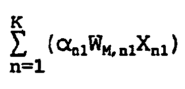
a second adder for outputting
- According to the present invention in a first aspect there is provided a spreading method comprising generating a first signal, a, based on at least a first input, a first code and a first gain; generating a second signal, b, based on at least a second input, a second code and a second gain, wherein the first and second codes are Hadamard code sequences; receiving a first sequence of sequence elements, the sequence elements in the first sequence alternating between a first value and a second value, the first value being different from the second value; receiving a second sequence SC comprising at least a first element having the first value and a second element having the second value; outputting SC·a-SC·b·d, wherein d is a third signal that is a multiplication of the first sequence of sequence elements by a third sequence P; outputting SC·b+SC·a·d; generating filtered outputs by processing the outputted SC·a-SC·b·d and SC·b+SC·a·d through one or more pulse shaping filters; generating modulated signals by multiplying the filtered outputs with carrier waves; and transmitting the modulated signals through an antenna.
- According to the present invention in a second aspect there is provided a spreading apparatus comprising a first signal generator configured to generate a first signal, a, based on at least a first input, a first code and a first gain; a second signal generator configured to generate a second signal, b, based on at least a second input, a second code and a second gain; a first sequence receiving unit configured to receive a first sequence of sequence elements alternating between a first value and a second value, the first value being different from the second value; a second sequence receiving unit configured to receive a second sequence SC comprising at least a first element having the first value and a second element having the second value; a first output unit configured to output SC·a-SC·b·d wherein d is a third signal that is a multiplication of the first sequence of sequence elements by a third sequence P; a second output unit configured to output SC·b+SC·a·d; a first pulse shaping filter coupled to the first output unit and configured to generate a first filtered output by processing the outputted SC·a-SC·b·d; a second pulse shaping filter coupled to the second output unit and configured to generate a second filtered output by processing SC·b+SC·a·d; a first modulator coupled to the first pulse shaping filter and configured to generate a modulated signal by multiplying the first filtered output with a first carrier wave; a second modulator coupled to the second pulse shaping filter and configured to generate a modulated signal by multiplying the second filtered output with a second carrier wave; and an antenna configured to transmit the first and second modulated signals.
- Additional advantages, objects and other features of the invention will be set forth in part in the description which follows and in part will become apparent to those having ordinary skill in the art upon examination of the following or may be learned from practice of the invention. The objects and advantages of the invention may be realized and attained as particularly pointed out in the appended claims.
- The present invention will become more fully understood from the detailed description given hereinbelow and the accompanying drawings which are given by way of illustration only, and thus are not limitative of the present invention, and wherein:
-
Figure 1 is a block diagram illustrating a conventional multichannel complex spreading method of a CDMA (Code Division Multiple Access) ONE method; -
Figure 2A is a view illustrating a constellation plot of a conventional CDMA ONE method; -
Figure 2B is a view illustrating a maximum open point after the actual shaping filter ofFigure 2A ; -
Figure 3A is a view illustrating a constellation plot of a conventional ETRI version 1.0 method; -
Figure 3B is a view illustrating a maximum open point after the actual pulse shaping filter ofFigure 3A ; -
Figure 4 is a block diagram illustrating a multichannel orthogonal complex spreading apparatus according to the present invention; -
Figure 5A is a circuit diagram illustrating the complex multiplexor ofFigure 4 ; -
Figure 5B is a circuit diagram illustrating the summing unit and spreading unit ofFigure 4 ; -
Figure 5C is a circuit diagram illustrating another embodiment of the spreading unit ofFigure 4 ; -
Figure 5D is a circuit diagram illustrating of the filter and modulator ofFigure 4 ; -
Figure 6A is a view illustrating a constellation plot of an OCQPSK using the apparatus offigure 4 ; -
Figure 6B is a view illustrating a maximum open point after the actual pulse shaping filter ofFigure 6A ; -
Figure 7 is a view illustrating a power peak occurrence statistical distribution characteristic with respect to an average power; -
Figure 8 is a view illustrating an orthogonal Hadamard sequence; -
Figure 9 is a circuit diagram illustrating a multichannel permutated orthogonal complex spreading apparatus suitable for understanding the invention; -
Figure 10 is a circuit diagram illustrating the complex multiplier; -
Figure 11 is a circuit diagram illustrating a multichannel permutated orthogonal complex spreading apparatus for a voice service; -
Figure 12 is a circuit diagram illustrating a multichannel permutated orthogonal complex spreading apparatus having a high quality voice service and a low transmission rate; -
Figure 13A is a circuit diagram illustrating a multichannel permutated orthogonal complex spreading apparatus for a QPSK having a high transmission rate ; -
Figure 13B is a circuit diagram illustrating a multichannel permutated orthogonal complex spreading apparatus for a data having a high transmission rate ; -
Figure 14A is a circuit diagram illustrating a multichannel permutated orthogonal complex spreading apparatus for a multimedia service having a QPSK data ; -
Figure 14B is a circuit diagram illustrating a multichannel permutated orthogonal complex spreading apparatus for a multimedia service; -
Figure 15A is a phase trajectory view of an OCQPSK using the apparatus ofFigure 4 ; -
Figure 15B is a phase trajectory view of a POCQPSK using the apparatus ofFigure 9 ; and -
Figure 15C is a phase trajectory view of a complex spreading method according to the present invention. - The complex summing unit and complex multiplier according to the present invention will be explained with reference to the accompanying drawings. In the present invention, two complexes (a+jb) and (c+jd) are used, where a, b, c and d represent predetermined real numbers.
- A complex summing unit outputs (a+c)+j(b+d), and a complex multiplier outputs ((axc)-(bxd))+j((bxc)+(axd)). Here, a spreading code sequence is defined as SC, an information data is defined as Xn1, and Xn2, a gain constant is defined as αn1 and αn2, and an orthogonal Hadamard sequence is defined as WM, n1, WM, n2, WM, n3, WM, n4, WM,I, WM,Q, where M represents a MxM Hadamard matrix, and n1, n2, n3 and n4 represents index of a predetermined vector of the Hadamard matrix. For example, n3 represents a Hadamard vector which is a third vector value written into the n-th block like the n-
th block 100n ofFigure 4 . The Hadamard M represents a Hadamard matrix. For example, if the matrix W has values of 1 and -1, in the WTxW, the main diagonal terms are M, and the remaining products are zero. Here, T represents a transpose. - The data Xn1, Xn2, WM, n1, WM, n2, WM, n3, WM, n4, WM, I, and WM, Q, and SC are combined data consisting of +1 or -1, and αn1, and αn2 represent real number.
-
Figure 4 is a block diagram illustrating a multichannel orthogonal complex spreading apparatus according to the present invention. - As shown therein, there is provided a plurality of
complex multipliers 100 through 100n in which a data of a predetermined channel is multiplied by a gain and orthogonal Hadamard sequence, and a data of another channel is multiplied by the orthogonal Hadamard sequence for thereby complex-summing two channel data, the orthogonal Hadamard sequence of the complex type is multiplied by the complex-summed data, and the data of other two channels are complex-multiplied in the same manner described above. A summingunit 200 sums and outputs the output signals from thecomplex multipliers 100 through 100n. A spreadingunit 300 multiplies the output signal from the summingunit 200 with a predetermined spreading code SC for thereby spreading the signal. Apulse shaping filter 400 filters the data spread by the spreadingunit 300. Amodulation wave multiplier 500 multiplies the output signal from thefilter 400 with a modulation carrier wave and outputs the modulated data through an antenna. - As shown in
Figure 4 , the firstcomplex multiplier 100 complex-sums α11WM,11X11 which is obtained by multiplying the orthogonal Hadamard sequence WM,11 with the data X11 of one channel and the gain α11, and α2 WM,12X12, which is obtained by multiplying the orthogonal Hadamard sequence WM,12 with the data X12 of another channel and the gain α12 and complex-multiplies α11WM,11X11 + jα 12 W M, 12 X 12 and the complex-type orthogonal sequence WM,13X11+jWM,14 using thecomplex multiplier 100. - In addition, the n-th
complex multiplier 100n complex-sums αn1WM,n1Xn1 which is obtained by multiplying the orthogonal Hadamard sequence WM,n1 with the data Xn1 of another channel and the gain αn1 and αn2WM,n2Xn2 which is obtained by multiplying the orthogonal Hadamard sequence WM,n2 with the data Xn2 of another channel and the gain αn2 and complex-multiplies αn1WM,n1Xn1 + jαn2WM,n2Xn2 and the complex-type orthogonal sequence WM,n3X11+jWM,n4 using thecomplex multiplier 100n. - The complex multiplication data outputted from the n-number of the complex multipliers are summed by the summing
unit 200, and the spreading code SC is multiplied and spread by the spreadingunit 300. The thusly spread data are filtered by thepulse shaping filter 600, and the modulation carried ej2nfct is multiplied by themultiplier 700, and then the function Re{*} is processed, and the real data s(t) is outputted through the antenna. Here, Re{*} represents that a predetermined complex is processed to a real value through the Re{*} function. - The above-described function will be explained as follows:

where K represents a predetermined integer greater than or equal to 1, n represents an integer greater than or equal to 1 and less than K and is identical with each channel number of the multichannel. - Each of the
complex multipliers 110 through 100n is identically configured so that two different channel data are complex-multiplied. - As shown in
Figure 5A , one complex multiplier includes a first multiplier 101 for multiplying the data X11 by the orthogonal Hadamard sequence WM,11, a second multiplier for multiplying the input signal from the first multiplier by the gain α11, a third multiplier 103 for multiplying the data X12 of the other channel by another orthogonal Hadamard sequence WM,12, a fourth multiplier 104 for multiplying the output signal from the third multiplier 103 by the gain α12, fifth and sixth multipliers 105 and 106 for multiplying the output signals α11WM,11X11 from the second multiplier 102 and the output signals α12WM,12X12 from the fourth multiplier 102 by the orthogonal Hadamard sequence WM,13, respectively, seventh and eighth multipliers 107 and 108 for multiplying the output signal α11WM,11X11 from the second multiplier 102 and the output signal α12WM,12X12 from the fourth multiplier 102 by the orthogonal Hadamard sequence WM,14, sequentially, a first adder 109 for summing the output signal (+ac) from the fifth multiplier 105 and the output signal (-bd) from the eighth multiplier 108 and outputting in-phase information (ac-bd), and a second adder 110 for summing the output signal (bc) from the sixth multiplier 106 and the output signal (ad) from the seventh multiplier 107 and outputting the quadrature-phase information (bc+ad). - Therefore, the first and
second multipliers fourth multipliers sixth multipliers sixth multipliers first adder 109 computes (α11WM,11X11WM,13)-(α12WM,12X12WM,14) (=ac-bd), namely, α12WM,12X12WM,14 is subtracted from α 11 W M,11 X 11 WM,13. In addition, thesecond adder 110 computes (α11WM,11X11WM,14) + ( α12WM,12X12WM,13) (ad+bc), namely, α11WM,11X11WM,14 (=ad) is added with α12WM,12X12WM,13(=bc). -
Figure 4 illustrates the firstcomplex multiplier 100 which is configured identically with the n-thcomplex multiplier 100n. Assuming that α11WM,11X11 is "a", α12WM,12X12 is "b", the orthogonal Hadamard sequence WM,13 is "c", and the orthogonal Hadamard sequence WM,14 is "d", the expression " (a+jb) (c+jd) = ac-bd+j (bc+ad) " is obtained. Therefore, the signal outputted from the firstcomplex multiplier 100 becomes the in-phase information "ac-bd" and the quadrature-phase information "bc+ad". - In addition,
Figure 5B is a circuit diagram illustrating the summing unit and spreading unit ofFigure 4 , andFigure 5C is a circuit diagram illustrating another embodiment of the spreading unit ofFigure 4 . - As shown therein, the summing
unit 200 includes a first summingunit 210 for summing the in-phase information A1(=(ac-bd), ..., An outputted from a plurality of complex multipliers, and a second summingunit 220 for summing the quadrature-phase information B1(=bc+ad) outputted from the complex multipliers. - The spreading
unit 300 includes first andsecond multipliers first adder 210 and thesecond adder 220 of the summingunit 200 by the spreading sequence SC, respectively. Namely, the signals are spread to the in-phase signal (I channel signal) and the quadrature-phase signal (Q channel signal) using one spreading code SC. - In addition, as shown in
Figure 5C , the spreadingunit 300 includes first andsecond multipliers second adders unit 200 by the spreading sequence SC1, third andfourth multipliers second adders first adder 350 for summing the output signal (+) from thefirst multiplier 310 and the output signal (-) from thethird multiplier 330 and outputting an I channel signal, and a second summingunit 360 for summing the output signal (+) from thesecond multiplier 320 and the output signal (+) from thefourth multiplier 340 and outputting a Q channel signal. - Namely, in the summing
unit 200, the in-phase information and the quadrature-phase information of the n-number of the complex multipliers are summed by the first and second summingunits unit 300, the in-phase information summing value (g) and the quadrature phase information summing value (h) from the summingunit 200 are multiplied by the first spreading code SC1 (1) by the first andsecond multipliers unit 200 are multiplied by the second spreading code SC2(m) by the third andfourth multipliers first adder 350 computes gl-hm in which hm is subtracted from gl, and thesecond adder 360 computes hl+gm in which hl is added by gm. - As shown in
Figure 5D , thefilter 400 includes first and secondpulse shaping filters Figure 5B and5C and the Q channel signal which is the quadrature phase information signal. Themodulation unit 500 includes first andsecond multipliers pulse shaping filters adder 530 for summing the output signals from themultipliers - Here, the orthogonal Hadamard sequences may be used as a Walsh code or other orthogonal code.
- For example, from now on, the case that the orthogonal Hadamard sequence is used for the 8x8 Hadamard matrix shown in
Figure 8 will be explained. -
Figure 8 illustrates an example of the Hadamard (or Walsh) code. Namely, the case that the sequence vector of a k-th column or row is set to Wk-1 based on the 8x8 Hadamard matrix is shown therein. In this case, if k is 1, Wk-1 represents W0 of the column or row, and if k is 5, Wk-1 represents W4 of the column or row. - Therefore, in order to enhance the efficiency of the apparatus of
figure 4 , the orthogonal Hadamard sequence which multiplies each channel data is determined as follows. - In the MxM Hadamard matrix, the sequence vector of the k-th column or row is set to Wk-1, and WM,n1=W0,WM,n2=W2p (where p represents a predetermined number of (M/2)-1), and WM,n3=W2n-2, WM,n4=W2n-1 (where n represents the number of n-th blocks), and αn1W0Xn1+jαn2W2pXn2 and W2n-2+jW2n-1.
- The case that only first complex multiplier is used in the apparatus of
Figure 4 , namely, the data of two channels are complex-multiplied will be explained. In the MxM (M=8) Hadamard matrix, if the k-th column or row sequence vector is set to Wk-1, it is possible to determine WM,11=W0, WM,12=W2, or WM,12=W4, and WM,13=W0, WM,14=W1. In addition, it is possible to complex-multiply α11W0X11+jα12W2X12 or α11W0X11+jα12W4X12 and W0+jW1. - In the case that two complex multipliers shown in
Figure 4 are used, the second complex multiplier determines WM,21=W0, WM,22=W4, and WM,23=W2, and W M,24=W 3, so that it is possible to complex-multiply α21W0X21+jα22W4X22 and W2+jW3. - In addition, as shown in
Figure 5 , when the spreading is implemented by using the spreading code SC, one spreading code may be used, and as shown inFigure 5C , two spreading codes SC1 and SC2 may be used for thereby implementing the spreading operation. - The orthogonal Hadamard sequence directed to multiplying each channel data may be determined as follows.
- The combined orthogonal Hadamard sequence may be used instead of the orthogonal Hadamard sequence for removing a predetermined phase dependency based on the interference generated in the multiple path type of self-signal and the interference generated by other users.
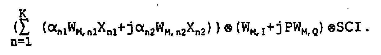
- For example, in the case of two channels, when the sequence vector of the k-th column or row is set to Wk-1 in the MxM (M=8) Hadamard matrix, and the sequence vector of the m-th column or row is set to Wm, the first M/2 or the last M/2 is obtained based on the vector Wk-1, and the last M/2 or the first M/2 is obtained based on Wm-1, so that the combined orthogonal Hadamard vector is set to Wk-1//m-1, and WM,11=W0, WM,12=W4//1, WM,1=W0, WM,Q=W1/4 are determined, so that it is possible to complex-multiply α11W0X11+ja12W4//1X12 and W0+jPW1//4.
- In the case of three channels, the sequence vector of the k-th column or row is set to Wk-1 based on the MxM (M=8) Hadamard matrix, and the sequence vector of the m-th column or row is set to WM, so that the first M/2 or the last M/2 is obtained from the vector Wk-1, and the last M/2 or the first M/2 is obtained from Wm-1, and the combined orthogonal Hadamard vector is set to Wk-1//m-1, and the summed value of α11W0X11+jα12W4//1X12 and α21W2X21 and W0 +jPW1//4 are complex-multiplied based on WM,11=W0, WM,12=W4//1, W M,21=W 2' and WM,I=W 0, WM,Q=W1//4.
- In addition, in the case of two channels, when the sequence vector of the k-th column or row of the MxM (M=8) Hadamard vector matrix is set to Wk-1, and the sequence vector of the m-th column or row is set to Wm, the first M/2 or the last M/2 is obtained from the vector Wk-1, and the last M/2 or the first M/2 is obtained from Wm-1, so that the combined orthogonal Hadamard vector is set to Wk-1//m-1, and the summed value of α11W0X11+jα12W2//1X12 and W0+jPW1//2 are complex-multiplied based on WM,11=W0, WM,12=W2//1, and WM,I=W0, WM,Q=W1//2.
- In addition, in the case of three channels, when the sequence vector of the k-th column or row of the MxM (M=8) Hadamard vector matrix is set to Wk-1, and the sequence vector of the m-th column or row is set to Wm, the first M/2 or the last M/2 is obtained from the vector Wk-1, and the last M/2 or the first M/2 is obtained from Wm-1, so that the combined orthogonal Hadamard vector is set to Wk-1//m-1, and the summed value of α11W0X11+jα12W2//1X12 and α21W4X21 and W0+jpW1//2 are complex-multiplied based on WM,11=W0, W M,12=W 2//1, W M,21=W 4, and W M,I= W0, WM,Q=W1//2.
- Here, so far the cases of two channels and three channels were explained. The cases of two channels and three channels may be selectively used in accordance with the difference of the impulse response characteristic difference of the pulse shaping bandpass filter.
-
Figure 6A is a view illustrating a constellation plot of the OCQPSK using the apparatus ofFigure 4 ,Figure 6B is a view illustrating a maximum eye-opening point after the actual pulse shaping filter ofFigure 6A -, andFigure 7 is a view illustrating a power peak occurrence statistical distribution characteristic with respect to an average power between the OCQPSK using the apparatus ofFigure 4 and the conventional CDMA ONE and version ETRI 1.0. As shown therein, the embodiment ofFigure 6A is similar with that ofFigure 2A . However, there is a difference in the point of the maximum eye-opening point after the actual pulse shaping filter. Namely, infigure 6B , the range of the upper and lower information (Q channel) and the left and right information (I channel) are fully satisfied. This causes the difference of the statistical distribution of the peak power-to-average power. -
Figure 7 illustrates the peak power-to-average power ratio obtained based on the result of the actual simulation. - In order to provide the identical conditions, the power level of the control or signal channel is controlled to be the same as the power level of the communication channel (Fundamental channel, supplemental channel or the In-phase channel and the Quadrature channel), and the power level of the pilot channel is controlled to be lower than the power level of the communication channel by 4dB. In the above-described state, the statistical distributions of the peak power-to-average power are compared.
- In the case of OCQPSK using the apparatus of
Figure 4 , the comparison is implemented using the firstcomplex multiplier 100 and the n-thcomplex multiplier 100n shown inFigure 4 . Thefirst block 100 is implemented based on WM,11=W0, WM,12=W4, W M,13=W 0, and WM,14 =W1 , and the n-th block 100n is implemented based on WM,n1=W0, WM,n2=W4, WM,n3=W2, and W M,n4=W 3. In addition, the SCI is used as the SC1 for the spreading code. In this case, the SC2 is not used. - In the case of OCQPSK, the probability that the instantaneous power exceeds the average power value (0 dB) by 4 dB is 0.03%, and in the case of CDMA ONE, the same is 0.9%, and in the case of the ETRI version 1.0, the same is 4%. Therefore, in the present invention, the system using the CDMA technique has very excellent characteristic in the peak to average power ratio sense, and the method which eliminates the cross talk problem.
-
Figure 9 illustrates a permutated orthogonal complex spreading modulation (POCQPSK) as an example suitable for understanding the invention. - As shown therein, one or a plurality of channels are combined and complex-multiplied by the permutated orthogonal Hadamard code and then are spread by the spreading code.
- As shown therein, there are provided first and second Hadamard sequence multipliers 600 and 700 for allocating the multichannel to a predetermined number of channels, splitting the same into two groups and outputting αn1WM,n1Xn1 which is obtained by multiplying the data Xn1 of each channel by the gain αn1 and the orthogonal Hadamard sequence WM,n1, a first adder 810 for outputting


- Here, the construction of the spreading
unit 300, thefilter 400 and themodulator 500 is the same as the embodiment ofFigure 4 except for the following construction. Namely, comparing to the embodiment ofFigure 4 , in the construction ofFigure 9 , the multiplication of the complex type orthogonal Hadamard sequence performed by thecomplex multipliers 100 through 100n are separated and connected in the rear portion of the summing unit, and the channel-wise multiplication by the complex type orthogonal Harmard sequence is not implemented. Namely, the two group summed signal is multiplied by the complex type orthogonal Hadamard sequence. - The first orthogonal
Hadamard sequence multiplier 600 outputs
first adder 810 by summing α11WM,11X11 which is obtained by thefirst adder 810 by multiplying the orthogonal Hadamard sequence WM,11 by the first data X11 of the first block and the 11gain α , respectively, α21WM,21X21 which is obtained by multiplying the orthogonal Hadamard sequence WM,21 by the second data X21 of the first block and the gain α21, respectively, and αn1WM,n1Xn1 which is obtained by multiplying the orthogonal Hadamard sequence WM,n1 by the n-th data Xn1 of the first block and the gain αn1. - The second orthogonal
Hadamard sequence multiplier 700 outputs
second adder 820 by summing α12WM,12X12 which is obtained by multiplying the orthogonal Hadamard sequence WM,12 by the first data X12 of the second block and the gain α12, respectively, α22WM,22X22 which is obtained by multiplying the orthogonal Hadamard sequence WM,22 by the second data X22 of the second block and the gain α22, respectively, and αn2WM,n2Xn2 which is obtained by multiplying the orthogonal Hadamard sequence WM,n2 by the n-th data Xn2 of the second block and the gain αn2. Here, the block represents one group split into 1 group. - The signal outputted from the
first adder 810 forms an in-phase data, and the signal outputted from thesecond adder 820 forms an quadrature phase data and outputs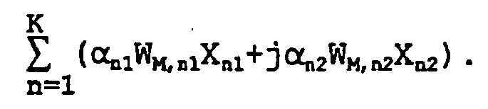
complex multiplier 900 multiplies the complex output signals from the first andsecond adders second adders - The spreading
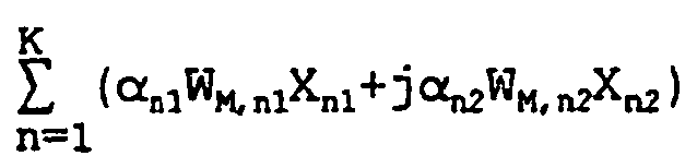
unit 300 multiplies the output signal from thecomplex multiplier 900 by the spreading code SCI and spreads the same. The thusly spread signals are filtered by thepulse shaping filters modulation multipliers - Namely, the following equation is obtained.
where K represents an integer greater than or equal to 1. -
Figure 10 illustrates an embodiment that two channel data are complex-multiplied. A channel data X11 is allocated to the first orthogonalHadamard sequence multiplier 600 and another channel data X12 is allocated to the second orthogonalHadamard sequence multiplier 700. - Here, the orthogonal Hadamard sequence multiplier includes a
first multiplier 610 for multiplying the first data X11 by the gain q1, asecond multiplier 611 for multiplying the output signal from thefirst multiplier 610 by the orthogonal Hadamard sequence WM,11, athird multiplier 710 for multiplying the second data X12 by the gain α12, and afourth multiplier 711 for multiplying the output signal from thethird multiplier 710 by the orthogonal Hadamard sequence WM,12. At this time, since one channel is allocated to one group, the summing unit is not used. - The
complex multiplier 900 includes fifth andsixth multipliers second multiplier 611 and the output signal α12WM,12X12 from thefourth multiplier 711 by the orthogonal Hadamard sequence WM,I, seventh andeighth multipliers second multiplier 611 and the output signal α12WM,12X12 from thefourth multiplier 711 by the permutated orthogonal Hadamard sequence PWM,Q, afirst adder 905 for summing the output signal (+ac) from thefifth multiplier 901 and the output signal (-bd) from theseventh multiplier 903 and outputting an in-phase information (ac-bd), and asecond adder 906 for summing the output signal (bc) from thesixth multiplier 902 and the output signal (ad) from theeighth multiplier 904 and outputting an quadrature phase information (bc+ad). - Therefore, the first and
second multipliers fourth multipliers sixth multipliers - The seventh and
eighth multipliers - In addition, the
first adder 905 obtains (α11WM,11X11WM,I)-(α12WM,12X12PWM,Q) (=ac-bd), namely, α12WM,12X12PWM,Q(bd) is subtracted from α11W M,11X 11WM,I (=ac), and thesecond adder 906 obtains (α11WM,11X11 PWM,Q) + (α12WM,12X12WM,I) (=ad+bc), namely, (α11WM,11X11PWM,Q) (=ad) is summed by (α12WM,12X12WM,I) (bc) . -
Figure 10 illustrates thecomplex multiplier 900 shown inFigure 9 . Assuming that α11WM,11X11 is "a", α12WM,12X12 is "b", the orthogonal Hadamard sequence WM,I is "c", and the permutated orthogonal Hadamard sequence PWM,Q is "d", since (a+jb) (c+jd)=ac-bd+j (bc+ad), the signal from thecomplex multiplier 900 becomes the in-phase information ac-bd and the quadrature phase information bc+ad. - The in-phase data and the quadrature phase data are spread by the spreading
unit 300 based on the spreading code (for example, PN code). In addition, the I channel signal which is the in-phase information and the Q channel signal which is the quadrature phase information signal are filtered by the first and secondpulse shaping filters second multipliers pulse shaping filters multipliers adder 530 which outputs S(t). - In the embodiment as shown in
Figure 9 , identically to the embodiment as shown inFigure 4 , for the orthogonal Hadamard sequence, the Walsh code or other orthogonal code may be used. In addition, in the orthogonal Hadamard sequence of each channel, the sequence vector of the k-th column or row is set to Wk-1 in the MxM Hadamard matrix. Therefore, αn1W0Xn1+jαn2W2pXn2 and W 0+jPW1 are complex-multiplied based on WM,n1=W0, WM,n2=W2p (where p represents a number in a range from 0 to (M/2)-1. - The orthogonal Hadamard sequence is allocated to each channel based on the above-described operation, and if there remain other channels which are not allocated the orthogonal Hadamard sequence by the above-described operation, and if there remain other channel which are not allocated the orthogonal Hadamard sequence by the above-described operation, then any row or column vector from the Hamard matrix can be selected.
Figure 11 illustrates an embodiment of the POCQPSK for the voice service. In this case, two channels, namely, the pilot channel and the data of traffic channels are multiplied by the gain and orthogonal .Hadamard sequence, and two channel signals are inputted into thecomplex multiplier 900 in the complex type, and the orthogonal Hadamard sequence of the complex type is multiplied by thecomplex multiplier 900. -
Figure 12 illustrates the construction of a data service having a good quality voice service and low transmission rate. In this case, the pilot channel and signaling channel are allocated to the first orthogonalHadamard sequence multiplier 700, and the traffic channel is allocated to the second orthogonalHadamard sequence multiplier 700. -
Figure 13A illustrates the construction for a data service of a high transmission rate. As shown therein, the data transmitted at a rate of R bps has the QPSK data type and are transmitted at R/2 bps through the serial to parallel converter. As shown inFigure 13B , the system may be constituted so that the input data (traffic 1 and traffic 2) have the identical gains (α31=α12). Here, when the data having high transmission rate are separated into two channels, the gain allocated to each channel should be determined to the identical gain for thereby eliminating the phase dependency. -
Figures 14A and14B illustrate the construction of the multichannel service. In this case, the data (traffic) having a high transmission rate is converted into the QPSK data for R/2 bps through the serial to parallel converter and then is distributed to the first orthogonalHadamard sequence multiplier 600 and the secondHadamard sequence multiplier 700, and three channels are allocated to the first orthogonalHadamard sequence multiplier 600 and two channels are allocated to the second orthogonalHadamard sequence multiplier 700. - As shown in
Figure 14B , the serial to parallel converter is not used, and when the data (traffic) is separated into two channel data (Traffic 1) and (traffic 2) and then is inputted, the gain adapted to each channel adapts the identical gains (α31=α12). -
Figure 15A is a phase trajectory view of an OCQPSK using the apparatus ofFigure 4 ,Figure 15B is a phase trajectory view of a POCQPSK using the exemplary apparatus ofFig. 9 , andFigure 15C is a phase trajectory view of a complex spreading method according to PN complex spreading method of the present invention. - As shown therein, when comparing the embodiments of
Figure 15A, 15B and15C , the shapes of the trajectories and the zero points are different. In a view of the power efficiency, there is also a difference. Therefore, the statistical distribution of the peak power-to-average power ratio is different. -
Figure 7 illustrates a characteristic illustrating a statistical distribution of a peak power-to-average power ratio of the CDMA ONE method compared to the OCQPSK method and the POSQPSK. - In order to provide the identical condition, the power level of the signal channel is controlled to be the same as the power level of the communication channel, and the power level of the pilot channel is controlled to be lower than the power level of the communication channel by 4dB, and then the statistical distribution of the peak power-to-average power ratio is compared.
- In the case of the POCQPSK according to the present invention, in the
first block 600 ofFigure 9 , WM,11=W0, and WM,21=W2 are implemented, and in thesecond block 700, WM,12=W4, and WM,I=W0 and WM,Q=W1 are implemented. For the value of P, the spreading code is used so that consecutive two sequences have the identical value. - For example, the probability that the instantaneous power exceeds the average power value (0dB) by 4dB is 0.1% based on POCQPSK, and the complex spreading method is 2%. Therefore, in view of the power efficiency, the method adapting the CDMA technique according to the present invention is a new modulation method having excellent characteristic.
- As described above, in the OCQPSK, the first data and the second data are multiplied by the gain and orthogonal code, and the resultant values are complex-summed, and the complex summed value is complex-multiplied by the complex type orthogonal code. The method that the information of the multichannel of the identical structure is summed and then spread is used. Therefore, this method statistically reduces the peak power-to-average power ratio to the desired range.
- In addition, in the POCQPSK according to the present invention, the data of the first block and the data of the second block are multiplied by the gain and the orthogonal code, respectively, and the permutated orthogonal spreading code of the complex type is complex-multiplied and then spread. Therefore, this method statistically reduces the peak power-to-average power ratio to the desired range, and it is possible to decrease the phase dependency based in the multichannel interference and the multiuser interference using the combined orthogonal Hadamard sequence.
- Although the preferred embodiments of the present invention have been disclosed for illustrative purposes, those skilled in the art will appreciate that various modifications, additions and substitutions are possible, without departing from the scope of the invention as recited in the accompanying claims.
Claims (10)
- A spreading method comprising
generating a first signal, a, based on at least a first input, a first code and a first gain;
generating a second signal, b, based on at least a second input, a second code and a second gain, wherein the first and second codes are Hadamard code sequences;
receiving a first sequence of sequence elements, the sequence elements in the first sequence alternating between a first value and a second value, the first value being different from the second value;
receiving a second sequence SC comprising at least a first element having the first value and a second element having the second value;
outputting SC·a-SC·b·d, wherein d is a third signal that is a multiplication of the first sequence of sequence elements and a third sequence P;
outputting SC·b+SC·a·d;
generating filtered outputs by processing the outputted SC·a-SC·b·d and SC·b+SC·a·d through one or more pulse shaping filters (400);
generating modulated signals by multiplying the filtered outputs with carrier waves; and
transmitting the modulated signals through an antenna. - The method of Claim 1 wherein the first sequence of sequence elements is W1.
- The method of Claim 1 or Claim 2 wherein the second sequence is a first PN code.
- The method of Claims 1, 2 or 3 wherein the first code consists of elements, one or more of the elements of the first code having the first value and the remaining elements of the first code having the second value, wherein for the (2M-1)th element of the first code, the value of the (2M-1)th element of the first code is the same as the (2M)th element of the first code, where M is a series of sequential positive integers beginning at 1.
- The method of Claim 4 wherein the second code consists of elements one or more elements of the second code having the first value and the remaining elements of the second code having the second value wherein for the (2K-1)th element of the second code the value of the (2K-1)th element of the second code is the same as the value of the (2K)th element of the second code where K is a series of sequential positive integers beginning at 1.
- A spreading apparatus comprising
a first signal generator (101,102) configured to generate a first signal, a, based on at least a first input, a first code and a first gain;
a second signal generator (103,104) configured to generate a second signal, b, based on at least a second input, a second code and a second gain;
a first sequence receiving unit configured to receive a first sequence of sequence elements alternating between a first value and a second value, the first value being different from the second value;
a second sequence receiving unit (300) configured to receive a second sequence SC comprising at least a first element having the first value and a second element having the second value;
a first output unit (300, 301) configured to output SC·a-SC·b·d wherein d is a third signal that is a multiplication of the first sequence of sequence elements and a third sequence P;
a second output unit (300, 302) configured to output SC·b+SC·a·d;
a first pulse shaping filter (400, 410) coupled to the first output unit and configured to generate a first filtered output by processing the outputted SC·a-SC·b·d;
a second pulse shaping filter (400, 420) coupled to the second output unit and configured to generate a second filtered output by processing SC·b+SC·a·d;
a first modulator (500, 510) coupled to the first pulse shaping filter (400, 410) and configured to generate a modulated signal by multiplying the first filtered output with a first carrier wave;
a second modulator (500, 520) coupled to the second pulse shaping filter (400, 420) and configured to generate a modulated signal by multiplying the second filtered output with a second carrier wave; and
an antenna configured to transmit the first and second modulated signals. - The apparatus of Claim 6 wherein the sequence of sequence elements is W1.
- The apparatus of Claim 6 or Claim 7 wherein the second sequence is a PN code.
- The apparatus of any of Claims 6, 7 or 8 wherein the first code consists of elements one or more of the elements of the first code having the first value and the remaining elements of the first code having the second value wherein for the (2K-1)th element of the first code the value of the (2K-1)th element of the first code is the same as the value of the (2K)th element of the first code, wherein K is a series of sequential positive integers beginning at 1.
- The apparatus of Claim 9 wherein the first code consists of elements, one or more of the elements of the first code having the first value and the remaining elements of the first code having the second value, wherein for the (2M-1)th element of the first code, the value of the (2M-1)th element of the first code is the same as the value of the (2M)th element of the first code, where M is a series of sequential positive integers beginning at 1.
Priority Applications (2)
| Application Number | Priority Date | Filing Date | Title |
|---|---|---|---|
| EP20100075559 EP2262141A1 (en) | 1997-12-02 | 1998-10-02 | Orthogonal complex spreading method for multichannel and apparatus thereof |
| EP20100075378 EP2251998B1 (en) | 1997-12-02 | 1998-10-02 | Orthogonal complex spreading method for multichannel and apparatus thereof |
Applications Claiming Priority (3)
| Application Number | Priority Date | Filing Date | Title |
|---|---|---|---|
| KR19970065375 | 1997-12-02 | ||
| KR1019980011923A KR100269593B1 (en) | 1997-12-02 | 1998-04-04 | Orthogonal complex spreading based modulation method for multichannel transmission |
| EP19980308056 EP0921652B1 (en) | 1997-12-02 | 1998-10-02 | Orthogonal complex spreading method for multichannel and apparatus thereof |
Related Parent Applications (2)
| Application Number | Title | Priority Date | Filing Date |
|---|---|---|---|
| EP19980308056 Division EP0921652B1 (en) | 1997-12-02 | 1998-10-02 | Orthogonal complex spreading method for multichannel and apparatus thereof |
| EP98308056.5 Division | 1998-10-02 |
Related Child Applications (3)
| Application Number | Title | Priority Date | Filing Date |
|---|---|---|---|
| EP20100075378 Division EP2251998B1 (en) | 1997-12-02 | 1998-10-02 | Orthogonal complex spreading method for multichannel and apparatus thereof |
| EP10075378.9 Division-Into | 2010-09-02 | ||
| EP10075559.4 Division-Into | 2010-09-30 |
Publications (3)
| Publication Number | Publication Date |
|---|---|
| EP1816774A2 EP1816774A2 (en) | 2007-08-08 |
| EP1816774A3 EP1816774A3 (en) | 2008-04-02 |
| EP1816774B1 true EP1816774B1 (en) | 2012-11-21 |
Family
ID=26633222
Family Applications (10)
| Application Number | Title | Priority Date | Filing Date |
|---|---|---|---|
| EP20100075559 Withdrawn EP2262141A1 (en) | 1997-12-02 | 1998-10-02 | Orthogonal complex spreading method for multichannel and apparatus thereof |
| EP20070075395 Expired - Lifetime EP1816774B1 (en) | 1997-12-02 | 1998-10-02 | Orthogonal complex spreading method for multichannel and apparatus thereof |
| EP20070010769 Expired - Lifetime EP1819082B1 (en) | 1997-12-02 | 1998-10-02 | Orthogonal complex spreading method for multichannel and apparatus thereof |
| EP20040077916 Withdrawn EP1501224A3 (en) | 1997-12-02 | 1998-10-02 | Orthogonal complex spreading method for multichannel and apparatus thereof |
| EP20070075393 Expired - Lifetime EP1816773B1 (en) | 1997-12-02 | 1998-10-02 | Orthogonal complex spreading method for multichannel and apparatus thereof |
| EP20070010789 Expired - Lifetime EP1819083B1 (en) | 1997-12-02 | 1998-10-02 | Orthogonal complex spreading method for multichannel and apparatus thereof |
| EP20070010702 Expired - Lifetime EP1819081B1 (en) | 1997-12-02 | 1998-10-02 | Orthogonal complex spreading method for multichannel and apparatus thereof |
| EP20100075378 Expired - Lifetime EP2251998B1 (en) | 1997-12-02 | 1998-10-02 | Orthogonal complex spreading method for multichannel and apparatus thereof |
| EP20040077915 Withdrawn EP1499053A3 (en) | 1997-12-02 | 1998-10-02 | Orthogonal complex spreading method for multichannel and apparatus thereof |
| EP19980308056 Expired - Lifetime EP0921652B1 (en) | 1997-12-02 | 1998-10-02 | Orthogonal complex spreading method for multichannel and apparatus thereof |
Family Applications Before (1)
| Application Number | Title | Priority Date | Filing Date |
|---|---|---|---|
| EP20100075559 Withdrawn EP2262141A1 (en) | 1997-12-02 | 1998-10-02 | Orthogonal complex spreading method for multichannel and apparatus thereof |
Family Applications After (8)
| Application Number | Title | Priority Date | Filing Date |
|---|---|---|---|
| EP20070010769 Expired - Lifetime EP1819082B1 (en) | 1997-12-02 | 1998-10-02 | Orthogonal complex spreading method for multichannel and apparatus thereof |
| EP20040077916 Withdrawn EP1501224A3 (en) | 1997-12-02 | 1998-10-02 | Orthogonal complex spreading method for multichannel and apparatus thereof |
| EP20070075393 Expired - Lifetime EP1816773B1 (en) | 1997-12-02 | 1998-10-02 | Orthogonal complex spreading method for multichannel and apparatus thereof |
| EP20070010789 Expired - Lifetime EP1819083B1 (en) | 1997-12-02 | 1998-10-02 | Orthogonal complex spreading method for multichannel and apparatus thereof |
| EP20070010702 Expired - Lifetime EP1819081B1 (en) | 1997-12-02 | 1998-10-02 | Orthogonal complex spreading method for multichannel and apparatus thereof |
| EP20100075378 Expired - Lifetime EP2251998B1 (en) | 1997-12-02 | 1998-10-02 | Orthogonal complex spreading method for multichannel and apparatus thereof |
| EP20040077915 Withdrawn EP1499053A3 (en) | 1997-12-02 | 1998-10-02 | Orthogonal complex spreading method for multichannel and apparatus thereof |
| EP19980308056 Expired - Lifetime EP0921652B1 (en) | 1997-12-02 | 1998-10-02 | Orthogonal complex spreading method for multichannel and apparatus thereof |
Country Status (5)
| Country | Link |
|---|---|
| US (6) | US6222873B1 (en) |
| EP (10) | EP2262141A1 (en) |
| JP (1) | JP3094292B2 (en) |
| KR (1) | KR100269593B1 (en) |
| DE (4) | DE69838242T2 (en) |
Families Citing this family (84)
| Publication number | Priority date | Publication date | Assignee | Title |
|---|---|---|---|---|
| KR100269593B1 (en) * | 1997-12-02 | 2000-10-16 | 정선종 | Orthogonal complex spreading based modulation method for multichannel transmission |
| US7936728B2 (en) | 1997-12-17 | 2011-05-03 | Tantivy Communications, Inc. | System and method for maintaining timing of synchronization messages over a reverse link of a CDMA wireless communication system |
| US8175120B2 (en) | 2000-02-07 | 2012-05-08 | Ipr Licensing, Inc. | Minimal maintenance link to support synchronization |
| US9525923B2 (en) | 1997-12-17 | 2016-12-20 | Intel Corporation | Multi-detection of heartbeat to reduce error probability |
| US7394791B2 (en) | 1997-12-17 | 2008-07-01 | Interdigital Technology Corporation | Multi-detection of heartbeat to reduce error probability |
| US6222832B1 (en) | 1998-06-01 | 2001-04-24 | Tantivy Communications, Inc. | Fast Acquisition of traffic channels for a highly variable data rate reverse link of a CDMA wireless communication system |
| KR100381012B1 (en) | 1998-05-04 | 2003-08-19 | 한국전자통신연구원 | Random connection device for reverse common channel in cdma scheme and method therefor |
| US8134980B2 (en) | 1998-06-01 | 2012-03-13 | Ipr Licensing, Inc. | Transmittal of heartbeat signal at a lower level than heartbeat request |
| US7773566B2 (en) | 1998-06-01 | 2010-08-10 | Tantivy Communications, Inc. | System and method for maintaining timing of synchronization messages over a reverse link of a CDMA wireless communication system |
| US6711121B1 (en) * | 1998-10-09 | 2004-03-23 | At&T Corp. | Orthogonal code division multiplexing for twisted pair channels |
| CA2282780A1 (en) * | 1998-11-02 | 2000-05-02 | Zulfiquar Sayeed | A method and apparatus for achieving channel variability in spread spectrum communication systems |
| JP2000151557A (en) * | 1998-11-13 | 2000-05-30 | Nec Corp | Cdma communication apparatus |
| US6788728B1 (en) * | 1999-01-12 | 2004-09-07 | Sony Corporation | System and method for reducing peak-to-average ratio of the reverse link modulator in a CDMA phone system |
| US6611567B1 (en) * | 1999-01-29 | 2003-08-26 | Agere Systems, Inc. | Method and apparatus for pulse shaping |
| JP3362009B2 (en) * | 1999-03-01 | 2003-01-07 | シャープ株式会社 | Spread spectrum communication equipment |
| US7443906B1 (en) * | 1999-05-31 | 2008-10-28 | Electronics And Telecommunications Research Institute | Apparatus and method for modulating data message by employing orthogonal variable spreading factor (OVSF) codes in mobile communication system |
| US6556557B1 (en) * | 1999-06-02 | 2003-04-29 | At&T Corp. | Method and system for reducing of peak-to-average power ratio of transmission signals comprising overlapping waveforms |
| GB9922239D0 (en) * | 1999-09-20 | 1999-11-17 | Nokia Mobile Phones Ltd | A multiple access technique for mobile radio systems |
| JP3688166B2 (en) * | 1999-11-26 | 2005-08-24 | シャープ株式会社 | CDMA modulation method and apparatus |
| JP2001189711A (en) * | 1999-12-29 | 2001-07-10 | Agilent Technologies Japan Ltd | Device and method for displaying code domain power |
| JP2001223670A (en) | 2000-02-09 | 2001-08-17 | Nec Corp | Spread code generator and cdma communication unit using it, and spread code generating method used for them |
| US6904085B1 (en) * | 2000-04-07 | 2005-06-07 | Zenith Electronics Corporation | Multipath ghost eliminating equalizer with optimum noise enhancement |
| JP2002033716A (en) * | 2000-07-18 | 2002-01-31 | Sony Corp | CDMA spreading method and CDMA terminal device |
| KR100682118B1 (en) * | 2000-08-25 | 2007-02-12 | 에스케이 텔레콤주식회사 | An apparatus and method for eliminating multiple access interference in wireless local loop system based on code division multiple access method |
| US6847677B1 (en) * | 2000-09-29 | 2005-01-25 | Qualcomm, Incorporated | Method and apparatus for efficient Walsh covering and summing of signals in a communication system |
| US6745050B1 (en) * | 2000-10-23 | 2004-06-01 | Massachusetts Institute Of Technology | Multichannel multiuser detection |
| KR20020034775A (en) * | 2000-11-03 | 2002-05-09 | 김동인 | Method of Designing Multidimensional Signal and Algorithm for Removing Self-interference Thereof |
| US6956891B2 (en) * | 2000-11-15 | 2005-10-18 | Go-Cdma Limited | Method and apparatus for non-linear code-division multiple access technology |
| US8155096B1 (en) | 2000-12-01 | 2012-04-10 | Ipr Licensing Inc. | Antenna control system and method |
| KR100714046B1 (en) * | 2000-12-12 | 2007-05-04 | 주식회사 케이티 | Distributed measurement device and method for removing repetitive interference |
| US7551663B1 (en) * | 2001-02-01 | 2009-06-23 | Ipr Licensing, Inc. | Use of correlation combination to achieve channel detection |
| US6954448B2 (en) | 2001-02-01 | 2005-10-11 | Ipr Licensing, Inc. | Alternate channel for carrying selected message types |
| CA2867406C (en) | 2001-06-13 | 2016-08-02 | Intel Corporation | Transmittal of heartbeat signal at a lower level than heartbeat request |
| US7170952B2 (en) | 2001-07-02 | 2007-01-30 | Powerwave Technologies, Inc. | System and method for post filtering peak power reduction in communications systems |
| WO2003013040A1 (en) * | 2001-08-02 | 2003-02-13 | Morphics Technology, Inc. | Configurable terminal engine |
| US7095798B2 (en) | 2001-08-02 | 2006-08-22 | Powerwave Technologies, Inc. | System and method for post filtering peak power reduction in multi-carrier communications systems |
| KR100449546B1 (en) * | 2001-10-08 | 2004-09-21 | 주식회사 카서 | Code select cdma modulation and demodulation method and device thereof |
| KR100478255B1 (en) * | 2002-02-21 | 2005-03-25 | 공형윤 | Modulating and demodulating method for increasing the transmitting rate and improving the ber in the cdma communication system |
| US7660282B2 (en) | 2003-02-18 | 2010-02-09 | Qualcomm Incorporated | Congestion control in a wireless data network |
| US8150407B2 (en) | 2003-02-18 | 2012-04-03 | Qualcomm Incorporated | System and method for scheduling transmissions in a wireless communication system |
| US8391249B2 (en) | 2003-02-18 | 2013-03-05 | Qualcomm Incorporated | Code division multiplexing commands on a code division multiplexed channel |
| US7155236B2 (en) | 2003-02-18 | 2006-12-26 | Qualcomm Incorporated | Scheduled and autonomous transmission and acknowledgement |
| US20040160922A1 (en) | 2003-02-18 | 2004-08-19 | Sanjiv Nanda | Method and apparatus for controlling data rate of a reverse link in a communication system |
| US8023950B2 (en) | 2003-02-18 | 2011-09-20 | Qualcomm Incorporated | Systems and methods for using selectable frame durations in a wireless communication system |
| US8081598B2 (en) | 2003-02-18 | 2011-12-20 | Qualcomm Incorporated | Outer-loop power control for wireless communication systems |
| US8705588B2 (en) | 2003-03-06 | 2014-04-22 | Qualcomm Incorporated | Systems and methods for using code space in spread-spectrum communications |
| US7215930B2 (en) | 2003-03-06 | 2007-05-08 | Qualcomm, Incorporated | Method and apparatus for providing uplink signal-to-noise ratio (SNR) estimation in a wireless communication |
| US8477592B2 (en) | 2003-05-14 | 2013-07-02 | Qualcomm Incorporated | Interference and noise estimation in an OFDM system |
| US8489949B2 (en) | 2003-08-05 | 2013-07-16 | Qualcomm Incorporated | Combining grant, acknowledgement, and rate control commands |
| US8090857B2 (en) | 2003-11-24 | 2012-01-03 | Qualcomm Atheros, Inc. | Medium access control layer that encapsulates data from a plurality of received data units into a plurality of independently transmittable blocks |
| US7395290B2 (en) * | 2004-06-04 | 2008-07-01 | Agilent Technologies, Inc. | Digital filter and method thereof using frequency translations |
| PL1829312T3 (en) | 2004-12-23 | 2014-04-30 | Electronics & Telecommunications Res Inst | Apparatus for transmitting and receiving data to provide high-speed data comunication and method thereof |
| AU2011203042B2 (en) * | 2005-07-27 | 2012-02-23 | Qualcomm Atheros, Inc. | Managing spectra of modulated signals in a communication network |
| US8175190B2 (en) | 2005-07-27 | 2012-05-08 | Qualcomm Atheros, Inc. | Managing spectra of modulated signals in a communication network |
| US7729433B2 (en) * | 2006-03-07 | 2010-06-01 | Motorola, Inc. | Method and apparatus for hybrid CDM OFDMA wireless transmission |
| ES2302638B1 (en) * | 2006-12-21 | 2009-06-04 | Vicente Diaz Fuente | IMPROVED CODING AND DECODING METHOD WITH AT LEAST TWO PAIRS OF ORTOGONAL SEQUENCES. |
| CN101136888B (en) | 2007-05-18 | 2011-09-21 | 中兴通讯股份有限公司 | Modulation method to reduce signal peak-to-average power ratio |
| US7768457B2 (en) * | 2007-06-22 | 2010-08-03 | Vubiq, Inc. | Integrated antenna and chip package and method of manufacturing thereof |
| WO2009002464A2 (en) * | 2007-06-22 | 2008-12-31 | Vubiq Incorporated | System and method for wireless communication in a backplane fabric architecture |
| US8630383B2 (en) * | 2008-08-22 | 2014-01-14 | Alcatel Lucent | Communication system for transmitting sync-flags and pilot symbols and method thereof |
| US8385461B1 (en) | 2009-04-20 | 2013-02-26 | Vubiq, Inc. | On-off keying using vector modulation |
| US9893406B2 (en) | 2009-08-19 | 2018-02-13 | Vubiq Networks, Inc. | Method of forming a waveguide interface by providing a mold to form a support block of the interface |
| KR20120078697A (en) | 2009-08-19 | 2012-07-10 | 부비큐, 인코포레이티드 | Precision waveguide interface |
| CN102783065B (en) * | 2010-04-02 | 2014-11-19 | 富士通株式会社 | Apparatus and method for orthogonal cover code (OCC) generation, and apparatus and method for OCC mapping |
| US8693526B2 (en) * | 2011-02-16 | 2014-04-08 | Chester Wildey | Unipolar spread spectrum modulation for low computation and power cost signal multiplexing with application to fNIRS measurments |
| US9275540B2 (en) | 2012-02-06 | 2016-03-01 | Neocific, Inc. | Methods and apparatus for contingency communications |
| US9197302B2 (en) * | 2013-11-21 | 2015-11-24 | Sony Corporation | MIMO communication method |
| US10003389B2 (en) * | 2014-06-04 | 2018-06-19 | Sony Corporation | MIMO communication method, and base station apparatus and terminal |
| CN105515713B (en) * | 2014-09-25 | 2018-11-30 | 中兴通讯股份有限公司 | A kind of multi-user's CDMA communication method and corresponding transmitter, receiver |
| CN113162722B (en) | 2015-09-21 | 2024-04-12 | Hyphy美国有限公司 | System for transmitting sampled signals through imperfect electromagnetic paths |
| US11463125B2 (en) | 2017-03-20 | 2022-10-04 | Hyphy Usa Inc. | Transporting sampled signals over multiple electromagnetic pathways |
| KR102449441B1 (en) | 2017-10-17 | 2022-09-30 | 한국전자통신연구원 | Method and apparatus for processing compressed sensing signal |
| CN108092692B (en) * | 2017-12-27 | 2020-02-07 | 西安科锐盛创新科技有限公司 | CDMA system channel spread spectrum device and method |
| US10818997B2 (en) | 2017-12-29 | 2020-10-27 | Vubiq Networks, Inc. | Waveguide interface and printed circuit board launch transducer assembly and methods of use thereof |
| US11716114B2 (en) | 2020-11-25 | 2023-08-01 | Hyphy Usa Inc. | Encoder and decoder circuits for the transmission of video media using spread spectrum direct sequence modulation |
| US12335086B2 (en) | 2021-07-12 | 2025-06-17 | Hyphy Usa Inc. | Spread-spectrum video transport with quadrature amplitude modulation |
| CN117813813A (en) | 2021-08-12 | 2024-04-02 | Hyphy美国有限公司 | Distributes hierarchical sampled signals and passes them through electromagnetic paths |
| US11997415B2 (en) | 2021-08-17 | 2024-05-28 | Hyphy Usa Inc. | Sampled analog storage system |
| JP2024533167A (en) | 2021-09-03 | 2024-09-12 | ハイファイ ユーエスエー インコーポレーテッド | Integration of display drivers and spread spectrum image transport. |
| US12531007B2 (en) | 2023-02-21 | 2026-01-20 | Hyphy Usa Inc. | Analog video transport to a display panel and source driver integration with display panel |
| WO2023044000A1 (en) | 2021-09-17 | 2023-03-23 | Hyphy Usa Inc. | Spread-spectrum video transport integration with virtual reality headset |
| US11769468B2 (en) | 2022-01-19 | 2023-09-26 | Hyphy Usa Inc. | Spread-spectrum video transport integration with timing controller |
| US11842671B2 (en) | 2022-03-07 | 2023-12-12 | Hyphy Usa Inc. | Spread-spectrum video transport source driver integration with display panel |
| CN119923854A (en) | 2022-08-16 | 2025-05-02 | Hyphy美国有限公司 | Spread spectrum video transmission with Orthogonal Frequency Division Multiplexing and OFDM video transmission |
Family Cites Families (42)
| Publication number | Priority date | Publication date | Assignee | Title |
|---|---|---|---|---|
| US5511073A (en) | 1990-06-25 | 1996-04-23 | Qualcomm Incorporated | Method and apparatus for the formatting of data for transmission |
| US5103459B1 (en) | 1990-06-25 | 1999-07-06 | Qualcomm Inc | System and method for generating signal waveforms in a cdma cellular telephone system |
| US5204876A (en) | 1991-03-13 | 1993-04-20 | Motorola, Inc. | Method and apparatus for providing high data rate traffic channels in a spread spectrum communication system |
| US5235614A (en) | 1991-03-13 | 1993-08-10 | Motorola, Inc. | Method and apparatus for accommodating a variable number of communication channels in a spread spectrum communication system |
| US5337338A (en) | 1993-02-01 | 1994-08-09 | Qualcomm Incorporated | Pulse density modulation circuit (parallel to serial) comparing in a nonsequential bit order |
| JP2863975B2 (en) | 1993-07-16 | 1999-03-03 | 松下電器産業株式会社 | CDMA transmitting apparatus and receiving apparatus, CDMA transmitting method and CDMA mobile communication system |
| MY112371A (en) | 1993-07-20 | 2001-05-31 | Qualcomm Inc | System and method for orthogonal spread spectrum sequence generation in variable data rate systems |
| US5414728A (en) | 1993-11-01 | 1995-05-09 | Qualcomm Incorporated | Method and apparatus for bifurcating signal transmission over in-phase and quadrature phase spread spectrum communication channels |
| KR960003102B1 (en) * | 1993-12-01 | 1996-03-04 | 재단법인 한국전자통신연구소 | Channel Modulation Circuit of CDMA Mobile Communication Base Station Modulator and Modulator Using the Same |
| US5418813A (en) | 1993-12-06 | 1995-05-23 | Motorola, Inc. | Method and apparatus for creating a composite waveform |
| US5619524A (en) | 1994-10-04 | 1997-04-08 | Motorola, Inc. | Method and apparatus for coherent communication reception in a spread-spectrum communication system |
| KR100298340B1 (en) | 1994-11-19 | 2001-10-24 | 박태진 | Data transceiver of multiple access band spread communication system using pilot channel |
| KR970011690B1 (en) | 1994-11-22 | 1997-07-14 | 삼성전자 주식회사 | Data receiver & transmitter of spread spectrum using pilot channel |
| US5602833A (en) | 1994-12-19 | 1997-02-11 | Qualcomm Incorporated | Method and apparatus for using Walsh shift keying in a spread spectrum communication system |
| US5566164A (en) | 1994-12-19 | 1996-10-15 | Stanford Telecommunications, Inc. | Practical means for digital generation and combination of a multiplicity of CDMA/FDMA signals |
| KR0142497B1 (en) | 1995-06-23 | 1998-08-01 | 양승택 | Pilot channel |
| JP3212238B2 (en) * | 1995-08-10 | 2001-09-25 | 株式会社日立製作所 | Mobile communication system and mobile terminal device |
| KR0174617B1 (en) | 1995-11-22 | 1999-04-01 | 김광호 | Data transmitter and receiver in direct spread / code division multiple access communication system |
| JP2737730B2 (en) * | 1995-11-30 | 1998-04-08 | 日本電気株式会社 | Spread spectrum transceiver |
| KR0159201B1 (en) | 1995-12-06 | 1998-12-01 | 양승택 | Synchronous Dual Channel QPSK Modulation and Demodulation Method in CDMA System |
| KR0155510B1 (en) | 1995-12-22 | 1998-11-16 | 양승택 | Direct Sequence Spread Spectrum OQPSK Chip Modulator |
| JP3214860B2 (en) | 1996-03-05 | 2001-10-02 | 株式会社エヌ・ティ・ティ・ドコモ | Signal transmission method, transmitter, receiver and spread code synchronization method in mobile communication system |
| JPH09321665A (en) | 1996-05-24 | 1997-12-12 | Matsushita Electric Ind Co Ltd | Transceiver |
| US5930230A (en) * | 1996-05-28 | 1999-07-27 | Qualcomm Incorporated | High data rate CDMA wireless communication system |
| US5926500A (en) | 1996-05-28 | 1999-07-20 | Qualcomm Incorporated | Reduced peak-to-average transmit power high data rate CDMA wireless communication system |
| JP3409628B2 (en) | 1996-06-19 | 2003-05-26 | 株式会社エヌ・ティ・ティ・ドコモ | CDMA communication method and group spread modulator |
| KR0173101B1 (en) | 1996-08-14 | 1999-03-30 | 양승택 | Walsh-4 Phase Phase Modulation Chip Modulator for Direct Sequence Spread Spectrum Communications |
| US5870378A (en) | 1996-08-20 | 1999-02-09 | Lucent Technologies Inc. | Method and apparatus of a multi-code code division multiple access receiver having a shared accumulator circuits |
| US5818867A (en) | 1996-09-09 | 1998-10-06 | Itt Industries, Inc. | QPSK/QBL-MSK waveform enhancement |
| US5991284A (en) * | 1997-02-13 | 1999-11-23 | Qualcomm Inc. | Subchannel control loop |
| DE19708626C2 (en) | 1997-03-04 | 1999-08-05 | Rohde & Schwarz | Radio communication system working according to the spread spectrum method |
| CN1161701C (en) | 1997-03-14 | 2004-08-11 | 欧姆龙株式会社 | Speech recognition device and speech recognition method |
| US6097712A (en) * | 1997-06-20 | 2000-08-01 | Nortel Networks Limited | Multi-carrier CDMA communications systems |
| US6108369A (en) * | 1997-07-11 | 2000-08-22 | Telefonaktiebolaget Lm Ericsson | Channelization code allocation for radio communication systems |
| FR2767238B1 (en) * | 1997-08-07 | 1999-10-01 | Alsthom Cge Alcatel | SINGLE-CHANNEL AND MULTI-CHANNEL DEVICES FOR CONSISTENT DEMODULATION WITHOUT A PILOT, AND CORRESPONDING RECEIVING ASSEMBLY FOR MULTIPLE DIVERSITY PATHS |
| US6144691A (en) * | 1997-09-30 | 2000-11-07 | Nokia Mobile Phones Limited | Method and apparatus for synchronizing to a direct sequence spread spectrum signal |
| US5903761A (en) * | 1997-10-31 | 1999-05-11 | Preemptive Solutions, Inc. | Method of reducing the number of instructions in a program code sequence |
| KR100269593B1 (en) * | 1997-12-02 | 2000-10-16 | 정선종 | Orthogonal complex spreading based modulation method for multichannel transmission |
| US6246697B1 (en) | 1998-01-24 | 2001-06-12 | Motorola, Inc. | Method and system for generating a complex pseudonoise sequence for processing a code division multiple access signal |
| US6643275B1 (en) | 1998-05-15 | 2003-11-04 | Telefonaktiebolaget Lm Ericsson (Publ) | Random access in a mobile telecommunications system |
| FR2784525B1 (en) | 1998-10-12 | 2006-07-28 | Cit Alcatel | PROCESS FOR ALLOCATING ORTHOGONAL CODES IN A MOBILE RADIOCOMMUNICATIONS SYSTEM OF THE MULTIPLE ACCESS TYPE BY CODES DISTRIBUTION USING CODES OF VARIABLE LENGTH |
| US7406261B2 (en) | 1999-11-02 | 2008-07-29 | Lot 41 Acquisition Foundation, Llc | Unified multi-carrier framework for multiple-access technologies |
-
1998
- 1998-04-04 KR KR1019980011923A patent/KR100269593B1/en not_active Expired - Lifetime
- 1998-09-30 US US09/162,764 patent/US6222873B1/en not_active Expired - Lifetime
- 1998-10-02 EP EP20100075559 patent/EP2262141A1/en not_active Withdrawn
- 1998-10-02 EP EP20070075395 patent/EP1816774B1/en not_active Expired - Lifetime
- 1998-10-02 EP EP20070010769 patent/EP1819082B1/en not_active Expired - Lifetime
- 1998-10-02 DE DE1998638242 patent/DE69838242T2/en not_active Expired - Lifetime
- 1998-10-02 EP EP20040077916 patent/EP1501224A3/en not_active Withdrawn
- 1998-10-02 DE DE69840883T patent/DE69840883D1/en not_active Expired - Lifetime
- 1998-10-02 DE DE10075378T patent/DE10075378T1/en active Pending
- 1998-10-02 EP EP20070075393 patent/EP1816773B1/en not_active Expired - Lifetime
- 1998-10-02 EP EP20070010789 patent/EP1819083B1/en not_active Expired - Lifetime
- 1998-10-02 EP EP20070010702 patent/EP1819081B1/en not_active Expired - Lifetime
- 1998-10-02 EP EP20100075378 patent/EP2251998B1/en not_active Expired - Lifetime
- 1998-10-02 DE DE69840900T patent/DE69840900D1/en not_active Expired - Lifetime
- 1998-10-02 JP JP28158098A patent/JP3094292B2/en not_active Expired - Lifetime
- 1998-10-02 EP EP20040077915 patent/EP1499053A3/en not_active Withdrawn
- 1998-10-02 EP EP19980308056 patent/EP0921652B1/en not_active Expired - Lifetime
-
2001
- 2001-03-27 US US09/767,953 patent/US6449306B1/en not_active Ceased
-
2004
- 2004-09-02 US US10/932,227 patent/USRE40385E1/en not_active Expired - Lifetime
-
2007
- 2007-01-03 US US11/648,915 patent/USRE44507E1/en not_active Expired - Lifetime
-
2011
- 2011-07-06 US US13/177,498 patent/USRE44635E1/en not_active Expired - Lifetime
-
2013
- 2013-10-07 US US14/047,435 patent/US20140126611A1/en not_active Abandoned
Also Published As
Similar Documents
| Publication | Publication Date | Title |
|---|---|---|
| EP1816774B1 (en) | Orthogonal complex spreading method for multichannel and apparatus thereof | |
| US6996080B1 (en) | Chip-synchronous CDMA multiplexer and method resulting in constant envelope signals | |
| Kim et al. | Bang du | |
| HK1108982B (en) | Orthogonal complex spreading method for multichannel and apparatus thereof | |
| US7724719B2 (en) | Multistage despreading of spread spectrum communications signals | |
| HK1108237B (en) | Orthogonal complex spreading method for multichannel and apparatus thereof | |
| HK1108236B (en) | Orthogonal complex spreading method for multichannel and apparatus thereof | |
| HK1108981B (en) | Orthogonal complex spreading method for multichannel and apparatus thereof | |
| HK1147361B (en) | Orthogonal complex spreading method for multichannel and apparatus thereof | |
| HK1147361A1 (en) | Orthogonal complex spreading method for multichannel and apparatus thereof | |
| HK1108238B (en) | Orthogonal complex spreading method for multichannel and apparatus thereof | |
| HK1145572A (en) | Orthogonal complex spreading method for multichannel and apparatus thereof |
Legal Events
| Date | Code | Title | Description |
|---|---|---|---|
| PUAI | Public reference made under article 153(3) epc to a published international application that has entered the european phase |
Free format text: ORIGINAL CODE: 0009012 |
|
| 17P | Request for examination filed |
Effective date: 20070608 |
|
| AC | Divisional application: reference to earlier application |
Ref document number: 0921652 Country of ref document: EP Kind code of ref document: P |
|
| AK | Designated contracting states |
Kind code of ref document: A2 Designated state(s): AT BE CH CY DE DK ES FI FR GB GR IE IT LI LU MC NL PT SE |
|
| AX | Request for extension of the european patent |
Extension state: AL LT LV MK RO SI |
|
| RAP1 | Party data changed (applicant data changed or rights of an application transferred) |
Owner name: ELECTRONICS AND TELECOMMUNICATIONS RESEARCH INSTIT |
|
| PUAL | Search report despatched |
Free format text: ORIGINAL CODE: 0009013 |
|
| AK | Designated contracting states |
Kind code of ref document: A3 Designated state(s): DE FI FR GB SE |
|
| RIC1 | Information provided on ipc code assigned before grant |
Ipc: H04J 3/14 20060101ALI20080222BHEP Ipc: H04B 1/707 20060101ALI20080222BHEP Ipc: H04J 11/00 20060101AFI20080222BHEP Ipc: H04B 7/26 20060101ALI20080222BHEP |
|
| REG | Reference to a national code |
Ref country code: HK Ref legal event code: DE Ref document number: 1108982 Country of ref document: HK |
|
| 17Q | First examination report despatched |
Effective date: 20080613 |
|
| AKX | Designation fees paid |
Designated state(s): DE FI FR GB SE |
|
| REG | Reference to a national code |
Ref country code: DE Ref legal event code: R079 Ref document number: 69842895 Country of ref document: DE Free format text: PREVIOUS MAIN CLASS: H04J0013040000 Ipc: H04J0011000000 |
|
| GRAP | Despatch of communication of intention to grant a patent |
Free format text: ORIGINAL CODE: EPIDOSNIGR1 |
|
| RIC1 | Information provided on ipc code assigned before grant |
Ipc: H04B 1/707 20110101ALN20120214BHEP Ipc: H04J 11/00 20060101AFI20120214BHEP Ipc: H04J 13/10 20110101ALI20120214BHEP |
|
| GRAS | Grant fee paid |
Free format text: ORIGINAL CODE: EPIDOSNIGR3 |
|
| GRAA | (expected) grant |
Free format text: ORIGINAL CODE: 0009210 |
|
| AC | Divisional application: reference to earlier application |
Ref document number: 0921652 Country of ref document: EP Kind code of ref document: P |
|
| AK | Designated contracting states |
Kind code of ref document: B1 Designated state(s): DE FI FR GB SE |
|
| REG | Reference to a national code |
Ref country code: GB Ref legal event code: FG4D |
|
| REG | Reference to a national code |
Ref country code: DE Ref legal event code: R096 Ref document number: 69842895 Country of ref document: DE Effective date: 20130117 |
|
| REG | Reference to a national code |
Ref country code: SE Ref legal event code: TRGR |
|
| REG | Reference to a national code |
Ref country code: HK Ref legal event code: GR Ref document number: 1108982 Country of ref document: HK |
|
| PLBE | No opposition filed within time limit |
Free format text: ORIGINAL CODE: 0009261 |
|
| STAA | Information on the status of an ep patent application or granted ep patent |
Free format text: STATUS: NO OPPOSITION FILED WITHIN TIME LIMIT |
|
| 26N | No opposition filed |
Effective date: 20130822 |
|
| REG | Reference to a national code |
Ref country code: DE Ref legal event code: R097 Ref document number: 69842895 Country of ref document: DE Effective date: 20130822 |
|
| REG | Reference to a national code |
Ref country code: FR Ref legal event code: PLFP Year of fee payment: 18 |
|
| REG | Reference to a national code |
Ref country code: FR Ref legal event code: PLFP Year of fee payment: 19 |
|
| REG | Reference to a national code |
Ref country code: FR Ref legal event code: PLFP Year of fee payment: 20 |
|
| PGFP | Annual fee paid to national office [announced via postgrant information from national office to epo] |
Ref country code: FI Payment date: 20170921 Year of fee payment: 20 Ref country code: FR Payment date: 20170925 Year of fee payment: 20 Ref country code: GB Payment date: 20170921 Year of fee payment: 20 |
|
| PGFP | Annual fee paid to national office [announced via postgrant information from national office to epo] |
Ref country code: SE Payment date: 20170921 Year of fee payment: 20 |
|
| PGFP | Annual fee paid to national office [announced via postgrant information from national office to epo] |
Ref country code: DE Payment date: 20170921 Year of fee payment: 20 |
|
| REG | Reference to a national code |
Ref country code: DE Ref legal event code: R082 Ref document number: 69842895 Country of ref document: DE Representative=s name: FLACH BAUER STAHL PATENTANWAELTE PARTNERSCHAFT, DE |
|
| REG | Reference to a national code |
Ref country code: DE Ref legal event code: R071 Ref document number: 69842895 Country of ref document: DE |
|
| REG | Reference to a national code |
Ref country code: GB Ref legal event code: PE20 Expiry date: 20181001 |
|
| PG25 | Lapsed in a contracting state [announced via postgrant information from national office to epo] |
Ref country code: GB Free format text: LAPSE BECAUSE OF EXPIRATION OF PROTECTION Effective date: 20181001 |
|
| REG | Reference to a national code |
Ref country code: SE Ref legal event code: EUG |