EP1815388B1 - Matching geometry generation and display of mammograms and tomosynthesis images - Google Patents
Matching geometry generation and display of mammograms and tomosynthesis images Download PDFInfo
- Publication number
- EP1815388B1 EP1815388B1 EP05824734A EP05824734A EP1815388B1 EP 1815388 B1 EP1815388 B1 EP 1815388B1 EP 05824734 A EP05824734 A EP 05824734A EP 05824734 A EP05824734 A EP 05824734A EP 1815388 B1 EP1815388 B1 EP 1815388B1
- Authority
- EP
- European Patent Office
- Prior art keywords
- images
- tomosynthesis
- image
- tomosynthesis images
- breast
- Prior art date
- Legal status (The legal status is an assumption and is not a legal conclusion. Google has not performed a legal analysis and makes no representation as to the accuracy of the status listed.)
- Expired - Lifetime
Links
Images


Classifications
-
- G—PHYSICS
- G06—COMPUTING OR CALCULATING; COUNTING
- G06T—IMAGE DATA PROCESSING OR GENERATION, IN GENERAL
- G06T3/00—Geometric image transformations in the plane of the image
- G06T3/02—Affine transformations
-
- A—HUMAN NECESSITIES
- A61—MEDICAL OR VETERINARY SCIENCE; HYGIENE
- A61B—DIAGNOSIS; SURGERY; IDENTIFICATION
- A61B6/00—Apparatus or devices for radiation diagnosis; Apparatus or devices for radiation diagnosis combined with radiation therapy equipment
- A61B6/50—Apparatus or devices for radiation diagnosis; Apparatus or devices for radiation diagnosis combined with radiation therapy equipment specially adapted for specific body parts; specially adapted for specific clinical applications
- A61B6/502—Apparatus or devices for radiation diagnosis; Apparatus or devices for radiation diagnosis combined with radiation therapy equipment specially adapted for specific body parts; specially adapted for specific clinical applications for diagnosis of breast, i.e. mammography
-
- G—PHYSICS
- G06—COMPUTING OR CALCULATING; COUNTING
- G06F—ELECTRIC DIGITAL DATA PROCESSING
- G06F18/00—Pattern recognition
- G06F18/20—Analysing
- G06F18/22—Matching criteria, e.g. proximity measures
-
- G—PHYSICS
- G06—COMPUTING OR CALCULATING; COUNTING
- G06T—IMAGE DATA PROCESSING OR GENERATION, IN GENERAL
- G06T11/00—2D [Two Dimensional] image generation
- G06T11/60—Editing figures and text; Combining figures or text
-
- G06T12/20—
-
- G—PHYSICS
- G06—COMPUTING OR CALCULATING; COUNTING
- G06T—IMAGE DATA PROCESSING OR GENERATION, IN GENERAL
- G06T7/00—Image analysis
- G06T7/30—Determination of transform parameters for the alignment of images, i.e. image registration
-
- G—PHYSICS
- G06—COMPUTING OR CALCULATING; COUNTING
- G06T—IMAGE DATA PROCESSING OR GENERATION, IN GENERAL
- G06T2207/00—Indexing scheme for image analysis or image enhancement
- G06T2207/10—Image acquisition modality
- G06T2207/10072—Tomographic images
- G06T2207/10081—Computed x-ray tomography [CT]
-
- G—PHYSICS
- G06—COMPUTING OR CALCULATING; COUNTING
- G06T—IMAGE DATA PROCESSING OR GENERATION, IN GENERAL
- G06T2207/00—Indexing scheme for image analysis or image enhancement
- G06T2207/30—Subject of image; Context of image processing
- G06T2207/30004—Biomedical image processing
- G06T2207/30068—Mammography; Breast
Definitions
- This patent specification is in the field of x-ray imaging of patients for screening or other purposes, and more specifically is directed to methods and systems for generating and displaying mammograms and tomosynthesis x-ray images in ways that improve their usefulness.
- X-ray mammograms have long been a standard in screening patients for breast cancer or other abnormalities and also are widely used in diagnosis and treatment planning.
- X-ray mammography typically records the breast image on x-ray film but more recently digital x-ray image receptors have come into use, as in the SeleniaTM mammography system available from Hologic Inc. of Bedford, MA and its division Lorad of Danbury, CT.
- a cone-shaped or pyramid-shaped x-ray beam passes through the compressed breast and forms a two-dimensional projection image. Any one of a number of orientations can be used, such as cranial-caudal (CC) or MLO (mediolateral-oblique) orientation.
- CC cranial-caudal
- MLO mediumolateral-oblique
- breast x-ray tomosynthesis has been proposed.
- the technology typically involves taking two-dimensional (2D) projection images of the immobilized breast at each of a number of angles of the x-ray beam relative to the breast and processing the resulting x-ray measurements to reconstruct images of breast slices that typically are in planes transverse to the x-ray beam axis, such as parallel to the image plane of a mammogram of the same breast.
- the range of angles is substantially less than in computerized tomography, i.e. substantially less than 180°, e.g. ⁇ 15°.
- Tomosynthesis technology is described in U.S. Patent Application Ser. No.
- tomosynthesis images In clinical use, it can be desirable for a number of reasons to assess both tomosynthesis images and conventional mammograms of the patient's breasts.
- Mammograms may offer good visualization of microcalcifications, and can offer higher spatial resolution compared with tomosynthesis.
- Tomosynthesis images may have different desirable characteristics - e.g., they may offer better visualization of structures that can be obscured by overlying or underlying tissue in a conventional mammogram.
- the inventors named herein have recognized that a challenge arises in assessing tomosynthesis images, either alone or in conjunction with mammograms of the same breast.
- Tomosynthesis images tend to look different from mammograms in that a given tomosynthesis image may not show anatomical structure seen in a mammogram or in another tomosynthesis image of the same breast; and, to the extent a tomosynthesis image shows structure that also is seen in the mammogram or in another tomosynthesis image, that structure may be at different relative places in the images. This can make it difficult to apply to tomosynthesis images the expertise built over years of experience reading mammograms, and difficult to visualize and assess the same structure from the different types of images. For these and other reasons, the inventors believe that a need exists for further improvements in the generation and presentation of such images to make them more useful to health professionals.
- US 2004/008809 A1 disusses a method for creating three-dimensional displays or images from a multiplicity of two-dimensional projected images and, more specifically, to a method and system for producing task-dependent radiographic images of an object of interest which are substantially free of blurring artifacts.
- US 5668844 discusses a calibrated radiographic-imaging device for use as part of a self-calibrating tomosynthetic X-ray system in which random relative positional geometries between the source of radiation and the radiographic imager affixed to the object of interest may be utilized for recording radiographic images for tomosynthesis.
- the disclosed process and system generate and display tomosynthesis slice images of a patient's breast such that an object in the breast is at same or at least matching relative places in each slice image in which it is visible and, preferably, also at the same or at least matching place as in a conventional mammogram of the same breast.
- the method and system obtain 2D x-ray projection data for tomosynthesis images and, preferably, at least one 2D x-ray projection mammogram of a patient's breast, preferably using in each case a cone-shaped or pyramid-shaped imaging x-ray beam, and generate tomosynthesis images such that they conform to the same geometric coordinate system and, preferably, to the same coordinate system as a 2D projection mammogram.
- the tomosynthesis images can be generated in a two-step computer-implemented process that first reconstructs tomosynthesis images in an initial coordinate system in which objects are not or may not be at matching positions in different tomosynthesis images or in the mammogram, and then projects those images into another coordinate system, such as the coordinate system of the mammogram.
- the reconstruction can directly generate tomosynthesis images that match the appropriate coordinate system, e.g. the cone beam geometry of the mammogram.
- the cone-shaped or pyramid-shaped beam can be simulated by scanning the breast with a fan-shaped x-ray beam or a beam having some other geometry.
- the term x-ray beam as used in this patent specification includes such simulated cone-shaped or pyramid-shaped beams.
- Figs. 1a and 1b illustrate in simplified view an example of geometry for CC (cranial-caudal) imaging of a patient's breast 10.
- Breast 10 is compressed between an image receptor 12, such as a flat panel digital imager, and a compression paddle 14, and is imaged with a cone-shaped or pyramid-shaped x-ray beam 16 from an x-ray source 18.
- Fig. 1a illustrates a front view where the long axis of the compressed breast 10 is normal to the sheet
- Fig. 1b illustrates a side view where the long axis of the breast is in the plane of the sheet and where the patient's chest (not shown) is to the right of the illustrated geometry.
- Respective coordinate systems are shown above Figs. 1a and 1b .
- the illustrated geometry is similar to that used in the SeleniaTM mammography system identified above as well as in the tomosynthesis system disclosed in said patent application Ser. No. 10/723,486 .
- the breast can be compressed and imaged in other orientations as well.
- Fig. 2 illustrates the same geometry as Fig. 1b , and the same coordinate system, except that it highlights a single raypath or x-ray trajectory 20 rather than illustrate the entire x-ray beam 16.
- Fig. 2 illustrates two objects in breast 10, object #1 at slice A and object #2 at slice B.
- object is used here to refer to any structure that can be imaged in a mammogram or a tomosynthesis image, such as a lesion in the breast
- slice is used to refer to a layer of the breast of a finite thickness, e.g. thickness in the z-direction, that is less than the total breast thickness.
- a slice can be a few mm thick, or thinner or thicker.
- Figs. 3a-3c illustrate a mammogram that can be obtained with the geometry of Fig. 2
- Figs. 3b and 3c illustrate tomosynthesis images of slices A and B, respectively, obtained with a system as disclosed in said application Ser. No. 10/723,486 . Because objects #1 and #2 are along the same x-ray trajectory 20, they appear superimposed in the mammogram of Fig. 3a .
- x-ray trajectory 20 is not normal to the image plane of receptor 12, as is the general case with x-ray trajectories when using such cone-beam or pyramid-beam x-ray geometry, the two objects appear at different xy locations in the tomosynthesis images of Figs. 3b and 3c .
- These tomosynthesis images can be conceptualized as vertical projections of slices A and B onto the image plane of the mammogram, e.g. the image plane of x-ray receptor 12.
- Another way to conceptualize such a tomosynthesis image is to imagine that slice A alone, with no other breast tissue above or below it, were laid directly on x-ray receptor 12 and imaged.
- the same object #2 shows up at different xy locations in Figs. 3a and 3c .
- Fig. 4a is the same as Fig. 3a - a mammogram that shows the same objects #1 and #2 superimposed.
- Fig. 4b differs significantly from Fig. 3b
- Fig. 4c differs significantly from Fig. 3c .
- Figs. 4b and 4c show the images of objects #1 and #2 at xy locations that are in the same coordinate system.
- this is the same coordinate system as that of the mammogram of Fig. 4a (and 3a ).
- Both Figs. 4b and 3b are tomosynthesis images of slice A, but Fig. 4c shows object #2 in slice image A' at the correct xy location that matches the location of the same object in the mammogram of Fig. 4a .
- both Figs. 4c and 3c are tomosynthesis images of slice B, but Fig. 4c shows object #2 in slice image B' at the correct xy location that matches the location of the same object in the mammogram of Fig. 4a .
- those pixel values can be reconstructed into a rectangular Cartesian coordinate system (30 in Fig 5a ) using known reconstruction algorithms such as filtered back projection, iterative reconstruction, maximum likelihood reconstruction, or others, for example as taught in said patent application Ser. No. 10/723,486 .
- the voxels (elemental volume elements) that are imaged as respective pixels in the tomosynthesis slice images are aligned along lines normal to the image plane of receptor 12.
- the result can be conceptualized as a set of pixel values representing x-ray properties of the voxels that are in the 3D space bound by the image plane of receptor 12 at the bottom, compression paddle 14 on top, and on the sides by the boundaries of x-ray beam 16 that impinges on receptor 12, and are uniformly spaced in xy planes.
- x-ray beam 16 is cone-shaped for pyramid-shaped, the sides of this 3D space slope at least on three sides of the beam, and the x-ray trajectories from source 18 to receptor 12 diverge in the general case.
- each x-ray trajectory such as trajectory 20 is non-normal to the image plane of receptor 12.
- the height of an object in breast 10 influences where the image of that object will be in a mammogram taken with receptor 12. Stated differently, if two objects in the breast are along the same line normal to the image plane, in general they will appear spaced from each other in the mammogram but if the same two objects are along one of the sloping x-ray trajectory, they will appear superimposed in the mammogram.
- tomosynthesis reconstruction directly or indirectly calculates a pixel image of a slice that is both parallel to the mammogram image plane and is in the same coordinate system as the mammogram, as disclosed in this patent specification, the resulting tomosynthesis image in general can show the image of an object in the breast at the same position relative to other tissue in the same slice in the breast in all tomosynthesis slice images and will better match the mammogram image.
- images such as in Figs. 4b and 4c can be obtained by projecting each of several horizontal breast slices separately onto the image plane of the mammography image, along the actual x-ray trajectories included in x-ray beam 16.
- This can be conceptualized by imagining that a slice such as slice A keeps its physical position illustrated in Fig. 2 , all other breast tissue is absent, and a projection image is taken of slice A alone, using the geometry of Fig. 2 .
- this cannot be done literally because of the presence of breast tissue above and/or below the slice.
- the reconstruction geometry can be a cone beam coordinate system 31 shown in Fig 5b , where the voxels that correspond to pixels in the tomosynthesis slice images are at different xy spacings (and differ in size at least in the xy plane) in different slices and corresponding voxels of different slices are along the same (generally sloping) x-ray trajectory.
- the desired result can be achieved indirectly, by first reconstructing tomosynthesis images that together represent a three dimensional space having at least three sloping sides matching the geometry of the imaging x-ray beam (as in the coordinate system of Fig. 5a ), and then geometrically projecting the pixel values of such tomosynthesis images onto the image plane of the mammogram along the directions of respective x-ray trajectories in the x-ray beam, again using a computer-implemented process adapted without undue experimentation to a particular x-ray data acquisition geometry by a programmer of ordinary skill in the art.
- Tomosynthesis slice images such as in Figs. 4b and 4c can facilitate assessment of breast features by allowing more direct and simplified comparison between different tomosynthesis slice images and between tomosynthesis slice images on the one hand and conventional mammograms on the other hand.
- the health professional can read a mammogram ( Fig. 4a ) in a conventional manner, but can also display and view any one or several of a number of tomosynthesis slice images of the same breast to visualize and assess structures that can be at different heights in the breast but appear at the same or at least matching relative locations in each image in which they show.
- the mammogram and the tomosynthesis slice images can be displayed on the same monitor or screen, displaying one image at a time by alternating from one image to another with a suitable switch or other interface controlled by the health professional.
- one or more tomosynthesis and/or mammogram images can be displayed on one monitor or screen while one or more other images can be displayed on another monitor or screen, to allow for simultaneous viewing.
- two or more tomosynthesis and/or mammogram images can displayed at respective locations on the same monitor or screen.
- a control interface can allow the health professional to select the images for display and the locations for display of those images.
- Reconstructing and displaying tomosynthesis slice images ( Figs. 4b and 4c ) as described above is particularly suitable for use in conjunction with computer-aided diagnosis (CAD) of breast images.
- CAD computer-aided diagnosis
- an x-ray breast image is computer-analyzed and image markers are generated and displayed to indicate the location of suspected abnormalities and, in some cases, the likely type of abnormality.
- the tomosynthesis slice images are as in Figs. 4b and 4c , such markers can be accurately and easily displayed at correct locations relative to the tomosynthesis slice image, even when such markers are generated based solely or mainly on the appropriate mammogram.
- fusion images can be generated and selectively displayed under the control of a health professional.
- a mammogram such as in Fig. 4a and a slice image such as in Fig. 4b or 4c can be superimposed for display, for example with the mammogram in gray scale or in a first selected color or set of colors and the tomosynthesis image in a second selected color or set of colors.
- the fused image can further include CAD markers displayed at the appropriate locations.
- Another display method is to select a region of interest in a mammogram, for example by the health professional drawing or otherwise indicating a region of interest (ROI), and replacing the ROI with the corresponding portion of a selected tomosynthesis slice image.
- ROI region of interest
- the particular tomosynthesis slice image or succession of such images can be selected by the health professions through an appropriate interface such a track ball or mouse buttons or wheel.
- the health professional can scroll up and down the height of the imaged breast and see tomosynthesis images within the ROI without losing landmark orientation relative to other parts of the breast that are still seen in the portion of the mammogram outside the ROI.
- the tomosynthesis x-ray measurements and/or images described above can be used to reconstruct or reformat slice images conforming to planes that are not parallel to the image plane of a mammogram, using image processing techniques known in technologies such as CT (computerized tomography) scanning , and to reconstruct or reformat 3D displays of the imaged breast or selected portions of the breast, for display alone or in conjunction with the display of one or more mammograms and/or 3D tomosynthesis slice images.
- CT computerized tomography
- FIG. 6 illustrates in block diagram form an example of a system implementing technology described above.
- An x-ray data acquisition unit 50 acquires x-ray measurements for tomosynthesis and/or mammogram images, for example as described in patent application Ser. No. 10/723,486 .
- a pre-processing unit 52 applies known gain and offset corrections to the raw x-ray measurements from unit 50, and known normalization/log conversion of the corrected data.
- Image reconstruction unit 54 uses the pre-processed x-ray measurements to generate appropriate tomosynthesis and/or mammographic images. Such images are displayed at unit 56, under the control of a user interface 58 that includes controls such a keyboard, mouse, etc. to select and manipulate the displayed images as well as to control units 50-58 for other purposes.
- a geometry matrix can be defined from a geometry calibration file and input projection angles appropriate to unit 50 for use in backprojection, from fits to the matrix elements determined from a geometry calibration of unit 50 and input projection angles measured by an encoder in unit 50.
- Image processing and filtering can be carried out on the images prior to reconstruction, using image processing techniques known in technologies such as CT scanning and tomosynthesis. A known skin line correction can also be applied at this stage.
- This method of backprojection is described, for example, in section 3.4 in Faugeras, O., Three-Dimensional Computer Vision, A Geometric Viewpoint, (MIT Press, 2001 ).
- a first method using Cartesian coordinates as in Fig. 5a , the reconstructed slices are parallel to the breast plate, or parallel to the image plane of receptor 12 at 0° projection angle. Voxels and their corresponding image pixels are equally spaced in x-y (in-plane). The x-y pixel spacing is the same for each image slice. The z-pixel spacing is the desired output slice separation.
- a second method using cone beam coordinates as in Fig. 5b , the in-slice pixel spacing varies as a function of slice number, or distance from the focal spot in source 18.
- the image slices are confined to the volume defined by a given source/detector location, that is, the volume defined by the four lines connecting the x-ray source point to the four corners of image receptor 12 (or any four points on receptor 12).
- M is first transformed by another matrix to obtain reconstructed planes that are parallel to receptor 12 at some other arbitrary projection angle. This rotation matrix is obtained from the geometry matrix of that projection.
- a pixel size scale factor and pixel starting location are calculated for each slice. The scale factor depends on the number of projections that intersect the given pixel. That is, some pixels are not ⁇ seen' by all projections. This scaling reduces band artifacts near the edge of the image.
- a preferred orientation can be an orientation in which a particular mammogram is taken.
- the backprojection for reconstructing tomosynthesis slice images can involve:
- this patent specification discloses a method comprising: obtaining tomosynthesis x-ray measurements and at least one 2D x-ray projection mammogram of a patient's breast, wherein the mammogram image and the tomosynthesis measurements are obtained using a cone-shaped or pyramid-shaped imaging x-ray beam, and reconstructing 2D tomosynthesis images from the tomosynthesis measurements, wherein the tomosynthesis images conform to the same geometric coordinate system as the 2D projection mammogram, whereby anatomical structures that appear in the mammogram appear at geometrically corresponding places in respective ones of the tomosynthesis images.
- the step or steps of reconstructing 2D tomosynthesis images can comprise using a computer-implemented cone beam reconstruction algorithm directly generating the tomosynthesis images.
- the step or steps of reconstructing the 2D tomosynthesis images can comprise generating information describing initial tomosynthesis images, in which tissue or objects in the breast that are at different heights in the breast but overlap in the mammogram appear at mismatched positions in the initial tomosynthesis images, and using the information describing the initial tomosynthesis images to generate final tomosynthesis images in which said tissue or objects appear at positions that match their positions in the mammogram.
- This alternative can be implemented by generating the initial tomosynthesis images in an initial coordinate system different from that of the mammogram, and processing the information describing the initial tomosynthesis images into tomosynthewsis images that match the coordinate system of the mammogram.
- the initial tomosynthesis images may differ in pixel spacing while the final tomosynthesis images may have the same pixel spacing.
- the final pixel spacing may be the same as in the mammogram.
- an x-ray system comprising an x-ray data acquisition unit that uses a cone-shaped or pyramid shaped x-ray beam and an x-ray receptor to obtain tomosynthesis x-ray measurements and x-ray measurements for at least one 2D x-ray projection mammogram of a patient's breast, a pre-processor that receives said measurements from the x-ray receptor and subjects them to pre-processing operations, a tomo/mammo image reconstruction unit that receives the pre-processed images and subjects them to further processing to reconstructing 2D tomosynthesis images and a mammogram, wherein tissue or objects in the breast that are at different heights in the breast but appear superimposed in the mammogram appear at locations in the tomosynthesis images that are the same as or at least match their location in the mammogram, and a display unit that selectively displays one or more of the tomosynthesis images and the mammogram and is under the control of a used interface operated by
- the image reconstruction unit can use a computer-implemented cone beam reconstruction algorithm directly generating the tomosynthesis images.
- the image reconstruction unit can generate information describing initial tomosynthesis images, in which tissue or objects in the breast that are at different heights in the breast but overlap in the mammogram appear at mismatched positions in the initial tomosynthesis images, and can use the information describing the initial tomosynthesis images to generate final tomosynthesis images in which said objects appear at positions that are the same as or at least match their positions in the mammogram.
- This alternative can be implemented by generating the initial tomosynthesis images in an initial coordinate system different from that of the mammogram, and processing the information describing the initial tomosynthesis images into tomosynthewsis images that match the coordinate system of the mammogram.
- the initial tomosynthesis images may differ in pixel spacing while the final tomosynthesis images may have the same pixel spacing.
- the final pixel spacing may be the same as in the mammogram.
Landscapes
- Engineering & Computer Science (AREA)
- Physics & Mathematics (AREA)
- Health & Medical Sciences (AREA)
- Theoretical Computer Science (AREA)
- Life Sciences & Earth Sciences (AREA)
- General Physics & Mathematics (AREA)
- Medical Informatics (AREA)
- Computer Vision & Pattern Recognition (AREA)
- Pathology (AREA)
- Animal Behavior & Ethology (AREA)
- Veterinary Medicine (AREA)
- Public Health (AREA)
- General Health & Medical Sciences (AREA)
- Biomedical Technology (AREA)
- Dentistry (AREA)
- Oral & Maxillofacial Surgery (AREA)
- Biophysics (AREA)
- High Energy & Nuclear Physics (AREA)
- Surgery (AREA)
- Nuclear Medicine, Radiotherapy & Molecular Imaging (AREA)
- Optics & Photonics (AREA)
- Molecular Biology (AREA)
- Radiology & Medical Imaging (AREA)
- Heart & Thoracic Surgery (AREA)
- Data Mining & Analysis (AREA)
- General Engineering & Computer Science (AREA)
- Evolutionary Biology (AREA)
- Artificial Intelligence (AREA)
- Bioinformatics & Cheminformatics (AREA)
- Bioinformatics & Computational Biology (AREA)
- Evolutionary Computation (AREA)
- Apparatus For Radiation Diagnosis (AREA)
- Mathematical Physics (AREA)
- Mathematical Analysis (AREA)
- Mathematical Optimization (AREA)
- Algebra (AREA)
- Pure & Applied Mathematics (AREA)
Description
- This patent specification is in the field of x-ray imaging of patients for screening or other purposes, and more specifically is directed to methods and systems for generating and displaying mammograms and tomosynthesis x-ray images in ways that improve their usefulness.
- Breast cancer remains a significant threat to women's health. X-ray mammograms have long been a standard in screening patients for breast cancer or other abnormalities and also are widely used in diagnosis and treatment planning. X-ray mammography typically records the breast image on x-ray film but more recently digital x-ray image receptors have come into use, as in the Selenia™ mammography system available from Hologic Inc. of Bedford, MA and its division Lorad of Danbury, CT. For mammograms, a cone-shaped or pyramid-shaped x-ray beam passes through the compressed breast and forms a two-dimensional projection image. Any one of a number of orientations can be used, such as cranial-caudal (CC) or MLO (mediolateral-oblique) orientation. More recently, breast x-ray tomosynthesis has been proposed. The technology typically involves taking two-dimensional (2D) projection images of the immobilized breast at each of a number of angles of the x-ray beam relative to the breast and processing the resulting x-ray measurements to reconstruct images of breast slices that typically are in planes transverse to the x-ray beam axis, such as parallel to the image plane of a mammogram of the same breast. The range of angles is substantially less than in computerized tomography, i.e. substantially less than 180°, e.g. ±15°. Tomosynthesis technology is described in
U.S. Patent Application Ser. No. 10/723,486 filed November 26, 2003 U.S. Patents Nos. 4,496,557 ,5,051,904 ,5,359,637 ,6,289,235 , and6,647,092 , publishedU.S. Patent Applications Nos. 2001/0038861 ,2004/066882 ,2004/0066884 , and2004/0066904 , and Digital Clinical Reports, Tomosynthesis (GE Brochure 98-5493, 11/98). How to reconstruct tomosynthesis images is discussed in DG Grant, "Tomosynthesis: a three-dimensional imaging technique", IEEE Trans. Biomed. Engineering, Vol BME-19, #1, (January 1972), pp 20-28. - In clinical use, it can be desirable for a number of reasons to assess both tomosynthesis images and conventional mammograms of the patient's breasts. For example, the decades of conventional mammograms have enabled medical professionals to develop valuable interpretation expertise. Mammograms may offer good visualization of microcalcifications, and can offer higher spatial resolution compared with tomosynthesis. Tomosynthesis images may have different desirable characteristics - e.g., they may offer better visualization of structures that can be obscured by overlying or underlying tissue in a conventional mammogram. However, the inventors named herein have recognized that a challenge arises in assessing tomosynthesis images, either alone or in conjunction with mammograms of the same breast. Tomosynthesis images tend to look different from mammograms in that a given tomosynthesis image may not show anatomical structure seen in a mammogram or in another tomosynthesis image of the same breast; and, to the extent a tomosynthesis image shows structure that also is seen in the mammogram or in another tomosynthesis image, that structure may be at different relative places in the images. This can make it difficult to apply to tomosynthesis images the expertise built over years of experience reading mammograms, and difficult to visualize and assess the same structure from the different types of images. For these and other reasons, the inventors believe that a need exists for further improvements in the generation and presentation of such images to make them more useful to health professionals.
-
US 2004/008809 A1 disusses a method for creating three-dimensional displays or images from a multiplicity of two-dimensional projected images and, more specifically, to a method and system for producing task-dependent radiographic images of an object of interest which are substantially free of blurring artifacts.US 5668844 discusses a calibrated radiographic-imaging device for use as part of a self-calibrating tomosynthetic X-ray system in which random relative positional geometries between the source of radiation and the radiographic imager affixed to the object of interest may be utilized for recording radiographic images for tomosynthesis. - Aspects of the invention are set out in the accompaying claims.
- The disclosed process and system generate and display tomosynthesis slice images of a patient's breast such that an object in the breast is at same or at least matching relative places in each slice image in which it is visible and, preferably, also at the same or at least matching place as in a conventional mammogram of the same breast. To achieve this, the method and system obtain 2D x-ray projection data for tomosynthesis images and, preferably, at least one 2D x-ray projection mammogram of a patient's breast, preferably using in each case a cone-shaped or pyramid-shaped imaging x-ray beam, and generate tomosynthesis images such that they conform to the same geometric coordinate system and, preferably, to the same coordinate system as a 2D projection mammogram. As a result, anatomical structures appear at geometrically matching or corresponding places in such tomosynthesis images and, preferably, in the mammogram. The tomosynthesis images can be generated in a two-step computer-implemented process that first reconstructs tomosynthesis images in an initial coordinate system in which objects are not or may not be at matching positions in different tomosynthesis images or in the mammogram, and then projects those images into another coordinate system, such as the coordinate system of the mammogram. Alternatively, the reconstruction can directly generate tomosynthesis images that match the appropriate coordinate system, e.g. the cone beam geometry of the mammogram. Still alternatively, the cone-shaped or pyramid-shaped beam can be simulated by scanning the breast with a fan-shaped x-ray beam or a beam having some other geometry. The term x-ray beam as used in this patent specification includes such simulated cone-shaped or pyramid-shaped beams.
-
-
Figs. 1a and1b illustrate in simplified form an example of geometry used in obtaining x-ray mammograms and x-ray tomosynthesis measurements. -
Fig. 2 illustrates image planes of a mammogram and tomosynthesis slice images. -
Figs. 3a, 3b, and 3c illustrate, respectively, a conventional mammogram and two tomosynthesis slice images, where two objects that are at different heights in the breast appear superimposed in the mammogram but at different relative locations in the tomosynthesis slice images. -
Figs. 4a, 4b, and 4c illustrate, respectively, a conventional mammogram and two tomosynthesis slice images, where two objects that are at different heights in the breast appear superimposed in the mammogram but at locations in the tomosynthesis slice images that match their locations in the mammogram. -
Figs 5a and 5b illustrate, respectively, tomosynthesis reconstruction into a Cartesian and into a cone-beam geometry. -
Fig. 6 is a block diagram of a system implementing an example of an embodiment of the disclosed methods and systems. -
Figs. 1a and1b illustrate in simplified view an example of geometry for CC (cranial-caudal) imaging of a patient'sbreast 10.Breast 10 is compressed between animage receptor 12, such as a flat panel digital imager, and acompression paddle 14, and is imaged with a cone-shaped or pyramid-shaped x-ray beam 16 from anx-ray source 18.Fig. 1a illustrates a front view where the long axis of thecompressed breast 10 is normal to the sheet, andFig. 1b illustrates a side view where the long axis of the breast is in the plane of the sheet and where the patient's chest (not shown) is to the right of the illustrated geometry. Respective coordinate systems are shown aboveFigs. 1a and1b . In pertinent respect, the illustrated geometry is similar to that used in the Selenia™ mammography system identified above as well as in the tomosynthesis system disclosed in said patent application Ser. No.10/723,486 -
Fig. 2 illustrates the same geometry asFig. 1b , and the same coordinate system, except that it highlights a single raypath orx-ray trajectory 20 rather than illustrate theentire x-ray beam 16. In addition,Fig. 2 illustrates two objects inbreast 10,object # 1 at slice A andobject # 2 at slice B. The term object is used here to refer to any structure that can be imaged in a mammogram or a tomosynthesis image, such as a lesion in the breast, and the term slice is used to refer to a layer of the breast of a finite thickness, e.g. thickness in the z-direction, that is less than the total breast thickness. For example, a slice can be a few mm thick, or thinner or thicker. - In tomosynthesis images, the
same objects # 1 and #2 can appear at different locations relative to other structure in the breast as compared with a mammogram of the same breast, as illustrated inFigs. 3a-3c. Fig 3a illustrates a mammogram that can be obtained with the geometry ofFig. 2 , whileFigs. 3b and 3c illustrate tomosynthesis images of slices A and B, respectively, obtained with a system as disclosed in said application Ser. No.10/723,486 objects # 1 and #2 are along thesame x-ray trajectory 20, they appear superimposed in the mammogram ofFig. 3a . However, becausex-ray trajectory 20 is not normal to the image plane ofreceptor 12, as is the general case with x-ray trajectories when using such cone-beam or pyramid-beam x-ray geometry, the two objects appear at different xy locations in the tomosynthesis images ofFigs. 3b and 3c . These tomosynthesis images can be conceptualized as vertical projections of slices A and B onto the image plane of the mammogram, e.g. the image plane ofx-ray receptor 12. Another way to conceptualize such a tomosynthesis image is to imagine that slice A alone, with no other breast tissue above or below it, were laid directly onx-ray receptor 12 and imaged. For similar reasons, thesame object # 2 shows up at different xy locations inFigs. 3a and 3c . - The new approach described in this patent specification achieves a different result. Given the same data acquisition geometry (
Fig. 2 ), the new approach generates images as illustrated inFigs. 4b and 4c rather than those ofFigs. 3b and 3c . -
Fig. 4a is the same asFig. 3a - a mammogram that shows thesame objects # 1 and #2 superimposed. However,Fig. 4b differs significantly fromFig. 3b, and Fig. 4c differs significantly fromFig. 3c . In particular,Figs. 4b and 4c show the images ofobjects # 1 and #2 at xy locations that are in the same coordinate system. Moreover, in this example this is the same coordinate system as that of the mammogram ofFig. 4a (and 3a ). BothFigs. 4b and 3b are tomosynthesis images of slice A, butFig. 4c showsobject # 2 in slice image A' at the correct xy location that matches the location of the same object in the mammogram ofFig. 4a . Similarly, bothFigs. 4c and 3c are tomosynthesis images of slice B, butFig. 4c showsobject # 2 in slice image B' at the correct xy location that matches the location of the same object in the mammogram ofFig. 4a . - The reason for the difference between
Figs. 3b and 4b , and betweenFigs. 3c and 4c , is not in how the underlying x-ray measurements are derived but in how the tomosynthesis images are reconstructed and displayed. All relevant x-ray measurements can be obtained as disclosed in said patent application Ser. No.10/723,486 x-ray beam 16 relative tobreast 10, e.g. at several equidistant angles over a range of±15°. Other raw x-ray data acquisition techniques can be used in the alternative. After pre-processing of the type known in the mammography and breast tomosynthesis art, those pixel values can be reconstructed into a rectangular Cartesian coordinate system (30 inFig 5a ) using known reconstruction algorithms such as filtered back projection, iterative reconstruction, maximum likelihood reconstruction, or others, for example as taught in said patent application Ser. No.10/723,486 Fig. 5a , the voxels (elemental volume elements) that are imaged as respective pixels in the tomosynthesis slice images are aligned along lines normal to the image plane ofreceptor 12. The result can be conceptualized as a set of pixel values representing x-ray properties of the voxels that are in the 3D space bound by the image plane ofreceptor 12 at the bottom,compression paddle 14 on top, and on the sides by the boundaries ofx-ray beam 16 that impinges onreceptor 12, and are uniformly spaced in xy planes. However, becausex-ray beam 16 is cone-shaped for pyramid-shaped, the sides of this 3D space slope at least on three sides of the beam, and the x-ray trajectories fromsource 18 toreceptor 12 diverge in the general case. Thus, in the general case each x-ray trajectory such astrajectory 20 is non-normal to the image plane ofreceptor 12. As a result, the height of an object inbreast 10 influences where the image of that object will be in a mammogram taken withreceptor 12. Stated differently, if two objects in the breast are along the same line normal to the image plane, in general they will appear spaced from each other in the mammogram but if the same two objects are along one of the sloping x-ray trajectory, they will appear superimposed in the mammogram. When tomosynthesis reconstruction directly or indirectly calculates a pixel image of a slice that is both parallel to the mammogram image plane and is in the same coordinate system as the mammogram, as disclosed in this patent specification, the resulting tomosynthesis image in general can show the image of an object in the breast at the same position relative to other tissue in the same slice in the breast in all tomosynthesis slice images and will better match the mammogram image. - Conceptually, images such as in
Figs. 4b and 4c can be obtained by projecting each of several horizontal breast slices separately onto the image plane of the mammography image, along the actual x-ray trajectories included inx-ray beam 16. This can be conceptualized by imagining that a slice such as slice A keeps its physical position illustrated inFig. 2 , all other breast tissue is absent, and a projection image is taken of slice A alone, using the geometry ofFig. 2 . Of course, this cannot be done literally because of the presence of breast tissue above and/or below the slice. In the methods and systems disclosed in this patent specification, this result can be achieved directly or indirectly, by implementing a reconstruction algorithm of the type described in the Grant article cited above, adapted to the geometry and other characteristics of a particular x-ray data acquisition system without undue experimentation by a programmer of ordinary skill in the art. For a cone beam x-ray illumination, the reconstruction geometry can be a cone beam coordinatesystem 31 shown inFig 5b , where the voxels that correspond to pixels in the tomosynthesis slice images are at different xy spacings (and differ in size at least in the xy plane) in different slices and corresponding voxels of different slices are along the same (generally sloping) x-ray trajectory. Alternatively, the desired result can be achieved indirectly, by first reconstructing tomosynthesis images that together represent a three dimensional space having at least three sloping sides matching the geometry of the imaging x-ray beam (as in the coordinate system ofFig. 5a ), and then geometrically projecting the pixel values of such tomosynthesis images onto the image plane of the mammogram along the directions of respective x-ray trajectories in the x-ray beam, again using a computer-implemented process adapted without undue experimentation to a particular x-ray data acquisition geometry by a programmer of ordinary skill in the art. - Tomosynthesis slice images such as in
Figs. 4b and 4c can facilitate assessment of breast features by allowing more direct and simplified comparison between different tomosynthesis slice images and between tomosynthesis slice images on the one hand and conventional mammograms on the other hand. With images such as inFigs. 4a-4c , the health professional can read a mammogram (Fig. 4a ) in a conventional manner, but can also display and view any one or several of a number of tomosynthesis slice images of the same breast to visualize and assess structures that can be at different heights in the breast but appear at the same or at least matching relative locations in each image in which they show. The mammogram and the tomosynthesis slice images can be displayed on the same monitor or screen, displaying one image at a time by alternating from one image to another with a suitable switch or other interface controlled by the health professional. Alternatively, one or more tomosynthesis and/or mammogram images can be displayed on one monitor or screen while one or more other images can be displayed on another monitor or screen, to allow for simultaneous viewing. As another approach, two or more tomosynthesis and/or mammogram images can displayed at respective locations on the same monitor or screen. In each case, a control interface can allow the health professional to select the images for display and the locations for display of those images. - Reconstructing and displaying tomosynthesis slice images (
Figs. 4b and 4c ) as described above is particularly suitable for use in conjunction with computer-aided diagnosis (CAD) of breast images. In CAD, as currently practiced through equipment and/or software provided by companies such as R2 Technology, Inc. of Sunnyvale, CA, an x-ray breast image is computer-analyzed and image markers are generated and displayed to indicate the location of suspected abnormalities and, in some cases, the likely type of abnormality. When the tomosynthesis slice images are as inFigs. 4b and 4c , such markers can be accurately and easily displayed at correct locations relative to the tomosynthesis slice image, even when such markers are generated based solely or mainly on the appropriate mammogram. In addition, fusion images can be generated and selectively displayed under the control of a health professional. For example, a mammogram such as inFig. 4a and a slice image such as inFig. 4b or 4c can be superimposed for display, for example with the mammogram in gray scale or in a first selected color or set of colors and the tomosynthesis image in a second selected color or set of colors. The fused image can further include CAD markers displayed at the appropriate locations. - Another display method is to select a region of interest in a mammogram, for example by the health professional drawing or otherwise indicating a region of interest (ROI), and replacing the ROI with the corresponding portion of a selected tomosynthesis slice image. The particular tomosynthesis slice image or succession of such images can be selected by the health professions through an appropriate interface such a track ball or mouse buttons or wheel. The health professional can scroll up and down the height of the imaged breast and see tomosynthesis images within the ROI without losing landmark orientation relative to other parts of the breast that are still seen in the portion of the mammogram outside the ROI. Still in addition, the tomosynthesis x-ray measurements and/or images described above can be used to reconstruct or reformat slice images conforming to planes that are not parallel to the image plane of a mammogram, using image processing techniques known in technologies such as CT (computerized tomography) scanning , and to reconstruct or reformat 3D displays of the imaged breast or selected portions of the breast, for display alone or in conjunction with the display of one or more mammograms and/or 3D tomosynthesis slice images.
-
Fig. 6 illustrates in block diagram form an example of a system implementing technology described above. An x-raydata acquisition unit 50 acquires x-ray measurements for tomosynthesis and/or mammogram images, for example as described in patent application Ser. No.10/723,486 pre-processing unit 52 applies known gain and offset corrections to the raw x-ray measurements fromunit 50, and known normalization/log conversion of the corrected data.Image reconstruction unit 54 uses the pre-processed x-ray measurements to generate appropriate tomosynthesis and/or mammographic images. Such images are displayed atunit 56, under the control of a user interface 58 that includes controls such a keyboard, mouse, etc. to select and manipulate the displayed images as well as to control units 50-58 for other purposes. - For the reconstruction processing carried out in
unit 54, a geometry matrix can be defined from a geometry calibration file and input projection angles appropriate tounit 50 for use in backprojection, from fits to the matrix elements determined from a geometry calibration ofunit 50 and input projection angles measured by an encoder inunit 50. Image processing and filtering can be carried out on the images prior to reconstruction, using image processing techniques known in technologies such as CT scanning and tomosynthesis. A known skin line correction can also be applied at this stage. A backprojection can then be carried out, one tomosynthesis slice at a time, using the geometry matrix as follows,
where Mi is the 3x4 geometry matrix for projection i, (x,y,z) is the location of an image pixel, and (dx,dy ) is the location on the x-ray detector element or area for the line that connects a focal spot insource 18 and the image pixel. This method of backprojection is described, for example, in section 3.4 in Faugeras, O., Three-Dimensional Computer Vision, A Geometric Viewpoint, (MIT Press, 2001). - In a first method, using Cartesian coordinates as in
Fig. 5a , the reconstructed slices are parallel to the breast plate, or parallel to the image plane ofreceptor 12 at 0° projection angle. Voxels and their corresponding image pixels are equally spaced in x-y (in-plane). The x-y pixel spacing is the same for each image slice. The z-pixel spacing is the desired output slice separation. In a second method, using cone beam coordinates as inFig. 5b , the in-slice pixel spacing varies as a function of slice number, or distance from the focal spot insource 18. The image slices are confined to the volume defined by a given source/detector location, that is, the volume defined by the four lines connecting the x-ray source point to the four corners of image receptor 12 (or any four points on receptor 12). M is first transformed by another matrix to obtain reconstructed planes that are parallel toreceptor 12 at some other arbitrary projection angle. This rotation matrix is obtained from the geometry matrix of that projection. In addition, a pixel size scale factor and pixel starting location (comer of a given slice) are calculated for each slice. The scale factor depends on the number of projections that intersect the given pixel. That is, some pixels are not `seen' by all projections. This scaling reduces band artifacts near the edge of the image. - The tomosynthesis image slices to be reconstructed can be parallel to a "default" reference plane as suggested by
Equation 1 above. Alternatively, they can be at other preferred orientations, defined by a 4x4 matrix multiplication operation applied to the original 3x4 matrix M, according to: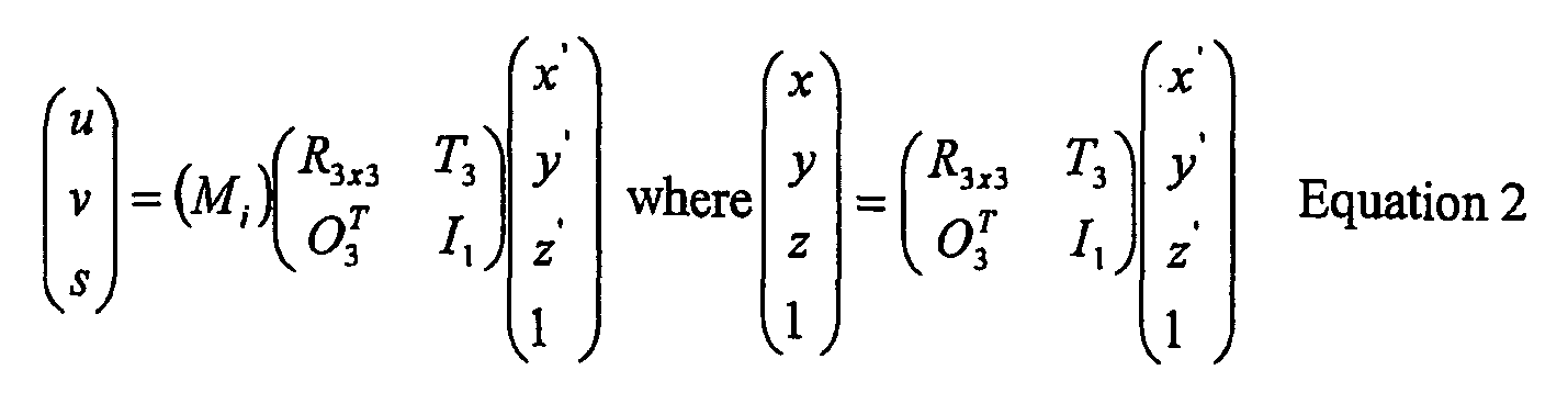
- For example, a preferred orientation can be an orientation in which a particular mammogram is taken.
- Thus, the backprojection for reconstructing tomosynthesis slice images can involve:
- 1.) The selection of the orientation of image slices to be reconstructed. The slice can be either parallel to the "default" reference plane as suggested by
Equation 1, or at another more preferred orientation, which is defined by a 4x4 matrix multiplication operation to the original 3x4 matrix M, as expressed byEquation 2; and - 2.) Selection of the reconstruction voxel grid in space, which can be either a Cartesian grid (
Fig. 5a ) or a Cone beam grid (Fig. 5b ). - It should be clear to those skilled in the relevant technology that the above description is only one example of implementing the new approach and that numerous variations are possible that are within the scope of the description above.
- Thus, in one non-limiting example, this patent specification discloses a method comprising: obtaining tomosynthesis x-ray measurements and at least one 2D x-ray projection mammogram of a patient's breast, wherein the mammogram image and the tomosynthesis measurements are obtained using a cone-shaped or pyramid-shaped imaging x-ray beam, and reconstructing 2D tomosynthesis images from the tomosynthesis measurements, wherein the tomosynthesis images conform to the same geometric coordinate system as the 2D projection mammogram, whereby anatomical structures that appear in the mammogram appear at geometrically corresponding places in respective ones of the tomosynthesis images. The step or steps of reconstructing 2D tomosynthesis images can comprise using a computer-implemented cone beam reconstruction algorithm directly generating the tomosynthesis images. Alternatively, the step or steps of reconstructing the 2D tomosynthesis images can comprise generating information describing initial tomosynthesis images, in which tissue or objects in the breast that are at different heights in the breast but overlap in the mammogram appear at mismatched positions in the initial tomosynthesis images, and using the information describing the initial tomosynthesis images to generate final tomosynthesis images in which said tissue or objects appear at positions that match their positions in the mammogram. This alternative can be implemented by generating the initial tomosynthesis images in an initial coordinate system different from that of the mammogram, and processing the information describing the initial tomosynthesis images into tomosynthewsis images that match the coordinate system of the mammogram. In the initial coordinate system, the initial tomosynthesis images may differ in pixel spacing while the final tomosynthesis images may have the same pixel spacing. The final pixel spacing may be the same as in the mammogram.
- This patent specification also discloses, as another non-limiting example, an x-ray system comprising an x-ray data acquisition unit that uses a cone-shaped or pyramid shaped x-ray beam and an x-ray receptor to obtain tomosynthesis x-ray measurements and x-ray measurements for at least one 2D x-ray projection mammogram of a patient's breast, a pre-processor that receives said measurements from the x-ray receptor and subjects them to pre-processing operations, a tomo/mammo image reconstruction unit that receives the pre-processed images and subjects them to further processing to reconstructing 2D tomosynthesis images and a mammogram, wherein tissue or objects in the breast that are at different heights in the breast but appear superimposed in the mammogram appear at locations in the tomosynthesis images that are the same as or at least match their location in the mammogram, and a display unit that selectively displays one or more of the tomosynthesis images and the mammogram and is under the control of a used interface operated by a health professional. The image reconstruction unit can use a computer-implemented cone beam reconstruction algorithm directly generating the tomosynthesis images. Alternatively, the image reconstruction unit can generate information describing initial tomosynthesis images, in which tissue or objects in the breast that are at different heights in the breast but overlap in the mammogram appear at mismatched positions in the initial tomosynthesis images, and can use the information describing the initial tomosynthesis images to generate final tomosynthesis images in which said objects appear at positions that are the same as or at least match their positions in the mammogram. This alternative can be implemented by generating the initial tomosynthesis images in an initial coordinate system different from that of the mammogram, and processing the information describing the initial tomosynthesis images into tomosynthewsis images that match the coordinate system of the mammogram. In the initial coordinate system, the initial tomosynthesis images may differ in pixel spacing while the final tomosynthesis images may have the same pixel spacing. The final pixel spacing may be the same as in the mammogram.
Claims (18)
- A method comprising:obtaining a plurality of 2D x-ray tomosynthesis projection images of a patient's breast taken at different angles of an imaging x-ray beam (16) relative to the breast (10);using an image reconstruction unit (54) to carry out computer-implemented processing of the tomosynthesis projection images to derive 2D reconstructed tomosynthesis images representative of respective breast slices; anddisplaying on a display unit (56) at least some of the reconstructed tomosynthesis slice images,wherein each reconstructed tomosynthesis image comprises a 2D set of pixel values representing respective voxels of the breast, said pixel values being related to respective pixel positions in the reconstructed tomosynthesis image,characterized in that:said deriving of the reconstructed tomosynthesis images comprises applying a geometry matrix transforming said pixel positions to a coordinate system for the breast in which an object in the breast appears at the same place in each reconstructed tomosynthesis slice image in which the object appears, as in a conventional mammogram of the breast.
- A method as in claim 1 wherein said image reconstruction unit is programmed to carry out a computer-implemented cone beam reconstruction algorithm that directly generates said reconstructed tomosynthesis images from said projection tomosynthesis images.
- A method as in claim 1 wherein said image reconstruction unit is programmed to generate preliminary tomosynthesis images that represent parallel breast slices but in which anatomical structures that are at different heights in the breast but overlap in a conventional mammogram image appear at geometrically mismatched positions, and to use the preliminary tomosynthesis images to generate said reconstructed tomosynthesis images.
- A method as in claim 3 wherein the generating of the preliminary tomosynthesis images comprises conforming the preliminary tomosynthesis images to a preliminary coordinate system different from a coordinate system to which a conventional mammogram image conforms, and processing the preliminary tomosynthesis images into said reconstructed tomosynthesis images
- A method as in claim 4 wherein the preliminary tomosynthesis images differ from each other in pixel spacing while said reconstructed tomosynthesis images are the same in pixel spacing.
- A method as in claim 5 including obtaining a mammogram image comprising values for a 2D set of pixels, wherein the pixel spacing in the reconstructed tomosynthesis images conforms to that of the mammogram image.
- A method as in claim 1 including obtaining a mammogram image comprising values for a 2D set of pixels, wherein the reconstructed tomosynthesis images are characterized by pixel spacing that conforms to that of the mammogram image.
- A method as in claim 1 comprising pre-processing the projection tomosynthesis images to generate filtered information, and backprojecting the filtered information to generate said reconstructed tomosynthesis images, for one of said slices at a time, using a geometry matrix as follows,

where Mi is a 3x4 geometry matrix for a backprojection i, (x,y,z) is a location of an image pixel in one of said reconstructed tomosynthesis images, and (dxdy ) is a location on an x-ray detector element or area for a line that connects a focal spot from which the x-ray emanate and the image pixel. - A method as in claim 8 further comprising applying a 4x4 matrix multiplication operation to said 3x4 geometry matrix Mi according to

to thereby orient said reconstructed tomosynthesis images at selected directions defined by a choice of said 4x4 matrix. - An x-ray system comprising:a data acquisition unit (50) that uses x-rays emanating from an origin (18) and an x-ray receptor (12) to obtain x-ray measurements for a plurality of projection tomosynthesis images of the breast taken at respective angles of an x-ray beam (16) relative to the breast (10);a pre-processor unit (52) configured to receive said x-ray measurements from the x-ray receptor and to subject them to pre-processing computer operations and thereby generate said projection tomosynthesis images;a tomosynthesis image reconstruction unit (54) configured to receive said projection tomosynthesis images and to subject them to computer processing to form reconstructed tomosynthesis images that represent respective slices of the breast; anda display unit that selectively displays one or more of the reconstructed tomosynthesis slice images, said display unit comprising a user interface controlling the display of said imageswhereineach reconstructed tomosynthesis image comprises a 2D set of pixel values representing respective voxels of the breast, said pixel valued being related to respective pixel positions in the reconstructed tomosynthesis image characterized in that:said forming of the reconstructed tomosynthesis images comprises applying a geometry matrix transforming said pixel positions to a coordinate system in which an object in the breast appears at the same place in each reconstructed tomosynthesis slice image in which the object appears, as in the conventional mammogram of the breast.
- A system as in claim 10 wherein said image reconstruction unit comprises a computer-implemented cone beam reconstruction algorithm directly generating the reconstructed tomosynthesis images.
- A system as in claim 10 wherein said image reconstruction unit comprises an algorithm generating preliminary tomosynthesis images that represent breast slices but in which anatomical structures that are at different heights in the breast but overlap in the mammogram image appear at geometrically mismatched positions, and using the preliminary tomosynthesis images to generate said reconstructed tomosynthesis images.
- A system as in claim 12 wherein said reconstruction unit comprises an algorithm conforming the preliminary tomosynthesis images to a preliminary image coordinate system different from a coordinate system to which a conventional mammogram image conforms, and processing the preliminary tomosynthesis images into said reconstructed tomosynthesis images
- A system as in claim 13 wherein said reconstruction unit forms the preliminary tomosynthesis images at pixel spacing that differ from each other and forms said reconstructed tomosynthesis images in pixel spacing that are the same for a plurality of the reconstructed tomosynthesis images.
- A system as in claim 14 including generating a mammogram image, wherein said reconstruction unit forms the reconstructed tomosynthesis images at a pixel spacing that conforms to that of the mammogram image.
- A system as in claim 10 including generating a mammogram image, wherein said reconstruction unit forms the reconstructed tomosynthesis images at a pixel spacing that conforms to that of the mammogram image.
- A system as in claim 10 in which said reconstruction unit comprises and algorithm filtering the projection tomosynthesis images to generate filtered images, and backprojecting the filtered images to generate said reconstructed tomosynthesis images, for one of said slices at a time, using a geometry matrix as follows,

where Mi is a 3x4 geometry matrix for a backprojection i, (x,y,z) is a location of an image pixel in one of said reconstructed tomosynthesis images, and (dx,dy ) is a location on an x-ray detector element or area for a line that connects a focal spot from which the x-ray emanate and the image pixel. - A system as in claim 17 wherein said algorithm further comprises applying a 4x4 matrix multiplication operation to said 3x4 geometry matrix Mi according to

to thereby orient said reconstructed tomosynthesis images at selected directions defined by a choice of said 4x4 matrix.
Priority Applications (1)
| Application Number | Priority Date | Filing Date | Title |
|---|---|---|---|
| EP13157683.7A EP2602743B1 (en) | 2004-11-15 | 2005-11-15 | Matching geometry generation and display of mammograms and tomosynthesis images |
Applications Claiming Priority (2)
| Application Number | Priority Date | Filing Date | Title |
|---|---|---|---|
| US62851604P | 2004-11-15 | 2004-11-15 | |
| PCT/US2005/041941 WO2006055830A2 (en) | 2004-11-15 | 2005-11-15 | Matching geometry generation and display of mammograms and tomosynthesis images |
Related Child Applications (1)
| Application Number | Title | Priority Date | Filing Date |
|---|---|---|---|
| EP13157683.7A Division EP2602743B1 (en) | 2004-11-15 | 2005-11-15 | Matching geometry generation and display of mammograms and tomosynthesis images |
Publications (3)
| Publication Number | Publication Date |
|---|---|
| EP1815388A2 EP1815388A2 (en) | 2007-08-08 |
| EP1815388A4 EP1815388A4 (en) | 2011-06-08 |
| EP1815388B1 true EP1815388B1 (en) | 2013-03-06 |
Family
ID=36407794
Family Applications (2)
| Application Number | Title | Priority Date | Filing Date |
|---|---|---|---|
| EP05824734A Expired - Lifetime EP1815388B1 (en) | 2004-11-15 | 2005-11-15 | Matching geometry generation and display of mammograms and tomosynthesis images |
| EP13157683.7A Expired - Lifetime EP2602743B1 (en) | 2004-11-15 | 2005-11-15 | Matching geometry generation and display of mammograms and tomosynthesis images |
Family Applications After (1)
| Application Number | Title | Priority Date | Filing Date |
|---|---|---|---|
| EP13157683.7A Expired - Lifetime EP2602743B1 (en) | 2004-11-15 | 2005-11-15 | Matching geometry generation and display of mammograms and tomosynthesis images |
Country Status (3)
| Country | Link |
|---|---|
| US (7) | US7702142B2 (en) |
| EP (2) | EP1815388B1 (en) |
| WO (1) | WO2006055830A2 (en) |
Families Citing this family (133)
| Publication number | Priority date | Publication date | Assignee | Title |
|---|---|---|---|---|
| US7760924B2 (en) * | 2002-11-27 | 2010-07-20 | Hologic, Inc. | System and method for generating a 2D image from a tomosynthesis data set |
| US10638994B2 (en) | 2002-11-27 | 2020-05-05 | Hologic, Inc. | X-ray mammography with tomosynthesis |
| US8565372B2 (en) | 2003-11-26 | 2013-10-22 | Hologic, Inc | System and method for low dose tomosynthesis |
| US8571289B2 (en) | 2002-11-27 | 2013-10-29 | Hologic, Inc. | System and method for generating a 2D image from a tomosynthesis data set |
| US7123684B2 (en) | 2002-11-27 | 2006-10-17 | Hologic, Inc. | Full field mammography with tissue exposure control, tomosynthesis, and dynamic field of view processing |
| US7577282B2 (en) | 2002-11-27 | 2009-08-18 | Hologic, Inc. | Image handling and display in X-ray mammography and tomosynthesis |
| US7616801B2 (en) | 2002-11-27 | 2009-11-10 | Hologic, Inc. | Image handling and display in x-ray mammography and tomosynthesis |
| US7662082B2 (en) | 2004-11-05 | 2010-02-16 | Theragenics Corporation | Expandable brachytherapy device |
| EP1815388B1 (en) | 2004-11-15 | 2013-03-06 | Hologic, Inc. | Matching geometry generation and display of mammograms and tomosynthesis images |
| US7869563B2 (en) | 2004-11-26 | 2011-01-11 | Hologic, Inc. | Integrated multi-mode mammography/tomosynthesis x-ray system and method |
| US10008184B2 (en) | 2005-11-10 | 2018-06-26 | Hologic, Inc. | System and method for generating a 2D image using mammography and/or tomosynthesis image data |
| US7465268B2 (en) | 2005-11-18 | 2008-12-16 | Senorx, Inc. | Methods for asymmetrical irradiation of a body cavity |
| WO2007095330A2 (en) | 2006-02-15 | 2007-08-23 | Hologic Inc | Breast biopsy and needle localization using tomosynthesis systems |
| SE0702061L (en) * | 2007-09-17 | 2009-03-18 | Xcounter Ab | Method for creating, displaying and analyzing X-rays and device for implementing the method |
| US7630533B2 (en) | 2007-09-20 | 2009-12-08 | Hologic, Inc. | Breast tomosynthesis with display of highlighted suspected calcifications |
| US7929743B2 (en) * | 2007-10-02 | 2011-04-19 | Hologic, Inc. | Displaying breast tomosynthesis computer-aided detection results |
| US7792245B2 (en) | 2008-06-24 | 2010-09-07 | Hologic, Inc. | Breast tomosynthesis system with shifting face shield |
| US7991106B2 (en) | 2008-08-29 | 2011-08-02 | Hologic, Inc. | Multi-mode tomosynthesis/mammography gain calibration and image correction using gain map information from selected projection angles |
| JP2010068929A (en) * | 2008-09-17 | 2010-04-02 | Fujifilm Corp | Mamma x-ray transmission plane image and tomographic image radiographing apparatus |
| JP2010104771A (en) * | 2008-09-30 | 2010-05-13 | Fujifilm Corp | Radiation image diagnosing system |
| US8515005B2 (en) | 2009-11-23 | 2013-08-20 | Hologic Inc. | Tomosynthesis with shifting focal spot and oscillating collimator blades |
| WO2010060007A1 (en) * | 2008-11-24 | 2010-05-27 | Hologic Inc. | Method and system for controlling x-ray focal spot characteristics for tomosynthesis and mammography imaging |
| SE533704C2 (en) | 2008-12-05 | 2010-12-07 | Flatfrog Lab Ab | Touch sensitive apparatus and method for operating the same |
| US9579524B2 (en) | 2009-02-11 | 2017-02-28 | Hologic, Inc. | Flexible multi-lumen brachytherapy device |
| US9248311B2 (en) | 2009-02-11 | 2016-02-02 | Hologic, Inc. | System and method for modifying a flexibility of a brachythereapy catheter |
| US10207126B2 (en) | 2009-05-11 | 2019-02-19 | Cytyc Corporation | Lumen visualization and identification system for multi-lumen balloon catheter |
| EP2485651B1 (en) | 2009-10-08 | 2020-12-23 | Hologic, Inc. | Needle breast biopsy system |
| FR2954556B1 (en) * | 2009-12-22 | 2017-07-28 | Gen Electric | METHOD OF PROCESSING TOMOSYNTHESIS ACQUISITIONS TO OBTAIN REPRESENTATION OF THE CONTENT OF AN ORGAN |
| KR101689866B1 (en) | 2010-07-29 | 2016-12-27 | 삼성전자주식회사 | Method and apparatus of processing image and medical image system employing the same |
| US9352172B2 (en) | 2010-09-30 | 2016-05-31 | Hologic, Inc. | Using a guide member to facilitate brachytherapy device swap |
| CN105769236B (en) * | 2010-10-05 | 2020-02-07 | 霍洛吉克公司 | Upright X-ray chest imaging system and method |
| WO2012050510A1 (en) * | 2010-10-11 | 2012-04-19 | Flatfrog Laboratories Ab | Touch determination by tomographic reconstruction |
| US9075903B2 (en) | 2010-11-26 | 2015-07-07 | Hologic, Inc. | User interface for medical image review workstation |
| EP2651308B1 (en) | 2010-12-14 | 2020-03-11 | Hologic, Inc. | System and method for fusing three dimensional image data from a plurality of different imaging systems for use in diagnostic imaging |
| US10342992B2 (en) | 2011-01-06 | 2019-07-09 | Hologic, Inc. | Orienting a brachytherapy applicator |
| DE102011003137A1 (en) * | 2011-01-25 | 2012-07-26 | Siemens Aktiengesellschaft | Imaging method with an improved representation of a tissue area |
| WO2012106204A1 (en) | 2011-01-31 | 2012-08-09 | University Of Massachusetts | Tomosynthesis imaging |
| EP2684157B1 (en) | 2011-03-08 | 2017-12-13 | Hologic Inc. | System and method for dual energy and/or contrast enhanced breast imaging for screening, diagnosis and biopsy |
| US11259759B2 (en) | 2011-11-18 | 2022-03-01 | Hologic Inc. | X-ray mammography and/or breast tomosynthesis using a compression paddle |
| US9332947B2 (en) | 2011-11-18 | 2016-05-10 | Hologic, Inc. | X-ray mammography and/or breast tomosynthesis using a compression paddle with an inflatable jacket with dual bottom layer joined at a seam enhancing imaging and improving patient comfort |
| US9782135B2 (en) | 2011-11-18 | 2017-10-10 | Hologic, Inc. | X-ray mammography and/or breast tomosynthesis using a compression paddle |
| EP2782505B1 (en) | 2011-11-27 | 2020-04-22 | Hologic, Inc. | System and method for generating a 2d image using mammography and/or tomosynthesis image data |
| EP3315072B1 (en) | 2012-02-13 | 2020-04-29 | Hologic, Inc. | System and method for navigating a tomosynthesis stack using synthesized image data |
| EP2830346A4 (en) * | 2012-03-19 | 2015-12-02 | Kyocera Corp | MOBILE COMMUNICATION SYSTEM AND MOBILE COMMUNICATION METHOD |
| US10168835B2 (en) | 2012-05-23 | 2019-01-01 | Flatfrog Laboratories Ab | Spatial resolution in touch displays |
| US9076246B2 (en) * | 2012-08-09 | 2015-07-07 | Hologic, Inc. | System and method of overlaying images of different modalities |
| US9517038B2 (en) * | 2012-10-12 | 2016-12-13 | University Of Virginia Patent Foundation | Apparatus and method for breast immobilization |
| FR2997284B1 (en) | 2012-10-30 | 2016-06-17 | Gen Electric | METHOD FOR OBTAINING TOMOSYNTHESIS IMAGES |
| US8983156B2 (en) | 2012-11-23 | 2015-03-17 | Icad, Inc. | System and method for improving workflow efficiences in reading tomosynthesis medical image data |
| WO2014110283A1 (en) | 2013-01-10 | 2014-07-17 | Hologic, Inc. | System and method for reducing data transmission volume in tomosynthesis |
| WO2014150274A1 (en) | 2013-03-15 | 2014-09-25 | Hologic, Inc. | System and method for reviewing and analyzing cytological specimens |
| EP2967473B1 (en) | 2013-03-15 | 2020-02-19 | Hologic, Inc. | System and method for navigating a tomosynthesis stack including automatic focusing |
| EP2967479B1 (en) | 2013-03-15 | 2018-01-31 | Hologic Inc. | Tomosynthesis-guided biopsy in prone |
| WO2014168567A1 (en) | 2013-04-11 | 2014-10-16 | Flatfrog Laboratories Ab | Tomographic processing for touch detection |
| EP3014577A1 (en) | 2013-06-28 | 2016-05-04 | Koninklijke Philips N.V. | Methods for generation of edge-preserving synthetic mammograms from tomosynthesis data |
| WO2015005847A1 (en) | 2013-07-12 | 2015-01-15 | Flatfrog Laboratories Ab | Partial detect mode |
| JP6523265B2 (en) | 2013-10-09 | 2019-05-29 | ホロジック, インコーポレイテッドHologic, Inc. | X-ray chest tomosynthesis to improve spatial resolution including flattened chest thickness direction |
| KR102340594B1 (en) | 2013-10-24 | 2021-12-20 | 앤드류 피 스미스 | System and method for navigating x-ray guided breast biopsy |
| CN105705096B (en) | 2013-10-30 | 2020-11-03 | 皇家飞利浦有限公司 | Method and apparatus for displaying medical images |
| US10126882B2 (en) | 2014-01-16 | 2018-11-13 | Flatfrog Laboratories Ab | TIR-based optical touch systems of projection-type |
| WO2015108479A1 (en) | 2014-01-16 | 2015-07-23 | Flatfrog Laboratories Ab | Light coupling in tir-based optical touch systems |
| US9613440B2 (en) * | 2014-02-12 | 2017-04-04 | General Electric Company | Digital breast Tomosynthesis reconstruction using adaptive voxel grid |
| WO2015130916A1 (en) | 2014-02-28 | 2015-09-03 | Hologic, Inc. | System and method for generating and displaying tomosynthesis image slabs |
| WO2015199602A1 (en) | 2014-06-27 | 2015-12-30 | Flatfrog Laboratories Ab | Detection of surface contamination |
| JP6126058B2 (en) * | 2014-09-30 | 2017-05-10 | 富士フイルム株式会社 | Image display apparatus, image processing apparatus, radiographic imaging system, tomographic image display method, and tomographic image display program. |
| WO2016122385A1 (en) | 2015-01-28 | 2016-08-04 | Flatfrog Laboratories Ab | Dynamic touch quarantine frames |
| US10318074B2 (en) | 2015-01-30 | 2019-06-11 | Flatfrog Laboratories Ab | Touch-sensing OLED display with tilted emitters |
| EP3537269A1 (en) | 2015-02-09 | 2019-09-11 | FlatFrog Laboratories AB | Optical touch system |
| WO2016140612A1 (en) | 2015-03-02 | 2016-09-09 | Flatfrog Laboratories Ab | Optical component for light coupling |
| US10692213B2 (en) | 2015-03-10 | 2020-06-23 | Koninklijke Philips N.V. | Retrieval of corresponding structures in pairs of medical images |
| US9984478B2 (en) * | 2015-07-28 | 2018-05-29 | PME IP Pty Ltd | Apparatus and method for visualizing digital breast tomosynthesis and other volumetric images |
| KR102400705B1 (en) | 2015-12-09 | 2022-05-23 | 플라트프로그 라보라토리즈 에이비 | Improved stylus identification |
| JP7085492B2 (en) | 2016-04-22 | 2022-06-16 | ホロジック,インコーポレイテッド | Tomosynthesis with a shift focus X-ray system using an addressable array |
| EP3465539B1 (en) | 2016-05-27 | 2024-04-17 | Hologic, Inc. | Synchronized surface and internal tumor detection |
| DE102016217776A1 (en) * | 2016-09-16 | 2018-03-22 | Siemens Healthcare Gmbh | Simultaneous imaging of functional and morphological X-ray image data of a breast |
| WO2018081569A1 (en) * | 2016-10-27 | 2018-05-03 | Artemiadis Panagiotis | Systems and methods for a hybrid brain interface for robotic swarms using eeg signals and an input device |
| JP2019533510A (en) | 2016-11-08 | 2019-11-21 | ホロジック, インコーポレイテッドHologic, Inc. | Imaging using curved compression elements |
| US10096106B2 (en) * | 2016-11-10 | 2018-10-09 | General Electric Company | Combined medical imaging |
| CN110100226A (en) | 2016-11-24 | 2019-08-06 | 平蛙实验室股份公司 | The Automatic Optimal of touch signal |
| JP7232759B2 (en) * | 2016-11-25 | 2023-03-03 | ホロジック, インコーポレイテッド | Healthcare information manipulation and visualization controller |
| CN119847372A (en) | 2016-12-07 | 2025-04-18 | 平蛙实验室股份公司 | Touch sensing device |
| CN116679845A (en) | 2017-02-06 | 2023-09-01 | 平蛙实验室股份公司 | touch sensing device |
| US20180275830A1 (en) | 2017-03-22 | 2018-09-27 | Flatfrog Laboratories Ab | Object characterisation for touch displays |
| WO2018182476A1 (en) | 2017-03-28 | 2018-10-04 | Flatfrog Laboratories Ab | Touch sensing apparatus and method for assembly |
| EP3600052A1 (en) | 2017-03-30 | 2020-02-05 | Hologic, Inc. | System and method for targeted object enhancement to generate synthetic breast tissue images |
| WO2018183549A1 (en) | 2017-03-30 | 2018-10-04 | Hologic, Inc. | System and method for synthesizing low-dimensional image data from high-dimensional image data using an object grid enhancement |
| CN110621231B (en) * | 2017-03-30 | 2024-02-23 | 豪洛捷公司 | Systems and methods for hierarchical multi-level feature image synthesis and representation |
| JP7039179B2 (en) | 2017-04-13 | 2022-03-22 | キヤノン株式会社 | Information processing equipment, information processing system, information processing method and program |
| JP6949535B2 (en) * | 2017-04-13 | 2021-10-13 | キヤノン株式会社 | Information processing equipment, information processing system, information processing method and program |
| US11403483B2 (en) | 2017-06-20 | 2022-08-02 | Hologic, Inc. | Dynamic self-learning medical image method and system |
| JP7229228B2 (en) | 2017-08-11 | 2023-02-27 | ホロジック, インコーポレイテッド | Breast compression paddle with access angle |
| EP4129188A1 (en) | 2017-08-16 | 2023-02-08 | Hologic, Inc. | Techniques for breast imaging patient motion artifact compensation |
| EP3449835B1 (en) | 2017-08-22 | 2023-01-11 | Hologic, Inc. | Computed tomography system and method for imaging multiple anatomical targets |
| CN117311543A (en) | 2017-09-01 | 2023-12-29 | 平蛙实验室股份公司 | Touch sensing device |
| WO2019172826A1 (en) | 2018-03-05 | 2019-09-12 | Flatfrog Laboratories Ab | Improved touch-sensing apparatus |
| WO2019213532A1 (en) | 2018-05-04 | 2019-11-07 | Hologic, Inc. | Biopsy needle visualization |
| US12121304B2 (en) | 2018-05-04 | 2024-10-22 | Hologic, Inc. | Introducer and localization wire visualization |
| CN108852392A (en) * | 2018-05-21 | 2018-11-23 | 苏州达影医疗设备有限公司 | Cone-shaped beam image reconstruction method, image system and camera chain |
| US11090017B2 (en) | 2018-09-13 | 2021-08-17 | Hologic, Inc. | Generating synthesized projection images for 3D breast tomosynthesis or multi-mode x-ray breast imaging |
| WO2020068851A1 (en) | 2018-09-24 | 2020-04-02 | Hologic, Inc. | Breast mapping and abnormality localization |
| JP7482860B2 (en) | 2018-09-28 | 2024-05-14 | ホロジック, インコーポレイテッド | System and method for generating synthetic breast tissue images with high density element suppression - Patents.com |
| CN112889016A (en) | 2018-10-20 | 2021-06-01 | 平蛙实验室股份公司 | Frame for touch sensitive device and tool therefor |
| DE202019006040U1 (en) | 2018-11-25 | 2024-08-06 | Hologic Inc. | Multimodality suspension protocols |
| WO2020153890A1 (en) | 2019-01-25 | 2020-07-30 | Flatfrog Laboratories Ab | A videoconferencing terminal and method of operating the same |
| EP3948884A1 (en) | 2019-03-29 | 2022-02-09 | Hologic, Inc. | Snip-triggered digital image report generation |
| US11883206B2 (en) | 2019-07-29 | 2024-01-30 | Hologic, Inc. | Personalized breast imaging system |
| DE202020006045U1 (en) | 2019-09-27 | 2024-07-02 | Hologic Inc. | AI system to predict reading time and reading complexity for reviewing 2D/3D breast images |
| WO2021081483A1 (en) | 2019-10-25 | 2021-04-29 | DeepHealth, Inc. | System and method for analyzing three-dimensional image data |
| EP4066089B1 (en) | 2019-11-25 | 2024-09-25 | FlatFrog Laboratories AB | A touch-sensing apparatus |
| EP3832689A3 (en) | 2019-12-05 | 2021-08-11 | Hologic, Inc. | Systems and methods for improved x-ray tube life |
| EP4081952A4 (en) | 2019-12-23 | 2024-01-24 | Deephealth, Inc. | Systems and methods for analyzing two-dimensional and three-dimensional image data |
| KR20220130759A (en) | 2020-01-24 | 2022-09-27 | 홀로직, 인크. | Horizontal-Displaceable Foam Breast Compression Paddles |
| EP4101386A4 (en) | 2020-02-04 | 2023-07-12 | FUJIFILM Corporation | IMAGE ADJUSTMENT DEVICE, METHOD AND PROGRAM |
| US12282653B2 (en) | 2020-02-08 | 2025-04-22 | Flatfrog Laboratories Ab | Touch apparatus with low latency interactions |
| US11893189B2 (en) | 2020-02-10 | 2024-02-06 | Flatfrog Laboratories Ab | Touch-sensing apparatus |
| EP4119055B1 (en) | 2020-03-13 | 2024-10-30 | FUJIFILM Corporation | Image generation device and program, learning device and program, and image processing device and program |
| JP7446410B2 (en) | 2020-03-18 | 2024-03-08 | 富士フイルム株式会社 | Image processing device, method and program |
| WO2021186956A1 (en) | 2020-03-18 | 2021-09-23 | 富士フイルム株式会社 | Image processing device, method, and program |
| KR102848014B1 (en) | 2020-03-27 | 2025-08-21 | 홀로직, 인크. | Systems and methods for identifying regions of interest in multiple imaging modalities |
| US11471118B2 (en) | 2020-03-27 | 2022-10-18 | Hologic, Inc. | System and method for tracking x-ray tube focal spot position |
| JP2023519878A (en) | 2020-03-27 | 2023-05-15 | ホロジック, インコーポレイテッド | Systems and methods for correlating regions of interest in multiple imaging modalities |
| US11481038B2 (en) | 2020-03-27 | 2022-10-25 | Hologic, Inc. | Gesture recognition in controlling medical hardware or software |
| DE102021210289A1 (en) * | 2020-09-30 | 2022-03-31 | Siemens Healthcare Gmbh | Method for generating result layer images with at least partially different layer thicknesses |
| US20220164951A1 (en) | 2020-11-20 | 2022-05-26 | Hologic, Inc. | Systems and methods for using ai to identify regions of interest in medical images |
| EP4329627A1 (en) | 2021-04-26 | 2024-03-06 | Hologic, Inc. | Systems and methods for measuring thickness of foam compressive elements |
| US11786191B2 (en) | 2021-05-17 | 2023-10-17 | Hologic, Inc. | Contrast-enhanced tomosynthesis with a copper filter |
| US12288275B2 (en) * | 2021-07-28 | 2025-04-29 | GE Precision Healthcare LLC | Methods and systems for breast tomosynthesis |
| US12186119B2 (en) | 2021-10-05 | 2025-01-07 | Hologic, Inc. | Interactive model interface for image selection in medical imaging systems |
| US12254586B2 (en) | 2021-10-25 | 2025-03-18 | Hologic, Inc. | Auto-focus tool for multimodality image review |
| EP4441710A1 (en) | 2021-11-29 | 2024-10-09 | Hologic, Inc. | Systems and methods for correlating objects of interest |
| US12414217B2 (en) | 2022-02-07 | 2025-09-09 | Hologic, Inc. | Systems and methods for adaptively controlling filament current in an X-ray tube |
| DE102023205095A1 (en) * | 2023-05-31 | 2024-12-05 | Siemens Healthineers Ag | Combination of a 2D X-ray image with a tomosynthesis image |
| WO2025212901A1 (en) | 2024-04-03 | 2025-10-09 | Hologic, Inc. | Reducing tomosynthesis file sizes |
Family Cites Families (140)
| Publication number | Priority date | Publication date | Assignee | Title |
|---|---|---|---|---|
| JP4054402B2 (en) | 1997-04-25 | 2008-02-27 | 株式会社東芝 | X-ray tomography equipment |
| US3502878A (en) | 1967-09-22 | 1970-03-24 | Us Health Education & Welfare | Automatic x-ray apparatus for limiting the field size of a projected x-ray beam in response to film size and to source-to-film distance |
| US3863073A (en) | 1973-04-26 | 1975-01-28 | Machlett Lab Inc | Automatic system for precise collimation of radiation |
| US3971950A (en) | 1975-04-14 | 1976-07-27 | Xerox Corporation | Independent compression and positioning device for use in mammography |
| US4160906A (en) | 1977-06-23 | 1979-07-10 | General Electric Company | Anatomically coordinated user dominated programmer for diagnostic x-ray apparatus |
| DE2838901C2 (en) | 1978-09-06 | 1986-11-06 | Siemens AG, 1000 Berlin und 8000 München | Catapult drawer |
| FR2512024A1 (en) | 1981-08-27 | 1983-03-04 | Adir | TRICYCLIC ETHERS, PREPARATION THEREOF AND PHARMACEUTICAL COMPOSITIONS CONTAINING THEM |
| FR2549248B1 (en) | 1983-06-24 | 1986-01-31 | Thomson Csf | RETRACTABLE CASSETTE HOLDER FOR RADIOLOGICAL AND RADIOGRAPHIC EXAMINATION APPARATUS |
| DE3339775A1 (en) | 1983-11-03 | 1985-05-15 | Siemens AG, 1000 Berlin und 8000 München | X-RAY DIAGNOSTIC DEVICE WITH RADIATION FILTERS |
| JPS60129034A (en) | 1983-12-16 | 1985-07-10 | 横河メディカルシステム株式会社 | Operation table of x-ray tomographic apparatus |
| US4706269A (en) | 1985-03-11 | 1987-11-10 | Reina Leo J | Anti-scatter grid structure |
| US4773087A (en) | 1986-04-14 | 1988-09-20 | University Of Rochester | Quality of shadowgraphic x-ray images |
| USRE33634E (en) | 1986-09-23 | 1991-07-09 | Method and structure for optimizing radiographic quality by controlling X-ray tube voltage, current focal spot size and exposure time | |
| US4821727A (en) | 1986-10-30 | 1989-04-18 | Elscint Ltd. | Mammographic biopsy needle holder system |
| US4819258A (en) | 1986-11-28 | 1989-04-04 | Bennett X-Ray Corp. | Auto-setting of KV in an x-ray machine after selection of technic factors |
| US5051904A (en) | 1988-03-24 | 1991-09-24 | Olganix Corporation | Computerized dynamic tomography system |
| DK654488A (en) | 1988-11-23 | 1990-05-24 | Nordisk Roentgen Tech App | ROENTGENAPPARAT |
| FR2645006A1 (en) | 1989-03-29 | 1990-10-05 | Gen Electric Cgr | MAMMOGRAPH HAVING INTEGRATED STEREOTAXIC VIEWING DEVICE AND METHOD OF USING SUCH A MAMMOGRAPHER |
| FR2646340A1 (en) | 1989-04-28 | 1990-11-02 | Gen Electric Cgr | ADJUSTABLE CASSETTE HOLDER IN DIMENSION AND POSITION FOR MAMMOGRAPHY |
| DE58908415D1 (en) | 1989-07-03 | 1994-10-27 | Siemens Ag | X-ray diagnostic device for mammography images. |
| US4969174A (en) | 1989-09-06 | 1990-11-06 | General Electric Company | Scanning mammography system with reduced scatter radiation |
| CA2014918A1 (en) | 1989-09-06 | 1991-03-06 | James A. Mcfaul | Scanning mammography system with improved skin line viewing |
| US5240011A (en) | 1991-11-27 | 1993-08-31 | Fischer Imaging Corporation | Motorized biopsy needle positioner |
| US5415169A (en) | 1989-11-21 | 1995-05-16 | Fischer Imaging Corporation | Motorized mammographic biopsy apparatus |
| US5078142A (en) | 1989-11-21 | 1992-01-07 | Fischer Imaging Corporation | Precision mammographic needle biopsy system |
| US5199056A (en) | 1989-11-28 | 1993-03-30 | Darrah Carol J | Mammography compression paddle |
| US5481623A (en) | 1990-04-19 | 1996-01-02 | Fuji Photo Film Co., Ltd. | Apparatus for determining an image position on imaging media |
| US5163075A (en) | 1991-08-08 | 1992-11-10 | Eastman Kodak Company | Contrast enhancement of electrographic imaging |
| US5594769A (en) | 1991-11-27 | 1997-01-14 | Thermotrex Corporation | Method and apparatus for obtaining stereotactic mammographic guided needle breast biopsies |
| US5289520A (en) | 1991-11-27 | 1994-02-22 | Lorad Corporation | Stereotactic mammography imaging system with prone position examination table and CCD camera |
| US5359637A (en) * | 1992-04-28 | 1994-10-25 | Wake Forest University | Self-calibrated tomosynthetic, radiographic-imaging system, method, and device |
| US5596200A (en) | 1992-10-14 | 1997-01-21 | Primex | Low dose mammography system |
| FR2703237B1 (en) | 1993-03-29 | 1995-05-19 | Ge Medical Syst Sa | Mammograph equipped with a stereotaxic camera with digital detector and method of using such a mammograph. |
| US5365562A (en) | 1993-09-20 | 1994-11-15 | Fischer Imaging Corporation | Digital imaging apparatus |
| US6075879A (en) | 1993-09-29 | 2000-06-13 | R2 Technology, Inc. | Method and system for computer-aided lesion detection using information from multiple images |
| US5526394A (en) | 1993-11-26 | 1996-06-11 | Fischer Imaging Corporation | Digital scan mammography apparatus |
| US5452367A (en) | 1993-11-29 | 1995-09-19 | Arch Development Corporation | Automated method and system for the segmentation of medical images |
| CA2113752C (en) | 1994-01-19 | 1999-03-02 | Stephen Michael Rooks | Inspection system for cross-sectional imaging |
| DE4414689C2 (en) | 1994-04-26 | 1996-08-29 | Siemens Ag | X-ray diagnostic device |
| US5553111A (en) | 1994-10-26 | 1996-09-03 | The General Hospital Corporation | Apparatus and method for improved tissue imaging |
| US5506877A (en) | 1994-11-23 | 1996-04-09 | The General Hospital Corporation | Mammography breast compression device and method |
| US5657362A (en) | 1995-02-24 | 1997-08-12 | Arch Development Corporation | Automated method and system for computerized detection of masses and parenchymal distortions in medical images |
| US6216540B1 (en) | 1995-06-06 | 2001-04-17 | Robert S. Nelson | High resolution device and method for imaging concealed objects within an obscuring medium |
| US5818898A (en) | 1995-11-07 | 1998-10-06 | Kabushiki Kaisha Toshiba | X-ray imaging apparatus using X-ray planar detector |
| US5627869A (en) | 1995-11-22 | 1997-05-06 | Thermotrex Corporation | Mammography apparatus with proportional collimation |
| FI955636A0 (en) | 1995-11-23 | 1995-11-23 | Planmed Oy | Foerfarande och system Foer styrning av funktionerna av en mammografiaanordning |
| US5769086A (en) | 1995-12-06 | 1998-06-23 | Biopsys Medical, Inc. | Control system and method for automated biopsy device |
| DE19619915A1 (en) | 1996-05-17 | 1997-11-20 | Siemens Ag | Process for creating tomosynthesis images |
| DE19619913C2 (en) | 1996-05-17 | 2001-03-15 | Sirona Dental Systems Gmbh | X-ray diagnostic device for tomosynthesis |
| DE19619924A1 (en) | 1996-05-17 | 1997-11-20 | Siemens Ag | Tomosynthetic image generating method |
| DE19619925C2 (en) | 1996-05-17 | 1999-09-09 | Sirona Dental Systems Gmbh | X-ray diagnostic device for tomosynthesis |
| DE69739995D1 (en) * | 1996-07-23 | 2010-10-28 | Gen Hospital Corp | ARRANGEMENT TO MAMMOGRAPHY BY TOMOSYNTHESIS |
| US5986662A (en) * | 1996-10-16 | 1999-11-16 | Vital Images, Inc. | Advanced diagnostic viewer employing automated protocol selection for volume-rendered imaging |
| US6137527A (en) | 1996-12-23 | 2000-10-24 | General Electric Company | System and method for prompt-radiology image screening service via satellite |
| US5999639A (en) | 1997-09-04 | 1999-12-07 | Qualia Computing, Inc. | Method and system for automated detection of clustered microcalcifications from digital mammograms |
| US6442288B1 (en) | 1997-12-17 | 2002-08-27 | Siemens Aktiengesellschaft | Method for reconstructing a three-dimensional image of an object scanned in the context of a tomosynthesis, and apparatus for tomosynthesis |
| JP3554172B2 (en) | 1998-01-09 | 2004-08-18 | キヤノン株式会社 | Radiography equipment |
| US6175117B1 (en) | 1998-01-23 | 2001-01-16 | Quanta Vision, Inc. | Tissue analysis apparatus |
| US6289235B1 (en) | 1998-03-05 | 2001-09-11 | Wake Forest University | Method and system for creating three-dimensional images using tomosynthetic computed tomography |
| US6081577A (en) * | 1998-07-24 | 2000-06-27 | Wake Forest University | Method and system for creating task-dependent three-dimensional images |
| US6375352B1 (en) | 1999-10-01 | 2002-04-23 | General Electric Company | Apparatus and method for obtaining x-ray tomosynthesis data for mammography |
| US6141398A (en) * | 1998-08-25 | 2000-10-31 | General Electric Company | Protocol driven image reconstruction, display, and processing in a multislice imaging system |
| EP1143845A4 (en) | 1998-11-25 | 2004-10-06 | Fischer Imaging Corp | USER INTERFACE SYSTEM FOR MAMMOGRAPHIC IMAGER |
| FR2786388B1 (en) | 1998-11-27 | 2001-02-16 | Ge Medical Syst Sa | METHOD FOR DETECTING FABRIC OF A SPECIFIC NATURE IN DIGITAL RADIOLOGY AND ITS USE FOR ADJUSTING THE EXPOSURE PARAMETERS |
| US6149301A (en) | 1998-12-30 | 2000-11-21 | General Electric Company | X-ray target centering apparatus for radiographic imaging system |
| US6233473B1 (en) | 1999-02-16 | 2001-05-15 | Hologic, Inc. | Determining body composition using fan beam dual-energy x-ray absorptiometry |
| US6272207B1 (en) | 1999-02-18 | 2001-08-07 | Creatv Microtech, Inc. | Method and apparatus for obtaining high-resolution digital X-ray and gamma ray images |
| US6256370B1 (en) | 2000-01-24 | 2001-07-03 | General Electric Company | Method and apparatus for performing tomosynthesis |
| US6689142B1 (en) | 1999-04-26 | 2004-02-10 | Scimed Life Systems, Inc. | Apparatus and methods for guiding a needle |
| US6292530B1 (en) | 1999-04-29 | 2001-09-18 | General Electric Company | Method and apparatus for reconstructing image data acquired by a tomosynthesis x-ray imaging system |
| DE19922346C2 (en) | 1999-05-14 | 2003-06-18 | Siemens Ag | X-ray diagnostic device for tomosynthesis or layering |
| US6243441B1 (en) | 1999-07-13 | 2001-06-05 | Edge Medical Devices | Active matrix detector for X-ray imaging |
| US6633674B1 (en) * | 1999-11-24 | 2003-10-14 | General Electric Company | Picture archiving and communication system employing improved data compression |
| US6645520B2 (en) | 1999-12-16 | 2003-11-11 | Dermatrends, Inc. | Transdermal administration of nonsteroidal anti-inflammatory drugs using hydroxide-releasing agents as permeation enhancers |
| FR2803069B1 (en) | 1999-12-28 | 2002-12-13 | Ge Medical Syst Sa | METHOD AND SYSTEM FOR COMPENSATING THE THICKNESS OF AN ORGAN |
| US6411836B1 (en) * | 1999-12-30 | 2002-06-25 | General Electric Company | Method and apparatus for user preferences configuring in an image handling system |
| US6744848B2 (en) | 2000-02-11 | 2004-06-01 | Brandeis University | Method and system for low-dose three-dimensional imaging of a scene |
| GB0006598D0 (en) * | 2000-03-17 | 2000-05-10 | Isis Innovation | Three-dimensional reconstructions from images |
| US6327336B1 (en) | 2000-06-05 | 2001-12-04 | Direct Radiography Corp. | Radiogram showing location of automatic exposure control sensor |
| JP2002052018A (en) * | 2000-08-11 | 2002-02-19 | Canon Inc | Image display device, image display method, and storage medium |
| EP1267722A1 (en) | 2000-10-20 | 2003-01-02 | Koninklijke Philips Electronics N.V. | Tomosynthesis in a limited angular range |
| US6758824B1 (en) | 2000-11-06 | 2004-07-06 | Suros Surgical Systems, Inc. | Biopsy apparatus |
| WO2002069808A2 (en) | 2000-11-06 | 2002-09-12 | Suros Surgical Systems, Inc. | Biopsy apparatus |
| US6501819B2 (en) | 2000-12-18 | 2002-12-31 | Ge Medical Systems Global Technology Company, Llc | Medical diagnostic method and apparatus to control dual energy exposure techniques based on image information |
| WO2002052507A1 (en) | 2000-12-22 | 2002-07-04 | Koninklijke Philips Electronics N.V. | Stereoscopic viewing of a region between clipping planes |
| US6620111B2 (en) | 2001-04-20 | 2003-09-16 | Ethicon Endo-Surgery, Inc. | Surgical biopsy device having automatic rotation of the probe for taking multiple samples |
| US6965793B2 (en) | 2001-06-28 | 2005-11-15 | Chemimage Corporation | Method for Raman chemical imaging of endogenous chemicals to reveal tissue lesion boundaries in tissue |
| US6611575B1 (en) | 2001-07-27 | 2003-08-26 | General Electric Company | Method and system for high resolution 3D visualization of mammography images |
| AU2002332758A1 (en) | 2001-08-31 | 2003-03-18 | Analogic Corporation | Image positioning method and system for tomosynthesis in a digital x-ray radiography system |
| WO2003037046A2 (en) | 2001-10-19 | 2003-05-01 | Hologic, Inc. | Mammography system and method employing offset compression paddles, automatic collimation, and retractable anti-scatter grid |
| US6626849B2 (en) | 2001-11-01 | 2003-09-30 | Ethicon Endo-Surgery, Inc. | MRI compatible surgical biopsy device |
| US6751285B2 (en) | 2001-11-21 | 2004-06-15 | General Electric Company | Dose management system for mammographic tomosynthesis |
| US6978040B2 (en) | 2001-12-19 | 2005-12-20 | Canon Kabushiki Kaisha | Optical recovery of radiographic geometry |
| US6647092B2 (en) | 2002-01-18 | 2003-11-11 | General Electric Company | Radiation imaging system and method of collimation |
| US20030149364A1 (en) * | 2002-02-01 | 2003-08-07 | Ajay Kapur | Methods, system and apparatus for digital imaging |
| SE524458C2 (en) | 2002-03-01 | 2004-08-10 | Mamea Imaging Ab | Protective device by an X-ray apparatus |
| US6878115B2 (en) * | 2002-03-28 | 2005-04-12 | Ultrasound Detection Systems, Llc | Three-dimensional ultrasound computed tomography imaging system |
| US7218766B2 (en) * | 2002-04-15 | 2007-05-15 | General Electric Company | Computer aided detection (CAD) for 3D digital mammography |
| US20030194050A1 (en) | 2002-04-15 | 2003-10-16 | General Electric Company | Multi modality X-ray and nuclear medicine mammography imaging system and method |
| US6882700B2 (en) | 2002-04-15 | 2005-04-19 | General Electric Company | Tomosynthesis X-ray mammogram system and method with automatic drive system |
| US7783089B2 (en) * | 2002-04-15 | 2010-08-24 | General Electric Company | Method and apparatus for providing mammographic image metrics to a clinician |
| US7139000B2 (en) * | 2002-05-13 | 2006-11-21 | Ge Medical Systems Global Technology Company, Llc | Method, system and computer product for displaying axial images |
| US7295691B2 (en) | 2002-05-15 | 2007-11-13 | Ge Medical Systems Global Technology Company, Llc | Computer aided diagnosis of an image set |
| US6748044B2 (en) | 2002-09-13 | 2004-06-08 | Ge Medical Systems Global Technology Company, Llc | Computer assisted analysis of tomographic mammography data |
| US6940943B2 (en) | 2002-10-07 | 2005-09-06 | General Electric Company | Continuous scan tomosynthesis system and method |
| US6970531B2 (en) | 2002-10-07 | 2005-11-29 | General Electric Company | Continuous scan RAD tomosynthesis system and method |
| US20040088009A1 (en) * | 2002-10-31 | 2004-05-06 | Degroot Paul J. | Auxilary central nervous system pre-pulse for shock pain inhibition |
| US7616801B2 (en) | 2002-11-27 | 2009-11-10 | Hologic, Inc. | Image handling and display in x-ray mammography and tomosynthesis |
| US8571289B2 (en) * | 2002-11-27 | 2013-10-29 | Hologic, Inc. | System and method for generating a 2D image from a tomosynthesis data set |
| US6597762B1 (en) * | 2002-11-27 | 2003-07-22 | Ge Medical Systems Global Technology Co., Llc | Method and apparatus of lesion detection and validation based on multiple reviews of a CT image |
| US7123684B2 (en) | 2002-11-27 | 2006-10-17 | Hologic, Inc. | Full field mammography with tissue exposure control, tomosynthesis, and dynamic field of view processing |
| US7577282B2 (en) | 2002-11-27 | 2009-08-18 | Hologic, Inc. | Image handling and display in X-ray mammography and tomosynthesis |
| US7831296B2 (en) * | 2002-11-27 | 2010-11-09 | Hologic, Inc. | X-ray mammography with tomosynthesis |
| US7110490B2 (en) * | 2002-12-10 | 2006-09-19 | General Electric Company | Full field digital tomosynthesis method and apparatus |
| US7356113B2 (en) | 2003-02-12 | 2008-04-08 | Brandeis University | Tomosynthesis imaging system and method |
| JP4497837B2 (en) | 2003-05-12 | 2010-07-07 | キヤノン株式会社 | Radiation imaging equipment |
| US6962223B2 (en) | 2003-06-26 | 2005-11-08 | George Edmond Berbari | Flywheel-driven vehicle |
| US6885724B2 (en) | 2003-08-22 | 2005-04-26 | Ge Medical Systems Global Technology Company, Llc | Radiographic tomosynthesis image acquisition utilizing asymmetric geometry |
| US20050089205A1 (en) * | 2003-10-23 | 2005-04-28 | Ajay Kapur | Systems and methods for viewing an abnormality in different kinds of images |
| DE10353611B4 (en) | 2003-11-17 | 2013-01-17 | Siemens Aktiengesellschaft | X-ray diagnostic device for mammography examinations |
| US8768026B2 (en) | 2003-11-26 | 2014-07-01 | Hologic, Inc. | X-ray imaging with x-ray markers that provide adjunct information but preserve image quality |
| ATE551660T1 (en) | 2003-11-26 | 2012-04-15 | Koninkl Philips Electronics Nv | OPTIMIZING WORKFLOW FOR A HIGH-THROUGHPUT IMAGING ENVIRONMENT |
| US20050135555A1 (en) * | 2003-12-23 | 2005-06-23 | Claus Bernhard Erich H. | Method and system for simultaneously viewing rendered volumes |
| US7653229B2 (en) * | 2003-12-23 | 2010-01-26 | General Electric Company | Methods and apparatus for reconstruction of volume data from projection data |
| US7142633B2 (en) * | 2004-03-31 | 2006-11-28 | General Electric Company | Enhanced X-ray imaging system and method |
| EP1750584B1 (en) | 2004-05-14 | 2020-10-14 | Philips Intellectual Property & Standards GmbH | System and method for diagnosing breast cancer |
| GB0411402D0 (en) | 2004-05-21 | 2004-06-23 | Tissuomics Ltd | Penetrating radiation measurements |
| WO2006020874A2 (en) * | 2004-08-10 | 2006-02-23 | The Research Foundation | Flat-panel detector with avalanche gain |
| US7725153B2 (en) | 2004-10-04 | 2010-05-25 | Hologic, Inc. | Estimating visceral fat by dual-energy x-ray absorptiometry |
| EP1815388B1 (en) | 2004-11-15 | 2013-03-06 | Hologic, Inc. | Matching geometry generation and display of mammograms and tomosynthesis images |
| US7869563B2 (en) | 2004-11-26 | 2011-01-11 | Hologic, Inc. | Integrated multi-mode mammography/tomosynthesis x-ray system and method |
| US7245694B2 (en) | 2005-08-15 | 2007-07-17 | Hologic, Inc. | X-ray mammography/tomosynthesis of patient's breast |
| DE202005013910U1 (en) | 2005-09-02 | 2005-11-24 | Siemens Ag | Mammography unit has face shield moving within X-ray source head to provide withdrawn, protruding and transport positions |
| WO2007095330A2 (en) | 2006-02-15 | 2007-08-23 | Hologic Inc | Breast biopsy and needle localization using tomosynthesis systems |
| US20070223651A1 (en) | 2006-03-21 | 2007-09-27 | Wagenaar Douglas J | Dual modality mammography device |
| US7489761B2 (en) | 2006-03-27 | 2009-02-10 | Hologic, Inc. | Breast compression for digital mammography, tomosynthesis and other modalities |
| US20090080602A1 (en) | 2006-08-03 | 2009-03-26 | Kenneth Brooks | Dedicated breast radiation imaging/therapy system |
| US7630533B2 (en) | 2007-09-20 | 2009-12-08 | Hologic, Inc. | Breast tomosynthesis with display of highlighted suspected calcifications |
| US7991106B2 (en) | 2008-08-29 | 2011-08-02 | Hologic, Inc. | Multi-mode tomosynthesis/mammography gain calibration and image correction using gain map information from selected projection angles |
| US8170320B2 (en) | 2009-03-03 | 2012-05-01 | Hologic, Inc. | Mammography/tomosynthesis systems and methods automatically deriving breast characteristics from breast x-ray images and automatically adjusting image processing parameters accordingly |
-
2005
- 2005-11-15 EP EP05824734A patent/EP1815388B1/en not_active Expired - Lifetime
- 2005-11-15 EP EP13157683.7A patent/EP2602743B1/en not_active Expired - Lifetime
- 2005-11-15 US US11/667,650 patent/US7702142B2/en not_active Expired - Lifetime
- 2005-11-15 WO PCT/US2005/041941 patent/WO2006055830A2/en not_active Ceased
-
2009
- 2009-08-04 US US12/535,343 patent/US8155421B2/en active Active
-
2012
- 2012-03-13 US US13/418,851 patent/US8712127B2/en not_active Expired - Lifetime
-
2014
- 2014-04-28 US US14/263,216 patent/US9084579B2/en not_active Expired - Lifetime
-
2015
- 2015-06-19 US US14/744,930 patent/US9811758B2/en not_active Expired - Lifetime
-
2017
- 2017-11-06 US US15/804,915 patent/US10248882B2/en not_active Expired - Lifetime
-
2019
- 2019-03-29 US US16/369,176 patent/US10679095B2/en not_active Expired - Lifetime
Also Published As
| Publication number | Publication date |
|---|---|
| US20100195882A1 (en) | 2010-08-05 |
| US20190325255A1 (en) | 2019-10-24 |
| EP2602743A2 (en) | 2013-06-12 |
| US7702142B2 (en) | 2010-04-20 |
| US8712127B2 (en) | 2014-04-29 |
| US9811758B2 (en) | 2017-11-07 |
| US9084579B2 (en) | 2015-07-21 |
| US20140232752A1 (en) | 2014-08-21 |
| EP2602743B1 (en) | 2014-11-05 |
| EP2602743A3 (en) | 2013-07-10 |
| US10679095B2 (en) | 2020-06-09 |
| US20180137385A1 (en) | 2018-05-17 |
| US20080130979A1 (en) | 2008-06-05 |
| US8155421B2 (en) | 2012-04-10 |
| WO2006055830A2 (en) | 2006-05-26 |
| EP1815388A2 (en) | 2007-08-08 |
| US20150317538A1 (en) | 2015-11-05 |
| US10248882B2 (en) | 2019-04-02 |
| US20120195484A1 (en) | 2012-08-02 |
| EP1815388A4 (en) | 2011-06-08 |
| WO2006055830A3 (en) | 2008-12-11 |
Similar Documents
| Publication | Publication Date | Title |
|---|---|---|
| US10679095B2 (en) | Matching geometry generation and display of mammograms and tomosynthesis images | |
| US10413263B2 (en) | System and method for generating a 2D image from a tomosynthesis data set | |
| US9836872B2 (en) | Methods for generation of edge=preserving synthetic mammograms from tomosynthesis data | |
| US10448911B2 (en) | Method and device for displaying medical images | |
| CA2702782C (en) | System and method for generating a 2d image from a tomosynthesis data set | |
| JP4965433B2 (en) | Cone beam CT apparatus using truncated projection and pre-acquired 3D CT image | |
| EP3654292B1 (en) | Three-dimensional ultrasound image display method | |
| US10973485B1 (en) | Enhanced volume viewing | |
| US20090087046A1 (en) | Digital blink comparator apparatus and software and methods for operation |
Legal Events
| Date | Code | Title | Description |
|---|---|---|---|
| PUAI | Public reference made under article 153(3) epc to a published international application that has entered the european phase |
Free format text: ORIGINAL CODE: 0009012 |
|
| 17P | Request for examination filed |
Effective date: 20070614 |
|
| AK | Designated contracting states |
Kind code of ref document: A2 Designated state(s): AT BE BG CH CY CZ DE DK EE ES FI FR GB GR HU IE IS IT LI LT LU LV MC NL PL PT RO SE SI SK TR |
|
| AX | Request for extension of the european patent |
Extension state: AL BA HR MK YU |
|
| DAX | Request for extension of the european patent (deleted) | ||
| R17D | Deferred search report published (corrected) |
Effective date: 20081211 |
|
| RBV | Designated contracting states (corrected) |
Designated state(s): DE FR GB |
|
| A4 | Supplementary search report drawn up and despatched |
Effective date: 20110509 |
|
| RIC1 | Information provided on ipc code assigned before grant |
Ipc: G06T 3/00 20060101ALI20110502BHEP Ipc: G06K 9/00 20060101AFI20061031BHEP |
|
| REG | Reference to a national code |
Ref country code: DE Ref legal event code: R079 Ref document number: 602005038487 Country of ref document: DE Free format text: PREVIOUS MAIN CLASS: G06K0009000000 Ipc: G06T0007000000 |
|
| RIC1 | Information provided on ipc code assigned before grant |
Ipc: G06T 11/00 20060101ALI20120423BHEP Ipc: G06T 3/00 20060101ALI20120423BHEP Ipc: G06T 7/00 20060101AFI20120423BHEP |
|
| GRAP | Despatch of communication of intention to grant a patent |
Free format text: ORIGINAL CODE: EPIDOSNIGR1 |
|
| GRAS | Grant fee paid |
Free format text: ORIGINAL CODE: EPIDOSNIGR3 |
|
| GRAA | (expected) grant |
Free format text: ORIGINAL CODE: 0009210 |
|
| AK | Designated contracting states |
Kind code of ref document: B1 Designated state(s): DE FR GB |
|
| REG | Reference to a national code |
Ref country code: GB Ref legal event code: FG4D |
|
| REG | Reference to a national code |
Ref country code: DE Ref legal event code: R096 Ref document number: 602005038487 Country of ref document: DE Effective date: 20130502 |
|
| PLBE | No opposition filed within time limit |
Free format text: ORIGINAL CODE: 0009261 |
|
| STAA | Information on the status of an ep patent application or granted ep patent |
Free format text: STATUS: NO OPPOSITION FILED WITHIN TIME LIMIT |
|
| 26N | No opposition filed |
Effective date: 20131209 |
|
| REG | Reference to a national code |
Ref country code: DE Ref legal event code: R097 Ref document number: 602005038487 Country of ref document: DE Effective date: 20131209 |
|
| GBPC | Gb: european patent ceased through non-payment of renewal fee |
Effective date: 20131115 |
|
| PG25 | Lapsed in a contracting state [announced via postgrant information from national office to epo] |
Ref country code: GB Free format text: LAPSE BECAUSE OF NON-PAYMENT OF DUE FEES Effective date: 20131115 |
|
| REG | Reference to a national code |
Ref country code: FR Ref legal event code: PLFP Year of fee payment: 11 |
|
| REG | Reference to a national code |
Ref country code: FR Ref legal event code: PLFP Year of fee payment: 12 |
|
| REG | Reference to a national code |
Ref country code: FR Ref legal event code: PLFP Year of fee payment: 13 |
|
| P01 | Opt-out of the competence of the unified patent court (upc) registered |
Effective date: 20230526 |
|
| PGFP | Annual fee paid to national office [announced via postgrant information from national office to epo] |
Ref country code: DE Payment date: 20241127 Year of fee payment: 20 |
|
| PGFP | Annual fee paid to national office [announced via postgrant information from national office to epo] |
Ref country code: FR Payment date: 20241126 Year of fee payment: 20 |
|
| REG | Reference to a national code |
Ref country code: DE Ref legal event code: R071 Ref document number: 602005038487 Country of ref document: DE |