EP1712852B1 - Solar collector - Google Patents
Solar collector Download PDFInfo
- Publication number
- EP1712852B1 EP1712852B1 EP06016603A EP06016603A EP1712852B1 EP 1712852 B1 EP1712852 B1 EP 1712852B1 EP 06016603 A EP06016603 A EP 06016603A EP 06016603 A EP06016603 A EP 06016603A EP 1712852 B1 EP1712852 B1 EP 1712852B1
- Authority
- EP
- European Patent Office
- Prior art keywords
- mirror
- tube
- parabolic
- cladding
- radiation
- Prior art date
- Legal status (The legal status is an assumption and is not a legal conclusion. Google has not performed a legal analysis and makes no representation as to the accuracy of the status listed.)
- Expired - Lifetime
Links
- 239000006096 absorbing agent Substances 0.000 claims description 62
- 230000005855 radiation Effects 0.000 claims description 48
- 238000005253 cladding Methods 0.000 claims description 44
- 230000003287 optical effect Effects 0.000 description 6
- 229910052751 metal Inorganic materials 0.000 description 5
- 239000002184 metal Substances 0.000 description 5
- 239000011521 glass Substances 0.000 description 4
- 230000000694 effects Effects 0.000 description 3
- 230000007704 transition Effects 0.000 description 3
- 229910052782 aluminium Inorganic materials 0.000 description 2
- XAGFODPZIPBFFR-UHFFFAOYSA-N aluminium Chemical compound [Al] XAGFODPZIPBFFR-UHFFFAOYSA-N 0.000 description 2
- 238000010586 diagram Methods 0.000 description 2
- 238000009434 installation Methods 0.000 description 2
- 230000003068 static effect Effects 0.000 description 2
- XLYOFNOQVPJJNP-UHFFFAOYSA-N water Substances O XLYOFNOQVPJJNP-UHFFFAOYSA-N 0.000 description 2
- 238000010521 absorption reaction Methods 0.000 description 1
- 238000010276 construction Methods 0.000 description 1
- 230000009977 dual effect Effects 0.000 description 1
- 238000009413 insulation Methods 0.000 description 1
- 230000001681 protective effect Effects 0.000 description 1
- 239000007787 solid Substances 0.000 description 1
Images


Classifications
-
- F—MECHANICAL ENGINEERING; LIGHTING; HEATING; WEAPONS; BLASTING
- F24—HEATING; RANGES; VENTILATING
- F24S—SOLAR HEAT COLLECTORS; SOLAR HEAT SYSTEMS
- F24S23/00—Arrangements for concentrating solar-rays for solar heat collectors
- F24S23/70—Arrangements for concentrating solar-rays for solar heat collectors with reflectors
- F24S23/75—Arrangements for concentrating solar-rays for solar heat collectors with reflectors with conical reflective surfaces
-
- F—MECHANICAL ENGINEERING; LIGHTING; HEATING; WEAPONS; BLASTING
- F24—HEATING; RANGES; VENTILATING
- F24S—SOLAR HEAT COLLECTORS; SOLAR HEAT SYSTEMS
- F24S10/00—Solar heat collectors using working fluids
- F24S10/40—Solar heat collectors using working fluids in absorbing elements surrounded by transparent enclosures, e.g. evacuated solar collectors
- F24S10/45—Solar heat collectors using working fluids in absorbing elements surrounded by transparent enclosures, e.g. evacuated solar collectors the enclosure being cylindrical
-
- F—MECHANICAL ENGINEERING; LIGHTING; HEATING; WEAPONS; BLASTING
- F24—HEATING; RANGES; VENTILATING
- F24S—SOLAR HEAT COLLECTORS; SOLAR HEAT SYSTEMS
- F24S23/00—Arrangements for concentrating solar-rays for solar heat collectors
- F24S23/70—Arrangements for concentrating solar-rays for solar heat collectors with reflectors
- F24S23/74—Arrangements for concentrating solar-rays for solar heat collectors with reflectors with trough-shaped or cylindro-parabolic reflective surfaces
-
- F—MECHANICAL ENGINEERING; LIGHTING; HEATING; WEAPONS; BLASTING
- F24—HEATING; RANGES; VENTILATING
- F24S—SOLAR HEAT COLLECTORS; SOLAR HEAT SYSTEMS
- F24S23/00—Arrangements for concentrating solar-rays for solar heat collectors
- F24S23/70—Arrangements for concentrating solar-rays for solar heat collectors with reflectors
- F24S23/79—Arrangements for concentrating solar-rays for solar heat collectors with reflectors with spaced and opposed interacting reflective surfaces
-
- F—MECHANICAL ENGINEERING; LIGHTING; HEATING; WEAPONS; BLASTING
- F24—HEATING; RANGES; VENTILATING
- F24S—SOLAR HEAT COLLECTORS; SOLAR HEAT SYSTEMS
- F24S40/00—Safety or protection arrangements of solar heat collectors; Preventing malfunction of solar heat collectors
- F24S40/80—Accommodating differential expansion of solar collector elements
-
- Y—GENERAL TAGGING OF NEW TECHNOLOGICAL DEVELOPMENTS; GENERAL TAGGING OF CROSS-SECTIONAL TECHNOLOGIES SPANNING OVER SEVERAL SECTIONS OF THE IPC; TECHNICAL SUBJECTS COVERED BY FORMER USPC CROSS-REFERENCE ART COLLECTIONS [XRACs] AND DIGESTS
- Y02—TECHNOLOGIES OR APPLICATIONS FOR MITIGATION OR ADAPTATION AGAINST CLIMATE CHANGE
- Y02E—REDUCTION OF GREENHOUSE GAS [GHG] EMISSIONS, RELATED TO ENERGY GENERATION, TRANSMISSION OR DISTRIBUTION
- Y02E10/00—Energy generation through renewable energy sources
- Y02E10/40—Solar thermal energy, e.g. solar towers
- Y02E10/44—Heat exchange systems
Definitions
- the invention relates to a solar collector with an absorber tube, with a solar radiation focusing on the absorber tube concentrator and with at least one surrounding the absorber tube radiation-permeable cladding tube, wherein compensating pieces are provided for the length compensation in connecting areas between the cladding tubes.
- Concentrators are devices that focus the solar radiation on the absorber tube. It may be e.g. to act at optical devices. Preference is given to parabolic mirrors, which are designed as a groove. The radiation reflected at such parabolic troughs is concentrated in a focal line in which the absorber tube and the cladding tube are arranged. Such parabolic troughs can also consist of several channel segments with their own radii of curvature and their own focal lines.
- the hot selectively coated absorber tube is surrounded by an existing existing glass cladding tube, and the space between the cladding tube and absorber tube is evacuated.
- the absorber tubing consists of a plurality of pipe sections, which are arranged one behind the other and welded together. At the connection areas metal supports engage in order to keep the absorber tube in the focal line of the parabolic trough collector. In the irradiated state, the hot absorber tube expands more strongly than the cooler cladding tube. For this reason, in commercial absorber tubes, such as those from the WO 03/042609 are known, provided shims between the ducts.
- shims are usually made of metal bellows, which bridge the distance between the sheaths and compensate for different length expansions.
- the balancing pieces are protected by radiation protection elements, such as. z. As by aluminum sheets, shaded by the concentrated solar radiation, especially to protect the glass-metal welded joints from excessive temperature gradients.
- the invention has for its object to provide a solar collector with improved utilization of the incident radiation energy.
- the solar collector according to the invention has the features of claim 1. After that, at least one mirror collar surrounding the cladding tube is arranged in the connecting regions.
- the mirror collar forms a secondary reflector, which reflects the concentrated solar radiation from the connection area into the area of active absorber tube surface.
- the fully or partially circumferential mirror collar has the ability to reflect the concentrated solar radiation coming from different directions from the parabolic mirrors, even at different angles of incidence of the sun, onto the active absorber tube surface. Although a part of the absorber tube length can be covered by the mirror collar, the solar radiation impinging on this part is guided by secondary reflection into the absorbing length region of the absorber tube.
- a mirror collar surrounding the cladding tube is arranged in the connecting regions with a cone shape extending wholly or partly around the circumference of the cladding tubes.
- the conical shape of the mirror collar means that the diameter of the mirror collar is reduced in the longitudinal direction of the absorber tube or the mirror collar tapers in a certain direction.
- This taper can be conical, but also deviate from a conical shape, and be slightly concave or convex, for example.
- the mirror collar extends over the entire circumference of the cladding tube or the absorber tube. It only has to cover the area which is suitable for the sun's rays and from this area direct the radiation onto the delimiting cladding tube or through this cladding tube to the absorber tube.
- the mirror collar can have two mutually opposing opposing conical surfaces. In this case, incident radiation is either reflected to opposite sides of the absorber tube, or part of the radiation hits the mirror collar and another part passes by the mirror collar.
- the two conical surfaces can have different cone angles. In the northern hemisphere, the south-facing cone surface preferably has the larger cone angle, while the north-facing cone surface has a smaller cone angle. The cone angle indicates the steepness of the conical surface with respect to the axis of the absorber tube.
- the mirror collars completely or partially cover the compensating pieces or the radiation protection elements in the longitudinal direction of the cladding tubes.
- the mirror collar not only forms a reflector, but also a kind of protective housing for the connection area and the balance pieces contained therein.
- the mirror collar has at least one planar surface.
- Plane surfaces have the further advantage over a cone surface that the radiation is not divergent reflected, but that the reflection corresponds to an optical axis font. This remains get the focus within the focal line, whereby a further increase in performance can be achieved.
- the planar surface is preferably aligned perpendicular to the axis of the cladding tube.
- the planar surface is an annular surface.
- the annular surface may extend over the entire circumference of the cladding tube or as a partial annular surface only over a portion.
- a preferred embodiment provides a plurality of planar surfaces which are arranged on a cone. Obtained in this way plan facet surfaces whose envelopes form a cone. This arrangement is particularly advantageous when the concentrator is a parabolic trough, which consists of several parabolic segments, each having their own radii of curvature.
- the concentrator is a parabolic trough, which consists of several parabolic segments, each having their own radii of curvature.
- at least one planar surface is assigned to one parabolic segment in each case. This means that the planar surface is arranged on the Konusf kaue that impinges the parabolic segment belonging focal line on the relevant plane surface.
- two planar surfaces are assigned to a parabolic segment.
- the one surface of the surface pair on the parabolic trough remote from the half of the cone and the second surface on the parabolic trough facing half of the cone is arranged.
- the mirror collar accordingly preferably has four to eight planar surfaces.
- the ratio h through L is preferably between 0.3 to 1, where h is the height of the mirror collar perpendicular to the axis of the cladding tube and L denotes the length of the connection area.
- the ratio is preferably to be chosen so that the shading length V is smaller year-round than the length L of the connection region. This in turn depends on the location where the solar panel is installed and thus on the angle of solar radiation.
- the mirror collar is preferably made of aluminum.
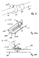
- a parabolic trough collector 10 having an elongate parabolic reflector 11 of parabolic profile.
- the parabolic reflector 11 is provided with an existing framework of a support structure 12.
- an absorber tube 13 which is fixed to supports 14, which are connected to the parabolic reflector.
- the parabolic reflector forms with the supports 14 and the absorber tube 13 a unit which is pivoted about the axis of the absorber tube and thereby the state of the sun S uniaxial tracked.
- the incident of the sun S parallel solar radiation is of the Parabolic reflector 11 focused on the absorber tube 13.
- the absorber tube is traversed by a heat transfer medium, such as water or oil, and heated by the absorbed solar radiation. At the outlet end of the absorber tube, the heat transfer medium can be removed and fed to a heat exchanger or another energy consumer.
- Fig. 2 shows the absorber tube 13, which consists of several pipe sections and is surrounded by cladding tubes 15 made of glass.
- the cladding tubes 15 serve to reduce thermal convection losses and heat radiation losses in the high temperature range.
- the space between the absorber tube 13 and the cladding tube 15 is evacuated.
- the absorber tubing consists of a large number of absorber tubes, which are connected to one another.
- the supports 14 engage.
- the connection points 16 are therefore not covered by the cladding tube 15.
- compensating pieces 17 are welded in the form of a metal bellows to the absorber tube ends.
- the shims 17 ensure a flexible metal-glass transition so as to compensate for the different length expansions.
- a mirror collar 20 surrounding the absorber tube or the cladding tube 15 is disposed in the connecting region between two adjacent cladding tubes 15, which in this exemplary embodiment has a truncated cone shape circulating through 360 °.
- the mirror collar 20 is mirrored on the outside. It has a wide conical end 20a of large diameter and opposite a narrow cone end 20b of smaller diameter. The diameter of the cone end 20b is equal to the outer diameter of the cladding tube 15.
- the mirror collar 20 adjoins the end of the cladding tube 15, and it covers the connection region 50 to the adjacent cladding tube 15 on at least part of the tube length.
- a shim 17 is contained in the cavity enclosed by the mirror collar.
- a second (not shown) mirror collar may be located beyond the junction 16 and cover the other bellows 17. The two mirror collars are then facing each other with their large ends 20a. In between is the support 14.
- the mirror collars 20 have the effect that the incident solar radiation SR is reflected at the conical mirror surface and thrown onto the adjacent absorber tube 13. It can be seen that the solar radiation SR striking the connection region between the tubes is deflected by the mirror collar 20 onto the exposed region of the absorber tube 13 and passes through the jacket tube 15 to the absorber tube. In this way, the energy yield of the parabolic trough collector 10 is improved.
- Fig. 3 shows an embodiment in which the mirror collar 20 extends only about half of the circumference of the cladding tube 15 and has an approximately semicircular conical portion 21, whose ends are connected by a likewise approximately semicircular flat portion 22, so that of the Areas 21 and 22, the cladding tube 15 is encircled by 360 °.
- the conical region 21 has a mirrored reflection surface 23, which deflects the solar radiation SR onto the adjacent region of the absorber tube 13.
- the support 14 can be seen, which holds the absorber tube 13.
- the compensating pieces 17 are arranged, of which only one is visible in Fig. 3, while the other is covered by the mirror collar 20.
- two mirror collars 20 are present, each of which one of Covering shims covered. There is a thermal insulation 25 between the two mirror collars.
- solar collectors are mainly oriented north-south and axially tracked from the east to the west for maximum annual yield. Depending on the location, different angles of incidence from the north or the south occur at different times of the year and day.
- Figures 4-7 show the radiation behavior of a north-south aligned parabolic trough collector at different angles of incidence for a location in southern Europe.
- FIGS. 4-7 The exemplary embodiment of FIGS. 4-7 is based on a mirror collar 20 which has a first conical surface 21 and a second conical surface 24, which are set back-to-back with their large ends.
- the two conical surfaces 21 and 24 are half-cones which extend around half the circumference.
- the double mirror collar 20 according to FIG. 4 extends over the entire connecting region, so that it covers both compensating pieces 17.
- the solar radiation SR falls steeply from the north and primarily meets the north facing large conical surface 21, from which it is reflected on the absorber tube. In this state, the conical surface 24 has no significant reflection effect.
- Fig. 5 shows the radiation behavior of the mirror collar over the day in the summer.
- the reflected radiation strikes the surface almost perpendicular to the day or with a low angle of incidence.
- Both conical surfaces 21 and 24 have a reflective effect.
- Fig. 6 shows the radiation behavior of a double-executed mirror collar in autumn and spring. The radiation comes obliquely from the south and hits both conical surfaces 21 and 24, which reflect the radiation on the absorber tube.
- FIG. 7 shows the radiation behavior of a double mirror collar 20 in winter.
- the radiation is incident with a low angle of incidence from the south, ie substantially parallel to the conical surface 21.
- the radiation impinges with a large angle of incidence on the conical surface 24 and is reflected by this on the absorber tube.
- Fig. 8 shows the angles of attack of the northern and southern mirror collars adapted to the local angles of incidence as follows.
- FIG. 9 schematically shows, in a perspective view, an arrangement with absorber tubes and cladding tubes 15, wherein the connecting region 50 in which the compensating elements are arranged is covered by an insulated radiation protection element.
- This connection region or the insulated radiation protection element 50 has the length L.
- a mirror collar 20 is arranged, which has a planar surface 30 in the form of a vertical to the tube axis employee ring 31 has. H denotes the height of the ring 31.
- Fig. 10a an embodiment is shown with a parabolic reflector 11 having four parabolic segments 11a-11d.
- the focal lines belonging to the parabolic segments are not shown in FIG. 10a, but lie in the region of the absorber tube or cladding tube 15.
- the solar radiation SR is incident at the angle ⁇ , which is also shown in FIG. 10b.
- ⁇ denotes the angle of incidence of the solar radiation
- L the length of the connection region
- V the shading length.
- V is smaller than the length L, so that at the illustrated angle of incidence ⁇ , the cladding tube 15 to the right of the connection region 50 is not shaded.
- a further embodiment of the mirror collar 20 which has a total of six planar surfaces 30 which are arranged inclined to the axis of the cladding tube 15.
- the planar surfaces 30 form facet surfaces on a cone surface.
- the optical efficiency is increased by radiation that would otherwise be incident on the connection region and would be reflected back to the parabolic mirror, in addition to the cladding tube or the absorber tube is directed.
- the mirror collar 20 is mounted on an installation in the northern hemisphere on the south side of the transition area.
- the mirror collar can be arranged at an angle ⁇ of 90 ° as an annular disk 31 up to an angle ⁇ of 45 ° as a mirror collar 20 with planar surfaces 30.
- the profits are highest in winter, for smaller angles the profits increase in the summer, while the profits decrease in the winter.
- the amount of profits and Losses depend on the geographical location, the orientation of the solar collector and the distance of the height of the adjacent solar collectors, which is referred to as horizon shading.
- FIG. 14 shows shading (horizon shading) as a function of local time for 21st March / September.
- the value T on the right-hand y-axis indicates the total shading by the adjacent solar collector (s).
- Figures 15 and 16 show the corresponding curves for 21st June and 21st December.
- Figs. 17 to 19 show respective diagrams for the ratio h / L of 0.55.
- the ratio h / L 0.55 has the result that the shading length V is smaller year-round than the length L of the connection region, as shown in Fig. 10b. This results in only solar gains and losses on the south side of the connection area. It There are no losses due to shading of the absorber pipe on the north side. Losses occur in the summer in the morning and evening hours. During this time, the solar collector is partially shaded by horizon shading, which reduces power-related losses.
- the mirror collar can also be mounted at an angle ⁇ ⁇ 90 ° to the axis of the cladding tube. This increases the profits in the summer half-year and the losses in the morning and evening hours are reduced.
- the individual flat surfaces 30 prevent optical expansion of the focus line.
Landscapes
- Engineering & Computer Science (AREA)
- Chemical & Material Sciences (AREA)
- Life Sciences & Earth Sciences (AREA)
- Sustainable Development (AREA)
- Sustainable Energy (AREA)
- Thermal Sciences (AREA)
- Physics & Mathematics (AREA)
- Combustion & Propulsion (AREA)
- Mechanical Engineering (AREA)
- General Engineering & Computer Science (AREA)
- Optical Elements Other Than Lenses (AREA)
- Photovoltaic Devices (AREA)
- Mounting And Adjusting Of Optical Elements (AREA)
Description
Die Erfindung betrifft einen Solarkollektor mit einem Absorberrohr, mit einem Solarstrahlung auf das Absorberrohr fokussierenden Konzentrator und mit mindestens einem das Absorberrohr umgebenden strahlungsdurchlässigen Hüllrohr, wobei in Verbindungsbereichen zwischen den Hüllrohren Ausgleichsstücke für den Längenausgleich vorgesehen sind.The invention relates to a solar collector with an absorber tube, with a solar radiation focusing on the absorber tube concentrator and with at least one surrounding the absorber tube radiation-permeable cladding tube, wherein compensating pieces are provided for the length compensation in connecting areas between the cladding tubes.
Unter Konzentratoren werden Einrichtungen verstanden, die die Solarstrahlung auf das Absorberrohr fokussieren. Es kann sich hierbei z.B. um optische Einrichtungen handeln. Bevorzugt sind Parabolspiegel, die als Rinne ausgeführt sind. Die an solchen Parabolrinnen reflektierte Strahlung wird in einer Brennlinie konzentriert, in der das Absorberrohr und das Hüllrohr angeordnet sind. Solche Parabolrinnen können auch aus mehreren Rinnensegmenten mit eigenen Krümmungsradien und mit eigenen Brennlinien bestehen.Concentrators are devices that focus the solar radiation on the absorber tube. It may be e.g. to act at optical devices. Preference is given to parabolic mirrors, which are designed as a groove. The radiation reflected at such parabolic troughs is concentrated in a focal line in which the absorber tube and the cladding tube are arranged. Such parabolic troughs can also consist of several channel segments with their own radii of curvature and their own focal lines.
Kommerzielle solare Hochtemperatur-Parabolrinnenkollektoren weisen starke optische Verluste an den Verbindungsbereichen der aus Glas bestehenden Hüllrohre auf. In den Verbindungsbereichen, in denen die Stützen an den Absorberrohren angreifen, sind die Hüllrohre unterbrochen, so dass diese Längenbereiche für die Energieabsorption nicht zur Verfügung stehen. Ein axial der Sonne nachgeführte Parabolrinnenkollektoren konzentrieren die eingestrahlte Solarenergie auf eine Brennlinie. In dieser verläuft ein Absorberrohrstrang, welcher von einem Wärmeübertragungsmedium, in der Regel Thermoöl oder Wasser, durchflossen wird. Ein Großteil der konzentrierten Solarstrahlung wird durch den Absorberrohrstrang in Wärmeenergie umgewandelt und an das Wärmeübertragungsmedium abgegeben. Um thermische Konvektionsverluste im Hochtemperaturbereich zu vermeiden, ist das heiße selektiv beschichtete Absorberrohr durch ein aus Glas bestehendes Hüllrohr umgeben, und der Zwischenraum zwischen Hüllrohr und Absorberrohr ist evakuiert. Aus Statik- und Festigkeitsgründen besteht der Absorberrohrstrang aus einer Vielzahl von Rohrstücken, die hintereinander angeordnet und miteinander verschweißt werden. An den Verbindungsbereichen greifen Metallstützen an, um das Absorberrohr in der Brennlinie des Parabolrinnenkollektors zu halten. Im bestrahlten Zustand dehnt sich das heiße Absorberrohr stärker als das kühlere Hüllrohr aus. Aus diesem Grund sind bei kommerziellen Absorberrohren, wie sie beispielsweise aus der
Kommerzielle solare Hochtemperatur-Parabolrinnenkollektoren weisen an den Absorberrohr-Verbindungsbereichen starke optische Verluste auf. Wegen der Notwendigkeit von flexiblen Glas-Metallübergängen und des Platzbedarfs der Stützen können die Verbindungsbereiche nicht als aktive Absorberrohroberfläche ausgeführt werden, und die ankommende konzentrierte Solarstrahlung kann nicht vom System aufgenommen werden. Durch diesen inaktiven Bereich gehen etwa 5 bis 6% der von den Parabolspiegeln reflektierten Strahlung verloren. Eine Nutzung der im inaktiven Bereich eingestrahlten Strahlung erscheint wegen des sich ständig verändernden Einfallswinkels sehr kompliziert.Commercial solar high-temperature parabolic trough collectors have strong optical losses at the absorber tube junctions. Because of the need for flexible glass-to-metal transitions and the footprint of the posts, the bond areas can not be made as an active absorber tube surface, and the incoming concentrated solar radiation can not be absorbed by the system. About 5 to 6% of the radiation reflected by the parabolic mirrors is lost due to this inactive region. Use of the radiation irradiated in the inactive region appears very complicated because of the constantly changing angle of incidence.
Der Erfindung liegt die Aufgabe zugrunde, einen Solarkollektor mit verbesserter Ausnutzung der einfallenden Strahlungsenergie zu schaffen.The invention has for its object to provide a solar collector with improved utilization of the incident radiation energy.
Der erfindungsgemäße Sonnenkollektor weist die Merkmale des Patentanspruchs 1 auf. Hiernach ist in den Verbindungsbereichen mindestens ein das Hüllrohr umgebender Spiegelkragen angeordnet.The solar collector according to the invention has the features of
Der Spiegelkragen bildet einen Sekundärreflektor, der die konzentrierte Solarstrahlung vom Verbindungsbereich in den Bereich aktiver Absorberrohrfläche reflektiert. Der ganz oder teilweise umlaufende Spiegelkragen hat die Fähigkeit, die aus verschiedenen Richtungen von den Parabolspiegeln kommende konzentrierte Solarstrahlung auch bei verschiedenen Sonneneinfallswinkeln auf die aktive Absorberrohrfläche zu reflektieren. Durch den Spiegelkragen kann zwar ein Teil der Absorberrohrlänge überdeckt werden, jedoch wird die auf diesen Teil treffende Solarstrahlung durch Sekundärreflektion in den absorbierenden Längenbereich des Absorberrohres geleitet.The mirror collar forms a secondary reflector, which reflects the concentrated solar radiation from the connection area into the area of active absorber tube surface. The fully or partially circumferential mirror collar has the ability to reflect the concentrated solar radiation coming from different directions from the parabolic mirrors, even at different angles of incidence of the sun, onto the active absorber tube surface. Although a part of the absorber tube length can be covered by the mirror collar, the solar radiation impinging on this part is guided by secondary reflection into the absorbing length region of the absorber tube.
Gemäß einer ersten Ausführungsform ist in den Verbindungsbereichen ein das Hüllrohr umgebender Spiegelkragen mit einer sich ganz oder teilweise um den Umfang der Hüllrohre erstreckenden Konusform angeordnet.According to a first embodiment, a mirror collar surrounding the cladding tube is arranged in the connecting regions with a cone shape extending wholly or partly around the circumference of the cladding tubes.
Die Konusform des Spiegelkragens bedeutet, dass der Durchmesser des Spiegelkragens sich in Längsrichtung des Absorberrohrs verringert bzw. der Spiegelkragen sich in einer bestimmten Richtung verjüngt. Diese Verjüngung kann kegelförmig sein, jedoch auch von einer Kegelform abweichen, und beispielsweise leicht konkav oder konvex geformt sein.The conical shape of the mirror collar means that the diameter of the mirror collar is reduced in the longitudinal direction of the absorber tube or the mirror collar tapers in a certain direction. This taper can be conical, but also deviate from a conical shape, and be slightly concave or convex, for example.
Es ist auch nicht erforderlich, dass der Spiegelkragen sich über den gesamten Umfang des Hüllrohres bzw. des Absorberrohres erstreckt. Er muss nur den Bereich abdecken, der für den Sonneneinfall in Betracht kommt und aus diesem Bereich die Strahlung auf das abgrenzende Hüllrohr bzw. durch dieses Hüllrohr hindurch auf das Absorberohr lenken.It is also not necessary that the mirror collar extends over the entire circumference of the cladding tube or the absorber tube. It only has to cover the area which is suitable for the sun's rays and from this area direct the radiation onto the delimiting cladding tube or through this cladding tube to the absorber tube.
Der Spiegelkragen kann zwei gegeneinander gesetzte gegensinnige Konusflächen aufweisen. In diesem Fall wird auftreffende Strahlung entweder nach entgegengesetzten Seiten des Absorberrohrs reflektiert, oder ein Teil der Strahlung trifft den Spiegelkragen und ein anderer Teil geht an dem Spiegelkragen vorbei. Die beiden Konusflächen können unterschiedliche Konuswinkel haben. Auf der nördlichen Erdhalbkugel hat vorzugsweise die nach Süden gerichtete Konusfläche den größeren Konuswinkel, während die nach Norden gerichtete Konusfläche einen kleineren Konuswinkel hat. Der Konuswinkel gibt die Steilheit der Konusfläche in Bezug auf die Achse des Absorberrohres an.The mirror collar can have two mutually opposing opposing conical surfaces. In this case, incident radiation is either reflected to opposite sides of the absorber tube, or part of the radiation hits the mirror collar and another part passes by the mirror collar. The two conical surfaces can have different cone angles. In the northern hemisphere, the south-facing cone surface preferably has the larger cone angle, while the north-facing cone surface has a smaller cone angle. The cone angle indicates the steepness of the conical surface with respect to the axis of the absorber tube.
Vorzugsweise ist vorgesehen, dass die Spiegelkragen die Ausgleichsstücke bzw. die Strahlungsschutzelemente in Längsrichtung der Hüllrohre ganz oder teilweise überdecken. Hierbei bildet der Spiegelkragen nicht nur einen Reflektor, sondern auch eine Art Schutzgehäuse für den Verbindungsbereich und die darin enthaltenen Ausgleichsstücke.It is preferably provided that the mirror collars completely or partially cover the compensating pieces or the radiation protection elements in the longitudinal direction of the cladding tubes. Here, the mirror collar not only forms a reflector, but also a kind of protective housing for the connection area and the balance pieces contained therein.
Gemäß einer weiteren Ausführungsform ist vorgesehen, dass der Spiegelkragen mindestens eine plane Fläche aufweist.According to a further embodiment, it is provided that the mirror collar has at least one planar surface.
Plane Flächen haben gegenüber einer Konusfläche den weiteren Vorteil, dass die Strahlung nicht divergent reflektiert wird, sondern dass die Reflektion einer optischen Achsenschrift entspricht. Hierbei bleibt der Focus innerhalb der Brennlinie erhalten, wodurch eine weitere Leistungssteigerung erreicht werden kann.Plane surfaces have the further advantage over a cone surface that the radiation is not divergent reflected, but that the reflection corresponds to an optical axis font. This remains get the focus within the focal line, whereby a further increase in performance can be achieved.
Die plane Fläche ist vorzugsweise senkrecht zur Achse des Hüllrohrs ausgerichtet.The planar surface is preferably aligned perpendicular to the axis of the cladding tube.
Vorzugsweise ist die plane Fläche eine Ringfläche. Die Ringfläche kann sich über den gesamten Umfang des Hüllrohres oder als Teilringfläche nur über einen Abschnitt erstrecken.Preferably, the planar surface is an annular surface. The annular surface may extend over the entire circumference of the cladding tube or as a partial annular surface only over a portion.
Eine bevorzugte Ausführungsform sieht mehrere plane Flächen vor, die auf einem Konus angeordnet sind. Man erhält auf diese Weise plane Facettenflächen, deren Einhüllende einen Kegel bilden. Diese Anordnung ist insbesondere dann von Vorteil, wenn der Konzentrator eine Parabolrinne ist, die aus mehreren Parabolsegmenten besteht, die jeweils eigene Krümmungsradien aufweisen. Vorzugsweise ist jeweils mindestens eine plane Fläche jeweils einem Parabolsegment zugeordnet. Dies bedeutet, dass die plane Fläche derart auf der Konusfäche angeordnet ist, das die zum Parabolsegment gehörende Brennlinie auf der betreffende planen Fläche auftrifft.A preferred embodiment provides a plurality of planar surfaces which are arranged on a cone. Obtained in this way plan facet surfaces whose envelopes form a cone. This arrangement is particularly advantageous when the concentrator is a parabolic trough, which consists of several parabolic segments, each having their own radii of curvature. Preferably, at least one planar surface is assigned to one parabolic segment in each case. This means that the planar surface is arranged on the Konusfäche that impinges the parabolic segment belonging focal line on the relevant plane surface.
Vorzugsweise sind jeweils zwei plane Flächen einem Parabolsegment zugeordnet. Hierbei ist die eine Fläche des Flächenpaares auf dem der Parabolrinne abgewandten Hälfte des Konus und die zweite Fläche auf der der Parabolrinne zugewandten Hälfte des Konus angeordnet.Preferably, two planar surfaces are assigned to a parabolic segment. Here, the one surface of the surface pair on the parabolic trough remote from the half of the cone and the second surface on the parabolic trough facing half of the cone is arranged.
Da vorzugsweise zwei bis vier Parabolsegmente vorgesehen sind, weist der Spiegelkragen dementsprechend vorzugsweise vier bis acht plane Flächen auf.Since preferably two to four parabolic segments are provided, the mirror collar accordingly preferably has four to eight planar surfaces.
Das Verhältnis h durch L liegt vorzugsweise zwischen 0,3 bis 1, wobei h die Höhe des Spiegelkragens senkrecht zur Achse des Hüllrohres und L die Länge des Verbindungsbereiches bezeichnet. Das Verhältnis ist vorzugsweise so zu wählen, dass die Verschattungslänge V ganzjährig kleiner ist als die Länge L des Verbindungsbereiches. Dies hängt wiederum vom Ort, wo der Sonnenkollektor installiert ist und somit vom Winkel der Sonneneinstrahlung, ab.The ratio h through L is preferably between 0.3 to 1, where h is the height of the mirror collar perpendicular to the axis of the cladding tube and L denotes the length of the connection area. The ratio is preferably to be chosen so that the shading length V is smaller year-round than the length L of the connection region. This in turn depends on the location where the solar panel is installed and thus on the angle of solar radiation.
Der Spiegelkragen besteht vorzugsweise aus Aluminium.The mirror collar is preferably made of aluminum.
Im Folgenden werden unter Bezugnahme auf die Zeichnungen Ausführungsbeispiele der Erfindung näher erläutert. Die Beschreibung spezieller Ausführungsbeispiele beschränkt nicht den Schutzbereich der Erfindung.In the following, embodiments of the invention will be explained in more detail with reference to the drawings. The description of specific embodiments does not limit the scope of the invention.
Es zeigen:
- Fig. 1
- eine perspektivische Darstellung eines Parabolrinnenkollektors,
- Fig. 2
- eine Darstellung der Einzelheit II aus Fig. 1 zur Verdeutlichung der Konstruktion des Verbindungsbereiches mit einem umlaufenden Spiegelkragen.
- Fig. 3
- eine Ausführungsform mit einem halbkreisförmigen Spiegelkragen,
- Fig. 4
- eine Ausführungsform mit einem halbkreisförmigen dualen Spiegelkragen,
- Fig. 5, 6 u. 7
- unterschiedliche Situationen des Strahlungseinfalls bei dem Spiegelkragen der Fig. 4,
- Fig. 8
- eine Zeichnung mit Angabe der verschiedenen Längen und Winkel,
- Fig. 9
- eine perspektivische Darstellung einer Absorberrohranordnung mit Hüllrohr und Spiegelkragen mit ebener Fläche,
- Fig. 10a
- eine perspektivische Darstellung eines Parabolrinnenkollektor mit mehreren Parabolsegmenten,
- Fig. 10b
- eine schematische Seitenansicht der in Fig. 9 und 10a gezeigten Anordnung,
- Fig. 11
- einen Spiegelkragen mit mehreren planen Flächen,
- Fig. 12
- die Seitenansicht der in Fig. 11 gezeigten Anordnung und
- Fig. 13
- eine schematische Darstellung der in
den Figuren 11 und 12 dargestellten Anordnung, und - Fig. 14-19
- Diagramme zur Veranschaulichung des solaren Gewinnes.
- Fig. 1
- a perspective view of a parabolic trough collector,
- Fig. 2
- a representation of the detail II of Fig. 1 to illustrate the construction of the connecting portion with a circumferential mirror collar.
- Fig. 3
- an embodiment with a semicircular mirror collar,
- Fig. 4
- an embodiment with a semicircular dual mirror collar,
- Fig. 5, 6 u. 7
- different situations of radiation incidence in the mirror collar of Fig. 4,
- Fig. 8
- a drawing indicating the different lengths and angles,
- Fig. 9
- a perspective view of an absorber tube assembly with cladding tube and mirror collar with a flat surface,
- Fig. 10a
- a perspective view of a parabolic trough collector with several parabolic segments,
- Fig. 10b
- a schematic side view of the arrangement shown in Fig. 9 and 10a,
- Fig. 11
- a mirror collar with several flat surfaces,
- Fig. 12
- the side view of the arrangement shown in Fig. 11 and
- Fig. 13
- a schematic representation of the arrangement shown in Figures 11 and 12, and
- Fig. 14-19
- Diagrams to illustrate the solar gain.
In Fig. 1 ist ein Parabolrinnenkollektor 10 dargestellt, der einen langgestreckten Parabolreflektor 11 von parabelförmigem Profil aufweist. Der Parabolreflektor 11 ist mit einer aus einem Fachwerk bestehenden Tragstruktur 12 versehen. Längs der Brennlinie des Parabolreflektors 11 erstreckt sich ein Absorberrohr 13, das an Stützen 14 befestigt ist, welche mit dem Parabolreflektor verbunden sind. Der Parabolreflektor bildet mit den Stützen 14 und dem Absorberrohr 13 eine Einheit, die um die Achse des Absorberohres geschwenkt und dadurch dem Stand der Sonne S einachsig nachgeführt wird. Die von der Sonne S einfallende parallele Solarstrahlung wird von dem Parabolreflektor 11 auf das Absorberrohr 13 fokussiert. Das Absorberrohr wird von einem Wärmeübertragungsmedium, z.B. Wasser oder Öl, durchflossen und durch die absorbierte Solarstrahlung erhitzt. Am Austrittsende des Absorberrohres kann das Wärmeübertragungsmedium entnommen und einem Wärmeaustauscher oder einem anderen Energieverbraucher zugeführt werden.In Fig. 1, a
Fig. 2 zeigt das Absorberrohr 13, das aus mehreren Rohrabschnitten besteht und von Hüllrohren 15 aus Glas umgeben ist. Die Hüllrohre 15 dienen dazu, thermische Konvektionsverluste und Wärmestrahlungsverluste im Hochtemperaturbereich zu vermindern. Der Zwischenraum zwischen dem Absorberrohr 13 und dem Hüllrohr 15 ist evakuiert. Aus Statik- und Festigkeitsgründen besteht der Absorberrohrstrang aus einer Vielzahl von Absorberrohren, die miteinander verbunden sind. An den Verbindungsstellen 16 greifen jeweils die Stützen 14 an. Die Verbindungsstellen 16 sind daher nicht von dem Hüllrohr 15 bedeckt. Im bestrahlten Zustand dehnt sich das heiße Absorberrohr 13 stärker aus als das kühlere Hüllrohr 15. Aus diesem Grund sind Ausgleichsstücke 17 in Form eines Metallbalges an den Absorberrohrenden eingeschweißt. Die Ausgleichsstücke 17 gewährleisten einen flexiblen Metall-Glasübergang, um so die verschiedenen Längenausdehnungen zu kompensieren.Fig. 2 shows the
Erfindungsgemäß ist in dem Verbindungsbereich zwischen zwei benachbarten Hüllrohren 15 ein das Absorberrohr bzw. das Hüllrohr 15 umgebender Spiegelkragen 20 angeordnet, der bei diesem Ausführungsbeispiel eine um 360° umlaufende Kegelstumpfform hat. Der Spiegelkragen 20 ist außen verspiegelt. Er weist ein breites Konusende 20a großen Durchmessers und gegenüberliegend ein schmales Konusende 20b kleineren Durchmessers auf. Der Durchmesser des Konusendes 20b ist gleich dem Außendurchmesser des Hüllrohrs 15. Der Spiegelkragen 20 schließt sich an das Ende des Hüllrohrs 15 an, und er bedeckt den Verbindungsbereich 50 zum benachbarten Hüllrohr 15 auf mindestens einem Teil der Rohrlänge. Bei dem vorliegenden Ausführungsbeispiel ist ein Ausgleichsstück 17 in dem von dem Spiegelkragen umschlossenen Hohlraum enthalten. Ein zweiter (nicht dargestellter) Spiegelkragen kann sich jenseits der Verbindungsstelle 16 befinden und den anderen Faltenbalg 17 bedecken. Die beiden Spiegelkragen sind dann mit ihren großen Enden 20a einander zugewandt. Dazwischen befindet sich die Stütze 14.According to the invention, a
Die Spiegelkragen 20 haben die Wirkung, dass die einfallende Sonnenstrahlung SR an der konischen Spiegelfläche reflektiert und auf das angrenzende Absorberrohr 13 geworfen wird. Man erkennt, dass die dem Verbindungsbereich zwischen den Rohren auftreffende Solarstrahlung SR durch den Spiegelkragen 20 auf den exponierten Bereich des Absorberrohres 13 umgelenkt wird und durch das Hüllrohr 15 hindurch zum Absorberrohr gelangt. Auf diese Weise wird die Energieausbeute des Parabolrinnenkollektors 10 verbessert.The
Fig. 3 zeigt ein Ausführungsbeispiel, bei dem der Spiegelkragen 20 sich nur etwa um die Hälfte des Umfangs des Hüllrohres 15 erstreckt und einen etwa halbkreisförmigen kegelförmigen Bereich 21 aufweist, dessen Enden durch einen ebenfalls etwa halbkreisförmigen flachen Bereich 22 verbunden sind, so dass von den Bereichen 21 und 22 das Hüllrohr 15 um 360° umfangen wird. Der kegelförmige Bereich 21 weist eine verspiegelte Reflektionsfläche 23 auf, die die Sonnenstrahlung SR auf den angrenzenden Bereich des Absorberrohres 13 umlenkt. In Fig. 3 ist die Stütze 14 erkennbar, die das Absorberrohr 13 hält. Beidseitig der Stütze 14 sind die Ausgleichsstücke 17 angeordnet, von denen in Fig. 3 nur eines sichtbar ist, während das andere von dem Spiegelkragen 20 verdeckt ist. Im fertigen Zustand sind zwei Spiegelkragen 20 vorhanden, von denen jeder eines der Ausgleichsstücke bedeckt. Zwischen den beiden Spiegelkragen befindet sich eine thermische Isolierung 25.Fig. 3 shows an embodiment in which the
In der Praxis werden Solarkollektoren hauptsächlich in Nord-Süd-Richtung ausgerichtet und axial der Sonne von Osten nach Westen nachgeführt, um den maximalen jährlichen Ertrag zu erzielen. Zu verschiedenen Jahres- und Tageszeiten ergeben sich standortabhängig unterschiedliche Einfallswinkel aus nördlicher bzw. südlicher Richtung. Die Figuren 4-7 zeigen das Strahlungsverhalten eines Nord-Süd ausgerichteten Parabolrinnenkollektors bei unterschiedlichen Einfallswinkeln für einen Standort in Südeuropa.In practice, solar collectors are mainly oriented north-south and axially tracked from the east to the west for maximum annual yield. Depending on the location, different angles of incidence from the north or the south occur at different times of the year and day. Figures 4-7 show the radiation behavior of a north-south aligned parabolic trough collector at different angles of incidence for a location in southern Europe.
Dem Ausführungsbeispiel der Figuren 4 - 7 liegt ein Spiegelkragen 20 zugrunde, der eine erste Konusfläche 21 und eine zweite Konusfläche 24 aufweist, welche mit ihren großen Enden Rücken an Rücken gegeneinander gesetzt sind. Die beiden Konusflächen 21 und 24 sind Halbkegel, die sich um den halben Umfang erstrecken. Der doppelte Spiegelkragen 20 nach Fig. 4 erstreckt sich über den gesamten Verbindungsbereich, so dass er beide Ausgleichsstücke 17 überdeckt.The exemplary embodiment of FIGS. 4-7 is based on a
Der Sachverhalt, dass im Idealfall auch bei verschiedenen Einfallswinkeln die gesamte aus verschiedenen Richtungen von den Parabolspiegeln kommende konzentrierte Strahlung auf die Brennlinie trifft, hat zur Folge, dass auch bei verschiedenen Einfallswinkeln am Absorberrohr ein sternförmiger und daher rotationssymmetrischer Einstrahlungsfall vorliegt, dessen Rotationsachse mit der Brennlinie im Absorberrohr zusammenfällt. Da der Spiegelkragen im Prinzip rotationssymmetrisch zur Brennlinie ausgeführt ist, ist der in den Figuren 4 - 7 eingezeichnete Strahlengang aus rotationssymmetrischen Gründen repräsentativ für alle anderen radial einfallenden Strahlengänge.The fact that ideally also at different angles of incidence the entire concentrated radiation coming from different directions from the parabolic mirrors strikes the focal line has the consequence that even at different angles of incidence on the absorber tube there is a star-shaped and therefore rotationally symmetric irradiation case whose axis of rotation coincides with the focal line collapses in the absorber tube. Since the mirror collar is in principle rotationally symmetrical to the focal line, the beam path drawn in FIGS. 4-7 is representative of all other radially incident beam paths for rotationally symmetrical reasons.
Fig. 4 zeigt das Strahlungsverhalten eines doppelt ausgeführten Spiegelkragens 20 am Morgen und am Abend im Sommer. Die Solarstrahlung SR fällt steil von Norden her ein and trifft vornehmlich auf die nach Norden gewandte große Kegelfläche 21, von der sie auf das Absorberrohr reflektiert wird. In diesem Zustand hat die Kegelfläche 24 keine wesentliche Reflektionswirkung.4 shows the radiation behavior of a
Fig. 5 zeigt das Strahlungsverhalten des Spiegelkragens über den Tag im Sommer. Im Sommer trifft die reflektierte Strahlung fast über den ganzen Tag senkrecht oder mit geringem Einfallswinkel auf. Beide Kegelflächen 21 und 24 wirken reflektierend.Fig. 5 shows the radiation behavior of the mirror collar over the day in the summer. In the summer, the reflected radiation strikes the surface almost perpendicular to the day or with a low angle of incidence. Both
Fig. 6 zeigt das Strahlungsverhalten eines doppelt ausgeführten Spiegelkragens im Herbst und Frühjahr. Die Strahlung kommt schräg aus südlicher Richtung und trifft beide Kegelflächen 21 und 24, die die Strahlung auf das Absorberrohr reflektieren.Fig. 6 shows the radiation behavior of a double-executed mirror collar in autumn and spring. The radiation comes obliquely from the south and hits both
Fig. 7 zeigt das Strahlungsverhalten eines doppelt ausgeführten Spiegelkragens 20 im Winter. Die Strahlung fällt mit geringem Einfallswinkel von Süden her ein, also im wesentlichen parallel zu der Kegelfläche 21. Die Strahlung trifft mit großem Einfallswinkel auf die Kegelfläche 24 und wird von dieser auf das Absorberrohr reflektiert.FIG. 7 shows the radiation behavior of a
Fig. 8 zeigt die Anstellwinkel des nördlichen und südlichen Spiegelkragens, die den lokalen Einfallswinkeln wie folgt angepasst werden.Fig. 8 shows the angles of attack of the northern and southern mirror collars adapted to the local angles of incidence as follows.
Es bedeuten
- α1 = Anstellwinkel des Nordspiegelkragens
- α2 = Anstellwinkel des Südspiegelkragens
- φ = Sonneneinfallswinkel
- β1 = nördliche Absorberauftreffwinkel der vom Kragen reflektierten Strahlung
- β2 = südliche Absorberauftreffwinkel der vom Kragen reflektierten Strahlung
- h = Kragenhöhe
- L = Länge des Absorberrohrverbindungsstücks = Länge des Verbindungsbereichs
- α1 = angle of attack of the north mirror collar
- α2 = angle of attack of the south mirror collar
- φ = sun angle of incidence
- β1 = northern absorber angle of incidence of the radiation reflected by the collar
- β2 = southern absorber angle of incidence of the radiation reflected by the collar
- h = collar height
- L = length of the absorber tube connector = length of the connection area
Daraus ergeben sich gemäß Fig. 8 die folgenden Beziehungen: ![]()
![]()

![]()
![]()
Für den Standort Südeuropa liegen die Einfallswinkel hauptsächlich zwischen Φ = -20° und Φ = +60°. In diesem Intervall wird etwa 97% der Solarenergie auf den Kollektor eingestrahlt. Berücksichtigt man einen Auftreffwinkel von etwa 10° für noch ausreichend bei extremen Einfallswinkeln, so ergibt sich nach den in Fig. 8 dargestellten Abhängigkeiten ein nördlicher Anstellwinkel von α1 = 60° und ein südlicher Anstellwinkel von α2 = 80° für den Spiegelkragen. In einem Parabolrinnenkraftwerk wird der Großteil der Solarenergie im Bereich von Φ = 10° bis Φ = 20° eingestrahlt. In diesem Bereich ergeben sich für die beschriebenen Anstellwinkel relativ große Auftreffwinkel von 50° bis 60°. Bei großen Auftreffwinkeln ist die Distanz zwischen dem Spiegelkragen und dem aktiven Absorberrohr geringer und die Treffsicherheit des Spiegelkragens größer.For the location Southern Europe the angles of incidence are mainly between Φ = -20 ° and Φ = + 60 °. In this interval, about 97% of the solar energy is radiated onto the collector. If one considers an angle of incidence of approximately 10 ° for still sufficiently at extreme angles of incidence, then, according to the dependencies shown in FIG. 8, a northern angle of attack of α1 = 60 ° and a southern angle of attack of α2 = 80 ° for the mirror collar. In a parabolic trough power plant, most of the solar energy is radiated in the range of Φ = 10 ° to Φ = 20 °. In this area arise for the angle of attack described relatively large incidence angle of 50 ° to 60 °. At large angles of incidence, the distance between the mirror collar and the active absorber tube is less and the accuracy of the mirror collar is greater.
In der Fig. 9 ist schematisch in perspektivischer Darstellung eine Anordnung mit Absorberrohren und Hüllrohren 15 dargestellt, wobei der Verbindungsbereich 50, in dem die Ausgleichselemente angeordnet sind, durch ein isoliertes Strahlungsschutzelement abgedeckt ist. Dieser Verbindungsbereich bzw. das isolierte Strahlungsschutzelement 50 besitzt die Länge L. Am linken Ende des Verbindungsbereiches 50, das dem südlichen Ende des Verbindungsbereichs 50 bei einer Installation auf der Nordhalbkugel entspricht, ist ein Spiegelkragen 20 angeordnet, der eine plane Fläche 30 in Form eines senkrecht zur Rohrachse angestellten Ringes 31 aufweist. Mit h wird die Höhe des Rings 31 bezeichnet.FIG. 9 schematically shows, in a perspective view, an arrangement with absorber tubes and
In der Fig. 10a ist eine Ausführungsform mit einem Parabolreflektor 11 dargestellt, der vier Parabolsegmente11a -11d aufweist. Die zu den Parabolsegmenten gehörenden Brennlinien sind in der Fig. 10a nicht dargestellt, liegen jedoch im Bereich des Absorberrohrs bzw. Hüllrohrs 15. Die Solarstrahlung SR fällt unter dem Winkel α ein, der auch in der Figur 10b eingezeichnet ist.In Fig. 10a, an embodiment is shown with a
In der Fig. 10b sind zur Veranschaulichung der mathematischen Beziehung V = h x tan(α) die in den Fig. 9 und 10a dargestellte Anordnung schematisch in Seitenansicht zu sehen. α bezeichnet den Einfallswinkel der Solarstrahlung, L die Länge des Verbindungsbereichs und V die Verschattungslänge. Bei der in Fig. 10b gezeigten Anordnung ist V kleiner als die Länge L, so dass bei dem dargestellten Einfallswinkel α das Hüllrohr 15 rechts vom Verbindungsbereich 50 nicht abgeschattet wird.In FIG. 10b, to illustrate the mathematical relationship V = hx tan (α), the arrangement shown in FIGS. 9 and 10a is shown schematically in side view. α denotes the angle of incidence of the solar radiation, L the length of the connection region and V the shading length. In the arrangement shown in FIG. 10b, V is smaller than the length L, so that at the illustrated angle of incidence α, the
In der Fig. 11 ist eine weitere Ausführungsform des Spiegelkragens 20 dargestellt, der insgesamt sechs plane Flächen 30 aufweist, die zur Achse des Hüllrohrs 15 geneigt angeordnet sind. Die planen Flächen 30 bilden Facettenflächen auf einer Konusfläche.11, a further embodiment of the
In der Fig. 12 ist diese Anordnung noch einmal in Seitenansicht dargestellt, wobei zusätzlich die einfallende Solarstrahlung SR eingezeichnet ist.In Fig. 12, this arrangement is again shown in side view, wherein in addition the incident solar radiation SR is located.
In der Fig. 13 ist diese Anordnung zur Verdeutlichung der mathematischen Beziehungen noch einmal in Seitenansicht dargestellt. Die Verschattungslänge V ergibt sich aus V = c + d = h (sinβ + cosβ • tanα), wobei β die Neigung des Spiegelkragens 20 bzw. die Neigung der planen Flächen 30 des Spiegelkragens 20 bezeichnet.In FIG. 13, this arrangement is again shown in side view to illustrate the mathematical relationships. The shading length V is given by V = c + d = h (sinβ + cosβ · tanα), where β denotes the inclination of the
Durch Anbringen eines solchen mit planen Flächen versehenen Spiegelkragens im Verbindungsbereich 50 zwischen zwei benachbarten Rohren wird der optische Wirkungsgrad gesteigert, indem Strahlung, die sonst auf den Verbindungsbereich auftrifft und zum Parabolspiegel zurückreflektiert würde, zusätzlich auch auf das Hüllrohr bzw. das Absorberrohr gelenkt wird.By attaching such a flat collar provided with the mirror collar in the
Der Spiegelkragen 20 wird bei einer Installation auf der Nordhalbkugel auf der Südseite des Übergangsbereiches angebracht. Der Spiegelkragen kann unter dem Winkel β von 90° als Ringscheibe 31 bis zu einem Winkel β von 45° als Spiegelkragen 20 mit planen Flächen 30 angeordnet werden.The
Bei einem Winkel β von 90° sind die Gewinne im Winter am höchsten, für kleinere Winkel erhöhen sich die Gewinne im Sommer, während sich die Gewinne im Winter verkleinern. Die Höhe der Gewinne und Verluste ist von der geographischen Lage, der Orientierung des Solarkollektors und vom Abstand der Höhe der benachbarten Solarkollektoren abhängig, was als Horizontverschattung bezeichnet wird.At an angle β of 90 °, the profits are highest in winter, for smaller angles the profits increase in the summer, while the profits decrease in the winter. The amount of profits and Losses depend on the geographical location, the orientation of the solar collector and the distance of the height of the adjacent solar collectors, which is referred to as horizon shading.
Das folgende Fallbeispiel wurde für den Standort Malaga, Nordsüdausrichtung des Solarkollektors und einer Horizontverschattung von 15° berechnet.The following case example was calculated for the location of Malaga, north-south orientation of the solar collector and a horizon shading of 15 °.
In der Fig. 14 ist die Abschattung (Horizontverschattung) in Abhängigkeit von der Ortszeit für den 21. März/September dargestellt. Der Wert T auf der rechten y-Achse bezeichnet die totale Verschattung durch den oder die benachbarten Solarkollektoren.FIG. 14 shows shading (horizon shading) as a function of local time for 21st March / September. The value T on the right-hand y-axis indicates the total shading by the adjacent solar collector (s).
Ohne Berücksichtigung der Horizontverschattung erhält man die Kurve, die als "solarer Gewinn ohne Abschattung" bezeichnet wird. Berücksichtigt man die Abschattung (Horizontverschattung) so erhält man die durchgezogene Kurve, die den effektiven solaren Gewinn darstellt. Hierbei wurde ein Verhältnis von h durch L von 0,5 gewählt. Der solare Gewinn ist auf die absorbierte Energie einer Anordnung ohne Spiegelkragen bezogen.Without considering the shading of the horizon you get the curve, which is called "solar gain without shading". Taking into account the shading (horizon shading) one obtains the solid curve, which represents the effective solar gain. Here, a ratio of h to L of 0.5 was chosen. The solar gain is related to the absorbed energy of an arrangement without a mirror collar.
Die Fig. 15 und 16 zeigen die entsprechenden Kurven für den 21. Juni und für den 21. Dezember.Figures 15 and 16 show the corresponding curves for 21st June and 21st December.
Die Fig. 17 bis 19 zeigen entsprechende Diagramme für das Verhältnis h/L von 0,55.Figs. 17 to 19 show respective diagrams for the ratio h / L of 0.55.
Das Verhältnis h/L = 0,55 hat zur Folge, dass die Verschattungslänge V ganzjährig kleiner ist als die Länge L des Verbindungsbereiches, wie dies in der Fig. 10b dargestellt ist. Dadurch entstehen nur solare Gewinne und Verluste auf der Südseite des Verbindungsbereiches. Es entstehen keine Verluste durch Verschattung des Absorberrohres auf der Nordseite. Verluste entstehen im Sommer in den Morgen- und Abendstunden. In dieser Zeit ist der Solarkollektor durch die Horizontverschattung teilverschattet, wodurch sich.die leistungsbezogenen Verluste vermindern.The ratio h / L = 0.55 has the result that the shading length V is smaller year-round than the length L of the connection region, as shown in Fig. 10b. This results in only solar gains and losses on the south side of the connection area. It There are no losses due to shading of the absorber pipe on the north side. Losses occur in the summer in the morning and evening hours. During this time, the solar collector is partially shaded by horizon shading, which reduces power-related losses.
Am 21. Juni sind Gewinne und Verluste etwa gleich groß. Für alle anderen Tage vergrößern sich die Gewinne und verringern sich die Verluste. Im Winterhalbjahr gibt es nur Gewinne auf der Südseite. Ist das Verhältnis h durch L größer 0,55, so erhöhen sich die Gewinne im Sommerhalbjahr. Gleichzeitig entstehen im Winterhalbjahr Verluste durch Verschattung des Absorberrohrs auf der Nordseite.On June 21, profits and losses are about the same size. For all other days, profits increase and losses decrease. In the winter months, there are only profits on the south side. If the ratio h by L is greater than 0.55, the profits increase in the summer half-year. At the same time, losses occur in the winter half-year due to shading of the absorber pipe on the north side.
Der Spiegelkragen kann auch in einem Winkel β < 90° zur Achse des Hüllrohrs montiert werden. Hierdurch erhöhen sich die Gewinne im Sommerhalbjahr und die Verluste in den Morgen- und Abendstunden werden verringert. Durch die einzelnen planen Flächen 30 wird eine optische Aufweitung der Fokuslinie verhindert.The mirror collar can also be mounted at an angle β <90 ° to the axis of the cladding tube. This increases the profits in the summer half-year and the losses in the morning and evening hours are reduced. The individual
In den Fig. 20 bis 22 sind die effektiven solaren Gewinnkurven für unterschiedliche Verhältnisse h/L für drei Werte, nämlich h/L = 0,55, h/L = 0,8 und h/L = 1 dargestellt. In der Fig. 22 sind zusätzlich noch die Gewinne auf der Südseite für 0,8 und für h/L = 1 dargestellt.FIGS. 20 to 22 show the effective solar gain curves for different ratios h / L for three values, namely h / L = 0.55, h / L = 0.8 and h / L = 1. In addition, the profits on the south side for 0.8 and for h / L = 1 are also shown in FIG.
- 1010
- Parabolrinnenkollektorparabolic trough collector
- 1111
- Parabolreflektorparabolic
- 11a-d11a-d
- ParabolsegmenteParabolsegmente
- 1212
- Tragstruktursupporting structure
- 1313
- Absorberrohrabsorber tube
- 1414
- Stützesupport
- 1515
- Hüllrohrcladding tube
- 1717
- Ausgleichsstückeshims
- 2020
- Spiegelkragenmirror collar
- 20a20a
- breites Konusendewide cone end
- 20b20b
- schmales Konusendenarrow cone end
- 21,2421.24
- Konusflächencone surfaces
- 2222
- flacher Bereichflat area
- 2323
- Reflektionsflächereflecting surface
- 3030
- Flächearea
- 3131
- Ringflächering surface
- 5050
- Verbindungsbereichconnecting area
- SS
- SonneSun
- SRSR
- Sonnenstrahlungsolar radiation
Claims (7)
- Parabolic trough collector with an absorber tube (13) which is attached to supports (14), a parabolic reflector (11) which focuses solar radiation onto the absorber tube (13), and a plurality of radiation-transmissive cladding tubes (15) surrounding the absorber tube (13), compensating pieces (17) for length compensation being provided in connecting regions between the cladding tubes (15), characterized in that a mirror collar (20), which surrounds the cladding tube (15) and has the shape of a cone extending completely or partly around the circumference of the cladding tubes (15), is arranged in the connecting regions (50).
- Parabolic trough collector according to Claim 1, characterized in that the mirror collar (20) comprises two conical surfaces (21, 24) positioned opposite one another and in opposite directions.
- Parabolic trough collector according to Claim 2, characterized in that the conical surfaces (21, 24) have different cone angles.
- Parabolic trough collector according to one of Claims 1-3, characterized in that the mirror collars (20) completely or partly cover the compensating pieces (17) in the longitudinal direction of the cladding tubes (15).
- Parabolic trough collector according to Claim 4, characterized in that two mirror collars (20) positioned opposite one another envelope a connecting region over its entire length.
- Parabolic trough collector according to one of Claims 1-5, characterized in that the mirror collar (20) extends around approximately half the circumference of the cladding tube (15).
- Parabolic trough collector according to one of Claims 1-6, characterized in that the parabolic reflector (11) tracks the position of the sun about a single axis.
Applications Claiming Priority (2)
| Application Number | Priority Date | Filing Date | Title |
|---|---|---|---|
| DE10351474A DE10351474B3 (en) | 2003-11-04 | 2003-11-04 | parabolic trough collector |
| EP04797618A EP1690047B1 (en) | 2003-11-04 | 2004-11-04 | Solar collector |
Related Parent Applications (1)
| Application Number | Title | Priority Date | Filing Date |
|---|---|---|---|
| EP04797618A Division EP1690047B1 (en) | 2003-11-04 | 2004-11-04 | Solar collector |
Publications (2)
| Publication Number | Publication Date |
|---|---|
| EP1712852A1 EP1712852A1 (en) | 2006-10-18 |
| EP1712852B1 true EP1712852B1 (en) | 2007-08-22 |
Family
ID=34428554
Family Applications (2)
| Application Number | Title | Priority Date | Filing Date |
|---|---|---|---|
| EP04797618A Expired - Lifetime EP1690047B1 (en) | 2003-11-04 | 2004-11-04 | Solar collector |
| EP06016603A Expired - Lifetime EP1712852B1 (en) | 2003-11-04 | 2004-11-04 | Solar collector |
Family Applications Before (1)
| Application Number | Title | Priority Date | Filing Date |
|---|---|---|---|
| EP04797618A Expired - Lifetime EP1690047B1 (en) | 2003-11-04 | 2004-11-04 | Solar collector |
Country Status (7)
| Country | Link |
|---|---|
| US (2) | US7240675B2 (en) |
| EP (2) | EP1690047B1 (en) |
| CN (1) | CN100529583C (en) |
| DE (2) | DE10351474B3 (en) |
| ES (2) | ES2251320B1 (en) |
| IL (1) | IL175167A0 (en) |
| WO (1) | WO2005045329A1 (en) |
Families Citing this family (38)
| Publication number | Priority date | Publication date | Assignee | Title |
|---|---|---|---|---|
| DE10351474B3 (en) * | 2003-11-04 | 2005-05-12 | Deutsches Zentrum für Luft- und Raumfahrt e.V. | parabolic trough collector |
| US20110030672A1 (en) * | 2006-07-14 | 2011-02-10 | Olsson Mark S | Solar Collection Apparatus and Methods Using Accelerometers and Magnetics Sensors |
| CN100513926C (en) * | 2006-08-28 | 2009-07-15 | 中国科学院电工研究所 | High-temperature solar thermal-collecting tube and manufacturing process thereof |
| DE102006056536B9 (en) * | 2006-11-27 | 2008-06-05 | Schott Ag | Radiation-selective absorber coating, absorber tube and method for its production |
| EP2252840A2 (en) * | 2008-02-20 | 2010-11-24 | Corning Incorporated | Solar heat collection element with glass-ceramic central tube |
| US7810940B2 (en) * | 2008-06-03 | 2010-10-12 | Areva Solar, Inc. | Adjustable table for shaping a mirror |
| US7765705B2 (en) * | 2008-06-03 | 2010-08-03 | Areva Solar, Inc. | Methods and devices for characterizing a surface |
| EP2310763B1 (en) * | 2008-06-11 | 2016-11-23 | SRB Energy Research SÀRL | Evacuated solar panel with a non evaporable getter pump |
| US8341960B2 (en) * | 2008-06-30 | 2013-01-01 | Ormat Technologies, Inc. | Multi-heat source power plant |
| US8266908B2 (en) * | 2008-06-30 | 2012-09-18 | Ormat Technologies, Inc. | Multi-heat source power plant |
| US20100043779A1 (en) * | 2008-08-20 | 2010-02-25 | John Carroll Ingram | Solar Trough and Receiver |
| US8049150B2 (en) * | 2009-01-12 | 2011-11-01 | Skyline Solar, Inc. | Solar collector with end modifications |
| AU2010226650B2 (en) * | 2009-03-17 | 2013-08-15 | D & D Manufacturing | Stationary parabolic solar power system and related methods for collecting solar energy |
| US8091544B1 (en) | 2009-06-10 | 2012-01-10 | Lockheed Martin Corporation | Solar light collector assembly having a clamp arrangement for attaching a mirror to a frame truss |
| DE102009049471B3 (en) * | 2009-10-15 | 2011-04-07 | Schott Solar Ag | Radiation-selective absorber coating and absorber tube with radiation-selective absorber coating |
| DE102009046064B4 (en) * | 2009-10-27 | 2014-03-06 | Schott Solar Ag | Absorber tube and method for reversibly loading and unloading a getter material |
| EP2580533A4 (en) * | 2010-04-15 | 2014-10-01 | Axisol Inc | SOLAR SENSORS |
| GB201008032D0 (en) * | 2010-05-14 | 2010-06-30 | Dow Corning | Solar reflection apparatus |
| CN113776203A (en) | 2010-09-16 | 2021-12-10 | 威尔逊太阳能公司 | Concentrator for solar receiver |
| CN101951197B (en) * | 2010-09-30 | 2012-04-18 | 北京印刷学院 | Closed cavity hemisphere lighting spotlight multiplication solar power generation device |
| CN101951201B (en) * | 2010-09-30 | 2012-06-27 | 北京印刷学院 | Light-collecting solar power generation device with secondary reflection disc closed cavity |
| CN101964614B (en) * | 2010-10-25 | 2012-04-18 | 北京印刷学院 | Parabolic cylinder light-gathering parabolic cylinder closed cavity daylighting solar generating set |
| JP5695894B2 (en) | 2010-12-15 | 2015-04-08 | 株式会社日立製作所 | Solar collector |
| US8584666B2 (en) * | 2011-05-12 | 2013-11-19 | Lockheed Martin Corporation | Prism shields for a parabolic trough solar collector |
| US20130092155A1 (en) | 2011-10-14 | 2013-04-18 | Florida Power & Light Company | Focal display panel for visual optimization of solar collection |
| EP2769153A4 (en) * | 2011-10-20 | 2015-07-15 | Abengoa Solar Llc | Heat transfer fluid heating system and method for a parabolic trough solar concentrator |
| EP2909547B1 (en) | 2012-03-21 | 2021-09-15 | Wilson 247Solar, Inc. | Solar receiver |
| US9689957B2 (en) * | 2012-05-29 | 2017-06-27 | Solarcity Corporation | Solar tracking system using periodic scan patterns with a shielding tube |
| WO2013178370A2 (en) * | 2012-06-01 | 2013-12-05 | Siemens Aktiengesellschaft | Solar reciver tube wit low emissivity covering, method for manufacturing the solar receiver tube and use of the tube |
| CN102980315B (en) * | 2012-11-21 | 2015-07-01 | 皇明太阳能股份有限公司 | Reflecting device of trough-type focusing solar thermal collector |
| DE102013201409B3 (en) | 2013-01-29 | 2014-07-10 | Schott Solar Ag | Holding device for absorber tubes |
| DE102013201939A1 (en) * | 2013-02-06 | 2014-08-07 | Sunoyster Systems Gmbh | solar system |
| US10145365B2 (en) | 2013-03-20 | 2018-12-04 | Brenmiller Energy Ltd. | Integrated thermal storage, heat exchange, and steam generation |
| US9423155B2 (en) | 2013-09-30 | 2016-08-23 | Do Sun Im | Solar energy collector and system for using same |
| DE202014101727U1 (en) | 2014-04-11 | 2015-07-14 | Schott Ag | mirror collar |
| DE102014213061B4 (en) | 2014-07-04 | 2017-07-27 | Rioglass Solar Holding, S.A. | Mirror collar set, receiver tube and solar collector |
| US10845091B2 (en) | 2018-05-17 | 2020-11-24 | Universidad Nacional de Itapua | Elliptical cylinder collector for solar thermal energy |
| CN108593351A (en) * | 2018-06-28 | 2018-09-28 | 南京信息工程大学 | A kind of novel water sample acquisition device and water sampling depth adjustment method |
Family Cites Families (28)
| Publication number | Priority date | Publication date | Assignee | Title |
|---|---|---|---|---|
| US1081963A (en) * | 1913-03-19 | 1913-12-23 | Jesse A Holloway | Hose-coupling. |
| US1184216A (en) * | 1915-04-02 | 1916-05-23 | Halbert E Smith | Train-pipe coupling. |
| US2133649A (en) * | 1935-03-27 | 1938-10-18 | Abbot Charles Greeley | Solar heater |
| US3333871A (en) * | 1965-03-18 | 1967-08-01 | Screw Machine Products Co | Conduit fittings |
| US3837685A (en) * | 1973-01-02 | 1974-09-24 | J Miller | Pipe expansion and repair fitting |
| US3916871A (en) * | 1973-06-26 | 1975-11-04 | James M Estes | Flat plate solar collector module |
| US4133298A (en) * | 1975-09-26 | 1979-01-09 | Sanyo Electric Co., Ltd. | Solar heat collecting apparatus |
| US4173968A (en) * | 1976-05-17 | 1979-11-13 | Steward Willis G | Receiver for solar energy |
| US4202322A (en) * | 1977-05-11 | 1980-05-13 | Del Manufacturing Company | Solar energy collector and heat exchanger |
| US4231353A (en) * | 1977-05-13 | 1980-11-04 | Sanyo Electric Co., Ltd. | Solar heat collecting apparatus |
| US4295462A (en) * | 1977-06-13 | 1981-10-20 | Bunch Jesse C | Energy concentrator system |
| CH626160A5 (en) * | 1977-10-14 | 1981-10-30 | Bogatzki Hans Ulrich | |
| US4186725A (en) * | 1978-03-29 | 1980-02-05 | Schwartz David M | Solar energy collector |
| US4337758A (en) * | 1978-06-21 | 1982-07-06 | Meinel Aden B | Solar energy collector and converter |
| JPS5952739B2 (en) * | 1979-09-05 | 1984-12-21 | 日本電気硝子株式会社 | Solar heat collector tube and its manufacturing method |
| US4350372A (en) * | 1980-01-21 | 1982-09-21 | Logsdon Duane D | Expansion coupling for large diameter plastic pipes |
| US4432343A (en) * | 1980-03-03 | 1984-02-21 | Viking Solar Systems, Incorporated | Solar energy collector system |
| JPS56155333A (en) * | 1980-04-30 | 1981-12-01 | Haneichi Yoshioka | Solar energy collector |
| US4283078A (en) * | 1980-05-01 | 1981-08-11 | Ross Victor H | Flexible joint protector |
| US4304222A (en) * | 1980-08-18 | 1981-12-08 | Novinger Harry E | Low profile evacuated-bottle solar collector module |
| US4438759A (en) * | 1980-12-24 | 1984-03-27 | Matsushita Electric Industrial Co., Ltd. | Heat-pipe type solar water heater |
| AU569478B2 (en) * | 1982-09-30 | 1988-02-04 | Solar Engineering Pty. Ltd. | Solar apparatus |
| DE4331784C2 (en) * | 1993-09-18 | 1997-10-23 | Deutsche Forsch Luft Raumfahrt | Channel collector |
| US5555878A (en) * | 1995-01-30 | 1996-09-17 | Sparkman; Scott | Solar energy collector |
| DE19840181B4 (en) * | 1998-09-03 | 2005-04-14 | Deutsches Zentrum für Luft- und Raumfahrt e.V. | Parabolic trough collector for a solar power plant |
| US6705311B1 (en) * | 2001-11-13 | 2004-03-16 | Solel Solar Systems Ltd. | Radiation heat-shield for solar system |
| DE10231467B4 (en) * | 2002-07-08 | 2004-05-27 | Schott Glas | Absorber tube for solar thermal applications |
| DE10351474B3 (en) * | 2003-11-04 | 2005-05-12 | Deutsches Zentrum für Luft- und Raumfahrt e.V. | parabolic trough collector |
-
2003
- 2003-11-04 DE DE10351474A patent/DE10351474B3/en not_active Expired - Fee Related
-
2004
- 2004-10-15 ES ES200402446A patent/ES2251320B1/en not_active Expired - Fee Related
- 2004-11-01 US US10/978,300 patent/US7240675B2/en active Active
- 2004-11-04 CN CNB2004800324607A patent/CN100529583C/en not_active Expired - Lifetime
- 2004-11-04 DE DE502004003248T patent/DE502004003248D1/en not_active Expired - Lifetime
- 2004-11-04 US US10/578,035 patent/US7637259B2/en active Active
- 2004-11-04 EP EP04797618A patent/EP1690047B1/en not_active Expired - Lifetime
- 2004-11-04 ES ES04797618T patent/ES2281844T3/en not_active Expired - Lifetime
- 2004-11-04 WO PCT/EP2004/012493 patent/WO2005045329A1/en active IP Right Grant
- 2004-11-04 EP EP06016603A patent/EP1712852B1/en not_active Expired - Lifetime
-
2006
- 2006-04-25 IL IL175167A patent/IL175167A0/en active IP Right Grant
Also Published As
| Publication number | Publication date |
|---|---|
| US7637259B2 (en) | 2009-12-29 |
| EP1712852A1 (en) | 2006-10-18 |
| CN1875227A (en) | 2006-12-06 |
| US20070095340A1 (en) | 2007-05-03 |
| WO2005045329A1 (en) | 2005-05-19 |
| EP1690047A1 (en) | 2006-08-16 |
| US7240675B2 (en) | 2007-07-10 |
| ES2281844T3 (en) | 2007-10-01 |
| DE10351474B3 (en) | 2005-05-12 |
| EP1690047B1 (en) | 2007-03-14 |
| IL175167A0 (en) | 2006-09-05 |
| US20050139210A1 (en) | 2005-06-30 |
| ES2251320A1 (en) | 2006-04-16 |
| DE502004003248D1 (en) | 2007-04-26 |
| CN100529583C (en) | 2009-08-19 |
| ES2251320B1 (en) | 2006-12-16 |
Similar Documents
| Publication | Publication Date | Title |
|---|---|---|
| EP1712852B1 (en) | Solar collector | |
| DE2855553C2 (en) | ||
| DE60223711T2 (en) | RADIANT HEATING PLATE FOR SOLAR SYSTEM | |
| DE2724788A1 (en) | METHOD FOR RADIATION CONCENTRATION | |
| DE2552092A1 (en) | THERMOSTATICALLY REGULATED, NON-LASTING ENRICHMENT DEVICE FOR SOLAR ENERGY | |
| CH619769A5 (en) | ||
| DE10296508T5 (en) | Photovoltaic array module design for solar electric power generation systems | |
| DE2633029A1 (en) | SOLAR COLLECTOR | |
| DE10305428A1 (en) | Cladding tube, receiver tube and parabolic trough collector | |
| CH625608A5 (en) | ||
| AT391205B (en) | SOLAR HEAT COLLECTOR | |
| EP1872066A2 (en) | Collector and collector arrangement for generating heat from incident radiation | |
| EP2347193B1 (en) | Fixed focus parabolic trough collector | |
| DE2838076A1 (en) | SOLAR PANEL | |
| DE102004001248B3 (en) | Stationary photovoltaic solar energy concentrator has light reception surfaces of photovoltaic receivers positioned in focal planes of lens elements of non-imaging Fresnel lens | |
| DE19840181B4 (en) | Parabolic trough collector for a solar power plant | |
| DE10033240C2 (en) | Vacuum tube for solar energy systems | |
| DE19732481A1 (en) | Solar collector for solar-thermal power generation | |
| DE7726729U1 (en) | SUPPORT STRUCTURE FOR LARGE-SCALE SOLAR COLLECTORS | |
| DE2738857A1 (en) | Solar heat collector supporting structure - comprises prismatic base sections joined by struts to form supporting surface | |
| DE2651738A1 (en) | Solar energy collector in rectangular housing - with pressed glass cover lens-shaped outside and faceted on the underside | |
| DE2932683A1 (en) | Tubular solar heat collector - has trough shaped concentrator enclosing transparent outer tube in semicircle | |
| DE202018006178U1 (en) | solar concentrator | |
| DE2733420A1 (en) | Solar energy collector of all glass construction - giving a performance suitable for cold climates with no corrosion problems | |
| DE4111608A1 (en) | Hybrid solar radiation collector - has tubular absorber, surrounded by optical elements to deflect and concentrate sunlight |
Legal Events
| Date | Code | Title | Description |
|---|---|---|---|
| PUAI | Public reference made under article 153(3) epc to a published international application that has entered the european phase |
Free format text: ORIGINAL CODE: 0009012 |
|
| 17P | Request for examination filed |
Effective date: 20060809 |
|
| AC | Divisional application: reference to earlier application |
Ref document number: 1690047 Country of ref document: EP Kind code of ref document: P |
|
| AK | Designated contracting states |
Kind code of ref document: A1 Designated state(s): AT BE BG CH CY CZ DE DK EE ES FI FR GB GR HU IE IS IT LI LU MC NL PL PT RO SE SI SK TR |
|
| AX | Request for extension of the european patent |
Extension state: AL HR LT LV MK YU |
|
| GRAP | Despatch of communication of intention to grant a patent |
Free format text: ORIGINAL CODE: EPIDOSNIGR1 |
|
| REG | Reference to a national code |
Ref country code: DE Ref legal event code: 8566 |
|
| AKX | Designation fees paid |
Designated state(s): IT |
|
| GRAS | Grant fee paid |
Free format text: ORIGINAL CODE: EPIDOSNIGR3 |
|
| GRAA | (expected) grant |
Free format text: ORIGINAL CODE: 0009210 |
|
| AC | Divisional application: reference to earlier application |
Ref document number: 1690047 Country of ref document: EP Kind code of ref document: P |
|
| AK | Designated contracting states |
Kind code of ref document: B1 Designated state(s): IT |
|
| PLBE | No opposition filed within time limit |
Free format text: ORIGINAL CODE: 0009261 |
|
| STAA | Information on the status of an ep patent application or granted ep patent |
Free format text: STATUS: NO OPPOSITION FILED WITHIN TIME LIMIT |
|
| 26N | No opposition filed |
Effective date: 20080526 |
|
| P01 | Opt-out of the competence of the unified patent court (upc) registered |
Effective date: 20230516 |
|
| PGFP | Annual fee paid to national office [announced via postgrant information from national office to epo] |
Ref country code: IT Payment date: 20231124 Year of fee payment: 20 |