EP1672517B1 - Reversible transform for lossy and lossless 2-D data compression - Google Patents
Reversible transform for lossy and lossless 2-D data compression Download PDFInfo
- Publication number
- EP1672517B1 EP1672517B1 EP05025154.5A EP05025154A EP1672517B1 EP 1672517 B1 EP1672517 B1 EP 1672517B1 EP 05025154 A EP05025154 A EP 05025154A EP 1672517 B1 EP1672517 B1 EP 1672517B1
- Authority
- EP
- European Patent Office
- Prior art keywords
- transform
- block
- dimensional
- digital media
- odd
- Prior art date
- Legal status (The legal status is an assumption and is not a legal conclusion. Google has not performed a legal analysis and makes no representation as to the accuracy of the status listed.)
- Not-in-force
Links
Images


Classifications
-
- G—PHYSICS
- G06—COMPUTING; CALCULATING OR COUNTING
- G06F—ELECTRIC DIGITAL DATA PROCESSING
- G06F17/00—Digital computing or data processing equipment or methods, specially adapted for specific functions
- G06F17/10—Complex mathematical operations
- G06F17/14—Fourier, Walsh or analogous domain transformations, e.g. Laplace, Hilbert, Karhunen-Loeve, transforms
- G06F17/147—Discrete orthonormal transforms, e.g. discrete cosine transform, discrete sine transform, and variations therefrom, e.g. modified discrete cosine transform, integer transforms approximating the discrete cosine transform
-
- H—ELECTRICITY
- H03—ELECTRONIC CIRCUITRY
- H03M—CODING; DECODING; CODE CONVERSION IN GENERAL
- H03M7/00—Conversion of a code where information is represented by a given sequence or number of digits to a code where the same, similar or subset of information is represented by a different sequence or number of digits
- H03M7/30—Compression; Expansion; Suppression of unnecessary data, e.g. redundancy reduction
-
- H—ELECTRICITY
- H04—ELECTRIC COMMUNICATION TECHNIQUE
- H04N—PICTORIAL COMMUNICATION, e.g. TELEVISION
- H04N1/00—Scanning, transmission or reproduction of documents or the like, e.g. facsimile transmission; Details thereof
- H04N1/41—Bandwidth or redundancy reduction
-
- H—ELECTRICITY
- H04—ELECTRIC COMMUNICATION TECHNIQUE
- H04N—PICTORIAL COMMUNICATION, e.g. TELEVISION
- H04N19/00—Methods or arrangements for coding, decoding, compressing or decompressing digital video signals
- H04N19/60—Methods or arrangements for coding, decoding, compressing or decompressing digital video signals using transform coding
- H04N19/63—Methods or arrangements for coding, decoding, compressing or decompressing digital video signals using transform coding using sub-band based transform, e.g. wavelets
- H04N19/635—Methods or arrangements for coding, decoding, compressing or decompressing digital video signals using transform coding using sub-band based transform, e.g. wavelets characterised by filter definition or implementation details
Definitions
- the invention relates generally to block transform-based digital media (e.g., video and image) compression.
- Transform coding is a compression technique used in many audio, image and video compression systems.
- Uncompressed digital image and video is typically represented or captured as samples of picture elements or colors at locations in an image or video frame arranged in a two-dimensional (2D) grid. This is referred to as a spatial-domain representation of the image or video.
- a typical format for images consists of a stream of 24-bit color picture element samples arranged as a grid. Each sample is a number representing color components at a pixel location in the grid within a color space, such as RGB, or YIQ, among others.
- RGB RGB
- YIQ a color space
- Various image and video systems may use various different color, spatial and time resolutions of sampling.
- digital audio is typically represented as time-sampled audio signal stream.
- a typical audio format consists of a stream of 16-bit amplitude samples of an audio signal taken at regular time intervals.
- Transform coding reduces the size of digital audio, images and video by transforming the spatial-domain representation of the signal into a frequency-domain (or other like transform domain) representation, and then reducing resolution of certain generally less perceptible frequency components of the transform-domain representation. This generally produces much less perceptible degradation of the digital signal compared to reducing color or spatial resolution of images or video in the spatial domain, or of audio in the time domain.
- a typical block transform-based codec 100 shown in Figure 1 divides the uncompressed digital image's pixels into fixed-size two dimensional blocks (X 1 , ... X n ), each block possibly overlapping with other blocks.
- a linear transform 120-121 that does spatial-frequency analysis is applied to each block, which converts the spaced samples within the block to a set of frequency (or transform) coefficients generally representing the strength of the digital signal in corresponding frequency bands over the block interval.
- the transform coefficients may be selectively quantized 130 (i.e., reduced in resolution, such as by dropping least significant bits of the coefficient values or otherwise mapping values in a higher resolution number set to a lower resolution), and also entropy or variable-length coded 130 into a compressed data stream.
- the transform coefficients will inversely transform 170-171 to nearly reconstruct the original color/spatial sampled image/video signal (reconstructed blocks X ⁇ 1 , ... X ⁇ n ).
- the input data is arbitrarily long, it is segmented into N sized vectors and a block transform is applied to each segment.
- reversible block transforms are chosen. In other words, the matrix Mis invertible.
- block transforms are typically implemented as separable operations.
- the matrix multiplication is applied separably along each dimension of the data (i.e., both rows and columns).
- the transform coefficients may be selectively quantized (i.e., reduced in resolution, such as by dropping least significant bits of the coefficient values or otherwise mapping values in a higher resolution number set to a lower resolution), and also entropy or variable-length coded into a compressed data stream.
- the inverse of these operations are applied on the decoder 150 side, as show in Fig. 1 .
- the inverse matrix M - 1 (inverse transform 170-171) is applied as a multiplier to the transform domain data.
- the inverse transform When applied to the transform domain data, the inverse transform nearly reconstructs the original time-domain or spatial-domain digital media.
- the transform is desirably reversible to support both lossy and lossless compression depending on the quantization factor.
- a quantization factor of 1 for example, a codec utilizing a reversible transform can exactly reproduce the input data at decoding.
- the requirement of reversibility in these applications constrains the choice of transforms upon which the codec can be designed.
- DCT Discrete Cosine Transform
- IDCT inverse DCT
- N. Ahmed, T. Natarajan, and K.R. Rao "Discrete Cosine Transform," IEEE Transactions on Computers, C-23 (January 1974), pp. 90-93 .
- An exemplary implementation of the IDCT is described in " IEEE Standard Specification for the Implementations of 8x8 Inverse Discrete Cosine Transform," IEEE Std. 1180-1990, December 6, 1990 .
- a separable 2D transform is typically implemented by performing 1D transforms on the rows of the data, followed by 1D transform on its columns of data (or vice versa). See, A. K. Jain, Fundamentals of Digital Image Processing, Prentice Hall, 1989 .
- T represent the transform matrix
- X be the 2D data.
- the row-wise and column-wise transforms may be distinct.
- the data matrix could be non-square (say of size 4x8), or the row-wise and column-wise transforms could be the DCT and discrete sine transform (DST) respectively.
- Figure 2 shows a 2D 4x4 DCT implemented in two stages.
- the first stage the columns of the data matrix are transformed using a 4 point 1D DCT.
- 4 point 1D DCTs are applied along the rows. With infinite arithmetic accuracy, this ordering may be switched with no change in the output.
- the 4 point 1D DCT can be implemented as a sequence of multiplication and addition operations on the 4 input data values, as represented in the signal flow graph shown in Figure 3 .
- the values c and s in this diagram are respectively cosine and sine of ⁇ /8.
- the separable transform approach works well for a lossy codec. Lossless codecs are more challenging to realize. Even with unit quantization, the separable 2D DCT described above in conjunction with its separable inverse DCT or IDCT is not guaranteed to produce a bit exact match to the original input. This is because the divisors in Figure 3 give rise to rounding errors that may not cancel out between the encoder and decoder.
- a separable transform may be used only if each 1D transform is lossless or reversible. Although multiple choices exist for reversible 1D transforms, those based on "lifting" are by far the most desirable. Lifting is a process of performing a matrix-vector multiplication using successive "shears." A shear is defined as a multiplication of the operand vector with a matrix which is an identity matrix plus one non-zero off-diagonal element. Sign inversion of one or more vector coefficients may occur anywhere during this process, without loss of generality.
- Lifting has been implemented through ladder or lattice filter structures in the past. Lifting or successive shear based techniques have been used in graphics. See, A. Tanaka, M. Kameyama, S. Kazama, and O. Watanabe, "A rotation method for raster image using skew transformation," Proc IEEE Conf on Computer Vision and Pattern Recognition, pages 272-277, June 1986 ; and A. W. Paeth, "A fast algorithm for general raster rotation," Proceedings of Graphics Interface '86, pages 77-81, May 1986 . In fact, it can be argued that Gauss-Jordan elimination is a manifestation of lifting.
- Two approaches are commonly employed for implementing a lifting-based (reversible) 1D Hadamard transform. The first is to implement the normalized or scale-free Hadamard transform in lifting steps, as shown in Figure 4 . The second approach is to allow the scales to differ between the two transform coefficients, as shown in Figure 5 .
- the second approach uses trivial lifting steps. However, the low pass term is scaled up by a factor of 2 , whereas the high pass term is scaled down by 1 / 2 (or vice versa). The resolution of the two coefficients differs by one bit. In two dimensions, the high-high term is less in resolution by 2 bits compared to the low-low term. Cascaded transform stages only increase this discrepancy. Entropy coding is more difficult to implement due to the differing ranges of the coefficients.
- US 2004/047512 A1 describes an approach for video encoding an decoding. It uses a 2-dimensional transform separable into two 1-dimensional transforms. The video is encoded by performing a first 1-dimensional transform of the array, transposing the resulting array, and performing a second 1-dimensional transform of the array resulting from the transpose.
- a digital media encoder/decoder system is based on a separable 2D block transform which has various implementations described herein that address the above-indicated problems and drawbacks of prior art transforms.
- a described implementation of the pair of a separable 2D transform and its inverse has a sequence of lifting steps arranged for reduced computational complexity (i.e., reducing a number of non-trivial operations).
- This transform pair has energy compaction properties similar to the DCT, and is also lossless and scale-free.
- the term “lossless” means that the original integer input to the transform can be recovered without error by the inverse transform, from its integer transform coefficients, assuming no quantization.
- Scale-free refers to the transform pair's basis functions being equally scaled, which also means that the resulting transform matrix is orthogonal.
- transform pair is as a 4x4 transform, but can be extended to other sizes as well (e.g., 8x8, etc.).
- cascades of the transform pair may be used to realize hierarchical pyramids and larger transforms.
- one described implementation uses a two level cascade of the transform. In the second transform stage, the transform is applied to the 16 DC coefficients generated within a macroblock. Since the transform is similar to the DCT, it can be used to realize a lossless-to-lossy digital media codec (i.e., a codec whose quantization parameter can be varied from a lossless setting to lossy settings) with superior rate-distortion performance and compression efficiency.
- a lossless-to-lossy digital media codec i.e., a codec whose quantization parameter can be varied from a lossless setting to lossy settings
- the following description relates to a digital media compression system or codec, which utilizes an improved, reversible scale-free 2D transform.
- a compression system incorporating the improved transform is an image or video compression system.
- the improved transform also can be incorporated into compression systems or codecs for other 2D data.
- the transform does not require that the digital media compression system encodes the compressed digital media data in a particular coding format.
- Figures 6 and 7 are a generalized diagram of the processes employed in a representative 2-dimensional (2D) data encoder 600 and decoder 700 based on the improved, reversible scale-free 2D transform 650 detailed below.
- the diagrams present a generalized or simplified illustration of the use and application of this transform in a compression system incorporating the 2D data encoder and decoder.
- additional or fewer processes than those illustrated in this representative encoder and decoder can be used for the 2D data compression.
- some encoders/decoders may also include color conversion, color formats, scalable coding, lossless coding, macroblock modes, etc.
- the improved 2D transform permits the compression system (encoder and decoder) to provide lossless and/or lossy compression of the 2D data, depending on the quantization which may be based on a quantization parameter varying from lossless to lossy.
- the 2D data encoder 600 produces a compressed bitstream 620 that is a more compact representation (for typical input) of 2D data 610 presented as input to the encoder.
- the 2D data input can be an image, a frame of a video sequence, or other data having two dimensions.
- the 2D data encoder tiles 630 the input data into macroblocks, which are 16 ⁇ 16 pixels in size in this representative encoder.
- the 2D data encoder further tiles each macroblock into 4x4 blocks 632.
- a "forward overlap" operator 640 is applied to each edge between blocks, after which each 4 ⁇ 4 block is transformed using the reversible scale-free transform 650.
- each 4x4 transform block is subject to a similar processing chain (tiling, forward overlap, followed by 4x4 block transform).
- the resulting DC transform coefficients and the AC transform coefficients are quantized 670, entropy coded 680 and packetized 690.
- the decoder performs the reverse process.
- the transform coefficient bits are extracted 710 from their respective packets, from which the coefficients are themselves decoded 720 and dequantized 730.
- the DC coefficients 740. are regenerated by applying an inverse transform, and the plane of DC coefficients is "inverse overlapped" using a suitable smoothing operator applied across the DC block edges.
- the entire data is regenerated by applying the 4x4 inverse transform 750 to the DC coefficients, and the AC coefficients 742 decoded from the bitstream.
- the block edges in the resulting image planes are inverse overlap filtered 760. This produces a reconstructed 2D data output.
- a separable 2D transform can be implemented as a 1D transform operating on the data ordered in 1D, producing a likewise ordered vector result
- equation (2) Although the separable implementation of a 2D transform shown in equation (2) is computationally more efficient (in an asymptotic sense) than in equation (3), there are certain cases where the latter representation leads to desirable properties. For instance, an implementation based on equation (3) has lower latency than in equation (2), due to a single stage matrix multiply (which is an operation supported natively on several digital signal processors (DSPs)). For the improved, reversible scale-free transform described herein, the 1D representation of 2x2 steps leads to a scale-free reversible structure.
- DSPs digital signal processors
- a separable 2D transform can be implemented as a cascade of simpler 1D transforms.
- T 1 T 1 A T 1 B
- T 2 T 2 A T 2 B
- Transforms such as the DCT can be formulated as a cascade of elementary 2 point rotation operations.
- the 2D DCT can be formulated using the structure of (6) to possess certain desirable properties, which will be described in detail further ahead.
- the reversible, scale-free 2D transform 650 in the encoder 600 of Figure 6 uses an approximation to the 4x4 DCT.
- the carat ⁇ indicates the desired transform matrix.
- the approximations resulting from actual implementations do not carry the carat.
- the desired transform matrix and its approximation are identical. Therefore, is used to denote the 2 ⁇ 2 Hadamard transform implemented in 1D, without any ambiguity.
- a scale-free, lifting based implementation of the transform 1100 is shown as a signal-flow graph in Figure 11 , and in a C++ code program listing 1200 in Figure 12 . It can be seen that the first and last lifting stages are identical to the Hadamard transform case. Besides trivial shears, two non-trivial lifting rotations are applied in the intermediate stages. Each non-trivial rotation is implemented in three steps, with a multiply by 3 and a bit shift by 3 or 4 bits. Therefore, can be realized in a reversible, scale-free manner by using 6 non-trivial lifting steps.
- the transform matrix is involutory (i.e., is its own inverse), rounding errors do not cancel out in two successive applications of the signal flow graph or code.
- the lossless inverse of is derived by reversing the lifting steps, either in the signal flow graph or in the C++ code, to replicate forward transform side rounding errors.
- the signal flow graph of the inverse 1300 of is shown in Figure 13 - code can be derived likewise.
- the transform 1400 is composed of two rotations, neither of which is a Hadamard transform. Interestingly, can be realized with fewer non-trivial lifting steps than . This is due to the symmetry properties of the Kronecker product of T R with itself.
- the signal flow graph of the transform 1400 and program listing 1500 of its C++ code realization are shown in Figures 14 and 15 , respectively.
- Equation (13) is involutory, though not a bit exact inverse of itself.
- the lossless inverse 1600 of is obtained by reversing the signal flow graph used for the forward transform, as shown in Figure 16 .
- T K r o n cos ⁇ sin ⁇ ⁇ sin ⁇ cos ⁇ , cos ⁇ sin ⁇ ⁇ sin ⁇ cos ⁇
- H 1 0 0 0 0 1 0 0 0 1 2 1 0 ⁇ 1 2 0 0 1 ⁇ 1 0 0 1 0 1 ⁇ 1 0 0 0 1 0 0 0 0 1 H represents a non-normalized double butterfly operation and can be efficiently implemented using lifting.
- a Kronecker product of the type T can be implemented as a cascade of 3 stages:
- the first stage of the transform is a lifting operation between the a-d and b-c coefficients.
- the last stage is the inverse lifting process (discounting sign and coefficient exchanges).
- the first stage of the inverse transform is a lifting operation between A and D, and also between B and C , with the reverse operation in the last stage.
- the lifting steps between the diagonal elements is a distinguishing feature of the combined 2D 2 ⁇ 2 transform presented here.
- the 4-point DCT can be reduced to a sequence of four butterfly operations as shown in the signal flow graph of Figure 3 .
- the first stage consists of two butterflies performing 2-point Hadamard operations on the input data (i.e., one 2-point Hadamard of input data indices 0 and 3; and a second of input indices 1 and 2).
- the second stage comprises a 2 point Hadamard operation on the low pass results of the first stage to generate the even frequency components (indices 0 and 2), and a 2 point rotation by ⁇ /8 to generate the odd frequency components (indices 1 and 3).
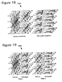
- the DCT can be implemented separably: a vertical 1D 4-point DCT of each column of the 4x4 input data; followed by a horizontal 1D 4-point DCT of the rows (or vice versa). This is depicted as a separable DCT implementation 1800 in Figure 18 .
- the two 1D DCT stages described above can be interleaved between the horizontal and vertical, using the theory of equation (5), as shown as an interleaved DCT implementation 1900 in Figure 19 .
- the first stage is a 2 point Hadamard transform on the "inner” and "outer” input elements.
- the horizontal and vertical stages may be merged into 4 applications of the 2 ⁇ 2 2D Hadamard transform on the 16 input data elements, each transform being applied to a symmetric set of input points.
- the second stage horizontal and vertical steps can be coalesced into a 2 ⁇ 2 Hadamard transform and three 2 ⁇ 2 transforms, two of which are transposes. Observe that the latter three 2 ⁇ 2 transforms are indeed 2D remappings of and defined earlier.
- the reversible scale-free 2D transform 650 ( Figure 6 ) is implemented by so re-arranging the transform operations into an arrangement of the 2 ⁇ 2 Hadamard, and transforms.
- the two stages of this transform 650 are performed as shown in Figures 20 and 21 , respectively.
- Each stage consists of four 2 ⁇ 2 transforms which may be done in any arbitrary sequence, or concurrently, within the stage.
- the stages are reversed in order, and the steps within each stage of transformation use the inverse of the steps in the forward transform process.
- the reversible 2 ⁇ 2 Hadamard transform is its own inverse, in a bit exact or lossless sense. Therefore, the second stage of the inverse Photon transform is merely the first stage of the forward Photon transform, as shown in Figure 20 .
- the first stage 2200 of the inverse Photon transform is depicted in Figure 22 .
- the four steps within this stage (which, as for the forward transform case, may be executed in arbitrary order or concurrently) apply the inverses of , and as defined earlier, and remapped back to a 2D 2 ⁇ 2 space.
- a nontrivial step is an operation of the form (3 ⁇ x + r ) >> k, where x is the operand, r and k are constants determining rounding and bit shift. k is either 2, 3 or 4. Likewise, there are 17 single-place right shifts (i.e. x >> 1) per block. Additions, subtractions and negations are not counted in this overview.
- the YUV 4:2:0 colorspace is used to represent the color of pixels in an image (or video frame).
- a macroblock in the YUV 4:2:0 colorspace is defined as a 16 ⁇ 16 tile of pixels in the luminance (Y) channel, and 8 ⁇ 8 tiles in the chrominance (U and V) channels. These are further divided into 4 ⁇ 4 blocks that are transform coded using the above-described transform 650.
- the 4 ⁇ 4 transform 650 is applied to the DC coefficients of the luminance channels. However, only 2 ⁇ 2 samples of chrominance are available within a macroblock.
- the example codec then applies , which as described earlier is a reversible scale-free 2 ⁇ 2 Hadamard transform, to the DC chrominance values within each macroblock.
- a reversible scale-free 2 ⁇ 2 Hadamard transform to the DC chrominance values within each macroblock.
- the formulations of , and shown earlier as C++ code snippets add varying factors to operands being divided or right bit-shifted. These factors are chosen so as to minimize the bias.
- the bias in the four transform coefficients after the first stage operation of (to an unbiased input) using the C++ code listing 900 in Figure 9 can be shown to be [1 ⁇ 4 -1 ⁇ 4 -1 ⁇ 4 -1 ⁇ 4].
- the second stage application of in the improved 2D transform 650 ( Figure 6 ) operates on the DC values of the first stage, i.e. on coefficients which are already biased to 1 ⁇ 4.
- the result of the second stage operation produces a bias of [3 ⁇ 4 -1 ⁇ 4 -1 ⁇ 4 -1 ⁇ 4]. Since the first coefficient is the DC of DC, it is expected to be large and the relatively high bias of % does not affect coding performance.
- a codec typically, the definition of a codec is restricted to a definition of the bitstream decoder.
- An exception to this rule is made for lossless codecs, since the encoder and decoder must be in perfect match for the input data to be reconstructed with no loss. In the case of a lossy-to-lossless codec, it is defined on both the encoder and decoder sides.
- some shortcuts or enhancements may be possible that can give better performance (in terms of rate-distortion, or computational cycle count) than the baseline performance as defined in the codec specification.
- One means of improving encoder performance relates to transform coefficient bias. It is possible to reduce the effect of bias in some embodiments of the encoder 600/decoder 700 by carrying out the following procedure for each 4 ⁇ 4 block:
- the above described codec with improved reversible, scale-free 2D transform can be performed on any of a variety of devices in which digital media signal processing is performed, including among other examples, computers; image and video recording, transmission and receiving equipment; portable video players; video conferencing; and etc.
- the digital media coding techniques can be implemented in hardware circuitry, as well as in digital.media processing software executing within a computer or other computing environment, such as shown in Figure 24 .
- FIG. 24 illustrates a generalized example of a suitable computing environment (2400) in which described embodiments may be implemented.
- the computing environment (2400) is not intended to suggest any limitation as to scope of use or functionality of the invention, as the present invention may be implemented in diverse general-purpose or special-purpose computing environments.
- the computing environment (2400) includes at least one processing unit (2410) and memory (2420).
- the processing unit (2410) executes computer-executable instructions and may be a real or a virtual processor. In a multi-processing system, multiple processing units execute computer-executable instructions to increase processing power.
- the memory (2420) may be volatile memory (e.g., registers, cache, RAM), non-volatile memory (e.g., ROM, EEPROM, flash memory, etc.), or some combination of the two.
- the memory (2420) stores software (2480) implementing the described encoder/decoder and transforms.
- a computing environment may have additional features.
- the computing environment (2400) includes storage (2440), one or more input devices (2450), one or more output devices (2460), and one or more communication connections (2470).
- An interconnection mechanism such as a bus, controller, or network interconnects the components of the computing environment (2400).
- operating system software provides an operating environment for other software executing in the computing environment (2400), and coordinates activities of the components of the computing environment (2400).
- the storage (2440) may be removable or non-removable, and includes magnetic disks, magnetic tapes or cassettes, CD-ROMs, CD-RWs, DVDs, or any other medium which can be used to store information and which can be accessed within the computing environment (2400).
- the storage (2440) stores instructions for the software (2480) implementing the codec with improved SDLT.
- the input device(s) (2450) may be a touch input device such as a keyboard, mouse, pen, or trackball, a voice input device, a scanning device, or another device that provides input to the computing environment (2400).
- the input device(s) (2450) may be a sound card or similar device that accepts audio input in analog or digital form, or a CD-ROM reader that provides audio samples to the computing environment.
- the output device(s) (2460) may be a display, printer, speaker, CD-writer, or another device that provides output from the computing environment (2400).
- the communication connection(s) (2470) enable communication over a communication medium to another computing entity.
- the communication medium conveys information such as computer-executable instructions, compressed audio or video information, or other data in a modulated data signal.
- a modulated data signal is a signal that has one or more of its characteristics set or changed in such a manner as to encode information in the signal.
- communication media include wired or wireless techniques implemented with an electrical, optical, RF, infrared, acoustic, or other carrier.
- Computer-readable media are any available media that can be accessed within a computing environment.
- Computer-readable media include memory (2420), storage (2440), communication media, and combinations of any of the above.
- the digital media processing techniques herein can be described in the general context of computer-executable instructions, such as those included in program modules, being executed in a computing environment on a target real or virtual processor.
- program modules include routines, programs, libraries, objects, classes, components, data structures, etc. that perform particular tasks or implement particular abstract data types.
- the functionality of the program modules may be combined or split between program modules as desired in various embodiments.
- Computer-executable instructions for program modules may be executed within a local or distributed computing environment.
Landscapes
- Engineering & Computer Science (AREA)
- Physics & Mathematics (AREA)
- General Physics & Mathematics (AREA)
- Mathematical Physics (AREA)
- Theoretical Computer Science (AREA)
- Data Mining & Analysis (AREA)
- Multimedia (AREA)
- Pure & Applied Mathematics (AREA)
- Mathematical Analysis (AREA)
- Mathematical Optimization (AREA)
- Computational Mathematics (AREA)
- Signal Processing (AREA)
- Algebra (AREA)
- General Engineering & Computer Science (AREA)
- Discrete Mathematics (AREA)
- Software Systems (AREA)
- Databases & Information Systems (AREA)
- Compression, Expansion, Code Conversion, And Decoders (AREA)
- Compression Or Coding Systems Of Tv Signals (AREA)
- Compression Of Band Width Or Redundancy In Fax (AREA)
- Complex Calculations (AREA)
Description
- The invention relates generally to block transform-based digital media (e.g., video and image) compression.
- Transform coding is a compression technique used in many audio, image and video compression systems. Uncompressed digital image and video is typically represented or captured as samples of picture elements or colors at locations in an image or video frame arranged in a two-dimensional (2D) grid. This is referred to as a spatial-domain representation of the image or video. For example, a typical format for images consists of a stream of 24-bit color picture element samples arranged as a grid. Each sample is a number representing color components at a pixel location in the grid within a color space, such as RGB, or YIQ, among others. Various image and video systems may use various different color, spatial and time resolutions of sampling. Similarly, digital audio is typically represented as time-sampled audio signal stream. For example, a typical audio format consists of a stream of 16-bit amplitude samples of an audio signal taken at regular time intervals.
- Uncompressed digital audio, image and video signals can consume considerable storage and transmission capacity. Transform coding reduces the size of digital audio, images and video by transforming the spatial-domain representation of the signal into a frequency-domain (or other like transform domain) representation, and then reducing resolution of certain generally less perceptible frequency components of the transform-domain representation. This generally produces much less perceptible degradation of the digital signal compared to reducing color or spatial resolution of images or video in the spatial domain, or of audio in the time domain.
- More specifically, a typical block transform-based
codec 100 shown inFigure 1 divides the uncompressed digital image's pixels into fixed-size two dimensional blocks (X1, ... Xn), each block possibly overlapping with other blocks. A linear transform 120-121 that does spatial-frequency analysis is applied to each block, which converts the spaced samples within the block to a set of frequency (or transform) coefficients generally representing the strength of the digital signal in corresponding frequency bands over the block interval. For compression, the transform coefficients may be selectively quantized 130 (i.e., reduced in resolution, such as by dropping least significant bits of the coefficient values or otherwise mapping values in a higher resolution number set to a lower resolution), and also entropy or variable-length coded 130 into a compressed data stream. At decoding, the transform coefficients will inversely transform 170-171 to nearly reconstruct the original color/spatial sampled image/video signal (reconstructed blocks X̂1, ... X̂n). - The block transform 120-121 can be defined as a mathematical operation on a vector x of size N. Most often, the operation is a linear multiplication, producing the transform domain output y = M x, M being the transform matrix. When the input data is arbitrarily long, it is segmented into N sized vectors and a block transform is applied to each segment. For the purpose of data compression, reversible block transforms are chosen. In other words, the matrix Mis invertible. In multiple dimensions (e.g., for image and video), block transforms are typically implemented as separable operations. The matrix multiplication is applied separably along each dimension of the data (i.e., both rows and columns).
- For compression, the transform coefficients (components of vector y) may be selectively quantized (i.e., reduced in resolution, such as by dropping least significant bits of the coefficient values or otherwise mapping values in a higher resolution number set to a lower resolution), and also entropy or variable-length coded into a compressed data stream.
- At decoding in the
decoder 150, the inverse of these operations (dequantization/entropy decoding 160 and inverse block transform 170-171) are applied on thedecoder 150 side, as show inFig. 1 . While reconstructing the data, the inverse matrix M -1 (inverse transform 170-171) is applied as a multiplier to the transform domain data. When applied to the transform domain data, the inverse transform nearly reconstructs the original time-domain or spatial-domain digital media. - In many block transform-based coding applications, the transform is desirably reversible to support both lossy and lossless compression depending on the quantization factor. With no quantization (generally represented as a quantization factor of 1) for example, a codec utilizing a reversible transform can exactly reproduce the input data at decoding. However, the requirement of reversibility in these applications constrains the choice of transforms upon which the codec can be designed.
- Many image and video compression systems, such as MPEG and Windows Media, among others, utilize transforms based on the Discrete Cosine Transform (DCT). The DCT is known to have favorable energy compaction properties that result in near-optimal data compression. In these compression systems, the inverse DCT (IDCT) is employed in the reconstruction loops in both the encoder and the decoder of the compression system for reconstructing individual image blocks. The DCT is described by N. Ahmed, T. Natarajan, and K.R. Rao, "Discrete Cosine Transform," IEEE Transactions on Computers, C-23 (January 1974), pp. 90-93. An exemplary implementation of the IDCT is described in "IEEE Standard Specification for the Implementations of 8x8 Inverse Discrete Cosine Transform," IEEE Std. 1180-1990, December 6, 1990.
- Conventional data transforms used to implement reversible 2D data compressor have generally suffered one or more of the following primary disadvantages,
- 1. Unequal norms between transform coefficients, requiring complicated entropy coding schemes;
- 2. Poor approximations to optimal transforms, such as the DCT; and
- 3. High computational complexity.
- A separable 2D transform is typically implemented by performing 1D transforms on the rows of the data, followed by 1D transform on its columns of data (or vice versa). See, A. K. Jain, Fundamentals of Digital Image Processing, Prentice Hall, 1989. In matrix notation, let T represent the transform matrix and X be the 2D data. The separable 2D transform with T is defined by Y in the following equation.

- Indeed, the row-wise and column-wise transforms may be distinct. For instance, the data matrix could be non-square (say of size 4x8), or the row-wise and column-wise transforms could be the DCT and discrete sine transform (DST) respectively. In this case, the pre and post multipliers are different (say T 1 and T 2) and the transform Y is given by

- For example,
Figure 2 shows a 2D 4x4 DCT implemented in two stages. In the first stage, the columns of the data matrix are transformed using a 4point 1D DCT. In the second stage, 4point 1D DCTs are applied along the rows. With infinite arithmetic accuracy, this ordering may be switched with no change in the output. - The 4
point 1D DCT can be implemented as a sequence of multiplication and addition operations on the 4 input data values, as represented in the signal flow graph shown inFigure 3 . The values c and s in this diagram are respectively cosine and sine of π/8. The separable transform approach works well for a lossy codec. Lossless codecs are more challenging to realize. Even with unit quantization, the separable 2D DCT described above in conjunction with its separable inverse DCT or IDCT is not guaranteed to produce a bit exact match to the original input. This is because the divisors inFigure 3 give rise to rounding errors that may not cancel out between the encoder and decoder. - In order to achieve lossless compression with a block transform-based codec, it is necessary to replace the above-described
4x4 2D DCT with a lossless transform. A separable transform may be used only if each 1D transform is lossless or reversible. Although multiple choices exist for reversible 1D transforms, those based on "lifting" are by far the most desirable. Lifting is a process of performing a matrix-vector multiplication using successive "shears." A shear is defined as a multiplication of the operand vector with a matrix which is an identity matrix plus one non-zero off-diagonal element. Sign inversion of one or more vector coefficients may occur anywhere during this process, without loss of generality. - Lifting has been implemented through ladder or lattice filter structures in the past. Lifting or successive shear based techniques have been used in graphics. See, A. Tanaka, M. Kameyama, S. Kazama, and O. Watanabe, "A rotation method for raster image using skew transformation," Proc IEEE Conf on Computer Vision and Pattern Recognition, pages 272-277, June 1986; and A. W. Paeth, "A fast algorithm for general raster rotation," Proceedings of Graphics Interface '86, pages 77-81, May 1986. In fact, it can be argued that Gauss-Jordan elimination is a manifestation of lifting.
- One simple 2 point operation is the Hadamard transform, given by the transform matrix

Figure 4 . The second approach is to allow the scales to differ between the two transform coefficients, as shown inFigure 5 . - Lifting is not without its problems. In the first Hadamard transform approach shown in
Figure 4 , the two transform coefficients are normalized. This is desirable for realizing multi-stage transforms, such as the 4 or 8 point DCT. However, this implementation suffers from two major drawbacks - first, each 2 point Hadamard transform requires three non-trivial (i.e., computationally expensive) lifting steps, and second, rounding errors in the lifting steps cause low pass energy to "leak" into the high frequency term leading to reduced compression efficiency. In this first approach, using the approximation

- The second approach (
Figure 5 ) uses trivial lifting steps. However, the low pass term is scaled up by a factor of

- In summary, the problems with lifting based lossless transforms are:
- 1. Possible unequal scaling between transform coefficients, making for more complex entropy coding mechanisms.
- 2. Poor approximations to desired transform basis functions that may cause undesirable effects such as the leakage of DC into AC bands.
- 3. Potentially high computational complexity, especially so if the lifting based implementation is designed to well approximate the desired transform.
-
US 2004/047512 A1 describes an approach for video encoding an decoding. It uses a 2-dimensional transform separable into two 1-dimensional transforms. The video is encoded by performing a first 1-dimensional transform of the array, transposing the resulting array, and performing a second 1-dimensional transform of the array resulting from the transpose. - The document "New invertible integer color transforms based on lifting steps and coding of a 4:4:4 video" by Pankaj Topiwala et al., Joint Video Team (JVT) of ISO/IEC MPEG & ITU-T VCEG (ISO/IEC JTC1/SC29/WG11 and ITU-T SG16 Q6), describes an invertible integer color transform, which has a lifting-based implementation.
- In Track D. Tran et al.: "Lapped transform via time-domain pre- and post-filtering", IEEE Transactions on Signal Processing, 51 (6), 2003, a general framework for constructing lapped transforms with symmetric basis functions as described, wherein simple time-domain pre- and post-processing modules are added onto existing block DCT-based infrastructures.
- The above problems are solved by a method, an encoder and a decoder as defined in the independent claims. Preferred embodiments of the invention are defined in the corresponding dependent claims.
- A digital media encoder/decoder system is based on a separable 2D block transform which has various implementations described herein that address the above-indicated problems and drawbacks of prior art transforms. In particular, a described implementation of the pair of a separable 2D transform and its inverse has a sequence of lifting steps arranged for reduced computational complexity (i.e., reducing a number of non-trivial operations). This transform pair has energy compaction properties similar to the DCT, and is also lossless and scale-free. The term "lossless" means that the original integer input to the transform can be recovered without error by the inverse transform, from its integer transform coefficients, assuming no quantization. "Scale-free" refers to the transform pair's basis functions being equally scaled, which also means that the resulting transform matrix is orthogonal.
- One described implementation of this transform pair is as a 4x4 transform, but can be extended to other sizes as well (e.g., 8x8, etc.). Furthermore, cascades of the transform pair may be used to realize hierarchical pyramids and larger transforms. For instance, one described implementation uses a two level cascade of the transform. In the second transform stage, the transform is applied to the 16 DC coefficients generated within a macroblock. Since the transform is similar to the DCT, it can be used to realize a lossless-to-lossy digital media codec (i.e., a codec whose quantization parameter can be varied from a lossless setting to lossy settings) with superior rate-distortion performance and compression efficiency.
- Additional features and advantages of the invention will be made apparent from the following detailed description of embodiments that proceeds with reference to the accompanying drawings.
-
-
Figure 1 is a block diagram of a conventional block transform-based codec in the prior art. -
Figure 2 is a block diagram of a 2D 4x4 DCT implemented in two stages, also in the prior art. -
Figure 3 is a signal flow graph of a 1D 4x4 DCT, also in the prior art. -
Figure 4 is a signal flow graph of a normalized 2-point Hadamard transform using lifting, also in the prior art. -
Figure 5 is a signal flow graph of a trivial 2-point Hadamard transform, also in the prior art. -
Figure 6 is a flow diagram of an encoder based on an improved reversible 2D transform. -
Figure 7 is a flow diagram of an decoder based on the improved reversible 2D transform. -
Figure 8 is a signal flow graph of a normalized lifting-based implementation of the reversible 2x2 Hadamard transform. -
Figure 9 is a program listing in the C programming language for realizing the normalized reversible 2x2 Hadamard transform ofFigure 8 . -
Figure 10 is a signal flow graph of an inverse of the normalized reversible 2x2 Hadamard transform ofFigure 8 . -
Figure 11 is a signal flow graph of a normalized lifting-based implementation of thetransform.
-
Figure 12 is a program listing in the C programming language for realizing the normalizedtransform ofFigure 11 . -
Figure 13 is a signal flow graph of a normalized lifting-based version of the inverse of thetransform ofFigure 11 . -
Figure 14 is a signal flow graph of a normalized lifting-based implementation of thetransform.
-
Figure 15 is a program listing in the C programming language for realizing the normalizedtransform ofFigure 14 . -
Figure 16 is a signal flow graph of a normalized lifting-based version of the inverse of thetransform ofFigure 14 . -
Figure 17 is a diagram illustrating the ordering of 2x2 data in the depictions herein of transforms and inverse transform operations. -
Figure 18 is a signal flow graph illustrating a 2D DCT implemented separably as a 1D vertical DCT and a 1D horizontal DCT applied to columns and rows, respectively, of a 4x4 data input. -
Figure 19 is a signal flow graph illustrating the reversible, scale-free 2D transform implemented by interleaving horizontal and vertical transform operations in two stages. -
Figure 20 is a diagram illustrating the points of a 4x4 data block to which the 2x2 Hadamard transform ofFigure 8 is applied in a first stage of an implementation of the improved, reversible 2D transform in the encoder ofFigure 6 . -
Figure 21 is a diagram illustrating the points of the 4x4 data block to which the 2x2 Hadamard transform ofFigure 8 , thetransform ofFigure 11 , and thetransform ofFigure 14 are applied in a second stage of the implementation of the improved, reversible 2D transform in the encoder ofFigure 6 . -
Figure 22 is a diagram illustrating the points of the 4x4 transform coefficients block to which the 2x2 Hadamard transform ofFigure 8 , thetransform ofFigure 11 , and thetransform ofFigure 14 are applied in a first stage of the implementation of the inverse 2D transform in the decoder ofFigure 7 . -
Figure 23 is a diagram illustrating the ordering of transform coefficients for the forward and inverse 2D transform in the encoder ofFigure 6 and decoder ofFigure 7 . -
Figure 24 is a block diagram of a suitable computing environment for implementing the block transform-based codec with improved spatial-domain lapped transform ofFigures 6 and7 . -
Figure 25 is a signal flow graph of a structure for the normalized lifting-based implementation of the reversible 2x2 transforms shown inFigures 11 and14 . - The following description relates to a digital media compression system or codec, which utilizes an improved, reversible scale-free 2D transform. For purposes of illustration, an embodiment of a compression system incorporating the improved transform is an image or video compression system. Alternatively, the improved transform also can be incorporated into compression systems or codecs for other 2D data. The transform does not require that the digital media compression system encodes the compressed digital media data in a particular coding format.
-
Figures 6 and7 are a generalized diagram of the processes employed in a representative 2-dimensional (2D)data encoder 600 anddecoder 700 based on the improved, reversible scale-free 2D transform 650 detailed below. The diagrams present a generalized or simplified illustration of the use and application of this transform in a compression system incorporating the 2D data encoder and decoder. In alternative encoders based on this transform, additional or fewer processes than those illustrated in this representative encoder and decoder can be used for the 2D data compression. For example, some encoders/decoders may also include color conversion, color formats, scalable coding, lossless coding, macroblock modes, etc. The improved 2D transform permits the compression system (encoder and decoder) to provide lossless and/or lossy compression of the 2D data, depending on the quantization which may be based on a quantization parameter varying from lossless to lossy. - The
2D data encoder 600 produces acompressed bitstream 620 that is a more compact representation (for typical input) of2D data 610 presented as input to the encoder. For example, the 2D data input can be an image, a frame of a video sequence, or other data having two dimensions. The 2Ddata encoder tiles 630 the input data into macroblocks, which are 16×16 pixels in size in this representative encoder. The 2D data encoder further tiles each macroblock into 4x4 blocks 632. A "forward overlap"operator 640 is applied to each edge between blocks, after which each 4×4 block is transformed using the reversible scale-free transform 650. Subsequently, the DC coefficient 660 of each 4x4 transform block is subject to a similar processing chain (tiling, forward overlap, followed by 4x4 block transform). The resulting DC transform coefficients and the AC transform coefficients are quantized 670, entropy coded 680 and packetized 690. - The decoder performs the reverse process. On the decoder side, the transform coefficient bits are extracted 710 from their respective packets, from which the coefficients are themselves decoded 720 and
dequantized 730. The DC coefficients 740. are regenerated by applying an inverse transform, and the plane of DC coefficients is "inverse overlapped" using a suitable smoothing operator applied across the DC block edges. Subsequently, the entire data is regenerated by applying the 4x4inverse transform 750 to the DC coefficients, and theAC coefficients 742 decoded from the bitstream. Finally, the block edges in the resulting image planes are inverse overlap filtered 760. This produces a reconstructed 2D data output. - As described by, e.g., A. K. Jain, Fundamentals of Digital Image Processing, Prentice Hall, 1989, a separable 2D transform can be implemented as a 1D transform operating on the data ordered in 1D, producing a likewise ordered vector result The equivalent transform matrix is generated by the Kronecker product of the pre- and post-multipliers used in the separable case. If x and y denote the data and transform vectors reordered from their 2D representation in (2), their relationship is given by the following


- Although the separable implementation of a 2D transform shown in equation (2) is computationally more efficient (in an asymptotic sense) than in equation (3), there are certain cases where the latter representation leads to desirable properties. For instance, an implementation based on equation (3) has lower latency than in equation (2), due to a single stage matrix multiply (which is an operation supported natively on several digital signal processors (DSPs)). For the improved, reversible scale-free transform described herein, the 1D representation of 2x2 steps leads to a scale-free reversible structure.
- Moreover, a separable 2D transform can be implemented as a cascade of simpler 1D transforms. Assume that the transform matrices T 1 and T 2 can be decomposed as follows

- Associativity of the matrix multiply operation can be used to reorder the 2D transform (2) as follows


- Transforms such as the DCT can be formulated as a cascade of elementary 2 point rotation operations. The 2D DCT can be formulated using the structure of (6) to possess certain desirable properties, which will be described in detail further ahead.
- The 2D Hadamard transform, implemented as a 1D operation is generated by the Kronecker product,

- Interestingly, it is possible to realize a scale-free reversible transform corresponding to equation (7), using only trivial lifting steps. An implementation of this form is shown as the
signal flow graph 800 inFigure 8 . Corresponding C++ code eliminating some redundant operations is shown inFigure 9 . In thiscode listing 900, "swap(x,y)" is a function that exchanges the values of its arguments. - From the foregoing, it can be seen that the normalized reversible 2D Hadamard transform can be formulated using only trivial lifting steps, although this is not possible for the arguably "simpler" 1D Hadamard case! Although the transform matrix itself is involutory (i.e.,is its own inverse), a lossless reconstruction requires that the lifting steps be carefully reversed so as to precisely reproduce any rounding effects. The

inverse 1000 of thestructure 800 inFigure 8 is presented inFigure 10 - thestructure 1000 is identical to the forward transform in this case. Note that the transform coefficients B and C are permuted in the signal flow graphs. - The reversible, scale-
free 2D transform 650 in theencoder 600 ofFigure 6 uses an approximation to the 4x4 DCT. The following description demonstrates the entire transform process of thetransform 650 can be realized as the cascade of three elementary 2×2 transform operations, which are the 2×2 Hadamard transform, and the following:


 is used to denote the 2×2 Hadamard transform implemented in 1D, without any ambiguity. Next, we look at the lifting implementation of
 and.
and.
B. Implementation of - A scale-free, lifting based implementation of the
transform 1100 is shown as a signal-flow graph inFigure 11 , and in a C++code program listing 1200 inFigure 12 . It can be seen that the first and last lifting stages are identical to the Hadamard transform case. Besides trivial shears, two non-trivial lifting rotations are applied in the intermediate stages. Each non-trivial rotation is implemented in three steps, with a multiply by 3 and a bit shift by 3 or 4 bits. Therefore,can be realized in a reversible, scale-free manner by using 6 non-trivial lifting steps. - The resulting 1D transform matrixis shown below (12), which is in close conformance with the original formulation ofin (10). It can be seen that the second and fourth rows of the resulting transform matrix sum to zero, which means that there is no leakage of DC into the AC bands. This desirable property is achieved although the required 2D rotations are merely approximated in the structure.


- Although the transform matrixis involutory (i.e., is its own inverse), rounding errors do not cancel out in two successive applications of the signal flow graph or code. The lossless inverse ofis derived by reversing the lifting steps, either in the signal flow graph or in the C++ code, to replicate forward transform side rounding errors. The signal flow graph of the
inverse 1300 ofis shown inFigure 13 - code can be derived likewise.
C. Implementation of - The
transform 1400 is composed of two rotations, neither of which is a Hadamard transform. Interestingly,can be realized with fewer non-trivial lifting steps than. This is due to the symmetry properties of the Kronecker product of TR with itself. The signal flow graph of thetransform 1400 andprogram listing 1500 of its C++ code realization are shown inFigures 14 and 15 , respectively. - It can be seen that only one non-trivial rotation, implemented by means of three non-trivial lifting steps is required to realize. This rotation corresponds to the scale-free 1D 2-point Hadamard transform.


- As with the other transforms considered here,as represented in equation (13) is involutory, though not a bit exact inverse of itself. The
lossless inverse 1600 ofis obtained by reversing the signal flow graph used for the forward transform, as shown inFigure 16 . - In the depictions herein of the reversible, scale-free 2D transform using these three reversible scale-free transforms, the following points apply. First, the ordering 1700 of the 2x2 data resulting in the above signal flow graphs and C++ code is as shown in
Figure 17 . The spatial domain points are shown on the left, and corresponding frequency domain points on the right Color coding using four gray levels to indicate the four data points is introduced here, to facilitate the reversible, scale-free 2D transform description that follows. - Often, 2 point transforms or rotations are defined as the following operation


- These two forms are essentially identical, since they differ only in sign of the second transform coefficient. The latter representation (15) is used here, although the entire derivation in this document is equally applicable to the former form (14).
- The structure of the basic 2x2 transforms,,
 and, defined above are constructed by noting each two-point transform is a rotation. Further, the Kronecker product of two 2-point rotations is given as follows:
- We then define an operator H as follows:

- The following factorization holds:

- Based on this, a Kronecker product of the type T can be implemented as a cascade of 3 stages:
- A. A double butterfly operation defined by H using lifting steps.
- B. 2 point rotations between the first pair of components, and between the second pair of components, and
- C. The reverse of the double butterfly performed in step a.
- For the special case, an even simpler decomposition exists, which is shown as the
signal flow graph 800 inFigure 8 and described above. For the other cases (e.g.,and ), the resulting structure can be generalized as theflow graph 2500 shown inFigure 25 . - Looking at the three signal flow graphs of the transforms described above (and also their inverses), observe a fundamental similarity in their structure. The first stage of the transform is a lifting operation between the a-d and b-c coefficients. Likewise, the last stage is the inverse lifting process (discounting sign and coefficient exchanges). Correspondingly, the first stage of the inverse transform is a lifting operation between A and D, and also between B and C, with the reverse operation in the last stage. The lifting steps between the diagonal elements is a distinguishing feature of the combined
2D 2×2 transform presented here. - The next section discusses the construction of a lossless, scale-free transform, which approximates the 4×4 DCT/IDCT. Although an exemplary embodiment of the transform is presented in this detailed technical discussion, the same procedure, with the additional definition of other 2×2 elementary reversible lifting based transforms, can be used to generate higher dimensional reversible transform embodiments with desirable properties.
- The 4-point DCT can be reduced to a sequence of four butterfly operations as shown in the signal flow graph of
Figure 3 . The first stage consists of two butterflies performing 2-point Hadamard operations on the input data (i.e., one 2-point Hadamard ofinput data indices input indices 1 and 2). The second stage comprises a 2 point Hadamard operation on the low pass results of the first stage to generate the even frequency components (indices 0 and 2), and a 2 point rotation by π/8 to generate the odd frequency components (indices 1 and 3). - In two dimensions, the DCT can be implemented separably: a vertical 1D 4-point DCT of each column of the 4x4 input data; followed by a horizontal 1D 4-point DCT of the rows (or vice versa). This is depicted as a
separable DCT implementation 1800 inFigure 18 . Alternatively, the two 1D DCT stages described above can be interleaved between the horizontal and vertical, using the theory of equation (5), as shown as an interleavedDCT implementation 1900 inFigure 19 . - Moreover, when the above approach is followed, the corresponding horizontal and vertical stages can be further combined. For instance, the first stage is a 2 point Hadamard transform on the "inner" and "outer" input elements. The horizontal and vertical stages may be merged into 4 applications of the 2×2 2D Hadamard transform on the 16 input data elements, each transform being applied to a symmetric set of input points. Likewise, the second stage horizontal and vertical steps can be coalesced into a 2×2 Hadamard transform and three 2×2 transforms, two of which are transposes. Observe that the latter three 2×2 transforms are indeed 2D remappings ofanddefined earlier.
- More particularly, the reversible scale-free 2D transform 650 (
Figure 6 ) is implemented by so re-arranging the transform operations into an arrangement of the 2×2 Hadamard,andtransforms. The two stages of thistransform 650 are performed as shown inFigures 20 and 21 , respectively. Each stage consists of four 2×2 transforms which may be done in any arbitrary sequence, or concurrently, within the stage. - For the inverse 2D transform 750 (
Figure 7 ), the stages are reversed in order, and the steps within each stage of transformation use the inverse of the steps in the forward transform process. As noted earlier, the reversible 2×2 Hadamard transformis its own inverse, in a bit exact or lossless sense. Therefore, the second stage of the inverse Photon transform is merely the first stage of the forward Photon transform, as shown inFigure 20 . Thefirst stage 2200 of the inverse Photon transform is depicted inFigure 22 . The four steps within this stage (which, as for the forward transform case, may be executed in arbitrary order or concurrently) apply the inverses of,andas defined earlier, and remapped back to a2D 2×2 space. - Upon following the steps of the forward improved 2D transform shown in
Figures 20 and 21 , the resulting transform coefficients are ordered as shown inFigure 23 . Thesame ordering 2300 is assumed for the coefficients being inverse transformed using steps inFigures 22 and20 , in that order. - The above described improved implementation of the forward 2D transform 650 consists of five applications of, two applications ofand one application ofto each 4×4 block. The same number of applications of these transforms are involved in the implementation of the
inverse 2D transform 750. Accordingly, the total number of nontrivial lifting steps is 5×0+2×6+1×3 = 15 for each block, to realize the lossless forward or inverse 2D transform. This is about 1 nontrivial step per pixel. A nontrivial step is an operation of the form (3 × x + r) >> k, where x is the operand, r and k are constants determining rounding and bit shift. k is either 2, 3 or 4. Likewise, there are 17 single-place right shifts (i.e. x >> 1) per block. Additions, subtractions and negations are not counted in this overview. - In comparison, consider the
separable implementation 1800 of the 2D DCT illustrated inFigure 18 . Assume that each 4 point DCT is implemented using three 2 point normalized Hadamard operations as shown inFigure 3 , and the rotation by π/8 is implemented using three nontrivial lifting steps. The total number of nontrivial lifting operations per 4×4 block for either the forward or the inverse transform is 2×4×3 = 24. The total number of single-place right shifts is also 24. These numbers are about 50% higher than the improved forward transform 650 andinverse transform 750 implementations, not counting the fact that the resulting transform produces basis functions with norms in the range ¼ through 2 (or through 4 if irrational range basis functions are avoided). In contrast, all basis functions of theimproved transform 650 are unit norm. - In one example implementation of the encoder 600 (
Figure 6 ) and decoder 700 (Figure 7 ), the YUV 4:2:0 colorspace is used to represent the color of pixels in an image (or video frame). In this example codec, a macroblock in the YUV 4:2:0 colorspace is defined as a 16×16 tile of pixels in the luminance (Y) channel, and 8×8 tiles in the chrominance (U and V) channels. These are further divided into 4×4 blocks that are transform coded using the above-describedtransform 650. The 4×4transform 650 is applied to the DC coefficients of the luminance channels. However, only 2×2 samples of chrominance are available within a macroblock. The example codec then applies, which as described earlier is a reversible scale-free 2×2 Hadamard transform, to the DC chrominance values within each macroblock. Thus, the macroblock structure of the example codec format is preserved, and no additional transforms need to be introduced in the codec for handling the 4:2:0 format. - Rounding errors are introduced in the lifting steps of the,andtransforms that involve a right bit-shift. These rounding errors have a known bias, and can build up over the course of the transform. For instance, it is known that a step of the form x+=(y>>1) leads to a bias of -¼ in the value of x, compared to its mathematical equivalent x=x+y/2. This is because (y>>1) is a division by 2 rounded down, which is exact if y is even, and off by ½ if y is odd. Probabilistically therefore, it is biased by -¼. Rounding errors are unavoidable in integer-to-integer transforms involving lifting, but it is desirable to minimize the bias in the overall system.
- The formulations of,andshown earlier as C++ code snippets add varying factors to operands being divided or right bit-shifted. These factors are chosen so as to minimize the bias. In particular, the bias in the four transform coefficients after the first stage operation of(to an unbiased input) using the C++ code listing 900 in
Figure 9 can be shown to be [¼ -¼ -¼ -¼]. The second stage application ofin the improved 2D transform 650 (Figure 6 ) operates on the DC values of the first stage, i.e. on coefficients which are already biased to ¼. The result of the second stage operation produces a bias of [¾ -¼ -¼ -¼]. Since the first coefficient is the DC of DC, it is expected to be large and the relatively high bias of % does not affect coding performance. - The nontrivial lifting steps inandprovide freedom to choose rounding factors for minimizing transform bias. The C++ code listing 1500 (
Figure 15 ) forshows that sometimes off-center rounding rules (such as a+=(3b+5)>>3) lead to smaller overall bias, especially when the input data is itself biased. For the improved 2D transform stepsand, all inputs are biased to -¼. - Typically, the definition of a codec is restricted to a definition of the bitstream decoder. An exception to this rule is made for lossless codecs, since the encoder and decoder must be in perfect match for the input data to be reconstructed with no loss. In the case of a lossy-to-lossless codec, it is defined on both the encoder and decoder sides. However, when the encoder is operated in a purely lossy mode, some shortcuts or enhancements may be possible that can give better performance (in terms of rate-distortion, or computational cycle count) than the baseline performance as defined in the codec specification.
- One means of improving encoder performance relates to transform coefficient bias. It is possible to reduce the effect of bias in some embodiments of the
encoder 600/decoder 700 by carrying out the following procedure for each 4×4 block: - 1. Scale up the 4×4 block by multiplying by m = 2 k (typically m = 4 works well).
- 2. Perform the improved 2D transform 650 on the block.
- 3. Quantize the block using a quantizer which is m times the original desired quantization parameter (for instance, use a quantization factor (QP) of 32 if the desired QP is 8 and m = 4 in step 1).
- There is no change on the
decoder 700 side, yet better PSNR numbers are possible at the same bitrate. Of course, this does not work for lossless encoding. - The above described codec with improved reversible, scale-free 2D transform can be performed on any of a variety of devices in which digital media signal processing is performed, including among other examples, computers; image and video recording, transmission and receiving equipment; portable video players; video conferencing; and etc. The digital media coding techniques can be implemented in hardware circuitry, as well as in digital.media processing software executing within a computer or other computing environment, such as shown in
Figure 24 . -
Figure 24 illustrates a generalized example of a suitable computing environment (2400) in which described embodiments may be implemented. The computing environment (2400) is not intended to suggest any limitation as to scope of use or functionality of the invention, as the present invention may be implemented in diverse general-purpose or special-purpose computing environments. - With reference to
Figure 24 , the computing environment (2400) includes at least one processing unit (2410) and memory (2420). InFigure 24 , this most basic configuration (2430) is included within a dashed line. The processing unit (2410) executes computer-executable instructions and may be a real or a virtual processor. In a multi-processing system, multiple processing units execute computer-executable instructions to increase processing power. The memory (2420) may be volatile memory (e.g., registers, cache, RAM), non-volatile memory (e.g., ROM, EEPROM, flash memory, etc.), or some combination of the two. The memory (2420) stores software (2480) implementing the described encoder/decoder and transforms. - A computing environment may have additional features. For example, the computing environment (2400) includes storage (2440), one or more input devices (2450), one or more output devices (2460), and one or more communication connections (2470). An interconnection mechanism (not shown) such as a bus, controller, or network interconnects the components of the computing environment (2400). Typically, operating system software (not shown) provides an operating environment for other software executing in the computing environment (2400), and coordinates activities of the components of the computing environment (2400).
- The storage (2440) may be removable or non-removable, and includes magnetic disks, magnetic tapes or cassettes, CD-ROMs, CD-RWs, DVDs, or any other medium which can be used to store information and which can be accessed within the computing environment (2400). The storage (2440) stores instructions for the software (2480) implementing the codec with improved SDLT.
- The input device(s) (2450) may be a touch input device such as a keyboard, mouse, pen, or trackball, a voice input device, a scanning device, or another device that provides input to the computing environment (2400). For audio, the input device(s) (2450) may be a sound card or similar device that accepts audio input in analog or digital form, or a CD-ROM reader that provides audio samples to the computing environment. The output device(s) (2460) may be a display, printer, speaker, CD-writer, or another device that provides output from the computing environment (2400).
- The communication connection(s) (2470) enable communication over a communication medium to another computing entity. The communication medium conveys information such as computer-executable instructions, compressed audio or video information, or other data in a modulated data signal. A modulated data signal is a signal that has one or more of its characteristics set or changed in such a manner as to encode information in the signal. By way of example, and not limitation, communication media include wired or wireless techniques implemented with an electrical, optical, RF, infrared, acoustic, or other carrier.
- The digital media processing techniques herein can be described in the general context of computer-readable media. Computer-readable media are any available media that can be accessed within a computing environment. By way of example, and not limitation, with the computing environment (2400), computer-readable media include memory (2420), storage (2440), communication media, and combinations of any of the above.
- The digital media processing techniques herein can be described in the general context of computer-executable instructions, such as those included in program modules, being executed in a computing environment on a target real or virtual processor. Generally, program modules include routines, programs, libraries, objects, classes, components, data structures, etc. that perform particular tasks or implement particular abstract data types. The functionality of the program modules may be combined or split between program modules as desired in various embodiments. Computer-executable instructions for program modules may be executed within a local or distributed computing environment.
- For the sake of presentation, the detailed description uses terms like "determine," "generate," "adjust," and "apply" to describe computer operations in a computing environment. These terms are high-level abstractions for operations performed by a computer, and should not be confused with acts performed by a human being. The actual computer operations corresponding to these terms vary depending on implementation.
- In view of the many possible embodiments to which the principles of our invention may be applied, we claim as our invention all such embodiments as may come within the scope of the following claims and equivalents thereto.
Claims (21)
- A method of performing (1900) a compression of 2-dimensional digital media data, the method comprising:
receiving the 2-dimensional digital media data; characterized by:compressing the 2-dimensional digital media data with block transform-based coding using a reversible, scale-free 2-dimensional block transform defined as a 1-dimensional transform applied horizontally and vertically on a 2-dimensional block of the digital media data by: in each of two or more stages, interleaving operations from the horizontal and vertical 1-dimensional transforms, and applying the operations in the respective stage to independent subsets of values in the 2-dimensional block, wherein the operations are arranged as a set of elementary transforms implemented as lifting steps;wherein the transform is scale-free in that the transform pair's basis functions are equally scaled. - The method of claim 1 further comprising in a first of the stages, applying a 2x2 Hadamard transform to independent 4-value subsets in the 2-dimensional block of values.
- The method of claim 2 wherein the 4-value subsets comprise:a group of four values at corners of the 2-dimensional block;a group of four values in a center of the 2-dimensional block;a a group of four values at horizontal edge centers of the 2-dimensional block; anda group of four values at vertical edge centers of the 2-dimensional block,wherein the 2-dimensional block is a 4x4 block.
- The method of claim 1 further comprising in a second of the stages, applying a set of transforms to independent 4-value subsets in the 2-dimensional block of values, at least one of the set of transforms being implemented in the form of a cascade of three stages, the three stages comprising:
a double butterfly operation defined by operator H using lifting steps, where
a reverse of the double butterfly operation. - The method of claim 1 further comprising in a second of the stages, applying a set of transforms to independent 4-value subsets in the 2-dimensional block of values, the set of transforms including a 2x2 Hadamard transform, a 2x2 odd rotate transform derived as a Kronecker product of a 2-point Hadamard transform and a two point rotation matrix, and a 2x2 odd-odd rotate transform derived as a Kronecker product of the two point rotation matrices.
- The method of claim 1 with reduction of rounding error bias, the method further comprising:
for a butterfly operation involving a division or right-bit-shift, adding a varying factor to operands being divided or right bit-shifted prior to the respective butterfly operation in order to minimize a bias of rounding errors introduced in the lifting steps. - The method of claim 1 with reduction of rounding error bias for lossy compression, the method further comprising:prior to the transform, scaling the 2-dimensional block by multiplying by a factor; performing the transform; andquantizing the resulting transform coefficients by a quantizer equal to a desired quantizer multiplied by the factor.
- A method of performing a decompression of compressed 2-dimensional digital media data with block transform-based decoding using an inverse of the 2-dimensional transform of claim 1, the method of performing the decompression using the inverse comprising, in each of two or more stages, interleaving operations from the horizontal and vertical 1-dimensional transforms, and applying the operations in the respective stage to independent subsets of values in the 2-dimensional block, wherein the operations are arranged as a set of elementary transforms implemented as lifting steps.
- The method of claim 8 further comprising in a first of the stages, applying a set of transforms to independent 4-value subsets in the 2-dimensional block of values, the set of transforms including a 2x2 Hadamard transform, a 2x2 odd rotate transform derived as a Kronecker product of a 2-point Hadamard transform and a two point rotation matrix, and a 2x2 odd-odd rotate transform derived as a Kronecker product of the two point rotation matrices.
- The method of claim 9 wherein the 4-value subsets comprise groups of four values at top left, top right, bottom left and bottom right of the 2-dimensional block.
- The method of claim 9 wherein the 2x2 Hadamard transform, 2x2 odd rotate transform, and 2x2 odd-odd rotate transform are given by the following equations, approximated to four decimal places:


- The method of claim 8 further comprising in a second of the stages, applying a 2x2 Hadamard transform to independent 4-value subsets in the 2-dimensional block of values.
- An encoder of a lossy/lossless compression system for performing lossy/lossless compression of 2-dimensional digital media data (610) with block transform-based coding using a reversible, scale-free 2-dimensional transform (650) defined as a 4-point transform applied vertically and horizontally to 2-dimensional blocks of the digital media data (610), wherein the transform is scale-free in that the transform pair's basis functions are equally scaled, the encoder (600) comprising:a buffer memory for buffering 2-dimensional digital media data (610) to be encoded;a processor for applying the transform (650) to 2-dimensional blocks of the digital media data (610) by, in each of two or more stages, interleaving operations from the horizontal and vertical 1-dimensional 4-point transform, and applying the operations in the respective stage to independent 4 value subsets in the 2-dimensional block,wherein the operations are arranged as a set of elementary 2x2 transforms implemented as lifting steps.
- The encoder of claim 13 wherein the elementary transforms comprise a 2x2 Hadamard transform, a 2x2 odd rotate transform derived as a Kronecker product of a 2-point Hadamard transform and a two point rotation matrix, and a 2x2 odd-odd rotate transform derived as a Kronecker product of the two point rotation matrices.
- The encoder of claim 13 wherein the processor in a first stage applies a 2x2 Hadamard transform to 4 value subsets of the respective digital media block including 4 value sets at corners, center, top/bottom edges, and left-right edges of the digital media block, wherein the digital media block is a 4x4 block.
- The encoder of claim 13 wherein the processor in a second stage applies a 2x2 Hadamard transform to a 4-value subset at top left of the respective digital media block, a 2x2 Hadamard transform, a 2x2 odd rotate transform derived as a Kronecker product of the 2x2 Hadamard transform and a two point rotation matrix to 4-value subsets at top-right and bottom-left of the respective digital media block, and a 2x2 odd-odd rotate transform derived as a Kronecker product of the two point rotation matrix with itself to a 4-value subset at bottom-right of the respective digital media block.
- A decoder of the lossy/lossless compression system of claim 13 for performing lossy/lossless decompression of the compressed 2-dimensional digital media data (620) with block transform-based decoding using an inverse (750) of the reversible, scale-free 2-dimensional transform, the decoder (700) comprising:a buffer memory for buffering transform coefficients of blocks of the compressed 2-dimensional digital media data (620);a processor for applying the inverse transform (750) to 2-dimensional blocks of the digital media data by, in each of two or more stages, interleaving operations from the horizontal and vertical 1-dimensional 4-point inverse transform, and applying the operations in the respective stage to independent 4 value subsets in the 2-dimensional block, wherein the operations are arranged as a set of elementary 2x2 transforms implemented as lifting steps.
- The decoder of claim 17 wherein the elementary transforms comprise a 2x2 Hadamard transform, a 2x2 odd rotate transform derived as a Kronecker product of a 2-point Hadamard transform and a two point rotation matrix, and a 2x2 odd-odd rotate transform derived as a Kronecker product of the two point rotation matrices.
- The decoder of claim 18 wherein the processor in a first stage applies a 2x2 Hadamard transform to a 4-value subset at top left of the respective digital media block, a 2x2 Hadamard transform, a 2x2 odd rotate transform derived as a Kronecker product of a 2-point Hadamard transform and a two point rotation matrix to 4-value subsets at top-right and bottom-left of the respective digital media block, and a 2x2 odd-odd rotate transform derived as a Kronecker product of the two point rotation matrices to a 4-value subset at bottom-right of the respective digital media block.
- The decoder of claim 18 wherein the processor in a second stage applies a 2x2 Hadamard transform to 4 value subsets of the respective digital media block including 4 value sets at corners, center, top/bottom edges, and left-right edges of the digital media block, wherein the digital media block is a 4x4 block.
- At least one memory or storage medium having program code stored thereon for causing a digital media processing device to perform the method of any one of claims 1 to 12.
Applications Claiming Priority (1)
| Application Number | Priority Date | Filing Date | Title |
|---|---|---|---|
| US11/015,707 US7471850B2 (en) | 2004-12-17 | 2004-12-17 | Reversible transform for lossy and lossless 2-D data compression |
Publications (3)
| Publication Number | Publication Date |
|---|---|
| EP1672517A2 EP1672517A2 (en) | 2006-06-21 |
| EP1672517A3 EP1672517A3 (en) | 2012-03-07 |
| EP1672517B1 true EP1672517B1 (en) | 2018-08-29 |
Family
ID=36088389
Family Applications (1)
| Application Number | Title | Priority Date | Filing Date |
|---|---|---|---|
| EP05025154.5A Not-in-force EP1672517B1 (en) | 2004-12-17 | 2005-11-17 | Reversible transform for lossy and lossless 2-D data compression |
Country Status (10)
| Country | Link |
|---|---|
| US (1) | US7471850B2 (en) |
| EP (1) | EP1672517B1 (en) |
| JP (1) | JP4874642B2 (en) |
| KR (1) | KR101036731B1 (en) |
| CN (1) | CN1791222B (en) |
| AU (1) | AU2005237142B2 (en) |
| BR (1) | BRPI0506084B1 (en) |
| CA (1) | CA2526762C (en) |
| MX (1) | MXPA05012403A (en) |
| RU (1) | RU2413983C2 (en) |
Families Citing this family (40)
| Publication number | Priority date | Publication date | Assignee | Title |
|---|---|---|---|---|
| AU2005239628B2 (en) | 2005-01-14 | 2010-08-05 | Microsoft Technology Licensing, Llc | Reversible 2-dimensional pre-/post-filtering for lapped biorthogonal transform |
| US8036274B2 (en) * | 2005-08-12 | 2011-10-11 | Microsoft Corporation | SIMD lapped transform-based digital media encoding/decoding |
| KR100846870B1 (en) * | 2006-07-06 | 2008-07-16 | 한국전자통신연구원 | Apparatus and method of multi-stage, multi-dimensional transform based on multiple unit blocks |
| US20080159637A1 (en) * | 2006-12-27 | 2008-07-03 | Ricardo Citro | Deblocking filter hardware accelerator with interlace frame support |
| US8515194B2 (en) * | 2007-02-21 | 2013-08-20 | Microsoft Corporation | Signaling and uses of windowing information for images |
| US20080288568A1 (en) * | 2007-05-14 | 2008-11-20 | Hou Hsieh S | Low power Fast Hadamard transform |
| TWI370690B (en) * | 2008-03-21 | 2012-08-11 | Novatek Microelectronics Corp | Method and apparatus for generating coded block pattern for highpass coeffecients |
| TWI382768B (en) * | 2008-03-24 | 2013-01-11 | Novatek Microelectronics Corp | Method and apparatus for concurrently performing lapped transform and core transform operations |
| US8369638B2 (en) * | 2008-05-27 | 2013-02-05 | Microsoft Corporation | Reducing DC leakage in HD photo transform |
| US8447591B2 (en) * | 2008-05-30 | 2013-05-21 | Microsoft Corporation | Factorization of overlapping tranforms into two block transforms |
| US8290782B2 (en) | 2008-07-24 | 2012-10-16 | Dts, Inc. | Compression of audio scale-factors by two-dimensional transformation |
| US8275209B2 (en) * | 2008-10-10 | 2012-09-25 | Microsoft Corporation | Reduced DC gain mismatch and DC leakage in overlap transform processing |
| US9110849B2 (en) | 2009-04-15 | 2015-08-18 | Qualcomm Incorporated | Computing even-sized discrete cosine transforms |
| JP5451171B2 (en) * | 2009-05-13 | 2014-03-26 | キヤノン株式会社 | Data conversion processing device and data conversion processing method |
| US9069713B2 (en) | 2009-06-05 | 2015-06-30 | Qualcomm Incorporated | 4X4 transform for media coding |
| US8762441B2 (en) | 2009-06-05 | 2014-06-24 | Qualcomm Incorporated | 4X4 transform for media coding |
| US9118898B2 (en) | 2009-06-24 | 2015-08-25 | Qualcomm Incorporated | 8-point transform for media data coding |
| US9075757B2 (en) | 2009-06-24 | 2015-07-07 | Qualcomm Incorporated | 16-point transform for media data coding |
| US9081733B2 (en) | 2009-06-24 | 2015-07-14 | Qualcomm Incorporated | 16-point transform for media data coding |
| TWI402771B (en) * | 2009-12-24 | 2013-07-21 | Univ Nat Central | Fast inverse integer dct method on multi-core processor |
| WO2011007265A1 (en) * | 2010-02-10 | 2011-01-20 | Andrew Batrac | Method for lossless digital shearing and rotation with fine angular increments |
| US8527649B2 (en) | 2010-03-09 | 2013-09-03 | Mobixell Networks Ltd. | Multi-stream bit rate adaptation |
| JP5546329B2 (en) * | 2010-04-14 | 2014-07-09 | キヤノン株式会社 | Data converter |
| JP5520122B2 (en) | 2010-04-14 | 2014-06-11 | キヤノン株式会社 | Data converter |
| US8832709B2 (en) | 2010-07-19 | 2014-09-09 | Flash Networks Ltd. | Network optimization |
| US8995532B2 (en) * | 2010-09-30 | 2015-03-31 | Texas Instruments Incorporated | Low complexity large transform |
| US9824066B2 (en) | 2011-01-10 | 2017-11-21 | Qualcomm Incorporated | 32-point transform for media data coding |
| US20120183047A1 (en) * | 2011-01-18 | 2012-07-19 | Louis Joseph Kerofsky | Video decoder with reduced dynamic range transform with inverse transform clipping |
| US20120183048A1 (en) * | 2011-01-18 | 2012-07-19 | Louis Joseph Kerofsky | Video decoder with reduced dynamic range transform with multiple clipping |
| US8688074B2 (en) | 2011-02-28 | 2014-04-01 | Moisixell Networks Ltd. | Service classification of web traffic |
| KR101395143B1 (en) * | 2013-06-13 | 2014-05-21 | 이노뎁 주식회사 | Integer transform method for image processing and device threof |
| WO2015134198A1 (en) * | 2014-02-21 | 2015-09-11 | Silicon Image, Inc. | Adaptive processing of video streams with reduced color resolution |
| USRE48920E1 (en) * | 2014-02-21 | 2022-02-01 | Lattice Semiconductor Corporation | Adaptive processing of video streams with reduced color resolution |
| ITUB20155295A1 (en) * | 2015-10-16 | 2017-04-16 | Torino Politecnico | Apparatuses and methods for encoding and decoding images |
| MX2021000173A (en) | 2018-07-02 | 2021-05-27 | Huawei Tech Co Ltd | Apparatus and method for filtering in video coding. |
| GB2591643A (en) | 2018-09-05 | 2021-08-04 | Translational Imaging Innovations Llc | Methods, systems and computer program products for retrospective data mining |
| US12080404B2 (en) | 2018-09-05 | 2024-09-03 | Translational Imaging Innovations, Inc. | Methods, systems and computer program products for retrospective data mining |
| EP3844959A2 (en) | 2018-09-16 | 2021-07-07 | Huawei Technologies Co., Ltd. | Apparatus and method for filtering in video coding with look-up table selected based on bitstream information |
| CN109858231B (en) * | 2019-01-22 | 2021-03-23 | 武汉极意网络科技有限公司 | Behavior track lossless compression coding method, user equipment, storage medium and device |
| CN110233626B (en) * | 2019-07-05 | 2022-10-25 | 重庆邮电大学 | Mechanical vibration signal edge data lossless compression method based on two-dimensional adaptive quantization |
Family Cites Families (53)
| Publication number | Priority date | Publication date | Assignee | Title |
|---|---|---|---|---|
| US582200A (en) * | 1897-05-11 | Telephone-transmitter | ||
| US4754492A (en) * | 1985-06-03 | 1988-06-28 | Picturetel Corporation | Method and system for adapting a digitized signal processing system for block processing with minimal blocking artifacts |
| US5297236A (en) * | 1989-01-27 | 1994-03-22 | Dolby Laboratories Licensing Corporation | Low computational-complexity digital filter bank for encoder, decoder, and encoder/decoder |
| JP2549479B2 (en) * | 1991-12-06 | 1996-10-30 | 日本電信電話株式会社 | Motion compensation inter-frame band division coding processing method |
| KR0148130B1 (en) * | 1992-05-18 | 1998-09-15 | 강진구 | Apparatus and method for encoding/decoding due to restrain blocking artifact |
| US5982459A (en) * | 1995-05-31 | 1999-11-09 | 8×8, Inc. | Integrated multimedia communications processor and codec |
| FR2737931B1 (en) * | 1995-08-17 | 1998-10-02 | Siemens Ag | METHOD FOR PROCESSING DECODED IMAGE BLOCKS OF A BLOCK-BASED IMAGE CODING METHOD |
| US5784175A (en) * | 1995-10-05 | 1998-07-21 | Microsoft Corporation | Pixel block correlation process |
| US6064776A (en) * | 1995-10-27 | 2000-05-16 | Kabushiki Kaisha Toshiba | Image processing apparatus |
| US5850294A (en) * | 1995-12-18 | 1998-12-15 | Lucent Technologies Inc. | Method and apparatus for post-processing images |
| KR100196838B1 (en) | 1995-12-23 | 1999-06-15 | 전주범 | Apparatus for encoding an image signal according to correlation of blocks |
| US5805739A (en) * | 1996-04-02 | 1998-09-08 | Picturetel Corporation | Lapped orthogonal vector quantization |
| JP2907146B2 (en) * | 1996-09-11 | 1999-06-21 | 日本電気株式会社 | Method and apparatus for searching for specific part of memory LSI |
| US5999656A (en) * | 1997-01-17 | 1999-12-07 | Ricoh Co., Ltd. | Overlapped reversible transforms for unified lossless/lossy compression |
| US5973755A (en) * | 1997-04-04 | 1999-10-26 | Microsoft Corporation | Video encoder and decoder using bilinear motion compensation and lapped orthogonal transforms |
| WO1998056184A1 (en) * | 1997-06-05 | 1998-12-10 | Wisconsin Alumni Research Foundation | Image compression system using block transforms and tree-type coefficient truncation |
| US5859788A (en) * | 1997-08-15 | 1999-01-12 | The Aerospace Corporation | Modulated lapped transform method |
| US6393156B1 (en) * | 1998-01-07 | 2002-05-21 | Truong Q. Nguyen | Enhanced transform compatibility for standardized data compression |
| US6393061B1 (en) * | 1998-05-15 | 2002-05-21 | Hughes Electronics Corporation | Method for reducing blocking artifacts in digital images |
| US6115689A (en) * | 1998-05-27 | 2000-09-05 | Microsoft Corporation | Scalable audio coder and decoder |
| US6029126A (en) * | 1998-06-30 | 2000-02-22 | Microsoft Corporation | Scalable audio coder and decoder |
| US6154762A (en) * | 1998-06-03 | 2000-11-28 | Microsoft Corporation | Fast system and method for computing modulated lapped transforms |
| US6073153A (en) * | 1998-06-03 | 2000-06-06 | Microsoft Corporation | Fast system and method for computing modulated lapped transforms |
| US6253165B1 (en) * | 1998-06-30 | 2001-06-26 | Microsoft Corporation | System and method for modeling probability distribution functions of transform coefficients of encoded signal |
| US6011625A (en) * | 1998-07-08 | 2000-01-04 | Lockheed Martin Corporation | Method for phase unwrapping in imaging systems |
| US6421464B1 (en) * | 1998-12-16 | 2002-07-16 | Fastvdo Llc | Fast lapped image transforms using lifting steps |
| US6496795B1 (en) * | 1999-05-05 | 2002-12-17 | Microsoft Corporation | Modulated complex lapped transform for integrated signal enhancement and coding |
| US6487574B1 (en) * | 1999-02-26 | 2002-11-26 | Microsoft Corp. | System and method for producing modulated complex lapped transforms |
| US6587588B1 (en) * | 1999-03-16 | 2003-07-01 | At&T Corp. | Progressive image decoder for wavelet encoded images in compressed files and method of operation |
| US6370502B1 (en) * | 1999-05-27 | 2002-04-09 | America Online, Inc. | Method and system for reduction of quantization-induced block-discontinuities and general purpose audio codec |
| US6771829B1 (en) * | 1999-10-23 | 2004-08-03 | Fastvdo Llc | Method for local zerotree image coding |
| US6865229B1 (en) * | 1999-12-14 | 2005-03-08 | Koninklijke Philips Electronics N.V. | Method and apparatus for reducing the “blocky picture” effect in MPEG decoded images |
| US6771828B1 (en) * | 2000-03-03 | 2004-08-03 | Microsoft Corporation | System and method for progessively transform coding digital data |
| AU2001273510A1 (en) | 2000-07-17 | 2002-01-30 | Trustees Of Boston University | Generalized lapped biorthogonal transform embedded inverse discrete cosine transform and low bit rate video sequence coding artifact removal |
| CN1266649C (en) * | 2000-09-12 | 2006-07-26 | 皇家菲利浦电子有限公司 | Video coding method |
| JP2002304624A (en) * | 2001-04-05 | 2002-10-18 | Canon Inc | Filter processor and imaging device |
| US6882685B2 (en) * | 2001-09-18 | 2005-04-19 | Microsoft Corporation | Block transform and quantization for image and video coding |
| JP2003141562A (en) * | 2001-10-29 | 2003-05-16 | Sony Corp | Image processing apparatus and method for nonplanar image, storage medium, and computer program |
| CN101448162B (en) * | 2001-12-17 | 2013-01-02 | 微软公司 | Method for processing video image |
| US6763068B2 (en) * | 2001-12-28 | 2004-07-13 | Nokia Corporation | Method and apparatus for selecting macroblock quantization parameters in a video encoder |
| JP2003283840A (en) * | 2002-03-25 | 2003-10-03 | Canon Inc | Filtering processing apparatus and filtering processing method |
| US7155065B1 (en) * | 2002-03-27 | 2006-12-26 | Microsoft Corporation | System and method for progressively transforming and coding digital data |
| US7006699B2 (en) * | 2002-03-27 | 2006-02-28 | Microsoft Corporation | System and method for progressively transforming and coding digital data |
| JP3855827B2 (en) * | 2002-04-05 | 2006-12-13 | ソニー株式会社 | Two-dimensional subband encoding device |
| US7275036B2 (en) * | 2002-04-18 | 2007-09-25 | Fraunhofer-Gesellschaft Zur Foerderung Der Angewandten Forschung E.V. | Apparatus and method for coding a time-discrete audio signal to obtain coded audio data and for decoding coded audio data |
| US7242713B2 (en) * | 2002-05-02 | 2007-07-10 | Microsoft Corporation | 2-D transforms for image and video coding |
| US7376280B2 (en) * | 2002-07-14 | 2008-05-20 | Apple Inc | Video encoding and decoding |
| US6728315B2 (en) * | 2002-07-24 | 2004-04-27 | Apple Computer, Inc. | Method and apparatus for variable accuracy inter-picture timing specification for digital video encoding with reduced requirements for division operations |
| US7227901B2 (en) * | 2002-11-21 | 2007-06-05 | Ub Video Inc. | Low-complexity deblocking filter |
| US7167522B2 (en) * | 2003-02-27 | 2007-01-23 | Texas Instruments Incorporated | Video deblocking filter |
| US7471726B2 (en) * | 2003-07-15 | 2008-12-30 | Microsoft Corporation | Spatial-domain lapped transform in digital media compression |
| US8374238B2 (en) * | 2004-07-13 | 2013-02-12 | Microsoft Corporation | Spatial scalability in 3D sub-band decoding of SDMCTF-encoded video |
| US7305139B2 (en) * | 2004-12-17 | 2007-12-04 | Microsoft Corporation | Reversible 2-dimensional pre-/post-filtering for lapped biorthogonal transform |
-
2004
- 2004-12-17 US US11/015,707 patent/US7471850B2/en not_active Expired - Fee Related
-
2005
- 2005-11-10 CA CA2526762A patent/CA2526762C/en not_active Expired - Fee Related
- 2005-11-10 KR KR1020050107656A patent/KR101036731B1/en active IP Right Grant
- 2005-11-17 EP EP05025154.5A patent/EP1672517B1/en not_active Not-in-force
- 2005-11-17 RU RU2005135847/08A patent/RU2413983C2/en not_active IP Right Cessation
- 2005-11-17 MX MXPA05012403A patent/MXPA05012403A/en active IP Right Grant
- 2005-11-17 CN CN2005101271374A patent/CN1791222B/en not_active Expired - Fee Related
- 2005-11-24 AU AU2005237142A patent/AU2005237142B2/en not_active Ceased
- 2005-11-25 BR BRPI0506084-2A patent/BRPI0506084B1/en not_active IP Right Cessation
- 2005-12-16 JP JP2005364034A patent/JP4874642B2/en not_active Expired - Fee Related
Non-Patent Citations (1)
| Title |
|---|
| None * |
Also Published As
| Publication number | Publication date |
|---|---|
| BRPI0506084B1 (en) | 2019-04-09 |
| RU2413983C2 (en) | 2011-03-10 |
| KR101036731B1 (en) | 2011-05-24 |
| EP1672517A2 (en) | 2006-06-21 |
| RU2005135847A (en) | 2007-05-27 |
| AU2005237142A1 (en) | 2006-07-06 |
| BRPI0506084A8 (en) | 2016-10-04 |
| BRPI0506084A (en) | 2006-09-19 |
| CA2526762A1 (en) | 2006-06-17 |
| KR20060069254A (en) | 2006-06-21 |
| CN1791222B (en) | 2012-08-15 |
| US20060133683A1 (en) | 2006-06-22 |
| EP1672517A3 (en) | 2012-03-07 |
| JP2006197572A (en) | 2006-07-27 |
| MXPA05012403A (en) | 2006-06-19 |
| AU2005237142B2 (en) | 2009-11-05 |
| JP4874642B2 (en) | 2012-02-15 |
| US7471850B2 (en) | 2008-12-30 |
| CN1791222A (en) | 2006-06-21 |
| CA2526762C (en) | 2013-05-21 |
Similar Documents
| Publication | Publication Date | Title |
|---|---|---|
| EP1672517B1 (en) | Reversible transform for lossy and lossless 2-D data compression | |
| KR101507183B1 (en) | Computational complexity and precision control in transform-based digital media codec | |
| US7551789B2 (en) | Reversible overlap operator for efficient lossless data compression | |
| US7305139B2 (en) | Reversible 2-dimensional pre-/post-filtering for lapped biorthogonal transform | |
| EP1359546B1 (en) | 2-D transforms for image and video coding | |
| EP1684521B1 (en) | Reversible 2-dimensional pre-/post-filtering for lapped biorthogonal transform | |
| US7487193B2 (en) | Fast video codec transform implementations |
Legal Events
| Date | Code | Title | Description |
|---|---|---|---|
| PUAI | Public reference made under article 153(3) epc to a published international application that has entered the european phase |
Free format text: ORIGINAL CODE: 0009012 |
|
| AK | Designated contracting states |
Kind code of ref document: A2 Designated state(s): AT BE BG CH CY CZ DE DK EE ES FI FR GB GR HU IE IS IT LI LT LU LV MC NL PL PT RO SE SI SK TR |
|
| AX | Request for extension of the european patent |
Extension state: AL BA HR MK YU |
|
| PUAL | Search report despatched |
Free format text: ORIGINAL CODE: 0009013 |
|
| AK | Designated contracting states |
Kind code of ref document: A3 Designated state(s): AT BE BG CH CY CZ DE DK EE ES FI FR GB GR HU IE IS IT LI LT LU LV MC NL PL PT RO SE SI SK TR |
|
| AX | Request for extension of the european patent |
Extension state: AL BA HR MK YU |
|
| RIC1 | Information provided on ipc code assigned before grant |
Ipc: G10L 19/14 20060101ALI20120131BHEP Ipc: H04N 7/50 20060101ALI20120131BHEP Ipc: G10L 19/00 20060101ALI20120131BHEP Ipc: H04N 7/30 20060101ALI20120131BHEP Ipc: G06F 17/14 20060101ALI20120131BHEP Ipc: G10L 19/02 20060101ALI20120131BHEP Ipc: H04N 7/26 20060101AFI20120131BHEP |
|
| 17P | Request for examination filed |
Effective date: 20120907 |
|
| AKX | Designation fees paid |
Designated state(s): AT BE BG CH CY CZ DE DK EE ES FI FR GB GR HU IE IS IT LI LT LU LV MC NL PL PT RO SE SI SK TR |
|
| RAP1 | Party data changed (applicant data changed or rights of an application transferred) |
Owner name: MICROSOFT TECHNOLOGY LICENSING, LLC |
|
| 17Q | First examination report despatched |
Effective date: 20160127 |
|
| REG | Reference to a national code |
Ref country code: DE Ref legal event code: R079 Ref document number: 602005054494 Country of ref document: DE Free format text: PREVIOUS MAIN CLASS: G06F0017140000 Ipc: H04N0019600000 |
|
| GRAP | Despatch of communication of intention to grant a patent |
Free format text: ORIGINAL CODE: EPIDOSNIGR1 |
|
| RIC1 | Information provided on ipc code assigned before grant |
Ipc: G06F 17/14 20060101ALI20180226BHEP Ipc: H04N 19/60 20140101AFI20180226BHEP Ipc: G10L 19/02 20130101ALI20180226BHEP Ipc: H04N 19/635 20140101ALI20180226BHEP |
|
| INTG | Intention to grant announced |
Effective date: 20180326 |
|
| GRAS | Grant fee paid |
Free format text: ORIGINAL CODE: EPIDOSNIGR3 |
|
| GRAA | (expected) grant |
Free format text: ORIGINAL CODE: 0009210 |
|
| AK | Designated contracting states |
Kind code of ref document: B1 Designated state(s): AT BE BG CH CY CZ DE DK EE ES FI FR GB GR HU IE IS IT LI LT LU LV MC NL PL PT RO SE SI SK TR |
|
| REG | Reference to a national code |
Ref country code: GB Ref legal event code: FG4D |
|
| REG | Reference to a national code |
Ref country code: CH Ref legal event code: EP |
|
| REG | Reference to a national code |
Ref country code: AT Ref legal event code: REF Ref document number: 1036591 Country of ref document: AT Kind code of ref document: T Effective date: 20180915 |
|
| REG | Reference to a national code |
Ref country code: IE Ref legal event code: FG4D |
|
| REG | Reference to a national code |
Ref country code: DE Ref legal event code: R096 Ref document number: 602005054494 Country of ref document: DE |
|
| REG | Reference to a national code |
Ref country code: NL Ref legal event code: MP Effective date: 20180829 |
|
| REG | Reference to a national code |
Ref country code: LT Ref legal event code: MG4D |
|
| PG25 | Lapsed in a contracting state [announced via postgrant information from national office to epo] |
Ref country code: BG Free format text: LAPSE BECAUSE OF FAILURE TO SUBMIT A TRANSLATION OF THE DESCRIPTION OR TO PAY THE FEE WITHIN THE PRESCRIBED TIME-LIMIT Effective date: 20181129 Ref country code: NL Free format text: LAPSE BECAUSE OF FAILURE TO SUBMIT A TRANSLATION OF THE DESCRIPTION OR TO PAY THE FEE WITHIN THE PRESCRIBED TIME-LIMIT Effective date: 20180829 Ref country code: GR Free format text: LAPSE BECAUSE OF FAILURE TO SUBMIT A TRANSLATION OF THE DESCRIPTION OR TO PAY THE FEE WITHIN THE PRESCRIBED TIME-LIMIT Effective date: 20181130 Ref country code: LT Free format text: LAPSE BECAUSE OF FAILURE TO SUBMIT A TRANSLATION OF THE DESCRIPTION OR TO PAY THE FEE WITHIN THE PRESCRIBED TIME-LIMIT Effective date: 20180829 Ref country code: IS Free format text: LAPSE BECAUSE OF FAILURE TO SUBMIT A TRANSLATION OF THE DESCRIPTION OR TO PAY THE FEE WITHIN THE PRESCRIBED TIME-LIMIT Effective date: 20181229 Ref country code: SE Free format text: LAPSE BECAUSE OF FAILURE TO SUBMIT A TRANSLATION OF THE DESCRIPTION OR TO PAY THE FEE WITHIN THE PRESCRIBED TIME-LIMIT Effective date: 20180829 Ref country code: FI Free format text: LAPSE BECAUSE OF FAILURE TO SUBMIT A TRANSLATION OF THE DESCRIPTION OR TO PAY THE FEE WITHIN THE PRESCRIBED TIME-LIMIT Effective date: 20180829 |
|
| REG | Reference to a national code |
Ref country code: AT Ref legal event code: MK05 Ref document number: 1036591 Country of ref document: AT Kind code of ref document: T Effective date: 20180829 |
|
| PG25 | Lapsed in a contracting state [announced via postgrant information from national office to epo] |
Ref country code: ES Free format text: LAPSE BECAUSE OF FAILURE TO SUBMIT A TRANSLATION OF THE DESCRIPTION OR TO PAY THE FEE WITHIN THE PRESCRIBED TIME-LIMIT Effective date: 20180829 Ref country code: LV Free format text: LAPSE BECAUSE OF FAILURE TO SUBMIT A TRANSLATION OF THE DESCRIPTION OR TO PAY THE FEE WITHIN THE PRESCRIBED TIME-LIMIT Effective date: 20180829 |
|
| REG | Reference to a national code |
Ref country code: DE Ref legal event code: R082 Ref document number: 602005054494 Country of ref document: DE Representative=s name: GRUENECKER PATENT- UND RECHTSANWAELTE PARTG MB, DE |
|
| PG25 | Lapsed in a contracting state [announced via postgrant information from national office to epo] |
Ref country code: AT Free format text: LAPSE BECAUSE OF FAILURE TO SUBMIT A TRANSLATION OF THE DESCRIPTION OR TO PAY THE FEE WITHIN THE PRESCRIBED TIME-LIMIT Effective date: 20180829 Ref country code: EE Free format text: LAPSE BECAUSE OF FAILURE TO SUBMIT A TRANSLATION OF THE DESCRIPTION OR TO PAY THE FEE WITHIN THE PRESCRIBED TIME-LIMIT Effective date: 20180829 Ref country code: IT Free format text: LAPSE BECAUSE OF FAILURE TO SUBMIT A TRANSLATION OF THE DESCRIPTION OR TO PAY THE FEE WITHIN THE PRESCRIBED TIME-LIMIT Effective date: 20180829 Ref country code: CZ Free format text: LAPSE BECAUSE OF FAILURE TO SUBMIT A TRANSLATION OF THE DESCRIPTION OR TO PAY THE FEE WITHIN THE PRESCRIBED TIME-LIMIT Effective date: 20180829 Ref country code: RO Free format text: LAPSE BECAUSE OF FAILURE TO SUBMIT A TRANSLATION OF THE DESCRIPTION OR TO PAY THE FEE WITHIN THE PRESCRIBED TIME-LIMIT Effective date: 20180829 Ref country code: PL Free format text: LAPSE BECAUSE OF FAILURE TO SUBMIT A TRANSLATION OF THE DESCRIPTION OR TO PAY THE FEE WITHIN THE PRESCRIBED TIME-LIMIT Effective date: 20180829 |
|
| PG25 | Lapsed in a contracting state [announced via postgrant information from national office to epo] |
Ref country code: SK Free format text: LAPSE BECAUSE OF FAILURE TO SUBMIT A TRANSLATION OF THE DESCRIPTION OR TO PAY THE FEE WITHIN THE PRESCRIBED TIME-LIMIT Effective date: 20180829 Ref country code: DK Free format text: LAPSE BECAUSE OF FAILURE TO SUBMIT A TRANSLATION OF THE DESCRIPTION OR TO PAY THE FEE WITHIN THE PRESCRIBED TIME-LIMIT Effective date: 20180829 |
|
| REG | Reference to a national code |
Ref country code: DE Ref legal event code: R097 Ref document number: 602005054494 Country of ref document: DE |
|
| REG | Reference to a national code |
Ref country code: CH Ref legal event code: PL |
|
| PLBE | No opposition filed within time limit |
Free format text: ORIGINAL CODE: 0009261 |
|
| STAA | Information on the status of an ep patent application or granted ep patent |
Free format text: STATUS: NO OPPOSITION FILED WITHIN TIME LIMIT |
|
| GBPC | Gb: european patent ceased through non-payment of renewal fee |
Effective date: 20181129 |
|
| PG25 | Lapsed in a contracting state [announced via postgrant information from national office to epo] |
Ref country code: LU Free format text: LAPSE BECAUSE OF NON-PAYMENT OF DUE FEES Effective date: 20181117 Ref country code: MC Free format text: LAPSE BECAUSE OF FAILURE TO SUBMIT A TRANSLATION OF THE DESCRIPTION OR TO PAY THE FEE WITHIN THE PRESCRIBED TIME-LIMIT Effective date: 20180829 |
|
| 26N | No opposition filed |
Effective date: 20190531 |
|
| REG | Reference to a national code |
Ref country code: BE Ref legal event code: MM Effective date: 20181130 |
|
| REG | Reference to a national code |
Ref country code: IE Ref legal event code: MM4A |
|
| PG25 | Lapsed in a contracting state [announced via postgrant information from national office to epo] |
Ref country code: LI Free format text: LAPSE BECAUSE OF NON-PAYMENT OF DUE FEES Effective date: 20181130 Ref country code: SI Free format text: LAPSE BECAUSE OF FAILURE TO SUBMIT A TRANSLATION OF THE DESCRIPTION OR TO PAY THE FEE WITHIN THE PRESCRIBED TIME-LIMIT Effective date: 20180829 Ref country code: CH Free format text: LAPSE BECAUSE OF NON-PAYMENT OF DUE FEES Effective date: 20181130 |
|
| PG25 | Lapsed in a contracting state [announced via postgrant information from national office to epo] |
Ref country code: FR Free format text: LAPSE BECAUSE OF NON-PAYMENT OF DUE FEES Effective date: 20181130 Ref country code: IE Free format text: LAPSE BECAUSE OF NON-PAYMENT OF DUE FEES Effective date: 20181117 |
|
| PG25 | Lapsed in a contracting state [announced via postgrant information from national office to epo] |
Ref country code: BE Free format text: LAPSE BECAUSE OF NON-PAYMENT OF DUE FEES Effective date: 20181130 |
|
| PG25 | Lapsed in a contracting state [announced via postgrant information from national office to epo] |
Ref country code: GB Free format text: LAPSE BECAUSE OF NON-PAYMENT OF DUE FEES Effective date: 20181129 |
|
| PGFP | Annual fee paid to national office [announced via postgrant information from national office to epo] |
Ref country code: DE Payment date: 20191105 Year of fee payment: 15 |
|
| PG25 | Lapsed in a contracting state [announced via postgrant information from national office to epo] |
Ref country code: TR Free format text: LAPSE BECAUSE OF FAILURE TO SUBMIT A TRANSLATION OF THE DESCRIPTION OR TO PAY THE FEE WITHIN THE PRESCRIBED TIME-LIMIT Effective date: 20180829 |
|
| PG25 | Lapsed in a contracting state [announced via postgrant information from national office to epo] |
Ref country code: PT Free format text: LAPSE BECAUSE OF FAILURE TO SUBMIT A TRANSLATION OF THE DESCRIPTION OR TO PAY THE FEE WITHIN THE PRESCRIBED TIME-LIMIT Effective date: 20180829 |
|
| PG25 | Lapsed in a contracting state [announced via postgrant information from national office to epo] |
Ref country code: HU Free format text: LAPSE BECAUSE OF FAILURE TO SUBMIT A TRANSLATION OF THE DESCRIPTION OR TO PAY THE FEE WITHIN THE PRESCRIBED TIME-LIMIT; INVALID AB INITIO Effective date: 20051117 Ref country code: CY Free format text: LAPSE BECAUSE OF FAILURE TO SUBMIT A TRANSLATION OF THE DESCRIPTION OR TO PAY THE FEE WITHIN THE PRESCRIBED TIME-LIMIT Effective date: 20180829 |
|
| REG | Reference to a national code |
Ref country code: DE Ref legal event code: R119 Ref document number: 602005054494 Country of ref document: DE |
|
| PG25 | Lapsed in a contracting state [announced via postgrant information from national office to epo] |
Ref country code: DE Free format text: LAPSE BECAUSE OF NON-PAYMENT OF DUE FEES Effective date: 20210601 |