EP1659791A1 - Deinterlacing using motion estimation and compenstation - Google Patents
Deinterlacing using motion estimation and compenstation Download PDFInfo
- Publication number
- EP1659791A1 EP1659791A1 EP05110610A EP05110610A EP1659791A1 EP 1659791 A1 EP1659791 A1 EP 1659791A1 EP 05110610 A EP05110610 A EP 05110610A EP 05110610 A EP05110610 A EP 05110610A EP 1659791 A1 EP1659791 A1 EP 1659791A1
- Authority
- EP
- European Patent Office
- Prior art keywords
- main
- partition type
- sub
- motion
- blocks
- Prior art date
- Legal status (The legal status is an assumption and is not a legal conclusion. Google has not performed a legal analysis and makes no representation as to the accuracy of the status listed.)
- Withdrawn
Links
Images


Classifications
-
- H—ELECTRICITY
- H04—ELECTRIC COMMUNICATION TECHNIQUE
- H04N—PICTORIAL COMMUNICATION, e.g. TELEVISION
- H04N7/00—Television systems
- H04N7/01—Conversion of standards, e.g. involving analogue television standards or digital television standards processed at pixel level
-
- H—ELECTRICITY
- H04—ELECTRIC COMMUNICATION TECHNIQUE
- H04N—PICTORIAL COMMUNICATION, e.g. TELEVISION
- H04N7/00—Television systems
- H04N7/01—Conversion of standards, e.g. involving analogue television standards or digital television standards processed at pixel level
- H04N7/0117—Conversion of standards, e.g. involving analogue television standards or digital television standards processed at pixel level involving conversion of the spatial resolution of the incoming video signal
- H04N7/012—Conversion between an interlaced and a progressive signal
-
- H—ELECTRICITY
- H04—ELECTRIC COMMUNICATION TECHNIQUE
- H04N—PICTORIAL COMMUNICATION, e.g. TELEVISION
- H04N19/00—Methods or arrangements for coding, decoding, compressing or decompressing digital video signals
- H04N19/50—Methods or arrangements for coding, decoding, compressing or decompressing digital video signals using predictive coding
- H04N19/503—Methods or arrangements for coding, decoding, compressing or decompressing digital video signals using predictive coding involving temporal prediction
- H04N19/51—Motion estimation or motion compensation
- H04N19/577—Motion compensation with bidirectional frame interpolation, i.e. using B-pictures
-
- H—ELECTRICITY
- H04—ELECTRIC COMMUNICATION TECHNIQUE
- H04N—PICTORIAL COMMUNICATION, e.g. TELEVISION
- H04N7/00—Television systems
- H04N7/01—Conversion of standards, e.g. involving analogue television standards or digital television standards processed at pixel level
- H04N7/0135—Conversion of standards, e.g. involving analogue television standards or digital television standards processed at pixel level involving interpolation processes
- H04N7/014—Conversion of standards, e.g. involving analogue television standards or digital television standards processed at pixel level involving interpolation processes involving the use of motion vectors
Definitions
- the present invention relates generally to a deinterlacing method and device. More specifically, the present invention relates to a deinterlacing method and device for converting an interlaced image to a progressive image.
- Deinterlacing is a technique that converts an interlaced image to a progressive image.
- the most common deinterlacing technique is reproducing a TV broadcast or video recorded on a DVD for display on a computer monitor.
- FIG 1 is a schematic block diagram of a conventional deinterlacing device. The following will now explain a deinterlacing procedure executed by the deinterlacing device shown in Figure 1.
- a motion vector calculator 30 calculates a motion vector using a current field and a previous field stored in a current field memory 10 and a previous field memory 20, respectively.
- a motion compensator 40 executes motion compensation on the current field using the motion vector calculated by the motion vector calculator 30.
- a field merging unit 50 merges a 'current field' stored in the current field memory 10 with a 'motion-compensated current field' generated by the motion compensator 40, to generate a progressive image.
- deinterlacing involves motion compensation using a calculated motion vector. Therefore, it is very important to calculate the motion vector as accurately as possible for proper deinterlacing.
- high quality progressive images that is, vivid images
- a current field is partitioned into a plurality of blocks, and a motion vector is calculated for each of the blocks.
- a related deinterlacing device usually partitions a current field into a plurality of blocks, each block being 8x8 in size.
- Embodiments of the present invention provide a deinterlacing device and method that uses a variable partition type for a field, through which a motion vector can be calculated more accurately and thus, deinterlacing is executed more accurately.
- a deinterlacing method comprising the steps of dividing a current field into one or more first blocks, dividing the first blocks into one or more second blocks in a plurality of different ways, each of the plurality of different ways corresponding to a partition type, estimating a motion vector group for each partition type, the motion vector group being a set of motion vectors for each of the second blocks, determining an optimum partition type, designating the motion vector group corresponding to the optimum partition type as the optimum motion vector group, executing motion compensation on the current field using the optimum partition type and the optimum motion vector group and merging the current field and the motion compensated current field to thereby generate a progressive image.
- a deinterlacing method that includes partitioning one of a plurality of macro blocks composing a current field according to a first main partition type and a second main partition type.
- a first main motion vector group and a second main motion vector group are estimated, the first main motion vector group being a set of motion vectors for each of the plurality of main blocks generated by the first main partition type, and the second main motion vector group being a set of motion vectors for each of the plurality of main blocks generated by the second main partition type.
- One of the first main partition type and the second main partition type are determined as an optimum main partition type, and a main motion vector group corresponding to the optimum main partition type is determined as an optimum main motion vector group.
- Motion compensation is executed on the current field using the optimum main partition type and the optimum main motion vector group being determined. The current field and the motion compensated current field are merged thereby generating a progressive image.
- the main partition type corresponding to a smaller sum of main motion differences among a first sum of main motion differences and a second sum of main motion differences is determined as the optimum main partition type, the first sum of main motion differences being the sum of motion differences used as a basis for estimating motion vectors for each of the plurality of main blocks generated by the first main partition type, and the second sum of main motion differences being the sum of motion differences used as a basis for estimating motion vectors for each of the plurality of main blocks generated by the second main partition type.
- the macro block is a 16x16 block; the plurality of main blocks generated by the first main partition type are one of (one 16x16 block), (two 8x16 blocks), (two 16x8 blocks) and (four 8x8 blocks); and the plurality of main blocks generated by the second main partition type are one of (one 16x16 block), (two 8x16 blocks), (two 16x8 blocks) and (four 8x8 blocks).
- the method further includes repartitioning one of the plurality of main blocks generated by the first main partition type into sub blocks according to a first sub partition type and a second sub partition type, respectively.
- a first sub motion vector group and a second sub motion vector group are estimated, the first sub motion vector group being a set of sub motion vectors for each of the plurality of sub blocks generated by the first sub partition type, and the second sub motion vector group being a set of sub motion vectors for each of the plurality of sub blocks generated by the second sub partition type.
- One of the first sub partition type and the second sub partition type are determined as an optimum sub partition type, and a sub motion vector group corresponding to the optimum sub partition type is determined as an optimum sub motion vector group.
- Motion compensation is executed on the current field using the optimum sub partition type and the optimum sub motion vector group that have been determined.
- the sub partition type corresponding to a smaller sum of sub motion differences among a first sum of sub motion differences and a second sum of sub motion differences is determined as the optimum sub partition type, the first sum of sub motion differences being the sum of motion differences used as a basis for estimating motion vectors for each of the plurality of sub blocks generated by the first sub partition type, and the second sum of sub motion differences being the sum of motion differences used as a basis for estimating motion vectors for each of the plurality of sub blocks generated by the second sub partition type.
- the plurality of main blocks generated by the second main partition type are four 8x8 blocks; the plurality of sub blocks generated by the first sub partition type are one of (one 8x8 block), (two 4x8 blocks), (two 8x4 blocks) and (four 4x4 blocks); and the plurality of sub blocks generated by the second sub partition type are one of (one 8x8 block), (two 4x8 blocks), (two 8x4 blocks) and (four 4x4 blocks).
- the progressive image is preferably generated by merging the compensated field into the lower portion of the current field if a slope of the optimum main motion vector group is a downward slope (-) and by merging the compensated field into the above portion of the current field if a slope of the determined motion vector groups is an upward slope (+).
- a deinterlacing device including a partitioner for partitioning one of a plurality of macro blocks composing a current field according to a first main partition type and a second main partition type, respectively.
- a motion estimator estimates a first main motion vector group and a second main motion vector group, the first main motion vector group being a set of motion vectors for each of the plurality of main blocks generated by the first main partition type, and the second main motion vector group being a set of motion vectors for each of the plurality of main blocks generated by the second main partition type.
- a determination unit determines one of the first main partition type and the second main partition type as an optimum main partition type, and determines a main motion vector group corresponding to the optimum main partition type as an optimum main motion vector group.
- a motion compensator executes motion compensation on the current field using the optimum main partition type and the optimum main motion vector group being determined.
- An adaptive field merging unit merges the current field and the motion compensated current field and thereby generates a progressive image.
- the determination unit determines the main partition type corresponding to a smaller sum of main motion differences among a first sum of main motion differences and a second sum of main motion differences as the optimum main partition type, the first sum of main motion differences being the sum of motion differences used as a basis for estimating motion vectors for each of the plurality of main blocks generated by the first main partition type, and the second sum of main motion differences being the sum of motion differences used as a basis for estimating motion vectors for each of the plurality of main blocks generated by the second main partition type.
- the macro block is a 16x16 block; the plurality of main blocks generated by the first main partition type are one of (one 16x16 block), (two 8x16 blocks), (two 16x8 blocks) and (four 8x8 blocks); and the plurality of main blocks generated by the second main partition type are one of (one 16x16 block), (two 8x16 blocks), (two 16x8 blocks) and (four 8x8 blocks).
- the partitioner repartitions one of the plurality of main blocks generated by the first main partition type into sub blocks according to a first sub partition type and a second sub partition type, respectively.
- the motion estimator estimates a first sub motion vector group and a second sub motion vector group, the first sub motion vector group being a set of sub motion vectors for each of the plurality of sub blocks generated by the first sub partition type, and the second sub motion vector group being a set of sub motion vectors for each of the plurality of sub blocks generated by the second sub partition type.
- the determination unit determines one of the first sub partition type and the second sub partition type as an optimum sub partition type, and determines a sub motion vector group corresponding to the optimum sub partition type as an optimum sub motion vector group.
- the motion compensator executes motion compensation on the current field using the optimum sub partition type and the optimum sub motion vector group being determined.
- the determination unit determines the sub partition type corresponding to a smaller sum of sub motion differences among a first sum of sub motion differences and a second sum of sub motion differences as the optimum sub partition type, the first sum of sub motion differences being the sum of motion differences used as a basis for estimating motion vectors for each of the plurality of sub blocks generated by the first sub partition type, and the second sum of sub motion differences being the sum of motion differences used as a basis for estimating motion vectors for each of the plurality of sub blocks generated by the second sub partition type.
- the plurality of main blocks generated by the second main partition type are four 8x8 blocks; the plurality of sub blocks generated by the first sub partition type are one of (one 8x8 block), (two 4x8 blocks), (two 8x4 blocks) and (four 4x4 blocks); and the plurality of sub blocks generated by the second sub partition type are one of (one 8x8 block), (two 4x8 blocks), (two 8x4 blocks) and (four 4x4 blocks).
- the adaptive field merging unit preferably generates a progressive image by merging the compensated field into the lower portion of the current field if a slope of the optimum main motion vector group is a downward slope (-), and by merging the compensated field into the above portion of the current field if a slope of the determined motion vector groups is an upward slope (+).
- Figure 2 is a block diagram of a deinterlacing device according to an embodiment of the present invention.
- the deinterlacing device deinterlaces an input interlaced image to generate a progressive image.
- the deinterlacing device according to an exemplary embodiment of the present invention uses a field variable partition type.
- the deinterlacing device includes a current field memory 110, a previous field memory 120, a motion vector calculator 130, a motion compensator 140, and an adaptive field merging unit 150.
- an interlaced image is received.
- the current field memory 110 stores a 'currently received field' (hereinafter, 'current field'), and the previous field memory 120 stores a previous field that is delayed from the current field by one field period.
- a current field is stored in the current field memory 110, whereas a previous field is stored in the previous field memory 120.
- the motion vector calculator 130 calculates a motion vector using a current field and a previous field stored in the current field memory 110 and the previous field memory 120, respectively. For optimum deinterlacing, the motion vector calculator 130 partitions the current field into a plurality of blocks according to an optimum partition type, and calculates a set of motion vectors for partitioned blocks (hereinafter, 'motion vector group').
- the motion vector calculator 130 includes a partitioner 132, a motion estimator 134, a motion data memory 136, and a determination unit 138.
- the partitioner 132 partitions a current field into a plurality of blocks.
- the partitioner 132 includes a field partitioning part 132-1 and a macro block partitioning part 132-2.
- the field partitioning part 132-1 partitions a current field read from the current field memory 110 into a plurality of macro blocks.
- the macro block partitioning part 132-2 partitions each of the macro blocks into a plurality of blocks. There are several ways for the macro block partitioning part 132-2 to partition a macro block into a plurality of blocks (hereinafter, referred to as 'partition types').
- the motion estimator 134 estimates a motion vector for each of the blocks generated by the macro block partitioning part 132-2. To this end, the motion estimator 134 searches on a previous field a point where motion difference with a block is minimum, and estimates a vector heading from the searched point on the previous field for a position on the current field as a motion vector. With the motion difference, it becomes possible to hypothesize a Mean Absolute Difference (MAD).
- MAD Mean Absolute Difference
- a set of motion vectors for blocks (hereinafter, referred to as 'motion vector group') estimated by the motion estimator 134 is stored in the motion data memory 136. Also, the motion data memory 136 stores a sum of motion differences that is used as a basis for estimating motion vectors for blocks (hereinafter, referred to as 'sum of motion differences).
- the determination unit 138 determines an optimum partition type, on the basis of the sums of the motion differences stored in the motion data memory 136. In more detail, the determination unit 138 designates a partition type corresponding to a minimum value among the sums of the motion differences as the optimum partition type. And, the determination unit 138 determines a motion vector group corresponding to the optimum partition type as an optimum motion vector group.
- the determination unit 138 reads the optimum partition type and its corresponding motion vector group from the motion data memory 136, and applies them to the motion compensator 140.
- the motion compensator 140 executes motion compensation for a current field, by using the optimum partition types and the optimum motion vector groups applied from the determination unit 138.
- the adaptive field merging unit 150 merges a current field stored in the current field memory 110 with a motion-compensated current field (hereinafter, referred to as 'compensated field) generated in the motion compensator 140. As a result, a progressive image is output from the adaptive field merging unit 150.
- 'compensated field a motion-compensated current field
- the adaptive field merging unit 150 refers to the motion vector groups determined by the determination unit 138. More specifically, if the slope of the determined motion vector groups is a downward slope (-), the adaptive field merging unit 150 merges the compensated field into the lower portion of the current field. On the other hand, if the slope of the determined motion vector groups is an upward slope (+), the adaptive field merging unit 150 merges the compensated field into the above portion of the current field.
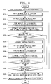
- Figure 3 is a flow chart explaining a deinterlacing method in use of a current field variable partition type, according to an exemplary embodiment of the present invention.
- the field partitioning part 132-1 partitions a current field read from the current field memory 110 into a plurality of macro blocks (S205). At this time, the size of a macro block is 16x16.
- the macro block partitioning part 132-2 partitions each of the macro blocks into a plurality of main blocks, respectively, using different 'main partition types' (S210).
- the main partition type means a partition type that partitions a macro block into a plurality of main blocks.
- the main partition types preferably partition a macro block into (i) one 16x16 main block (Type A), (ii) two 8x16 main blocks (Type B), (iii) two 16x8 main blocks (Type C), and (iv) four 8x8 main blocks (Type D).
- 'Type A' is not a partition in that the macro block and the main block are the same, but it can be regarded as one of the partition types for convenience sake.
- Figure 4 illustrates a macro block and main blocks as described above.
- the motion estimator 134 estimates a main motion vector group per main partition type applied in step S210 (S215).
- the main motion vector group indicates a set of motion vectors for main blocks generated in step S210.
- the motion estimator 134 estimates a main motion vector group when (i) the macro block is partitioned according to 'Type A' (hereinafter, 'A main motion vector group'), (ii) the macro block is partitioned according to 'Type B' (hereinafter, 'B main motion vector group'), (iii) the macro block is partitioned according to 'Type C' (hereinafter, 'C main motion vector group'), and (iv) the macro block is partitioned according to 'Type D' (hereinafter, 'D main motion vector group'), respectively.
- the motion estimator 134 stores the estimated main motion vector group in step S215 and the sum of main motion differences in the motion memory 136 by main partition types that are applied in step S210 (S220).
- the sum of main motion differences means the sum of motion differences being used as a basis for estimating motion vectors for the main blocks generated in step S210.
- Figure 5 illustrates the storage status of the motion memory 136 to which the main partition types 'Type A', 'Type B', 'Type C' and 'Type D' in step S210 are applied.
- a main motion vector group Motion_vector and a sum of main motion differences are stored for each main partition type.
- the motion estimator 134 estimates and stores a motion vector MV_A for the 16x16 main block in the motion memory 136. Moreover, the motion estimator 134 stores the sum of the motion difference MAD_A used as a basis for estimating the motion vector MV_A in the motion memory 136 as the sum of the main differences A. In short, the main motion vector group A is composed of one motion vector MV_A.
- the storage status of the motion memory 136 can be analogized from the case according to 'Type B'. Therefore, a detailed description thereof will be omitted.
- the determination unit 138 determines an optimum main partition type, on the basis of the sums of the main motion differences stored in the motion data memory 136 (S225). More specifically, the determination unit 138 determines a main partition type corresponding to a minimum value among the sums of the main motion differences in the memory 136 as the optimum main partition type.
- the determination part 138 determines the 'Type C' as the optimum main partition type in step S225.
- the deinterlacing device repartitions each of the main blocks (these have already been partitioned by their own main partition types) according to different sub partition types, respectively, and determines an optimum sub partition type using the repartitioned sub blocks (S235 - S255). Particularly, this corresponds to a case where the optimum main partition type determined in step S225 is the 'Type D'.
- the procedure from steps S235 - S255 are not executed.
- the macro block partitioning part 132-2 repartitions the main blocks having been partitioned by the optimum main partition type determined in step S225 into a plurality of sub blocks according to different sub partition types (S235).
- the sub partition type means a partition type for partitioning a main block into a plurality of sub blocks.
- the sub partition types preferably partition a main block into (i) one 8x8 sub block (Type D), (ii) two 4x8 sub blocks (Type E), (iii) two 8x4 sub blocks (Type F), or (iv) four 4x4 sub blocks (Type G).
- 'Type D' is not a partition in that the main block and the sub block are the same, but it is regarded as one of the partition types for convenience sake.
- FIG. 4 illustrates sub blocks described above.
- the motion estimator 134 estimates a sub motion vector group per sub partition type applied in step S235 (S240).
- the sub motion vector group indicates 'a set of motion vectors for sub blocks' generated in step S235.
- the motion estimator 134 stores the estimated sub motion vector group in step S240 and the sum of sub motion differences in the motion memory 136 by sub partition types that are applied in step S235 (S245).
- the sum of sub motion differences means the sum of motion differences being used as a basis for estimating motion vectors for the sub blocks generated in step S235.
- the determination unit 138 determines an optimum sub partition type, on the basis of sums of the sub motion differences stored in the motion data memory 136 (S250). In detail, the determination unit 138 designates a sub partition type corresponding to a minimum value among the sums of the sub motion differences as the optimum sub partition type.
- steps S235 - S250 continues until it is applied to every main block having been partitioned by the optimum main partition type (S255).
- steps S210 - S255 continues until it is applied to every macro block having been partitioned in step S205 (S260).
- Figure 6 is a picture for explaining how to determine the optimum partition type by area types.
- the 'H1' area is a low frequency area.
- the 'H1' area is preferably partitioned into large blocks in order to get a more accurate motion vector.
- the 'H2' area is a high frequency area.
- the 'H2' area is preferably partitioned into small blocks to in order to get a more accurate motion vector.
- both 'H1' and 'H2' areas are partitioned into blocks of the same size.
- the 'H1' area is partitioned into a large blocks (such as, Type A), and the 'H2' area is partitioned into small blocks (such as, Type G).
- the deinterlacing method of embodiments of the present invention makes it possible to calculate a motion vector more accurately.
- the adaptive field merging unit 150 merges the current field with a compensated field, referring to the optimum (main/sub) motion vector groups determined in steps S225 and S250 (S270).
- the slope of the optimum vector groups is a downward slope (-)
- the adaptive field merging unit 150 merges the compensated field into the lower portion the current field.
- the slope of the optimum motion vector groups is an upward slope (+)
- the adaptive field merging unit 150 merges the compensated field into the above portion of the current field.
- a progressive image is output from the adaptive field merging unit 150.
- steps S205 - S270 is performed again on a field that is received subsequent to the current field (that is, the next field).
- the deinterlacing method and device of embodiments of the present invention can be applied to an image display apparatus.
- embodiments of the present invention make it possible to calculate a more accurate motion vector by using the (optimum) field variable partition type, and proper deinterlacing can be executed based on the accurate motion vector. Moreover, because a proper merging type is determined on the basis of the motion vector, the most suitable deinterlacing can be performed. Accordingly, the user is provided with progressive images of the best quality.
Landscapes
- Engineering & Computer Science (AREA)
- Multimedia (AREA)
- Signal Processing (AREA)
- Computer Graphics (AREA)
- Compression Or Coding Systems Of Tv Signals (AREA)
- Television Systems (AREA)
Abstract
Description
- The present invention relates generally to a deinterlacing method and device. More specifically, the present invention relates to a deinterlacing method and device for converting an interlaced image to a progressive image.
- Deinterlacing is a technique that converts an interlaced image to a progressive image. The most common deinterlacing technique is reproducing a TV broadcast or video recorded on a DVD for display on a computer monitor.
- Figure 1 is a schematic block diagram of a conventional deinterlacing device. The following will now explain a deinterlacing procedure executed by the deinterlacing device shown in Figure 1.
- At first, a
motion vector calculator 30 calculates a motion vector using a current field and a previous field stored in acurrent field memory 10 and aprevious field memory 20, respectively. Amotion compensator 40 executes motion compensation on the current field using the motion vector calculated by themotion vector calculator 30. Then, afield merging unit 50 merges a 'current field' stored in thecurrent field memory 10 with a 'motion-compensated current field' generated by themotion compensator 40, to generate a progressive image. - As explained above, deinterlacing involves motion compensation using a calculated motion vector. Therefore, it is very important to calculate the motion vector as accurately as possible for proper deinterlacing. When deinterlacing is done properly, high quality progressive images (that is, vivid images) are provided to a user.
- For the calculation of a motion vector, a current field is partitioned into a plurality of blocks, and a motion vector is calculated for each of the blocks. For instance, a related deinterlacing device usually partitions a current field into a plurality of blocks, each block being 8x8 in size.
- To calculate a motion vector more accurately, however, it is more efficient to partition a high frequency area into small blocks, and a low frequency area into large blocks. Nevertheless, conventional deinterlacing methods execute deinterlacing by dividing a current field into fixed size blocks (such as 8x8). As a result, deinterlacing is often executed in a non-optimal manner.
- Embodiments of the present invention provide a deinterlacing device and method that uses a variable partition type for a field, through which a motion vector can be calculated more accurately and thus, deinterlacing is executed more accurately.
- According to the invention, there is provided a deinterlacing method, comprising the steps of dividing a current field into one or more first blocks, dividing the first blocks into one or more second blocks in a plurality of different ways, each of the plurality of different ways corresponding to a partition type, estimating a motion vector group for each partition type, the motion vector group being a set of motion vectors for each of the second blocks, determining an optimum partition type, designating the motion vector group corresponding to the optimum partition type as the optimum motion vector group, executing motion compensation on the current field using the optimum partition type and the optimum motion vector group and merging the current field and the motion compensated current field to thereby generate a progressive image.
- According to the invention, there is provided a deinterlacing method that includes partitioning one of a plurality of macro blocks composing a current field according to a first main partition type and a second main partition type. A first main motion vector group and a second main motion vector group are estimated, the first main motion vector group being a set of motion vectors for each of the plurality of main blocks generated by the first main partition type, and the second main motion vector group being a set of motion vectors for each of the plurality of main blocks generated by the second main partition type. One of the first main partition type and the second main partition type are determined as an optimum main partition type, and a main motion vector group corresponding to the optimum main partition type is determined as an optimum main motion vector group. Motion compensation is executed on the current field using the optimum main partition type and the optimum main motion vector group being determined. The current field and the motion compensated current field are merged thereby generating a progressive image.
- Preferably, in the determination step, the main partition type corresponding to a smaller sum of main motion differences among a first sum of main motion differences and a second sum of main motion differences is determined as the optimum main partition type, the first sum of main motion differences being the sum of motion differences used as a basis for estimating motion vectors for each of the plurality of main blocks generated by the first main partition type, and the second sum of main motion differences being the sum of motion differences used as a basis for estimating motion vectors for each of the plurality of main blocks generated by the second main partition type.
- Preferably, the macro block is a 16x16 block; the plurality of main blocks generated by the first main partition type are one of (one 16x16 block), (two 8x16 blocks), (two 16x8 blocks) and (four 8x8 blocks); and the plurality of main blocks generated by the second main partition type are one of (one 16x16 block), (two 8x16 blocks), (two 16x8 blocks) and (four 8x8 blocks).
- Preferably, if the second main partition type partitions the macro block into dense main blocks more than the first main partition type and is determined as the optimum main partition type, the method further includes repartitioning one of the plurality of main blocks generated by the first main partition type into sub blocks according to a first sub partition type and a second sub partition type, respectively. A first sub motion vector group and a second sub motion vector group are estimated, the first sub motion vector group being a set of sub motion vectors for each of the plurality of sub blocks generated by the first sub partition type, and the second sub motion vector group being a set of sub motion vectors for each of the plurality of sub blocks generated by the second sub partition type. One of the first sub partition type and the second sub partition type are determined as an optimum sub partition type, and a sub motion vector group corresponding to the optimum sub partition type is determined as an optimum sub motion vector group. Motion compensation is executed on the current field using the optimum sub partition type and the optimum sub motion vector group that have been determined.
- Preferably, in the determination step, the sub partition type corresponding to a smaller sum of sub motion differences among a first sum of sub motion differences and a second sum of sub motion differences is determined as the optimum sub partition type, the first sum of sub motion differences being the sum of motion differences used as a basis for estimating motion vectors for each of the plurality of sub blocks generated by the first sub partition type, and the second sum of sub motion differences being the sum of motion differences used as a basis for estimating motion vectors for each of the plurality of sub blocks generated by the second sub partition type.
- Preferably, the plurality of main blocks generated by the second main partition type are four 8x8 blocks; the plurality of sub blocks generated by the first sub partition type are one of (one 8x8 block), (two 4x8 blocks), (two 8x4 blocks) and (four 4x4 blocks); and the plurality of sub blocks generated by the second sub partition type are one of (one 8x8 block), (two 4x8 blocks), (two 8x4 blocks) and (four 4x4 blocks).
- Also, the progressive image is preferably generated by merging the compensated field into the lower portion of the current field if a slope of the optimum main motion vector group is a downward slope (-) and by merging the compensated field into the above portion of the current field if a slope of the determined motion vector groups is an upward slope (+).
- Another aspect of the present invention provides a deinterlacing device, including a partitioner for partitioning one of a plurality of macro blocks composing a current field according to a first main partition type and a second main partition type, respectively. A motion estimator estimates a first main motion vector group and a second main motion vector group, the first main motion vector group being a set of motion vectors for each of the plurality of main blocks generated by the first main partition type, and the second main motion vector group being a set of motion vectors for each of the plurality of main blocks generated by the second main partition type. A determination unit determines one of the first main partition type and the second main partition type as an optimum main partition type, and determines a main motion vector group corresponding to the optimum main partition type as an optimum main motion vector group. A motion compensator executes motion compensation on the current field using the optimum main partition type and the optimum main motion vector group being determined. An adaptive field merging unit merges the current field and the motion compensated current field and thereby generates a progressive image.
- Preferably, the determination unit determines the main partition type corresponding to a smaller sum of main motion differences among a first sum of main motion differences and a second sum of main motion differences as the optimum main partition type, the first sum of main motion differences being the sum of motion differences used as a basis for estimating motion vectors for each of the plurality of main blocks generated by the first main partition type, and the second sum of main motion differences being the sum of motion differences used as a basis for estimating motion vectors for each of the plurality of main blocks generated by the second main partition type.
- Preferably, the macro block is a 16x16 block; the plurality of main blocks generated by the first main partition type are one of (one 16x16 block), (two 8x16 blocks), (two 16x8 blocks) and (four 8x8 blocks); and the plurality of main blocks generated by the second main partition type are one of (one 16x16 block), (two 8x16 blocks), (two 16x8 blocks) and (four 8x8 blocks).
- Preferably, if the second main partition type partitions the macro block into dense main blocks more than the first main partition type and is determined as the optimum main partition type, the partitioner repartitions one of the plurality of main blocks generated by the first main partition type into sub blocks according to a first sub partition type and a second sub partition type, respectively. The motion estimator estimates a first sub motion vector group and a second sub motion vector group, the first sub motion vector group being a set of sub motion vectors for each of the plurality of sub blocks generated by the first sub partition type, and the second sub motion vector group being a set of sub motion vectors for each of the plurality of sub blocks generated by the second sub partition type. The determination unit determines one of the first sub partition type and the second sub partition type as an optimum sub partition type, and determines a sub motion vector group corresponding to the optimum sub partition type as an optimum sub motion vector group. The motion compensator executes motion compensation on the current field using the optimum sub partition type and the optimum sub motion vector group being determined.
- Preferably, the determination unit determines the sub partition type corresponding to a smaller sum of sub motion differences among a first sum of sub motion differences and a second sum of sub motion differences as the optimum sub partition type, the first sum of sub motion differences being the sum of motion differences used as a basis for estimating motion vectors for each of the plurality of sub blocks generated by the first sub partition type, and the second sum of sub motion differences being the sum of motion differences used as a basis for estimating motion vectors for each of the plurality of sub blocks generated by the second sub partition type.
- Preferably, the plurality of main blocks generated by the second main partition type are four 8x8 blocks; the plurality of sub blocks generated by the first sub partition type are one of (one 8x8 block), (two 4x8 blocks), (two 8x4 blocks) and (four 4x4 blocks); and the plurality of sub blocks generated by the second sub partition type are one of (one 8x8 block), (two 4x8 blocks), (two 8x4 blocks) and (four 4x4 blocks).
- Also, the adaptive field merging unit preferably generates a progressive image by merging the compensated field into the lower portion of the current field if a slope of the optimum main motion vector group is a downward slope (-), and by merging the compensated field into the above portion of the current field if a slope of the determined motion vector groups is an upward slope (+).
- The above aspects and features of the present invention will be more apparent by describing certain embodiments of the present invention with reference to the accompanying drawings, in which:
- Figure 1 is a schematic block diagram of a conventional deinterlacing device;
- Figure 2 is a schematic block diagram of a deinterlacing device according to an embodiment of the present invention, in which the deinterlacing device executes deinterlacing in use of a field variable partition type;
- Figure 3 is a flow chart explaining a deinterlacing method in use of a field variable partition type, according to an embodiment of the present invention;
- Figure 4 illustrates a macro block, main blocks and sub blocks according to an embodiment of the present invention;
- Figure 5 is a diagram illustrating a status of a motion memory according to an embodiment of the present invention; and
- Figure 6 is a picture for explaining how to determine an optimum partition type by area types according to an embodiment of the present invention.
- Figure 2 is a block diagram of a deinterlacing device according to an embodiment of the present invention. The deinterlacing device deinterlaces an input interlaced image to generate a progressive image. In particular, the deinterlacing device according to an exemplary embodiment of the present invention uses a field variable partition type.
- Referring to Figure 2, the deinterlacing device includes a
current field memory 110, aprevious field memory 120, amotion vector calculator 130, amotion compensator 140, and an adaptivefield merging unit 150. - In the exemplary deinterlacing device, an interlaced image is received. The
current field memory 110 stores a 'currently received field' (hereinafter, 'current field'), and theprevious field memory 120 stores a previous field that is delayed from the current field by one field period. As a result, a current field is stored in thecurrent field memory 110, whereas a previous field is stored in theprevious field memory 120. - The
motion vector calculator 130 calculates a motion vector using a current field and a previous field stored in thecurrent field memory 110 and theprevious field memory 120, respectively. For optimum deinterlacing, themotion vector calculator 130 partitions the current field into a plurality of blocks according to an optimum partition type, and calculates a set of motion vectors for partitioned blocks (hereinafter, 'motion vector group'). - The
motion vector calculator 130 includes apartitioner 132, amotion estimator 134, amotion data memory 136, and a determination unit 138. - The
partitioner 132 partitions a current field into a plurality of blocks. Thepartitioner 132 includes a field partitioning part 132-1 and a macro block partitioning part 132-2. - The field partitioning part 132-1 partitions a current field read from the
current field memory 110 into a plurality of macro blocks. The macro block partitioning part 132-2 partitions each of the macro blocks into a plurality of blocks. There are several ways for the macro block partitioning part 132-2 to partition a macro block into a plurality of blocks (hereinafter, referred to as 'partition types'). - The
motion estimator 134 estimates a motion vector for each of the blocks generated by the macro block partitioning part 132-2. To this end, themotion estimator 134 searches on a previous field a point where motion difference with a block is minimum, and estimates a vector heading from the searched point on the previous field for a position on the current field as a motion vector. With the motion difference, it becomes possible to hypothesize a Mean Absolute Difference (MAD). - A set of motion vectors for blocks (hereinafter, referred to as 'motion vector group') estimated by the
motion estimator 134 is stored in themotion data memory 136. Also, themotion data memory 136 stores a sum of motion differences that is used as a basis for estimating motion vectors for blocks (hereinafter, referred to as 'sum of motion differences). - The determination unit 138 determines an optimum partition type, on the basis of the sums of the motion differences stored in the
motion data memory 136. In more detail, the determination unit 138 designates a partition type corresponding to a minimum value among the sums of the motion differences as the optimum partition type. And, the determination unit 138 determines a motion vector group corresponding to the optimum partition type as an optimum motion vector group. - The determination unit 138 reads the optimum partition type and its corresponding motion vector group from the
motion data memory 136, and applies them to themotion compensator 140. - Then, the
motion compensator 140 executes motion compensation for a current field, by using the optimum partition types and the optimum motion vector groups applied from the determination unit 138. - The adaptive
field merging unit 150 merges a current field stored in thecurrent field memory 110 with a motion-compensated current field (hereinafter, referred to as 'compensated field) generated in themotion compensator 140. As a result, a progressive image is output from the adaptivefield merging unit 150. - To perform the merging process, the adaptive
field merging unit 150 refers to the motion vector groups determined by the determination unit 138. More specifically, if the slope of the determined motion vector groups is a downward slope (-), the adaptivefield merging unit 150 merges the compensated field into the lower portion of the current field. On the other hand, if the slope of the determined motion vector groups is an upward slope (+), the adaptivefield merging unit 150 merges the compensated field into the above portion of the current field. - The following will describe how the exemplary deinterlacing device of Figure 2 executes deinterlacing. Figure 3 is a flow chart explaining a deinterlacing method in use of a current field variable partition type, according to an exemplary embodiment of the present invention.
- Referring to Figure 3, first, the field partitioning part 132-1 partitions a current field read from the
current field memory 110 into a plurality of macro blocks (S205). At this time, the size of a macro block is 16x16. - Then, the macro block partitioning part 132-2 partitions each of the macro blocks into a plurality of main blocks, respectively, using different 'main partition types' (S210). Here, the main partition type means a partition type that partitions a macro block into a plurality of main blocks.
- There are several main partition types. For instance, if the macro block is a 16x16 block, the main partition types preferably partition a macro block into (i) one 16x16 main block (Type A), (ii) two 8x16 main blocks (Type B), (iii) two 16x8 main blocks (Type C), and (iv) four 8x8 main blocks (Type D). Technically speaking, 'Type A' is not a partition in that the macro block and the main block are the same, but it can be regarded as one of the partition types for convenience sake.
- Figure 4 illustrates a macro block and main blocks as described above.
- Afterwards, the
motion estimator 134 estimates a main motion vector group per main partition type applied in step S210 (S215). Here, the main motion vector group indicates a set of motion vectors for main blocks generated in step S210. - For example, suppose that Type A, Type B, Type C and Type D are utilized as main partition types in step S210. Then, the
motion estimator 134 estimates a main motion vector group when (i) the macro block is partitioned according to 'Type A' (hereinafter, 'A main motion vector group'), (ii) the macro block is partitioned according to 'Type B' (hereinafter, 'B main motion vector group'), (iii) the macro block is partitioned according to 'Type C' (hereinafter, 'C main motion vector group'), and (iv) the macro block is partitioned according to 'Type D' (hereinafter, 'D main motion vector group'), respectively. - Also, the
motion estimator 134 stores the estimated main motion vector group in step S215 and the sum of main motion differences in themotion memory 136 by main partition types that are applied in step S210 (S220). Here, the sum of main motion differences means the sum of motion differences being used as a basis for estimating motion vectors for the main blocks generated in step S210. - For better understanding of step S220, Figure 5 illustrates the storage status of the
motion memory 136 to which the main partition types 'Type A', 'Type B', 'Type C' and 'Type D' in step S210 are applied. - As shown in Figure 5, in the
motion memory 136, a main motion vector group Motion_vector and a sum of main motion differences are stored for each main partition type. - In detail, when the macro block is partitioned according to the 'Type A', the 16x16 macro block is partitioned into one 16x16 main block. Therefore, the
motion estimator 134 estimates and stores a motion vector MV_A for the 16x16 main block in themotion memory 136. Moreover, themotion estimator 134 stores the sum of the motion difference MAD_A used as a basis for estimating the motion vector MV_A in themotion memory 136 as the sum of the main differences A. In short, the main motion vector group A is composed of one motion vector MV_A. - On the other hand, when the macro block is partitioned according to the 'Type B', the 16x16 macro block is partitioned into two 8x16 main blocks. Therefore, the
motion estimator 134 estimates and stores motion vectors MV_B1, MV_B2 for those two 8x16 main blocks in themotion memory 136. Moreover, themotion estimator 134 stores the sum of motion differences MAD_B1, MAD_B2 used as a basis for estimating the motion vectors MV_B1, MV_B2 in themotion memory 136 as the sum of the main differences B (MAD_B = MAD_B1 + MAD_B2). In short, the main motion vector group B is composed of two motion vectors MV_B1, MV_B2. - When the macro block is partitioned according to the 'Type C' or 'Type D', the storage status of the
motion memory 136 can be analogized from the case according to 'Type B'. Therefore, a detailed description thereof will be omitted. - Referring again to Figure 3, the determination unit 138 determines an optimum main partition type, on the basis of the sums of the main motion differences stored in the motion data memory 136 (S225). More specifically, the determination unit 138 determines a main partition type corresponding to a minimum value among the sums of the main motion differences in the
memory 136 as the optimum main partition type. - To elaborate the above in reference to Figure 5, among the sums of the main motion differences MAD_A, MAD_B, MAD_C, MAD_D stored in the
motion memory 136, if the sum of main motion difference C MAD_C has a minimum value, the determination part 138 determines the 'Type C' as the optimum main partition type in step S225. - If the optimum main partition type determined in step S225 happens to be the densest main partition type (S230), the deinterlacing device repartitions each of the main blocks (these have already been partitioned by their own main partition types) according to different sub partition types, respectively, and determines an optimum sub partition type using the repartitioned sub blocks (S235 - S255). Particularly, this corresponds to a case where the optimum main partition type determined in step S225 is the 'Type D'.
- Meanwhile, if the optimum main partition type determined in step S225 is not the densest main partition type (that is, one of the 'Type A', 'Type B', or 'Type C' is determined as the optimum main partition type), the procedure from steps S235 - S255 are not executed.
- In effect, a person skilled in the art can analogize the procedure from steps S235 - S255 by steps S210 - S255, so the procedure will be explained briefly below.
- First, the macro block partitioning part 132-2 repartitions the main blocks having been partitioned by the optimum main partition type determined in step S225 into a plurality of sub blocks according to different sub partition types (S235). Here, the sub partition type means a partition type for partitioning a main block into a plurality of sub blocks.
- There are several sub partition types. For instance, if the macro block is an 8x8 block, the sub partition types preferably partition a main block into (i) one 8x8 sub block (Type D), (ii) two 4x8 sub blocks (Type E), (iii) two 8x4 sub blocks (Type F), or (iv) four 4x4 sub blocks (Type G). Technically speaking, 'Type D' is not a partition in that the main block and the sub block are the same, but it is regarded as one of the partition types for convenience sake.
- Figure 4 illustrates sub blocks described above.
- Later, the
motion estimator 134 estimates a sub motion vector group per sub partition type applied in step S235 (S240). Here, the sub motion vector group indicates 'a set of motion vectors for sub blocks' generated in step S235. - Also, the
motion estimator 134 stores the estimated sub motion vector group in step S240 and the sum of sub motion differences in themotion memory 136 by sub partition types that are applied in step S235 (S245). Here, the sum of sub motion differences means the sum of motion differences being used as a basis for estimating motion vectors for the sub blocks generated in step S235. - Next, the determination unit 138 determines an optimum sub partition type, on the basis of sums of the sub motion differences stored in the motion data memory 136 (S250). In detail, the determination unit 138 designates a sub partition type corresponding to a minimum value among the sums of the sub motion differences as the optimum sub partition type.
- The procedure in steps S235 - S250 continues until it is applied to every main block having been partitioned by the optimum main partition type (S255).
- Also, the procedure in steps S210 - S255 continues until it is applied to every macro block having been partitioned in step S205 (S260).
- Therefore, by the procedure explained in steps S205 - S260, motion vector data is calculated for one current field.
- Figure 6 is a picture for explaining how to determine the optimum partition type by area types. In Figure 6, the 'H1' area is a low frequency area. Thus, the 'H1' area is preferably partitioned into large blocks in order to get a more accurate motion vector. On the other hand, the 'H2' area is a high frequency area. Thus, the 'H2' area is preferably partitioned into small blocks to in order to get a more accurate motion vector.
- In conventional deinterlacing methods, both 'H1' and 'H2' areas are partitioned into blocks of the same size. In contrast, according to the deinterlacing method of an embodiment of the present invention, the 'H1' area is partitioned into a large blocks (such as, Type A), and the 'H2' area is partitioned into small blocks (such as, Type G). As such, the deinterlacing method of embodiments of the present invention makes it possible to calculate a motion vector more accurately.
- Turning back to Figure 3, using the optimum (main/sub) partition types and their corresponding optimum (main/sub) motion vector groups determined in steps S225 and S250 by the determination unit 138, motion compensation is executed on a current field (S265).
- Also, the adaptive
field merging unit 150 merges the current field with a compensated field, referring to the optimum (main/sub) motion vector groups determined in steps S225 and S250 (S270). In detail, if the slope of the optimum vector groups is a downward slope (-), the adaptivefield merging unit 150 merges the compensated field into the lower portion the current field. On the other hand, if the slope of the optimum motion vector groups is an upward slope (+), the adaptivefield merging unit 150 merges the compensated field into the above portion of the current field. As a result, a progressive image is output from the adaptivefield merging unit 150. - Afterwards, the procedure in steps S205 - S270 is performed again on a field that is received subsequent to the current field (that is, the next field).
- So far, the deinterlacing method and device in use of the field variable partition type have been explained in detail. The deinterlacing method and device of embodiments of the present invention can be applied to an image display apparatus.
- In conclusion, embodiments of the present invention make it possible to calculate a more accurate motion vector by using the (optimum) field variable partition type, and proper deinterlacing can be executed based on the accurate motion vector. Moreover, because a proper merging type is determined on the basis of the motion vector, the most suitable deinterlacing can be performed. Accordingly, the user is provided with progressive images of the best quality.
- The foregoing embodiment and advantages are merely exemplary and are not to be construed as limiting the present invention. The present teaching can be readily applied to other types of apparatuses. Also, the description of the embodiments of the present invention is intended to be illustrative, and not to limit the scope of the claims, and many alternatives, modifications, and variations will be apparent to those skilled in the art.
Claims (17)
- A deinterlacing method, comprising the steps of:dividing a current field into one or more first blocks;dividing the first blocks into one or more second blocks in a plurality of different ways, each of the plurality of different ways corresponding to a partition type;estimating a motion vector group for each partition type, the motion vector group being a set of motion vectors for each of the second blocks;determining an optimum partition type;designating the motion vector group corresponding to the optimum partition type as the optimum motion vector group;executing motion compensation on the current field using the optimum partition type and the optimum motion vector group; andmerging the current field and the motion compensated current field to thereby generate a progressive image.
- A method according to claim 1, wherein each partition type is associated with a sum of motion differences, said motion differences being used to estimate the motion vectors for each of the second blocks, wherein the step of determining an optimum partition type comprises selecting the partition type that has the smallest value for the sum of motion differences.
- A method according to claim 1 or 2, wherein each of the partition types comprise a division of a block into a plurality of sub-blocks, and if the optimum partition type comprises more sub-blocks than any of the other partition types, the method further comprises dividing each of the second blocks into one or more third blocks, in accordance with a further plurality of partition types..
- A deinterlacing method, comprising the steps of:partitioning one of a plurality of macro blocks composing a current field according to a first main partition type and a second main partition type, respectively;estimating a first main motion vector group and a second main motion vector group, the first main motion vector group being a set of motion vectors for each of the plurality of main blocks generated by the first main partition type, and the second main motion vector group being a set of motion vectors for each of the plurality of main blocks generated by the second main partition type;determining one of the first main partition type and the second main partition type as an optimum main partition type, and determining a main motion vector group corresponding to the optimum main partition type as an optimum main motion vector group;executing motion compensation on the current field using the optimum main partition type and the optimum main motion vector group being determined; andmerging the current field and the motion compensated current field and thereby generating a progressive image.
- The method according to claim 4, wherein, in the determination step, the main partition type corresponding to a smaller sum of main motion differences among a first sum of main motion differences and a second sum of main motion differences is determined as the optimum main partition type, the first sum of main motion differences being the sum of motion differences used as a basis for estimating motion vectors for each of the plurality of main blocks generated by the first main partition type, and the second sum of main motion differences being the sum of motion differences used as a basis for estimating motion vectors for each of the plurality of main blocks generated by the second main partition type.
- The method according to claim 4 or 5, wherein the macro block is a 16x16 block;
the plurality of main blocks generated by the first main partition type are one of (one 16x16 block), (two 8x16 blocks), (two 16x8 blocks) and (four 8x8 blocks); and
the plurality of main blocks generated by the second main partition type are one of (one 16x16 block), (two 8x16 blocks), (two 16x8 blocks) and (four 8x8 blocks). - The method according to claim 4, 5 or 6, wherein, if the second main partition type partitions the macro block into dense main blocks more than the first main partition type and is determined as the optimum main partition type, the method further comprises the steps of:repartitioning one of the plurality of main blocks generated by the second main partition type into sub blocks according to a first sub partition type and a second sub partition type, respectively;estimating a first sub motion vector group and a second sub motion vector group, the first sub motion vector group being a set of sub motion vectors for each of the plurality of sub blocks generated by the first sub partition type, and the second sub motion vector group being a set of sub motion vectors for each of the plurality of sub blocks generated by the second sub partition type;determining one of the first sub partition type and the second sub partition type as an optimum sub partition type, and determining a sub motion vector group corresponding to the optimum sub partition type as an optimum sub motion vector group; andexecuting motion compensation on the current field using the optimum sub partition type and the optimum sub motion vector group being determined.
- The method according to claim 7, wherein, in the determination step, the sub partition type corresponding to a smaller sum of sub motion differences among a first sum of sub motion differences and a second sum of sub motion differences is determined as the optimum sub partition type, the first sum of sub motion differences being the sum of motion differences used as a basis for estimating motion vectors for each of the plurality of sub blocks generated by the first sub partition type, and the second sum of sub motion differences being the sum of motion differences used as a basis for estimating motion vectors for each of the plurality of sub blocks generated by the second sub partition type.
- The method according to claim 7, wherein the plurality of main blocks generated by the second main partition type are four 8x8 blocks;
the plurality of sub blocks generated by the first sub partition type are one of (one 8x8 block), (two 4x8 blocks), (two 8x4 blocks) and (four 4x4 blocks); and
the plurality of sub blocks generated by the second sub partition type are one of (one 8x8 block), (two 4x8 blocks), (two 8x4 blocks) and (four 4x4 blocks). - The method according to claim 4, wherein, in the merging step, the progressive image is generated by merging the compensated field into the lower portion of the current field if a slope of the optimum main motion vector group is a downward slope (-), and by merging the compensated field into the upper portion of the current field if the slope of the optimum main motion vector groups is an upward slope (+).
- A deinterlacing device, comprising:a partitioner for partitioning one of a plurality of macro blocks composing a current field according to a first main partition type and a second main partition type, respectively;a motion estimator for estimating a first main motion vector group and a second main motion vector group, the first main motion vector group being a set of motion vectors for each of the plurality of main blocks generated by the first main partition type, and the second main motion vector group being a set of motion vectors for each of the plurality of main blocks generated by the second main partition type;a determination unit for determining one of the first main partition type and the second main partition type as an optimum main partition type, and determining a main motion vector group corresponding to the optimum main partition type as an optimum main motion vector group;a motion compensator for executing motion compensation on the current field using the optimum main partition type and the optimum main motion vector group being determined; andan adaptive filed merging unit for merging the current field and the motion compensated current field and thereby generating a progressive image.
- The device according to claim 11, wherein the determination unit determines the main partition type corresponding to a smaller sum of main motion differences among a first sum of main motion differences and a second sum of main motion differences as the optimum main partition type, the first sum of main motion differences being the sum of motion differences used as a basis for estimating motion vectors for each of the plurality of main blocks generated by the first main partition type, and the second sum of main motion differences being the sum of motion differences used as a basis for estimating motion vectors for each of the plurality of main blocks generated by the second main partition type.
- The device according to claim 11, wherein the macro block is a 16x16 block;
the plurality of main blocks generated by the first main partition type are one of (one 16x16 block), (two 8x16 blocks), (two 16x8 blocks) and (four 8x8 blocks); and
the plurality of main blocks generated by the second main partition type are one of (one 16x16 block), (two 8x16 blocks), (two 16x8 blocks) and (four 8x8 blocks). - The device according to claim 11, wherein, if the second main partition type partitions the macro block into dense main blocks more than the first main partition type and is determined as the optimum main partition type,
the partitioner repartitions one of the plurality of main blocks generated by the second main partition type into sub blocks according to a first sub partition type and a second sub partition type, respectively;
the motion estimator estimates a first sub motion vector group and a second sub motion vector group, the first sub motion vector group being a set of sub motion vectors for each of the plurality of sub blocks generated by the first sub partition type, and the second sub motion vector group being a set of sub motion vectors for each of the plurality of sub blocks generated by the second sub partition type;
the determination unit determines one of the first sub partition type and the second sub partition type as an optimum sub partition type, and determining a sub motion vector group corresponding to the optimum sub partition type as an optimum sub motion vector group; and
the motion compensator executes motion compensation on the current field using the optimum sub partition type and the optimum sub motion vector group being determined. - The device according to claim 14, wherein, the determination unit determines the sub partition type corresponding to a smaller sum of sub motion differences among a first sum of sub motion differences and a second sum of sub motion differences as the optimum sub partition type, the first sum of sub motion differences being the sum of motion differences used as a basis for estimating motion vectors for each of the plurality of sub blocks generated by the first sub partition type, and the second sum of sub motion differences being the sum of motion differences used as a basis for estimating motion vectors for each of the plurality of sub blocks generated by the second sub partition type.
- The device according to claim 14, wherein the plurality of main blocks generated by the second main partition type are four 8x8 blocks;
the plurality of sub blocks generated by the first sub partition type are one of (one 8x8 block), (two 4x8 blocks), (two 8x4 blocks) and (four 4x4 blocks); and
the plurality of sub blocks generated by the second sub partition type are one of (one 8x8 block), (two 4x8 blocks), (two 8x4 blocks) and (four 4x4 blocks). - The device according to claim 11, wherein the adaptive field merging unit generates a progressive image by merging the compensated field into the lower portion of the current field if a slope of the optimum main motion vector group is a downward slope (-), and by merging the compensated field into the above portion of the current field if the slope of the optimum main motion vector groups is an upward slope (+).
Applications Claiming Priority (1)
| Application Number | Priority Date | Filing Date | Title |
|---|---|---|---|
| KR1020040093907A KR101042623B1 (en) | 2004-11-17 | 2004-11-17 | Deinterlacing method and apparatus using field variable division method |
Publications (1)
| Publication Number | Publication Date |
|---|---|
| EP1659791A1 true EP1659791A1 (en) | 2006-05-24 |
Family
ID=36001116
Family Applications (1)
| Application Number | Title | Priority Date | Filing Date |
|---|---|---|---|
| EP05110610A Withdrawn EP1659791A1 (en) | 2004-11-17 | 2005-11-10 | Deinterlacing using motion estimation and compenstation |
Country Status (3)
| Country | Link |
|---|---|
| US (1) | US7535513B2 (en) |
| EP (1) | EP1659791A1 (en) |
| KR (1) | KR101042623B1 (en) |
Cited By (1)
| Publication number | Priority date | Publication date | Assignee | Title |
|---|---|---|---|---|
| US8922711B2 (en) | 2006-08-29 | 2014-12-30 | Realtek Semiconductor Corp. | Method and apparatus for de-interlacing video data |
Families Citing this family (15)
| Publication number | Priority date | Publication date | Assignee | Title |
|---|---|---|---|---|
| US8165209B2 (en) * | 2007-09-24 | 2012-04-24 | General Instrument Corporation | Method and apparatus for providing a fast motion estimation process |
| CA2707860A1 (en) * | 2007-12-11 | 2009-06-18 | Thomson Licensing | Methods and systems for transcoding within the distribution chain |
| US8355077B2 (en) * | 2008-03-27 | 2013-01-15 | Csr Technology Inc. | Adaptive windowing in motion detector for deinterlacer |
| WO2011155758A2 (en) * | 2010-06-07 | 2011-12-15 | ㈜휴맥스 | Method for encoding/decoding high-resolution image and device for performing same |
| US9137533B2 (en) * | 2010-01-15 | 2015-09-15 | Samsung Electronics Co., Ltd. | Method and apparatus for encoding video using variable partitions for predictive encoding, and method and apparatus for decoding video using variable partitions for predictive encoding |
| CN105025298B (en) * | 2010-01-19 | 2019-04-16 | 三星电子株式会社 | The method and apparatus that image is encoded/decoded |
| WO2011090313A2 (en) | 2010-01-19 | 2011-07-28 | 삼성전자 주식회사 | Method and apparatus for encoding/decoding images using a motion vector of a previous block as a motion vector for the current block |
| CN105025301B (en) * | 2010-01-19 | 2019-08-23 | 三星电子株式会社 | Image decoding apparatus |
| US9788019B2 (en) | 2011-03-09 | 2017-10-10 | Hfi Innovation Inc. | Method and apparatus of transform unit partition with reduced complexity |
| CN102857763B (en) * | 2011-06-30 | 2016-02-17 | 华为技术有限公司 | A kind of coding/decoding method based on infra-frame prediction and decoding device |
| KR101955374B1 (en) * | 2011-06-30 | 2019-05-31 | 에스케이 텔레콤주식회사 | Method and Apparatus for Image Encoding/Decoding By Fast Coding Unit Mode Decision |
| CN104363451B (en) | 2014-10-27 | 2019-01-25 | 华为技术有限公司 | Image prediction method and relevant apparatus |
| KR101997604B1 (en) * | 2019-01-22 | 2019-07-08 | 에스케이 텔레콤주식회사 | Method and Apparatus for Video Encoding/Decoding |
| US12010305B2 (en) * | 2019-03-11 | 2024-06-11 | Apple Inc. | Method for encoding/decoding image signal, and device therefor |
| TWI768324B (en) * | 2020-04-16 | 2022-06-21 | 瑞昱半導體股份有限公司 | Image processing method and image processing device |
Citations (3)
| Publication number | Priority date | Publication date | Assignee | Title |
|---|---|---|---|---|
| EP1164792A2 (en) | 2000-06-13 | 2001-12-19 | Samsung Electronics Co., Ltd. | Format converter using bidirectional motion vector and method thereof |
| US6618439B1 (en) * | 1999-07-06 | 2003-09-09 | Industrial Technology Research Institute | Fast motion-compensated video frame interpolator |
| AU2003264648A1 (en) * | 2002-12-03 | 2004-06-24 | Samsung Electronics Co., Ltd | Deinterlacing apparatus and method |
Family Cites Families (7)
| Publication number | Priority date | Publication date | Assignee | Title |
|---|---|---|---|---|
| KR0180171B1 (en) * | 1995-06-28 | 1999-05-01 | 배순훈 | Block motion estimation method |
| KR100631497B1 (en) * | 2000-01-13 | 2006-10-09 | 엘지전자 주식회사 | De-interlacing method and apparatus |
| US6473460B1 (en) * | 2000-03-31 | 2002-10-29 | Matsushita Electric Industrial Co., Ltd. | Method and apparatus for calculating motion vectors |
| US6650705B1 (en) * | 2000-05-26 | 2003-11-18 | Mitsubishi Electric Research Laboratories Inc. | Method for encoding and transcoding multiple video objects with variable temporal resolution |
| KR100644601B1 (en) * | 2000-09-30 | 2006-11-10 | 삼성전자주식회사 | De-interlacing device using motion compensation interpolation and method |
| KR100437101B1 (en) | 2001-11-01 | 2004-06-23 | 보인정밀 주식회사 | Method and circuit for converting interlaced scanning signal to progressive scanning signal using motion compensation |
| US7362374B2 (en) * | 2002-08-30 | 2008-04-22 | Altera Corporation | Video interlacing using object motion estimation |
-
2004
- 2004-11-17 KR KR1020040093907A patent/KR101042623B1/en not_active IP Right Cessation
-
2005
- 2005-11-10 EP EP05110610A patent/EP1659791A1/en not_active Withdrawn
- 2005-11-17 US US11/280,408 patent/US7535513B2/en not_active Expired - Fee Related
Patent Citations (3)
| Publication number | Priority date | Publication date | Assignee | Title |
|---|---|---|---|---|
| US6618439B1 (en) * | 1999-07-06 | 2003-09-09 | Industrial Technology Research Institute | Fast motion-compensated video frame interpolator |
| EP1164792A2 (en) | 2000-06-13 | 2001-12-19 | Samsung Electronics Co., Ltd. | Format converter using bidirectional motion vector and method thereof |
| AU2003264648A1 (en) * | 2002-12-03 | 2004-06-24 | Samsung Electronics Co., Ltd | Deinterlacing apparatus and method |
Non-Patent Citations (6)
| Title |
|---|
| CHAN M H ET AL: "VARIABLE SIZE BLOCK MATCHING MOTION COMPENSATION WITH APPLICATIONS TO VIDEO CODING", IEE PROCEEDINGS I. SOLID- STATE & ELECTRON DEVICES, INSTITUTION OF ELECTRICAL ENGINEERS. STEVENAGE, GB, vol. 137, no. 4, 1 August 1990 (1990-08-01), pages 205 - 212, XP000147601, ISSN: 0956-3776 * |
| DUFAUX F ET AL: "MOTION ESTIMATION TECHNIQUES FOR DIGITAL TV: A REVIEW AND A NEW CONTRIBUTION", PROCEEDINGS OF THE IEEE, IEEE. NEW YORK, US, vol. 83, no. 6, June 1995 (1995-06-01), pages 858 - 875, XP000518740, ISSN: 0018-9219 * |
| L WANG ET AL.: "Interlace Coding Tools for H.26L Video Coding", ITU STUDY GROUP 16 - VIDEO CODING EXPERTS GROUP |
| M CHAN ET AL.: "Variable size block matching motion compensation with applications to video coding", IEE PROCEEDINGS, vol. 137, no. 4, August 1990 (1990-08-01), XP000147601 |
| RICHARDSON IAIN E G: "H.264/MPEG-4 part 10 tutorials, switching P and I slices", INTERNET CITATION, 31 January 2003 (2003-01-31), XP002952897, Retrieved from the Internet <URL:WWW.VCODEX.COM> [retrieved on 20030507] * |
| WANG L ET AL: "Interlace Coding Tools for H.26L Video Coding", ITU STUDY GROUP 16 - VIDEO CODING EXPERTS GROUP VCEG-O37.DOC, 4 December 2001 (2001-12-04), pages 1 - 20, XP002240263, Retrieved from the Internet <URL:http://standards.pictel.com/ftp/q15-site/0112_Pat/VCEG-O37.doc> * |
Cited By (1)
| Publication number | Priority date | Publication date | Assignee | Title |
|---|---|---|---|---|
| US8922711B2 (en) | 2006-08-29 | 2014-12-30 | Realtek Semiconductor Corp. | Method and apparatus for de-interlacing video data |
Also Published As
| Publication number | Publication date |
|---|---|
| US20060125956A1 (en) | 2006-06-15 |
| KR101042623B1 (en) | 2011-06-20 |
| KR20060053517A (en) | 2006-05-22 |
| US7535513B2 (en) | 2009-05-19 |
Similar Documents
| Publication | Publication Date | Title |
|---|---|---|
| EP1659791A1 (en) | Deinterlacing using motion estimation and compenstation | |
| CN102088589B (en) | Frame rate conversion using bi-directional, local and global motion estimation | |
| KR100604394B1 (en) | A frame interpolation method, apparatus and image display system using the same | |
| CN1992789B (en) | Motion estimator and motion method | |
| JP5089610B2 (en) | Block-based motion estimation method and apparatus | |
| CN104469379A (en) | Generating an output frame for inclusion in a video sequence | |
| KR100579493B1 (en) | Apparatus and method for generating motion vectors | |
| CN104219533B (en) | A kind of bi-directional motion estimation method and up-conversion method of video frame rate and system | |
| US20030161403A1 (en) | Apparatus for and method of transforming scanning format | |
| CN100499778C (en) | Method and device for camera model parameter estimation using iterative center of mass | |
| JP2003274416A (en) | Adaptive motion estimation apparatus and method | |
| JP4564564B2 (en) | Moving picture reproducing apparatus, moving picture reproducing method, and moving picture reproducing program | |
| KR101756842B1 (en) | Method and apparatus for image frame interpolation | |
| EP2306401A1 (en) | Motion estimating method and image processing apparatus | |
| US20040252895A1 (en) | Pixel-data selection device to provide motion compensation, and a method thereof | |
| JP2005505841A (en) | Apparatus and method for motion estimation | |
| KR100855976B1 (en) | Frame interpolation device and frame interpolation method for estimating motion by separating background and moving objects | |
| KR20070074781A (en) | Frame rate inverter | |
| KR20040047963A (en) | Unit for and method of motion estimation and image processing apparatus provided with such motion estimate unit | |
| KR20070063304A (en) | Motion Estimator and Motion Estimation Method | |
| WO2015085922A1 (en) | Method and apparatus for frame rate up-conversion | |
| US20120274845A1 (en) | Image processing device and method, and program | |
| US10282831B2 (en) | Method and apparatus for motion compensated noise reduction | |
| TWI379254B (en) | ||
| KR100969420B1 (en) | Frame rate conversion method |
Legal Events
| Date | Code | Title | Description |
|---|---|---|---|
| PUAI | Public reference made under article 153(3) epc to a published international application that has entered the european phase |
Free format text: ORIGINAL CODE: 0009012 |
|
| AK | Designated contracting states |
Kind code of ref document: A1 Designated state(s): AT BE BG CH CY CZ DE DK EE ES FI FR GB GR HU IE IS IT LI LT LU LV MC NL PL PT RO SE SI SK TR |
|
| AX | Request for extension of the european patent |
Extension state: AL BA HR MK YU |
|
| 17P | Request for examination filed |
Effective date: 20060714 |
|
| 17Q | First examination report despatched |
Effective date: 20061020 |
|
| AKX | Designation fees paid |
Designated state(s): DE GB NL |
|
| RAP1 | Party data changed (applicant data changed or rights of an application transferred) |
Owner name: SAMSUNG ELECTRONICS CO., LTD. |
|
| STAA | Information on the status of an ep patent application or granted ep patent |
Free format text: STATUS: THE APPLICATION HAS BEEN WITHDRAWN |
|
| 18W | Application withdrawn |
Effective date: 20161128 |