EP1617269A1 - Light scanning microscope with linear scanning - Google Patents
Light scanning microscope with linear scanning Download PDFInfo
- Publication number
- EP1617269A1 EP1617269A1 EP05012840A EP05012840A EP1617269A1 EP 1617269 A1 EP1617269 A1 EP 1617269A1 EP 05012840 A EP05012840 A EP 05012840A EP 05012840 A EP05012840 A EP 05012840A EP 1617269 A1 EP1617269 A1 EP 1617269A1
- Authority
- EP
- European Patent Office
- Prior art keywords
- light
- detection
- reflective
- illumination
- coupling
- Prior art date
- Legal status (The legal status is an assumption and is not a legal conclusion. Google has not performed a legal analysis and makes no representation as to the accuracy of the status listed.)
- Withdrawn
Links
- 238000001514 detection method Methods 0.000 claims abstract description 25
- 238000005286 illumination Methods 0.000 claims abstract description 21
- 210000001747 pupil Anatomy 0.000 claims abstract description 15
- 230000008878 coupling Effects 0.000 claims abstract description 14
- 238000010168 coupling process Methods 0.000 claims abstract description 14
- 238000005859 coupling reaction Methods 0.000 claims abstract description 14
- 238000000605 extraction Methods 0.000 claims abstract 3
- 229910000831 Steel Inorganic materials 0.000 claims 2
- 239000010959 steel Substances 0.000 claims 2
- 230000003287 optical effect Effects 0.000 description 3
- 230000000694 effects Effects 0.000 description 2
- 230000005284 excitation Effects 0.000 description 2
- 230000005540 biological transmission Effects 0.000 description 1
- 230000015572 biosynthetic process Effects 0.000 description 1
- 238000003384 imaging method Methods 0.000 description 1
- 230000003993 interaction Effects 0.000 description 1
- 238000004020 luminiscence type Methods 0.000 description 1
- 239000011159 matrix material Substances 0.000 description 1
- 238000011144 upstream manufacturing Methods 0.000 description 1
Images


Classifications
-
- G—PHYSICS
- G02—OPTICS
- G02B—OPTICAL ELEMENTS, SYSTEMS OR APPARATUS
- G02B21/00—Microscopes
- G02B21/0004—Microscopes specially adapted for specific applications
- G02B21/002—Scanning microscopes
- G02B21/0024—Confocal scanning microscopes (CSOMs) or confocal "macroscopes"; Accessories which are not restricted to use with CSOMs, e.g. sample holders
- G02B21/0032—Optical details of illumination, e.g. light-sources, pinholes, beam splitters, slits, fibers
-
- G—PHYSICS
- G02—OPTICS
- G02B—OPTICAL ELEMENTS, SYSTEMS OR APPARATUS
- G02B21/00—Microscopes
- G02B21/0004—Microscopes specially adapted for specific applications
- G02B21/002—Scanning microscopes
Definitions
- DE10257237 A1 describes a beam splitter, inter alia for a line scanner.
- a line scanner the sample is illuminated with a line focus (eg along the X coordinate) which is shifted in the coordinate (Y) perpendicular to the line.
- the light source is focused linearly in an intermediate image plane of the microscope device by means of optics.
- optics By focusing in the Y direction in the intermediate image, for example by a cylindrical lens, results in a diffraction-limited line-shaped intensity distribution along X on the sample.
- the light is imaged in the pupil of the microscope assembly.
- the pupil planes and the scanner are pupil planes of the microscope arrangement conjugate to each other and to the rear focal plane of the objective, so that the scanner can move the linear and diffraction-limited focused intensity distribution perpendicular thereto (y-coordinate in the sample) ).
- the image in the sample via a scan optics, the tube lens and the lens.
- Relay optics create conjugated pupil planes of the microscope assembly. Due to the nature of the sample interaction, for example in the case of a fluorescence or luminescence excitation, the light emitted by the sample is of little spatial coherence. That is, each point excited in the sample radiates substantially independently of the neighboring points as spot radiators in all spatial directions.
- the optics eg a microscope objective
- the pupil is the element that separates the excitation from the detection light. He is trained as described in DE.
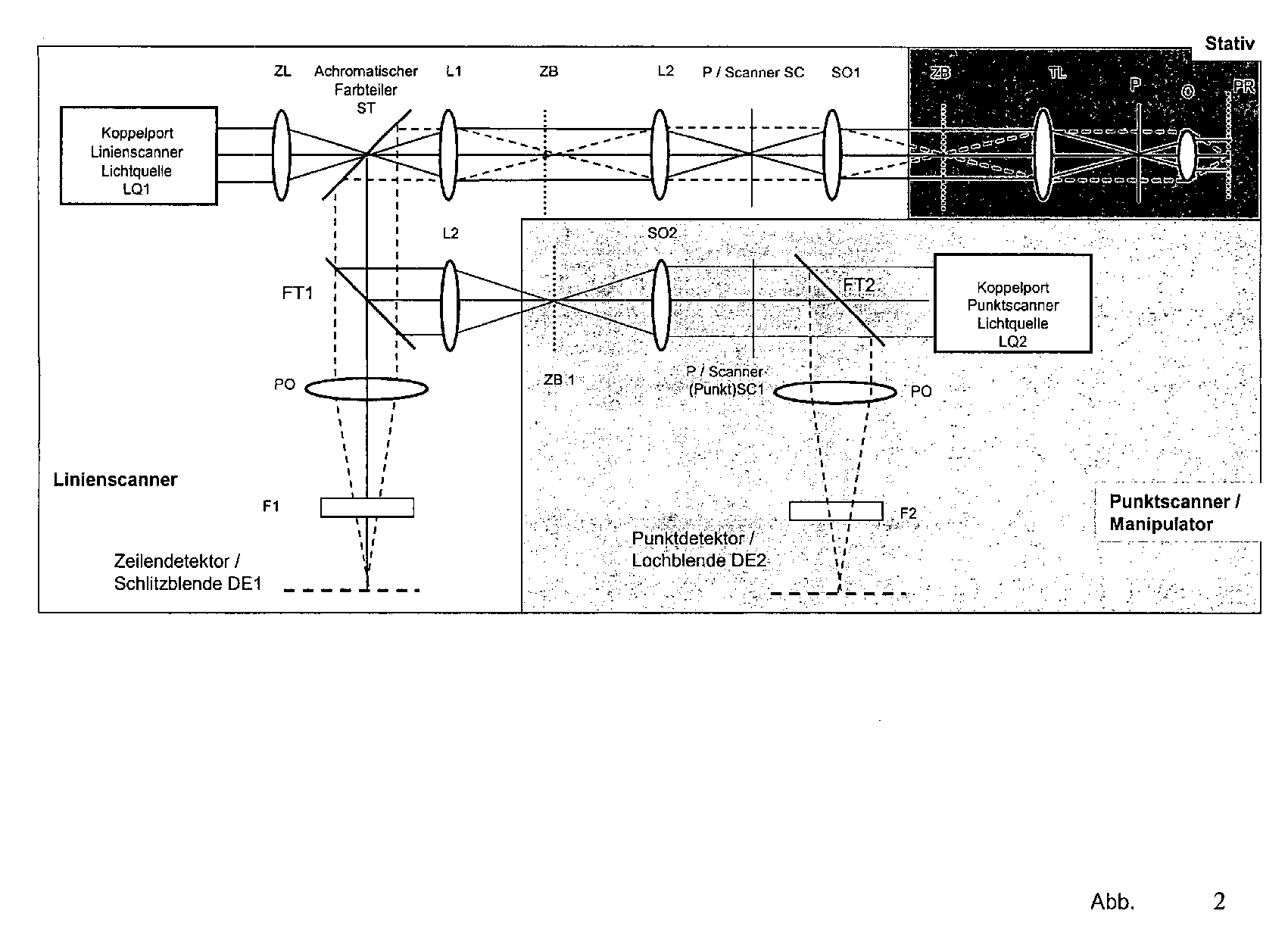
- a wide-field light source LQ with a suitable optical system for generating a line of illumination, for example a cylindrical lens ZL, linearly in a plane conjugate to the pupil P of the microscope objective 0 level in which there is a beam splitter ST constructed according to DE 10257237A1 which is the subject of the disclosure, which here has a narrow line-shaped transmissive area, over which the line passes via a transmission optics L1, L2, scanning optics SO, tube lens TL and objective 0 in FIG the sample PR is mapped.
- a scanner SC Disposed in a pupil P is a scanner SC which rapidly moves the line across the sample in a scan direction perpendicular to the line extent.
- the light coming from the sample (dashed) is deflected by the up to the narrow transmissive region in the direction of detection reflecting beam splitter via an interchangeable filter F and a detection optics PO in the direction of a detector DE1, which may be arranged upstream of a slit diaphragm.
- light sources LQ1, LQ2 are shown, which can also be formed by branching a single light source, with wavelength and intensity being advantageously adjustable.
- achromatic beam splitters as described in DE ... there is the particular advantage that the same wavelength can be used for both light sources LQ1, LQ2, which can also be formed by dividing one and the same light source.
- the intermediate images ZB and ZB1 are mutually conjugate planes.
- the pupil planes of the microscope arrangement P are mutually conjugate planes.
- the respective conjugate planes are generated by the effect of the respectively intermediate optics (which act as relay optics - beam paths are drawn only schematically).
- LQ 2 may be a point scanner.
- the illumination light of the dot scanner can advantageously be used for specific manipulation (eg uncaging) on certain sample areas.
- a scanner SC1 an X / Y scanner
- the illumination light of LQ2 is superimposed into the detection beam path of the line scanner via a conventional dichroic color splitter FT1 and passes over the reflective area of the splitter ST in the direction of the sample PR ,
- the reflecting region of the beam splitter ST is utilized for the purpose of reflecting in another scanning beam path.
- the light coming from the sample reaches the detector DE1 and, on the other hand, depending on the design of the color splitter FT1, also passes via a further color splitter FT2 in the direction of a second detector DE2.
- fluorescent light excited by LQ1 from the sample reaches the detector DE1 with a corresponding design of FT1, while reflected light from the dot scanner LQ2 reaches the detector DE2.
- different fluorescence wavelengths excited by LQ1 or LQ2 can also reach the different detectors DE1 and DE2.
- the scanner SC1 Since here the light moved by the scanner SC1 is additionally moved by the scanner 1, the scanner SC1 must be controlled so that it compensates the movement of the scanner SC and additionally realizes a relative position for line illumination. This is easy to realize when scanner SC1 moves slower compared to scanner SC2.
- the fluorescent light excited by LQ2 can also be directed to the line detector DE1. Depending on the position of the scanner 2, the fuorescence spot moves across the line detector DE 1, ie the light is separated in front of the scanner 2 in the direction DE1.
- a coupling point KS1 is provided, which may be a separate module and is located between a microscope stand S with tube lens and lens, a first scanning unit SC 1 and a second scanning unit SC 2.
- SC 1 may include the described line scanner and SC 2 may include a point scanner for scanning and / or manipulation.
- SC1 and SC 2 can be connected to interfaces on KS1.
- several mutually conjugated intermediate images ZB are available in KS1 (via the optics L1, L2). The respective conjugate levels are through the effect of intervening between each optics (beam paths only schematically) generated.
- the beam splitter ST1 which is constructed analogously to the beam splitter ST (DE%), A line is imaged onto the sample through the transmissive region.
- the light is directed via reflectors RF not as in Fig.4 on the back of the beam splitter ST1 but on the back of the scanner SC33, which is here on the front and back mirrors mirrored and with its back the coming of the sample of the line scanner (LQ1 passes from the top to the front of the scanner mirror) forwarded sample light (descannt) to the detector DE1.
- FT 3 is in this case designed so that it passes the light intended for the detector DE1 and reflects only the light intended for DE2.
- the light excited by the line scanner is not picked up as in FIG. 5, but passes directly through FT1 onto an area detector (CCD matrix).
- gated camera ie the line-shaped light distribution that comes from the sample runs in the scan direction over the receiver surfaces, thereby recording a sample image.
- further scan arrangements can in principle also be incorporated by cascading (arrangement of further color splitters FT in a common beam path.)
- the scan arrangements can be any imaging arrangements, such as the point scanners mentioned above, but also resonance point scanners, nipkowscanners, line scanners and multipoint scanners It is advantageous in this case that they have an intermediate image plane as the interface.
Landscapes
- Physics & Mathematics (AREA)
- Chemical & Material Sciences (AREA)
- Analytical Chemistry (AREA)
- General Physics & Mathematics (AREA)
- Optics & Photonics (AREA)
- Microscoopes, Condenser (AREA)
- Investigating, Analyzing Materials By Fluorescence Or Luminescence (AREA)
Abstract
Mikroskop , insbesondere Lichtrastermikroskop mit
Beleuchtung einer Probe über einen Strahlteiler, der in einer Objektivpupille angeordnet ist und aus zumindest einem reflektierenden ersten Abschnitt und zumindest einem transmittierenden zweiten Abschnitt besteht, wobei der reflektierende Abschnitt für die Einkopplung des Beleuchtungslichtes dient und der transmittierende Abschnitt für den Durchgang des Detektionslichtes in Richtung der Detektion oder der transmittierende für die Einkopplung des Beleuchtungslichtes und der reflektive für die Auskopplung des Detektionslichtes dient,
mit einer ersten scannenden Anordnung,
wobei im Detektionsstrahlengang Mittel zur Einblendung mindestens einer weiteren scannenden Anordnung zur Beleuchtung und Detektion vorgesehen sind.
Illuminating a specimen via a beam splitter, which is arranged in an objective pupil and consists of at least one reflective first section and at least one transmitting second section, wherein the reflective section serves for the coupling of the illumination light and the transmitting section for the passage of the detection light in the direction of Detection or the transmissive for the coupling of the illumination light and the reflective serves for the extraction of the detection light,
with a first scanning arrangement,
wherein means are provided in the detection beam path for the illumination of at least one further scanning arrangement for illumination and detection.
Description
In DE10257237 A1 ist ein Strahlteiler, unter anderem für einen Linienscanner beschrieben.
Bei einem Linienscanner wird die Probe mit einem Linienfokus (z.B. entlang der X-Koordinate) beleuchtet, die in der Koordinate (Y) senkrecht zur Linie verschoben wird. Hierzu wird die Lichtquelle in eine Zwischenbildebene der Mikroskopeinrichtung mittels einer Optik linienförmig fokussiert. Durch die Fokussierung in Y- Richtung im Zwischenbild, beispielsweise durch eine Zylinderlinse, ergibt sich eine beugungsbegrenzte linienförmige Intensitätsverteilung entlang X auf der Probe. Mit einer weiteren Optik wird das Licht in die Pupille der Mikroskopanordnung abgebildet. In den Pupillenebenen der Mikroskopanordnung ergibt sich jeweils ein Linienfokus Die Pupillenebenen und der Scanner sind zueinander und zur rückwärtigen Brennebene des Objektiv konjugierte Pupillenebenen der Mikroskopanordnung, so dass der Scanner die linienförmige und beugungsbegrenzt fokussierte Intensitätsverteilung senkrecht zu dieser bewegen kann (y-Koordinate in der Probe). Die Abbildung in die Probe erfolgt über eine Scanoptik , die Tubuslinse und das Objektiv . Eine Relayoptik erzeugt konjugierte Pupillenebenen der Mikroskopanordnung. Aufgrund der Art der Probenwechselwirkung z.B. bei einer Fluoreszenz- oder Lumineszenzanregung ist das von der Probe emittierte Licht von geringer räumlicher Kohärenz. D.h. jeder in der Probe angeregte Punkt strahlt im wesentlichen unabhängig von den benachbarten Punkten als Punktstrahler in alle Raumrichtungen ab. Die Optik , z.B. ein Mikroskopobjektiv) bildet die einzelnen Punktstrahler gemeinsam mit der Tubuslinse TL in eine Zwischenbildebene ZB der Mikroskopeinrichtung ab, wobei die Pupille P gleichförmig von zueinander im wesentlichen inkohärenten Wellenfronten verschiedener Ausbreitungsrichtung ausgeleuchtet wird (gestrichelter Strahlengang). In der Pupille befindet sich das in Element , welches die Trennung des Anregungsvom Detektionslicht vornimmt. Er ist wie in DE beschrieben ausgebildet.DE10257237 A1 describes a beam splitter, inter alia for a line scanner.
In a line scanner, the sample is illuminated with a line focus (eg along the X coordinate) which is shifted in the coordinate (Y) perpendicular to the line. For this purpose, the light source is focused linearly in an intermediate image plane of the microscope device by means of optics. By focusing in the Y direction in the intermediate image, for example by a cylindrical lens, results in a diffraction-limited line-shaped intensity distribution along X on the sample. With a further optics, the light is imaged in the pupil of the microscope assembly. The pupil planes and the scanner are pupil planes of the microscope arrangement conjugate to each other and to the rear focal plane of the objective, so that the scanner can move the linear and diffraction-limited focused intensity distribution perpendicular thereto (y-coordinate in the sample) ). The image in the sample via a scan optics, the tube lens and the lens. Relay optics create conjugated pupil planes of the microscope assembly. Due to the nature of the sample interaction, for example in the case of a fluorescence or luminescence excitation, the light emitted by the sample is of little spatial coherence. That is, each point excited in the sample radiates substantially independently of the neighboring points as spot radiators in all spatial directions. The optics, eg a microscope objective) images the individual spot radiators together with the tube lens TL into an intermediate image plane ZB of the microscope device, the pupil P being uniformly illuminated by substantially incoherent wave fronts of different propagation direction (dashed optical path). In the pupil is the element that separates the excitation from the detection light. He is trained as described in DE.
Das Licht einer Weitfeld- Lichtquelle LQ wird mit einer geeigneten Optik zur Erzeugung einer Beleuchtungslinie , beispielsweise einer Zylinderlinse ZL , linienförmig in eine zur Pupille P des Mikroskopobjektives 0 konjugierte Ebene fokussiert , in der sich ein gemäß DE 10257237A1, die Gegenstand der Offenbarung ist , aufgebauter Strahlteiler ST befindet, der hier einen schmalen linienförmigen transmittiven Bereich aufweist, über den die Linie über eine Übertragungsoptik L1, L2, Scanoptik SO , Tubuslinse TL und Objektiv 0 in die Probe PR abgebildet wird.
In einer Pupille P ist ein Scanner SC angeordnet, der die Linie in einer Scanrichtiung senkrecht zur Linienausdehnung schnell über die Probe bewegt.
Das von der Probe kommende Licht ( gestrichelt) wird vom bis auf den schmalen transmittiven Bereich in Detektionsrichtrung reflektierenden Strahlteiler über einen auswechselbaren Filter F sowie eine Detektionsoptik PO in Richtung eines Detektors DE1 umgelenkt , dem eine Schlitzblende vorgeordnet sein kann.The light of a wide-field light source LQ with a suitable optical system for generating a line of illumination, for example a cylindrical lens ZL, linearly in a plane conjugate to the pupil P of the microscope objective 0 level in which there is a beam splitter ST constructed according to DE 10257237A1 which is the subject of the disclosure, which here has a narrow line-shaped transmissive area, over which the line passes via a transmission optics L1, L2, scanning optics SO, tube lens TL and objective 0 in FIG the sample PR is mapped.
Disposed in a pupil P is a scanner SC which rapidly moves the line across the sample in a scan direction perpendicular to the line extent.
The light coming from the sample (dashed) is deflected by the up to the narrow transmissive region in the direction of detection reflecting beam splitter via an interchangeable filter F and a detection optics PO in the direction of a detector DE1, which may be arranged upstream of a slit diaphragm.
Hier sind beispielhaft zusätzlich zu den in Abb.1 dargestellten Elementen an Koppelports Lichtquellen LQ1, LQ2 dargestellt, die auch durch Verzweigung einer einzigen Lichtquelle entstehen können, wobei Wellenlänge und Intensität vorteilhaft einstellbar sind.
Durch Verwendung achromatischer Strahlteiler wie in DE... beschrieben besteht der besondere Vorteil, daß für beide Lichtquellen LQ1, LQ2 die gleiche Wellenlänge verwendet werden kann, die auch durch Aufteilung ein- und derselben Lichtquelle gebildet werden können. Die Zwischenbilder ZB und ZB1 sind zueinander konjugierte Ebenen. Weiterhin sind die Pupillenebenen der Mikroskopanordnung P zueinander konjugierte Ebenen. Die jeweils konjugierten Ebenen werden durch die Wirkung der jeweils zwischen liegenden Optiken (die als Relayoptiken wirken - Strahlengänge nur schematisch eingezeichnet) erzeugt.Here, by way of example, in addition to the elements of coupling ports illustrated in FIG. 1, light sources LQ1, LQ2 are shown, which can also be formed by branching a single light source, with wavelength and intensity being advantageously adjustable.
By using achromatic beam splitters as described in DE ... there is the particular advantage that the same wavelength can be used for both light sources LQ1, LQ2, which can also be formed by dividing one and the same light source. The intermediate images ZB and ZB1 are mutually conjugate planes. Furthermore, the pupil planes of the microscope arrangement P are mutually conjugate planes. The respective conjugate planes are generated by the effect of the respectively intermediate optics (which act as relay optics - beam paths are drawn only schematically).
LQ 2 kann beispielsweise ein Punktscanner sein . Das Beleuchtungslicht des Punktscanners kann vorteilhaft zur gezielten Manipulation ( z.B. uncaging) auf bestimmten Probenbereichen verwendet werden.
Das Beleuchtungslicht von LQ2 wird nach Durchgang durch eine separate Scanoptik SO2 sowie einen Scanner SC1 ( vorteilhaft ein X/Y Scanner ) über einen üblichen dichroitischen Farbteiler FT1 in den Detektionsstrahlengang des Linienscanners eingeblendet und gelangt über den reflektiven Bereich des Teilers ST in Richtung der Probe PR.For example,
After passing through a separate scanning optical system SO2 and a scanner SC1 (advantageously an X / Y scanner), the illumination light of LQ2 is superimposed into the detection beam path of the line scanner via a conventional dichroic color splitter FT1 and passes over the reflective area of the splitter ST in the direction of the sample PR ,
Vorteilhaft wird also der reflekierende Bereich des Strahlteilers ST zur Einspiegelung eines weiteren Scanstrahlenganges ausgenutzt.
Das von der Probe kommende Licht gelangt einerseits zum Detektor DE1 und andererseits je nach Auslegung des Farbteilers FT1 auch über einen weiteren Farbteiler FT2 in Richtung eines zweiten Detektors DE2.
Beispielsweise gelangt von der Probe kommendes durch LQ1 angeregtes Fluoreszenzlicht bei entsprechender Auslegung von FT1 auf den Detektor DE1 während reflektiertes Licht des Punktscanners LQ2 auf den Detektor DE2 gelangt.
Weiterhin können auch durch LQ1 bzw. LQ2 angeregte unterschiedliche Fluoreszenzwellenlängen auf die unterschiedlichen Detektoren DE1 und DE2 gelangen.Advantageously, therefore, the reflecting region of the beam splitter ST is utilized for the purpose of reflecting in another scanning beam path.
The light coming from the sample, on the one hand, reaches the detector DE1 and, on the other hand, depending on the design of the color splitter FT1, also passes via a further color splitter FT2 in the direction of a second detector DE2.
By way of example, fluorescent light excited by LQ1 from the sample reaches the detector DE1 with a corresponding design of FT1, while reflected light from the dot scanner LQ2 reaches the detector DE2.
Furthermore, different fluorescence wavelengths excited by LQ1 or LQ2 can also reach the different detectors DE1 and DE2.
Da hier das vom Scanner SC1 bewegte Licht zusätzlich durch den Scanner 1 bewegt wird, muß der Scanner SC1 so angesteuert werden, daß er die Bewegung des Scanners SC kompensiert und zusätzlich eine Relativposition zur Linienbeleuchtung realisiert.
Das ist einfach zu realisieren wenn sich Scanner SC1 im Vergleich zum Scanner SC2 langsamer bewegt.
Das durch LQ2 angeregte Fluoreszenzlicht kann auch auf den Zeilendetektor DE1 geleitet werden.
Je nach Stellung des Scanners 2 bewegt sich der Fuoreszenzspot über den Zeilendetektor DE 1 hinweg, d.h. das Licht wird hierzu vor dem Scanner 2 in Richtung DE1 abgetrennt.Since here the light moved by the scanner SC1 is additionally moved by the
This is easy to realize when scanner SC1 moves slower compared to scanner SC2.
The fluorescent light excited by LQ2 can also be directed to the line detector DE1.
Depending on the position of the
Hier ist eine Koppelstelle KS1 vorgesehen, die ein separates Modul sein kann und sich zwischen einem Mikroskopstativ S mit Tubuslinse und Objektiv, einer ersten Scaneinheit SC 1 und einer zweiten Scaneinheit SC 2 befindet.
SC 1 kann den beschriebenen Linienscanner beinhalten und SC2 einen Punktscanner zur Abtastung und/ oder Manipulation.
SC1 und SC 2 sind an Schnittstellen an KS1 ankoppelbar.
Hierzu stehen in KS1 mehrere zueinander konjugierte Zwischenbilder ZB zur Verfügung ( über die Optiken L1, L2). Die jeweils konjugierten Ebenen werden durch die Wirkung von jeweils dazwischen zwischen liegenden Optiken (Strahlengänge nur schematisch) erzeugt.
Am Strahlteiler ST1 , der analog zum Strahlteiler ST aufgebaut ist ( DE...)wird durch den transmittierenden Bereich hindurch eine Linie auf die Probe abgebildet. Er ist hierzu in einer Pupillenebene der Mikroskopanordnung angebracht.
Beispielsweise mit SC1 in der Probe angeregtes Licht wie Fluoreszenzlicht wird an ST 1 nach unten reflektiert und gelangt über FT3 , der hier so ausgebildet ist, dass er diesen Lichtanteil durchläßt, sowie über mehrfach umlenkende Reflektoren RF auf die andere Seite von ST1. Durch ST1 wird dieses Licht in Richtung des Detektors DE1 über ST abgelenkt.
Vorteilhaft wird also das vom Linienscanner angeregte Fluoreszenzlicht , das an ST1 zur Seite reflektiert wird, in der gesamten Breite wieder in den Strahlengang Richtung DE1 gebracht.
Es kann also über FT3 ein weiterer Scanner SC2 eingespiegelt werden, wobei durch entsprechende Ausbildung von FT3, der auswechselbar sein kann, unterschiedliche Fluoreszenzwellenlängen zu DE1 bzw. DE2 gelangen können. Die Betriebsart ist analog zur oben beschriebenen.
Im Gegensatz zu Abb. 3 können hier die Scanner 1 und 2 vorteilhaft unabhängig voneinander arbeiten.Here, a coupling point KS1 is provided, which may be a separate module and is located between a microscope stand S with tube lens and lens, a first
SC1 and
For this purpose, several mutually conjugated intermediate images ZB are available in KS1 (via the optics L1, L2). The respective conjugate levels are through the effect of intervening between each optics (beam paths only schematically) generated.
At the beam splitter ST1, which is constructed analogously to the beam splitter ST (DE...), A line is imaged onto the sample through the transmissive region. For this purpose, it is mounted in a pupil plane of the microscope arrangement.
For example, light excited with SC1 in the sample, such as fluorescent light, is reflected downwardly at
Advantageously, therefore, the fluorescence light excited by the line scanner, which is reflected to the side at ST1, is returned to the beam path DE1 in the entire width.
Thus, another scanner SC2 can be mirrored in via FT3, with different fluorescence wavelengths being able to reach DE1 or DE2 by appropriate formation of FT3, which can be exchangeable. The operating mode is analogous to the one described above.
In contrast to Fig. 3, the
Hier wird das Licht über Reflektoren RF nicht wie in Abb.4 auf die Rückseite des Strahlteilers ST1 gelenkt sondern auf die Rückseite des Scanners SC33, der hier ein auf Vorder- und Rückseite verspiegelter Spiegel ist und mit seiner Rückseite das von der Probe kommende vom Linienscanner ( LQ1 gelangt von oben auf die Vorderseite des Scannerspiegels ) angeregte Probenlicht ( descannt) zum Detektor DE1 weiterleitet. FT 3 ist hierbei so ausgebildet, dass er das für den Detektor DE1 bestimmte Licht hindurchläßt und nur das für DE2 bestimmte Licht reflektiert.
Hierdurch können wiederum vom Linienscanner und vom Punktscanner angeregte unterschiedliche Fluoreszenzen vorteilhaft gleichzeitig detektiert werden.Here, the light is directed via reflectors RF not as in Fig.4 on the back of the beam splitter ST1 but on the back of the scanner SC33, which is here on the front and back mirrors mirrored and with its back the coming of the sample of the line scanner (LQ1 passes from the top to the front of the scanner mirror) forwarded sample light (descannt) to the detector DE1. FT 3 is in this case designed so that it passes the light intended for the detector DE1 and reflects only the light intended for DE2.
As a result, different fluorescence excited by the line scanner and the dot scanner can advantageously be detected simultaneously.
Hier wird das vom Linienscanner angeregte Licht nicht wie in Abb. 5 descannt sondern gelangt über FT1 hindurch direkt auf einen Flächendetektor ( CCD Matrix, gegatete Kamera), d.h. die linienförmige Lichtverteilung die von der Probe kommt läuft in Scanrichtung über die Empfängerflächen der hierdurch ein Probenbild aufzeichnet.Here, the light excited by the line scanner is not picked up as in FIG. 5, but passes directly through FT1 onto an area detector (CCD matrix). gated camera), ie the line-shaped light distribution that comes from the sample runs in the scan direction over the receiver surfaces, thereby recording a sample image.
Bei allen Anordnungen können prinzipiell auch weitere Scananordnungen durch Kaskadierung (Anordnung weiterer Farbteiler FT in einen gemeinsamen Strahlengang eingespiegelt werden. Die Scananordnungen können beliebige bildgebende Anordnungen sein. Beispiele sind die bereits erwähnten Punktscanner aber auch Resonanzpunktscanner, Nipkowscanner, Linienscanner und Multipunktscanner. Weiterhin können dies auch weitfeldbasierte Mikroskopsysteme sein. Vorteilhaft ist hierbei, dass sie als Schnittstelle eine Zwischenbildebene aufweisen.In all arrangements, further scan arrangements can in principle also be incorporated by cascading (arrangement of further color splitters FT in a common beam path.) The scan arrangements can be any imaging arrangements, such as the point scanners mentioned above, but also resonance point scanners, nipkowscanners, line scanners and multipoint scanners It is advantageous in this case that they have an intermediate image plane as the interface.
Claims (4)
Beleuchtung einer Probe über einen Strahlteiler, der in einer Objektivpupille angeordnet ist und aus zumindest einem reflektierenden ersten Abschnitt und
zumindest einem transmittierenden zweiten Abschnitt besteht, wobei der reflektierende Abschnitt für die Einkopplung des Beleuchtungslichtes dient und der transmittierende Abschnitt für den Durchgang des Detektionslichtes in Richtung der Detektion oder der transmittierende für die Einkopplung des Beleuchtungslichtes und der reflektive für die Auskopplung des Detektionslichtes dient,
mit einer ersten scannenden Anordnung,
wobei im Detektionsstrahlengang Mittel zur Einblendung mindestens einer weiteren scannenden Anordnung zur Beleuchtung und Detektion vorgesehen sind.Microscope, in particular a scanning microscope with
Illumination of a sample via a beam splitter, which is arranged in an objective pupil and at least one reflective first section and
at least one transmitting second section, wherein the reflective section is for the coupling of the illumination light and the transmitting section is for the passage of the detection light in the direction of detection or the transmitting for the coupling of the illumination light and the reflective for the coupling of the detection light,
with a first scanning arrangement,
wherein means are provided in the detection beam path for the illumination of at least one further scanning arrangement for illumination and detection.
Beleuchtung einer Probe über einen Strahlteiler, der in einer Objektivpupille angeordnet ist
und aus zumindest einem reflektierenden ersten Abschnitt und zumindest einem transmittierenden zweiten Abschnitt besteht, wobei der reflektierende Abschnitt für die Einkopplung des Beleuchtungslichtes dient und der transmittierende Abschnitt für den Durchgang des Detektionslichtes in Richtung der Detektion oder der transmittierende für die Einkopplung des Beleuchtungslichtes und der reflektive für die Auskopplung des Detektionslichtes dient,
mit einer ersten scannenden Anordnung,
wobei über den Strahlteiler mindestens eine weitere scannende Anordnung eingekoppelt wird
und über Umlenkmittel eine Umlenkung eines Teils des Probenlichtes auf die von der Probe abgewandte Seite des Strahlteilers erfolgt über die das Probenlicht in Richtung der Detektionseinheit der ersten scannenden Anordnung gelangt.Microscope with
Illumination of a sample via a beam splitter, which is arranged in an objective pupil
and at least one reflective first portion and at least one transmitting second portion, wherein the reflective portion for the coupling of the illumination light is used and the transmitting portion for the passage of the detection light in the direction of detection or the transmitting for the coupling of the illumination light and the reflective for the extraction of the detection light is used
with a first scanning arrangement,
wherein at least one further scanning arrangement is coupled via the beam splitter
and deflecting means deflecting a portion of the sample light onto the side of the beam splitter facing away from the sample via which the sample light passes in the direction of the detection unit of the first scanning arrangement.
Beleuchtung einer Probe über einen Strahlteiler, der in einer Objektivpupille angeordnet ist und aus zumindest einem reflektierenden ersten Abschnitt und
zumindest einem transmittierenden zweiten Abschnitt besteht, wobei der reflektierende Abschnitt für die Einkopplung des Beleuchtungslichtes dient und der transmittierende Abschnitt für den Durchgang des Detektionslichtes in Richtung der Detektion oder der transmittierende für die Einkopplung des Beleuchtungslichtes und der reflektive für die Auskopplung des Detektionslichtes dient, mit einer ersten scannenden Anordnung mit mindestens einem Scanspiegel,
wobei über den Stahlteiler mindestens eine weitere scannende Anordnung eingekoppelt wird
und über Umlenkmittel mindestens ein Teil des Probenlichtes auf die verspiegelte Rückseite des Scanspiegels und von dieser in Richtung der Detektion gelangt.Microscope with
Illumination of a sample via a beam splitter, which is arranged in an objective pupil and at least one reflective first section and
at least one transmitting second section, wherein the reflective portion for the coupling of the illumination light is used and the transmitting portion for the passage of the detection light in the direction of detection or the transmissive serves for the coupling of the illumination light and the reflective for the coupling of the detection light, with a first scanning arrangement with at least one scanning mirror,
wherein via the steel divider at least one further scanning arrangement is coupled
and at least a part of the sample light reaches the mirrored back side of the scanning mirror and from there in the direction of the detection via deflecting means.
Beleuchtung einer Probe über eine Strahlteiler, der in einer Objektivpupille angeordnet ist und aus zumindest einem reflektierenden ersten Abschnitt und zumindest einem transmittierenden zweiten Abschnitt besteht, wobei der reflektierende Abschnitt für die Einkopplung des Beleuchtungslichtes dient und der transmittierende Abschnitt für den Durchgang des Detektionslichtes in Richtung der Detektion oder der transmittierende für die Einkopplung des Beleuchtungslichtes und der reflektive für die Auskopplung des Detektionslichtes dient, mit einer ersten scannenden Anordnung wobei über den Stahlteiler mindestens eine weitere scannende Anordnung eingekoppelt wird
und das Probenlicht über den Strahlteiler ohne Durchgang durch einen Scanner detektiert wird.Microscope with
Illuminating a sample via a beam splitter, which is arranged in an objective pupil and consists of at least one reflective first portion and at least one transmitting second portion, wherein the reflective portion for the coupling of the illumination light and the transmitting portion for the passage of the detection light in the direction of Detection or the transmissive for the coupling of the illumination light and the reflective used for the extraction of the detection light, with a first scanning arrangement wherein at least one further scanning arrangement is coupled via the steel divider
and the sample light is detected via the beam splitter without passing through a scanner.
Applications Claiming Priority (1)
| Application Number | Priority Date | Filing Date | Title |
|---|---|---|---|
| DE102004034983A DE102004034983A1 (en) | 2004-07-16 | 2004-07-16 | Light scanning microscope |
Publications (1)
| Publication Number | Publication Date |
|---|---|
| EP1617269A1 true EP1617269A1 (en) | 2006-01-18 |
Family
ID=35134713
Family Applications (1)
| Application Number | Title | Priority Date | Filing Date |
|---|---|---|---|
| EP05012840A Withdrawn EP1617269A1 (en) | 2004-07-16 | 2005-06-15 | Light scanning microscope with linear scanning |
Country Status (4)
| Country | Link |
|---|---|
| US (3) | US7301696B2 (en) |
| EP (1) | EP1617269A1 (en) |
| JP (2) | JP4899001B2 (en) |
| DE (1) | DE102004034983A1 (en) |
Cited By (1)
| Publication number | Priority date | Publication date | Assignee | Title |
|---|---|---|---|---|
| CN104181110A (en) * | 2014-08-15 | 2014-12-03 | 中国科学院上海技术物理研究所 | Laser dual-modulation reflection spectrum detection system based on microscope |
Families Citing this family (13)
| Publication number | Priority date | Publication date | Assignee | Title |
|---|---|---|---|---|
| DE102004034968A1 (en) * | 2004-07-16 | 2006-02-09 | Carl Zeiss Jena Gmbh | Scanning microscope with linear scan |
| DE102004034983A1 (en) * | 2004-07-16 | 2006-02-02 | Carl Zeiss Jena Gmbh | Light scanning microscope |
| EP2126629A4 (en) * | 2007-03-13 | 2011-12-21 | Univ Houston | DEVICE AND METHOD FOR MANUFACTURING PARTICLE FILTER COMPRISING MICROPORES SPACED REGULARLY |
| DE102008054317A1 (en) | 2008-11-03 | 2010-05-06 | Carl Zeiss Microlmaging Gmbh | combining microscopy |
| DE102008059328A1 (en) | 2008-11-27 | 2010-06-02 | Carl Zeiss Microimaging Gmbh | Resolution-enhanced microscopy |
| DE102009043747A1 (en) | 2009-09-30 | 2011-03-31 | Carl Zeiss Microlmaging Gmbh | Method for generating a microscope image and microscope |
| DE102011077269A1 (en) | 2011-06-09 | 2012-12-13 | Carl Zeiss Microimaging Gmbh | High-resolution luminescence microscopy |
| DE102011077327B4 (en) * | 2011-06-09 | 2022-03-03 | Carl Zeiss Microscopy Gmbh | Light raster microscope with beam combiner for combining two independently scanned illumination beams |
| DE102011084315A1 (en) | 2011-10-12 | 2013-04-18 | Carl Zeiss Microscopy Gmbh | High-resolution luminescence microscopy |
| WO2018089839A1 (en) | 2016-11-10 | 2018-05-17 | The Trustees Of Columbia University In The City Of New York | Rapid high-resolution imaging methods for large samples |
| US10097920B2 (en) * | 2017-01-13 | 2018-10-09 | Bose Corporation | Capturing wide-band audio using microphone arrays and passive directional acoustic elements |
| DE102018009056A1 (en) | 2018-11-12 | 2020-05-14 | Carl Zeiss Microscopy Gmbh | Accelerated methods and devices for three-dimensional microscopy with structured illumination |
| DE102020211380A1 (en) | 2020-09-10 | 2022-03-10 | Carl Zeiss Microscopy Gmbh | Process for super-resolution evaluation of structured illuminated microscope images and microscope with structured illumination |
Citations (3)
| Publication number | Priority date | Publication date | Assignee | Title |
|---|---|---|---|---|
| US6094300A (en) * | 1996-11-21 | 2000-07-25 | Olympus Optical Co., Ltd. | Laser scanning microscope |
| EP1186930A2 (en) * | 2000-08-08 | 2002-03-13 | Leica Microsystems Heidelberg GmbH | Device and method of investigation and manipulation of microscopic objects |
| DE10257237A1 (en) * | 2001-12-10 | 2003-06-18 | Zeiss Carl Jena Gmbh | Optical system for microscopy comprises focussing the illuminating light on the sample at the plane between it and the eye pupil, with separation of the emitted detection light on or near the same plane |
Family Cites Families (12)
| Publication number | Priority date | Publication date | Assignee | Title |
|---|---|---|---|---|
| US694127A (en) * | 1901-06-22 | 1902-02-25 | Albert G Brewer | Die-carrier for stamping or embossing machines. |
| JPH0750260B2 (en) * | 1986-03-11 | 1995-05-31 | レーザーテック株式会社 | Imaging device |
| US4991953A (en) * | 1989-02-09 | 1991-02-12 | Eye Research Institute Of Retina Foundation | Scanning laser vitreous camera |
| JP2724502B2 (en) * | 1989-06-19 | 1998-03-09 | 東京エレクトロン株式会社 | Scanning microscope equipment |
| GB9408688D0 (en) * | 1994-04-30 | 1994-06-22 | Medical Res Council | Scanning confocal optical microscope |
| DE19801139B4 (en) * | 1998-01-14 | 2016-05-12 | Till Photonics Gmbh | Point Scanning Luminescence Microscope |
| JP3560123B2 (en) * | 1998-03-17 | 2004-09-02 | 横河電機株式会社 | Confocal device |
| US6134002A (en) * | 1999-01-14 | 2000-10-17 | Duke University | Apparatus and method for the rapid spectral resolution of confocal images |
| US6947127B2 (en) * | 2001-12-10 | 2005-09-20 | Carl Zeiss Jena Gmbh | Arrangement for the optical capture of excited and/or back scattered light beam in a sample |
| DE102004034968A1 (en) * | 2004-07-16 | 2006-02-09 | Carl Zeiss Jena Gmbh | Scanning microscope with linear scan |
| DE102004034957A1 (en) * | 2004-07-16 | 2006-02-02 | Carl Zeiss Jena Gmbh | Arrangement for microscopic observation and / or detection and use |
| DE102004034983A1 (en) * | 2004-07-16 | 2006-02-02 | Carl Zeiss Jena Gmbh | Light scanning microscope |
-
2004
- 2004-07-16 DE DE102004034983A patent/DE102004034983A1/en not_active Ceased
- 2004-10-19 US US10/967,321 patent/US7301696B2/en not_active Expired - Fee Related
-
2005
- 2005-06-15 EP EP05012840A patent/EP1617269A1/en not_active Withdrawn
- 2005-06-20 JP JP2005179338A patent/JP4899001B2/en not_active Expired - Fee Related
-
2007
- 2007-10-19 US US11/976,001 patent/US20080088920A1/en not_active Abandoned
-
2009
- 2009-01-23 US US12/320,331 patent/US7688504B2/en not_active Expired - Fee Related
-
2011
- 2011-09-28 JP JP2011212572A patent/JP5167468B2/en not_active Expired - Fee Related
Patent Citations (3)
| Publication number | Priority date | Publication date | Assignee | Title |
|---|---|---|---|---|
| US6094300A (en) * | 1996-11-21 | 2000-07-25 | Olympus Optical Co., Ltd. | Laser scanning microscope |
| EP1186930A2 (en) * | 2000-08-08 | 2002-03-13 | Leica Microsystems Heidelberg GmbH | Device and method of investigation and manipulation of microscopic objects |
| DE10257237A1 (en) * | 2001-12-10 | 2003-06-18 | Zeiss Carl Jena Gmbh | Optical system for microscopy comprises focussing the illuminating light on the sample at the plane between it and the eye pupil, with separation of the emitted detection light on or near the same plane |
Cited By (1)
| Publication number | Priority date | Publication date | Assignee | Title |
|---|---|---|---|---|
| CN104181110A (en) * | 2014-08-15 | 2014-12-03 | 中国科学院上海技术物理研究所 | Laser dual-modulation reflection spectrum detection system based on microscope |
Also Published As
| Publication number | Publication date |
|---|---|
| US20090161207A1 (en) | 2009-06-25 |
| US20060012865A1 (en) | 2006-01-19 |
| JP2006030988A (en) | 2006-02-02 |
| JP5167468B2 (en) | 2013-03-21 |
| US20080088920A1 (en) | 2008-04-17 |
| JP2012008603A (en) | 2012-01-12 |
| JP4899001B2 (en) | 2012-03-21 |
| US7301696B2 (en) | 2007-11-27 |
| DE102004034983A1 (en) | 2006-02-02 |
| US7688504B2 (en) | 2010-03-30 |
Similar Documents
| Publication | Publication Date | Title |
|---|---|---|
| EP2480924B1 (en) | Microscope | |
| EP2480923B1 (en) | Microscope | |
| DE10257237B4 (en) | Arrangement for the optical detection of light radiation excited and / or backscattered in a sample | |
| EP3173838B1 (en) | Microscope with a light sheet | |
| EP3879329B1 (en) | Microscope | |
| EP1664888B1 (en) | Scanning microscope with evanescent wave illumination | |
| DE10105391A1 (en) | Scanning microscope and module for a scanning microscope | |
| DE102010060121A1 (en) | SPIM microscope with sequential light sheet | |
| DE102012203736A1 (en) | Scanning microscope with spectral detection | |
| DE102013017468B4 (en) | Method for creating a microscope image and microscopy device | |
| EP1617269A1 (en) | Light scanning microscope with linear scanning | |
| DE10056382A1 (en) | Source of light for illumination in a scan microscope has an electromagnetic source of power emitting light for a wavelength while upstream to a device for apportioning light into two dividing beams of light. | |
| EP1128200A2 (en) | Microscope structure | |
| DE10356826A1 (en) | scanning microscope | |
| EP1882970A1 (en) | Laser scanning microscope for fluorescence analysis | |
| WO2005096058A1 (en) | Scanning microscope and method for examining a sample by using scanning microscopy | |
| EP3642659A2 (en) | Microscope system with light sheet microscopy functional unit | |
| DE102013105102A1 (en) | Method and device for determining features on objects to be measured | |
| DE102005020543A1 (en) | Method and device for adjustable change of light | |
| WO2008012056A1 (en) | Laser scanning microscope | |
| DE10017825C2 (en) | Polychromatic fluorescence measuring device | |
| EP1617264B1 (en) | Light scanning microscope with linear scanning | |
| DE19822869A1 (en) | Optical near-field microscope | |
| WO2008043459A2 (en) | System for detection light division | |
| DE102004029733A1 (en) | Scanning microscope and scanning microscopy method |
Legal Events
| Date | Code | Title | Description |
|---|---|---|---|
| PUAI | Public reference made under article 153(3) epc to a published international application that has entered the european phase |
Free format text: ORIGINAL CODE: 0009012 |
|
| 17P | Request for examination filed |
Effective date: 20050615 |
|
| AK | Designated contracting states |
Kind code of ref document: A1 Designated state(s): AT BE BG CH CY CZ DE DK EE ES FI FR GB GR HU IE IS IT LI LT LU MC NL PL PT RO SE SI SK TR |
|
| AX | Request for extension of the european patent |
Extension state: AL BA HR LV MK YU |
|
| AKX | Designation fees paid |
Designated state(s): AT BE BG CH CY CZ DE DK EE ES FI FR GB GR HU IE IS IT LI LT LU MC NL PL PT RO SE SI SK TR |
|
| STAA | Information on the status of an ep patent application or granted ep patent |
Free format text: STATUS: THE APPLICATION IS DEEMED TO BE WITHDRAWN |
|
| 18D | Application deemed to be withdrawn |
Effective date: 20060704 |