EP1596109A1 - Soupape électromagnétique pour fluides, notamment eau chaude - Google Patents
Soupape électromagnétique pour fluides, notamment eau chaude Download PDFInfo
- Publication number
- EP1596109A1 EP1596109A1 EP05009283A EP05009283A EP1596109A1 EP 1596109 A1 EP1596109 A1 EP 1596109A1 EP 05009283 A EP05009283 A EP 05009283A EP 05009283 A EP05009283 A EP 05009283A EP 1596109 A1 EP1596109 A1 EP 1596109A1
- Authority
- EP
- European Patent Office
- Prior art keywords
- valve
- inlet channel
- valve chamber
- channel
- chamber
- Prior art date
- Legal status (The legal status is an assumption and is not a legal conclusion. Google has not performed a legal analysis and makes no representation as to the accuracy of the status listed.)
- Granted
Links
- XLYOFNOQVPJJNP-UHFFFAOYSA-N water Substances O XLYOFNOQVPJJNP-UHFFFAOYSA-N 0.000 title claims abstract description 8
- 239000012530 fluid Substances 0.000 title description 2
- 239000012528 membrane Substances 0.000 claims abstract description 27
- 239000007788 liquid Substances 0.000 claims abstract description 3
- 238000000926 separation method Methods 0.000 claims description 18
- 230000000694 effects Effects 0.000 claims description 6
- 230000000630 rising effect Effects 0.000 claims description 4
- 235000008733 Citrus aurantifolia Nutrition 0.000 claims description 3
- 235000011941 Tilia x europaea Nutrition 0.000 claims description 3
- 238000004140 cleaning Methods 0.000 claims description 3
- 239000004571 lime Substances 0.000 claims description 3
- 239000002245 particle Substances 0.000 claims description 3
- 239000000126 substance Substances 0.000 claims description 3
- 230000004888 barrier function Effects 0.000 abstract 1
- 238000005096 rolling process Methods 0.000 description 3
- 238000007789 sealing Methods 0.000 description 3
- 230000002308 calcification Effects 0.000 description 2
- 239000011324 bead Substances 0.000 description 1
- 230000015572 biosynthetic process Effects 0.000 description 1
- 230000006835 compression Effects 0.000 description 1
- 238000007906 compression Methods 0.000 description 1
- 230000001419 dependent effect Effects 0.000 description 1
- 238000011161 development Methods 0.000 description 1
- 230000018109 developmental process Effects 0.000 description 1
- 230000002996 emotional effect Effects 0.000 description 1
- 230000005281 excited state Effects 0.000 description 1
- 230000001771 impaired effect Effects 0.000 description 1
- 238000011144 upstream manufacturing Methods 0.000 description 1
- 238000009423 ventilation Methods 0.000 description 1
Images


Classifications
-
- F—MECHANICAL ENGINEERING; LIGHTING; HEATING; WEAPONS; BLASTING
- F16—ENGINEERING ELEMENTS AND UNITS; GENERAL MEASURES FOR PRODUCING AND MAINTAINING EFFECTIVE FUNCTIONING OF MACHINES OR INSTALLATIONS; THERMAL INSULATION IN GENERAL
- F16K—VALVES; TAPS; COCKS; ACTUATING-FLOATS; DEVICES FOR VENTING OR AERATING
- F16K31/00—Actuating devices; Operating means; Releasing devices
- F16K31/02—Actuating devices; Operating means; Releasing devices electric; magnetic
- F16K31/06—Actuating devices; Operating means; Releasing devices electric; magnetic using a magnet, e.g. diaphragm valves, cutting off by means of a liquid
- F16K31/0644—One-way valve
- F16K31/0672—One-way valve the valve member being a diaphragm
-
- F—MECHANICAL ENGINEERING; LIGHTING; HEATING; WEAPONS; BLASTING
- F16—ENGINEERING ELEMENTS AND UNITS; GENERAL MEASURES FOR PRODUCING AND MAINTAINING EFFECTIVE FUNCTIONING OF MACHINES OR INSTALLATIONS; THERMAL INSULATION IN GENERAL
- F16K—VALVES; TAPS; COCKS; ACTUATING-FLOATS; DEVICES FOR VENTING OR AERATING
- F16K41/00—Spindle sealings
- F16K41/10—Spindle sealings with diaphragm, e.g. shaped as bellows or tube
- F16K41/103—Spindle sealings with diaphragm, e.g. shaped as bellows or tube the diaphragm and the closure member being integrated in one member
-
- F—MECHANICAL ENGINEERING; LIGHTING; HEATING; WEAPONS; BLASTING
- F16—ENGINEERING ELEMENTS AND UNITS; GENERAL MEASURES FOR PRODUCING AND MAINTAINING EFFECTIVE FUNCTIONING OF MACHINES OR INSTALLATIONS; THERMAL INSULATION IN GENERAL
- F16K—VALVES; TAPS; COCKS; ACTUATING-FLOATS; DEVICES FOR VENTING OR AERATING
- F16K7/00—Diaphragm valves or cut-off apparatus, e.g. with a member deformed, but not moved bodily, to close the passage ; Pinch valves
- F16K7/12—Diaphragm valves or cut-off apparatus, e.g. with a member deformed, but not moved bodily, to close the passage ; Pinch valves with flat, dished, or bowl-shaped diaphragm
- F16K7/14—Diaphragm valves or cut-off apparatus, e.g. with a member deformed, but not moved bodily, to close the passage ; Pinch valves with flat, dished, or bowl-shaped diaphragm arranged to be deformed against a flat seat
-
- Y—GENERAL TAGGING OF NEW TECHNOLOGICAL DEVELOPMENTS; GENERAL TAGGING OF CROSS-SECTIONAL TECHNOLOGIES SPANNING OVER SEVERAL SECTIONS OF THE IPC; TECHNICAL SUBJECTS COVERED BY FORMER USPC CROSS-REFERENCE ART COLLECTIONS [XRACs] AND DIGESTS
- Y10—TECHNICAL SUBJECTS COVERED BY FORMER USPC
- Y10T—TECHNICAL SUBJECTS COVERED BY FORMER US CLASSIFICATION
- Y10T137/00—Fluid handling
- Y10T137/6851—With casing, support, protector or static constructional installations
- Y10T137/7036—Jacketed
Definitions
- the invention relates to a solenoid valve for liquid media, in particular Hot water, with the features of the preamble of the claim 1.
- a solenoid valve for liquid media in particular Hot water
- Such a valve is described for example in DE 101 62 794 A1.
- the separation membrane by means of which the valve chamber sealed against the interior of the magnet system, as a conventional rolling diaphragm formed, in which also the valve plate is integrated.
- Such Rolling membrane has at its upper end a circumferential fold, and in this Fold can accumulate air or vapor bubbles. This collection can become so strong that the bubbles extend back into the inlet channel. It has been found that in the area of such air or vapor bubbles a particularly strong calcification of the valve takes place and the dosing accuracy is impaired.
- the inlet channel has at least on a subsequent to the valve chamber section of his Length is an upper inner wall, sloping downwards towards the valve chamber runs.
- the invention is based on the object, a solenoid valve with the Features of the preamble of claim 1 in such a way that all forming in the valve chamber air or vapor bubbles safely through the inlet channel to the outside, so recordable in an upstream Hot water tank are discharged and thus the calcification of the valve counteracted and the dosage accuracy is improved.
- a basic idea of the invention is to design the separation membrane in such a way that that she no longer owns a fold but in a continuous one Bend from its attachment point on the valve body to the valve stem zoom extends, wherein the outer edge of the separation membrane at the level of the upper Inner wall part of the inlet channel at its junction in the valve chamber lies and the arrangement is such that at least in the closed state of Valve all parts of the valve chamber facing surface of the separation membrane lie below the outer edge.
- the upper Inner wall part of the inlet channel in the form of an inside out is formed obliquely rising discharge channel in which a from the The mouth of the inlet channel into the valve chamber to the outside over at least a part of the length of this drainage channel extending groove with V-shaped Cross section is arranged.
- a from the The mouth of the inlet channel into the valve chamber to the outside over at least a part of the length of this drainage channel extending groove with V-shaped Cross section is arranged.
- the air or vapor bubbles are inclined by their buoyancy Level led to the outside.
- the arcuate separating membrane can in its course of Outside edge to the inner edge have one or more kinks.
- Valve is the central axis of valve chamber and magnet system of deviating from the vertical arranged so that they are aligned with the central axis of the inlet channel includes an obtuse angle. So the valve is one predetermined angle tilted away from the inlet channel to the rear. This has to As a consequence, the area below the separation membrane where the air or collect vapor bubbles, so obliquely, that is the beginning of the discharge channel located in the inlet channel at the highest point of the separation membrane, whereby all the bubbles collecting on the separation membrane on the membrane wall go along to this highest point and then into the Get discharge channel.
- the solenoid valve shown in Figs. 1 and 2 has a valve housing 1, in which a valve chamber 1.1 is arranged.
- This valve chamber 1.1 is connected via an inlet channel 2 with the valve inlet VE and via a valve seat 6 and an outlet channel 3 with the valve outlet VA.
- a valve plate 8 is arranged between a Opening position and a closed position in which he sealing on the Valve seat 6 is seated, is reciprocable.
- the valve is for those in FIG. 1 illustrated assembly, in which the outlet channel 3 at the bottom of the valve housing 1 is located.
- a magnet system 4 is arranged, which via connecting pieces 10.1 and 10.2 and 10.3 is firmly connected to the valve housing 1.
- the magnet system 4 has a magnetic coil 4.1, in which a magnet armature 9 is arranged.
- the upper end of the armature 9 is located in the top of the solenoid 4.1 arranged, connected to a yoke 4.2 head piece 4.3 opposite.
- the other end of the magnet armature 9 is via a in the valve chamber 1.1 inserted valve stem 9.2 connected to the valve plate 8.
- the Seal between the interior of the magnet system 4 and the valve chamber 1.1 takes place via a separating membrane 8.1, which is integral with the valve disk 8 is connected.
- the Valve disc 8 In the de-energized state of the solenoid 4.1 is the Valve disc 8 by a between the armature 9 and the head 4.3 arranged compression spring 9.1 held in the closed position. I'm excited State of the solenoid 4.1, the valve disk 8 is in the open position emotional.
- the valve seat 6 is located at the inner end of the outlet channel 3 and the valve outlet VA containing outlet part 7.
- the bottom of the valve chamber 1.1 is to form a receiving pocket 1.2 for lime particles in the surrounding area the valve seat 6 by a predetermined distance below the Valve seat and below the junction of the inlet channel 2 in the valve chamber 1.1 arranged.
- the outer edge of the separation membrane 8.1 is attached to the valve housing 1, that it is at the point of confluence 2.3 of the inlet channel 2 in the valve chamber 1.1 is at the height of the upper inner wall portion 2.2 of the inlet channel. From this point, the separation membrane 8.1 extends in a substantially uniform - this means uniform, except for a few kinks - Curvature with the same curvature sense downwards to the valve stem 9.2. As can be seen from the drawing, the arrangement is such that at least in the closed state of the valve, all parts of the Valve chamber 1.1 facing surface of the separation membrane 8.1 below the Aus touchrandes lie and formed no upwardly extending fold becomes.
- the upper inner wall part 2.1 of the inlet channel 2 is inclined as rising outwards Ab effetal formed in which a from the junction 2.3 in the valve chamber 1.1 outward over part of the length the drainage channel extending groove 2.2 arranged with a V-shaped cross-section is (see also Fig. 5 and 6 of the drawings).
- an extension piece is arranged transversely to the axial direction, the as in the outlet channel 3 opening mouth tube 11 is formed.
- Neck pipe 11 is a movable in the transverse direction of the outlet channel 3 control screw 12 arranged.
- a ventilation pipe 5 opens into the outlet channel 3.
- the head piece 4.3 via a nut 13 with bolted to the yoke 4.2.
- a sealing piece 14 is arranged, via the sealing the valve in a hot water tank, not shown can be used.
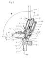
- FIGS. 3 to 6 show a somewhat modified embodiment of the valve 1 and 2.
- FIGS. 3 to 6 are all the items with the same Reference numerals referred to as in Fig. 1 and 2, but with an apostrophe Mistake.
- the basic structure of the valve is the same as in the embodiment of FIGS. 1 and 2 and will therefore not be repeated explained.
- the difference between the two embodiments is that in the valve according to FIGS. 3 and 4, the central axis M1 of the magnet system 4 'and valve chamber 1.1' from the vertical deviating from the central axis M2 of the inlet channel 2 'forms a predetermined obtuse angle ⁇ . Thereby the valve appears tilted towards the inlet channel 2 ', so that, as can be seen directly from Fig.
- FIG. 6 is the more accurate training on the upper inner wall part 2.1 'of the inlet channel 2' to recognize.
- This upper inner wall part 2.1 ' has in the inner region, ie in the vicinity of the confluence point 2.3 'in the Valve chamber 1.1 ', a deviating from the circular shape flatter curvature as in the outer area.
- the groove 2.2 ' arranged with a V-shaped cross section through which the air or Steam bubbles are discharged to the outside.
- the solenoid valve it may be advantageous be, at least the upper inner wall part 2.1 or 2.1 'of the inlet channel and / or the inner surface of the separation membrane 8.1 or 8.1 'in the already described manner with a substance to coat the surface Hydrophobicity and a self-cleaning effect structuring in the nanometer range.
Landscapes
- Engineering & Computer Science (AREA)
- General Engineering & Computer Science (AREA)
- Mechanical Engineering (AREA)
- Magnetically Actuated Valves (AREA)
- Temperature-Responsive Valves (AREA)
- Multiple-Way Valves (AREA)
- Lift Valve (AREA)
Applications Claiming Priority (2)
| Application Number | Priority Date | Filing Date | Title |
|---|---|---|---|
| DE102004023117 | 2004-05-11 | ||
| DE200410023117 DE102004023117A1 (de) | 2004-05-11 | 2004-05-11 | Elektromagnetventil für flüssige Medien, insbesondere Heißwasser |
Publications (2)
| Publication Number | Publication Date |
|---|---|
| EP1596109A1 true EP1596109A1 (fr) | 2005-11-16 |
| EP1596109B1 EP1596109B1 (fr) | 2007-03-14 |
Family
ID=34935858
Family Applications (1)
| Application Number | Title | Priority Date | Filing Date |
|---|---|---|---|
| EP20050009283 Active EP1596109B1 (fr) | 2004-05-11 | 2005-04-28 | Soupape électromagnétique pour fluides, notamment eau chaude |
Country Status (5)
| Country | Link |
|---|---|
| US (1) | US7383854B2 (fr) |
| EP (1) | EP1596109B1 (fr) |
| AT (1) | ATE356951T1 (fr) |
| DE (2) | DE102004023117A1 (fr) |
| DK (1) | DK1596109T3 (fr) |
Cited By (3)
| Publication number | Priority date | Publication date | Assignee | Title |
|---|---|---|---|---|
| EP1936248A2 (fr) | 2006-12-20 | 2008-06-25 | A. u. K. Müller GmbH & Co. KG | Ventilateur électromagnétique pour milieux liquides et gazeux |
| EP2093466A3 (fr) * | 2008-02-22 | 2009-11-04 | Gruppo Bertolaso S.p.A. | Vanne |
| EP3070381A1 (fr) * | 2015-03-20 | 2016-09-21 | Gemü Gebr. Müller Apparatebau Gmbh & Co. Kommanditgesellschaf | Élement de fermeture d'un dispositif de soupape |
Families Citing this family (10)
| Publication number | Priority date | Publication date | Assignee | Title |
|---|---|---|---|---|
| US20090004530A1 (en) * | 2007-06-28 | 2009-01-01 | Christian Koenig | Control valve with enhanced inner surface |
| DE202007012652U1 (de) * | 2007-09-10 | 2007-11-22 | Bürkert Werke GmbH & Co. KG | Magnetventil |
| EP2542806A4 (fr) * | 2010-03-04 | 2014-06-18 | Bio Rad Laboratories | Obturateur à diaphragme |
| CN201764004U (zh) * | 2010-05-14 | 2011-03-16 | 厦门坤锦电子科技有限公司 | 一种高耐腐蚀隔膜阀 |
| US8342479B2 (en) | 2010-12-29 | 2013-01-01 | Shih Shih Technology Co., Ltd. | Solenoid controlled valve for fluid media |
| DE102014222240A1 (de) * | 2014-10-30 | 2016-05-04 | Continental Automotive Gmbh | Ventilvorrichtung für ein Kraftfahrzeug |
| DE102014017548A1 (de) * | 2014-11-28 | 2016-06-02 | Samson Ag | Druckanzeigeeinrichtung |
| CN104633176B (zh) * | 2015-02-12 | 2017-03-15 | 无锡卓尔阀业有限公司 | 自力式减温器 |
| EP3517185A1 (fr) * | 2018-01-29 | 2019-07-31 | Marioff Corporation OY | Ensemble de soupape |
| DE202024106671U1 (de) | 2024-11-19 | 2024-12-04 | A. u. K. Müller GmbH & Co KG. | Magnetventil zum Steuern von Fluidströmen |
Citations (3)
| Publication number | Priority date | Publication date | Assignee | Title |
|---|---|---|---|---|
| US4819691A (en) * | 1986-10-21 | 1989-04-11 | Steridose Systems Ab | Valve device |
| DE10162794A1 (de) * | 2001-12-20 | 2003-07-03 | Mueller A & K Gmbh Co Kg | Elektromagnetventil für flüssige Medien, insbesondere Heisswasser |
| US6648006B1 (en) * | 1999-03-31 | 2003-11-18 | Ostergaard Maskinfabrik A/S | Valve and a method of closing a valve |
Family Cites Families (25)
| Publication number | Priority date | Publication date | Assignee | Title |
|---|---|---|---|---|
| US1951037A (en) * | 1930-06-10 | 1934-03-13 | Cochrane Corp | Blow-off valve |
| US2699801A (en) * | 1949-10-20 | 1955-01-18 | Schleyer Victor | Packingless valve with secondary seal and failure indicator |
| US3134570A (en) * | 1960-05-16 | 1964-05-26 | Saunders Valve Co Ltd | Diaphragm valve |
| US3429552A (en) * | 1965-07-08 | 1969-02-25 | Dole Valve Co | Adjustable rate valve assembly |
| DE2017759A1 (de) * | 1970-04-14 | 1971-10-28 | Daimler Benz Ag | Thermostatgesteuertes Ventil, insbesondere für Motoren von Kraftfahrzeugen |
| US3812398A (en) * | 1972-11-10 | 1974-05-21 | Controls Co Of America | Drain valve |
| US4176686A (en) * | 1977-11-19 | 1979-12-04 | Concordia Fluidtechnik Gmbh | Flow control valve for liquids |
| EP0035605B1 (fr) * | 1980-03-10 | 1985-09-04 | BBC Aktiengesellschaft Brown, Boveri & Cie. | Organe de fermeture pour milieux gazeux avec un dispositif pour amortir des vibrations acoustiques auto-amorçées dans des cavités |
| US4703775A (en) * | 1985-09-16 | 1987-11-03 | Abbott Laboratories | Liquid flow regulator |
| US4915353A (en) * | 1988-09-26 | 1990-04-10 | Nupro Company | Diaphragm valve |
| AT396622B (de) * | 1990-02-19 | 1993-10-25 | Avl Verbrennungskraft Messtech | Elektromagnetisch betätigbares ventil |
| DE4142130A1 (de) * | 1991-12-20 | 1993-06-24 | Basf Ag | Verwendung von polyacetalen auf basis von vinylethern und dihydroxyverbindungen in wasch- und reinigungsmitteln und polyacetale |
| JP3355254B2 (ja) * | 1994-09-26 | 2002-12-09 | エヌオーケー株式会社 | ダイアフラムバルブ |
| US5811510A (en) * | 1995-04-14 | 1998-09-22 | General Hospital Corporation | Biodegradable polyacetal polymers and methods for their formation and use |
| DE19983651B4 (de) * | 1998-10-15 | 2008-04-10 | Kabushiki Kaisha Fujikin | Fluidsteuerung |
| DE19852411A1 (de) * | 1998-11-13 | 2000-05-18 | Grohe Kg Hans | Wasserstrahlbelüfter |
| CA2453050A1 (fr) * | 2000-09-06 | 2002-03-14 | A.P. Pharma, Inc. | Polymeres degradables de polyacetal |
| US20030120355A1 (en) * | 2001-06-08 | 2003-06-26 | Urs Hafeli | Biocompatible and biodegradable polymers for diagnostic and therapeutic radioisotope delivery |
| AU2002348703B2 (en) * | 2001-10-29 | 2007-10-11 | Bermad, Limited Partnership | Roll diaphragm control valve |
| JP4310532B2 (ja) * | 2002-11-27 | 2009-08-12 | Smc株式会社 | 流量調整弁 |
| US6878374B2 (en) * | 2003-02-25 | 2005-04-12 | Nitto Denko Corporation | Biodegradable polyacetals |
| US7332477B2 (en) * | 2003-07-10 | 2008-02-19 | Nitto Denko Corporation | Photocleavable DNA transfer agent |
| US7048925B2 (en) * | 2003-08-28 | 2006-05-23 | Nitto Denko Corporation | Acid-sensitive polyacetals and methods |
| EP1667732B1 (fr) * | 2003-09-29 | 2010-04-21 | Nitto Denko Corporation | Polyacetals biodegradables pour administration de polynucleotides in vivo |
| CA2453481A1 (fr) * | 2003-12-17 | 2005-06-17 | Alex Woo | Robinet de dispositif d'alimentation automatique en eau actionne par infrarouge |
-
2004
- 2004-05-11 DE DE200410023117 patent/DE102004023117A1/de not_active Withdrawn
-
2005
- 2005-04-28 DE DE200550000465 patent/DE502005000465D1/de active Active
- 2005-04-28 EP EP20050009283 patent/EP1596109B1/fr active Active
- 2005-04-28 AT AT05009283T patent/ATE356951T1/de not_active IP Right Cessation
- 2005-04-28 DK DK05009283T patent/DK1596109T3/da active
- 2005-05-11 US US11/126,876 patent/US7383854B2/en not_active Expired - Fee Related
Patent Citations (4)
| Publication number | Priority date | Publication date | Assignee | Title |
|---|---|---|---|---|
| US4819691A (en) * | 1986-10-21 | 1989-04-11 | Steridose Systems Ab | Valve device |
| US4819691B1 (en) * | 1986-10-21 | 1997-09-23 | Steridose Systems Ab | Valve device |
| US6648006B1 (en) * | 1999-03-31 | 2003-11-18 | Ostergaard Maskinfabrik A/S | Valve and a method of closing a valve |
| DE10162794A1 (de) * | 2001-12-20 | 2003-07-03 | Mueller A & K Gmbh Co Kg | Elektromagnetventil für flüssige Medien, insbesondere Heisswasser |
Cited By (5)
| Publication number | Priority date | Publication date | Assignee | Title |
|---|---|---|---|---|
| EP1936248A2 (fr) | 2006-12-20 | 2008-06-25 | A. u. K. Müller GmbH & Co. KG | Ventilateur électromagnétique pour milieux liquides et gazeux |
| EP1936248A3 (fr) * | 2006-12-20 | 2009-12-02 | A. u. K. Müller GmbH & Co. KG | Ventilateur électromagnétique pour milieux liquides et gazeux |
| EP2093466A3 (fr) * | 2008-02-22 | 2009-11-04 | Gruppo Bertolaso S.p.A. | Vanne |
| EP3070381A1 (fr) * | 2015-03-20 | 2016-09-21 | Gemü Gebr. Müller Apparatebau Gmbh & Co. Kommanditgesellschaf | Élement de fermeture d'un dispositif de soupape |
| DE102015205127A1 (de) * | 2015-03-20 | 2016-09-22 | Gemü Gebr. Müller Apparatebau Gmbh & Co. Kommanditgesellschaft | Verschlusselement für eine Ventileinrichtung |
Also Published As
| Publication number | Publication date |
|---|---|
| DK1596109T3 (da) | 2007-07-16 |
| US7383854B2 (en) | 2008-06-10 |
| ATE356951T1 (de) | 2007-04-15 |
| DE102004023117A1 (de) | 2005-12-08 |
| DE502005000465D1 (de) | 2007-04-26 |
| US20050254973A1 (en) | 2005-11-17 |
| EP1596109B1 (fr) | 2007-03-14 |
Similar Documents
| Publication | Publication Date | Title |
|---|---|---|
| EP1596109B1 (fr) | Soupape électromagnétique pour fluides, notamment eau chaude | |
| DE602004007356T2 (de) | Ventil und verfahren zur bereitstellung eines fluidimpulses | |
| DE69832042T2 (de) | Absperrfülventil | |
| EP3213803A1 (fr) | Système de filtre | |
| DE69932063T2 (de) | Verbessertes automatisches ablaufventil | |
| DE102011002129A1 (de) | Kupplungskopf mit einem Filterelement | |
| DE2932014A1 (de) | Rueckflusstank | |
| DE60205815T2 (de) | Rückschlagventil und Filtervorrichtung, insbesondere für Wasserkühler | |
| DE2832439A1 (de) | Ringdichtung, insbesondere fuer absperrorgane mit kugelfoermigem absperrkoerper | |
| EP0112977A1 (fr) | Organe d'arrêt pour fluides agressifs | |
| DE8812456U1 (de) | Selbstdichtendes Ventil | |
| DE102010025370A1 (de) | Fluidschaltventil, insbesondere Sitzventil | |
| DE10162794A1 (de) | Elektromagnetventil für flüssige Medien, insbesondere Heisswasser | |
| DE19853118B4 (de) | Ventil | |
| DE102009055118A1 (de) | Magnetventil sowie Fahrerassistenzeinrichtung | |
| DE3540025A1 (de) | Abdichtung fuer eine rotierende, im betrieb aufrecht stehende welle, insbesondere fuer wellen von pumpen und ruehrern | |
| EP4382746A2 (fr) | Unité de pompe à usage médical | |
| EP3658803A1 (fr) | Soupape à double siège ayant une membrane | |
| DE102011015090A1 (de) | Filter | |
| DE102012011943B4 (de) | Volumenstromregler mit einer Venturidüseneinheit, insbesondere aus Kunststoff | |
| EP1286092B1 (fr) | Soupape pour milieux liquides | |
| DE29721109U1 (de) | Hydraulisches Rückschlagventil | |
| DE202010008017U1 (de) | Ventilvorrichtung | |
| DE29808322U1 (de) | Absperrorgan für Fluide | |
| DE202016000514U1 (de) | Absperrarmatur |
Legal Events
| Date | Code | Title | Description |
|---|---|---|---|
| PUAI | Public reference made under article 153(3) epc to a published international application that has entered the european phase |
Free format text: ORIGINAL CODE: 0009012 |
|
| AK | Designated contracting states |
Kind code of ref document: A1 Designated state(s): AT BE BG CH CY CZ DE DK EE ES FI FR GB GR HU IE IS IT LI LT LU MC NL PL PT RO SE SI SK TR |
|
| AX | Request for extension of the european patent |
Extension state: AL BA HR LV MK YU |
|
| 17P | Request for examination filed |
Effective date: 20060511 |
|
| AKX | Designation fees paid |
Designated state(s): AT BE BG CH CY CZ DE DK EE ES FI FR GB GR HU IE IS IT LI LT LU MC NL PL PT RO SE SI SK TR |
|
| GRAP | Despatch of communication of intention to grant a patent |
Free format text: ORIGINAL CODE: EPIDOSNIGR1 |
|
| GRAS | Grant fee paid |
Free format text: ORIGINAL CODE: EPIDOSNIGR3 |
|
| GRAA | (expected) grant |
Free format text: ORIGINAL CODE: 0009210 |
|
| AK | Designated contracting states |
Kind code of ref document: B1 Designated state(s): AT BE BG CH CY CZ DE DK EE ES FI FR GB GR HU IE IS IT LI LT LU MC NL PL PT RO SE SI SK TR |
|
| PG25 | Lapsed in a contracting state [announced via postgrant information from national office to epo] |
Ref country code: SI Free format text: LAPSE BECAUSE OF FAILURE TO SUBMIT A TRANSLATION OF THE DESCRIPTION OR TO PAY THE FEE WITHIN THE PRESCRIBED TIME-LIMIT Effective date: 20070314 Ref country code: PL Free format text: LAPSE BECAUSE OF FAILURE TO SUBMIT A TRANSLATION OF THE DESCRIPTION OR TO PAY THE FEE WITHIN THE PRESCRIBED TIME-LIMIT Effective date: 20070314 Ref country code: FI Free format text: LAPSE BECAUSE OF FAILURE TO SUBMIT A TRANSLATION OF THE DESCRIPTION OR TO PAY THE FEE WITHIN THE PRESCRIBED TIME-LIMIT Effective date: 20070314 Ref country code: IE Free format text: LAPSE BECAUSE OF FAILURE TO SUBMIT A TRANSLATION OF THE DESCRIPTION OR TO PAY THE FEE WITHIN THE PRESCRIBED TIME-LIMIT Effective date: 20070314 |
|
| REG | Reference to a national code |
Ref country code: GB Ref legal event code: FG4D Free format text: NOT ENGLISH |
|
| REG | Reference to a national code |
Ref country code: CH Ref legal event code: EP |
|
| REF | Corresponds to: |
Ref document number: 502005000465 Country of ref document: DE Date of ref document: 20070426 Kind code of ref document: P |
|
| REG | Reference to a national code |
Ref country code: IE Ref legal event code: FG4D Free format text: LANGUAGE OF EP DOCUMENT: GERMAN |
|
| GBT | Gb: translation of ep patent filed (gb section 77(6)(a)/1977) |
Effective date: 20070413 |
|
| PG25 | Lapsed in a contracting state [announced via postgrant information from national office to epo] |
Ref country code: ES Free format text: LAPSE BECAUSE OF FAILURE TO SUBMIT A TRANSLATION OF THE DESCRIPTION OR TO PAY THE FEE WITHIN THE PRESCRIBED TIME-LIMIT Effective date: 20070625 |
|
| REG | Reference to a national code |
Ref country code: SE Ref legal event code: TRGR |
|
| PG25 | Lapsed in a contracting state [announced via postgrant information from national office to epo] |
Ref country code: IS Free format text: LAPSE BECAUSE OF FAILURE TO SUBMIT A TRANSLATION OF THE DESCRIPTION OR TO PAY THE FEE WITHIN THE PRESCRIBED TIME-LIMIT Effective date: 20070714 |
|
| REG | Reference to a national code |
Ref country code: DK Ref legal event code: T3 |
|
| ET | Fr: translation filed | ||
| PG25 | Lapsed in a contracting state [announced via postgrant information from national office to epo] |
Ref country code: PT Free format text: LAPSE BECAUSE OF FAILURE TO SUBMIT A TRANSLATION OF THE DESCRIPTION OR TO PAY THE FEE WITHIN THE PRESCRIBED TIME-LIMIT Effective date: 20070814 |
|
| REG | Reference to a national code |
Ref country code: IE Ref legal event code: FD4D |
|
| PG25 | Lapsed in a contracting state [announced via postgrant information from national office to epo] |
Ref country code: SK Free format text: LAPSE BECAUSE OF FAILURE TO SUBMIT A TRANSLATION OF THE DESCRIPTION OR TO PAY THE FEE WITHIN THE PRESCRIBED TIME-LIMIT Effective date: 20070314 |
|
| BERE | Be: lapsed |
Owner name: A. UND K. MULLER G.M.B.H. & CO. KG Effective date: 20070430 |
|
| PG25 | Lapsed in a contracting state [announced via postgrant information from national office to epo] |
Ref country code: CZ Free format text: LAPSE BECAUSE OF FAILURE TO SUBMIT A TRANSLATION OF THE DESCRIPTION OR TO PAY THE FEE WITHIN THE PRESCRIBED TIME-LIMIT Effective date: 20070314 Ref country code: RO Free format text: LAPSE BECAUSE OF FAILURE TO SUBMIT A TRANSLATION OF THE DESCRIPTION OR TO PAY THE FEE WITHIN THE PRESCRIBED TIME-LIMIT Effective date: 20070314 |
|
| PLBE | No opposition filed within time limit |
Free format text: ORIGINAL CODE: 0009261 |
|
| STAA | Information on the status of an ep patent application or granted ep patent |
Free format text: STATUS: NO OPPOSITION FILED WITHIN TIME LIMIT |
|
| 26N | No opposition filed |
Effective date: 20071217 |
|
| PG25 | Lapsed in a contracting state [announced via postgrant information from national office to epo] |
Ref country code: LT Free format text: LAPSE BECAUSE OF FAILURE TO SUBMIT A TRANSLATION OF THE DESCRIPTION OR TO PAY THE FEE WITHIN THE PRESCRIBED TIME-LIMIT Effective date: 20070314 Ref country code: BE Free format text: LAPSE BECAUSE OF NON-PAYMENT OF DUE FEES Effective date: 20070430 |
|
| PG25 | Lapsed in a contracting state [announced via postgrant information from national office to epo] |
Ref country code: GR Free format text: LAPSE BECAUSE OF FAILURE TO SUBMIT A TRANSLATION OF THE DESCRIPTION OR TO PAY THE FEE WITHIN THE PRESCRIBED TIME-LIMIT Effective date: 20070615 |
|
| PG25 | Lapsed in a contracting state [announced via postgrant information from national office to epo] |
Ref country code: AT Free format text: LAPSE BECAUSE OF NON-PAYMENT OF DUE FEES Effective date: 20070428 |
|
| PG25 | Lapsed in a contracting state [announced via postgrant information from national office to epo] |
Ref country code: EE Free format text: LAPSE BECAUSE OF FAILURE TO SUBMIT A TRANSLATION OF THE DESCRIPTION OR TO PAY THE FEE WITHIN THE PRESCRIBED TIME-LIMIT Effective date: 20070314 |
|
| PG25 | Lapsed in a contracting state [announced via postgrant information from national office to epo] |
Ref country code: MC Free format text: LAPSE BECAUSE OF NON-PAYMENT OF DUE FEES Effective date: 20070430 |
|
| PG25 | Lapsed in a contracting state [announced via postgrant information from national office to epo] |
Ref country code: CY Free format text: LAPSE BECAUSE OF FAILURE TO SUBMIT A TRANSLATION OF THE DESCRIPTION OR TO PAY THE FEE WITHIN THE PRESCRIBED TIME-LIMIT Effective date: 20070314 |
|
| PG25 | Lapsed in a contracting state [announced via postgrant information from national office to epo] |
Ref country code: BG Free format text: LAPSE BECAUSE OF FAILURE TO SUBMIT A TRANSLATION OF THE DESCRIPTION OR TO PAY THE FEE WITHIN THE PRESCRIBED TIME-LIMIT Effective date: 20070614 Ref country code: LU Free format text: LAPSE BECAUSE OF NON-PAYMENT OF DUE FEES Effective date: 20070428 |
|
| PGFP | Annual fee paid to national office [announced via postgrant information from national office to epo] |
Ref country code: FR Payment date: 20090429 Year of fee payment: 5 |
|
| PG25 | Lapsed in a contracting state [announced via postgrant information from national office to epo] |
Ref country code: HU Free format text: LAPSE BECAUSE OF FAILURE TO SUBMIT A TRANSLATION OF THE DESCRIPTION OR TO PAY THE FEE WITHIN THE PRESCRIBED TIME-LIMIT Effective date: 20070915 Ref country code: TR Free format text: LAPSE BECAUSE OF FAILURE TO SUBMIT A TRANSLATION OF THE DESCRIPTION OR TO PAY THE FEE WITHIN THE PRESCRIBED TIME-LIMIT Effective date: 20070314 |
|
| REG | Reference to a national code |
Ref country code: CH Ref legal event code: PL |
|
| PG25 | Lapsed in a contracting state [announced via postgrant information from national office to epo] |
Ref country code: CH Free format text: LAPSE BECAUSE OF NON-PAYMENT OF DUE FEES Effective date: 20090430 Ref country code: LI Free format text: LAPSE BECAUSE OF NON-PAYMENT OF DUE FEES Effective date: 20090430 |
|
| REG | Reference to a national code |
Ref country code: FR Ref legal event code: ST Effective date: 20101230 |
|
| PGFP | Annual fee paid to national office [announced via postgrant information from national office to epo] |
Ref country code: SE Payment date: 20110420 Year of fee payment: 7 |
|
| PGFP | Annual fee paid to national office [announced via postgrant information from national office to epo] |
Ref country code: DK Payment date: 20110420 Year of fee payment: 7 |
|
| PG25 | Lapsed in a contracting state [announced via postgrant information from national office to epo] |
Ref country code: FR Free format text: LAPSE BECAUSE OF NON-PAYMENT OF DUE FEES Effective date: 20100430 |
|
| REG | Reference to a national code |
Ref country code: DK Ref legal event code: EBP |
|
| REG | Reference to a national code |
Ref country code: SE Ref legal event code: EUG |
|
| PG25 | Lapsed in a contracting state [announced via postgrant information from national office to epo] |
Ref country code: SE Free format text: LAPSE BECAUSE OF NON-PAYMENT OF DUE FEES Effective date: 20120429 |
|
| PG25 | Lapsed in a contracting state [announced via postgrant information from national office to epo] |
Ref country code: DK Free format text: LAPSE BECAUSE OF NON-PAYMENT OF DUE FEES Effective date: 20120430 |
|
| PGFP | Annual fee paid to national office [announced via postgrant information from national office to epo] |
Ref country code: GB Payment date: 20150423 Year of fee payment: 11 |
|
| PGFP | Annual fee paid to national office [announced via postgrant information from national office to epo] |
Ref country code: IT Payment date: 20160422 Year of fee payment: 12 |
|
| GBPC | Gb: european patent ceased through non-payment of renewal fee |
Effective date: 20160428 |
|
| PG25 | Lapsed in a contracting state [announced via postgrant information from national office to epo] |
Ref country code: GB Free format text: LAPSE BECAUSE OF NON-PAYMENT OF DUE FEES Effective date: 20160428 |
|
| PGFP | Annual fee paid to national office [announced via postgrant information from national office to epo] |
Ref country code: NL Payment date: 20170424 Year of fee payment: 13 |
|
| PG25 | Lapsed in a contracting state [announced via postgrant information from national office to epo] |
Ref country code: IT Free format text: LAPSE BECAUSE OF NON-PAYMENT OF DUE FEES Effective date: 20170428 |
|
| REG | Reference to a national code |
Ref country code: NL Ref legal event code: MM Effective date: 20180501 |
|
| PG25 | Lapsed in a contracting state [announced via postgrant information from national office to epo] |
Ref country code: NL Free format text: LAPSE BECAUSE OF NON-PAYMENT OF DUE FEES Effective date: 20180501 |
|
| P01 | Opt-out of the competence of the unified patent court (upc) registered |
Effective date: 20230519 |
|
| PGFP | Annual fee paid to national office [announced via postgrant information from national office to epo] |
Ref country code: DE Payment date: 20240430 Year of fee payment: 20 |