EP1539649B1 - Inorganic matrix-fabric system and method - Google Patents
Inorganic matrix-fabric system and method Download PDFInfo
- Publication number
- EP1539649B1 EP1539649B1 EP03772070.3A EP03772070A EP1539649B1 EP 1539649 B1 EP1539649 B1 EP 1539649B1 EP 03772070 A EP03772070 A EP 03772070A EP 1539649 B1 EP1539649 B1 EP 1539649B1
- Authority
- EP
- European Patent Office
- Prior art keywords
- wall
- glass
- fibrous layer
- coating
- reinforcement
- Prior art date
- Legal status (The legal status is an assumption and is not a legal conclusion. Google has not performed a legal analysis and makes no representation as to the accuracy of the status listed.)
- Expired - Lifetime
Links
Images


Classifications
-
- E—FIXED CONSTRUCTIONS
- E04—BUILDING
- E04G—SCAFFOLDING; FORMS; SHUTTERING; BUILDING IMPLEMENTS OR AIDS, OR THEIR USE; HANDLING BUILDING MATERIALS ON THE SITE; REPAIRING, BREAKING-UP OR OTHER WORK ON EXISTING BUILDINGS
- E04G23/00—Working measures on existing buildings
- E04G23/02—Repairing, e.g. filling cracks; Restoring; Altering; Enlarging
- E04G23/0218—Increasing or restoring the load-bearing capacity of building construction elements
-
- B—PERFORMING OPERATIONS; TRANSPORTING
- B32—LAYERED PRODUCTS
- B32B—LAYERED PRODUCTS, i.e. PRODUCTS BUILT-UP OF STRATA OF FLAT OR NON-FLAT, e.g. CELLULAR OR HONEYCOMB, FORM
- B32B17/00—Layered products essentially comprising sheet glass, or glass, slag, or like fibres
- B32B17/02—Layered products essentially comprising sheet glass, or glass, slag, or like fibres in the form of fibres or filaments
- B32B17/04—Layered products essentially comprising sheet glass, or glass, slag, or like fibres in the form of fibres or filaments bonded with or embedded in a plastic substance
-
- C—CHEMISTRY; METALLURGY
- C03—GLASS; MINERAL OR SLAG WOOL
- C03C—CHEMICAL COMPOSITION OF GLASSES, GLAZES OR VITREOUS ENAMELS; SURFACE TREATMENT OF GLASS; SURFACE TREATMENT OF FIBRES OR FILAMENTS MADE FROM GLASS, MINERALS OR SLAGS; JOINING GLASS TO GLASS OR OTHER MATERIALS
- C03C25/00—Surface treatment of fibres or filaments made from glass, minerals or slags
- C03C25/10—Coating
- C03C25/1025—Coating to obtain fibres used for reinforcing cement-based products
- C03C25/103—Organic coatings
-
- C—CHEMISTRY; METALLURGY
- C03—GLASS; MINERAL OR SLAG WOOL
- C03C—CHEMICAL COMPOSITION OF GLASSES, GLAZES OR VITREOUS ENAMELS; SURFACE TREATMENT OF GLASS; SURFACE TREATMENT OF FIBRES OR FILAMENTS MADE FROM GLASS, MINERALS OR SLAGS; JOINING GLASS TO GLASS OR OTHER MATERIALS
- C03C25/00—Surface treatment of fibres or filaments made from glass, minerals or slags
- C03C25/10—Coating
- C03C25/1095—Coating to obtain coated fabrics
-
- C—CHEMISTRY; METALLURGY
- C04—CEMENTS; CONCRETE; ARTIFICIAL STONE; CERAMICS; REFRACTORIES
- C04B—LIME, MAGNESIA; SLAG; CEMENTS; COMPOSITIONS THEREOF, e.g. MORTARS, CONCRETE OR LIKE BUILDING MATERIALS; ARTIFICIAL STONE; CERAMICS; REFRACTORIES; TREATMENT OF NATURAL STONE
- C04B28/00—Compositions of mortars, concrete or artificial stone, containing inorganic binders or the reaction product of an inorganic and an organic binder, e.g. polycarboxylate cements
- C04B28/02—Compositions of mortars, concrete or artificial stone, containing inorganic binders or the reaction product of an inorganic and an organic binder, e.g. polycarboxylate cements containing hydraulic cements other than calcium sulfates
-
- E—FIXED CONSTRUCTIONS
- E04—BUILDING
- E04G—SCAFFOLDING; FORMS; SHUTTERING; BUILDING IMPLEMENTS OR AIDS, OR THEIR USE; HANDLING BUILDING MATERIALS ON THE SITE; REPAIRING, BREAKING-UP OR OTHER WORK ON EXISTING BUILDINGS
- E04G23/00—Working measures on existing buildings
- E04G23/02—Repairing, e.g. filling cracks; Restoring; Altering; Enlarging
- E04G23/0218—Increasing or restoring the load-bearing capacity of building construction elements
- E04G2023/0251—Increasing or restoring the load-bearing capacity of building construction elements by using fiber reinforced plastic elements
-
- Y—GENERAL TAGGING OF NEW TECHNOLOGICAL DEVELOPMENTS; GENERAL TAGGING OF CROSS-SECTIONAL TECHNOLOGIES SPANNING OVER SEVERAL SECTIONS OF THE IPC; TECHNICAL SUBJECTS COVERED BY FORMER USPC CROSS-REFERENCE ART COLLECTIONS [XRACs] AND DIGESTS
- Y10—TECHNICAL SUBJECTS COVERED BY FORMER USPC
- Y10T—TECHNICAL SUBJECTS COVERED BY FORMER US CLASSIFICATION
- Y10T156/00—Adhesive bonding and miscellaneous chemical manufacture
- Y10T156/10—Methods of surface bonding and/or assembly therefor
-
- Y—GENERAL TAGGING OF NEW TECHNOLOGICAL DEVELOPMENTS; GENERAL TAGGING OF CROSS-SECTIONAL TECHNOLOGIES SPANNING OVER SEVERAL SECTIONS OF THE IPC; TECHNICAL SUBJECTS COVERED BY FORMER USPC CROSS-REFERENCE ART COLLECTIONS [XRACs] AND DIGESTS
- Y10—TECHNICAL SUBJECTS COVERED BY FORMER USPC
- Y10T—TECHNICAL SUBJECTS COVERED BY FORMER US CLASSIFICATION
- Y10T29/00—Metal working
- Y10T29/49—Method of mechanical manufacture
- Y10T29/49616—Structural member making
- Y10T29/49618—Restoring existing member, e.g., reinforcing, repairing
-
- Y—GENERAL TAGGING OF NEW TECHNOLOGICAL DEVELOPMENTS; GENERAL TAGGING OF CROSS-SECTIONAL TECHNOLOGIES SPANNING OVER SEVERAL SECTIONS OF THE IPC; TECHNICAL SUBJECTS COVERED BY FORMER USPC CROSS-REFERENCE ART COLLECTIONS [XRACs] AND DIGESTS
- Y10—TECHNICAL SUBJECTS COVERED BY FORMER USPC
- Y10T—TECHNICAL SUBJECTS COVERED BY FORMER US CLASSIFICATION
- Y10T428/00—Stock material or miscellaneous articles
- Y10T428/249921—Web or sheet containing structurally defined element or component
- Y10T428/249924—Noninterengaged fiber-containing paper-free web or sheet which is not of specified porosity
- Y10T428/249928—Fiber embedded in a ceramic, glass, or carbon matrix
- Y10T428/249929—Fibers are aligned substantially parallel
-
- Y—GENERAL TAGGING OF NEW TECHNOLOGICAL DEVELOPMENTS; GENERAL TAGGING OF CROSS-SECTIONAL TECHNOLOGIES SPANNING OVER SEVERAL SECTIONS OF THE IPC; TECHNICAL SUBJECTS COVERED BY FORMER USPC CROSS-REFERENCE ART COLLECTIONS [XRACs] AND DIGESTS
- Y10—TECHNICAL SUBJECTS COVERED BY FORMER USPC
- Y10T—TECHNICAL SUBJECTS COVERED BY FORMER US CLASSIFICATION
- Y10T428/00—Stock material or miscellaneous articles
- Y10T428/249921—Web or sheet containing structurally defined element or component
- Y10T428/249924—Noninterengaged fiber-containing paper-free web or sheet which is not of specified porosity
- Y10T428/249932—Fiber embedded in a layer derived from a water-settable material [e.g., cement, gypsum, etc.]
-
- Y—GENERAL TAGGING OF NEW TECHNOLOGICAL DEVELOPMENTS; GENERAL TAGGING OF CROSS-SECTIONAL TECHNOLOGIES SPANNING OVER SEVERAL SECTIONS OF THE IPC; TECHNICAL SUBJECTS COVERED BY FORMER USPC CROSS-REFERENCE ART COLLECTIONS [XRACs] AND DIGESTS
- Y10—TECHNICAL SUBJECTS COVERED BY FORMER USPC
- Y10T—TECHNICAL SUBJECTS COVERED BY FORMER US CLASSIFICATION
- Y10T428/00—Stock material or miscellaneous articles
- Y10T428/249921—Web or sheet containing structurally defined element or component
- Y10T428/249924—Noninterengaged fiber-containing paper-free web or sheet which is not of specified porosity
- Y10T428/24994—Fiber embedded in or on the surface of a polymeric matrix
- Y10T428/249942—Fibers are aligned substantially parallel
- Y10T428/249946—Glass fiber
-
- Y—GENERAL TAGGING OF NEW TECHNOLOGICAL DEVELOPMENTS; GENERAL TAGGING OF CROSS-SECTIONAL TECHNOLOGIES SPANNING OVER SEVERAL SECTIONS OF THE IPC; TECHNICAL SUBJECTS COVERED BY FORMER USPC CROSS-REFERENCE ART COLLECTIONS [XRACs] AND DIGESTS
- Y10—TECHNICAL SUBJECTS COVERED BY FORMER USPC
- Y10T—TECHNICAL SUBJECTS COVERED BY FORMER US CLASSIFICATION
- Y10T428/00—Stock material or miscellaneous articles
- Y10T428/249921—Web or sheet containing structurally defined element or component
- Y10T428/249924—Noninterengaged fiber-containing paper-free web or sheet which is not of specified porosity
- Y10T428/24994—Fiber embedded in or on the surface of a polymeric matrix
- Y10T428/249948—Fiber is precoated
Definitions
- This invention relates to a method for strengthening of structural supports.
- Walls, columns and other structures constructed of materials such as concrete or cement paste, brick or masonry units, and the like are widely used as support structures. Tunnels, building structural supports, bridge supports, freeway overpass supports and parking structure supports are just a few of the many uses for these cementitious structural supports. These supports may exist in a wide variety of shapes with circular, square and rectangular cross-sections being the most common. However, numerous other cross-sectional shapes have been used, including regular polygonal shapes and irregular cross-sections. The size of structural supports also varies greatly depending upon the intended use.
- Structural supports having heights and lengths exceeding 15.24m (50 feet) are commonly used in various applications.
- One way of increasing the structural integrity of support structures is to include additional metal reinforcement prior to forming the structural support.
- Other design features may be incorporated into the support structure fabrication in order to increase its resistance to asymmetric loading or horizontal displacement.
- a composite reinforcement layer having at least one fabric layer located within a resin matrix is wrapped around the exterior surface of a concrete column.
- the fabric layer has first and second parallel selvedges that extend around the circumferential outer surface of the column in a direction substantially perpendicular to the column axis.
- Preferred fibers disclosed by Isley include ones made from glass, polyaramid, graphite, silica, quartz, carbon, ceramic and polyethylene.
- Suitable resins suggested by this patent include polyester, epoxy, polyamide, bismaleimide, vinylester, urethanes, and polyurea, with epoxy-based resins being preferred.
- Reinforcing FRP systems such as those described above can often be flammable, toxic and difficult to handle during application. They also provide, after curing, poor fire resistance, poor bonding to the concrete or brick being reinforced, and poor water/air permeability, resulting in the creation of moisture accumulation. Additionally, they are fairly expensive and tend to delaminate upon failure.
- a repair or reinforcement system for existing support structures or for new construction support structures is needed.
- EP 1 063 366 (Weber Broutin ) describes a method for reinforcing a structural support having the precharacterizing features of claim 1.
- AR-glass Unlike other types of glass fibers, such as E-glass, AR-glass has a high degree of resistance to alkali attack and higher strength retention over time. This is due to the presence of an optimum level of Zirconia (ZrO 2 ) in the glass fibers. This type of glass exhibits a high degree of chemical resistance, resisting the very high alkalinity produced by the hydration of conventional cementitious materials such as ordinary Portland cement.
- ZrO 2 Zirconia
- the preferred cementious material matrix is comprised of material such as cement, concrete or mortar. More preferably the cementious material matrix comprises ordinary Portland cement having chopped reinforcing fibers dispersed throughout the cement. Such fibers may include those made from carbon, AR-glass, cellulose, rayon or polymeric materials, such as aramids, polyolefins, polyester, or hybrids thereof, for example.
- a reinforcement system and a method of reinforcing a structural support using the reinforcement system of the present invention are provided.
- the reinforcement system has improved bonding with a cementitious support structure and is less likely to delaminate from the structural support than existing reinforcement systems.
- Adhesive bonded crossed laid fibers/mesh consisting of layers of parallel textile yarns superimposed on each other at acute or right angles. These layers are bonded at the intersections of the yarns by an adhesive, glue or by thermal bonding.
- Cementitious material/composite Cementitious material/composite.
- An inorganic hydraulically setting material such as those containing portland cement, mortar, plaster, fly ash, slag, silica fume, metakaolin, gypsum, geopolymer and/or other ingredients, such as aggregate, including sand or gravel, additives or admixtures, such as foaming agents, resins, including acrylic fortifiers, moisture resistant additives, shrinkage reducing admixtures (SRA), air-entraining (AE) admixtures, fire retardants, and chopped fibers, including glass, PVA, polypropylene, cellulose, graphite, or hybrids thereof.
- additives or admixtures such as foaming agents, resins, including acrylic fortifiers, moisture resistant additives, shrinkage reducing admixtures (SRA), air-entraining (AE) admixtures, fire retardants, and chopped fibers, including glass, PVA, polypropylene, cellulose, graphite,
- Coatings/binders/finishes Compounds, generally organic, applied to fabrics after processing (e.g., weaving or knitting) to protect the fibers and give the fabric stability.
- Fiber A general term used to refer to filamentary materials. Often, fiber is used synonymously with filament. It is generally accepted that a filament routinely has a finite length that is at least 100 times its diameter. In most cases, it is prepared by drawing from a molten bath, spinning, or by deposition on a substrate.
- Filament The smallest unit of a fibrous material. The basic units formed during drawing and spinning, which are gathered into strands of fiber for use in composites. Filaments usually are of extreme length and very small diameter. Some textile filaments can function as a yarn when they are of sufficient strength and flexibility.
- Glass fiber A fiber spun from an inorganic product of fusion that has cooled to a rigid condition without crystallizing.
- Glass Filament A form of glass that has been drawn to a small diameter and long lengths.
- a matrix material comprising mostly inorganic ingredients, such as ceramics, glasses, cementitious materials, and geopolymers (inorganic resins), for example.
- Knitted fabrics Fabrics produced by interlooping chains of filaments, roving or yarn.
- Mat A fibrous material consisting of randomly oriented chopped filaments, short fibers, or swirled filaments loosely held together with a binder.
- Roving A number of continuous filaments, strands, or collected into a parallel bundle.
- Sizing Compounds, generally organic, applied as a fine coating to rovings after drawing of glass filaments in order to bind the individual filaments together and stiffen them to provide abrasion resistance during processing (e.g., weaving or knitting).
- Tensile strength The maximum load or force per unit cross-sectional area, within the gage length, of the specimen. The pulling stress required to break a given specimen.
- Tex. A unit for expressing linear density (or gauge) equal to the weight in grams of 1 kilometer of yarn, filament, fiber or other textile strand.
- Warp The yarn, fiber or roving running lengthwise in a woven fabric.
- Warp knit is a type of knitting in which the yarns generally run lengthwise in the fabric.
- Weave The particular manner in which a fabric is formed by interlacing yarns, fibers or roving. Weave can be further defined by "type of weave", such as leno weave, for example.
- Woven fabric A material (usually a planar structure) constructed by interlacing yarns, fibers, roving or filaments, to form such fabric patterns as plain, harness satin, or leno weaves.
- Yarn An assemblage of filaments, fibers, or strands, either natural or manufactured, to form a continuous length that is suitable for use in knitting, weaving or interweaving into textile materials.
- the assemblage of filaments, fibers or strands may have some or no twist.
- a reinforcement system 10 is shown reinforcing a support structure 20.
- the present invention may be used to reinforce a wide variety of support structures.
- Such support structures may include, for example, walls, beams, exterior insulation fabric systems ("EIFS”) slabs, chimneys, stacks, tanks, columns, silos, shafts, pipes, conduits, tunnels and the like.
- the support structure may be planar, circular, or any other shape.
- the invention is especially well suited for reinforcing support structures comprised of cementitious or masonry materials such as cement, concrete, brick, and cinder block, which may be reinforced or unreinforced.
- One structural support especially suited for the reinforcement system of the present invention is unreinforced masonry (URM) walls.
- the reinforcement system 10 comprises at least one alkali-resistant open fibrous layer 12 (two fibrous layers are shown in FIG. 1 ) and an inorganic matrix 14.
- the fibrous layers 12 are embedded within the matrix 14.
- the system 10 is applied to a surface of the support structure 20.
- the reinforcement system of the present invention may be applied to an outside surface and an inside surface of a wall of a building, pipe, wall or other structure.
- the inorganic matrix 14 preferably comprises a cementitious material, such as cement paste, mortar or concrete, and/or other types of materials such as gypsum and geopolymers (inorganic resins). More preferably the inorganic matrix comprises Portland cement having chopped fibers dispersed throughout the cement. Preferably the fibers are AR-glass fibers but may also include, for example, other types of glass fibers, aramids, polyolefins, carbon, graphite, polyester, PVA, polypropylene, natural fibers, cellulosic fibers, rayon, and hybrids thereof.
- a cementitious material such as cement paste, mortar or concrete, and/or other types of materials such as gypsum and geopolymers (inorganic resins). More preferably the inorganic matrix comprises Portland cement having chopped fibers dispersed throughout the cement.
- the fibers are AR-glass fibers but may also include, for example, other types of glass fibers, aramids, polyolefins, carbon, graphit
- the inorganic matrix may include other ingredients or additives such as fly ash, latex, slag and metakaolin, resins, such as acrylics, polyvinyl acetate, or the like, ceramics, including silicon oxide, titanium oxide, and silicon nitrite, setting accelerators, water and/or fire resistant additives, such as silioxane, borax, fillers, setting retardants, dispersing agents, dyes and colorants, light stabilizers and heat stabilizers, shrinkage reducing admixtures, air entraining agents, or combinations thereof, for example.
- the inorganic matrix includes a resin that may form an adhesive bond with a resinous coating applied to the alkali-resistant open fibrous layer.
- the inorganic matrix has good bonding with the support structure.
- Portland cement for example, has excellent bonding to concrete, bricks and concrete masonry units (CMUs).
- the inorganic matrix may contain curing agents or other additives such as coloring agents, light stabilizers and heat stabilizers, for example.
- One inner surface 16 of the inorganic matrix is preferably in direct contact with a surface 22 of the support structure. Due to the preferred compatibility of the inorganic matrix 14 with the support structure 20, there is no requirement that any adhesive material be applied between the two materials, however the addition of an adhesive between, or among, the inorganic matrix and the support structure is not precluded.
- the alkali-resistant fibrous layers 12 are a reinforcement material for the inorganic matrix 14.
- the fibrous layers 12 preferably provide long term durability to the reinforcement system 10 in the highly alkaline environment of the inorganic matrix where the matrix is comprised of materials such as cement paste, mortar, or concrete or geopolymers.
- the fibrous layers may be comprised of glass fibers, PVA fibers, carbon fibers or aramid fibers, for example, or any combination thereof.
- the fibrous layers are comprised of AR-glass (alkali-resistant glass), such as that manufactured by Saint Gobain Vetrotex under the trademark Cem-FIL®.
- AR-glass has a high degree of resistance to alkali attack and a higher strength retention over time. This is due to the presence of an optimum level of Zirconia (ZrO 2 ), e.g. preferably about 10% to about 25% ZrO 2 , in the glass fibers. This type of glass exhibits a high degree of chemical resistance, resisting the very high alkalinity produced by the hydration of cementitious materials such as ordinary Portland cement.
- ZrO 2 Zirconia
- AR-glass has superior strengthening properties necessary for use in earthquake and explosion-resistant applications. It has high tensile strength and modulus and does not rust.
- glass fibers such as E-glass, ECR-glass, C-glass, S-glass and A-glass, which are not inherently alkali-resistant, when such fibers are coated with an alkali-resistant material, such as polyvinyl chloride resinous coating.
- the preferred AR-glass fibers are preferably produced as rovings or yarns.
- the linear density of the AR-glass fibers preferably ranges from about 76 Tex where yarns are employed to 2,500 tex where rovings are employed. Where carbon fibers are used, they are preferably provided as tows, with the filament count preferably ranging from about 3,000 to 24,000.
- Preferred properties of the AR-glass include a virgin filament tensile strength of at least about 1275.53 MPa (185,000 psi) or higher, Young's modulus of elasticity of about 68947 to 82737 MPa (10-12 million psi), train at breaking point of at least about 1.5% or higher, water uptake at less than about 0.1%, and softening temperature of about 860°C.
- the fibrous layers 12 may be formed, for example, by various methods of weaving, such as plain or leno weave, or by knitting or laying of continuous fibers.
- the fibrous layers may also be laid scrim or be formed from discontinuous or continuous fibers randomly oriented In a non-woven mat.
- the fibrous layers 12a and 12b are glass fiber bi-directional fibrous layers having two rovings per inch of fibers in one direction (e.g., the weft or fill direction) and one roving per inch of fiber in a direction 90 degrees from the other direction (e.g., the warp direction).
- the glass fiber bi-directional fibrous layers have one roving per inch in each direction.
- Varying fiber orientation, concentration, and fiber type permits tailoring of strength to a specific application. Using different methods of knitting, braiding or weaving of the fabric may also be employed to produce a stronger reinforcement.
- the openings 18 in the fibrous layer 12 should be sufficient to allow interfacing between the layers 14a-c of the inorganic matrix 14 disposed on each side of the fibrous layers 12a and 12b.
- the fibrous layer also preferably includes a sizing.
- Preferred sizings for use with a fibrous layer comprised of AR-glass include aqueous sizings comprising one of the following blends: 1) an epoxy polymer, vinyl and amine coupling agents and a non-ionic surfactant; 2) an epoxy polymer, amine coupling agent and a non-ionic surfactant; 3) an epoxy polymer, metacrylic and epoxy coupling agents, and cationic and non-ionic surfactants (paraffin lubricants); 4) anhydrous polymerized acrylate amine (for example, the substance disclosed in PCT Patent Application No.
- WO 99/31025 which is incorporated herein by reference
- metacrylic and epoxy coupling agents and a non-ionic surfactant metacrylic and epoxy coupling agents and a non-ionic surfactant
- anhydrous polymerized epoxy amine for example, as disclosed in U.S. Patent No. 5,961,684 to Moireau et al. , which is incorporated herein by reference
- vinyl and amine coupling agents, and a non-ionic surfactant each of the above blends being produced by Cem FIL Reinforcements of Saint Gobain Vetrotex Cem-FIL® S.L., a Saint Gobain Vertrotex company.
- the non-ionic surfactant comprises an organo-silane.
- the sizings are compatible with the preferred coatings for the AR-glass fibrous layer as described below and the cementitious matrices, and improve initial glass strength and ease of fabric forming.
- the sizings preferably comprise not more than 2.5 % by weight, and most preferably less than 1.5% by weight of the fibrous layer.
- the fibrous layers may also include an optional coating 24. Coatings are preferred where the fibrous layer is comprised of glass; however, coatings are not necessary where the fibrous layer is comprised of AR-glass, PVA, carbon or aramid fibers.
- the coating 24 provides mechanical and chemical protection to the glass fibrous layers 12.
- the coating is preferably an acrylate and/or vinyl chloride containing a polymer or polymers.
- Coating 24 is preferably acrylic or PVC plastisol, but may be poly vinyl alcohol (PVA), styrene-butadiene rubber (SBR), polyolefin, acrylic acid, unsaturated polyesters, vinyl ester, epoxies, polyacrylates, polyurethanes, polyolefins, phenolics, and the like.
- Examples of preferred coatings include an acrylic coating manufactured by Saint-Gobain Technical Fabrics, a Saint-Gobain company, under the label number 534 and a PVC plastisol coating manufactured by Saint-Gobain Technical Fabrics under the label number V38.
- PVC plastisol as a coating further improves the alkali resistance of the fibrous layer in the inorganic matrix.
- acrylic as a coating promotes adherence of the fibrous layer to inorganic matrix, especially where the matrix includes acrylic.
- the coating can further contain a water resistant additives, such as, paraffin, and combination of paraffin and ammonium salt, fluoro chemicals designed to impart alcohol and water repellency, such as FC-824 from 3M Co., organohydrogenpolysiloxanes, silicone oil, wax-asphalt emulsions and poly(vinyl alcohol) with or without a minor amount of poly(vinyl acetate).
- a water resistant additives such as, paraffin, and combination of paraffin and ammonium salt, fluoro chemicals designed to impart alcohol and water repellency, such as FC-824 from 3M Co., organohydrogenpolysiloxanes, silicone oil, wax-asphalt emulsions and poly(vinyl alcohol) with or without a minor amount of poly(vinyl acetate).
- the flame retardants such as bromated phosphorous complex, halogenated paraffin, colloidal antimony pentoxide, borax, unexpanded vermiculate, clay, colloidal
- the coating is preferably applied by dip-coating the fibrous layer into the coating, but may applied by any other technique known in the art, such as spraying, roll coating, and the like.
- the wt% of the coating will depend on the type of coating, preferably ranging from 10 to 200 wt% of the total weight of the coating and fiber.
- the coating can be applied in various thicknesses. Preferably the coating is applied so that no fibers of the fibrous layer protrude from the coating, however, the coating may alternatively be intermittently applied. After application of the coating 24, the openings 18 in the fibrous layers 12a and 12b should be sufficient to allow interfacing between the layers 14a-c of the inorganic matrix 14 disposed on each side of the fibrous layers.
- the sizing and coating of an AR-glass fibrous layer are combined to optimize tensile performance and retention of tensile strength after aging, and to improve compatibility between the AR-glass, sizing, coating and cementitious matrix.
- the coating 24 is adherent to the sizing and the inorganic matrix 14 is adherent to the coating 24.
- a preferred combination includes a sizing selected from the group consisting of 1) an epoxy polymer, vinyl and amine coupling agents and a non-ionic surfactant; 2) an epoxy polymer, amine coupling agent and a non-ionic surfactant; 3) an epoxy polymer, metacrylic and epoxy coupling agents, and cationic and non-ionic surfactants (paraffin lubricants); 4) anhydrous polymerized acrylate amine, metacrylic and epoxy coupling agents and a non-ionic surfactant; and 5) anhydrous polymerized epoxy amine, vinyl and amine coupling agents, and a non-ionic surfactant, and a polymeric coating selected from the group consisting of acrylic and PVC plastisol.
- Table 1 shows the results of tensile strength and tensile retention testing following a 5% NaOH accelerated aging test, a Tri-alkali test (TAT) and a strand in cement (SIC) test using various coating/sizing combinations, as compared with uncoated AR-glass and E-glass.
- TAT Tri-alkali test
- SIC strand in cement
- glass fiber specimens were collected from good quality, undamaged fabric. Specimens from both the machine and cross-machine direction were tested, each specimen having a length of 330mm and a width of 50 mm. The specimens were freely submerged in an alkali bath of 5% NaOH (sodium hydroxide) in distilled water for 28 days, with the bath being replaced after each test. Following conditioning in the alkali bath, the specimens were washed with at least 1 liter of distilled water at least ten times. Following the washing, the fabric specimens were dried for seven days at room temperature. Following drying, the fabric specimens were tested in tension at a rate of 305 cm/hr (2 in/min) using a 12.7 cm (5 in) jaw span.
- NaOH sodium hydroxide
- the TAT test was performed in accordance with the draft European Standard (Copyright 1997, CEN Members) prepared by the Technical Committee for the European Committee for Standardization (CEN) and submitted to CEN members.
- Coated single end samples were placed in a tri-alkali solution consisting of 1g of NaOH, 0.5g of Ca(OH) 2 , and 4g of KOH in 1 liter of distilled water at 60°C. After twenty-four hours, they were taken out and rinsed in tap water until a pH of 9 was reached. The samples were then placed in an acid solution of 0.5% HCL for one hour, taken out and rinsed in tap water until a pH of 7 was reached. The samples were then dried for one hour in a 60°C oven. Following drying in the oven, the samples were allowed to dry at room temperature for twenty-four hours and then tested in tension.
- SIC tests evaluate the alkali-resistance of glass strand or filaments in cement, by measuring the tensile strength of a strand set in a block of cement mortar.
- Well-stretched strands are installed in a metallic mold frame with the free ends coated with a coating mixture to protect the parts of the fibers that will not be in contact with the cement.
- the mold After mixing the cement paste, having a water-to-cement ratio of 1:0.43 and a cement-to-sand ratio of 1:0.34, the mold is filled with the cement paste and vibrated to avoid formation of air bubbles near the strands.
- the cement is allowed to set for one hour at room temperature, then for twenty-three hours in cold water, after which the mold frame is removed.
- the samples containing the cement block and strands are subsequently aged by soaking in water at 80°C for four days. The samples are then immersed in cold water. The samples are then tested for tensile strength using a dynamometer.
- results of the TAT, NaOH accelerated aging, and SIC tests reveal that certain coated AR-glass fibers have improved tensile performance over uncoated AR-glass and E-glass.
- the test results also indicate that the combination of sizing and coating affects the tensile performance.
- Anhydrous sizings outperform aqueous sizings.
- results reveal that a sizing/coating combination of Cem-FIL anhydrous sizing 020 with the Cem-FIL PVC plastisol V38 coating provides the best tensile performance.
- the reinforcement system 10 can be applied to an existing structural support 20 in the following exemplary manner.
- An outside surface 22 of the structural support 20 is wetted, preferably with water. (Prior to wetting the outside surface of the structural support, It is preferred that the surface be cleared of extraneous matter and cleaned with a mild soap, if necessary.)
- a first layer 14c of inorganic matrix is then applied by trowelling or similar coating technique to the wetted surface 22 of the structural support 20. It should be understood that the matrix is in a wet or uncured state when it is applied to the support 20.
- the thickness of the matrix layers ranges from 0.16 to 0.63 cm (1/16 to 1 ⁇ 4 inch), and more preferably the thickness is approximately 0.32 cm (1/8 inch). If the thickness is too large, the matrix may exhibit shrinkage cracking.
- an alkali-resistant fibrous layer 12b is embedded into the first layer 14c of the matrix. This may be performed by hand or by any automated method. Generally, the fibrous layers will be provided in roll form and will be cut from the roll to the desired shape and length. The fibrous layers may be oriented in a variety of ways both with respect to the orientation of the support structure and with respect to the orientation of the other fibrous layers employed in the reinforcement system. Varying the orientation of the fibrous layers in these ways can improve the strengthening and ductility characteristics of the reinforcement system.
- a second layer 14b of inorganic matrix is applied over the fibrous layer 12b.
- this layer preferably has a thickness between 0.16 to 0.63 cm (1/16 and % inch), and more preferably is approximately 0.32 cm (1/8 inch).
- the matrix may be trowelled to provide a substantially smooth surface.
- a second fibrous layer 12a may be embedded in the second layer 14b of matrix and a third layer 14a of inorganic matrix applied on top of the second fibrous layer 12a.
- a third fibrous layer may be embedded in the third matrix layer 14a and a fourth layer of inorganic matrix applied on top of the third fibrous layer.
- the reinforcement system include between 1 and 3 fibrous layers and between two and four inorganic matrix layers, additional fibrous layers and inorganic layers may be employed. The additional fibrous layers and layers of inorganic matrix will be applied in the same manner as described above. Once all the desired layers of the system have been applied, the system may be allowed to dry or cure on its own or may be cured or set by any known means.
- the reinforcement system 10 be applied to the surface 22 of the support structure 20 so that substantially the entire surface is covered. However, in certain applications, it may be beneficial to apply the reinforcement system only to those portions of the support structure which are most likely to fail, or experience the highest load in shear or bending, for example.
- the reinforcement system increases the overall performance of the structural supports by increasing the load to failure and by increasing the deflection limits or ductility of the structural support system.
- the reinforcement system of the present invention is easy to install, and has improved fire resistance and improved bonding to concrete, concrete masonry units (CMU) and brick. Additionally the reinforcement system is less likely to delaminate from the structural support, allows the concrete or CMUs to breathe due to similar air and water permeability, has a pleasant aesthetic appearance (can be blended into the concrete finish) and is lower In cost.
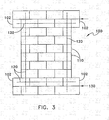
- a lightly reinforced sample CMU block wall 100 (wall 1) was constructed from standard 20.32 x 20.32 x 40.64 cm (8 X 8 X 16 in).
- the CMUs were constructed of a type N mortar, consisting of 1 part sand, 3 parts Type I Portland cement, 1 part hydrated lime, and water in sufficient quantity to make the mortar mix workable by the technician.
- the wall was ten courses high with the top two and bottom two courses 40.64 cm (16 in). wider than the central six courses forming an "I" shape. All of the blocks in the top two and bottom two courses were fully grouted to get better load transfer from a load frame (see FIG.
- a #4 steel reinforcing bar 120 was placed in the cells surrounding the central pier. All blocks containing steel reinforcing bars were fully grouted. Three-eighth inch face shell mortar bedding was used on the CMU blocks with the cross webs of units adjacent to grouted blocks fully bedded to prevent grout from flowing into adjacent cells. Dur-o-wal joint reinforcement 130 was placed in the bed joints between the top two and bottom two courses.
- the reinforcement system of the present invention in this example was comprised of an alkali-resistant glass fibrous layer comprising AR-glass manufactured by Saint Gobain Corp. of St. Catherines, Ontario, Canada, under the trademark Cem-FIL® having a sizing comprised of a blend of epoxy polymers, vinyl and amine coupling agents, and non-ionic surfactants produced by Cem FIL Reinforcements under the product label number 5197, and a coating comprised of an acrylic, and a cementitious inorganic matrix manufactured by Quickrete Companies of Atlanta, Georgia under the trademark QuickWall®.
- the QuickWall® matrix was mixed in an electric mortar mixer with water and an acrylic fortifier.
- the AR-glass fibrous layer was a coated bi-directional fibrous layer comprising a warp knit weft inserted opened meshed grid, with two rovings per inch in the weft direction and one roving per inch in the warp direction (see FIG. 2 ), and having polyester stitch yarns.
- the coating was comprised of an acrylic applied to the fibrous layer in a wt% of approximately 25-28% DPU.
- the rovings were approximately 1200 Tex.
- the AR-glass fibrous layer was cut from a 76.2 cm (30-inch) wide roll to the corresponding dimensions of the sample CMU block wall 100.
- a first layer of QuickWall® matrix was trowelled onto the sample wall at approximately 0.32 cm (1/8 inch) thick.
- a first AR-glass fibrous layer was then pressed by hand into the wet matrix.
- the first AR-glass fibrous layer was oriented so that the weft direction of the fibrous layer having two rovings was aligned horizontal to the bottom of the sample wall.
- a second layer of matrix approximately 0.32 cm (1/8 inch) in thickness was applied by trowelling.
- a second AR-glass fibrous layer was then embedded by hand into the second layer of matrix.
- the second AR-glass fibrous layer was oriented so that the weft direction of the fibrous layer was aligned perpendicular to the bottom of the sample wall.
- a third layer of matrix approximately 0.32 cm (1/8 inch) in thickness was applied by trowelling onto the second fibrous layer to form a relatively smooth surface.
- the wall sample reinforced with the reinforcement system was allowed to cure for 30 days.
- the sample wall reinforced with the exemplary reinforcement system of the present invention according to the exemplary method of the present invention was tested for in-plane shearing at the U.S. Army Engineer Research and Development Center, Construction Engineering Research Laboratory.
- the wall sample 100 with the reinforcement system 150 applied to it was set in a load test frame 160 and clamped in place using bolted steel tubing 162 over the upper and lower specimen ears 102 and steel channels and rods 164 attached to the load frame 160 using eye bolts 166.
- the load floor test frame 160 was comprised of a post-tensioned reinforced concrete reaction strong wall and a steel frame.
- a 110-kip hydraulic actuator (not shown) with a ⁇ 50.8 cm) ( ⁇ 20 in) stroke was attached to the strong wall to provide horizontal forces (HF) to the sample wall 100 through a steel tube 170 bolted to the upper concrete beam 168.
- Two 50-kip actuators (North and South) (not shown) with a ⁇ 7.62 cm ( ⁇ 3 in) stroke were attached to the steel frame and the horizontal steel tube 170 to provide axial (vertical) load (FVS and FVN) to simulate dead load above the wall specimen.
- the hydraulics for the actuator were computer controlled.
- the wall sample 100 was instrumented using two linear variable differential transducers and eight linear deflection (yo-yo) gages to monitor wall sample movements (D1 - D10) (See FIG. 5 ).
- the South actuator was set in load control and the North in stroke control; an initial 27 kip load was applied to each.
- the North actuator (applying force FVN) that was under stroke control was also slaved to the stroke signal of the South vertical actuator (applying force FVS). Loading In this manner allowed the force in the vertical actuators to vary with respect to each other while maintaining a constant 54 kip total axial load, thus forcing the top concrete beam of the test frame 160 to remain horizontal and parallel to the bottom concrete beam of the test frame 160.
- FIG. 7 shows a backbone curve of load versus displacement (at D4 and D7) for the wall 1 sample as well as the backbone curve for the control sample.
- the control sample was a CMU wall as described above without the application of the reinforcement system.
- a second wall sample 200 (wall 2) having a reinforcement system applied was tested using the same testing method as described above with respect to wall sample 1.
- Wall 2 was made in accordance with the materials and procedure described in Example 1 and the reinforcement system applied to wall 2 was made with the materials described in Example 1. The only difference between Examples 1 and 2 is with respect to the method of reinforcement application.
- the first glass fibrous layer was oriented so that the weft direction of the fabric having two rovings was at a 45° angle to the bottom of the wall running from the top left corner (US) to the bottom right corner (LN).
- the second glass fibrous layer was oriented so that the weft direction of the fibrous layer was aligned perpendicular to the bottom of the sample wall 200.
- the reinforcement of wall 2 began to show cracking at 7.6 mm (0.3 inch) horizontal displacement in the same way as wall 1. Cracks appeared at the lower reentrant corners (LS and LN) and propagated downward, as is typical with concrete shear crack growth. At 15.2 mm (0.6 inch) horizontal displacement, an X-crack began to appear across the central pier section of the wall. Then at 20.3 (0.8 inch) displacement the reinforcement developed a horizontal crack near the second pier bed joint. The back face of the CMU blocks sheared off and the wall began to buckle ending the test.
- FIG. 9 shows a backbone curve of load versus displacement (at D4 and D7) for the wall 2 sample as well as the backbone curve for the control sample.
- the control sample was a CMU wall without the application of the reinforcement system.
- a third wall sample 300 (wall 3) having a reinforcement system applied was tested using the same testing method as described above with respect to wall samples 1 and 2.
- Wall 3 was made in accordance with the materials and procedure described In Example 1.
- the reinforcement system applied to wall 3 was made with the material compositions described in Example 1, except that the final layer of matrix applied to the reinforcement was comprised of QuickWall Sanded® material from QuickCrete having more sand than the regular QuickWall® product.
- the reinforcement system applied to wall 3 included a third glass fibrous layer embedded in the third layer of matrix and a fourth layer of matrix (the QuickWall Sanded® material) applied as the top coat.
- the first glass fibrous layer was oriented so that the weft direction of the fabric having two rovings was at a 45° angle to the bottom of the wall running from the top left corner (US) to the bottom right corner (LN).
- the second glass fibrous layer was oriented so that the weft direction of the fibrous layer was at a 45° angle to the bottom of the wall running from the top right (UN) to the bottom left corner (LS).
- the third glass fibrous layer was oriented so that the weft direction of the fibrous layer was aligned perpendicular to the bottom of wall 3.
- FIG. 11 shows a backbone curve of load versus displacement (at D4 and D7) for the wall 3 sample as well as the backbone curve for the control sample.
- the control sample was a CMU wall without the application of the reinforcement system.
- three triplet samples 400 were constructed using standard 20.32 X 20.32 X 40.64 cm (8X8X16 inch) CMUs.
- the triplet samples 400 were constructed from three blocks 402, 404 and 406, placed in a stack-bond with the center block 404 offset by 1.9 cm (3 ⁇ 4 inch.)
- the reinforcement system 410 applied to the three triplet samples was made with the material compositions described in the above Examples, except that the matrix layers were comprised of QuickWall® Sanded material as opposed to the regular QuickWall® product.
- the application process of the reinforcement system for the three triplet samples 400 was identical to the application process for the three wall samples described above.
- the first triplet sample (triplet 1) received two glass fibrous layers.
- the first glass fibrous layer of the first triplet was oriented so that the weft direction of the fibrous layer having two rovings was aligned horizontal to the bottom of the triplet standing on end (as shown in FIG. 2 ).
- the second glass fibrous layer was oriented so that the weft direction of the fibrous layer was aligned perpendicular to the bottom of the triplet.
- the second triplet sample (triplet 2) also received two glass fibrous layers.
- the first glass fibrous layer of the second sample was oriented so that the weft direction of the fabric was at a 45° angle to the bottom of the triplet running from the top left corner to the bottom right corner.
- the second glass fibrous layer was oriented so that the weft direction of the fibrous layer was aligned perpendicular to the bottom of the triplet sample.
- the third triplet sample (triplet 3) received three glass fibrous layers.
- the first glass fibrous layer of the third triplet sample was oriented so that the weft direction of the fabric was at a 45° angle to the bottom of the triplet running from the top left corner to the bottom right corner.
- the second glass fibrous layer was oriented so that the weft direction of the fibrous layer was at a 45° angle to the bottom of the triplet running from the top right to the bottom left corner.
- the third glass fibrous layer was oriented so that the weft direction of the fibrous layer was aligned perpendicular to the bottom of the triplet. As with the wall samples, the triplets were allowed to cure for thirty days before testing.
- the triplets 400 were tested in a million-pound test frame. The samples were placed on the load platen of the test frame so that the center, offset block was up. Steel plates were bolted to the ends of the triplet samples and tightened to apply a 1776 kg (4800-pound) clamping force on the triplets. This force corresponds to the 150-psi axial load applied to the wall samples. The triplets were then loaded in compression at a constant load rate of 0.0686 mm/sec (0.0027 in./sec). Table 3 lists the maximum loads for each of the triplet samples. Table 3 MAXIMUM LOADS FOR TRIPLET TESTS Triplet ID Maximum Load (lb) kg 1 (43,175) 16,113 2 (47,350) 17,671 3 (48.031) 17,925
- FIG. 13 is a plot of load versus crosshead displacement for the triplet test.
- Triplet 1 had the least damage to the reinforcement system. There were a few hairline cracks approximately 2.54 cm (1 inch) long distributed along the mortar joints at about a 30 degree angle from the horizontal.
- Triplet 2 showed the most damaged to the reinforcement. Cracks developed at the reentrant corners on the triplet. A large one developed at the bottom and smaller ones developed at the top. Examination of the reinforcement revealed initiation of some delamination. After removing the triplet from the test machine, the CMU face of the center block was pulled free of the reinforcement, which remained intact.
- Triplet 3 yielded small hairline cracks at the top reentrant corners of the reinforcement, which was the only visible damage to the reinforcement side of the specimen.
- the benefit of applying the AR-glass fabric reinforced inorganic matrix to support structures such as the walls described above is to add strength to the support structure and to improve structure performance by increasing deflection limits. These benefits result in improved earthquake and explosion resistance.
- the backbone curves, as shown in FIGS. 7 , 9 , and 11 indicate the engineering strength of the support structure under consideration.
- the engineering strength is defined as the peak load transcribed by the back bone curve.
- the engineering strength is a better indicator of the system performance than the measured peak load because it incorporates a factor of safety that may or may not be present when considering the peak load value.
- FIG. 14 illustrates different configurations of fiber-reinforced-polymer (FRP) reinforcement systems applied to wall samples tested in prior tests at the U.S. Army Engineer Research and Development Center, Construction Engineering Research Laboratory under similar conditions.
- the FRP reinforced samples were loaded in in-plane shear with 54 kips axial load applied to them.
- FIG. 15 compares the engineering load increases for sample Walls 1-3 to sample walls having FRP reinforcement systems applied in the different configurations shown in FIG. 14 , over the control sample having no reinforcement.
- FRP fiber-reinforced-polymer
- Table 4 The maximum horizontal load each wall resisted, along with the engineering load and their comparisons to the control walls are listed in Table 4.
- the order of maximum horizontal load resistance for each wall is the same as the engineering load order.
- Wall 1 also exhibited the best displacement prior to failure.
- FIG. 16 compares the wall displacements with each other and also to FRP reinforced wall samples tested in prior tests.
- Table 5 lists the maximum displacement between gages D7 and D4 (See FIG. 5 ) for Walls 1-3, and compares those values to the with the control having no reinforcement applied. The walls tested showed improvements ranging from 29% for Wall 2 to 44% for Wall 1.
- Table 4 WALL LOAD COMPARISONS SHOWING MAXIMUM ENGINEERING LOAD Wall No.
- Max Displacement cm (inches) ⁇ S cm (inches) ⁇ S (%) 1 3.11 (1.224) 2.22 (0.876) 43.97 2 1.47 (0.577) 0.58 (0.229) 29.13 3 1.60 (0.631) 0.72 (0.283) 37.64 Control 0.88 (0.348)
- the AR-glass reinforced inorganic matrix reinforcing system of the present system added 209 60236 kN (47- 53 kips) of horizontal resistance, or 38% - 57% to the engineering strength of the wall samples in in-plane shear.
- the material added 1.47 to 3.1 cm (0.58 - 1.22 inches) of horizontal displacement, or 29% - 44% to the wall samples in in-plane shear.
Landscapes
- Chemical & Material Sciences (AREA)
- Engineering & Computer Science (AREA)
- Chemical Kinetics & Catalysis (AREA)
- Architecture (AREA)
- Life Sciences & Earth Sciences (AREA)
- Organic Chemistry (AREA)
- Materials Engineering (AREA)
- General Chemical & Material Sciences (AREA)
- Structural Engineering (AREA)
- General Life Sciences & Earth Sciences (AREA)
- Ceramic Engineering (AREA)
- Geochemistry & Mineralogy (AREA)
- Mechanical Engineering (AREA)
- Electrochemistry (AREA)
- Inorganic Chemistry (AREA)
- Civil Engineering (AREA)
- Laminated Bodies (AREA)
- Treatments For Attaching Organic Compounds To Fibrous Goods (AREA)
- Working Measures On Existing Buildindgs (AREA)
- Reinforced Plastic Materials (AREA)
- Woven Fabrics (AREA)
Description
- This invention relates to a method for strengthening of structural supports.
- Walls, columns and other structures constructed of materials such as concrete or cement paste, brick or masonry units, and the like are widely used as support structures. Tunnels, building structural supports, bridge supports, freeway overpass supports and parking structure supports are just a few of the many uses for these cementitious structural supports. These supports may exist in a wide variety of shapes with circular, square and rectangular cross-sections being the most common. However, numerous other cross-sectional shapes have been used, including regular polygonal shapes and irregular cross-sections. The size of structural supports also varies greatly depending upon the intended use.
- Structural supports having heights and lengths exceeding 15.24m (50 feet) are commonly used in various applications.
- It is common practice to reinforce concrete structural supports with steel rods, mesh, or bars. The steel reinforcement provides a great deal of added structural strength (e.g., compression, tensile, flexural and/or shear- resistance) to the support, but there have been numerous incidents of structural failure of these supports when subjected to asymmetric loads and horizontal displacement generated during earthquakes or explosions. Concrete structures, while adequate in compression, are subject to cracking, collapse, and partial loss due to stresses associated with earthquakes, explosions, land subsidence and overbading. Structural failure of such structures can have devastating consequences. Accordingly, there is a continuing need to enhance the ability of reinforced and unreinforced concrete and cement structural supports to withstand the asymmetric loads and horizontal displacements which are applied during an earthquake or explosion.
- One way of increasing the structural integrity of support structures is to include additional metal reinforcement prior to forming the structural support. Other design features may be incorporated into the support structure fabrication in order to increase its resistance to asymmetric loading or horizontal displacement. However, there are hundreds of thousands of existing structural supports located in earthquake prone areas, which do not have adequate metal reinforcement or structural design to withstand high degrees of asymmetric loading or horizontal displacement. Accordingly, there is a need to provide a simple, efficient and relatively inexpensive system for reinforcing such existing structural supports to prevent or reduce the likelihood of failure during an earthquake or explosion.
- One approach to reinforcing cementitious structures, such as concrete columns, is to wrap the exterior surface of the structure with a composite reinforcement layer, or fabric reinforced plastic (FRP). In
U.S. Patent No. 5,607,527 to Isley, Jr. , a composite reinforcement layer having at least one fabric layer located within a resin matrix is wrapped around the exterior surface of a concrete column. The fabric layer has first and second parallel selvedges that extend around the circumferential outer surface of the column in a direction substantially perpendicular to the column axis. Preferred fibers disclosed by Isley include ones made from glass, polyaramid, graphite, silica, quartz, carbon, ceramic and polyethylene. Suitable resins suggested by this patent include polyester, epoxy, polyamide, bismaleimide, vinylester, urethanes, and polyurea, with epoxy-based resins being preferred. - Another approach to reinforcing a cementitious structural support is disclosed in
U.S. Patent No. 6,017,588 to Watanabe, et al. This patent discloses using an FRP to reinforce a structural support by forming a primer layer on the surface of the support structure, forming, if necessary, a putty layer on the primer layer, applying an impregnating resin on the primer layer (or putty layer) before, after or, before and after, cladding with fiber sheets to allow the resin to penetrate into the spaces in the fiber sheets, followed by curing the resin, the primer, putty and impregnating resin. The primer, putty and impregnating resin of this reference all include a resin composition. The disclosed fiber sheets may include carbon, aramid or glass fibers. The asserted advantage of the reinforcement structure of this patent is increased adherence of the reinforcement to the surface of the structural support. - Reinforcing FRP systems such as those described above can often be flammable, toxic and difficult to handle during application. They also provide, after curing, poor fire resistance, poor bonding to the concrete or brick being reinforced, and poor water/air permeability, resulting in the creation of moisture accumulation. Additionally, they are fairly expensive and tend to delaminate upon failure.
- A repair or reinforcement system for existing support structures or for new construction support structures is needed.
-
EP 1 063 366 (Weber Broutinclaim 1. - In accordance with of the present invention, a method for reinforcing a structural support is provided having characterizing features of
claim 1. - Unlike other types of glass fibers, such as E-glass, AR-glass has a high degree of resistance to alkali attack and higher strength retention over time. This is due to the presence of an optimum level of Zirconia (ZrO2) in the glass fibers. This type of glass exhibits a high degree of chemical resistance, resisting the very high alkalinity produced by the hydration of conventional cementitious materials such as ordinary Portland cement.
- The preferred cementious material matrix is comprised of material such as cement, concrete or mortar. More preferably the cementious material matrix comprises ordinary Portland cement having chopped reinforcing fibers dispersed throughout the cement. Such fibers may include those made from carbon, AR-glass, cellulose, rayon or polymeric materials, such as aramids, polyolefins, polyester, or hybrids thereof, for example.
-
-
FIG. 1 is a perspective cross-sectional view of a support structure having an exemplary reinforcement system according to the present invention. -
FIG. 2 is a partial cross-sectional view of a support structure having one embodiment of the reinforcement system of the present invention. -
FIG. 3 is a front view of a concrete masonry unit (CMU) wall sample used in testing alternative embodiments of the reinforcement system of the present invention. -
FIG. 4 is a front view of a wall sample mounted in a test frame. -
FIG. 5 is a diagram of a wall sample and test frame showing locations of displacement measurements and directions of horizontal and vertical forces. -
FIG. 6 is a front view ofwall sample 1 showing crack growth during in-plane shear testing. -
FIG. 7 is a graph showing a backbone curve of load versus displacement for thewall sample 1 and the backbone curve for the control sample. -
FIG. 8 is a front view ofwall sample 2 showing crack growth during in-plane shear testing. -
FIG. 9 is a graph showing a backbone curve of load versus displacement for thewall sample 2 and the backbone curve for the control sample. -
FIG. 10 is a front view ofwall sample 3 showing crack growth during in-plane shear testing. -
FIG. 11 is a graph showing a backbone curve of load versus displacement for thewall sample 3 and the backbone curve for the control sample. -
FIG. 12 is a perspective view of a triplet sample having an exemplary reinforcement system according to the present invention. -
FIG. 13 is a graph showing a plot of load versus crosshead displacement for the triplet tests. -
FIG. 14 illustrates different configurations of fiber-reinforced-polymer (FRP) reinforcement systems applied to wall samples tested under conditions similar to those employed in testing Walls 1-3. -
FIG. 15 is a graph comparing the engineering load increases for wall samples 1-3 to wall samples having FRP reinforcement systems applied in the different configurations shown inFIG. 14 , versus the control sample having no reinforcement. -
FIG. 16 is a graph comparing the wall displacements for wall samples 1-3 with each other and also to previously tested FRP reinforced wall samples. - A reinforcement system and a method of reinforcing a structural support using the reinforcement system of the present invention are provided. The reinforcement system has improved bonding with a cementitious support structure and is less likely to delaminate from the structural support than existing reinforcement systems.
- In accordance with the present invention, the following terms are defined:
- Adhesive bonded crossed laid fibers/mesh. Woven fabrics consisting of layers of parallel textile yarns superimposed on each other at acute or right angles. These layers are bonded at the intersections of the yarns by an adhesive, glue or by thermal bonding.
- Cementitious material/composite. An inorganic hydraulically setting material, such as those containing portland cement, mortar, plaster, fly ash, slag, silica fume, metakaolin, gypsum, geopolymer and/or other ingredients, such as aggregate, including sand or gravel, additives or admixtures, such as foaming agents, resins, including acrylic fortifiers, moisture resistant additives, shrinkage reducing admixtures (SRA), air-entraining (AE) admixtures, fire retardants, and chopped fibers, including glass, PVA, polypropylene, cellulose, graphite, or hybrids thereof.
- Coatings/binders/finishes. Compounds, generally organic, applied to fabrics after processing (e.g., weaving or knitting) to protect the fibers and give the fabric stability.
- Fiber. A general term used to refer to filamentary materials. Often, fiber is used synonymously with filament. It is generally accepted that a filament routinely has a finite length that is at least 100 times its diameter. In most cases, it is prepared by drawing from a molten bath, spinning, or by deposition on a substrate.
- Filament. The smallest unit of a fibrous material. The basic units formed during drawing and spinning, which are gathered into strands of fiber for use in composites. Filaments usually are of extreme length and very small diameter. Some textile filaments can function as a yarn when they are of sufficient strength and flexibility.
- Glass fiber. A fiber spun from an inorganic product of fusion that has cooled to a rigid condition without crystallizing.
- Glass Filament. A form of glass that has been drawn to a small diameter and long lengths.
- Inorganic Matrix. A matrix material comprising mostly inorganic ingredients, such as ceramics, glasses, cementitious materials, and geopolymers (inorganic resins), for example.
- Knitted fabrics. Fabrics produced by interlooping chains of filaments, roving or yarn.
- Mat. A fibrous material consisting of randomly oriented chopped filaments, short fibers, or swirled filaments loosely held together with a binder.
- Roving. A number of continuous filaments, strands, or collected into a parallel bundle.
- Sizing. Compounds, generally organic, applied as a fine coating to rovings after drawing of glass filaments in order to bind the individual filaments together and stiffen them to provide abrasion resistance during processing (e.g., weaving or knitting).
- Tensile strength. The maximum load or force per unit cross-sectional area, within the gage length, of the specimen. The pulling stress required to break a given specimen.
- Tex. A unit for expressing linear density (or gauge) equal to the weight in grams of 1 kilometer of yarn, filament, fiber or other textile strand.
- Warp. The yarn, fiber or roving running lengthwise in a woven fabric. A group of yarns, fibers or roving in long lengths and approximately parallel.
- Warp knit. Warp knitting is a type of knitting in which the yarns generally run lengthwise in the fabric.
- Weave. The particular manner in which a fabric is formed by interlacing yarns, fibers or roving. Weave can be further defined by "type of weave", such as leno weave, for example.
- Weft. The transverse threads or fibers in a woven fabric. Those fibers running perpendicular to the warp. Also called fill, filling yarn or woof.
- Woven fabric. A material (usually a planar structure) constructed by interlacing yarns, fibers, roving or filaments, to form such fabric patterns as plain, harness satin, or leno weaves.
- Yarn. An assemblage of filaments, fibers, or strands, either natural or manufactured, to form a continuous length that is suitable for use in knitting, weaving or interweaving into textile materials. The assemblage of filaments, fibers or strands may have some or no twist.
- Referring to
FIG. 1 , areinforcement system 10 is shown reinforcing asupport structure 20. The present invention may be used to reinforce a wide variety of support structures. Such support structures may include, for example, walls, beams, exterior insulation fabric systems ("EIFS") slabs, chimneys, stacks, tanks, columns, silos, shafts, pipes, conduits, tunnels and the like. The support structure may be planar, circular, or any other shape. The invention is especially well suited for reinforcing support structures comprised of cementitious or masonry materials such as cement, concrete, brick, and cinder block, which may be reinforced or unreinforced. One structural support especially suited for the reinforcement system of the present invention is unreinforced masonry (URM) walls. - The
reinforcement system 10 comprises at least one alkali-resistant open fibrous layer 12 (two fibrous layers are shown inFIG. 1 ) and aninorganic matrix 14. The fibrous layers 12 are embedded within thematrix 14. Thesystem 10 is applied to a surface of thesupport structure 20. - The following detailed description and examples describe use of the present invention to support a structure through application to one surface of the structure; however, it will be understood by those skilled in the art that the present invention is not limited thereto, but may be applied to any number of surfaces depending on the shape or type of support structure. Thus, for example, the reinforcement system of the present invention may be applied to an outside surface and an inside surface of a wall of a building, pipe, wall or other structure.
- The
inorganic matrix 14 preferably comprises a cementitious material, such as cement paste, mortar or concrete, and/or other types of materials such as gypsum and geopolymers (inorganic resins). More preferably the inorganic matrix comprises Portland cement having chopped fibers dispersed throughout the cement. Preferably the fibers are AR-glass fibers but may also include, for example, other types of glass fibers, aramids, polyolefins, carbon, graphite, polyester, PVA, polypropylene, natural fibers, cellulosic fibers, rayon, and hybrids thereof. The inorganic matrix may include other ingredients or additives such as fly ash, latex, slag and metakaolin, resins, such as acrylics, polyvinyl acetate, or the like, ceramics, including silicon oxide, titanium oxide, and silicon nitrite, setting accelerators, water and/or fire resistant additives, such as silioxane, borax, fillers, setting retardants, dispersing agents, dyes and colorants, light stabilizers and heat stabilizers, shrinkage reducing admixtures, air entraining agents, or combinations thereof, for example. In a preferred embodiment, the inorganic matrix includes a resin that may form an adhesive bond with a resinous coating applied to the alkali-resistant open fibrous layer. - Preferably the inorganic matrix has good bonding with the support structure. Portland cement, for example, has excellent bonding to concrete, bricks and concrete masonry units (CMUs). The inorganic matrix may contain curing agents or other additives such as coloring agents, light stabilizers and heat stabilizers, for example.
- One
inner surface 16 of the inorganic matrix is preferably in direct contact with asurface 22 of the support structure. Due to the preferred compatibility of theinorganic matrix 14 with thesupport structure 20, there is no requirement that any adhesive material be applied between the two materials, however the addition of an adhesive between, or among, the inorganic matrix and the support structure is not precluded. - The alkali-resistant
fibrous layers 12 are a reinforcement material for theinorganic matrix 14. The fibrous layers 12 preferably provide long term durability to thereinforcement system 10 in the highly alkaline environment of the inorganic matrix where the matrix is comprised of materials such as cement paste, mortar, or concrete or geopolymers. The fibrous layers may be comprised of glass fibers, PVA fibers, carbon fibers or aramid fibers, for example, or any combination thereof. Most preferably, the fibrous layers are comprised of AR-glass (alkali-resistant glass), such as that manufactured by Saint Gobain Vetrotex under the trademark Cem-FIL®. Unlike other types of glass fibers, such as E-glass, AR-glass has a high degree of resistance to alkali attack and a higher strength retention over time.. This is due to the presence of an optimum level of Zirconia (ZrO2), e.g. preferably about 10% to about 25% ZrO2, in the glass fibers. This type of glass exhibits a high degree of chemical resistance, resisting the very high alkalinity produced by the hydration of cementitious materials such as ordinary Portland cement. In addition, AR-glass has superior strengthening properties necessary for use in earthquake and explosion-resistant applications. It has high tensile strength and modulus and does not rust. Although less preferred, other glass fibers may be employed, such as E-glass, ECR-glass, C-glass, S-glass and A-glass, which are not inherently alkali-resistant, when such fibers are coated with an alkali-resistant material, such as polyvinyl chloride resinous coating. - The preferred AR-glass fibers are preferably produced as rovings or yarns. The linear density of the AR-glass fibers preferably ranges from about 76 Tex where yarns are employed to 2,500 tex where rovings are employed. Where carbon fibers are used, they are preferably provided as tows, with the filament count preferably ranging from about 3,000 to 24,000. Preferred properties of the AR-glass include a virgin filament tensile strength of at least about 1275.53 MPa (185,000 psi) or higher, Young's modulus of elasticity of about 68947 to 82737 MPa (10-12 million psi), train at breaking point of at least about 1.5% or higher, water uptake at less than about 0.1%, and softening temperature of about 860°C.
- The fibrous layers 12 may be formed, for example, by various methods of weaving, such as plain or leno weave, or by knitting or laying of continuous fibers. The fibrous layers may also be laid scrim or be formed from discontinuous or continuous fibers randomly oriented In a non-woven mat. Referring to
FIG. 2 , in one preferred embodiment, thefibrous layers openings 18 in the fibrous layer 12 (seeFIG. 1 ) should be sufficient to allow interfacing between thelayers 14a-c of theinorganic matrix 14 disposed on each side of thefibrous layers - The fibrous layer also preferably includes a sizing. Preferred sizings for use with a fibrous layer comprised of AR-glass include aqueous sizings comprising one of the following blends: 1) an epoxy polymer, vinyl and amine coupling agents and a non-ionic surfactant; 2) an epoxy polymer, amine coupling agent and a non-ionic surfactant; 3) an epoxy polymer, metacrylic and epoxy coupling agents, and cationic and non-ionic surfactants (paraffin lubricants); 4) anhydrous polymerized acrylate amine (for example, the substance disclosed in
PCT Patent Application No. WO 99/31025 U.S. Patent No. 5,961,684 to Moireau et al. , which is incorporated herein by reference), vinyl and amine coupling agents, and a non-ionic surfactant, each of the above blends being produced by Cem FIL Reinforcements of Saint Gobain Vetrotex Cem-FIL® S.L., a Saint Gobain Vertrotex company. Preferably, the non-ionic surfactant comprises an organo-silane. These sizings are compatible with the preferred coatings for the AR-glass fibrous layer as described below and the cementitious matrices, and improve initial glass strength and ease of fabric forming. The sizings preferably comprise not more than 2.5 % by weight, and most preferably less than 1.5% by weight of the fibrous layer. - The fibrous layers may also include an
optional coating 24. Coatings are preferred where the fibrous layer is comprised of glass; however, coatings are not necessary where the fibrous layer is comprised of AR-glass, PVA, carbon or aramid fibers. Thecoating 24 provides mechanical and chemical protection to the glass fibrous layers 12. The coating is preferably an acrylate and/or vinyl chloride containing a polymer or polymers.Coating 24 is preferably acrylic or PVC plastisol, but may be poly vinyl alcohol (PVA), styrene-butadiene rubber (SBR), polyolefin, acrylic acid, unsaturated polyesters, vinyl ester, epoxies, polyacrylates, polyurethanes, polyolefins, phenolics, and the like. Examples of preferred coatings include an acrylic coating manufactured by Saint-Gobain Technical Fabrics, a Saint-Gobain company, under the label number 534 and a PVC plastisol coating manufactured by Saint-Gobain Technical Fabrics under the label number V38. The use of PVC plastisol as a coating further improves the alkali resistance of the fibrous layer in the inorganic matrix. The use of acrylic as a coating promotes adherence of the fibrous layer to inorganic matrix, especially where the matrix includes acrylic. - The coating can further contain a water resistant additives, such as, paraffin, and combination of paraffin and ammonium salt, fluoro chemicals designed to impart alcohol and water repellency, such as FC-824 from 3M Co., organohydrogenpolysiloxanes, silicone oil, wax-asphalt emulsions and poly(vinyl alcohol) with or without a minor amount of poly(vinyl acetate). In addition, the flame retardants, such as bromated phosphorous complex, halogenated paraffin, colloidal antimony pentoxide, borax, unexpanded vermiculate, clay, colloidal silica and colloidal aluminum can be added to the coating. Further, optional ingredients, such as pigments, preservatives, dispersants, catalysts, fillers and the like may be added to the coating.
- The coating is preferably applied by dip-coating the fibrous layer into the coating, but may applied by any other technique known in the art, such as spraying, roll coating, and the like. The wt% of the coating will depend on the type of coating, preferably ranging from 10 to 200 wt% of the total weight of the coating and fiber. The coating can be applied in various thicknesses. Preferably the coating is applied so that no fibers of the fibrous layer protrude from the coating, however, the coating may alternatively be intermittently applied. After application of the
coating 24, theopenings 18 in thefibrous layers layers 14a-c of theinorganic matrix 14 disposed on each side of the fibrous layers. - According to a preferred embodiment of the present invention, the sizing and coating of an AR-glass fibrous layer are combined to optimize tensile performance and retention of tensile strength after aging, and to improve compatibility between the AR-glass, sizing, coating and cementitious matrix. Preferably the
coating 24 is adherent to the sizing and theinorganic matrix 14 is adherent to thecoating 24. A preferred combination includes a sizing selected from the group consisting of 1) an epoxy polymer, vinyl and amine coupling agents and a non-ionic surfactant; 2) an epoxy polymer, amine coupling agent and a non-ionic surfactant; 3) an epoxy polymer, metacrylic and epoxy coupling agents, and cationic and non-ionic surfactants (paraffin lubricants); 4) anhydrous polymerized acrylate amine, metacrylic and epoxy coupling agents and a non-ionic surfactant; and 5) anhydrous polymerized epoxy amine, vinyl and amine coupling agents, and a non-ionic surfactant, and a polymeric coating selected from the group consisting of acrylic and PVC plastisol. Table 1 shows the results of tensile strength and tensile retention testing following a 5% NaOH accelerated aging test, a Tri-alkali test (TAT) and a strand in cement (SIC) test using various coating/sizing combinations, as compared with uncoated AR-glass and E-glass. -
Table 1 Tensile Strength (g/tex) Tensile Retention (%) Material type Unaged Aged TAT Aged NaOH Aged SIC Retention TAT Retention NaOH Retention SIC Sizing Coating Initial TAT NaOH SIC TAT NaOH SIC Label Type Label Type Cem-FIL 5197 greige 51971 aqueous resin none none 40.65 Cem-FIL 5197 V38 5197 aqueous resin V382 PVC plastisol 60.14 61.24 57.05 101.83 94.86 Cem-FIL 5197 534 5197 aqueous resin 5343 acrylic 62.40 39.89 37.97 63.93 60.85 Cem-FIL 019/2 V38 019/24 aqueous resin V38 PVC plastisol 71.97 74.15 64.90 103.03 90.18 Cem-FIL 019/3A15 019/35 aqueous resin A156 PVA 57.75 39.58 68.54 Cem-FIL 020/2 K29 020/27 anhydrous resin K298 acrylic 88.2 89.93 45.04 31.5 101.96 51.07 35.71 Cem-FIL 020/2 P3 020/2 anhydrous resin P39 EEA/SA 86.69 88.85 53.1 32.7 102.49 61.25 37.72 Cem-FIL 020/2 V38 Q20/2 anhydrous resin V38 PVC plastisol 84.28 89.17 63.47 54.2 105.80 75.31 64.31 Cem-FIL 5197 K29 5197 aqueous resin K29 acrylic 64.64 83.85 0 26 129.72 0.00 40.22 Cem-FIL 5197 P3 5197 aqueous resin P3 EEA/SA 66.06 73.09 0 26.4 110.64 0.00 39.96 Cem-FIL 020/1 A15 020/110 anhydrous resin A15 PVA 73.93 47.61 64.40 E-glass K29 aqueous resin K29 acrylic 83.97 56 33.16 14.1 66.69 39.49 16.79 E-glass P3 aqueous resin P3 EEA/SA 89.09 68.04 0 14.4 76.37 0.00 16.16 1 A blend of an epoxy polymer, vinyl and amine coupling agents and a non-ionic surfactant produced by Cem FIL Reinforcements.
2Produced by Cem FIL Reinforcements.
3Produced by Cem FIL Reinforcements.
4A blend of an epoxy polymer, vinyl and amine coupling agents and a non-ionic surfactant produced by Cem FIL Reinforcements.
5A blend of an epoxy polymer, metacrylic and epoxy coupling agents and non-ionic and cationic surfactants produced by Cem FIL Reinforcements.
6Produced by Cem FIL Reinforcements.
7 A blend of anhydrous polymerized epoxy amine, vinyl and amine coupling agents and a non-ionic surfactant produced by Cem FIL Reinforcements.
8 Produced by Cem FIL Reinforcements.
9 Produced by Cem FIL Reinforcements.
10 A blend of anhydrous polymerized acrylate amine, metacrylic and epoxy coupling agents and a non-ionic surfactant produced by Cem FIL Reinforcements. - In performing the 5% NaOH accelerated aging test, glass fiber specimens were collected from good quality, undamaged fabric. Specimens from both the machine and cross-machine direction were tested, each specimen having a length of 330mm and a width of 50 mm. The specimens were freely submerged in an alkali bath of 5% NaOH (sodium hydroxide) in distilled water for 28 days, with the bath being replaced after each test. Following conditioning in the alkali bath, the specimens were washed with at least 1 liter of distilled water at least ten times. Following the washing, the fabric specimens were dried for seven days at room temperature. Following drying, the fabric specimens were tested in tension at a rate of 305 cm/hr (2 in/min) using a 12.7 cm (5 in) jaw span.
- The TAT test was performed in accordance with the draft European Standard (Copyright 1997, CEN Members) prepared by the Technical Committee for the European Committee for Standardization (CEN) and submitted to CEN members. Coated single end samples were placed in a tri-alkali solution consisting of 1g of NaOH, 0.5g of Ca(OH)2, and 4g of KOH in 1 liter of distilled water at 60°C. After twenty-four hours, they were taken out and rinsed in tap water until a pH of 9 was reached. The samples were then placed in an acid solution of 0.5% HCL for one hour, taken out and rinsed in tap water until a pH of 7 was reached. The samples were then dried for one hour in a 60°C oven. Following drying in the oven, the samples were allowed to dry at room temperature for twenty-four hours and then tested in tension.
- SIC tests evaluate the alkali-resistance of glass strand or filaments in cement, by measuring the tensile strength of a strand set in a block of cement mortar. Well-stretched strands are installed in a metallic mold frame with the free ends coated with a coating mixture to protect the parts of the fibers that will not be in contact with the cement. After mixing the cement paste, having a water-to-cement ratio of 1:0.43 and a cement-to-sand ratio of 1:0.34, the mold is filled with the cement paste and vibrated to avoid formation of air bubbles near the strands. The cement is allowed to set for one hour at room temperature, then for twenty-three hours in cold water, after which the mold frame is removed.
- The samples containing the cement block and strands are subsequently aged by soaking in water at 80°C for four days. The samples are then immersed in cold water. The samples are then tested for tensile strength using a dynamometer.
- The results of the TAT, NaOH accelerated aging, and SIC tests reveal that certain coated AR-glass fibers have improved tensile performance over uncoated AR-glass and E-glass. The test results also indicate that the combination of sizing and coating affects the tensile performance. Anhydrous sizings outperform aqueous sizings. Further, the results reveal that a sizing/coating combination of Cem-FIL anhydrous sizing 020 with the Cem-FIL PVC plastisol V38 coating provides the best tensile performance.
- The
reinforcement system 10 can be applied to an existingstructural support 20 in the following exemplary manner. Anoutside surface 22 of thestructural support 20 is wetted, preferably with water. (Prior to wetting the outside surface of the structural support, It is preferred that the surface be cleared of extraneous matter and cleaned with a mild soap, if necessary.) Afirst layer 14c of inorganic matrix is then applied by trowelling or similar coating technique to the wettedsurface 22 of thestructural support 20. It should be understood that the matrix is in a wet or uncured state when it is applied to thesupport 20. Preferably, the thickness of the matrix layers ranges from 0.16 to 0.63 cm (1/16 to ¼ inch), and more preferably the thickness is approximately 0.32 cm (1/8 inch). If the thickness is too large, the matrix may exhibit shrinkage cracking. - Once the
first layer 14c of inorganic matrix has been applied, an alkali-resistant fibrous layer 12b is embedded into thefirst layer 14c of the matrix. This may be performed by hand or by any automated method. Generally, the fibrous layers will be provided in roll form and will be cut from the roll to the desired shape and length. The fibrous layers may be oriented in a variety of ways both with respect to the orientation of the support structure and with respect to the orientation of the other fibrous layers employed in the reinforcement system. Varying the orientation of the fibrous layers in these ways can improve the strengthening and ductility characteristics of the reinforcement system. - After embedding a
fibrous layer 12b into thefirst layer 14c of matrix, a second layer 14b of inorganic matrix is applied over thefibrous layer 12b. Again, this layer preferably has a thickness between 0.16 to 0.63 cm (1/16 and % inch), and more preferably is approximately 0.32 cm (1/8 inch). After eachlayer 14a-c of inorganic matrix is applied, the matrix may be trowelled to provide a substantially smooth surface. - As shown in the exemplary embodiment in
FIGS. 1 and 2 , after the second layer 14b of inorganic matrix has been applied, a secondfibrous layer 12a may be embedded in the second layer 14b of matrix and athird layer 14a of inorganic matrix applied on top of the secondfibrous layer 12a. If desired, a third fibrous layer may be embedded in thethird matrix layer 14a and a fourth layer of inorganic matrix applied on top of the third fibrous layer. Although it is preferred that the reinforcement system include between 1 and 3 fibrous layers and between two and four inorganic matrix layers, additional fibrous layers and inorganic layers may be employed. The additional fibrous layers and layers of inorganic matrix will be applied in the same manner as described above. Once all the desired layers of the system have been applied, the system may be allowed to dry or cure on its own or may be cured or set by any known means. - It is preferred that the
reinforcement system 10 be applied to thesurface 22 of thesupport structure 20 so that substantially the entire surface is covered. However, in certain applications, it may be beneficial to apply the reinforcement system only to those portions of the support structure which are most likely to fail, or experience the highest load in shear or bending, for example. - The reinforcement system increases the overall performance of the structural supports by increasing the load to failure and by increasing the deflection limits or ductility of the structural support system. Unlike the conventional fiber-reinforced polymer systems which may be toxic, difficult to handle, costly, subject to delamination, and have poor fire resistance and water/air permeability, the reinforcement system of the present invention is easy to install, and has improved fire resistance and improved bonding to concrete, concrete masonry units (CMU) and brick. Additionally the reinforcement system is less likely to delaminate from the structural support, allows the concrete or CMUs to breathe due to similar air and water permeability, has a pleasant aesthetic appearance (can be blended into the concrete finish) and is lower In cost.
- This invention and its advantages are further described with reference to the following specific examples. The examples are merely intended to be illustrative and not to be construed as limiting the scope of the invention. In the following examples the method as described above was employed and tested on masonry wall and triplet samples. Results were obtained which indicate significantly improved seismic strengthening for the overall support system.
- Referring to
FIG. 3 , a lightly reinforced sample CMU block wall 100 (wall 1) was constructed from standard 20.32 x 20.32 x 40.64 cm (8 X 8X 16 in).CMUs 110. The CMUs were constructed of a type N mortar, consisting of 1 part sand, 3 parts Type I Portland cement, 1 part hydrated lime, and water in sufficient quantity to make the mortar mix workable by the technician. The wall was ten courses high with the top two and bottom two courses 40.64 cm (16 in). wider than the central six courses forming an "I" shape. All of the blocks in the top two and bottom two courses were fully grouted to get better load transfer from a load frame (seeFIG. 4 ) during testing and increase the probability of wall failure not occurring within the wide top and bottom sections of the wall. A #4steel reinforcing bar 120 was placed in the cells surrounding the central pier. All blocks containing steel reinforcing bars were fully grouted. Three-eighth inch face shell mortar bedding was used on the CMU blocks with the cross webs of units adjacent to grouted blocks fully bedded to prevent grout from flowing into adjacent cells. Dur-o-waljoint reinforcement 130 was placed in the bed joints between the top two and bottom two courses. - The reinforcement system of the present invention in this example was comprised of an alkali-resistant glass fibrous layer comprising AR-glass manufactured by Saint Gobain Corp. of St. Catherines, Ontario, Canada, under the trademark Cem-FIL® having a sizing comprised of a blend of epoxy polymers, vinyl and amine coupling agents, and non-ionic surfactants produced by Cem FIL Reinforcements under the product label number 5197, and a coating comprised of an acrylic, and a cementitious inorganic matrix manufactured by Quickrete Companies of Atlanta, Georgia under the trademark QuickWall®. The QuickWall® matrix was mixed in an electric mortar mixer with water and an acrylic fortifier.
- The AR-glass fibrous layer was a coated bi-directional fibrous layer comprising a warp knit weft inserted opened meshed grid, with two rovings per inch in the weft direction and one roving per inch in the warp direction (see
FIG. 2 ), and having polyester stitch yarns. The coating was comprised of an acrylic applied to the fibrous layer in a wt% of approximately 25-28% DPU. The rovings were approximately 1200 Tex. The AR-glass fibrous layer was cut from a 76.2 cm (30-inch) wide roll to the corresponding dimensions of the sampleCMU block wall 100. - A first layer of QuickWall® matrix was trowelled onto the sample wall at approximately 0.32 cm (1/8 inch) thick. A first AR-glass fibrous layer was then pressed by hand into the wet matrix. The first AR-glass fibrous layer was oriented so that the weft direction of the fibrous layer having two rovings was aligned horizontal to the bottom of the sample wall. Next a second layer of matrix approximately 0.32 cm (1/8 inch) in thickness was applied by trowelling. A second AR-glass fibrous layer was then embedded by hand into the second layer of matrix. The second AR-glass fibrous layer was oriented so that the weft direction of the fibrous layer was aligned perpendicular to the bottom of the sample wall. Finally, a third layer of matrix approximately 0.32 cm (1/8 inch) in thickness was applied by trowelling onto the second fibrous layer to form a relatively smooth surface.
- Before conducting the testing described below, the wall sample reinforced with the reinforcement system was allowed to cure for 30 days.
- The sample wall reinforced with the exemplary reinforcement system of the present invention according to the exemplary method of the present invention was tested for in-plane shearing at the U.S. Army Engineer Research and Development Center, Construction Engineering Research Laboratory. Referring to
FIGS. 3 - 5 , thewall sample 100 with thereinforcement system 150 applied to it was set in aload test frame 160 and clamped in place using boltedsteel tubing 162 over the upper andlower specimen ears 102 and steel channels androds 164 attached to theload frame 160 usingeye bolts 166. The loadfloor test frame 160 was comprised of a post-tensioned reinforced concrete reaction strong wall and a steel frame. A 110-kip hydraulic actuator (not shown) with a ±50.8 cm) (± 20 in) stroke was attached to the strong wall to provide horizontal forces (HF) to thesample wall 100 through asteel tube 170 bolted to the upperconcrete beam 168. Two 50-kip actuators (North and South) (not shown) with a ± 7.62 cm (± 3 in) stroke were attached to the steel frame and thehorizontal steel tube 170 to provide axial (vertical) load (FVS and FVN) to simulate dead load above the wall specimen. The hydraulics for the actuator were computer controlled. - The
wall sample 100 was instrumented using two linear variable differential transducers and eight linear deflection (yo-yo) gages to monitor wall sample movements (D1 - D10) (SeeFIG. 5 ). For the in-plane shear testing, the South actuator was set in load control and the North in stroke control; an initial 27 kip load was applied to each. The North actuator (applying force FVN) that was under stroke control was also slaved to the stroke signal of the South vertical actuator (applying force FVS). Loading In this manner allowed the force in the vertical actuators to vary with respect to each other while maintaining a constant 54 kip total axial load, thus forcing the top concrete beam of thetest frame 160 to remain horizontal and parallel to the bottom concrete beam of thetest frame 160. This configuration put an in-plane shear load in the wall sample. Cyclic horizontal forces (HF) were applied to the wall sample using the horizontal actuator. Table 2 shows the input time (sec) and displacement mm (in.) that the wall was subjected to during the test. Displacement forces were terminated upon wall sample failure.Table 2 Time (Sec) Displacement mm (in.) Time (Sec.) Displacement mm (in.) Time (Sec) Displacement mm (in.) 0 0 (0) 400 0 (0) 787.5 -10.2 (-0.4) 12.5 0.5 (0.02) 412.5 2.51 (0.1) 800 0 (0) 25 0 (0) 425 0 (0) 812.5 15.2 (0.6 37.5 0.5 (-0.02) 437.5 -2.5 (0.1) 825 0 (0) 50 0 (0) 450 0 (0) 837.5 -15.2 (-0.6) 62.5 0.5 (0.02) 462.5 2.51 (0.1) 850 0 (0) 75 0 (0) 475 0 (0) 862.5 15.2 (0.6) 87.5 -0.5 (-0.02) 487.5 -2.5 (-01) 875 0 (0) 100 0 500 0 (0) 887.5 -15.2 (-06) 112.5 1 (0.04) 512.5 5 (0.2) 900 0 (0) 125 0 (0) 525 0 (0) 912.5 20.3 (0-8) 137.5 -1 (-0.04) 537.5 -5.1 (-0.2) 925 0 (0) 150 0 (0) 550 0 (0) 937.5 -20.3 (-0.8) 162.5 1 (0.04) 562.5 5 (0.2) 950 0 (0) 175 0 (0) 575 0 (0) 962.5 20.3 (0.8) 187.5 -1 (-0.04) 587.5 -5.1 (0) 975 0 (0) 200 0 (0) 600 0 (0) 987.5 -20.3 (-0.8) 212.5 1,5 (0.06) 612.5 7.6 (0.3) 1000 0 (0) 225 0 (0) 625 0 (0) 1012.5 25.4 (1) 237.5 -1.5 (-0.06) 637.5 7.6 (-0.3) 1025 0 (0) 250 0 (0) 650 0 (0) 1037.5 -25.4 (-1) 262.5 1.5 (0.06) 662.5 7.6 (0.3) 1050 0 (0) 275 0 (0) 675 0 (0) 1062.5 25.4 (1) 287.5 -1.5 (-0.06) 687.5 -7.6 (-0.3) 1075 0 (0) 300 0 (0) 700 0 (0) 1087.5 -25.4 (-1) 312.5 2 (0.08) 712.5 10.2 (0.4) 1100 0 (0) 325 0 (0) 725 0 (0) 1112.5 30.5 (1.2) 337.5 -2 (-0.08) 737.5 -10.2 (-0.4) 1125 0 (0) 350 0 (0) 750 0 (0) 1137.5 -30.5 (-1.2) 362.5 2 (0.08) 762.5 10.2 (0.4) 1150 0 (0) 375 0 (0) 775 0 (0) 1162.5 30.5 (1.2) 387.5 -2 (-0.08) - Referring to
FIG. 6 , during the course of the wall test forwall 1, cracking of the reinforcement began during the 5.1 mm (0.2 inch) horizontal displacement cycles at the lower corners (LS and LN) of the sample and then began to propagate downward as a typical concrete shear crack at around 45 degrees. At 15.2 and 20.3 mm (0.6 and 0.8 inch) horizontal displacements, cracking began to appear intermittently in the middle of the central pier starting the formation of an X-crack. At 25.4 mm (1.0 inch) displacement, significantly more cracks appeared diagonally from the upper north reentrant corner (UN) downward. At the same time cracking began growing upward and at a 45-degree angle from that corner. Finally, at 30.5 mm (1.2 inch) displacement, the reinforcement cracked from the upper north reentrant corner (UN) diagonally across the entire sample to the south reentrant corner (LS), and the back face of the pier CMU blocks sheared off and fell to the floor ending the test. -
FIG. 7 shows a backbone curve of load versus displacement (at D4 and D7) for thewall 1 sample as well as the backbone curve for the control sample. The control sample was a CMU wall as described above without the application of the reinforcement system. - A second wall sample 200 (wall 2) having a reinforcement system applied was tested using the same testing method as described above with respect to
wall sample 1.Wall 2 was made in accordance with the materials and procedure described in Example 1 and the reinforcement system applied towall 2 was made with the materials described in Example 1. The only difference between Examples 1 and 2 is with respect to the method of reinforcement application. In applying the reinforcement system ofwall 2, the first glass fibrous layer was oriented so that the weft direction of the fabric having two rovings was at a 45° angle to the bottom of the wall running from the top left corner (US) to the bottom right corner (LN). The second glass fibrous layer was oriented so that the weft direction of the fibrous layer was aligned perpendicular to the bottom of thesample wall 200. - Referring to
FIG. 8 , the reinforcement ofwall 2 began to show cracking at 7.6 mm (0.3 inch) horizontal displacement in the same way aswall 1. Cracks appeared at the lower reentrant corners (LS and LN) and propagated downward, as is typical with concrete shear crack growth. At 15.2 mm (0.6 inch) horizontal displacement, an X-crack began to appear across the central pier section of the wall. Then at 20.3 (0.8 inch) displacement the reinforcement developed a horizontal crack near the second pier bed joint. The back face of the CMU blocks sheared off and the wall began to buckle ending the test. -
FIG. 9 shows a backbone curve of load versus displacement (at D4 and D7) for thewall 2 sample as well as the backbone curve for the control sample. Again, the control sample was a CMU wall without the application of the reinforcement system. - A third wall sample 300 (wall 3) having a reinforcement system applied was tested using the same testing method as described above with respect to
wall samples Wall 3 was made in accordance with the materials and procedure described In Example 1. The reinforcement system applied towall 3 was made with the material compositions described in Example 1, except that the final layer of matrix applied to the reinforcement was comprised of QuickWall Sanded® material from QuickCrete having more sand than the regular QuickWall® product. - The reinforcement system applied to
wall 3 included a third glass fibrous layer embedded in the third layer of matrix and a fourth layer of matrix (the QuickWall Sanded® material) applied as the top coat. In applying the reinforcement system ofwall 3, the first glass fibrous layer was oriented so that the weft direction of the fabric having two rovings was at a 45° angle to the bottom of the wall running from the top left corner (US) to the bottom right corner (LN). The second glass fibrous layer was oriented so that the weft direction of the fibrous layer was at a 45° angle to the bottom of the wall running from the top right (UN) to the bottom left corner (LS). The third glass fibrous layer was oriented so that the weft direction of the fibrous layer was aligned perpendicular to the bottom ofwall 3. - Referring to
FIG. 10 , cracking in the reinforcement initiated at 0,5 mm (0.2 inch) horizontal deflection in the lower north reentrant corner (LN). From 0.3 inch to 2.54 cm (1.0 inch) displacement, the crack grew along the bed joint at that location to a length of 7 inches. At 10.2 mm (0.4 inch) horizontal displacement a crack began in the other lower reentrant corner (LS), angling downward. It continued on the next amplitude of horizontal displacement. At 20.3 mm (0.8 inch) displacement, a new crack started there and followed the bed joint approximately 20.32 (8 inches). A diagonal crack along the same line as thewall 1 failure initiated at 0.5 inch horizontal displacement and grew during the 0.8 displacement cycles. At 20.3 mm (0.8 inch) displacement a crack initiated in the upper north reentrant corner (UN) angling upward. Then at 2.54 cm (1.0 inch) horizontal displacement, several more cracks initiated at that corner and all grew upward at varying angles. During the 2.54 cm (1.0 inch) horizontal displacement cycles the CMU blocks began to shear, and since the wall was in imminent danger of collapse, the test was halted. Examination of the ends and rear of the wall revealed that the back face had a well-developed X-crack and the front face was beginning to shear off just behind the reinforcement. The reinforcement did not fail during this test. -
FIG. 11 shows a backbone curve of load versus displacement (at D4 and D7) for thewall 3 sample as well as the backbone curve for the control sample. Again, the control sample was a CMU wall without the application of the reinforcement system. - Referring to
FIG. 12 , threetriplet samples 400 were constructed using standard 20.32 X 20.32 X 40.64 cm (8X8X16 inch) CMUs. Thetriplet samples 400 were constructed from threeblocks center block 404 offset by 1.9 cm (¾ inch.) Thereinforcement system 410 applied to the three triplet samples was made with the material compositions described in the above Examples, except that the matrix layers were comprised of QuickWall® Sanded material as opposed to the regular QuickWall® product. - The application process of the reinforcement system for the three
triplet samples 400 was identical to the application process for the three wall samples described above. The first triplet sample (triplet 1) received two glass fibrous layers. The first glass fibrous layer of the first triplet was oriented so that the weft direction of the fibrous layer having two rovings was aligned horizontal to the bottom of the triplet standing on end (as shown inFIG. 2 ). The second glass fibrous layer was oriented so that the weft direction of the fibrous layer was aligned perpendicular to the bottom of the triplet. The second triplet sample (triplet 2) also received two glass fibrous layers. The first glass fibrous layer of the second sample was oriented so that the weft direction of the fabric was at a 45° angle to the bottom of the triplet running from the top left corner to the bottom right corner. The second glass fibrous layer was oriented so that the weft direction of the fibrous layer was aligned perpendicular to the bottom of the triplet sample. The third triplet sample (triplet 3) received three glass fibrous layers. The first glass fibrous layer of the third triplet sample was oriented so that the weft direction of the fabric was at a 45° angle to the bottom of the triplet running from the top left corner to the bottom right corner. The second glass fibrous layer was oriented so that the weft direction of the fibrous layer was at a 45° angle to the bottom of the triplet running from the top right to the bottom left corner. The third glass fibrous layer was oriented so that the weft direction of the fibrous layer was aligned perpendicular to the bottom of the triplet. As with the wall samples, the triplets were allowed to cure for thirty days before testing. - The
triplets 400 were tested in a million-pound test frame. The samples were placed on the load platen of the test frame so that the center, offset block was up. Steel plates were bolted to the ends of the triplet samples and tightened to apply a 1776 kg (4800-pound) clamping force on the triplets. This force corresponds to the 150-psi axial load applied to the wall samples. The triplets were then loaded in compression at a constant load rate of 0.0686 mm/sec (0.0027 in./sec). Table 3 lists the maximum loads for each of the triplet samples.Table 3 MAXIMUM LOADS FOR TRIPLET TESTS Triplet ID Maximum Load (lb) kg 1 (43,175) 16,113 2 (47,350) 17,671 3 (48.031) 17,925 - Since the reinforcement system was applied to only one face of the triplet samples, there was less resistance to the load on the face with no reinforcement applied. This resulted in a shearing of the rear face shell and compression of the center face on the back to a point level with the adjoining block faces. In all instances, the face with the reinforcement applied resisted the compression.
FIG. 13 is a plot of load versus crosshead displacement for the triplet test. -
Triplet 1 had the least damage to the reinforcement system. There were a few hairline cracks approximately 2.54 cm (1 inch) long distributed along the mortar joints at about a 30 degree angle from the horizontal. -
Triplet 2 showed the most damaged to the reinforcement. Cracks developed at the reentrant corners on the triplet. A large one developed at the bottom and smaller ones developed at the top. Examination of the reinforcement revealed initiation of some delamination. After removing the triplet from the test machine, the CMU face of the center block was pulled free of the reinforcement, which remained intact. -
Triplet 3 yielded small hairline cracks at the top reentrant corners of the reinforcement, which was the only visible damage to the reinforcement side of the specimen. - The benefit of applying the AR-glass fabric reinforced inorganic matrix to support structures such as the walls described above is to add strength to the support structure and to improve structure performance by increasing deflection limits. These benefits result in improved earthquake and explosion resistance. The backbone curves, as shown in
FIGS. 7 ,9 , and11 indicate the engineering strength of the support structure under consideration. The engineering strength is defined as the peak load transcribed by the back bone curve. For engineering purposes, the engineering strength is a better indicator of the system performance than the measured peak load because it incorporates a factor of safety that may or may not be present when considering the peak load value. - For each reinforced wall sample tested, the engineering load improved over a control sample having no reinforcement.
Wall 1, exhibiting a 57% strength increase over the control, performed the best, followed byWall 3 having a 42% increase andWall 2 having a 38% increase.FIG. 14 illustrates different configurations of fiber-reinforced-polymer (FRP) reinforcement systems applied to wall samples tested in prior tests at the U.S. Army Engineer Research and Development Center, Construction Engineering Research Laboratory under similar conditions. The FRP reinforced samples were loaded in in-plane shear with 54 kips axial load applied to them.FIG. 15 compares the engineering load increases for sample Walls 1-3 to sample walls having FRP reinforcement systems applied in the different configurations shown inFIG. 14 , over the control sample having no reinforcement. - The maximum horizontal load each wall resisted, along with the engineering load and their comparisons to the control walls are listed in Table 4. The order of maximum horizontal load resistance for each wall is the same as the engineering load order. In addition to providing the maximum strength increase,
Wall 1 also exhibited the best displacement prior to failure.FIG. 16 compares the wall displacements with each other and also to FRP reinforced wall samples tested in prior tests. Table 5 lists the maximum displacement between gages D7 and D4 (SeeFIG. 5 ) for Walls 1-3, and compares those values to the with the control having no reinforcement applied. The walls tested showed improvements ranging from 29% forWall 2 to 44% forWall 1.Table 4 WALL LOAD COMPARISONS SHOWING MAXIMUM ENGINEERING LOAD Wall No. Max Load (L) kN (kips) (EL) (kips) kN ΔL (kips) kN ΔEL (kips) kN ΔL (%) ΔEL (%) 1 248 (55.7) 237 (53.28) 79 (17.68) 86 (19.37) 46.50 57.12 2 222 (49.96) 208 (46.81) 53 (11.94) 57 (12.9) 31.40 38.04 3 237 (53.25) 215 (45.26) 68 (15.23) 64 (14.35) 40.06 42.32 Control 169 (38.02) 151 (33.91) Table 5 WALL DISPLACEMENT COMPARISONS SHOWING MAXIMUM DISPLACEMENT Wall No. Max Displacement cm (inches) ΔS cm (inches) ΔS (%) 1 3.11 (1.224) 2.22 (0.876) 43.97 2 1.47 (0.577) 0.58 (0.229) 29.13 3 1.60 (0.631) 0.72 (0.283) 37.64 Control 0.88 (0.348) - To summarize the results of the testing of Wall Samples 1-3, the AR-glass reinforced inorganic matrix reinforcing system of the present system added 209 60236 kN (47- 53 kips) of horizontal resistance, or 38% - 57% to the engineering strength of the wall samples in in-plane shear. The material added 1.47 to 3.1 cm (0.58 - 1.22 inches) of horizontal displacement, or 29% - 44% to the wall samples in in-plane shear.
Wall 1, having two fibrous layers of fabric applied at 0° and 90° to each other and the wall performed better than the other configurations. Three glass fibrous layers, two aligned at ± 45° and the third at 0° and 90° to the wall sample, performed better than two glass fibrous layers aligned at 0° and 90° to each other but ± 45° to the wall sample. All wall failures were due to shear between the front and rear faces of the blocks. There were no delaminations of the reinforcement system of Walls 1-3 from the CMU walls.
Claims (8)
- A method of reinforcing a structural support (20), wherein a reinforcement system (10) comprising an AR-glass fibrous layer (12) embedded in cementitious material matrix (14) is applied to the structural support (20), wherein said AR glass fibrous layer (12) has a sizing applied thereon, and a resinous coating (24) is applied over the sizing, said cementitious material matrix (14) being adherent to said resinous coating (24), and said resinous coating (24) being adherent to said sizing
characterized in that
the sizing comprises one of the following blends (i) an epoxy polymer, vinyl and amine coupling agents and a non-ionic surfactant, or (ii) an epoxy polymer, metacrylic and epoxy coupling agents, and cationic and non-ionic surfactants, e.g. paraffin lubricants,
and the resinous coating (24) is being selected from the group consisting of acrylic and PVC plastisol. - The method of claim 1, wherein the fibrous layer (12) is a bi-directional open fibrous layer.
- The method of claim 1, wherein the fibrous layer (12) includes AR-glass yarns.
- The method of claim 1, wherein the fibrous layer (12) is formed from continuous or discontinuous fibers randomly oriented in a non-woven mat.
- The method of claims 1- 4, wherein the cementitious material matrix (14) comprises Portland cement.
- The method of claim 5, wherein the cementitious material-matrix (14) includes a resin which forms an adhesive bond with said resinous coating (24).
- The method of claims 1-6, wherein the resinous coating (24) comprises at least one polymer containing one or more of an acrylate and a vinyl chloride.
- The method, of claim 1, wherein the coating (24) comprises PVC plastisol and the sizing comprises a blend of anhydrous polymerized epoxy amine, vinyl and amine coupling agents and a non-ionic surfactant.
Priority Applications (1)
| Application Number | Priority Date | Filing Date | Title |
|---|---|---|---|
| EP13166329.6A EP2641882B1 (en) | 2002-07-30 | 2003-07-30 | Inorganic matrix-fabric reinforcement system for support structures |
Applications Claiming Priority (3)
| Application Number | Priority Date | Filing Date | Title |
|---|---|---|---|
| US209471 | 2002-07-30 | ||
| US10/209,471 US7311964B2 (en) | 2002-07-30 | 2002-07-30 | Inorganic matrix-fabric system and method |
| PCT/US2003/023773 WO2004011736A2 (en) | 2002-07-30 | 2003-07-30 | Inorganic matrix-fabric system and method |
Related Child Applications (2)
| Application Number | Title | Priority Date | Filing Date |
|---|---|---|---|
| EP13166329.6A Division EP2641882B1 (en) | 2002-07-30 | 2003-07-30 | Inorganic matrix-fabric reinforcement system for support structures |
| EP13166329.6A Division-Into EP2641882B1 (en) | 2002-07-30 | 2003-07-30 | Inorganic matrix-fabric reinforcement system for support structures |
Publications (3)
| Publication Number | Publication Date |
|---|---|
| EP1539649A2 EP1539649A2 (en) | 2005-06-15 |
| EP1539649A4 EP1539649A4 (en) | 2011-02-23 |
| EP1539649B1 true EP1539649B1 (en) | 2015-12-23 |
Family
ID=31187058
Family Applications (2)
| Application Number | Title | Priority Date | Filing Date |
|---|---|---|---|
| EP13166329.6A Expired - Lifetime EP2641882B1 (en) | 2002-07-30 | 2003-07-30 | Inorganic matrix-fabric reinforcement system for support structures |
| EP03772070.3A Expired - Lifetime EP1539649B1 (en) | 2002-07-30 | 2003-07-30 | Inorganic matrix-fabric system and method |
Family Applications Before (1)
| Application Number | Title | Priority Date | Filing Date |
|---|---|---|---|
| EP13166329.6A Expired - Lifetime EP2641882B1 (en) | 2002-07-30 | 2003-07-30 | Inorganic matrix-fabric reinforcement system for support structures |
Country Status (10)
| Country | Link |
|---|---|
| US (3) | US7311964B2 (en) |
| EP (2) | EP2641882B1 (en) |
| JP (1) | JP4368796B2 (en) |
| AU (1) | AU2003257011A1 (en) |
| CA (1) | CA2462436A1 (en) |
| ES (1) | ES2565579T3 (en) |
| MX (1) | MXPA04003041A (en) |
| NO (1) | NO20041311L (en) |
| PL (1) | PL211155B1 (en) |
| WO (1) | WO2004011736A2 (en) |
Families Citing this family (51)
| Publication number | Priority date | Publication date | Assignee | Title |
|---|---|---|---|---|
| US20040152379A1 (en) | 2003-01-30 | 2004-08-05 | Mclarty George C. | Textile reinforced wallboard |
| US20040185734A1 (en) * | 2003-03-21 | 2004-09-23 | Gray Hugh Douglas | Reinforced fabric substrate and method for making the same |
| US20040219845A1 (en) * | 2003-04-29 | 2004-11-04 | Graham Samuel E. | Fabric reinforced cement |
| US20040248488A1 (en) * | 2003-06-05 | 2004-12-09 | Tebbetts Carly P. | Wallcovering backing fabric |
| US7914884B2 (en) * | 2004-02-25 | 2011-03-29 | Milliken & Company | Fabric reinforced cement |
| ITRM20050066A1 (en) * | 2005-02-17 | 2006-08-18 | Tec Inn S R L | METHOD FOR STRENGTHENING BUILDING STRUCTURES AND COATING OBTAINED FROM THIS METHOD. |
| NO323805B1 (en) * | 2005-04-26 | 2007-07-09 | Hallvar Eide | Building element and method for making such |
| US20070104859A1 (en) * | 2005-05-10 | 2007-05-10 | Michael Featherby | Coating for environmental protection and indication |
| US8574358B2 (en) * | 2005-12-06 | 2013-11-05 | James Hardie Technology Limited | Geopolymeric particles, fibers, shaped articles and methods of manufacture |
| US20090081913A1 (en) | 2007-09-20 | 2009-03-26 | Fortress Stabilization Systems | Woven Fiber Reinforcement Material |
| US20070272353A1 (en) * | 2006-05-26 | 2007-11-29 | Wheatley Donald E | Method and Apparatus of Sealing Seams in Segmented Bridges |
| US8367569B2 (en) * | 2006-05-26 | 2013-02-05 | Fortress Stabilization Systems | Carbon reinforced concrete |
| FR2904677B1 (en) * | 2006-08-04 | 2008-09-12 | Airbus France Sas | AIRCRAFT CONDUIT |
| US8829100B2 (en) * | 2006-12-19 | 2014-09-09 | Sabic Innovative Plastics Ip B.V. | Reinforced amorphous polymer composition |
| US20080220709A1 (en) * | 2007-02-12 | 2008-09-11 | Meredith John E | Materials and methods for lining a chimney |
| US10280639B2 (en) | 2007-02-12 | 2019-05-07 | John E. Meredith | Materials and methods for lining a chimney |
| US20080241446A1 (en) * | 2007-03-28 | 2008-10-02 | Adzima Leonard J | Composite material and methods of filament winding, pultrusion and open molding that material |
| GB0720405D0 (en) * | 2007-10-17 | 2007-11-28 | Ct For Sustainable Engineering | Frame profiles for building elements |
| US20090211194A1 (en) * | 2008-02-25 | 2009-08-27 | Fyfe Edward R | System and method for reinforcing structures |
| CL2009000372A1 (en) | 2008-03-03 | 2009-11-13 | United States Gypsum Co | Fiber-reinforced armored cementitious panel, comprising a cured phase cementitious core made up of inorganic cement, inorganic mineral, pozzolanic filler, polycarboxylate and water, and a coating layer bonded to a surface of the cured phase. |
| US8061257B2 (en) * | 2008-03-03 | 2011-11-22 | United States Gypsum Company | Cement based armor panel system |
| CL2009000370A1 (en) | 2008-03-03 | 2009-10-30 | United States Gypsum Co | Panel system, comprising a framework and a cementitious panel, containing a cementitious core of a cured phase consisting of inorganic cement, inorganic mineral, pozzolanic filler, polycarboxylate and water, and a coating layer bonded to a surface of the cured phase . |
| CL2009000371A1 (en) | 2008-03-03 | 2009-10-30 | United States Gypsum Co | Cementitious composition, containing a continuous phase that results from the curing of a cementitious mixture, in the absence of silica flour, and comprising inorganic cement, inorganic mineral, pozzolanic filler, polycarboxylate and water; and use of the composition in a cementitious panel and barrier. |
| CL2009000373A1 (en) | 2008-03-03 | 2009-10-30 | United States Gypsum Co | Method to make an explosive resistant panel, with the steps of preparing an aqueous cementitious mixture of cement, inorganic fillers and pozzolanic, polycarboxylate self-leveling agent, and forming the mixture into a panel with fiber reinforcement, then curing, polishing, cutting and cure the panel. |
| US7981578B2 (en) * | 2008-03-31 | 2011-07-19 | Xerox Corporation | Additive containing photoconductors |
| CA2630516A1 (en) * | 2008-05-05 | 2009-11-05 | C-Bond Technology Inc. | Ceramic molded component of sandwich construction with ceramic core, deck layer reinforcement, and ceramic matrix |
| DE102008026615A1 (en) * | 2008-05-30 | 2009-12-03 | Sächsisches Textilforschungsinstitut e.V. | Hybrid textile reinforcement structure for e.g. brickwork structures of building in earthquake-endangered areas, has lattice-like textile structure including high-strength reinforcement elements and high ductility elements |
| US8367195B2 (en) * | 2008-09-04 | 2013-02-05 | Frank Santoro | Products made from recycled cardboard |
| US7946088B1 (en) | 2009-01-22 | 2011-05-24 | Fyfe Edward R | System for reinforcing structure using site-customized materials |
| ITMI20091046A1 (en) | 2009-06-12 | 2010-12-13 | Ruredil Spa | CEMENT MORTAR, REINFORCEMENT AND CONSTRUCTION STRUCTURE METHOD |
| US20130199715A1 (en) * | 2010-03-24 | 2013-08-08 | Edward Fyfe | System for reinforcing structure using site-customized materials |
| US8567146B2 (en) * | 2010-09-29 | 2013-10-29 | Garland Industries, Inc. | Method and apparatus for repairing concrete |
| US9194140B2 (en) | 2010-11-04 | 2015-11-24 | Garland Industries, Inc. | Method and apparatus for repairing concrete |
| US8734932B2 (en) * | 2011-01-17 | 2014-05-27 | Keene Building Products Co., Inc. | Drainage mat |
| US8647734B2 (en) * | 2011-01-17 | 2014-02-11 | Keene Building Products Co., Inc. | Drainage mat |
| US8795808B2 (en) | 2011-06-01 | 2014-08-05 | Saint-Gobain Adfors Canada, Ltd. | Multi-directional reinforcing drywall tape |
| HUE027065T2 (en) * | 2012-05-23 | 2016-08-29 | Groz Beckert Kg | Textile-reinforced concrete element |
| US9243444B2 (en) | 2012-06-29 | 2016-01-26 | The Intellectual Gorilla Gmbh | Fire rated door |
| US8915033B2 (en) | 2012-06-29 | 2014-12-23 | Intellectual Gorilla B.V. | Gypsum composites used in fire resistant building components |
| US9375899B2 (en) * | 2012-06-29 | 2016-06-28 | The Intellectual Gorilla Gmbh | Gypsum composites used in fire resistant building components |
| CN105473529A (en) | 2013-04-24 | 2016-04-06 | 知识产权古里亚有限责任公司 | Extruded lightweight thermal insulating cement-based materials |
| AU2014337246A1 (en) | 2013-10-17 | 2016-05-05 | The Intellectual Gorilla Gmbh | High temperature lightweight thermal insulating cement and silica based materials |
| BR112016018073B1 (en) | 2014-02-04 | 2022-11-22 | The Intellectual Gorilla Gmbh | INSULATING MATERIAL FORMED FROM A MIXTURE AND MANUFACTURING METHOD OF THE MATERIAL |
| US11072562B2 (en) | 2014-06-05 | 2021-07-27 | The Intellectual Gorilla Gmbh | Cement-based tile |
| US10538459B2 (en) | 2014-06-05 | 2020-01-21 | The Intellectual Gorilla Gmbh | Extruded cement based materials |
| US9151043B1 (en) * | 2014-07-01 | 2015-10-06 | Evolve Manufacturing, LLC | Wall-panel system for façade materials |
| AU2015224401C1 (en) * | 2014-09-08 | 2024-03-14 | Mark James Hazlehurst | Textile reinforced membranes |
| JP6563029B2 (en) * | 2015-04-13 | 2019-08-21 | ガーマー インク.Garmor, Inc. | Graphite oxide reinforcing fiber in host such as concrete or asphalt |
| DE102016114927B4 (en) | 2016-08-11 | 2018-04-12 | Groz-Beckert Kommanditgesellschaft | Protective plate assembly and method of repairing such a protective plate assembly |
| RU2019138720A (en) * | 2017-05-03 | 2021-06-03 | Золидиан ГмбХ | CONCRETE COMPONENT WITH VALVES WITH IMPROVED OXIDATION PROTECTION |
| USD979385S1 (en) | 2020-10-20 | 2023-02-28 | Garland Industries, Inc. | Concrete connector |
Family Cites Families (123)
| Publication number | Priority date | Publication date | Assignee | Title |
|---|---|---|---|---|
| US1469611A (en) * | 1923-10-02 | asserson | ||
| US460319A (en) * | 1891-09-29 | Fourths to john b | ||
| US1999325A (en) * | 1935-04-30 | Ferro-concrete container | ||
| US830989A (en) * | 1906-03-20 | 1906-09-11 | William Bruce Gillon | Coal-washing jig. |
| US1266574A (en) * | 1916-08-21 | 1918-05-21 | Silas M Ford | Lath-board. |
| US1444709A (en) * | 1921-06-04 | 1923-02-06 | Sea Andry Gust | Wall construction |
| US1637410A (en) * | 1922-12-23 | 1927-08-02 | Truscon Steel Co | Coated metal lath |
| US1892433A (en) * | 1930-12-01 | 1932-12-27 | Universal Oil Prod Co | Protective lining for vessels |
| US2210444A (en) * | 1937-12-09 | 1940-08-06 | Lignocrete Ltd | Reinforcement of concrete or the like |
| US3027272A (en) * | 1957-11-23 | 1962-03-27 | Alim Corp | Air permeable fire retarding and flame proof partitions, doors and the like |
| US3110981A (en) * | 1960-09-30 | 1963-11-19 | Allied Chem | Highway maintenance of elevated structures |
| US3391037A (en) | 1964-10-12 | 1968-07-02 | Joseph D. Mcnulty | Method of covering joints in interior wall construction |
| US3671372A (en) | 1970-04-27 | 1972-06-20 | Paul Hoffman | Laminated paper with reinforcing scrim |
| CA957120A (en) | 1971-01-28 | 1974-11-05 | Joseph W. Schneller | Drywall joint system |
| US4042749A (en) | 1974-10-08 | 1977-08-16 | Minnesota Mining And Manufacturing Company | Article having abrasion resistant surface formed from the reaction product of a silane and a metal ester |
| US4015994A (en) | 1974-11-13 | 1977-04-05 | Owens-Corning Fiberglas Corporation | Coated glass fibers |
| GB1524232A (en) | 1975-07-24 | 1978-09-06 | Pilkington Brothers Ltd | Glass fibres for use as reinforcement in cement products |
| SE7607004L (en) | 1975-08-25 | 1977-02-26 | Nashua Corp | ADHESIVE STRIP AND WAY TO MANUFACTURE THIS |
| US4188454A (en) | 1975-09-10 | 1980-02-12 | Owens-Corning Fiberglas Corporation | Organo silane coupling agents overcoated on aluminum silicate coating on glass fibers |
| US4090884A (en) * | 1976-07-16 | 1978-05-23 | W. R. Bonsal Company | Inhibitors for alkali-glass reactions in glass fiber reinforced cement products |
| JPS5844621B2 (en) | 1976-12-08 | 1983-10-04 | 日本電気硝子株式会社 | Alkali-resistant glass composition |
| US4228208A (en) | 1977-07-07 | 1980-10-14 | Courtaulds Limited | Composite material of facing layer and pile key fabric |
| US4118239A (en) * | 1977-09-06 | 1978-10-03 | Johns-Manville Corporation | Alkali-resistant glass fiber composition |
| US4229473A (en) | 1978-03-24 | 1980-10-21 | The United States Of America As Represented By The Administrator Of The National Aeronautics And Space Administration | Partial interlaminar separation system for composites |
| US4288962A (en) | 1979-02-27 | 1981-09-15 | Kavanaugh Harvey H | Method of forming structural walls and roofs |
| US4272294A (en) | 1979-09-20 | 1981-06-09 | Johns-Manville Corporation | Alkali resistant glass article and method of preparation |
| US4341877A (en) * | 1980-06-04 | 1982-07-27 | Ppg Industries, Inc. | Sizing composition and sized glass fibers and process |
| GB2080844B (en) | 1980-07-31 | 1984-11-07 | Insituform Pipes & Structures | Felt containing filler |
| US4341835A (en) | 1981-01-26 | 1982-07-27 | Corning Glass Works | Macrofilament-reinforced composites |
| US4355128A (en) | 1981-05-15 | 1982-10-19 | Facet Enterprises, Inc. | Durable molded articles |
| JPS5860643A (en) | 1981-10-05 | 1983-04-11 | Nippon Sheet Glass Co Ltd | Alkali-resistant glass fiber and its surface treatment |
| US4652535A (en) * | 1982-09-30 | 1987-03-24 | Ensci Incorporated | Alkaline-resistant glass bodies and fibers |
| DE3238993A1 (en) | 1982-10-21 | 1984-04-26 | Ispo Putz- und Farbenwerk GmbH & Co KG, 6239 Kriftel | MORTAR OR COATING FABRIC WITH TEXTILE ARMORING |
| US4454267A (en) | 1982-12-20 | 1984-06-12 | United States Gypsum Company | Lightweight joint compound |
| US4604319B1 (en) | 1984-06-01 | 1995-07-04 | American Cyanamid Co | Thermoplastic interleafed resin matrix composites with improved impact strength and toughness |
| DE3610932A1 (en) * | 1984-10-03 | 1987-10-15 | Horst Dipl Ing Kempin | Process for strengthening concrete structures, in particular walls, pillars or the like of stone-chip concrete, and for producing mortars, concretes or products composed of these in a single-phase or two-phase mixture using an adhesive cement, and an adhesive cement designed for this purpose |
| US4657594A (en) | 1985-07-05 | 1987-04-14 | Usg Corporation | Lightweight joint compound |
| US4686253A (en) | 1986-02-20 | 1987-08-11 | United States Gypsum Company | Lightweight joint compound having improved paintability |
| US4830989A (en) | 1986-05-28 | 1989-05-16 | Pfizer Inc. | Alkali-resistant glass fiber |
| US4776865A (en) | 1986-12-16 | 1988-10-11 | Corning Glass Works | Method of forming a fiber-reinforced inorganic composite |
| US4836715A (en) | 1987-02-11 | 1989-06-06 | Insituform International N.V. | Passageway lining material |
| US4923517A (en) * | 1987-09-17 | 1990-05-08 | Exxon Research And Engineering Company | Glass fiber reinforced cement compositions |
| US5075358A (en) | 1988-03-14 | 1991-12-24 | Victor Riley | Multiple purpose patching composition |
| US4963408A (en) | 1988-06-13 | 1990-10-16 | Mono-Lite Corporation | Structural unitary composite laminate structure and method for making same |
| IT8822310A0 (en) | 1988-10-14 | 1988-10-14 | Fibronit Spa | BUILDING SLABS MADE OF CEMENTITIOUS MATERIAL REINFORCED BY MESH OF PLASTIC MATERIAL AND GLASS FIBERS |
| US4935301A (en) * | 1988-12-16 | 1990-06-19 | Exxon Research And Engineering Compnay | Coated glass fiber composites |
| US5038555A (en) * | 1989-02-28 | 1991-08-13 | Ppg Industries, Inc. | Twistable chemically treated glass fibers, fabrics and coated articles |
| US5110656A (en) | 1989-03-15 | 1992-05-05 | Kanebo Ltd. | Impregnated leno fabric and reinforced inorganic matrix article |
| US5561173A (en) | 1990-06-19 | 1996-10-01 | Carolyn M. Dry | Self-repairing, reinforced matrix materials |
| US5763043A (en) * | 1990-07-05 | 1998-06-09 | Bay Mills Limited | Open grid fabric for reinforcing wall systems, wall segment product and methods of making same |
| US6219991B1 (en) | 1990-08-06 | 2001-04-24 | Hexcel Corporation | Method of externally strengthening concrete columns with flexible strap of reinforcing material |
| US5218810A (en) | 1992-02-25 | 1993-06-15 | Hexcel Corporation | Fabric reinforced concrete columns |
| DE9206931U1 (en) | 1992-05-21 | 1992-08-13 | Sevi S.p.A. - AG, Ortisei/St. Ulrich | Movable toy doll, especially jumping jack |
| US5308692A (en) | 1992-06-26 | 1994-05-03 | Herbert Malarkey Roofing Company | Fire resistant mat |
| US5326410A (en) * | 1993-03-25 | 1994-07-05 | Timber Products, Inc. | Method for reinforcing structural supports and reinforced structural supports |
| US5344280A (en) | 1993-05-05 | 1994-09-06 | General Electric Company | Impact resistant fan case liner |
| JP3210773B2 (en) | 1993-05-18 | 2001-09-17 | 大阪瓦斯株式会社 | Double effect absorption refrigerator |
| US5450700A (en) * | 1993-07-23 | 1995-09-19 | Ribbon Technology Corporation | Method for reinforcing a foundation |
| US5916361A (en) * | 1993-10-12 | 1999-06-29 | Henry J. Molly & Associates, Inc. | Glass fiber reinforced cement composites |
| US5624386A (en) | 1994-02-15 | 1997-04-29 | Bay Mills Limited | Thermoplastic orthopedic brace and method of manufacturing same |
| US5687523A (en) | 1994-08-26 | 1997-11-18 | E-Z Taping System, Inc. | Drywall tape |
| US5486394A (en) | 1994-08-26 | 1996-01-23 | E-Z Taping System, Inc. | Self-release self-adhesive drywall tape |
| CH688779A5 (en) | 1994-12-02 | 1998-03-13 | Josef Scherer | A method for applying a reinforced concrete layer on a support and reinforcement network for implementing the method. |
| GB2302153B (en) | 1995-06-12 | 1999-10-20 | Wrc Plc | Pipeline renovation |
| CA2178285A1 (en) * | 1995-06-14 | 1996-12-15 | Katsumi Fukuoka | Method of reinforcing concrete made construction and fixture used therefor |
| FR2738241B1 (en) | 1995-09-01 | 1998-03-20 | Vetrotex France Sa | REINFORCING GLASS WIRES AND CORROSIVE RESISTANT COMPOSITES |
| US5647180A (en) | 1995-09-05 | 1997-07-15 | Earth Products Limited | Fire resistant building panel |
| JPH0976266A (en) | 1995-09-12 | 1997-03-25 | Honda Motor Co Ltd | Preparation of laminated body |
| US5836357A (en) | 1995-10-26 | 1998-11-17 | Bay Mills Ltd. | Pressure-expandable conduit liner |
| US5836715A (en) | 1995-11-19 | 1998-11-17 | Clark-Schwebel, Inc. | Structural reinforcement member and method of utilizing the same to reinforce a product |
| FR2743362B1 (en) | 1996-01-05 | 1998-02-06 | Vetrotex France Sa | SIZING COMPOSITION FOR GLASS WIRES, PROCESS USING THIS COMPOSITION AND RESULTING PRODUCTS |
| JP2837385B2 (en) | 1996-03-19 | 1998-12-16 | 株式会社湘南合成樹脂製作所 | Manhole lining material and manhole lining method |
| US5653797A (en) | 1996-04-26 | 1997-08-05 | National Gypsum Company | Ready mixed setting-type joint compound and method of making same |
| DE19617971A1 (en) | 1996-05-06 | 1997-11-13 | Preussag Rohrsanierung Gmbh | Coating material for district heating pipes |
| US6003276A (en) | 1996-06-20 | 1999-12-21 | Regents Of The University Of California | Reinforcement of cementitious walls to resist seismic forces |
| JPH10152361A (en) | 1996-11-18 | 1998-06-09 | Shiyuuichi Kisugi | Glass fiber-reinforced non-combustible building material and its production |
| GB9626060D0 (en) | 1996-12-16 | 1997-02-05 | United Utilities Plc | Thermoplastic composite products |
| DE69723965T2 (en) | 1996-12-18 | 2004-02-12 | Toray Industries, Inc. | CARBON FIBER PREPREGS AND METHOD FOR THE PRODUCTION THEREOF |
| CA2230151A1 (en) | 1997-02-28 | 1998-08-28 | Mitsuhiro Yada | Method for reinforcing structures |
| DE19718655C2 (en) | 1997-05-02 | 1999-06-10 | Braun Karl Otto Kg | Tubular lining material, pipe lining made therefrom and method for making the same |
| FR2763328B1 (en) * | 1997-05-14 | 1999-07-02 | Vetrotex France Sa | PROCESS FOR PRODUCING SIZED GLASS YARNS AND RESULTING PRODUCTS |
| US6054205A (en) | 1997-05-29 | 2000-04-25 | Clark-Schwebel Tech-Fab Company | Glass fiber facing sheet and method of making same |
| FR2767539B1 (en) * | 1997-08-21 | 1999-10-01 | Vetrotex France Sa | METHOD FOR MANUFACTURING A YARN AND PRODUCTS COMPRISING THE SAME |
| US6183835B1 (en) | 1997-08-27 | 2001-02-06 | Moon Soo Cho | Manufacturing method of reinforced fiber sheet useful for repairing/reinforced concrete structure |
| KR100408437B1 (en) | 1997-09-16 | 2003-12-06 | 신닛뽄세이테쯔 카부시키카이샤 | Structure for reinforcing concrete member and reinforcing method |
| US6177185B1 (en) * | 1997-09-26 | 2001-01-23 | Face International Corp. | Composite concrete structure including an imide layer and method for making same |
| US5966885A (en) | 1997-12-01 | 1999-10-19 | Chatelain; Paul J. | Foam panels for wall construction |
| FR2772369B1 (en) | 1997-12-17 | 2000-02-04 | Vetrotex France Sa | SIZING COMPOSITION FOR GLASS WIRES, PROCESS USING THIS COMPOSITION AND RESULTING PRODUCTS |
| US6123485A (en) | 1998-02-03 | 2000-09-26 | University Of Central Florida | Pre-stressed FRP-concrete composite structural members |
| US6263629B1 (en) | 1998-08-04 | 2001-07-24 | Clark Schwebel Tech-Fab Company | Structural reinforcement member and method of utilizing the same to reinforce a product |
| JP2000127242A (en) | 1998-10-26 | 2000-05-09 | Shonan Gosei Jushi Seisakusho:Kk | Manufacture of tube lining material |
| US6254817B1 (en) | 1998-12-07 | 2001-07-03 | Bay Mills, Ltd. | Reinforced cementitious boards and methods of making same |
| MXPA01008219A (en) * | 1999-02-15 | 2002-04-24 | Schott Glas | Glass with high proportion of zirconium-oxide and its uses. |
| US6219988B1 (en) | 1999-03-18 | 2001-04-24 | The George Washington University | Wrapping system for strengthening structural columns or walls |
| US6315499B1 (en) | 1999-04-01 | 2001-11-13 | Saint Cobain Technical Fabrics Canada, Ltd. | Geotextile fabric |
| FR2795111B1 (en) * | 1999-06-21 | 2002-06-28 | Weber & Broutin Sa | REINFORCED CONSTRUCTION MATERIAL, COATING PRODUCT, AND MOLDED PLATE OR SLAB COMPRISING SAID MATERIAL AND PROCESS FOR PREPARING THE SAME |
| DE60035215T2 (en) * | 1999-10-07 | 2008-02-14 | H+H International A/S | WALL PLATE WITH GASBETON CONTAINING CORE |
| US6197423B1 (en) | 1999-10-08 | 2001-03-06 | W. R. Grace & Co.-Conn. | Micro-diastrophic synthetic polymeric fibers for reinforcing matrix materials |
| US6503625B1 (en) | 1999-10-08 | 2003-01-07 | W.R. Grace & Co. - Conn. | Fibers for reinforcing matrix materials |
| US6308777B2 (en) | 1999-10-13 | 2001-10-30 | Halliburton Energy Services, Inc. | Cementing wells with crack and shatter resistant cement |
| ATE279290T1 (en) | 1999-11-02 | 2004-10-15 | Donald Henry Hourahane | METHOD AND DEVICE FOR PRODUCING STEEL FIBERS AS REINFORCEMENT FOR CONCRETE |
| US6344081B1 (en) | 1999-11-10 | 2002-02-05 | Glasflo Products, Inc. | Concrete composition |
| DE19954337C2 (en) * | 1999-11-11 | 2003-08-21 | Quinting Gmbh | Process for the production of textile reinforced in-situ concrete |
| MXPA02006662A (en) * | 2000-01-05 | 2004-09-10 | Saint Gobain Technical Fabrics | Smooth reinforced cementitious boards and methods of making same. |
| WO2001051731A1 (en) | 2000-01-13 | 2001-07-19 | The Dow Chemical Company | Small cross-section composites of longitudinally oriented fibers and a thermoplastic resin as concrete reinforcement |
| AU2001227722A1 (en) | 2000-01-13 | 2001-07-24 | Dow Global Technologies Inc. | Composites of reinforcing fibers and thermoplastic resins as external structuralsupports |
| MY128594A (en) | 2000-02-16 | 2007-02-28 | Denki Kagaku Kogyo Kk | Cement mortar and spraying material |
| AU2001259100A1 (en) | 2000-04-26 | 2001-11-07 | National Gypsum Properties Llc. | Joint compound and method of making same |
| WO2001085641A1 (en) | 2000-05-10 | 2001-11-15 | Takenaka Corporation | Concrete being resistant to rupture |
| KR20010108597A (en) | 2000-05-30 | 2001-12-08 | 곽상운 | resin mortar for construction and construction method |
| FR2810661B1 (en) | 2000-06-21 | 2003-06-06 | Rhodia Chimie Sa | CEMENT COMPRISING ANISOTROPIC POLYMER PARTICLES, CEMENT PASTE, CONSOLIDATED MATERIAL, PREPARATION AND USES |
| WO2002000566A1 (en) | 2000-06-28 | 2002-01-03 | Dow Global Technologies Inc | Plastic fibers for improved concrete |
| EP1170440B8 (en) | 2000-07-05 | 2010-02-10 | STAP-Representaçao, Consolidaçao e Modificaçao de Estruturas, S.A. | Process of strenghthening masonry walls |
| US6340522B1 (en) | 2000-07-13 | 2002-01-22 | Wr Grace & Co.-Conn. | Three-dimensional twisted fibers and processes for making same |
| JP4406809B2 (en) | 2000-09-06 | 2010-02-03 | 日本電気硝子株式会社 | Mesh fabric |
| AUPR022300A0 (en) | 2000-09-19 | 2000-10-12 | James Hardie International Finance B.V. | Cement render system |
| US6620487B1 (en) | 2000-11-21 | 2003-09-16 | United States Gypsum Company | Structural sheathing panels |
| US6749720B2 (en) * | 2001-03-21 | 2004-06-15 | Owens Corning Fiberglas Technology, Inc. | Wet-formed mat applications for cement backerboards |
| US20020170648A1 (en) * | 2001-04-09 | 2002-11-21 | Jeffrey Dinkel | Asymmetrical concrete backerboard and method for making same |
| JP2003253891A (en) | 2002-02-28 | 2003-09-10 | Nippon Electric Glass Co Ltd | Method for repairing concrete structure |
| US6579413B1 (en) * | 2002-03-21 | 2003-06-17 | Owens Corning Fiberglas Technology, Inc. | Wet-formed mat applications for cement backerboards |
| US6995098B2 (en) * | 2003-04-15 | 2006-02-07 | National Gypsum Properties, Llc | Wallboard containing scrim and matt |
| US20040224584A1 (en) * | 2003-05-08 | 2004-11-11 | Techfab, Llc - Anderson, Sc | Facing sheet of open mesh scrim and polymer film for cement boards |
-
2002
- 2002-07-30 US US10/209,471 patent/US7311964B2/en not_active Expired - Lifetime
-
2003
- 2003-07-30 ES ES03772070.3T patent/ES2565579T3/en not_active Expired - Lifetime
- 2003-07-30 PL PL375186A patent/PL211155B1/en not_active IP Right Cessation
- 2003-07-30 MX MXPA04003041A patent/MXPA04003041A/en active IP Right Grant
- 2003-07-30 CA CA 2462436 patent/CA2462436A1/en not_active Abandoned
- 2003-07-30 EP EP13166329.6A patent/EP2641882B1/en not_active Expired - Lifetime
- 2003-07-30 EP EP03772070.3A patent/EP1539649B1/en not_active Expired - Lifetime
- 2003-07-30 JP JP2004525045A patent/JP4368796B2/en not_active Expired - Fee Related
- 2003-07-30 AU AU2003257011A patent/AU2003257011A1/en not_active Abandoned
- 2003-07-30 WO PCT/US2003/023773 patent/WO2004011736A2/en active Application Filing
-
2004
- 2004-03-30 NO NO20041311A patent/NO20041311L/en not_active Application Discontinuation
-
2005
- 2005-03-03 US US11/071,126 patent/US20050139308A1/en not_active Abandoned
-
2009
- 2009-08-07 US US12/537,927 patent/US20100147449A1/en not_active Abandoned
Also Published As
| Publication number | Publication date |
|---|---|
| EP2641882A2 (en) | 2013-09-25 |
| EP2641882A3 (en) | 2015-01-07 |
| JP4368796B2 (en) | 2009-11-18 |
| NO20041311L (en) | 2004-05-24 |
| MXPA04003041A (en) | 2005-06-20 |
| WO2004011736A2 (en) | 2004-02-05 |
| EP2641882B1 (en) | 2018-04-11 |
| CA2462436A1 (en) | 2004-02-05 |
| NO20041311D0 (en) | 2004-03-30 |
| US20050139308A1 (en) | 2005-06-30 |
| US20100147449A1 (en) | 2010-06-17 |
| JP2005534834A (en) | 2005-11-17 |
| PL211155B1 (en) | 2012-04-30 |
| US7311964B2 (en) | 2007-12-25 |
| WO2004011736A3 (en) | 2005-02-03 |
| US20040025465A1 (en) | 2004-02-12 |
| EP1539649A4 (en) | 2011-02-23 |
| PL375186A1 (en) | 2005-11-28 |
| EP1539649A2 (en) | 2005-06-15 |
| AU2003257011A1 (en) | 2004-02-16 |
| ES2565579T3 (en) | 2016-04-05 |
Similar Documents
| Publication | Publication Date | Title |
|---|---|---|
| EP1539649B1 (en) | Inorganic matrix-fabric system and method | |
| Kolsch | Carbon fiber cement matrix (CFCM) overlay system for masonry strengthening | |
| US9663879B2 (en) | Method of strengthening existing structures using strengthening fabric having slitting zones | |
| Bentur et al. | Fibre reinforced cementitious composites | |
| Brameshuber | Report 36: textile reinforced concrete-state-of-the-art report of RILEM TC 201-TRC | |
| US20020019181A1 (en) | Reinforced cementitious boards and methods of making same | |
| EP3394336B1 (en) | Tridirectional laid scrims for reinforcement purposes | |
| KR102286554B1 (en) | Textile-reinforced cement composite for restraining occurrence of slip and crack, and method for the same | |
| KR101912667B1 (en) | Seismic reinforcement method of concrete structure by using environmentally friendlyand reinforcing member and earthquake-resistantmortar composition based on basalt fiber | |
| JP4877652B2 (en) | Mesh fabric, manufacturing method thereof, and mesh fabric reinforced structure | |
| de Castro Silva et al. | Mechanical behavior of textile reinforced concrete with newly developed mineral-impregnated carbon fabrics submitted to elevated temperatures | |
| Paradava et al. | Utilization Of Artificial Fibres In Construction Industry: A Critical Literature Review | |
| Lanivschi | State of the art for strengthening masonry with fibre reinforced polymers | |
| Alrshoudi | Textile Reinforced Concrete: Design Methodology and Novel Reinforcement | |
| Muoi et al. | Flexural failure behavior of textile reinforced concrete | |
| JP2002069785A (en) | Twisted yarn material | |
| Zhao et al. | Durable Textile-reinforced Concrete Made of Fast-setting, Mineral-impregnated Carbon-fibers (MCF) Reinforcements and Alkaline-activated Matrix | |
| Guzlena et al. | Alkali Resistant (AR) Glass Fibre Influence | |
| Garcia Ramonda et al. | Experimental study of in-plane shear behaviour of brick masonry retrofitted with basalt and steel reinforced mortars | |
| KUMAR et al. | INVESTIGATION ON THE FLEXURAL BEHAVIOR OF GLASS FIBER REINFORCED CONCRETE | |
| Mazzuca et al. | New composite materials for masonry rehabilitatiom: SRG and FRCM mechanical characterization | |
| Shah et al. | New Breed of Cement-based Composites | |
| JP2002242447A (en) | Reinforcing and repairing method of concrete structure | |
| Secondin | Center for Infrastructure Engineering Studies | |
| Orlov et al. | Application of fiberglass frit in construction engineering |
Legal Events
| Date | Code | Title | Description |
|---|---|---|---|
| PUAI | Public reference made under article 153(3) epc to a published international application that has entered the european phase |
Free format text: ORIGINAL CODE: 0009012 |
|
| 17P | Request for examination filed |
Effective date: 20050121 |
|
| AK | Designated contracting states |
Kind code of ref document: A2 Designated state(s): AT BE BG CH CY CZ DE DK EE ES FI FR GB GR HU IE IT LI LU MC NL PT RO SE SI SK TR |
|
| AX | Request for extension of the european patent |
Extension state: AL LT LV MK |
|
| RAP1 | Party data changed (applicant data changed or rights of an application transferred) |
Owner name: SAINT-GOBAIN TECHNICAL FABRICS CANADA, LTD. Owner name: CERTAINTEED CORPORATION |
|
| RIN1 | Information on inventor provided before grant (corrected) |
Inventor name: ROBERTS, DAVID, GERAINT Inventor name: ALDEA, CORINA-MARIA |
|
| RAP1 | Party data changed (applicant data changed or rights of an application transferred) |
Owner name: SAINT-GOBAIN TECHNICAL FABRICS CANADA, LTD. |
|
| RAP1 | Party data changed (applicant data changed or rights of an application transferred) |
Owner name: SAINT-GOBAIN TECHNICAL FABRICS AMERICA, INC. Owner name: SAINT-GOBAIN TECHNICAL FABRICS CANADA, LTD. |
|
| A4 | Supplementary search report drawn up and despatched |
Effective date: 20110121 |
|
| 17Q | First examination report despatched |
Effective date: 20110502 |
|
| RAP1 | Party data changed (applicant data changed or rights of an application transferred) |
Owner name: SAINT-GOBAIN ADFORS AMERICA, INC. Owner name: SAINT-GOBAIN ADFORS CANADA, LTD. |
|
| RAP1 | Party data changed (applicant data changed or rights of an application transferred) |
Owner name: SAINT-GOBAIN ADFORS CANADA, LTD. |
|
| RAP1 | Party data changed (applicant data changed or rights of an application transferred) |
Owner name: SAINT-GOBAIN ADFORS CANADA, LTD. |
|
| REG | Reference to a national code |
Ref country code: DE Ref legal event code: R079 Ref document number: 60348366 Country of ref document: DE Free format text: PREVIOUS MAIN CLASS: C03B0037100000 Ipc: E04G0023020000 |
|
| GRAP | Despatch of communication of intention to grant a patent |
Free format text: ORIGINAL CODE: EPIDOSNIGR1 |
|
| RIC1 | Information provided on ipc code assigned before grant |
Ipc: B32B 17/04 20060101ALI20150616BHEP Ipc: C04B 28/02 20060101ALI20150616BHEP Ipc: C03C 25/10 20060101ALI20150616BHEP Ipc: E04G 23/02 20060101AFI20150616BHEP |
|
| INTG | Intention to grant announced |
Effective date: 20150709 |
|
| GRAS | Grant fee paid |
Free format text: ORIGINAL CODE: EPIDOSNIGR3 |
|
| GRAA | (expected) grant |
Free format text: ORIGINAL CODE: 0009210 |
|
| AK | Designated contracting states |
Kind code of ref document: B1 Designated state(s): AT BE BG CH CY CZ DE DK EE ES FI FR GB GR HU IE IT LI LU MC NL PT RO SE SI SK TR |
|
| AX | Request for extension of the european patent |
Extension state: AL LT LV MK |
|
| REG | Reference to a national code |
Ref country code: GB Ref legal event code: FG4D |
|
| REG | Reference to a national code |
Ref country code: CH Ref legal event code: EP |
|
| REG | Reference to a national code |
Ref country code: IE Ref legal event code: FG4D |
|
| REG | Reference to a national code |
Ref country code: AT Ref legal event code: REF Ref document number: 766645 Country of ref document: AT Kind code of ref document: T Effective date: 20160115 |
|
| REG | Reference to a national code |
Ref country code: DE Ref legal event code: R096 Ref document number: 60348366 Country of ref document: DE |
|
| REG | Reference to a national code |
Ref country code: ES Ref legal event code: FG2A Ref document number: 2565579 Country of ref document: ES Kind code of ref document: T3 Effective date: 20160405 |
|
| REG | Reference to a national code |
Ref country code: LT Ref legal event code: MG9D |
|
| REG | Reference to a national code |
Ref country code: NL Ref legal event code: MP Effective date: 20151223 |
|
| REG | Reference to a national code |
Ref country code: AT Ref legal event code: MK05 Ref document number: 766645 Country of ref document: AT Kind code of ref document: T Effective date: 20151223 |
|
| PG25 | Lapsed in a contracting state [announced via postgrant information from national office to epo] |
Ref country code: SE Free format text: LAPSE BECAUSE OF FAILURE TO SUBMIT A TRANSLATION OF THE DESCRIPTION OR TO PAY THE FEE WITHIN THE PRESCRIBED TIME-LIMIT Effective date: 20151223 Ref country code: GR Free format text: LAPSE BECAUSE OF FAILURE TO SUBMIT A TRANSLATION OF THE DESCRIPTION OR TO PAY THE FEE WITHIN THE PRESCRIBED TIME-LIMIT Effective date: 20160324 Ref country code: FI Free format text: LAPSE BECAUSE OF FAILURE TO SUBMIT A TRANSLATION OF THE DESCRIPTION OR TO PAY THE FEE WITHIN THE PRESCRIBED TIME-LIMIT Effective date: 20151223 Ref country code: NL Free format text: LAPSE BECAUSE OF FAILURE TO SUBMIT A TRANSLATION OF THE DESCRIPTION OR TO PAY THE FEE WITHIN THE PRESCRIBED TIME-LIMIT Effective date: 20151223 |
|
| REG | Reference to a national code |
Ref country code: FR Ref legal event code: PLFP Year of fee payment: 14 |
|
| PG25 | Lapsed in a contracting state [announced via postgrant information from national office to epo] |
Ref country code: CZ Free format text: LAPSE BECAUSE OF FAILURE TO SUBMIT A TRANSLATION OF THE DESCRIPTION OR TO PAY THE FEE WITHIN THE PRESCRIBED TIME-LIMIT Effective date: 20151223 |
|
| PG25 | Lapsed in a contracting state [announced via postgrant information from national office to epo] |
Ref country code: PT Free format text: LAPSE BECAUSE OF FAILURE TO SUBMIT A TRANSLATION OF THE DESCRIPTION OR TO PAY THE FEE WITHIN THE PRESCRIBED TIME-LIMIT Effective date: 20160426 Ref country code: SK Free format text: LAPSE BECAUSE OF FAILURE TO SUBMIT A TRANSLATION OF THE DESCRIPTION OR TO PAY THE FEE WITHIN THE PRESCRIBED TIME-LIMIT Effective date: 20151223 Ref country code: EE Free format text: LAPSE BECAUSE OF FAILURE TO SUBMIT A TRANSLATION OF THE DESCRIPTION OR TO PAY THE FEE WITHIN THE PRESCRIBED TIME-LIMIT Effective date: 20151223 Ref country code: RO Free format text: LAPSE BECAUSE OF FAILURE TO SUBMIT A TRANSLATION OF THE DESCRIPTION OR TO PAY THE FEE WITHIN THE PRESCRIBED TIME-LIMIT Effective date: 20151223 Ref country code: AT Free format text: LAPSE BECAUSE OF FAILURE TO SUBMIT A TRANSLATION OF THE DESCRIPTION OR TO PAY THE FEE WITHIN THE PRESCRIBED TIME-LIMIT Effective date: 20151223 |
|
| REG | Reference to a national code |
Ref country code: DE Ref legal event code: R097 Ref document number: 60348366 Country of ref document: DE |
|
| PLBE | No opposition filed within time limit |
Free format text: ORIGINAL CODE: 0009261 |
|
| STAA | Information on the status of an ep patent application or granted ep patent |
Free format text: STATUS: NO OPPOSITION FILED WITHIN TIME LIMIT |
|
| PG25 | Lapsed in a contracting state [announced via postgrant information from national office to epo] |
Ref country code: DK Free format text: LAPSE BECAUSE OF FAILURE TO SUBMIT A TRANSLATION OF THE DESCRIPTION OR TO PAY THE FEE WITHIN THE PRESCRIBED TIME-LIMIT Effective date: 20151223 |
|
| 26N | No opposition filed |
Effective date: 20160926 |
|
| PG25 | Lapsed in a contracting state [announced via postgrant information from national office to epo] |
Ref country code: BE Free format text: LAPSE BECAUSE OF FAILURE TO SUBMIT A TRANSLATION OF THE DESCRIPTION OR TO PAY THE FEE WITHIN THE PRESCRIBED TIME-LIMIT Effective date: 20151223 |
|
| PG25 | Lapsed in a contracting state [announced via postgrant information from national office to epo] |
Ref country code: SI Free format text: LAPSE BECAUSE OF FAILURE TO SUBMIT A TRANSLATION OF THE DESCRIPTION OR TO PAY THE FEE WITHIN THE PRESCRIBED TIME-LIMIT Effective date: 20151223 |
|
| REG | Reference to a national code |
Ref country code: CH Ref legal event code: PL |
|
| GBPC | Gb: european patent ceased through non-payment of renewal fee |
Effective date: 20160730 |
|
| PG25 | Lapsed in a contracting state [announced via postgrant information from national office to epo] |
Ref country code: MC Free format text: LAPSE BECAUSE OF FAILURE TO SUBMIT A TRANSLATION OF THE DESCRIPTION OR TO PAY THE FEE WITHIN THE PRESCRIBED TIME-LIMIT Effective date: 20151223 |
|
| PG25 | Lapsed in a contracting state [announced via postgrant information from national office to epo] |
Ref country code: LI Free format text: LAPSE BECAUSE OF NON-PAYMENT OF DUE FEES Effective date: 20160731 Ref country code: CH Free format text: LAPSE BECAUSE OF NON-PAYMENT OF DUE FEES Effective date: 20160731 |
|
| REG | Reference to a national code |
Ref country code: IE Ref legal event code: MM4A |
|
| PG25 | Lapsed in a contracting state [announced via postgrant information from national office to epo] |
Ref country code: GB Free format text: LAPSE BECAUSE OF NON-PAYMENT OF DUE FEES Effective date: 20160730 |
|
| REG | Reference to a national code |
Ref country code: FR Ref legal event code: PLFP Year of fee payment: 15 |
|
| PG25 | Lapsed in a contracting state [announced via postgrant information from national office to epo] |
Ref country code: IE Free format text: LAPSE BECAUSE OF NON-PAYMENT OF DUE FEES Effective date: 20160730 |
|
| PG25 | Lapsed in a contracting state [announced via postgrant information from national office to epo] |
Ref country code: LU Free format text: LAPSE BECAUSE OF NON-PAYMENT OF DUE FEES Effective date: 20160730 |
|
| PG25 | Lapsed in a contracting state [announced via postgrant information from national office to epo] |
Ref country code: HU Free format text: LAPSE BECAUSE OF FAILURE TO SUBMIT A TRANSLATION OF THE DESCRIPTION OR TO PAY THE FEE WITHIN THE PRESCRIBED TIME-LIMIT; INVALID AB INITIO Effective date: 20030730 Ref country code: CY Free format text: LAPSE BECAUSE OF FAILURE TO SUBMIT A TRANSLATION OF THE DESCRIPTION OR TO PAY THE FEE WITHIN THE PRESCRIBED TIME-LIMIT Effective date: 20151223 |
|
| REG | Reference to a national code |
Ref country code: FR Ref legal event code: PLFP Year of fee payment: 16 |
|
| PG25 | Lapsed in a contracting state [announced via postgrant information from national office to epo] |
Ref country code: TR Free format text: LAPSE BECAUSE OF FAILURE TO SUBMIT A TRANSLATION OF THE DESCRIPTION OR TO PAY THE FEE WITHIN THE PRESCRIBED TIME-LIMIT Effective date: 20151223 |
|
| PG25 | Lapsed in a contracting state [announced via postgrant information from national office to epo] |
Ref country code: BG Free format text: LAPSE BECAUSE OF FAILURE TO SUBMIT A TRANSLATION OF THE DESCRIPTION OR TO PAY THE FEE WITHIN THE PRESCRIBED TIME-LIMIT Effective date: 20151223 |
|
| PGFP | Annual fee paid to national office [announced via postgrant information from national office to epo] |
Ref country code: IT Payment date: 20220621 Year of fee payment: 20 |
|
| PGFP | Annual fee paid to national office [announced via postgrant information from national office to epo] |
Ref country code: FR Payment date: 20220622 Year of fee payment: 20 |
|
| PGFP | Annual fee paid to national office [announced via postgrant information from national office to epo] |
Ref country code: ES Payment date: 20220801 Year of fee payment: 20 Ref country code: DE Payment date: 20220621 Year of fee payment: 20 |
|
| REG | Reference to a national code |
Ref country code: DE Ref legal event code: R071 Ref document number: 60348366 Country of ref document: DE |
|
| REG | Reference to a national code |
Ref country code: ES Ref legal event code: FD2A Effective date: 20230804 |
|
| PG25 | Lapsed in a contracting state [announced via postgrant information from national office to epo] |
Ref country code: ES Free format text: LAPSE BECAUSE OF EXPIRATION OF PROTECTION Effective date: 20230731 |