EP1501207B1 - Method for regulating the transmit power in a radio system - Google Patents
Method for regulating the transmit power in a radio system Download PDFInfo
- Publication number
- EP1501207B1 EP1501207B1 EP04025574.7A EP04025574A EP1501207B1 EP 1501207 B1 EP1501207 B1 EP 1501207B1 EP 04025574 A EP04025574 A EP 04025574A EP 1501207 B1 EP1501207 B1 EP 1501207B1
- Authority
- EP
- European Patent Office
- Prior art keywords
- power control
- transmitter
- control command
- estimated value
- transmission
- Prior art date
- Legal status (The legal status is an assumption and is not a legal conclusion. Google has not performed a legal analysis and makes no representation as to the accuracy of the status listed.)
- Expired - Lifetime
Links
- 238000000034 method Methods 0.000 title claims description 24
- 230000001105 regulatory effect Effects 0.000 title description 2
- 230000005540 biological transmission Effects 0.000 claims description 139
- 230000033228 biological regulation Effects 0.000 description 4
- 230000002238 attenuated effect Effects 0.000 description 3
- 230000001276 controlling effect Effects 0.000 description 2
- 230000008054 signal transmission Effects 0.000 description 2
- 238000007796 conventional method Methods 0.000 description 1
- 238000010586 diagram Methods 0.000 description 1
- 230000000694 effects Effects 0.000 description 1
Images


Classifications
-
- H—ELECTRICITY
- H04—ELECTRIC COMMUNICATION TECHNIQUE
- H04W—WIRELESS COMMUNICATION NETWORKS
- H04W52/00—Power management, e.g. Transmission Power Control [TPC] or power classes
- H04W52/04—Transmission power control [TPC]
- H04W52/18—TPC being performed according to specific parameters
- H04W52/22—TPC being performed according to specific parameters taking into account previous information or commands
- H04W52/228—TPC being performed according to specific parameters taking into account previous information or commands using past power values or information
-
- H—ELECTRICITY
- H04—ELECTRIC COMMUNICATION TECHNIQUE
- H04W—WIRELESS COMMUNICATION NETWORKS
- H04W52/00—Power management, e.g. Transmission Power Control [TPC] or power classes
- H04W52/04—Transmission power control [TPC]
- H04W52/18—TPC being performed according to specific parameters
- H04W52/22—TPC being performed according to specific parameters taking into account previous information or commands
- H04W52/221—TPC being performed according to specific parameters taking into account previous information or commands using past power control commands
-
- H—ELECTRICITY
- H04—ELECTRIC COMMUNICATION TECHNIQUE
- H04W—WIRELESS COMMUNICATION NETWORKS
- H04W52/00—Power management, e.g. Transmission Power Control [TPC] or power classes
- H04W52/04—Transmission power control [TPC]
- H04W52/30—Transmission power control [TPC] using constraints in the total amount of available transmission power
- H04W52/36—Transmission power control [TPC] using constraints in the total amount of available transmission power with a discrete range or set of values, e.g. step size, ramping or offsets
- H04W52/362—Aspects of the step size
-
- H—ELECTRICITY
- H04—ELECTRIC COMMUNICATION TECHNIQUE
- H04W—WIRELESS COMMUNICATION NETWORKS
- H04W52/00—Power management, e.g. Transmission Power Control [TPC] or power classes
- H04W52/04—Transmission power control [TPC]
- H04W52/30—Transmission power control [TPC] using constraints in the total amount of available transmission power
- H04W52/36—Transmission power control [TPC] using constraints in the total amount of available transmission power with a discrete range or set of values, e.g. step size, ramping or offsets
- H04W52/367—Power values between minimum and maximum limits, e.g. dynamic range
-
- H—ELECTRICITY
- H04—ELECTRIC COMMUNICATION TECHNIQUE
- H04W—WIRELESS COMMUNICATION NETWORKS
- H04W52/00—Power management, e.g. Transmission Power Control [TPC] or power classes
- H04W52/04—Transmission power control [TPC]
- H04W52/38—TPC being performed in particular situations
- H04W52/44—TPC being performed in particular situations in connection with interruption of transmission
Definitions
- the present invention relates to a method for controlling the transmission power in a radio system, in particular in a mobile radio system.
- a continuous regulation of the transmission power of the base stations and the mobile stations is provided.
- the control of the transmission power takes place in particular in the form of a closed loop control loop (closed loop power control).
- a transmitter for example a mobile station
- transmits a specific transmission signal which is also referred to as a pilot signal
- the pilot signal in this case comprises one or more pilot bits, which are evaluated by the base station in order to determine depending on the signal transmission ratio received on the respective transmission channel ("Signal to Interference Ratio", SIR), which is compared with a desired value.
- the base station then sends a power control command to the mobile station, which has an increase or decrease in the transmission power of the mobile station to the destination depending on the comparison result.
- FIG. 3 the communication between a mobile station MS and a base station BS of a mobile radio system, for example a UMTS mobile radio system.
- a mobile radio system for example a UMTS mobile radio system.
- the mobile station MS transmits via the transmission channel directed from the mobile station to the base station, which is called the "uplink" transmission channel, the previously described pilot signal, which is evaluated by the base station BS.
- the base station BS then generates power control commands which are sent to the mobile station MS via the transmission channel directed by the base station to the mobile station, referred to as the "downlink" transmission channel.
- these power control commands are merely information which instruct the mobile station (MS) to increase or decrease its transmission power by a predetermined amount or to leave it unchanged.
- the power control command may thus comprise only one bit which, depending on its value, instructs the mobile station MS to increase or decrease its transmission power by the aforementioned value.
- the communication between the mobile station MS and the base station BS takes place in the form of a frame and time slot structure, wherein in each time slot in particular a new pilot signal is transmitted by the mobile station MS. Accordingly, the base station BS transmits, in each time slot, a new power control command to the mobile station MS based on the pilot signal transmitted during the preceding time slot.
- a so-called “compressed mode” is defined, which provides that the information to be transmitted via the uplink and / or downlink transmission channel is transmitted in compressed form.
- This has the consequence that one or more time slots are present in a compressed frame transmitted in "Compressed Mode", in which no information transmission takes place.
- These time slots form a transmission gap, which can be used inter alia for adjacent channel observations, for the preparation of handover operations or the like.
- the base station BS lacks the pilot signal of the mobile station MS or the mobile station MS required for generating the power control commands, and the corresponding power control command of the base station BS.
- the closed loop serving to regulate the transmission power of the mobile station MS is thus disturbed, so that no power control commands can be transmitted during such a transmission gap.
- the estimated value ⁇ i which describes the expected transmission power change after a transmission gap, can be determined in particular using the following recursive equations, TPC i designating the power control command received in time slot No.
- the estimated value ⁇ i is to be recalculated by the mobile station MS continuously in all time slots in which both an uplink pilot signal and a downlink power control command are transmitted.
- the estimated value ⁇ i is also calculated in the first time slot of an uplink transmission gap if a downlink power control command has been transmitted in the corresponding time slot.
- the value ⁇ i-1 is set to 0 whenever the control channel of the mobile station Ms assigned to the uplink channel is initiated or activated.
- ⁇ i-1 is reset to zero at the end of the first time slot after each uplink transmission gap and at the end of the first time slot after each downlink transmission gap.
- the estimate for ⁇ i is set to 0 at the end of the first time slot after each uplink transmission gap.
- K denotes a parameter which assumes the value "0" when scaling is to be performed, while the parameter k has the value "1" if no scaling is applied and the transmission power is to be determined in the usual way.
- the scaling to be performed by the mobile station MS may be selected such that, in the vicinity of the minimum transmission power Pmin, power control commands which result in a further reduction of the transmission power of the mobile station are generally multiplied by a certain factor, for example 1/4, and thus attenuated while power control commands that result in an increase in transmit power are applied without scaling.
- those power control commands which would result in a transmission power below the minimum transmission power limit Pmin in the 6-formulas by setting the parameter k to "0" would not be in the tendency of Power control commands enter, while power control commands, which result in a jump of the transmission power up or beyond the minimum transmit power limit Pmin, enter into the estimated value ⁇ .
- FIG. 5A would repeat the course of the transmission power shown exactly in the manner of several times in succession, so as a tendency of transmission power commands in the ⁇ -formula, a significant increase in transmission power would be considered, but this does not correspond to reality.
- a similar problem can also occur at the maximum transmission power limit Pmax, wherein the scaling can be selected, for example, such that with a power control command that would result in exceeding the maximum transmission power limit Pmax, this power control command is reduced so that only with the magnitude of the maximum transmission power Pmax is sent. On the other hand, if a power control command occurs which would result in the signal transmission limit being undershot, no scaling is applied.
- a current transmit power value is determined based on past-produced power control commands and a parameter.
- the present invention is therefore based on the object to propose an improved method for controlling the transmission power in a radio system, in particular a mobile radio system, whereby the aforementioned problems can be avoided and in the range of transmission power limits an accurate and realistic control of the transmission power is possible ,
- the present invention is particularly suitable for UMTS mobile radio systems, where an estimated value for the transmission power control is determined after the occurrence of a transmission gap.
- the present invention can be applied to any radio systems in which scaling methods are used in the range of transmission power limits.
- FIG. 1 is shown a transmission power curve according to a scaling method according to the invention, wherein the in FIG. 1 shown transmission power curve in the FIG. 5A shown transmission power curve corresponds.
- Analogous to FIG. 5A is the mobile station MS, whose transmission power is to be regulated, already close to the minimum transmission power limit Pmin. The mobile station MS receives a power control command, which would fall below the minimum transmission power limit Pmin.
- FIG. 5A is according to FIG.
- FIG. 2 shown transmission history, which the in FIG. 5C corresponds to the transmission path shown. How out FIG. 2 is apparent, in contrast to that in FIG. 5C
- FIG. 4A and 4B Signal curves shown are illustrated, wherein in each case the calculated according to the ⁇ -formula (3) estimated value ⁇ over the time or over the number of time slots is plotted.
- the characteristic curve (a) designates in each case the curve which arises when the method according to the invention is used for the estimated value ⁇ , while the characteristic curve (b) shows that when the conventional method (cf. FIG. 5 ) adjusting course of the estimated value ⁇ .
- power control commands are also included in the above ⁇ -formula (3) or in the calculation of the transmission power value ⁇ , which results in exceeding the upper transmission power limit Pmax would lead.
- the maximum transmit power limit Pmax is either reached or left.
Landscapes
- Engineering & Computer Science (AREA)
- Computer Networks & Wireless Communication (AREA)
- Signal Processing (AREA)
- Mobile Radio Communication Systems (AREA)
- Transmitters (AREA)
Description
Die vorliegende Erfindung betrifft ein Verfahren zur Regelung der Sendeleistung in einem Funksystem, insbesondere in einem Mobilfunksystem.The present invention relates to a method for controlling the transmission power in a radio system, in particular in a mobile radio system.
In Mobilfunksystemen, beispielsweise gemäß dem UMTS-Mobilfunkstandard ("Universal Mobile Telecommunication System"), ist eine kontinuierliche Regelung der Sendeleistung der Basisstationen und der Mobilstationen vorgesehen. Dabei erfolgt die Regelung der Sendeleistung insbesondere in Form eines geschlossenen Regelkreises ("Closed Loop Power Control"). Zu diesem Zweck überträgt ein Sender, beispielsweise eine Mobilstation, ein bestimmtes Sendesignal, welches auch als Pilotsignal bezeichnet wird, an den Empfänger, beispielsweise eine Basisstation. Das Pilotsignal umfasst dabei ein oder mehrere Pilotbits, welche von der Basisstation ausgewertet werden, um davon abhängig das auf dem jeweiligen Übertragungskanal empfangene Signal-Interferenz-Verhältnis ("Signal to Interference Ratio", SIR) zu bestimmen, welches mit einem Sollwert verglichen wird. Die Basisstation sendet daraufhin einen Leistungsregelungsbefehl an die Mobilstation, welcher abhängig von dem Vergleichsergebnis eine Erhöhung oder Erniedrigung der Sendeleistung der Mobilstation zum Ziel hat.In mobile radio systems, for example according to the UMTS mobile radio standard ("Universal Mobile Telecommunication System"), a continuous regulation of the transmission power of the base stations and the mobile stations is provided. In this case, the control of the transmission power takes place in particular in the form of a closed loop control loop (closed loop power control). For this purpose, a transmitter, for example a mobile station, transmits a specific transmission signal, which is also referred to as a pilot signal, to the receiver, for example a base station. The pilot signal in this case comprises one or more pilot bits, which are evaluated by the base station in order to determine depending on the signal transmission ratio received on the respective transmission channel ("Signal to Interference Ratio", SIR), which is compared with a desired value. The base station then sends a power control command to the mobile station, which has an increase or decrease in the transmission power of the mobile station to the destination depending on the comparison result.
Zur Verdeutlichung dieses Vorgangs ist in
Die Kommunikation zwischen der Mobilstation MS und der Basisstation BS erfolgt in Form einer Rahmen- und Zeitschlitzstruktur, wobei insbesondere in jedem Zeitschlitz ein neues Pilotsignal von der Mobilstation MS gesendet wird. Entsprechend wird von der Basisstation BS in jedem Zeitschlitz ein neuer Leistungsregelungsbefehl an die Mobilstation MS gesendet, welcher auf dem während des vorhergehenden Zeitschlitzes gesendeten Pilotsignal beruht.The communication between the mobile station MS and the base station BS takes place in the form of a frame and time slot structure, wherein in each time slot in particular a new pilot signal is transmitted by the mobile station MS. Accordingly, the base station BS transmits, in each time slot, a new power control command to the mobile station MS based on the pilot signal transmitted during the preceding time slot.
Für den UMTS-Mobilfunkstandard ist ein sogenannter "Compressed Mode" definiert, welcher vorsieht, dass die über den Uplink- und/oder Downlink-Übertragungskanal zu übertragenden Informationen in komprimierter Form übertragen werden. Dies hat zur Folge, dass in einem im "Compressed Mode" gesendeten komprimierten Rahmen ein oder mehrere Zeitschlitze vorhanden sind, in denen keine Informationsübertragung stattfindet. Diese Zeitschlitze bilden eine Übertragungslücke ("Transmission Gap"), welche unter anderem für Nachbarkanalbeobachtungen, zur Vorbereitung von Handover-Vorgängen oder dergleichen genutzt werden kann.For the UMTS mobile radio standard, a so-called "compressed mode" is defined, which provides that the information to be transmitted via the uplink and / or downlink transmission channel is transmitted in compressed form. This has the consequence that one or more time slots are present in a compressed frame transmitted in "Compressed Mode", in which no information transmission takes place. These time slots form a transmission gap, which can be used inter alia for adjacent channel observations, for the preparation of handover operations or the like.
Tritt im Uplink- und/oder Downlink-Kanal eine derartige Übertragungslücke auf, fehlt der Basisstation BS das zur Erzeugung der Leistungsregelungsbefehle erforderliche Pilotsignal der Mobilstation MS oder der Mobilstation MS der entsprechende Leistungsregelungsbefehl der Basisstation BS. Durch eine derartige Übertragungslücke im Uplink- und/oder Downlink-Übertragungskanal wird somit der zur Regelung der Sendeleistung der Mobilstation MS dienende geschlossene Regelkreis gestört, so dass während einer derartigen Übertragungslücke keine Leistungsregelungsbefehle gesendet werden können.If such a transmission gap occurs in the uplink and / or downlink channel, the base station BS lacks the pilot signal of the mobile station MS or the mobile station MS required for generating the power control commands, and the corresponding power control command of the base station BS. By means of such a transmission gap in the uplink and / or downlink transmission channel, the closed loop serving to regulate the transmission power of the mobile station MS is thus disturbed, so that no power control commands can be transmitted during such a transmission gap.
Die obige Beschreibung ist selbstverständlich im Prinzip auch auf eine Regelung der Sendeleistung der Basisstation BS anwendbar, wobei jedoch die vorliegende Erfindung nachfolgend - ohne Einschränkung der Allgemeinheit - anhand einer Regelung der Sendeleistung der Mobilstation MS beschrieben wird.The above description is, of course, also applicable in principle to a regulation of the transmission power of the base station BS, but the present invention will be described below without limiting the generality by means of a regulation of the transmission power of the mobile station MS.
Um das zuvor mit dem Auftreten einer Übertragungslücke verbundenen Problem bei der Sendeleistungsregelung zu lösen, wurde bezüglich des UMTS-Mobilfunkstandards (siehe 3G TS 25.214 V3.0.0) vorgeschlagen, anhand der in der Vergangenheit erzeugten Leistungsregelungsbefehle einen Schätzwert für den in Zukunft zu erwartenden Leistungsregelungsbefehl zu erzeugen, so dass dieser Schätzwert nach dem Auftreten einer Übertragungslücke der Regelung der Sendeleistung zu Grunde gelegt werden kann. Dabei kann der Schätzwert δi, welcher die zu erwartende Sendeleistungsänderung nach einer Übertragungslücke beschreibt, insbesondere mit Hilfe der folgenden rekursiven Gleichungen ermittelt werden, wobei TPCi den im Zeitschlitz Nr. i empfangenen Leistungsregelungsbefehl und ΔTPC die zur Einstellung der Sendeleistung zur Verfügung stehende Schrittweite bezeichnet. δi-1 bezeichnet den für den vorhergehenden Zeitschlitz i-1 ermittelten Schätzwert: ![]()
![]()
![]()
![]()
Bei der Regelung der Sendeleistung einer Mobilstation (Vergleiche
Ein mit den obigen Formeln bzw. der zuvor beschriebenen Vorgehensweise verbundenes Problem tritt jedoch auf, wenn sich die von der Mobilstation MS emittierte Sendeleistung nahe einer vorgegebenen maximalen Sendeleistung Pmax bzw. minimalen Sendeleistung Pmin befindet. Es wurde für UMTS-Mobilfunksysteme vorgeschlagen, in der Nähe derartiger Sendeleistungsgrenzwerte eine Skalierung durchzuführen, um ein deutliches Unterschreiten der vorgegebenen minimalen Sendeleistung Pmin bzw. ein deutliches Überschreiten der vorgegebenen maximalen Sendeleistung Pmax zu verhindern. Durch diese Skalierung wird die obige Formel (1) durch folgende Formel ersetzt: ![]()
![]()
Dabei bezeichnet k einen Parameter, welcher den Wert "0" annimmt, wenn eine Skalierung durchgeführt werden soll, während der Parameter k den Wert "1" besitzt, wenn keine Skalierung angewendet und die Sendeleistung auf übliche Art und Weise ermittelt werden soll.K denotes a parameter which assumes the value "0" when scaling is to be performed, while the parameter k has the value "1" if no scaling is applied and the transmission power is to be determined in the usual way.
Der Parameter k wird herkömmlicherweise immer dann auf k=0 gesetzt, wenn die von der Mobilstation MS emittierte Sendeleistung auf Grund vorhergegangener Leistungsregelungsbefehle die vorgegebene maximale Sendeleistung Pmax überschreiten bzw. die vorgegebene minimale Sendeleistung Pmin unterschreiten würde. In anderen Fällen wird k=1 verwendet.The parameter k is conventionally set to k = 0 whenever the transmission power emitted by the mobile station MS exceeds the predetermined maximum transmission power Pmax or falls below the predetermined minimum transmission power Pmin due to preceding power control commands. In other cases k = 1 is used.
Die von der Mobilstation MS durchzuführende Skalierung kann derart gewählt sein, dass in der Nähe der minimalen Sendeleistung Pmin Leistungsregelungsbefehle, welche eine weitere Verringerung der Sendeleistung der Mobilstation zur Folge haben, grundsätzlich mit einem bestimmten Faktor, beispielsweise mit 1/4, multipliziert und somit abgeschwächt werden, während Leistungsregelungsbefehle, welche eine Erhöhung der Sendeleistung zur Folge haben, ohne Skalierung angewendet werden.The scaling to be performed by the mobile station MS may be selected such that, in the vicinity of the minimum transmission power Pmin, power control commands which result in a further reduction of the transmission power of the mobile station are generally multiplied by a certain factor, for example 1/4, and thus attenuated while power control commands that result in an increase in transmit power are applied without scaling.
Ein entsprechender Verlauf der Sendeleistung ist in
Bei Anwendung des zuvor beschriebenen Skalierungsverfahrens steht es der Mobilstation MS frei, ob es ein Unterschreiten der minimalen Sendeleistungsgrenze Pmin zulässt oder nicht. Sollte die Mobilstation MS ein Unterschreiten der minimalen Sendeleistungsgrenze Pmin nicht unterstützen, kann sich bei Anwendung des herkömmlichen Skalierungsverfahrens ein Sendeleistungsverlauf ergeben, wie er in
Ein ähnliches Problem kann auch an der maximalen Sendeleistungsgrenze Pmax auftreten, wobei die Skalierung beispielsweise derart gewählt sein kann, dass bei einem Leistungsregelungsbefehl, welcher zum Überschreiten der maximalen Sendeleistungsgrenze Pmax führen würde, dieser Leistungsregelungsbefehl derart reduziert wird, dass lediglich mit dem Betrag der maximalen Sendeleistung Pmax gesendet wird. Bei Auftreten eines Leistungsregelungsbefehls, welcher zum Unterschreiten der maximalen Sendeleitsungsgrenze führen würde, wird hingegen keine Skalierung angewendet.A similar problem can also occur at the maximum transmission power limit Pmax, wherein the scaling can be selected, for example, such that with a power control command that would result in exceeding the maximum transmission power limit Pmax, this power control command is reduced so that only with the magnitude of the maximum transmission power Pmax is sent. On the other hand, if a power control command occurs which would result in the signal transmission limit being undershot, no scaling is applied.
Ein entsprechender Sendeleistungsverlauf ist in
Analog zu den hinsichtlich der minimalen Sendeleistungsgrenze Pmin in
In Dokument
Der vorliegenden Erfindung liegt daher die Aufgabe zu Grunde, ein verbessertes Verfahren zur Regelung der Sendeleistung in einem Funksystem, insbesondere einem Mobilfunksystem, vorzuschlagen, womit die zuvor erwähnten Probleme vermieden werden können und auch im Bereich der Sendeleistungsgrenzen eine exakte und realistische Regelung der Sendeleistung möglich ist.The present invention is therefore based on the object to propose an improved method for controlling the transmission power in a radio system, in particular a mobile radio system, whereby the aforementioned problems can be avoided and in the range of transmission power limits an accurate and realistic control of the transmission power is possible ,
Diese Aufgabe wird erfindungsgemäß durch ein Verfahren mit dem Merkmalen des Anspruches 1 gelöst. Die Unteransprüche definieren jeweils bevorzugte und vorteilhafte Ausführungsformen der vorliegenden Erfindung.This object is achieved by a method with the features of
Erfindungsgemäß wird im Gegensatz zu dem zuvor an Hand
Die vorliegende Erfindung eignet sich insbesondere für UMTS-Mobilfunksysteme, wo nach Auftreten einer Übertragungslücke ein Schätzwert für die Sendeleistungsregelung ermittelt wird. Grundsätzlich ist die vorliegende Erfindung jedoch auf beliebige Funksysteme anwendbar, bei denen im Bereich der Sendeleistungsgrenzen Skalierungsverfahren zur Anwendung kommen.The present invention is particularly suitable for UMTS mobile radio systems, where an estimated value for the transmission power control is determined after the occurrence of a transmission gap. In principle, however, the present invention can be applied to any radio systems in which scaling methods are used in the range of transmission power limits.
Die vorliegende Erfindung wird nachfolgend anhand von Beispielen näher unter Bezugnahme auf die beigefügte Zeichnung erläutert.
-
Figur 1 und Figur 2 -
Figur 3 -
Figur 4A und4B zeigen Signalverläufe von δi zur Verdeutlichung der Vorteile der vorliegenden Erfindung, und -
Figur 5A-C zeigen beispielhafte Sendeleistungsverläufe gemäß dem Stand der Technik.
-
FIG. 1 and FIG. 2 show exemplary transmission power curves for explaining the present invention, -
FIG. 3 shows a diagram for explaining the communication between a mobile station and a base station in a mobile radio system, -
FIG. 4A and4B show waveforms of δ i to illustrate the advantages of the present invention, and -
Figure 5A-C show exemplary transmission power waveforms according to the prior art.
In
Erfindungsgemäß wird auch an der oberen Sendeleistungsgrenze Pmax ein Leistungsregelungsbefehl, welcher zum Überschreiten bzw. Erreichen dieser Sendeleistungsgrenze Pmax führen würde, in der δ-Formel (3) berücksichtigt und k=1 gesetzt. Dies sei nachfolgend beispielhaft anhand des in
Ein dem in
Insgesamt wird somit erfindungsgemäß vorgeschlagen, Leistungsregelungsbefehle, welche zum Überschreiten oder Erreichen der maximalen Sendeleistung Pmax bzw. zum Unterschreiten oder Erreichen der minimalen Sendeleistung Pmin führen würden, in der obigen δ-Formel (3) zu berücksichtigen, indem für diese Leistungsregelungsbefehle der Parameter entsprechend auf k=1 gesetzt wird.Overall, the invention thus proposes to take into account power control commands which would lead to exceeding or reaching the maximum transmission power Pmax or to falling below or reaching the minimum transmission power Pmin in the above δ-formula (3) by correspondingly setting the parameters for these power control commands k = 1 is set.
Die Auswirkung der vorliegenden Erfindung soll nachfolgend näher anhand der in
In Übereinstimmung mit dem erfindungsgemäßen Verfahren gehen auch Leistungsregelungsbefehle in die obige ö-Formel (3) bzw. in die Berechnung des Sendeleistungswerts δ ein, welche zum Überschreiten bzw. Erreichen der oberen Sendeleistungsgrenze Pmax führen würden. In der Darstellung von
Sollte sich jedoch die Frequenz des Erreichens bzw. Verlassens der maximalen Sendeleistungsgrenze Pmax erhöhen, würde sich für die Kennlinie (b) ein größerer Fehler ergeben, was aus der Darstellung von
Die zuvor anhand 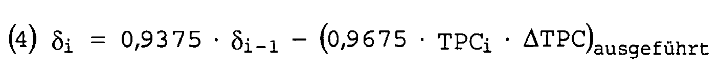
D.h., es wird für die δ-Formel nicht die befohlene Sendeleistungsänderung, sondern die tatsächlich durchgeführte Sendungsleistungsänderung verwendet.That is, for the δ-formula, not the commanded transmission power change but the actual transmission power change is used.
Claims (7)
- Method for controlling the transmission power in a radio system, in which- a transmission signal is transmitted by a transmitter (MS),- the transmission signal from the transmitter is received and evaluated by a receiver (BS) in order as a function of this to produce a power control command for controlling the transmission power of the transmitter and to transmit this to the transmitter, and- the transmission power of the transmitter is set on the basis of an estimated value (δ) after the occurrence of a transmission gap in the transmission channel which is defined between the transmitter and the receiver or between the receiver and the transmitter, which estimated value takes account of power control commands produced for the transmitter in the past, with the estimated value being determined as a function of a parameter (k) which indicates whether the respective power control command is or is not intended to be taken into account in the determination of the estimated value,characterized
in that the parameter for a second power control command is set to a value which results in the second power control command not being taken into account when determining the estimated value, under the condition thata) the second power control command directly succeeds a first power control command, andb) both power control commands would result in the transmission power of the transmitter reaching or exceeding a predetermined upper limit value (Pmax) or reaching or falling below a predetermined lower limit value (Pmin). - Method according to the preceding claim,
characterized
in that the parameter for the first power control command is set to a value which results in this power control command being taken into account when determining the estimated value if the first power control command directly succeeds a further power control command which would result in the transmission power of the transmitter not reaching or exceeding or falling below the same limit value. - Method according to either of the preceding claims,
characterized
in that the estimated value δi at the time i is calculated using the following recursive formula:
- Method according to Claim 3,
characterized
in that the parameter k is set to k=1 for the first power control command. - Method according to either of the two preceding claims,
characterized
in that the parameter k is set to k=0 for the second power control command. - Method according to one of the preceding claims,
characterized
in that the estimated value (δ) is a power control estimated value, with the transmission power control for the transmitter (MS) being set on the basis of the power control estimated value after the occurrence of a transmission gap. - Transmitting apparatus for a radio system,
in which the transmitting apparatus (MS) is designed such that it receives power control commands which are transmitted from another transmitting apparatus (BS) in the radio system, and uses them to control its own transmission power, and
in which the transmitting apparatus is designed such that it readjusts its transmission power control on the basis of an estimated value (δ) after the occurrence of a transmission gap in the transmission channel which is defined between the transmitter and the receiver (BS) or between the receiver and the transmitter, which estimated value (δ) takes account of power control commands produced for the transmitter in the past, with the estimated value being determined in the transmitter as a function of a parameter (k) which indicates for each transmission power control whether the corresponding power control command should or should not be taken into account when determining the estimated value,
characterized
in that the transmitting apparatus (MS) is designed to carry out a method according to one of the preceding method claims.
Applications Claiming Priority (3)
| Application Number | Priority Date | Filing Date | Title |
|---|---|---|---|
| DE10040228A DE10040228A1 (en) | 2000-08-17 | 2000-08-17 | Method for regulating the transmission power in a radio system |
| DE10040228 | 2000-08-17 | ||
| EP01962618A EP1307975B1 (en) | 2000-08-17 | 2001-08-08 | Method for regulating the transmission power in a radio communications system |
Related Parent Applications (2)
| Application Number | Title | Priority Date | Filing Date |
|---|---|---|---|
| EP01962618A Division EP1307975B1 (en) | 2000-08-17 | 2001-08-08 | Method for regulating the transmission power in a radio communications system |
| EP01962618A Division-Into EP1307975B1 (en) | 2000-08-17 | 2001-08-08 | Method for regulating the transmission power in a radio communications system |
Publications (2)
| Publication Number | Publication Date |
|---|---|
| EP1501207A1 EP1501207A1 (en) | 2005-01-26 |
| EP1501207B1 true EP1501207B1 (en) | 2017-03-22 |
Family
ID=7652752
Family Applications (2)
| Application Number | Title | Priority Date | Filing Date |
|---|---|---|---|
| EP01962618A Expired - Lifetime EP1307975B1 (en) | 2000-08-17 | 2001-08-08 | Method for regulating the transmission power in a radio communications system |
| EP04025574.7A Expired - Lifetime EP1501207B1 (en) | 2000-08-17 | 2001-08-08 | Method for regulating the transmit power in a radio system |
Family Applications Before (1)
| Application Number | Title | Priority Date | Filing Date |
|---|---|---|---|
| EP01962618A Expired - Lifetime EP1307975B1 (en) | 2000-08-17 | 2001-08-08 | Method for regulating the transmission power in a radio communications system |
Country Status (7)
| Country | Link |
|---|---|
| US (1) | US7062288B2 (en) |
| EP (2) | EP1307975B1 (en) |
| JP (1) | JP3709188B2 (en) |
| KR (1) | KR100564211B1 (en) |
| CN (1) | CN1230998C (en) |
| DE (2) | DE10040228A1 (en) |
| WO (1) | WO2002015431A2 (en) |
Families Citing this family (30)
| Publication number | Priority date | Publication date | Assignee | Title |
|---|---|---|---|---|
| US6829468B2 (en) | 2001-03-05 | 2004-12-07 | Lucent Technologies Inc. | Reverse-link power control overshoot considering mobile station transmission limitations |
| DE10306170A1 (en) * | 2003-02-13 | 2004-09-02 | Siemens Ag | Method for setting the transmission powers of two channels of a connection, station and communication system |
| EP1605605B1 (en) * | 2004-06-09 | 2019-02-27 | Samsung Electronics Co., Ltd. | Method and apparatus for data transmission in a mobile telecommunication system supporting enhanced uplink service |
| US8452316B2 (en) | 2004-06-18 | 2013-05-28 | Qualcomm Incorporated | Power control for a wireless communication system utilizing orthogonal multiplexing |
| US7197692B2 (en) | 2004-06-18 | 2007-03-27 | Qualcomm Incorporated | Robust erasure detection and erasure-rate-based closed loop power control |
| US8897828B2 (en) | 2004-08-12 | 2014-11-25 | Intellectual Ventures Holding 81 Llc | Power control in a wireless communication system |
| TWI454080B (en) * | 2004-09-09 | 2014-09-21 | 高通公司 | Device system and method for managing transmission power in a wireless communication system |
| US7899480B2 (en) * | 2004-09-09 | 2011-03-01 | Qualcomm Incorporated | Apparatus, system, and method for managing transmission power in a wireless communication system |
| US8848574B2 (en) | 2005-03-15 | 2014-09-30 | Qualcomm Incorporated | Interference control in a wireless communication system |
| US8942639B2 (en) | 2005-03-15 | 2015-01-27 | Qualcomm Incorporated | Interference control in a wireless communication system |
| CN101331698B (en) | 2005-10-27 | 2012-07-18 | 高通股份有限公司 | Method and apparatus for estimating reverse link loading in a wireless communication system |
| US7808956B2 (en) * | 2006-03-31 | 2010-10-05 | Motorola, Inc. | Dynamic, adaptive power control for a half-duplex wireless communication system |
| US20080045260A1 (en) * | 2006-08-15 | 2008-02-21 | Tarik Muharemovic | Power Settings for the Sounding Reference signal and the Scheduled Transmission in Multi-Channel Scheduled Systems |
| US20080117849A1 (en) * | 2006-09-08 | 2008-05-22 | Qualcomm Incorporated | Method and apparatus for interaction of fast other sector interference (osi) with slow osi |
| US8670777B2 (en) | 2006-09-08 | 2014-03-11 | Qualcomm Incorporated | Method and apparatus for fast other sector interference (OSI) adjustment |
| WO2009049326A1 (en) * | 2007-10-11 | 2009-04-16 | Nextivity, Inc. | Repeater for use in a cdma unii link |
| US20090219916A1 (en) * | 2008-02-29 | 2009-09-03 | Motorola, Inc. | Method to scan for critical transmissions while transmitting on a conventional time division multiple access channel |
| US9094918B2 (en) * | 2012-06-18 | 2015-07-28 | Qualcomm Incorporated | Apparatus and methods for efficient power control for tune away mode in a DSDS device |
| JP6014421B2 (en) * | 2012-08-30 | 2016-10-25 | 株式会社Nttドコモ | Base station and transmission power control method |
| US9871544B2 (en) | 2013-05-29 | 2018-01-16 | Microsoft Technology Licensing, Llc | Specific absorption rate mitigation |
| US10893488B2 (en) | 2013-06-14 | 2021-01-12 | Microsoft Technology Licensing, Llc | Radio frequency (RF) power back-off optimization for specific absorption rate (SAR) compliance |
| US9813997B2 (en) | 2014-01-10 | 2017-11-07 | Microsoft Technology Licensing, Llc | Antenna coupling for sensing and dynamic transmission |
| US10044095B2 (en) | 2014-01-10 | 2018-08-07 | Microsoft Technology Licensing, Llc | Radiating structure with integrated proximity sensing |
| US9769769B2 (en) | 2014-06-30 | 2017-09-19 | Microsoft Technology Licensing, Llc | Detecting proximity using antenna feedback |
| US9785174B2 (en) * | 2014-10-03 | 2017-10-10 | Microsoft Technology Licensing, Llc | Predictive transmission power control for back-off |
| US9871545B2 (en) | 2014-12-05 | 2018-01-16 | Microsoft Technology Licensing, Llc | Selective specific absorption rate adjustment |
| US10044459B2 (en) * | 2015-11-04 | 2018-08-07 | Qualcomm Incorporated | Uplink control signaling on a shared communication medium |
| US10013038B2 (en) | 2016-01-05 | 2018-07-03 | Microsoft Technology Licensing, Llc | Dynamic antenna power control for multi-context device |
| US10461406B2 (en) | 2017-01-23 | 2019-10-29 | Microsoft Technology Licensing, Llc | Loop antenna with integrated proximity sensing |
| US10224974B2 (en) | 2017-03-31 | 2019-03-05 | Microsoft Technology Licensing, Llc | Proximity-independent SAR mitigation |
Family Cites Families (4)
| Publication number | Priority date | Publication date | Assignee | Title |
|---|---|---|---|---|
| JP3755704B2 (en) | 1997-12-27 | 2006-03-15 | ソニー株式会社 | Transmission power control method, base station apparatus and communication terminal apparatus |
| DE19821519C2 (en) | 1998-05-13 | 2001-08-09 | Siemens Ag | Method for operating a wireless telecommunication device in particular indoors |
| US6885875B1 (en) | 1998-10-09 | 2005-04-26 | Siemens Aktiengesellschaft | Method and radio communication system for regulating power between a base station and a subscriber station |
| EP1079541B1 (en) * | 1999-08-23 | 2005-04-13 | Alcatel | Method for improving mobile radiocommunication system performances using a power control algorithm |
-
2000
- 2000-08-17 DE DE10040228A patent/DE10040228A1/en not_active Withdrawn
-
2001
- 2001-08-08 US US10/362,245 patent/US7062288B2/en not_active Expired - Lifetime
- 2001-08-08 EP EP01962618A patent/EP1307975B1/en not_active Expired - Lifetime
- 2001-08-08 KR KR1020037002299A patent/KR100564211B1/en not_active Expired - Lifetime
- 2001-08-08 CN CNB018139582A patent/CN1230998C/en not_active Expired - Lifetime
- 2001-08-08 JP JP2002520437A patent/JP3709188B2/en not_active Expired - Lifetime
- 2001-08-08 DE DE50104982T patent/DE50104982D1/en not_active Expired - Lifetime
- 2001-08-08 WO PCT/DE2001/003029 patent/WO2002015431A2/en not_active Ceased
- 2001-08-08 EP EP04025574.7A patent/EP1501207B1/en not_active Expired - Lifetime
Non-Patent Citations (1)
| Title |
|---|
| None * |
Also Published As
| Publication number | Publication date |
|---|---|
| EP1307975A2 (en) | 2003-05-07 |
| DE10040228A1 (en) | 2002-02-28 |
| CN1446412A (en) | 2003-10-01 |
| EP1501207A1 (en) | 2005-01-26 |
| US7062288B2 (en) | 2006-06-13 |
| KR20030027954A (en) | 2003-04-07 |
| WO2002015431A3 (en) | 2002-05-23 |
| US20030186718A1 (en) | 2003-10-02 |
| EP1307975B1 (en) | 2004-12-29 |
| JP3709188B2 (en) | 2005-10-19 |
| CN1230998C (en) | 2005-12-07 |
| JP2004507150A (en) | 2004-03-04 |
| WO2002015431A2 (en) | 2002-02-21 |
| KR100564211B1 (en) | 2006-03-28 |
| DE50104982D1 (en) | 2005-02-03 |
Similar Documents
| Publication | Publication Date | Title |
|---|---|---|
| EP1501207B1 (en) | Method for regulating the transmit power in a radio system | |
| DE69913232T3 (en) | Method and system for transmission power control during macrodiversity | |
| DE19725438B4 (en) | Control of transmission performance in wireless packet data transmission | |
| DE69923166T2 (en) | A method of enhancing the performance of a mobile radio communication system using a power control algorithm | |
| DE69108793T2 (en) | Method for controlling the performance in a digital mobile radio communication system. | |
| DE69625009T2 (en) | Method for controlling the transmission power of a radio transmitter | |
| DE69826898T2 (en) | METHOD FOR TRAFFIC LOAD CONTROL IN A TELECOMMUNICATIONS NETWORK | |
| DE69431648T2 (en) | METHOD AND DEVICE FOR CONTROLLING TRANSMITTER POWER IN A RADIO | |
| DE602004000811T2 (en) | Method and apparatus for increased efficiency of a power amplifier in radio transmission systems with high power factor factors | |
| DE60132848T2 (en) | Method for transmission power control in a mobile radio communication system | |
| DE69915811T2 (en) | Method for improving the performance of a mobile radio communication system while determining the convergence of the power control loop | |
| DE69735320T3 (en) | Transmission power control for the downlink of a mobile communication system with site diversity | |
| DE69112974T2 (en) | Method for regulating the output power in a mobile radio communication system. | |
| EP1188256B9 (en) | Method for adjusting transmission power in a radio system and corresponding radio system | |
| DE69837325T2 (en) | Method and device for transmission power control in a communication system | |
| DE69909574T2 (en) | METHOD AND DEVICE FOR CONTROLLING TRANSMITTER POWER FROM AN INTERRUPTED FRAME | |
| DE69924722T2 (en) | A method of enhancing the performance of a mobile radio communication system using a power control algorithm | |
| DE69919519T2 (en) | A method for improving the performance of a mobile radio communication system using a power control algorithm | |
| DE69934209T2 (en) | A method for improving the characteristics of a mobile radio communication system using a power control algorithm | |
| EP1383235B1 (en) | Method and apparatus for operating a transmission amplifier | |
| EP1058407A1 (en) | Transmit power correction in a mobile communication system | |
| DE60317807T2 (en) | A method for improving the performance of a mobile radio communication system using a power control algorithm | |
| EP1310050B1 (en) | Method for controlling transmitting power in a radio system | |
| EP1290813B1 (en) | Method for regulating the transmitting power of a transmit station, and corresponding transmit station | |
| EP1320946B1 (en) | Method for controlling the transmitting power in a radio system and a corresponding transmitting device |
Legal Events
| Date | Code | Title | Description |
|---|---|---|---|
| PUAI | Public reference made under article 153(3) epc to a published international application that has entered the european phase |
Free format text: ORIGINAL CODE: 0009012 |
|
| AC | Divisional application: reference to earlier application |
Ref document number: 1307975 Country of ref document: EP Kind code of ref document: P |
|
| AK | Designated contracting states |
Kind code of ref document: A1 Designated state(s): DE FR GB |
|
| 17P | Request for examination filed |
Effective date: 20050209 |
|
| AKX | Designation fees paid |
Designated state(s): DE FR GB |
|
| 17Q | First examination report despatched |
Effective date: 20071018 |
|
| RAP1 | Party data changed (applicant data changed or rights of an application transferred) |
Owner name: SIEMENS AKTIENGESELLSCHAFT |
|
| RAP1 | Party data changed (applicant data changed or rights of an application transferred) |
Owner name: SIEMENS AKTIENGESELLSCHAFT |
|
| GRAP | Despatch of communication of intention to grant a patent |
Free format text: ORIGINAL CODE: EPIDOSNIGR1 |
|
| INTG | Intention to grant announced |
Effective date: 20161018 |
|
| GRAS | Grant fee paid |
Free format text: ORIGINAL CODE: EPIDOSNIGR3 |
|
| GRAA | (expected) grant |
Free format text: ORIGINAL CODE: 0009210 |
|
| AC | Divisional application: reference to earlier application |
Ref document number: 1307975 Country of ref document: EP Kind code of ref document: P |
|
| AK | Designated contracting states |
Kind code of ref document: B1 Designated state(s): DE FR GB |
|
| REG | Reference to a national code |
Ref country code: GB Ref legal event code: FG4D Free format text: NOT ENGLISH |
|
| REG | Reference to a national code |
Ref country code: DE Ref legal event code: R096 Ref document number: 50116616 Country of ref document: DE |
|
| REG | Reference to a national code |
Ref country code: FR Ref legal event code: PLFP Year of fee payment: 17 |
|
| RAP2 | Party data changed (patent owner data changed or rights of a patent transferred) |
Owner name: SIEMENS AKTIENGESELLSCHAFT |
|
| REG | Reference to a national code |
Ref country code: DE Ref legal event code: R097 Ref document number: 50116616 Country of ref document: DE |
|
| PLBE | No opposition filed within time limit |
Free format text: ORIGINAL CODE: 0009261 |
|
| STAA | Information on the status of an ep patent application or granted ep patent |
Free format text: STATUS: NO OPPOSITION FILED WITHIN TIME LIMIT |
|
| 26N | No opposition filed |
Effective date: 20180102 |
|
| REG | Reference to a national code |
Ref country code: FR Ref legal event code: PLFP Year of fee payment: 18 |
|
| PGFP | Annual fee paid to national office [announced via postgrant information from national office to epo] |
Ref country code: GB Payment date: 20200916 Year of fee payment: 20 Ref country code: FR Payment date: 20200813 Year of fee payment: 20 |
|
| PGFP | Annual fee paid to national office [announced via postgrant information from national office to epo] |
Ref country code: DE Payment date: 20201019 Year of fee payment: 20 |
|
| REG | Reference to a national code |
Ref country code: DE Ref legal event code: R071 Ref document number: 50116616 Country of ref document: DE |
|
| REG | Reference to a national code |
Ref country code: GB Ref legal event code: PE20 Expiry date: 20210807 |
|
| PG25 | Lapsed in a contracting state [announced via postgrant information from national office to epo] |
Ref country code: GB Free format text: LAPSE BECAUSE OF EXPIRATION OF PROTECTION Effective date: 20210807 |