Field of the Invention
This invention relates to imageable elements. In particular, this invention
relates thermally imageable elements useful as on-press developable
lithographic printing plate precursors.
Background of the Invention
In conventional lithographic printing, ink receptive regions, known as
image areas, are present on a hydrophilic surface. When the surface is
moistened with water and ink is applied, the hydrophilic regions retain the water
and repel the ink, and the ink receptive regions accept the ink and repel the
water. The ink is transferred to the surface of a material upon which the image is
to be reproduced. Typically, the ink is first transferred to an intermediate blanket,
which in turn transfers the ink to the surface of the material upon which the image
is to be reproduced.
Imageable elements useful as lithographic printing plate precursors
typically comprise a layer of an imageable composition applied over the
hydrophilic surface of a substrate. The layer of imageable composition typically
comprises one or more radiation-sensitive components, which may be dispersed
in a suitable binder. Alternatively, the radiation-sensitive component can also be
the binder material. If, after imaging, the imaged regions of the layer of
imageable composition are removed to reveal the underlying hydrophilic surface
of the substrate, the precursor is positive working. Conversely, if the unimaged
regions are removed, the precursor is negative-working. In each instance, the
regions that remain (i.e., the image areas) are ink-receptive, and the revealed
regions of the hydrophilic surface accept water and aqueous solutions, typically a
fountain solution, and repel ink.
Imageable elements useful as on-press developable lithographic printing
plate precursors have been disclosed in the literature. Such elements can be
directly mounted on a press after imaging and developed with ink and/or fountain
solution during the initial press operation. A separate development step before
mounting on press is not required. On-press developable lithographic printing
plate precursors are discussed, for example, in Teng, U.S. Pat. No. 6,071,675,
column 2, line 47, to column 3, line 17.
Imaging of the imageable element with ultraviolet and/or visible radiation is
typically carried out through a mask, which has clear and opaque regions.
Imaging takes place in the regions under the clear regions of the mask but does
not occur in the regions under the opaque regions. If corrections are needed in
the final image, a new mask must be made. This is a time-consuming process.
In addition, dimensions of the mask may change slightly due to changes in
temperature and humidity. Thus, the same mask, when used at different times or
in different environments, may give different results and could cause registration
problems.
Direct digital imaging, which obviates the need for imaging through a
mask, is becoming increasingly important in the printing industry. Imageable
elements for the preparation of lithographic printing plates have been developed
for use with infrared lasers. Despite the progress in conventional on-press
developable plates and digital laser imaginable plates, there is a desire for a
lithographic plate precursor that can be imaged by infrared laser, does not
produce ablation debris, and does not require a separate liquid development
process. More specifically, there is a desire for thermally imageable elements
that are on-press developable with ink and/or fountain solution.
Summary of the Invention
In one aspect, the invention is an imageable element comprising:
in which: the imageable composition comprises:
a photothermal conversion material, and particles of a polyurethane polymer; the polyurethane polymer comprises urethane linkages in the main chain;
and the polyurethane polymer does not comprise side chain urethane groups.
In another aspect, the invention is a method for forming an image useful
as a lithographic printing plate by imaging the imageable element and developing
the imaged imageable element with ink and/or fountain solution.
Detailed Description of the Invention
Unless the context indicates otherwise, in the specification and claims, the
terms diisocyanate, photothermal conversion material, polyurethane polymer,
binder, dihydroxy compound, diisocyanate, and similar terms include mixtures of
such materials. Unless otherwise specified, all percentages are percentages by
weight. Thermal imaging refers to imaging either with a hot body or with an
infrared laser.
Imageable Element
The imageable element comprises a layer of an imageable composition
over a support. The imageable composition comprises a photothermal
conversion material and particles that comprise a polyurethane polymer. A water
soluble binder may also be present. Typically, the layer of imageable
composition has a dry coating weight of about 0.5 to about 4 g/m2, preferably 0.7
to 3 g/m2.
Polyurethane Polymer Particles
The polyurethane polymer has urethane groups in the polymer backbone.
The polyurethane polymer does not have side chain urethane groups or linkages.
In one aspect of the invention, the polyurethane polymer is not crosslinked.
Preferably, at least one of the ends of the polyurethane polymer is an isocyanate
group. More preferably, both ends are isocyanate groups. The terminal
isocyanate group or groups may be capped with blocking groups or converted to
amine groups by aqueous treatment.
The polyurethane polymer may be prepared by reaction of a diisocyanate
or a dimer or adduct thereof, with a dihydroxy compound. Diisocyanates can be
represented by the formula Y(NCO)2, in which Y is a substituted or unsubstituted
bivalent aliphatic or aromatic group. Any diisocyanate may be used to prepare
the polyurethane polymer. Examples of useful diisocyanates include aliphatic
and cycloaliphatic diisocyanates, such as 4,4-methylenebisdicyclohexyl
diisocyanate (hydrogenated MDI), 1,4-tetramethylene diisocyanate, 1,6-hexamethylene
diisocyanate (HDI), isophorone diisocyanate (IPDI),
methylenebis(cyclohexyl isocyanate), trimethyl hexamethylene diisocyanate
(TMDI), meta-tetramethylxylylene diisocyanate (TMXDI), and 1,4-cyclohexyl
diisocyanate; aromatic diisocyanates, such as tolylene diisocyanate (TDI) (i.e.,
2,4-tolylene diisocyanate, 2,6-tolylene diisocyanate, or a mixture thereof), 4,4-diphenylmethane
diisocyanate (MDI), 2,4'-diphenylmethane diisocyanate, 2,2'-diphenylmethane
diisocyanate, 4,4'-diphenyl ether diisocyanate, naphthalene-1,5-diisocyanate
(NDI), 3,3-dimethyl-4,4-biphenylene diisocyanate (TODI), crude
TDI (i.e., a mixture of TDI and an oligomer thereof), polymethylenepolyphenyl
polyisocyanate, crude MDI (i.e., a mixture of MDI and an oligomer thereof),
xylylene diisocyanate (XDI), tetramethyl xylylene diisocyanate, and phenylene
diisocyanate; and dimers thereof, adducts thereof with diols, and mixtures
thereof. A preferred diisocyanate is isophorone diisocyanate.
Typical dihydroxy compounds include for example: aromatic compounds
having two hydroxyl groups, such as hydroquinone, resorcinol, catechol,
methylhydroquinone, ethylhydroquinone, 2,3-dimethylhydroquinone, 2,4-dihydroxybenzoic
acid, 3,5-dihydroxybenzoic acid, 1,5-dihydroxynaphthalene,
and 2,6-dihydroxynaphthalene; bisphenols, such as 4,4'-dihydroxybiphenyl (4,4'-diphenol),
2,2'-dihydroxybiphenyl (2,2'-diphenol), bisphenol A (2,2-bis(4-hydroxyphenyl)propane),
bisphenol AF (1,1,1,3,3,3,-hexafluro-2,2-bis(4-hydroxyphenyl)propane),
bisphenol E (2,2-bis(4-hydroxyphenyl)ethane), and 4,4'-dihydroxybenzophenone;
diols, such as ethylene glycol, diethylene glycol,
triethylene glycol, polyethylene glycol, 1,2-propanediol, 1,3-propaone diol, 1,2-butanediol,
1,4-butanediol, 2,2-dimethyl-1,3-propanediol (neopentyl glycol), 1,5-pentanediol,
2-methyl-1,5-pentanediol, 3-methyl-1,5-pentanediol, 1,6-hexanediol,
1,8-octanediol, 1,9-nonanediol, 2,2-diethyl-1,3-propanediol, 2-n-butyl-2-ethyl-1,3-propanediol,
2,2,4 -trimethyl-1,3-pentanediol, 2-ethyl-1,3-hexanediol, and 1,2-cyclohexanediol;
and carboxyl functional diols, for example, dialkanol alkanoic
acids, such as 2,2-bis(hydroxymethyl) propionic acid (2,2-dimethylol propanoic
acid), 2,2-bis(2-hydroxyethyl) propionic acid, 2,2-bis(3-hydroxypropyl) propionic
acid, bis(hydroxymethyl)acetic acid, bis(4-hydroxyphenyl)acetic acid, 2,2-bis(hydroxymethyl)
butyric acid, 2,2-bis(hydroxymethyl) pentanoic acid, and
tartaric acid; dihydroxybenzoic acids such as 3,5-dihydroxybenzoic acid; and
dihydroxy dicarboxylic acids derived from the reaction of dianhydrides with diols,
such as the reaction product of a dianhydride such as pyromellitic dianhydride,
3,3',4,4'-benzophenone tetracarboxylic dianhydride, 3,3',4,4'-diphenyl
tetracarboxylic dianhydride, or 2,3,6,7-naphthalene tetracarboxylic dianhydride
with a diol such as those listed above.
Mixtures of dihydroxy compounds may be used. Typical mixtures
comprise about 1-25% of a carboxy functional diol or a mixture of carboxy
functional diols, with the remainder of the mixture comprising an aromatic diol or
mixture of aromatic diols and/or an aliphatic diol or mixture of aliphatic diols.
Preferably, the dihydroxy compound comprises about 3-15% of a carboxy
functional diol or a mixture of carboxy functional diols, about 0-50% of an
aromatic diol or mixture of aromatic diols, and about 35-97% of an aliphatic diol
or a mixture of aliphatic diols.
The polyurethane polymers may be prepared by conventional methods.
The diisocyanate or mixture of diisocyanates and the dihydroxy compound or
mixture of dihydroxy compounds are mixed together in a solvent. The solvent
should not react with the diisocyanate and should not contain impurities, such as
water, that can react with the diisocyanate. Suitable solvents include, for
example, methyl acetate, ethyl acetate, amyl acetate, acetone, methyl ethyl
ketone, diethyl ketone, 4-methyl-2-pentanone, dimethyl formamide, dioxane, and
methyl pyrrolidone. The reaction is carried out under anhydrous conditions,
typically at about 40°C to about 90°C for several hours. A catalyst, such as
about 0.5% or less, typically about 0.04% of, for example, dibutyl tin dilaurate
may be added.
The polyurethane polymer may, or may not, comprise blocking groups. If
no blocking groups are to be present in the polyurethane polymer, equimolar
amounts of the diisocyanate or mixture of diisocyanates and the dihydroxy
compound or mixture of dihydroxy compounds are mixed together in the solvent.
Blocking agents include, for example, alcohols such as methanol, ethanol;
and 2-propanol; glycol ethers, such as 2-methoxyethanol, 2-ethoxyethanol, 2-(2-methoxy)ethoxyethanol,
and 3-ethoxyethanol; phenols, such as, phenol and
cresols; oximes, for example, C2 to C8 alkanone oximes, such as, acetone oxime
and butanone oxime, and benzophenone oxime; thiophenols; organic carbanion
active hydrogen compounds, such as diethyl malonate, acetylacetone, ethyl
acetoacetate, and ethyl cyanoacetate; and primary and secondary amines, such
as butyl amine, diethyl amine, and 3-amino-1,2,4-triazole; and hydroxylamine.
If blocking groups are to be present in the polyurethane polymer, an about
10% molar excess of the diisocyanate or mixture of diisocyanates is used. After
the reaction of the diisocyanate or mixture of diisocyanates with the dihydroxy
compound or mixture of dihydroxy compounds is essentially complete, the
blocking agent is added and heating continued for several hours. Alternatively, if
amino end groups are desired, the mixture can be subjected to an aqueous
treatment, such as an aqueous workup, after the reaction of the diisocyanate or
mixture of diisocyanates with the dihydroxy compound or mixture of dihydroxy
compounds is essentially complete.
To form particles of the polyurethane polymer, additional solvent, if
necessary, is added to the reaction mixture to form a clear solution of the
polymer. The resulting polymer solution is washed with base and with water.
Then a volume of water about equal to the volume of the polymer solution and,
optionally, a surfactant, is added and the resulting mixture passed through a high
shear device such as a high speed mixer, chemical blender, high pressure
homogenizer, or microfluidizer. The solvent in which the polymer is dissolved is
evaporated to give an aqueous dispersion of polyurethane polymer particles.
The particles typically have a diameter of 0.001-1 micrometers, preferably
a diameter of 0.01-0.5 micrometers.
Photothermal Conversion Material
The imageable element comprises an infrared absorber, known as a
photothermal conversion material. Photothermal conversion materials absorb
radiation and convert it to heat. Although a photothermal conversion material is
not necessary for imaging with a hot body, imageable elements that contain a
photothermal conversion material may also be imaged with a hot body, such as a
thermal head or an array of thermal heads.
The photothermal conversion material may be either a dye or pigment,
such as a dye or pigment of the squarylium, merocyanine, indolizine, pyrylium, or
metal diothiolene class. Examples of absorbing pigments are Projet 900, Projet
860 and Projet 830 (all available from the Zeneca Corporation), and carbon
black. The photothermal conversion material may be, for example, an
indoaniline dye, an oxonol dye, a porphyrin derivative, an anthraquinone dye, a
merostyryl dye, a pyrylium compound, or a squarylium derivative with the
appropriate absorption spectrum and solubility.
Dyes, especially dyes with a high extinction coefficient in the range of 750
nm to 1200 nm, are preferred. Absorbing dyes are disclosed in numerous
publications, for example, Nagasaka, EP 0,823,327; DeBoer, U.S. Pat. No.
4,973,572; Jandrue, U.S. Pat. No. 5,244,771; and Chapman, U.S. Pat. No.
5,401,618. Examples of useful cyanine dyes include: 2-[2-[2-phenylsulfonyl-3-[2-(1,3-dihydro-1,3,3-trimethyl-2H-indol-2-ylidene)-ethylidene]-1-cyclohexen-1-yl]-ethenyl]-1,3,3-trimethyl-3H-indolium
chloride; 2-[2-[2-thiophenyl-3-[2-(1,3-dihydro-1,3,3-trimethyl-2H-indol-2-ylidene)-ethylidene]-1-cyclohexen-1-yl]-ethenyl]-1,3,3-trimethyl-3H-indolium
chloride; 2-[2-[2-thiophenyl-3-[2-(1,3-dihydro-1,3,3-trimethyl-2H-indol-2-ylidene)-ethylidene]-1-cyclopenten-1-yl]-ethenyl]-1,3,3-trimethyl-3H-indolium
tosylate; 2-[2-[2-chloro-3-[2-ethyl-(3H-benzthiazole-2-ylidene)-ethylidene]-l
-cyclohexen-1-yl]-ethenyl]-3-ethyl-benzthiazolium
tosylate; and 2-[2-[2-chloro-3-[2-(1,3-dihydro-1,3,3-trimethyl-2H-indol-2-ylidene)-ethylidene]-1-cyclohexen-1-yl]-ethenyl]-1,3,3-trimethyl-3H-indolium
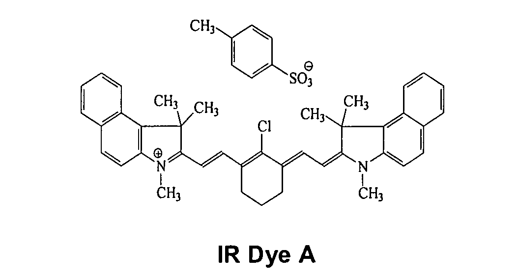
tosylate. Other examples of useful absorbing dyes include: ADS-830A
and ADS-1 064 (American Dye Source, Montreal, Canada), EC2117 (FEW,
Wolfen, Germany), Cyasorb IR 99 and Cyasorb IR 165 (Glendale Protective
Technology), Epolite IV-62B and Epolite III-178 (Epoline),. PINA-780 (Allied
Signal), SpectralR 830A and SpectralR 840A (Spectra Colors), as well as IR Dye
A, and IR Dye B.

Other useful photothermal conversion materials include infrared absorbers
of Structure I, Structure II, and Structure III. These photothermal conversion
materials absorb in two different regions of the infrared spectrum so elements
that comprise these materials can be imaged with imaging devices that contain
lasers that emit either at about 830 nm, at about 1056 nm, or at about 1064 nm.
in which:
Infrared absorbers of Structure I, Structure II, or Structure III may be
prepared by mixing a solution of a salt that contains the desired cation with a
solution of a salt that contains the desired anion and filtering off the resulting
precipitate. The anion of the salt that contains the desired cation is typically, for
example, a sulfate, bisulfate, or halide, such as chloride or bromide. The cation
of the salt that contains the desired anion is typically ammonium, substituted
ammonium such as trimethyl ammonium or tri-n-butyl ammonium, lithium,
sodium, or potassium. The solvent may be water or a solvent including a mixture
of water and a hydrophilic solvent such an as alcohol, for example methanol,
ethanol, or propylene glycol methyl ether.
The amount of infrared absorber in the imageable composition is generally
sufficient to provide an optical density of at least 0.05, and preferably, an optical
density of from about 0.5 to at least about 2 to 3 at the imaging wavelength. As
is well known to those skilled in the art, the amount of compound required to
produce a particular optical density can be determined from the thickness of the
underlayer and the extinction coefficient of the infrared absorber at the
wavelength used for imaging using Beer's law.
Other Ingredients
Optionally, the imageable layer may also comprise a water soluble
polymer, or binder. For water solubility, the binder should not be cross-linked.
Typical water soluble polymers are polyvinyl alcohol and its water soluble
derivatives and co-polymers, such as partially hydrolyzed polyvinyl acetate and
ethylene/vinyl alcohol co-polymers; poly(meth)acrylic acid; poly(meth)acrylamide;
polyacrylamide, polyacrylic acid, polyhydroxyethyl(meth)acrylate;
polyvinyl methylether; polyethylene oxide; poly-N-vinyl pyrrolidone, polyvinyl
imidazole, polyvinyl pyrazole, polyacrylamide, polyacrylic acid, and water soluble
derivatives and copolymers thereof, gelatin, and cellulose derivatives such as
hydroxyalkyl cellulose and carboxymethyl cellulose. Preferred water soluble
polymers are polyvinyl alcohol and its water soluble derivatives and co-polymers.
Other ingredients that are conventional components of imageable
compositions, such as dyes and surfactants, may be present. Surfactants may
be present in the imageable composition as, for example, coating aids. A dye
may be present to aid in the visual inspection of the imaged and/or developed
element. Printout dyes distinguish the imaged regions from the unimaged
regions during processing. Contrast dyes distinguish the unimaged regions from
the imaged regions in the developed imageable element. Preferably, the dye
does not absorb the imaging radiation. Triarylmethane dyes, such as ethyl violet,
crystal violet, malachite green, brilliant green, Victoria blue B, Victoria blue R,
Victoria pure blue BO, and D11 (PCAS, Longjumeau, France), may act as the
contrast dye.
Composition
When a water soluble polymer or mixture of water soluble polymers is not
present, the imageable layer typically comprises about 80% to about 99%,
preferably about 85% to about 95%, of the polyurethane particles, based on the
dry weight of the particles; typically about 0.01% to about 5%, preferably about
0.1% to about 1%, of the surfactant or mixture of surfactants; and typically about
0.5% to about 20%, preferably about 1% to about 15%, of the infrared absorber
or mixture of infrared absorbers.
When a water soluble polymer or mixture of water soluble polymers is
present, the imageable layer typically comprises about 60% to about 95%,
preferably about 70% to about 90%, of the polyurethane particles, based on the
dry weight of the particles; typically about 0.01% to about 5%, preferably about
0.1% to about 1%, of the surfactant of mixture of surfactants; typically about
0.5% to 20%, preferably about 1% to about 15%, of the infrared absorber or
mixture of infrared absorbers; and typically about 3% to 30%, preferably about
5% to about 20%, of the water soluble polymer or mixture of water soluble
polymers.
Substrate
The imageable composition is coated over a substrate. The substrate
comprises a support, which may be any material conventionally used to prepare
imageable elements useful as lithographic printing plates. The support is
preferably strong, stable and flexible. It should resist dimensional change under
conditions of use so that color records will register in a full-color image.
Typically, it can be any self-supporting material, including, for example, polymeric
films such as polyethylene terephthalate film, ceramics, metals, or stiff papers, or
a lamination of any of these materials. Metal supports include aluminum, zinc,
titanium, and alloys thereof.
Typically, polymeric films contain a sub-coating on one or both surfaces to
modify the surface characteristics to enhance the hydrophilicity of the surface, to
improve adhesion to subsequent layers, to improve planarity of paper substrates,
and the like. The nature of this layer or layers depends upon the substrate and
the composition of subsequent coated layers. Examples of subbing layer
materials are adhesion-promoting materials, such as alkoxysilanes,
aminopropyltriethoxysilane, glycidoxypropyltriethoxysilane and epoxy functional
polymers, as well as conventional subbing materials used on polyester bases in
photographic films.
The surface of an aluminum support may be treated by techniques known
in the art, including physical graining, electrochemical graining, chemical
graining, and anodizing. The substrate should be of sufficient thickness to
sustain the wear from printing and be thin enough to wrap around a printing form,
typically from about 100 µm to about 600 µm. Typically, the substrate comprises
an interlayer between the aluminum support and the layer of imageable
composition. The interlayer may be formed by treatment of the support with, for
example, silicate, dextrine, hexafluorosilicic acid, phosphate/fluoride, polyvinyl
phosphonic acid (PVPA), or vinyl phosphonic acid copolymers.
The back side of the substrate (i.e., the side opposite the underlayer and
layer of imageable composition) may be coated with an antistatic agent and/or a
slipping layer or matte layer to improve handling and "feel" of the imageable
element.
Preparation of the Imageable Elements
The imageable element may be prepared by applying the layer of
imageable composition over the surface of the substrate using conventional
techniques. The terms "coating solvent" and "coating solution" are used although
some or all of the materials are be suspended or dispersed in the solvent rather
than in solution. The aqueous dispersion of the particles of polyurethane
polymer, the photothermal conversion material, and, if present, the water soluble
polymer and/or any other ingredients, are dissolved and/or dispersed in water to
form the coating solution. Other solvents that have at least some solubility with
water, such as 1-propanol, may be added to improve coating cosmetics and/or
improve the solubility of the components, such as the infrared absorber, in the
coating solution. The coating solution is coated onto the substrate by
conventional methods, such as spin coating, bar coating, gravure coating, die
coating, or roller coating. The water and any other solvents, if present, are
evaporated to produce the imageable element.
If desired, a protective overcoat that is removable by ink and/or fountain
solution, such as a layer of polyvinyl alcohol, may be coated over the layer of
imageable composition. The protective overcoat protects the element during
storage and handling, but is removed by ink and/or fountain solution, following
imaging.
Imaging and Processing
The element may be thermally imaged with a laser or an array of lasers
emitting modulated near infrared or infrared radiation in a wavelength region that
is absorbed by the imageable element. Infrared radiation, especially infrared
radiation in the range of about 800 nm to about 1200 nm, is typically used for
imaging. Imaging is conveniently carried out with a laser emitting at about 830
nm, about 1056 nm, or about 1064 nm. Alternatively, the imageable element
may be thermally imaged using a hot body, such as a conventional apparatus
containing a thermal printing head. Following imaging, it is developed on-press.
For on-press development, good quality prints should be obtained preferably
under 20 initial impressions, and more preferably under 5 impressions.
The imageable element may be imaged off press or on press. For off
press imaging, suitable commercially available imaging devices include image
setters such as the Creo Trendsetter (CREO, Burnaby, British Columbia,
Canada), the Screen PlateRite model 4300 and model 8600 (Screen, Rolling
Meadows, Chicago, Illinois, USA), and the Gerber Crescent 42T (Gerber). For
off press imaging with a hot body, the apparatus typically includes a thermal
head array, such as a TDK Model No. LV5416 used in thermal fax machines and
sublimation printers or the GS618-400 thermal plotter (Oyo Instruments,
Houston, TX, USA).
In conventional wet press lithographic printing, fountain solution and then
ink are applied to the printing plate. For presses with integrated
inking/dampening system, the ink and fountain solution are emulsified by various
press rollers before being transferred to the plate as emulsion of ink and fountain
solution. However, in this invention, the ink and fountain solution may be applied
in any combination or sequence, as needed for the plate. Typical ingredients of
aqueous fountain solutions, in addition to water, typically deionized water, include
pH buffering systems, such as phosphate and citrate buffers; desensitizing
agents, such as dextrin, gum arabic, and sodium carboxymethylcellulose;
surfactants and wetting agents, such as aryl and alkyl sulfonates, polyethylene
oxides, polypropylene oxides, and polyethylene oxide derivatives of alcohols and
phenols; humectants, such as glycerin and sorbitol; low boiling solvents such as
ethanol and 2-propanol; sequestrants, such as borax, sodium
hexametaphosphate, and salts of ethylenediamine tetraacetic acid; biocides,
such as isothiazolinone derivatives; and antifoaming agents. Numerous aqueous
fountain solutions are known to those skilled in the art. Fountain solutions are
disclosed, for example, in Matsumoto, U.S. Pat. No. 5,720,800; Archer, U.S. Pat.
No. 5,523,194; Chase, U.S. Pat. No. 5,279,648; Bondurant, U.S. Pat. Nos.
5,268,025, 5,336,302, 5,382,298, Egberg, U.S. Pat. No. 4,865,646; and
Daugherty, U.S. Pat. No. 4,604,952.
Lithographic printing inks typically comprise a colorant or mixture of
colorants, a vehicle, a solvent, and one or more additives, such as dispersing
agents. The inks are hydrophobic so they will be taken up by the hydrophobic
regions of the printing plate and are typically quite viscous. Typical colorants are
dyes and pigments, such as carbon black. Typical vehicles include, for example,
natural and processed resins such as drying oil, synthetic drying oil, rosin, copal,
dammer, shellac, hardened rosin and rosin esters, phenolic resins, rosin modified
phenolic resins, maleic acid resins, alkyd resins, acrylic resins, polyamide resins,
epoxy resins, aminoalkyd resins, and polyurethane resins. Typical solvents
include turpentine, mineral spirits, short chain esters, that is esters derived from
aliphatic acids having 2 to 6 carbon atoms and aliphatic alcohols having 2 to 6
carbon atoms, such as amyl acetate, and mixtures thereof. The solvent typically
has a boiling point of about 75°C to about 200°C so that it will not evaporate too
quickly from the ink containing the vehicle. Lithographic printing inks are
commercially available from a number of suppliers, including, for example, Sun
Chemical Ink, Northlake, IL, USA; Flint Ink, Ann Arbor, MI, USA; Graphic Ink
Company Inc., Salt Lake City, UT, USA; Gans Ink & Supply Co, Los Angeles,
CA, USA; and Van Son Holland Ink Corporation, Holland.
Imaging produces an imaged element, which comprises a latent image of
imaged regions and complementary unimaged regions. The imaged imageable
element is mounted on the plate cylinder of a lithographic press and developed
with ink and/or fountain solution by rotating the press cylinders and contacting
the plate with ink and/or fountain solution. The unimaged regions of the imaged
imageable element are removed by the ink and/or fountain solution
For on-press imaging, the imageable element is imaged while mounted on
a lithographic printing press cylinder, and the imaged imageable element is
directly developed on press with ink and/or fountain solution during initial press
operation. This is especially suitable for computer-to-press application in which
the imageable element (or elements, for multiple color press) is directly imaged
on the plate cylinder according to computer generated digital imaging information
and, with minimum or no treatment, directly prints out regular printed sheets. On-press
imaging may be carried out, for example on a Speedmaster 74 DI press or
a Quickmaster DI 46-4 press (Heidelberger Druckmaschinen, Heidelberg,
Germany).
INDUSTRIAL APPLICABILITY
The imageable elements are useful on-press developable lithographic
printing plate precursors. Once the imageable element has been imaged and
processed to form a printing plate, printing can be carried out by applying a
fountain solution and then a lithographic ink to the image on its surface. Fountain
solution is taken up by the surface of the substrate exposed by imaging and
development, and the ink is taken up by the complementary regions. The ink is
transferred to a suitable receiving material (such as cloth, paper, metal, glass or
plastic) either directly or indirectly using an offset printing blanket to provide a
desired impression of the image thereon.
The advantageous properties of this invention can be observed by
reference to the following examples, which illustrate but do not limit the invention.
EXAMPLES
In the Examples, "coating solution" refers to the mixture of solvent or
solvents and additives coated, even though some of the additives may be in
suspension rather than in solution. Except where indicated, the indicated
percentages are percentages by weight based on the total solids in the coating
solution.
Glossary
- AIRVOL® 203
- Polyvinyl alcohol, about 88 mol% hydrolyzed (Air
Products, Allentown, PA, USA)
- AIRVOL® 523
- Polyvinyl alcohol, about 88 mol% hydrolyzed (Air
Products, Allentown, PA, USA)
- ALCOTEX® 864
- Polyvinyl alcohol (Harlow Chemical, Harlow, Essex, UK)
- ALCOTEX® 975
- Polyvinyl alcohol (Harlow Chemical, Harlow, Essex, UK)
- CAB-O-JET® 200
- Surface sulfonated carbon black (Cabot, Boston, MA,
USA)
- CAB-O-JET® 300
- Surface carboxylated carbon black (Cabot, Boston, MA,
USA)
- Copolymer 845
- Vinylpyrrolidone copolymer (ISP, Wayne, NJ, USA)
- MOWIOL® 3-83
- Partially hydrolyzed polyvinyl alcohol, 15% acetate
(Clariant, Charlotte, NC, USA)
- MOWIOL® 4-98
- Polyvinyl alcohol, about 98% hydrolyzed (Clariant,
Charlotte, NC, USA)
- POVAL® C-506
- Functionalized polyvinyl alcohol, 75.0 -79.0 mol%
hydrolyzed; (Kuraray, Sakazu Kurashiki City, Japan)
- POVAL® KL-506
- Functionalized polyvinyl alcohol, 74-80 mol% hydrolyzed
(Kuraray, Sakazu Kurashiki City, Japan)
- SHAA 85
- Oligomeric acrylamide surfactant of the general structure
C12H25S[CH2CH(CONH2)nH, in which n is about 10
(Eastman Kodak, Rochester, NY, USA)
- S-LEC® K K-W1
- Polyvinylacetal resin (Sekisui Chemical, Osaka, Japan)
- S-LEC® K KW-3
- Polyvinylacetal resin (Sekisui Chemical, Osaka, Japan)
- ZONYL® FSN
- Fluorosurfactant (DuPont, Wilmington, Delaware, USA)

To a round bottom flask were added dimethylol propionic acid (m mol),
diethylene glycol (n mol), bisphenol A (p mol), isophorone diisocyanate (1.1 eq to
(m+n) mol when there is a blocking group, 1.0 eq to (m+n+p) mol when there is
no blocking group), ethyl acetate (to make a mixture of 30% solids), and a
catalytic amount of dibutyltin dilaurate. The reaction was heated at reflux
overnight. The reaction mixture became slightly hazy. Tetrahydrofuran was
added until the reaction mixture became clear.
For polyurethanes with blocking groups, FTIR was used to confirm the
presence of isocyanate groups and the polymer was end-capped with 2-butanone
oxime (0.2 eq to (m+n) mol) or 3-amino-1,2,4-triazole then refluxed for
another 4 hr.
For all polyurethanes, potassium hydroxide (m mol) was dissolved in
minimum amount of water and added to the polymer solution. After the resulting
mixture was stirred at room temperature for 30 min, a volume of water equal to
the volume of the polymer solution was added under vigorous stirring. The milky
mixture was passed through a microfluidizer and the organic solvent was
evaporated to give a self-dispersed polyurethane.
2. General procedure for synthesis of polyurethane dispersion with
monomer ratio m/n=0, with or without blocking groups:
To a round bottom flask were added diethylene glycol (n mol), isophorone
diisocyanate (1.1 eq to n mol when there is a blocking group, 1.0 eq to n+p mol
when there is no blocking group), ethyl acetate (to make a mixture of 30%
solids), and a catalytic amount of dibutyltin dilaurate. The reaction was heated at
reflux overnight. The reaction mixture became slightly hazy. Tetrahydrofuran
was added until the reaction mixture became clear. For polyurethanes with
blocking groups, FTIR was used to confirm the presence of isocyanate groups
and the reaction was end-capped with 2-butanone oxime (0.2 eq to (n) mol) then
refluxed for another 4 hr. For all polymers, the surfactant dioctyl sulfosuccinate
sodium (0.65 wt% to organic phase) was added to the polymer solution. A
volume of water equal to the volume of the polymer solution, containing 1 wt% of
SHAA 85, was then added under vigorous stirring. The milky mixture was
passed through a microfluidizer and the organic solvent was evaporated to give
dispersed polyurethanes.
3. General procedure for synthesis of aqueous polymer dispersions
with alternative backbones:
Synthesis of the monomers: Oxime blocked isocyanate monomers were
synthesized by refluxing equal moles of isocyanate and 2-butanone oxime in
ether overnight. The solvent was removed and the monomers were obtained.
Synthesis of the polymers: Monomer(s) in toluene (to make a mixture of
20% solids) and AIBN (1 mol% of monomer amount) were degassed by bubbling
nitrogen for a few minutes. The solution was then heated to 65°C overnight. The
polymer was precipitated into methanol, filtered and dried.
Preparation of aqueous dispersions: The polymer was dissolved in
tetrahydrofuran to make 30% solids, and then 0.65 wt% of the surfactant dioctyl
sulfosuccinate sodium was added. A volume of water equal to the polymer
solution and containing 1 wt% of SHAA 85 was then added under vigorous
stirring. The milky mixture was passed through a microfluidizer and the organic
solvent was evaporated to give an aqueous dispersion.
Characterization of the polyurethane polymers is shown in Table 1.
| Characterization of Polyurethane Polymers |
| Polymer | Tg (°C) | Mw | Monomer ratio m/n or m/(n+p) | Blocking Group |
| P1 | 118 | 3090 | 25:75 | oxime |
| P2 | 108 | 3640 | 15:85 | oxime |
| P3 | | 3030 | 8:92 | oxime |
| P4 | 95 | 6560 | 5:95 | oxime |
| P5 | 85 | 4630 | 3:97 | oxime |
| P6 | 95 | 24900 | 0:100 | oxime |
| P7 | | 2890 | 5:95 | triazole-amine |
| P8 | 88 | 5600 | 8:92 | none |
| P9 | | 5160 | 5:95 | none |
| P10 | 88 | 8100 | 3:97 | none |
| P11 | 85 | 7930 | 0:100 | none |
| P12 | 101 | 4960 | 5:95 | none |
| P13 | 119 | 2740 | 5:95 | none |
| P14 | 126 | 2070 | 5:95 | none |
| P15 | 121 | 4720 | 0:100 | none |
The structures of the polymer used in the Examples are shown below.
Examples 1-9 and Comparative Examples 1-2
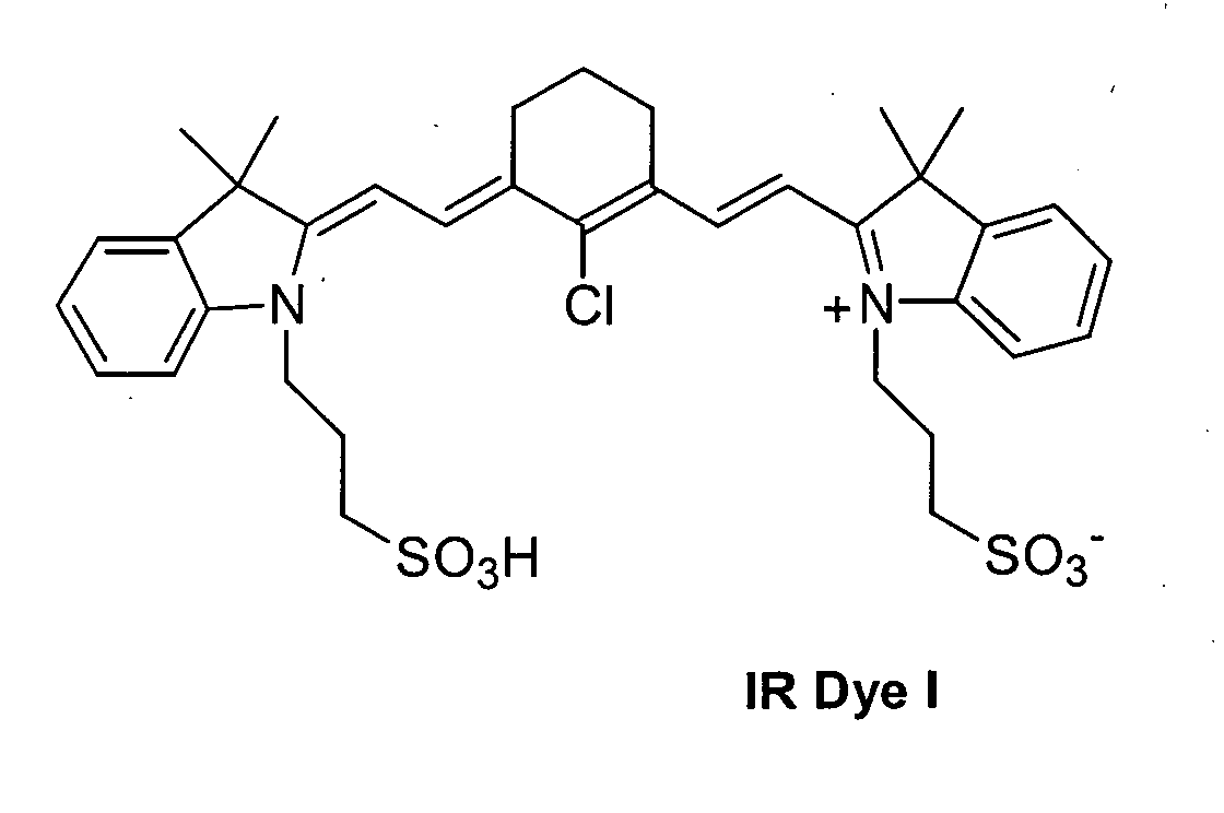
Coating solutions were prepared with the following composition: 2.8-2.9%
polymer; 0.01-0.03% ZONYL® FSN; 0.3-0.4% IR Dye infrared absorber; and
96-97% water.
Each coating solution was coated onto a grained and anodized aluminum
substrate using a #3 RK wire wound rod. The resulting imageable elements
were allowed to air dry. The dry imageable elements were imaged with a Creo
Trendsetter 3244 imagesetter (CREO, Burnaby, British Columbia, Canada) at an
exposure of 450 mJ/cm
2. The imaged imageable elements were placed on an
offset printing press with a commercial fountain solution and black ink. The non-image
areas were removed after several revolutions of the fountain and/or ink
rollers, and good prints were produced by the 25
th impression. The run length for
each of the resulting printing plates is shown in Table 2.
| Example | Polymer | Number of Impressions |
| 1 | P3 | 30,000 |
| 2 | P4 | 40,000 |
| 3 | P5 | 4,000 |
| 4 | P6 | 8,000 |
| 5 | P8 | 35,000 |
| 6 | P9 | 28,000 |
| 7 | P10 | 30,000 |
| 8 | P11 | 5,000 |
| 9 | P12 | 20,000 |
As shown by the results in Table 3, polymers with pendant urethane
groups did not provide adequate run length.
| Example | Polymer | Number of Impressions |
| C-1 | C1 | 50 |
| C-2 | C2 | 1,000 |
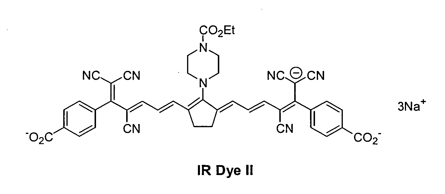
The procedure of Example 2 was repeated except that oxonol dyes IR
Dye II and IR Dye III were used in place of the cyanine IR Dye I. The resulting
imageable elements were imaged using the Creo Trendsetter 3244 imagesetter
at imaging energies of 300, 400, and 500 mJ/cm2. The resulting imaged
imageable elements were placed on a duplicator press for 250 impressions. The
resulting printing plates produced good prints for all exposures.
Examples 12-15
The procedure of Examples 1-9 was repeated using the polymers of
Examples 2 and 6 except CAB-O-JET® 200 and CAB-O-JET® 300 were used in
place of the IR Dye I infrared absorber. The resulting imageable elements were
imaged as in Example 1 at imaging energies of 300, 450, and 563 mJ/cm2. The
resulting imaged imageable elements were placed on a duplicator press for 250
impressions. All four the resulting printing plates produced good prints for all
exposures.
Examples 16-24
These examples illustrate imageable compositions that comprise a watersoluble
polymeric binder. The coating solutions that include a binder have the
following composition by weight percent: 2.8-2.9% polyurethane (dry weight);
0.3-0.6% binder (dry weight); 0.2-0.4% IR Dye I infrared absorber; 0.01-0.03%
surfactant; and 96-97% water. Each coating solution was coated onto a grained
and anodized aluminum substrate post treated with PVPA using a #3 RK wire
wound rod (R.K. Print-Coat Instruments, UK). The resulting imageable elements
were allowed to air dry.
Using the above formulation with polyurethane P4 and a variety of
polymeric binders, coating integrity was determined by applying and then
immediately removing a strip of cellophane tape. Each plate was then rated by
how much coating was removed by the tape, with 1=no coating removed, and
5=all coating removed. Results are shown in Table 4.
| Example | Binder | Coating Integrity |
| 2 | None | 4 |
| 16 | Polyvinylpyrrolidone-co-vinylacetate | 3 |
| 17 | Polyvinylpyrrolidone | 2 |
| 18 | Copolymer 845 | 2 |
| 19 | MOWIOL® 3-83 | 2 |
| 20 | Polyvinylimidazole | 1 |
| 21 | ALCOTEX® 864 | 2 |
| 22 | ALCOTEX® 975 | 2 |
| 23 | Polyacrylamide | 2 |
| 24 | Polyacrylic acid | 2 |
Using the same general formulation as in Examples 16-24, imageable
elements were prepared using various polyurethanes and polymeric binders.
The imageable elements were imaged as in Example 1 at an exposure of
300 mJ/cm
2. The imaged imageable elements were placed on an offset printing
press with a commercial fountain and black ink. The non-image area of the
plates was removed after several revolutions of the fountain and/or ink rollers,
and good prints were produced by the 25
th impression. The run length for each
plate is indicated below. Results are shown in Table 5.
| Example | Polyurethane | Binder | Run length |
| 19 | P4 | MOWIOL® 3-83 | 2,000 |
| 25 | P4 | AIRVOL® 203 | 5,000 |
| 26 | P4 | AIRVOL® 523 | 1,000 |
| 27 | P4 | MOWIOL® 4-98 | 12,000 |
| 28 | P7 | MOWIOL® 3-83 | 10,000 |
| 29 | P12 | MOWIOL® 3-83 | 5,000 |
| 30 | P13 | MOWIOL® 3-83 | >30,000 |
| 31 | P14 | MOWIOL® 3-83 | >30,000 |
| 32 | P15 | MOWIOL® 3-83 | 10,000 |
Imageable elements were prepared as in Examples 16-24 and imaged as
in Example 1 at an exposure energy of 300 mJ/cm
2. The compositions are given
in Table 6. The imaged imageable elements were placed on a duplicator press
for 250 impressions. Examples 33-40 below all resulted in good prints.
| Example | Polyurethane | Binder |
| 33 | P1 | S-LEC® K KW-1 |
| 34 | P1 | POVAL® C-506 |
| 35 | P2 | S-LEC@ K KW-1 |
| 36 | P2 | POVAL® C-506 |
| 37 | P4 | S-LEC® K KW-1 |
| 38 | P4 | S-LEC® K KW-3 |
| 39 | P14 | POVAL® C-506 |
| 40 | P 14 | POVAL® KL-506 |
This example illustrates processing and gumming of the imaged
imageable element before placing it on the press. The dry imageable element
was imaged at exposure energies of 300, 400, and 500 mJ/cm2. The imaged
imageable element was processed through only the rinse and gum sections of a
Kodak 85 N processor at 0.82 m/min (2.7 ft/min). The rinse section contained
water and the gum section contained Kodak Polychrome Graphics 850S plate
finisher. The non-imaged regions of the imaged imageable element were
partially removed when the element exited the processor. The resulting printing
plate was placed on a duplicator press for 250 impressions and produced good
prints at all three exposure energies.
Example 42
This example illustrates imaging of an imageable element of the invention
with a thermal head. The procedure of Example 6 was repeated except that the
substrate was an about 100 micron thick polyester sheet instead of aluminum.
The resulting imageable element was imaged with an OYO Instruments model
GS 618 Thermal Imagesetter (Oyo Instruments, Houston, TX, USA) and
produced a latent image as determined by bleaching of the infrared absorber and
the decreased water solubility of the imaged areas.
Having described the invention, we now claim the following and their
equivalents.


