EP1489786A1 - Data transmission device, repeater device, data transmission/reception device, and data communication method - Google Patents
Data transmission device, repeater device, data transmission/reception device, and data communication method Download PDFInfo
- Publication number
- EP1489786A1 EP1489786A1 EP03712862A EP03712862A EP1489786A1 EP 1489786 A1 EP1489786 A1 EP 1489786A1 EP 03712862 A EP03712862 A EP 03712862A EP 03712862 A EP03712862 A EP 03712862A EP 1489786 A1 EP1489786 A1 EP 1489786A1
- Authority
- EP
- European Patent Office
- Prior art keywords
- data
- networks
- level protocol
- network
- packet
- Prior art date
- Legal status (The legal status is an assumption and is not a legal conclusion. Google has not performed a legal analysis and makes no representation as to the accuracy of the status listed.)
- Withdrawn
Links
Images


Classifications
-
- H—ELECTRICITY
- H04—ELECTRIC COMMUNICATION TECHNIQUE
- H04L—TRANSMISSION OF DIGITAL INFORMATION, e.g. TELEGRAPHIC COMMUNICATION
- H04L1/00—Arrangements for detecting or preventing errors in the information received
- H04L1/0001—Systems modifying transmission characteristics according to link quality, e.g. power backoff
- H04L1/0006—Systems modifying transmission characteristics according to link quality, e.g. power backoff by adapting the transmission format
- H04L1/0007—Systems modifying transmission characteristics according to link quality, e.g. power backoff by adapting the transmission format by modifying the frame length
-
- H—ELECTRICITY
- H04—ELECTRIC COMMUNICATION TECHNIQUE
- H04L—TRANSMISSION OF DIGITAL INFORMATION, e.g. TELEGRAPHIC COMMUNICATION
- H04L47/00—Traffic control in data switching networks
- H04L47/10—Flow control; Congestion control
- H04L47/19—Flow control; Congestion control at layers above the network layer
-
- H—ELECTRICITY
- H04—ELECTRIC COMMUNICATION TECHNIQUE
- H04L—TRANSMISSION OF DIGITAL INFORMATION, e.g. TELEGRAPHIC COMMUNICATION
- H04L47/00—Traffic control in data switching networks
- H04L47/10—Flow control; Congestion control
- H04L47/26—Flow control; Congestion control using explicit feedback to the source, e.g. choke packets
-
- H—ELECTRICITY
- H04—ELECTRIC COMMUNICATION TECHNIQUE
- H04L—TRANSMISSION OF DIGITAL INFORMATION, e.g. TELEGRAPHIC COMMUNICATION
- H04L47/00—Traffic control in data switching networks
- H04L47/10—Flow control; Congestion control
- H04L47/36—Flow control; Congestion control by determining packet size, e.g. maximum transfer unit [MTU]
-
- H—ELECTRICITY
- H04—ELECTRIC COMMUNICATION TECHNIQUE
- H04W—WIRELESS COMMUNICATION NETWORKS
- H04W28/00—Network traffic management; Network resource management
- H04W28/02—Traffic management, e.g. flow control or congestion control
-
- H—ELECTRICITY
- H04—ELECTRIC COMMUNICATION TECHNIQUE
- H04W—WIRELESS COMMUNICATION NETWORKS
- H04W8/00—Network data management
- H04W8/02—Processing of mobility data, e.g. registration information at HLR [Home Location Register] or VLR [Visitor Location Register]; Transfer of mobility data, e.g. between HLR, VLR or external networks
- H04W8/04—Registration at HLR or HSS [Home Subscriber Server]
-
- H—ELECTRICITY
- H04—ELECTRIC COMMUNICATION TECHNIQUE
- H04L—TRANSMISSION OF DIGITAL INFORMATION, e.g. TELEGRAPHIC COMMUNICATION
- H04L47/00—Traffic control in data switching networks
- H04L47/10—Flow control; Congestion control
- H04L47/43—Assembling or disassembling of packets, e.g. segmentation and reassembly [SAR]
-
- H—ELECTRICITY
- H04—ELECTRIC COMMUNICATION TECHNIQUE
- H04W—WIRELESS COMMUNICATION NETWORKS
- H04W28/00—Network traffic management; Network resource management
- H04W28/02—Traffic management, e.g. flow control or congestion control
- H04W28/06—Optimizing the usage of the radio link, e.g. header compression, information sizing, discarding information
Definitions
- the present invention relates to a data transmitter, gateway, data transceiver and data communication method capable of providing communication adaptable to error conditions varying during data communication between transceivers via networks whose error conditions are variable.
- Fig. 1 shows a conventional data transceiver system disclosed in Japanese patent application laid-open No. 11-331234.
- a radio terminal unit conducts data transmission and reception to and from an application server as follows.
- the radio terminal unit or base station notifies a gateway server of circuit conditions in a radio section, and the gateway server adjusts parameters such as packet length and retransmission duration when converting to a radio protocol, thereby carrying out the data communication.
- the conventional data communication system disclosed in Japanese patent application laid-open No. 11-331234 transmits data after the gateway converts into the radio network protocol using parameters (packet length, retransmission timer, and window size) suitable for the circuit conditions of the radio network.
- level protocols In an ordinary video and audio multimedia communication, however, there are different level protocols: a lower level protocol different on the radio and the Internet sections; and a higher level protocol common to the radio and the Internet sections for enabling streaming communication.
- the foregoing conventional data communication system enables transmission and reception according to the parameters matching to the error characteristics of the networks according to only the lower level protocols, thereby being unable to conduct the transmission at an appropriate packet length according to the higher level protocol.
- the present invention is implemented to solve the foregoing problem. Therefore it is an object of the present invention to provide a data transmitter, gateway, data transceiver and data communication method capable of reducing the fraction of packets lost by receiving data at a packet length adaptable to the error conditions of the networks even according to the common higher level protocol.
- a data transmitter for carrying out data communication with a data receiver via a plurality of networks with different characteristics using a higher level protocol common to the plurality of networks and a lower level protocol inherent in each of the plurality of networks, wherein the data transmitter receives error occurrence conditions in the networks from the data receiver, and variably controls a packet length of the higher level protocol common to the plurality of networks in response to the error occurrence conditions in the networks.
- the data transmitter can vary the packet length not only of the lower level protocol, but also of the protocol common to the networks in response to the conditions of the networks.
- it can carry out communication efficiently in the network with a small number of errors, and effectively in the network with a large number of errors with preventing the adverse effect of the errors as much as possible.
- the data transmitter may be characterized in that when it variably controls the packet length of the higher level protocol common to the plurality of networks in response to the error occurrence conditions in the networks, it variably adjusts the packet length of the higher level protocol in accordance with to a structure and characteristics of data to be transmitted.
- a gateway for repeating data communication between a data transmitter and a data receiver via a plurality of networks with different characteristics using a higher level protocol common to the plurality of networks and a lower level protocol inherent in each of the plurality of networks, wherein the gateway receives error occurrence conditions in the networks from the data receiver, and variably controls a packet length of the higher level protocol common to the plurality of networks in response to the error occurrence conditions in the networks.
- the gateway can vary the packet length not only of the lower level protocol, but also of the protocol common to the networks in response to the conditions of the networks.
- it can carry out communication efficiently in the network with a small number of errors, and effectively in the network with a large number of errors with preventing the adverse effect of the errors as much as possible.
- the gateway may be characterized in that it variably controls the packet length of the lower level protocol different in each network to a packet length adaptable to the error conditions of each network.
- the gateway may be characterized in that the error occurrence conditions in the networks received from the data receiver include error occurrence conditions in the networks transmitted from another gateway at an interface with another network.
- a data transceiver for carrying out data communication with another data transceiver via a plurality of networks with different characteristics using a higher level protocol common to the plurality of networks and a lower level protocol inherent in each of the plurality of networks, wherein the data transceiver extracts error occurrence conditions in the networks when receiving data from the another data transceiver, and variably controls a packet length of the higher level protocol common to the plurality of networks in response to the error occurrence conditions in the networks extracted.
- the data transceiver can vary the packet length not only of the lower level protocol, but also of the protocol common to the networks in response to the conditions of the networks.
- it can carry out communication efficiently in the network with a small number of errors, and effectively in the network with a large number of errors with preventing the adverse effect of the errors as much as possible.
- a data communication method of carrying out data communication between a data transmitter and a data receiver via a plurality of networks with different characteristics using a higher level protocol common to the plurality of networks and a lower level protocol inherent in each of the plurality of networks wherein the data communication method variably controls a packet length of the higher level protocol common to the plurality of networks in response to error occurrence conditions in the networks.
- the data communication method variably controls a packet length of the higher level protocol common to the plurality of networks in response to error occurrence conditions in the networks.
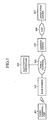
- Fig. 2 is a schematic diagram showing a basic configuration of a data transceiver system of an embodiment 1 in accordance with the present invention, which carries out the data transmission and reception via two networks with different characteristics.
- the reference numeral 201 designates a data receiver (shortened to "receiver” in the drawing); 202 designates a data transmitter (shortened to "transmitter” in the drawing); 203 designates a gateway; 204 designates a network 1; 205 designates a network 2; 206 designates transmission data; 207 designates a protocol stack for transmitting the transmission data 206 via the network 1; 208 designates a protocol stack for transmitting the transmission data 206 via the network 2; and 209 designates received data.
- the data receiver 201 receives the transmission data 206 from the data transmitter 202 via the network 1 (204) and network 2 (205) with different characteristics.
- the network 1 and network 2 have an error rate varying depending on time or a state and position of the data receiver 201.
- the total error rate of the network 1 (204) and network 2 (205) for the data receiver 201 at time ti is represented by ER(ti).
- the transmission data 206 is transmitted between the data transmitter 202 and data receiver 201 using a protocol common to the networks, which is described in the protocol stacks 208 and 207 as the higher level protocol.
- the transmission data 206 is transmitted through the network 1 using a network 1 protocol described in the protocol stack 207 as the lower level protocol, and through the network 2 using a network 2 protocol described in the protocol stack 208 as the lower level protocol.
- the conversion of the lower level protocols between the network 1 and network 2 is carried out by the gateway 203 serving as a gateway.
- Fig. 3 illustrates network protocol stacks for communication using the RTP (Real-time Transport Protocol) /UDP/IP as an example of the communication protocol.
- the reference numeral 1501 designates a protocol stack for carrying out communication via the network 1
- 1504 designates aprotocol stack for carrying out communication via the network 2.
- the reference 1502 designates a higher level protocol common to the network 1 and network 2
- 1503 designates a lower level network protocol for the network
- 1505 designates a lower level network protocol for the network 2.
- the gateway 203 carries out the protocol conversion between the lower level network protocol 1503 and lower level network protocol 1505 of the networks 1 and 2.
- Fig. 4 is a block diagram showing a detailed configuration of the data transmitter 202 of the embodiment 1 as shown in Fig. 2.
- the reference numeral 301 designates a packet transmitting section
- 302 designates a higher level protocol packet generating section
- 303 designates a lower level protocol packet generating section
- 304 designates a packet sending section
- 305 designates a higher level protocol packet length deciding section
- 307 designates network error conditions
- 309 designates an error check section
- 206 designates the transmission data
- 202 designates the transmitter
- 205 designates the network 2.
- the higher level protocol packet generating section 302 in the data transmitter 202 generates a packet with the higher level protocol for transmitting the transmission data 206.
- the higher level protocol packet length deciding section 305 decides it at a packet length adaptable to the error conditions with reference to the data about the network error conditions 307.
- the packet of the higher level protocol generated is supplied to the lower level protocol packet generating section 303.
- the packet generated by the lower level protocol packet generating section 303 is supplied to the packet sending section 304 to be transferred to the network 2 (205).
- the error check section 309 collects the error information transmitted from the data receiver 201, and stores in the network error conditions 307.
- Fig. 5 is a diagram illustrating a data structure of the network error conditions.
- the reference numeral 1201 designates an example of data representing network conditions.
- the network error conditions are represented, for example, by the data about time and fraction of packets lost calculated and stored at each time.
- the fraction n of packets lost represents the ratio of the number of packets lost from time n-1 to time n to the total number of the packets transmitted during that time period.
- Fig. 6 shows a detailed configuration of the higher level protocol packet length deciding section 305 as shown in Fig. 4.
- the reference numeral 1401 designates a packet length deciding section
- 1402 designates a packet length deciding data
- 305 designates the higher level protocol packet length deciding section
- 307 designates the network error conditions
- 302 designates the higher level protocol packet generating section.
- the packet length deciding section 1401 in the higher level protocol packet length deciding section 305 reads the network error conditions 307, and decides the packet length to be transmitted. To decide the packet length, the packet length deciding section 1401 reads the packet length deciding data 1402, and retrieves the packet length corresponding to the error conditions of the network.
- the packet length deciding data 1402 consists of a table having columns representing ranges of network error rates and packet lengths, which enables the packet length deciding section 1401 to search for the range including the current network error rate, and to retrieve the packet length.
- Fig. 7 is a block diagram showing a detailed configuration of the data receiver 201 as shown in Fig. 2.
- the reference numeral 401 designates a packet input section
- 402 designates a lower level protocol packet disassembling section
- 403 designates a higher level protocol packet disassembling section
- 209 designates the received data
- 405 designates the error condition notifying section.
- the operation of the data receiver 201 as shown in Fig. 7 will be described.
- the packet supplied from the network 1 (204) to the packet input section 401 is restored to the data through the lower level protocol packet disassembling section 402 that disassembles the lower level protocol, and the higher level protocol packet disassembling section 403 that disassembles the higher level protocol.
- the data is stored in the received data 209.
- the error condition notifying section 405 analyzes the reception condition of the packet at the higher level protocol packet disassembling section 403 to obtain the fraction of packets lost.
- the error condition notifying section 405 transmits the error conditions to the data transmitter 202.
- Fig. 8 illustrates a packet format 901 of the RTP (Real-time Transport Protocol) as an example of the higher level protocol.
- the error condition notifying section 405 obtains the fraction lost of incoming packets to the data receiver 201 from the consecution of the "sequence number" in the RTP packet format.
- V designates a version
- P designates a padding flag
- X designates an extension flag
- CC designates a contributing source (CSRC) count
- M designates a marker bit
- PT designates a payload type.
- Fig. 9 illustrates a packet format 801 of an RTCP (RTP Control Protocol) as an example of the protocol used for the error condition communication.
- RTCP RTP Control Protocol
- V designates a version
- P designates a padding flag
- PT designates a payload type.
- the error condition notifying section 405 writes information into the "fraction of packets lost" and "cumulative number of packets lost" fields of the RTCP packet format, and transmits them to the transmitter.
- the error condition notifying section 405 of the data receiver 201 transmits reception error conditions to the data transmitter 202 by the RTCP packet as illustrated in Fig. 9.
- Fig. 10 is a flowchart illustrating the procedure of generating the error condition data in the data receiver 201 of the present embodiment 1.
- the higher level protocol packet disassembling section 403 receives a packet (step ST1), an RTP packet, for example, the higher level protocol packet disassembling section 403 extracts the sequence number of the packet received (see, Fig. 8). Then, it computes the number of packets lost by comparing the sequence number with the sequence number of the packet previously received (step ST2). It notifies the error condition notifying section 405 of the number of packets lost and the number of packets received (step ST3).
- step ST5 it disassembles the packet, extracts and stores the received data (step ST4), and enters a reception standby mode of the next packet (step ST5).
- Receiving the next packet (“YES" at step ST5) , it returns the processing to the foregoing step ST1.
- the error condition notifying section 405 receives the notification of the number of packets lost and the number of packets received from the higher level protocol packet disassembling section 403 through the processing at step ST3 ("YES" at step ST11), the error condition notifying section 405 counts up the number of packets lost and the number of packets received (step ST12). When the timing of transmitting the error condition comes (“YES” at step ST13), the error condition notifying section 405 computes, when using the RTCP packet, for example, the fraction of packets lost and the cumulative number of packets lost, sends them to the data transmitter 202 as the error condition data (step ST14), and initializes the number of packets lost and the number of packets received (step ST15) .
- the present embodiment 1 is configured such that the data receiver 201 or gateway 203 notifies the data transmitter 202 of the error conditions at the data receiver 201 or gateway 203 via the networks 1 (204) and 2 (205), and that in response to the error conditions, the data transmitter 202 carries out the transmission/reception with the packet length adaptable to the error rate even for the higher level protocol common to the networks 1 (204) and 2 (205). Therefore, the present embodiment 1 can reduce the fraction of packets lost even for the higher level protocol common to the networks 1 (204) and 2 (205).
- the network 1 is a radio network such as a mobile telephone network
- the network 2 is a wired network such as the Internet
- the lower level protocols differ in the radio protocol and wired protocol
- the higher level uses the RTP/UDP/IP as the common protocol
- the error conditions between the data receiver 201 and the data transmitter 202 are transmitted according to the RTCP/UDP/IP.
- the lower level protocol inherent in the radio network is used to send a short packet suitable for the radio network with a greater number of errors
- the lower level protocol inherent to the wired network is used to send the packet length of the higher level protocol to transmit/receive the data efficiently.
- the receiver If the radio conditions of the receiver are degraded and the error rate of the network increases, the receiver notifies the transmitter of the phenomenon using the RTCP. Receiving the error conditions, the transmitter side sends the RTP higher level packet with reducing the packet length.
- the present embodiment 1 can reduce the adverse effect of the lower level protocol packet loss in the radio network on the higher level protocol (RTP), thereby enabling the transmission/reception of the data adaptable to the error conditions of the networks.
- the present embodiment 2 handles a system that decides the packet length by using the error conditions of the networks 1 and 2 independently.
- Fig. 11 is a schematic diagram showing a basic configuration of the data transceiver system of an embodiment 2 in accordance with the present invention, which carries out the data transmission/reception via the two networks with different characteristics.
- the reference numeral 501 designates a data receiver (shortened to "receiver” in the drawing)
- 502 designates a data transmitter (shortened to "transmitter” in the drawing)
- 503 designates a gateway
- 204 designates the network 1
- 205 designates the network 2
- 206 designates the transmission data
- 507 designates a protocol stack in the network 1
- 508 designates a protocol stack in the network 2
- 209 designates the received data.
- the data receiver 501 receives the received data 206 from the data transmitter 502 via the network 1 (204) and network 2 (205) with different characteristics.
- the network 1 and network 2 have an error rate varying depending on time or a state and position of the data receiver 501.
- the error rates in the network 1 (204) and network 2 (205) for the data receiver 501 at time ti are represented by ER1(ti) and ER2(ti), respectively.
- the transmission data 206 is transferred between the data transmitter 502 and the data receiver 501 using the protocol common to the networks described in the protocol stacks 507 and 508 as the higher level protocol, and is transferred in the network 1 using the network 1 protocol described in the protocol stack 507 as the lower level protocol, and in the network 2 using the network 2 protocol described in the protocol stack 508 as the lower level protocol.
- the gateway 503 carries out.
- Fig. 12 is a block diagram showing a detailed configuration of the data transmitter 502 of the embodiment 2 as shown in Fig. 11.
- the reference numeral 302 designates the higher level protocol packet generating section
- 602 designates a lower level protocol packet generating section
- 304 designates the packet sending section
- 305 designates the higher level protocol packet length deciding section
- 605 designates a lower level protocol packet length deciding section
- 309 designates the error check section
- 607 designates network 2 error conditions
- 206 designates the transmission data.
- the higher level protocol packet generating section 302 generates a packet of the higher level protocol to transmit the transmission data 206.
- the higher level protocol packet length deciding section 305 decides it at a packet length adaptable to the error conditions with reference to the data about the network 2 error conditions 607.
- the packet of the higher level protocol generated is supplied to the lower level protocol packet generating section 602.
- the lower level protocol packet length deciding section 605 decides it at a packet length adaptable to the error conditions with reference to the data about the network 2 error conditions 607.
- the configurations of the higher level and lower level protocol packet length deciding sections are the same as the configuration of the higher level protocol packet length deciding section 305 as shown in Fig. 6.
- the packet generated by the lower level protocol packet generating section 602 is supplied to the packet sending section 304 to be transferred to the network 2 (205).
- the error check section 309 collects the error conditions of the network 2, and stores in the network 2 error conditions 607.
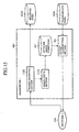
- Fig. 13 is a block diagram showing a detailed configuration of the gateway 503 of the embodiment 2 as shown in Fig. 11.
- the reference numeral 701 designates a packet receiving section
- 702 designates a lower level protocol packet disassembling section
- 703 designates a higher level protocol packet disassembling section
- 704 designates a higher level protocol packet generating section
- 705 designates a lower level protocol packet generating section
- 706 designates a packet sending section
- 707 designates a higher level protocol packet length deciding section
- 708 designates a lower level protocol packet length deciding section
- 709 designates an error condition notifying section
- 710 designates an error check section
- 711 designates network 1 error conditions
- 712 designates a packet repeating section
- 503 designates the gateway
- 204 designates the network 1 error conditions
- 712 designates a packet repeating section
- 503 designates the gateway
- 204 designates the network 1 error conditions
- 712 designates a packet repeating section
- the packet receiving section 701 captures from the network 2 (205) the packet received from the data transmitter 502, and supplies it to the lower level protocol packet disassembling section 702.
- the lower level protocol packet disassembling section 702 disassembles the lower level protocol of the packet, and supplies the packet to the higher level protocol packet disassembling section 703.
- the higher level protocol disassembling section 703 disassembles the higher level protocol, and temporarily stores the data into the buffer 716 consisting of a FIFO.
- the higher level protocol packet generating section 704 reads the transmission data from the buffer 716, generates the higher level protocol packet, and supplies it to the lower level protocol packet generating section 705.
- the higher level protocol packet length deciding section 707 decides it with reference to the network 1 error conditions 711.
- the lower level protocol packet generating section 705 generates a lower level protocol packet for the network 1 from the higher level protocol packet supplied from the higher level protocol packet generating section 704.
- the lower level protocol packet length deciding section (708) decides it with reference to the network 1 error conditions 711.
- the configurations of the higher level and lower level protocol packet length deciding sections 707 and 708 are assumed to be the same as the configuration of the higher level protocol packet length deciding section 305 as shown in Fig. 6.
- the RTP packet as illustrated in Fig. 8 is used as the common higher level protocol, and the packet length is changed at the gateway (503), it is necessary to reassign the sequence number. Assume that even if there is a packet lost in the network 2, the RTP packets tobe generated anew are sequentially numbered with excluding the portions lost.
- the packet generated by the lower level protocol packet generating section 705 is supplied to the packet sending section 706 to be sent out to the network 1 (204). Then, the data receiver 501 of the present embodiment 2 as shown in Fig. 11 receives the data via the network 1 (204).
- the data receiver 501 has the same configuration and operates in the same manner as the data receiver 201 of the foregoing embodiment 1 as shown in Fig. 7. Thus, the error condition notifying section 405 notifies the gateway 503 of the error conditions.
- the notification of the error conditions is transmitted from the data receiver 501 to the gateway 503.
- the gateway 503 merges the error conditions at the data receiver 501 due to the network 1 (204) with the error conditions at the gateway 503 due to the network 2 (205), and supplies the resultant error conditions to the data transmitter 502.
- the error check section 710 receives the error condition information between the gateway 503 and the data receiver 501 in the network 1, and stores it as the network 1 error conditions 711.
- the error condition notifying section 709 of the gateway 503 captures the fraction of packets lost and the number of packets lost obtained as a result of the analysis by the higher level protocol packet disassembling section 703 as well as the error condition information in the network 1 from the network 1 error conditions 711, and transmits these error conditions to the data transmitter 502 via the network 2 (205).
- the reception error conditions of the receiver indicates the error condition of the network 1
- the reception error conditions of the gateway indicates the error condition of the network 2.
- the present embodiment 2 is configured such that the gateway 503 detects the error conditions of the networks 1 and 2, and controls the packet lengths of the common higher level protocol and lower level protocol when transmitting data from the gateway 503 to the data receiver 501, and that the gateway 503 transmits the error conditions to the data transmitter 502 so that the data transmitter 502 controls the packet lengths of the common higher level protocol and lower level protocol when transmitting data to the gateway 503.
- the packet with the length adaptable to the error conditions of the network 1 is transmitted through the network 1 for both the common higher level protocol and lower level protocol.
- the packet with the length adaptable to the error conditions not only of the network 2, but also of the network 1 is transmitted through the network 2 for both the common higher level protocol and lower level protocol.
- the lower level protocols differ in the radio protocol and wired protocol
- the higher level uses the RTP/UDP/IP as the common protocol
- the error conditions between the data receiver 501 and the data transmitter 502 are transmitted according to the RTCP/UDP/IP.
- the packet length is still more variable in accordance with the error conditions of the network 1.
- the packet length of the higher level protocol is also variable in accordance with the error conditions of the network 2.
- the gateway 503 converts the RTP packet length based on the common protocol according to the error conditions of the network 1 and network 2 so that the network 2 can use a long packet to carry out efficient transmission because of a smaller number of errors, and the network 1 can use a short packet to reduce the adverse effect of the error because of a greater number of errors.
- the present invention is not limited to such a configuration.
- the data transmitter 502 transmits data to the data receiver 501 through a plurality of gateway.
- the packet repeating section of each gateway generates the error condition data about the network to be repeated, and transmits it to the party gateway, thereby enabling the transmission/reception with the packet length corresponding to the error conditions.
- the data receiver and gateway each have a means for notifying their own network error conditions.
- the present embodiment 3 handles a system capable of capturing the error conditions without such a means for notifying the error conditions of the network.
- Fig. 14 is a schematic diagram showing a basic configuration of a data transceiver system of an embodiment 3 in accordance with the present invention.
- the reference numeral 1001 designates a transceiver 1
- 1002 designates a transceiver 2
- 1003 designates a gateway
- 204 designates the network 1
- 205 designates the network 2
- 1006 designates transmission data 1
- 1007 designates transmission data 2
- 1008 designates a protocol stack of the network
- 1009 designates a protocol stack of the network
- 1010 designates received data
- 1011 designates received data 2.
- ER(ti) is the total error rate of the network 1 (204) and network 2 (205) for the transceiver 1 (1001) at time ti.
- the transceiver 1 (1001) transmits the transmission data 1 (1006) to the transceiver 2 (1002), and receives the received data 1 (1010) from the transceiver 2 (1002).
- the transceiver 2 (1002) transmits the transmission data 2 (1007) to the transceiver 1 (1001), and receives the received data 2 (1011) from the transceiver 1 (1001).
- Fig. 15 is a block diagram showing a detailed configuration of the transceiver 1 (or 2) of the embodiment 3 as shown in Fig. 14.
- the reference numeral 301 designates a packet transmitting section similar to the packet transmitting section 609 of the data transmitter 502 of the embodiment 2 as shown in Fig. 12;
- 1102 designates a packet receiving section similar to the packet receiving section 404 of the data receiver 201 of the embodiment 1 as shown in Fig. 7; 1103 designates an error check section; 307 designates the network error conditions; 1010 designates received data; 1006 designates transmission data; 1001 designates the transceiver; and 204 designates the network 1.
- the operation of the transceiver 1 (or 2) of the embodiment 3 as shown in Fig. 15 will be described.
- the transceiver 1 (1001) performs bidirectional data communication with the party transceiver 2 (1002).
- the network routes of the transmission/reception are assumed to use the same network.
- the network 1 (204) and network 2 (205) are used.
- the transceiver 1 (1001) its packet receiving section (1102), receiving and disassembling a packet, extracts the loss conditions of a packet in the same manner as the packet receiving section 404 of the data receiver 201 of the embodiment 1 as shown in Fig. 7, and supplies the loss conditions to the error check section 1103 .
- the error check section 1103 generates the network error condition data from the packet loss conditions received, and stores the data in the network error conditions 307.
- the packet transmitting section 301 decides the packet length of the higher level protocol and that of the lower level protocol with reference to the network error conditions 307 in the same manner as the packet transmitting section 609 of the data transmitter 502 in the embodiment 2 as shown in Fig. 12, and transmits the packet.
- the present embodiment 3 is configured such that the transceiver (1001) or (1002), when transmitting data, decides the packet length of the higher level protocol and that of the lower level protocol with reference to the network error conditions 307 in the same manner as the packet transmitting section 609 of the data transmitter 502 in the foregoing embodiment 2 as shown in Fig. 12, and transmits the packet, and when receiving the data, extracts the loss conditions of the packet when receiving and disassembling the packet in the same manner as the packet receiving section 404 of the data receiver 201 of the foregoing embodiment 1 as shown in Fig. 7, and that the error check section 1103 generates the network error condition data from the packet loss conditions received, and stores the data in the network error conditions 301.
- the transceiver (1001) or (1002) when transmitting data, decides the packet length of the higher level protocol and that of the lower level protocol with reference to the network error conditions 307 in the same manner as the packet transmitting section 609 of the data transmitter 502 in the foregoing embodiment 2 as shown in Fig. 12, and transmit
- the foregoing embodiments 1-3 each decide the appropriate packet length with reference to the error conditions of the networks.
- the present embodiment 4 decides the packet length when transmitting media data such as video or audio information that imposes conditions on dividing a packet.
- Fig. 16 is a block diagram showing a detailed configuration of the data transmitter 502 of the present embodiment 4.
- the data transmitter 502 of the present embodiment 4 is characterized by adding packet division conditions 1311 to the data transmitter 202 of the embodiment 1 as shown in Fig. 4.
- the reference numeral 302 designates the higher level protocol packet generating section
- 303 designates the lower level protocol packet generating section
- 304 designates the packet sending section
- 1304 designates a higher level protocol packet length deciding section
- 309 designates the error check section
- 307 designates the network 2 error conditions
- 206 designates the transmission data
- 1309 designates a packet transmitting section
- 205 designates the network 2.
- the reference numeral 1311 designates the packet division conditions.
- the higher level protocol packet length deciding section 1304 refers to the packet division conditions 1311 to decide the packet length to be transmitted.
- the packet division conditions include the structure and characteristic information of the data transmitted, and offers the reference to decide the length of the packet.
- Fig. 17 illustrates an example that transmits MPEG-4 video data according to the RTP in the present embodiment 4.
- reference numerals 1601-1606 represent an MPEG-4 video data structure: 1601 and 1602 each designate a VOP (Video Obj ect Plane) representing a video frame.
- the VOP can be composed of a plurality of video packets, which are designated by the reference numerals 1603-1606. It is preferable that the MPEG-4 video data with such a structure be packetized on a VOP by VOP basis or VP by VP basis.
- the packet division conditions 1311 specify the packet division conditions on the VOP or VP (video packet) basis. In this way, the packet length can be divided into a length more suitable for the error conditions under the control of the packet division conditions 1311.
- reference numerals 1607-1610 each designate a packet structure: 1607 and 1608 represent the case of structuring the packet on a VOP by VOP basis under the control of the packet division conditions 1311; and 1609 and 1610 represent the case of structuring the packet on a VP by VP basis under the control of the packet division conditions 1311.
- the present embodiment 4 is configured such that it includes the packet division conditions 1311 that store the information on the structure and characteristics of the data in advance, and that when the higher level protocol packet length deciding section 1304 decides the packet length, it refers to the packet division conditions 1311 and decides the higher level protocol packet length.
- the present embodiment can vary the packet length in accordance with the characteristics and structure of the data to be transmitted.
- the present embodiment 4 is described by way of example including the packet division conditions 1311 added to the data transmitter 202 of the embodiment 1 shown in Fig. 4, the present invention is not limited to the configuration.
- the packet division conditions 1311 can be added to the data transmitter 502 of the embodiment 2 shown in Fig. 12 so that the higher level protocol packet length deciding section 305 refers to the packet division conditions 1311 to decide the higher level protocol packet length; that the packet division conditions 1311 can be added to the gateway 503 of the embodiment 2 as shown in Fig.
- the higher level protocol packet length deciding section 707 refers to them when it decides the higher level protocol packet length of the packet to be transmitted to the network 1 (204); or that the packet division conditions 1311 can be added to the transceiver 1001 of the embodiment 3 shown in Fig. 15 so that the higher level protocol packet length deciding section refers to them when it decides the higher level protocol packet length.
- the data transmitter in accordance with the present invention can achieve the data communication adaptable to the changes in the error conditions.
Landscapes
- Engineering & Computer Science (AREA)
- Computer Networks & Wireless Communication (AREA)
- Signal Processing (AREA)
- Quality & Reliability (AREA)
- Databases & Information Systems (AREA)
- Data Exchanges In Wide-Area Networks (AREA)
- Communication Control (AREA)
- Detection And Prevention Of Errors In Transmission (AREA)
Abstract
A data receiver (201) or gateway (203) notifies a data
transmitter (202) of error conditions in the data receiver (201)
or gateway (203) via networks 1 (204) and 2 (205). According
to the error conditions, the data transmitter (202) transmits
data at a packet length corresponding to the error rate even
for the higher level protocol common the networks 1 (204) and
2 (205) , as well. Thus, the fraction of packets lost can be reduced
in the higher level protocol common to the networks 1 (204) and
2 (205).
Description
The present invention relates to a data transmitter, gateway,
data transceiver and data communication method capable of
providing communication adaptable to error conditions varying
during data communication between transceivers via networks whose
error conditions are variable.
Fig. 1 shows a conventional data transceiver system
disclosed in Japanese patent application laid-open No. 11-331234.
In the data transceiver system, a radio terminal unit conducts
data transmission and reception to and from an application server
as follows. The radio terminal unit or base station notifies
a gateway server of circuit conditions in a radio section, and
the gateway server adjusts parameters such as packet length and
retransmission duration when converting to a radio protocol,
thereby carrying out the data communication.
The conventional data communication system disclosed in
Japanese patent application laid-open No. 11-331234 transmits
data after the gateway converts into the radio network protocol
using parameters (packet length, retransmission timer, and window
size) suitable for the circuit conditions of the radio network.
In an ordinary video and audio multimedia communication,
however, there are different level protocols: a lower level
protocol different on the radio and the Internet sections; and
a higher level protocol common to the radio and the Internet
sections for enabling streaming communication. The foregoing
conventional data communication system enables transmission and
reception according to the parameters matching to the error
characteristics of the networks according to only the lower level
protocols, thereby being unable to conduct the transmission at
an appropriate packet length according to the higher level
protocol.
The present invention is implemented to solve the foregoing
problem. Therefore it is an object of the present invention to
provide a data transmitter, gateway, data transceiver and data
communication method capable of reducing the fraction of packets
lost by receiving data at a packet length adaptable to the error
conditions of the networks even according to the common higher
level protocol.
According to a first aspect of the present invention, there
is provided a data transmitter for carrying out data communication
with a data receiver via a plurality of networks with different
characteristics using a higher level protocol common to the
plurality of networks and a lower level protocol inherent in
each of the plurality of networks, wherein the data transmitter
receives error occurrence conditions in the networks from the
data receiver, and variably controls a packet length of the higher
level protocol common to the plurality of networks in response
to the error occurrence conditions in the networks. Thus, it
can vary the packet length not only of the lower level protocol,
but also of the protocol common to the networks in response to
the conditions of the networks. As a result, it can carry out
communication efficiently in the network with a small number
of errors, and effectively in the network with a large number
of errors with preventing the adverse effect of the errors as
much as possible.
The data transmitter may be characterized in that when it
variably controls the packet length of the higher level protocol
common to the plurality of networks in response to the error
occurrence conditions in the networks, it variably adjusts the
packet length of the higher level protocol in accordance with
to a structure and characteristics of data to be transmitted.
According to a second aspect of the present invention, there
is provided a gateway for repeating data communication between
a data transmitter and a data receiver via a plurality of networks
with different characteristics using a higher level protocol
common to the plurality of networks and a lower level protocol
inherent in each of the plurality of networks, wherein the gateway
receives error occurrence conditions in the networks from the
data receiver, and variably controls a packet length of the higher
level protocol common to the plurality of networks in response
to the error occurrence conditions in the networks. Thus, it
can vary the packet length not only of the lower level protocol,
but also of the protocol common to the networks in response to
the conditions of the networks. As a result, it can carry out
communication efficiently in the network with a small number
of errors, and effectively in the network with a large number
of errors with preventing the adverse effect of the errors as
much as possible.
The gateway may be characterized in that it variably controls
the packet length of the lower level protocol different in each
network to a packet length adaptable to the error conditions
of each network.
The gateway may be characterized in that the error occurrence
conditions in the networks received from the data receiver include
error occurrence conditions in the networks transmitted from
another gateway at an interface with another network.
According to a third aspect of the present invention, there
is provided a data transceiver for carrying out data communication
with another data transceiver via a plurality of networks with
different characteristics using a higher level protocol common
to the plurality of networks and a lower level protocol inherent
in each of the plurality of networks, wherein the data transceiver
extracts error occurrence conditions in the networks when
receiving data from the another data transceiver, and variably
controls a packet length of the higher level protocol common
to the plurality of networks in response to the error occurrence
conditions in the networks extracted. Thus, it can vary the packet
length not only of the lower level protocol, but also of the
protocol common to the networks in response to the conditions
of the networks. As a result, it can carry out communication
efficiently in the network with a small number of errors, and
effectively in the network with a large number of errors with
preventing the adverse effect of the errors as much as possible.
According to a fourth aspect of the present invention, there
is provided a data communication method of carrying out data
communication between a data transmitter and a data receiver
via a plurality of networks with different characteristics using
a higher level protocol common to the plurality of networks and
a lower level protocol inherent in each of the plurality of networks,
wherein the data communication method variably controls a packet
length of the higher level protocol common to the plurality of
networks in response to error occurrence conditions in the
networks. Thus, it can vary the packet length not only of the
lower level protocol, but also of the protocol common to the
networks in response to the conditions of the networks. As a
result, it can carry out communication efficiently in the network
with a small number of errors, and effectively in the network
with a large number of errors with preventing the adverse effect
of the errors as much as possible.
The best mode for carrying out the invention will now be
described with reference to the accompanying drawings to explain
the present invention in more detail.
Fig. 2 is a schematic diagram showing a basic configuration
of a data transceiver system of an embodiment 1 in accordance
with the present invention, which carries out the data
transmission and reception via two networks with different
characteristics. In Fig. 2, the reference numeral 201 designates
a data receiver (shortened to "receiver" in the drawing); 202
designates a data transmitter (shortened to "transmitter" in
the drawing); 203 designates a gateway; 204 designates a network
1; 205 designates a network 2; 206 designates transmission data;
207 designates a protocol stack for transmitting the transmission
data 206 via the network 1; 208 designates a protocol stack for
transmitting the transmission data 206 via the network 2; and
209 designates received data.
The operation of the data transceiver system as shown in
Fig. 2 will be described. The data receiver 201 receives the
transmission data 206 from the data transmitter 202 via the network
1 (204) and network 2 (205) with different characteristics. The
network 1 and network 2 have an error rate varying depending
on time or a state and position of the data receiver 201. The
total error rate of the network 1 (204) and network 2 (205) for
the data receiver 201 at time ti is represented by ER(ti).
The transmission data 206 is transmitted between the data
transmitter 202 and data receiver 201 using a protocol common
to the networks, which is described in the protocol stacks 208
and 207 as the higher level protocol. In contrast, the
transmission data 206 is transmitted through the network 1 using
a network 1 protocol described in the protocol stack 207 as the
lower level protocol, and through the network 2 using a network
2 protocol described in the protocol stack 208 as the lower level
protocol. The conversion of the lower level protocols between
the network 1 and network 2 is carried out by the gateway 203
serving as a gateway.
Fig. 3 illustrates network protocol stacks for communication
using the RTP (Real-time Transport Protocol) /UDP/IP as an example
of the communication protocol. In Fig. 3, the reference numeral
1501 designates a protocol stack for carrying out communication
via the network 1, and 1504 designates aprotocol stack for carrying
out communication via the network 2. The reference 1502
designates a higher level protocol common to the network 1 and
network 2; 1503 designates a lower level network protocol for
the network 1, and 1505 designates a lower level network protocol
for the network 2. The gateway 203 carries out the protocol
conversion between the lower level network protocol 1503 and
lower level network protocol 1505 of the networks 1 and 2.
Next, the configuration and operation of the data
transmitter 202 and data receiver 201 will be described separately
in more detail.
Fig. 4 is a block diagram showing a detailed configuration
of the data transmitter 202 of the embodiment 1 as shown in Fig.
2. In Fig. 4, the reference numeral 301 designates a packet
transmitting section, 302 designates a higher level protocol
packet generating section, 303 designates a lower level protocol
packet generating section, 304 designates a packet sending
section, 305 designates a higher level protocol packet length
deciding section, 307 designates network error conditions, 309
designates an error check section, 206 designates the
transmission data, 202 designates the transmitter, and 205
designates the network 2.
The operation of the data transmitter 202 as shown in Fig.
4 will be described. The higher level protocol packet generating
section 302 in the data transmitter 202 generates a packet with
the higher level protocol for transmitting the transmission data
206. As for the length of the packet of the higher level protocol,
the higher level protocol packet length deciding section 305
decides it at a packet length adaptable to the error conditions
with reference to the data about the network error conditions
307. The packet of the higher level protocol generated is supplied
to the lower level protocol packet generating section 303. The
packet generated by the lower level protocol packet generating
section 303 is supplied to the packet sending section 304 to
be transferred to the network 2 (205). As for the network error
conditions 307, the error check section 309 collects the error
information transmitted from the data receiver 201, and stores
in the network error conditions 307.
Fig. 5 is a diagram illustrating a data structure of the
network error conditions. In Fig. 5, the reference numeral 1201
designates an example of data representing network conditions.
As illustrated in Fig. 5, the network error conditions are
represented, for example, by the data about time and fraction
of packets lost calculated and stored at each time. The fraction
n of packets lost represents the ratio of the number of packets
lost from time n-1 to time n to the total number of the packets
transmitted during that time period.
Fig. 6 shows a detailed configuration of the higher level
protocol packet length deciding section 305 as shown in Fig.
4. In Fig. 6, the reference numeral 1401 designates a packet
length deciding section, 1402 designates a packet length deciding
data, 305 designates the higher level protocol packet length
deciding section, 307 designates the network error conditions,
and 302 designates the higher level protocol packet generating
section.
The operation of the higher level protocol packet length
deciding section 305 as shown in Fig. 6 will be described. The
packet length deciding section 1401 in the higher level protocol
packet length deciding section 305 reads the network error
conditions 307, and decides the packet length to be transmitted.
To decide the packet length, the packet length deciding section
1401 reads the packet length deciding data 1402, and retrieves
the packet length corresponding to the error conditions of the
network. The packet length deciding data 1402 consists of a table
having columns representing ranges of network error rates and
packet lengths, which enables the packet length deciding section
1401 to search for the range including the current network error
rate, and to retrieve the packet length.
Fig. 7 is a block diagram showing a detailed configuration
of the data receiver 201 as shown in Fig. 2. In Fig. 7, the reference
numeral 401 designates a packet input section, 402 designates
a lower level protocol packet disassembling section, 403
designates a higher level protocol packet disassembling section,
209 designates the received data, and 405 designates the error
condition notifying section.
The operation of the data receiver 201 as shown in Fig.
7 will be described. The packet supplied from the network 1 (204)
to the packet input section 401 is restored to the data through
the lower level protocol packet disassembling section 402 that
disassembles the lower level protocol, and the higher level
protocol packet disassembling section 403 that disassembles the
higher level protocol. Then, the data is stored in the received
data 209. The error condition notifying section 405 analyzes
the reception condition of the packet at the higher level protocol
packet disassembling section 403 to obtain the fraction of packets
lost. The error condition notifying section 405 transmits the
error conditions to the data transmitter 202.
Fig. 8 illustrates a packet format 901 of the RTP (Real-time
Transport Protocol) as an example of the higher level protocol.
The error condition notifying section 405 obtains the fraction
lost of incoming packets to the data receiver 201 from the
consecution of the "sequence number" in the RTP packet format.
In Fig. 8, V designates a version, P designates a padding flag,
X designates an extension flag, CC designates a contributing
source (CSRC) count, M designates a marker bit, and PT designates
a payload type.
Fig. 9 illustrates a packet format 801 of an RTCP (RTP Control
Protocol) as an example of the protocol used for the error condition
communication. In Fig. 9, V designates a version, P designates
a padding flag, and PT designates a payload type. The error
condition notifying section 405 writes information into the
"fraction of packets lost" and "cumulative number of packets
lost" fields of the RTCP packet format, and transmits them to
the transmitter. In this case, the error condition notifying
section 405 of the data receiver 201 transmits reception error
conditions to the data transmitter 202 by the RTCP packet as
illustrated in Fig. 9.
Fig. 10 is a flowchart illustrating the procedure of
generating the error condition data in the data receiver 201
of the present embodiment 1. As shown in Fig. 7, when the higher
level protocol packet disassembling section 403 receives a packet
(step ST1), an RTP packet, for example, the higher level protocol
packet disassembling section 403 extracts the sequence number
of the packet received (see, Fig. 8). Then, it computes the number
of packets lost by comparing the sequence number with the sequence
number of the packet previously received (step ST2). It notifies
the error condition notifying section 405 of the number of packets
lost and the number of packets received (step ST3). Subsequently,
it disassembles the packet, extracts and stores the received
data (step ST4), and enters a reception standby mode of the next
packet (step ST5). Receiving the next packet ("YES" at step ST5) ,
it returns the processing to the foregoing step ST1.
Receiving the notification of the number of packets lost
and the number of packets received from the higher level protocol
packet disassembling section 403 through the processing at step
ST3 ("YES" at step ST11), the error condition notifying section
405 counts up the number of packets lost and the number of packets
received (step ST12). When the timing of transmitting the error
condition comes ("YES" at step ST13), the error condition
notifying section 405 computes, when using the RTCP packet, for
example, the fraction of packets lost and the cumulative number
of packets lost, sends them to the data transmitter 202 as the
error condition data (step ST14), and initializes the number
of packets lost and the number of packets received (step ST15) .
Thus, the present embodiment 1 is configured such that the
data receiver 201 or gateway 203 notifies the data transmitter
202 of the error conditions at the data receiver 201 or gateway
203 via the networks 1 (204) and 2 (205), and that in response
to the error conditions, the data transmitter 202 carries out
the transmission/reception with the packet length adaptable to
the error rate even for the higher level protocol common to the
networks 1 (204) and 2 (205). Therefore, the present embodiment
1 can reduce the fraction of packets lost even for the higher
level protocol common to the networks 1 (204) and 2 (205).
For example, consider a video transceiver system in which
the network 1 is a radio network such as a mobile telephone network,
the network 2 is a wired network such as the Internet, the lower
level protocols differ in the radio protocol and wired protocol,
the higher level uses the RTP/UDP/IP as the common protocol,
and the error conditions between the data receiver 201 and the
data transmitter 202 are transmitted according to the RTCP/UDP/IP.
In addition, assume that the lower level protocol inherent in
the radio network is used to send a short packet suitable for
the radio network with a greater number of errors, and the lower
level protocol inherent to the wired network is used to send
the packet length of the higher level protocol to transmit/receive
the data efficiently. If the radio conditions of the receiver
are degraded and the error rate of the network increases, the
receiver notifies the transmitter of the phenomenon using the
RTCP. Receiving the error conditions, the transmitter side sends
the RTP higher level packet with reducing the packet length.
Thus, the present embodiment 1 can reduce the adverse effect
of the lower level protocol packet loss in the radio network
on the higher level protocol (RTP), thereby enabling the
transmission/reception of the data adaptable to the error
conditions of the networks.
Although the foregoing embodiment 1 handles the system that
decides the packet length using the error conditions of the
networks 1 and 2 in their entirety, the present embodiment 2
handles a system that decides the packet length by using the
error conditions of the networks 1 and 2 independently.
Fig. 11 is a schematic diagram showing a basic configuration
of the data transceiver system of an embodiment 2 in accordance
with the present invention, which carries out the data
transmission/reception via the two networks with different
characteristics. In Fig. 11, the reference numeral 501
designates a data receiver (shortened to "receiver" in the
drawing), 502 designates a data transmitter (shortened to
"transmitter" in the drawing), 503 designates a gateway, 204
designates the network 1, 205 designates the network 2, 206
designates the transmission data, 507 designates a protocol stack
in the network 1, 508 designates a protocol stack in the network
2, and 209 designates the received data.
The operation of the data transceiver system of the present
embodiment 2 as shown in Fig. 11 will be described. The data
receiver 501 receives the received data 206 from the data
transmitter 502 via the network 1 (204) and network 2 (205) with
different characteristics. The network 1 and network 2 have an
error rate varying depending on time or a state and position
of the data receiver 501. The error rates in the network 1 (204)
and network 2 (205) for the data receiver 501 at time ti are
represented by ER1(ti) and ER2(ti), respectively.
The transmission data 206 is transferred between the data
transmitter 502 and the data receiver 501 using the protocol
common to the networks described in the protocol stacks 507 and
508 as the higher level protocol, and is transferred in the network
1 using the network 1 protocol described in the protocol stack
507 as the lower level protocol, and in the network 2 using the
network 2 protocol described in the protocol stack 508 as the
lower level protocol. As for the lower level protocol conversion
between the network 1 and network 2 and the packet length conversion
of the higher level protocol, the gateway 503 carries out.
Fig. 12 is a block diagram showing a detailed configuration
of the data transmitter 502 of the embodiment 2 as shown in Fig.
11. In Fig. 12, the reference numeral 302 designates the higher
level protocol packet generating section, 602 designates a lower
level protocol packet generating section, 304 designates the
packet sending section, 305 designates the higher level protocol
packet length deciding section, 605 designates a lower level
protocol packet length deciding section, 309 designates the error
check section, 607 designates network 2 error conditions, and
206 designates the transmission data.
The operation of the data transmitter 502 of the embodiment
2 as shown in Fig. 12 will be described. The higher level protocol
packet generating section 302 generates a packet of the higher
level protocol to transmit the transmission data 206.
As for the length of the packet of the higher level protocol,
the higher level protocol packet length deciding section 305
decides it at a packet length adaptable to the error conditions
with reference to the data about the network 2 error conditions
607. The packet of the higher level protocol generated is supplied
to the lower level protocol packet generating section 602. On
the other hand, as for the packet length of the lower level protocol,
the lower level protocol packet length deciding section 605
decides it at a packet length adaptable to the error conditions
with reference to the data about the network 2 error conditions
607.
The configurations of the higher level and lower level
protocol packet length deciding sections are the same as the
configuration of the higher level protocol packet length deciding
section 305 as shown in Fig. 6. The packet generated by the lower
level protocol packet generating section 602 is supplied to the
packet sending section 304 to be transferred to the network 2
(205). As for the network 2 error conditions 607, the error check
section 309 collects the error conditions of the network 2, and
stores in the network 2 error conditions 607.
Fig. 13 is a block diagram showing a detailed configuration
of the gateway 503 of the embodiment 2 as shown in Fig. 11. In
Fig. 13, the reference numeral 701 designates a packet receiving
section, 702 designates a lower level protocol packet
disassembling section, 703 designates a higher level protocol
packet disassembling section, 704 designates a higher level
protocol packet generating section, 705 designates a lower level
protocol packet generating section, 706 designates a packet
sending section, 707 designates a higher level protocol packet
length deciding section, 708 designates a lower level protocol
packet length deciding section, 709 designates an error condition
notifying section, 710 designates an error check section, 711
designates network 1 error conditions, 712 designates a packet
repeating section, 503 designates the gateway, 204 designates
the network 1, 205 designates the network 2, and 716 designates
a buffer.
The operation of the gateway 503 of the embodiment 2 as
shown in Fig. 13 will be described. The packet receiving section
701 captures from the network 2 (205) the packet received from
the data transmitter 502, and supplies it to the lower level
protocol packet disassembling section 702. The lower level
protocol packet disassembling section 702 disassembles the lower
level protocol of the packet, and supplies the packet to the
higher level protocol packet disassembling section 703. The
higher level protocol disassembling section 703 disassembles
the higher level protocol, and temporarily stores the data into
the buffer 716 consisting of a FIFO.
The higher level protocol packet generating section 704
reads the transmission data from the buffer 716, generates the
higher level protocol packet, and supplies it to the lower level
protocol packet generating section 705. As for the packet length
of the higher level protocol, the higher level protocol packet
length deciding section 707 decides it with reference to the
network 1 error conditions 711.
The lower level protocol packet generating section 705
generates a lower level protocol packet for the network 1 from
the higher level protocol packet supplied from the higher level
protocol packet generating section 704. As for the packet length
of the lower level protocol, the lower level protocol packet
length deciding section (708) decides it with reference to the
network 1 error conditions 711. The configurations of the higher
level and lower level protocol packet length deciding sections
707 and 708 are assumed to be the same as the configuration of
the higher level protocol packet length deciding section 305
as shown in Fig. 6.
Here, when the RTP packet as illustrated in Fig. 8 is used
as the common higher level protocol, and the packet length is
changed at the gateway (503), it is necessary to reassign the
sequence number. Assume that even if there is a packet lost in
the network 2, the RTP packets tobe generated anew are sequentially
numbered with excluding the portions lost.
The packet generated by the lower level protocol packet
generating section 705 is supplied to the packet sending section
706 to be sent out to the network 1 (204). Then, the data receiver
501 of the present embodiment 2 as shown in Fig. 11 receives
the data via the network 1 (204). The data receiver 501 has the
same configuration and operates in the same manner as the data
receiver 201 of the foregoing embodiment 1 as shown in Fig. 7.
Thus, the error condition notifying section 405 notifies the
gateway 503 of the error conditions.
The notification of the error conditions is transmitted
from the data receiver 501 to the gateway 503. The gateway 503
merges the error conditions at the data receiver 501 due to the
network 1 (204) with the error conditions at the gateway 503
due to the network 2 (205), and supplies the resultant error
conditions to the data transmitter 502.
More specifically, in the gateway 503, the error check
section 710 receives the error condition information between
the gateway 503 and the data receiver 501 in the network 1, and
stores it as the network 1 error conditions 711. In addition,
the error condition notifying section 709 of the gateway 503
captures the fraction of packets lost and the number of packets
lost obtained as a result of the analysis by the higher level
protocol packet disassembling section 703 as well as the error
condition information in the network 1 from the network 1 error
conditions 711, and transmits these error conditions to the data
transmitter 502 via the network 2 (205).
For example, consider the transmission to the data
transmitter 502 using the RTCP packet as illustrated in Fig.
9. In this case, "the reception error conditions of the receiver"
indicates the error condition of the network 1, and "the reception
error conditions of the gateway" indicates the error condition
of the network 2.
Thus, the present embodiment 2 is configured such that the
gateway 503 detects the error conditions of the networks 1 and
2, and controls the packet lengths of the common higher level
protocol and lower level protocol when transmitting data from
the gateway 503 to the data receiver 501, and that the gateway
503 transmits the error conditions to the data transmitter 502
so that the data transmitter 502 controls the packet lengths
of the common higher level protocol and lower level protocol
when transmitting data to the gateway 503. Accordingly, as for
the network 1 from the gateway 503 to the data receiver 501,
the packet with the length adaptable to the error conditions
of the network 1 is transmitted through the network 1 for both
the common higher level protocol and lower level protocol. In
addition, as for the network 2 from the data transmitter 502
to the gateway 503, the packet with the length adaptable to the
error conditions not only of the network 2, but also of the network
1, is transmitted through the network 2 for both the common higher
level protocol and lower level protocol.
For example, consider a video transceiver system in which
the network 1 is a radio network and the network 2 is a wired
network, the lower level protocols differ in the radio protocol
and wired protocol, the higher level uses the RTP/UDP/IP as the
common protocol, and the error conditions between the data
receiver 501 and the data transmitter 502 are transmitted
according to the RTCP/UDP/IP. In this case, although the lower
level protocol inherent in the radio network is used to send
a short packet substantially suitable for the radio network with
a greater number errors, the packet length is still more variable
in accordance with the error conditions of the network 1.
Although the protocol inherent in the wired network of the
network 2 employs the packet length of the higher level protocol
to transmit/receive data efficiently, the packet length of the
higher level protocol is also variable in accordance with the
error conditions of the network 2.
Thus, the gateway 503 converts the RTP packet length based
on the common protocol according to the error conditions of the
network 1 and network 2 so that the network 2 can use a long
packet to carry out efficient transmission because of a smaller
number of errors, and the network 1 can use a short packet to
reduce the adverse effect of the error because of a greater number
of errors.
Although the foregoing description is made by way of example
in which the data transmitter 502 transmits data to the data
receiver 501 via the single gateway 503, the present invention
is not limited to such a configuration. For example, it is also
applicable to a case where the data transmitter 502 transmits
data to the data receiver 501 through a plurality of gateway.
In this case, the packet repeating section of each gateway
generates the error condition data about the network to be repeated,
and transmits it to the party gateway, thereby enabling the
transmission/reception with the packet length corresponding to
the error conditions.
In the foregoing embodiments 1 and 2, the data receiver
and gateway each have a means for notifying their own network
error conditions. In contrast, the present embodiment 3 handles
a system capable of capturing the error conditions without such
a means for notifying the error conditions of the network.
Fig. 14 is a schematic diagram showing a basic configuration
of a data transceiver system of an embodiment 3 in accordance
with the present invention. In Fig. 14, the reference numeral
1001 designates a transceiver 1, 1002 designates a transceiver
2, 1003 designates a gateway, 204 designates the network 1, 205
designates the network 2, 1006 designates transmission data 1,
1007 designates transmission data 2, 1008 designates a protocol
stack of the network 1, 1009 designates a protocol stack of the
network 2, 1010 designates received data 1, and 1011 designates
received data 2. In addition, ER(ti) is the total error rate
of the network 1 (204) and network 2 (205) for the transceiver
1 (1001) at time ti.
The operation of the data transceiver system of the
embodiment 3 as shown in Fig. 14 will be described. The transceiver
1 (1001) transmits the transmission data 1 (1006) to the
transceiver 2 (1002), and receives the received data 1 (1010)
from the transceiver 2 (1002). Likewise, the transceiver 2 (1002)
transmits the transmission data 2 (1007) to the transceiver 1
(1001), and receives the received data 2 (1011) from the
transceiver 1 (1001).
Fig. 15 is a block diagram showing a detailed configuration
of the transceiver 1 (or 2) of the embodiment 3 as shown in Fig.
14. In Fig. 15, the reference numeral 301 designates a packet
transmitting section similar to the packet transmitting section
609 of the data transmitter 502 of the embodiment 2 as shown
in Fig. 12; 1102 designates a packet receiving section similar
to the packet receiving section 404 of the data receiver 201
of the embodiment 1 as shown in Fig. 7; 1103 designates an error
check section; 307 designates the network error conditions; 1010
designates received data; 1006 designates transmission data;
1001 designates the transceiver; and 204 designates the network
1.
The operation of the transceiver 1 (or 2) of the embodiment
3 as shown in Fig. 15 will be described. The transceiver 1 (1001)
performs bidirectional data communication with the party
transceiver 2 (1002). The network routes of the
transmission/reception are assumed to use the same network. Thus,
as for the example of Fig. 14, the network 1 (204) and network
2 (205) are used.
At the transceiver 1 (1001), its packet receiving section
(1102), receiving and disassembling a packet, extracts the loss
conditions of a packet in the same manner as the packet receiving
section 404 of the data receiver 201 of the embodiment 1 as shown
in Fig. 7, and supplies the loss conditions to the error check
section 1103 . The error check section 1103 generates the network
error condition data from the packet loss conditions received,
and stores the data in the network error conditions 307.
On the transmitting side, on the other hand, the packet
transmitting section 301 decides the packet length of the higher
level protocol and that of the lower level protocol with reference
to the network error conditions 307 in the same manner as the
packet transmitting section 609 of the data transmitter 502 in
the embodiment 2 as shown in Fig. 12, and transmits the packet.
Thus, the present embodiment 3 is configured such that the
transceiver (1001) or (1002), when transmitting data, decides
the packet length of the higher level protocol and that of the
lower level protocol with reference to the network error
conditions 307 in the same manner as the packet transmitting
section 609 of the data transmitter 502 in the foregoing embodiment
2 as shown in Fig. 12, and transmits the packet, and when receiving
the data, extracts the loss conditions of the packet when receiving
and disassembling the packet in the same manner as the packet
receiving section 404 of the data receiver 201 of the foregoing
embodiment 1 as shown in Fig. 7, and that the error check section
1103 generates the network error condition data from the packet
loss conditions received, and stores the data in the network
error conditions 301. As a result, even the system without the
means for notifying the error conditions of the network can carry
out the data transmission with the packet length corresponding
to the network conditions by analyzing the network error
conditions generated from the conditions of the bidirectional
packet transmission and reception.
As for the packet length of the higher level protocol, the
foregoing embodiments 1-3 each decide the appropriate packet
length with reference to the error conditions of the networks.
In contrast, the present embodiment 4 decides the packet length
when transmitting media data such as video or audio information
that imposes conditions on dividing a packet.
Fig. 16 is a block diagram showing a detailed configuration
of the data transmitter 502 of the present embodiment 4. The
data transmitter 502 of the present embodiment 4 is characterized
by adding packet division conditions 1311 to the data transmitter
202 of the embodiment 1 as shown in Fig. 4.
In Fig. 16, the reference numeral 302 designates the higher
level protocol packet generating section, 303 designates the
lower level protocol packet generating section, 304 designates
the packet sending section, 1304 designates a higher level
protocol packet length deciding section, 309 designates the error
check section, 307 designates the network 2 error conditions,
206 designates the transmission data, 1309 designates a packet
transmitting section, and 205 designates the network 2. These
components correspond to those of the data transmitter 502 of
the embodiment 2 as shown in Fig. 12. The reference numeral 1311
designates the packet division conditions.
The operation of the data transmitter 502 of the embodiment
4 as shown in Fig. 16 will be described. The higher level protocol
packet length deciding section 1304 refers to the packet division
conditions 1311 to decide the packet length to be transmitted.
The packet division conditions include the structure and
characteristic information of the data transmitted, and offers
the reference to decide the length of the packet.
Fig. 17 illustrates an example that transmits MPEG-4 video
data according to the RTP in the present embodiment 4. In Fig.
17, reference numerals 1601-1606 represent an MPEG-4 video data
structure: 1601 and 1602 each designate a VOP (Video Obj ect Plane)
representing a video frame. The VOP can be composed of a plurality
of video packets, which are designated by the reference numerals
1603-1606. It is preferable that the MPEG-4 video data with such
a structure be packetized on a VOP by VOP basis or VP by VP basis.
Thus, the packet division conditions 1311 specify the packet
division conditions on the VOP or VP (video packet) basis. In
this way, the packet length can be divided into a length more
suitable for the error conditions under the control of the packet
division conditions 1311.
In Fig. 17, again, reference numerals 1607-1610 each
designate a packet structure: 1607 and 1608 represent the case
of structuring the packet on a VOP by VOP basis under the control
of the packet division conditions 1311; and 1609 and 1610 represent
the case of structuring the packet on a VP by VP basis under
the control of the packet division conditions 1311.
Thus, the present embodiment 4 is configured such that it
includes the packet division conditions 1311 that store the
information on the structure and characteristics of the data
in advance, and that when the higher level protocol packet length
deciding section 1304 decides the packet length, it refers to
the packet division conditions 1311 and decides the higher level
protocol packet length. As a result, the present embodiment can
vary the packet length in accordance with the characteristics
and structure of the data to be transmitted.
Although the present embodiment 4 is described by way of
example including the packet division conditions 1311 added to
the data transmitter 202 of the embodiment 1 shown in Fig. 4,
the present invention is not limited to the configuration. For
example, it is obvious that the packet division conditions 1311
can be added to the data transmitter 502 of the embodiment 2
shown in Fig. 12 so that the higher level protocol packet length
deciding section 305 refers to the packet division conditions
1311 to decide the higher level protocol packet length; that
the packet division conditions 1311 can be added to the gateway
503 of the embodiment 2 as shown in Fig. 13 so that the higher
level protocol packet length deciding section 707 refers to them
when it decides the higher level protocol packet length of the
packet to be transmitted to the network 1 (204); or that the
packet division conditions 1311 can be added to the transceiver
1001 of the embodiment 3 shown in Fig. 15 so that the higher
level protocol packet length deciding section refers to them
when it decides the higher level protocol packet length.
As described above, even if the transceivers carry out the
data communication via the networks whose error conditions are
different, the data transmitter in accordance with the present
invention can achieve the data communication adaptable to the
changes in the error conditions.
Claims (8)
- A data transmitter for carrying out data communication with a data receiver via a plurality of networks with different characteristics using a higher level protocol common to the plurality of networks and a lower level protocol inherent in each of the plurality of networks, said data transmitter is characterized by:receiving error occurrence conditions in the networks from said data receiver, and variably controlling a packet length of the higher level protocol common to the plurality of networks in response to the error occurrence conditions in the networks.
- The data transmitter according to claim 1 characterized in that when it variably controls the packet length of the higher level protocol common to the plurality of networks in response to the error occurrence conditions in the networks, said data transmitter variably adjusts the packet length of the higher level protocol in accordance with to a structure and characteristics of data to be transmitted.
- A gateway for repeating data communication between a data transmitter and a data receiver via a plurality of networks with different characteristics using a higher level protocol common to the plurality of networks and a lower level protocol inherent in each of the plurality of networks, said gateway is characterized by:receiving error occurrence conditions in the networks from said data receiver, and variably controlling a packet length of the higher level protocol common to the plurality of networks in response to the error occurrence conditions in the networks.
- The gateway according to claim 3 characterized in that it variably controls the packet length of the lower level protocol different in each network to a packet length adaptable to the error conditions of each network.
- The gateway according to claim 3 characterized in that the error occurrence conditions in the networks received from said data receiver include error occurrence conditions in the networks transmitted from another gateway at an interface with another network.
- The gateway according to claim 4 characterized in that the error occurrence conditions in the networks received from said data receiver include error occurrence conditions in the networks transmitted from another gateway at an interface with another network.
- A data transceiver for carrying out data communication with another data transceiver via a plurality of networks with different characteristics using a higher level protocol common to the plurality of networks and a lower level protocol inherent in each of the plurality of networks, said data transceiver is characterized by:extracting error occurrence conditions in the networks when receiving data from said another data transceiver, and variably controlling a packet length of the higher level protocol common to the plurality of networks in response to the error occurrence conditions in the networks extracted.
- Adata communicationmethodof carrying out data communication between a data transmitter and a data receiver via a plurality of networks with different characteristics using a higher level protocol common to the plurality of networks and a lower level protocol inherent in each of the plurality of networks, said data communication method is characterized by:variably controlling a packet length of the higher level protocol common to the plurality of networks in response to error occurrence conditions in the networks.
Applications Claiming Priority (3)
| Application Number | Priority Date | Filing Date | Title |
|---|---|---|---|
| JP2002088117 | 2002-03-27 | ||
| JP2002088117A JP2003283562A (en) | 2002-03-27 | 2002-03-27 | Data transmission device, relay device, data transmission / reception device, data communication method |
| PCT/JP2003/003538 WO2003081853A1 (en) | 2002-03-27 | 2003-03-24 | Data transmission device, REPEATER device, data transmission/reception device, and data communication method |
Publications (2)
| Publication Number | Publication Date |
|---|---|
| EP1489786A1 true EP1489786A1 (en) | 2004-12-22 |
| EP1489786A4 EP1489786A4 (en) | 2008-04-16 |
Family
ID=28449421
Family Applications (1)
| Application Number | Title | Priority Date | Filing Date |
|---|---|---|---|
| EP03712862A Withdrawn EP1489786A4 (en) | 2002-03-27 | 2003-03-24 | DATA TRANSMISSION DEVICE, REPEATER DEVICE, DATA TRANSMITTING / RECEIVING DEVICE, AND DATA COMMUNICATION METHOD |
Country Status (5)
| Country | Link |
|---|---|
| US (1) | US7191370B2 (en) |
| EP (1) | EP1489786A4 (en) |
| JP (1) | JP2003283562A (en) |
| CN (1) | CN1640072A (en) |
| WO (1) | WO2003081853A1 (en) |
Families Citing this family (9)
| Publication number | Priority date | Publication date | Assignee | Title |
|---|---|---|---|---|
| JP2005311910A (en) * | 2004-04-23 | 2005-11-04 | Uniden Corp | Relaying apparatus and routing method |
| JP2006245834A (en) * | 2005-03-02 | 2006-09-14 | Nec Corp | IP network communication device |
| US20080123639A1 (en) * | 2006-07-12 | 2008-05-29 | Shiro Saito | Relay apparatus and routing method |
| US8276035B1 (en) * | 2008-07-28 | 2012-09-25 | Netmotion Wireless, Inc. | High performance digital communications resiliency in a roamable virtual private network |
| JP4702443B2 (en) | 2008-12-17 | 2011-06-15 | ソニー株式会社 | COMMUNICATION SYSTEM, COMMUNICATION METHOD, COMMUNICATION DEVICE, AND PROGRAM |
| FR2952261B1 (en) * | 2009-11-05 | 2011-12-23 | Airbus Operations Sas | COMMUNICATION SYSTEM IN AN AIRCRAFT |
| CN102571423B (en) * | 2011-12-29 | 2014-05-14 | 清华大学 | Generalized stochastic high-level Petri net (GSHLPN)-based network data transmission modeling and performance analysis method |
| US9198197B2 (en) * | 2013-11-15 | 2015-11-24 | Nokia Technologies Oy | Determining maximum packet duration |
| CN112623259B (en) * | 2021-03-08 | 2021-05-14 | 北京航空航天大学 | A Design Method of Active Disturbance Rejection Controller for Data Packet Loss of Hypersonic Aircraft |
Family Cites Families (17)
| Publication number | Priority date | Publication date | Assignee | Title |
|---|---|---|---|---|
| JPH01197144A (en) | 1988-02-03 | 1989-08-08 | Toyoda Gosei Co Ltd | Weather strip for automobile |
| JPH07321847A (en) | 1994-05-25 | 1995-12-08 | Fuji Xerox Co Ltd | Packet length control method and data communication equipment |
| US6172972B1 (en) * | 1996-05-28 | 2001-01-09 | Microsoft Corporation | Multi-packet transport structure and method for sending network data over satellite network |
| JPH10145341A (en) | 1996-11-11 | 1998-05-29 | Matsushita Electric Ind Co Ltd | Wireless communication signal processor |
| US5959974A (en) * | 1996-12-02 | 1999-09-28 | International Business Machines Corporation | System and method for discovering path MTU of internet paths |
| JPH10242946A (en) | 1996-12-25 | 1998-09-11 | Sharp Corp | Data frame transmission method |
| JP3839922B2 (en) | 1997-07-25 | 2006-11-01 | キヤノン株式会社 | Communication control method, radio communication system, and radio communication apparatus |
| JPH11331175A (en) | 1998-05-11 | 1999-11-30 | Sony Corp | Wireless communication system |
| JP3233102B2 (en) | 1998-05-12 | 2001-11-26 | 日本電気株式会社 | Network system and packet transmission control method in network system |
| JPH11355253A (en) | 1998-06-08 | 1999-12-24 | Nec Telecom Syst Ltd | Method and equipment for digital radio communication |
| JP2000324164A (en) * | 1999-05-12 | 2000-11-24 | Nec Corp | Packet data transfer device |
| JP2001086190A (en) | 1999-09-09 | 2001-03-30 | Mega Chips Corp | Error control system in data transmission |
| JP4101993B2 (en) | 1999-12-03 | 2008-06-18 | 三菱電機株式会社 | Wired and wireless mixed network data distribution apparatus and wired and wireless mixed network data distribution method |
| JP2001168914A (en) | 1999-12-10 | 2001-06-22 | Oki Electric Ind Co Ltd | Communication connector and communication connection method |
| JP2001197144A (en) | 2000-01-14 | 2001-07-19 | Fuji Electric Co Ltd | transceiver |
| EP1120932A1 (en) * | 2000-01-28 | 2001-08-01 | Abb Research Ltd. | Variable length packet data transmission |
| US7031343B1 (en) * | 2000-11-17 | 2006-04-18 | Alloptic, Inc. | Point-to-multipoint passive optical network that utilizes variable-length packets |
-
2002
- 2002-03-27 JP JP2002088117A patent/JP2003283562A/en active Pending
-
2003
- 2003-03-24 CN CNA038046288A patent/CN1640072A/en active Pending
- 2003-03-24 EP EP03712862A patent/EP1489786A4/en not_active Withdrawn
- 2003-03-24 US US10/501,160 patent/US7191370B2/en not_active Expired - Fee Related
- 2003-03-24 WO PCT/JP2003/003538 patent/WO2003081853A1/en not_active Ceased
Also Published As
| Publication number | Publication date |
|---|---|
| CN1640072A (en) | 2005-07-13 |
| EP1489786A4 (en) | 2008-04-16 |
| US7191370B2 (en) | 2007-03-13 |
| US20050086576A1 (en) | 2005-04-21 |
| WO2003081853A1 (en) | 2003-10-02 |
| JP2003283562A (en) | 2003-10-03 |
Similar Documents
| Publication | Publication Date | Title |
|---|---|---|
| JP3799326B2 (en) | Packet transmission method and packet reception method | |
| US8027328B2 (en) | Header compression in a wireless communication network | |
| EP2950473B1 (en) | Anti-packet-loss real-time communication method, system and related device based on hierarchical coding | |
| US8237768B2 (en) | Method and system for controlling multimedia communication quality in a handheld device | |
| WO2008085337A2 (en) | Adaptive header compression in a wireless communication network | |
| CN105071897B (en) | A kind of network real-time audio conversation media data multi-path redundancy transmission method | |
| US8111698B2 (en) | Method of performing a layer operation in a communications network | |
| US9674737B2 (en) | Selective rate-adaptation in video telephony | |
| US7191370B2 (en) | Data transmitter device, repeater device, data transmission/reception device, and data communication method | |
| JP2010515346A (en) | Header suppression in wireless communication networks | |
| US7609645B2 (en) | Moving picture compression encoding transceiver apparatus | |
| US8654858B2 (en) | Methods and apparatus for differential encoding | |
| JP2005045469A (en) | Multimedia content receiving apparatus and multimedia content receiving method | |
| US8238341B2 (en) | Apparatus and method for processing voice over internet protocol packets | |
| EP1727330A1 (en) | Wireless Communication Method and Apparatus | |
| JP2005244315A (en) | Network quality stabilization device for video streaming transmission | |
| US7830920B2 (en) | System and method for enhancing audio quality for IP based systems using an AMR payload format | |
| US8009564B2 (en) | Transmitting apparatus and transmission rate control method | |
| JP2012070198A (en) | Video transmission system | |
| KR101169724B1 (en) | Header Compression Apparatus and Header Compression Method | |
| JP2007019588A (en) | Wireless transmission apparatus and method for compensating for fluctuation of real-time packet |
Legal Events
| Date | Code | Title | Description |
|---|---|---|---|
| PUAI | Public reference made under article 153(3) epc to a published international application that has entered the european phase |
Free format text: ORIGINAL CODE: 0009012 |
|
| 17P | Request for examination filed |
Effective date: 20040714 |
|
| AK | Designated contracting states |
Kind code of ref document: A1 Designated state(s): AT BE BG CH CY CZ DE DK EE ES FI FR GB GR HU IE IT LI LU MC NL PT RO SE SI SK TR |
|
| RAP1 | Party data changed (applicant data changed or rights of an application transferred) |
Owner name: MITSUBISHI DENKI KABUSHIKI KAISHA |
|
| A4 | Supplementary search report drawn up and despatched |
Effective date: 20080317 |
|
| STAA | Information on the status of an ep patent application or granted ep patent |
Free format text: STATUS: THE APPLICATION HAS BEEN WITHDRAWN |
|
| 18W | Application withdrawn |
Effective date: 20080527 |