EP1380793A2 - Dispositif mécanique pour le déplacement d'un appareil de prises de vues - Google Patents
Dispositif mécanique pour le déplacement d'un appareil de prises de vues Download PDFInfo
- Publication number
- EP1380793A2 EP1380793A2 EP03356109A EP03356109A EP1380793A2 EP 1380793 A2 EP1380793 A2 EP 1380793A2 EP 03356109 A EP03356109 A EP 03356109A EP 03356109 A EP03356109 A EP 03356109A EP 1380793 A2 EP1380793 A2 EP 1380793A2
- Authority
- EP
- European Patent Office
- Prior art keywords
- mechanical device
- crown
- vertical
- camera
- rotation
- Prior art date
- Legal status (The legal status is an assumption and is not a legal conclusion. Google has not performed a legal analysis and makes no representation as to the accuracy of the status listed.)
- Granted
Links
Images


Classifications
-
- F—MECHANICAL ENGINEERING; LIGHTING; HEATING; WEAPONS; BLASTING
- F16—ENGINEERING ELEMENTS AND UNITS; GENERAL MEASURES FOR PRODUCING AND MAINTAINING EFFECTIVE FUNCTIONING OF MACHINES OR INSTALLATIONS; THERMAL INSULATION IN GENERAL
- F16M—FRAMES, CASINGS OR BEDS OF ENGINES, MACHINES OR APPARATUS, NOT SPECIFIC TO ENGINES, MACHINES OR APPARATUS PROVIDED FOR ELSEWHERE; STANDS; SUPPORTS
- F16M11/00—Stands or trestles as supports for apparatus or articles placed thereon ; Stands for scientific apparatus such as gravitational force meters
- F16M11/20—Undercarriages with or without wheels
- F16M11/24—Undercarriages with or without wheels changeable in height or length of legs, also for transport only, e.g. by means of tubes screwed into each other
-
- F—MECHANICAL ENGINEERING; LIGHTING; HEATING; WEAPONS; BLASTING
- F16—ENGINEERING ELEMENTS AND UNITS; GENERAL MEASURES FOR PRODUCING AND MAINTAINING EFFECTIVE FUNCTIONING OF MACHINES OR INSTALLATIONS; THERMAL INSULATION IN GENERAL
- F16M—FRAMES, CASINGS OR BEDS OF ENGINES, MACHINES OR APPARATUS, NOT SPECIFIC TO ENGINES, MACHINES OR APPARATUS PROVIDED FOR ELSEWHERE; STANDS; SUPPORTS
- F16M11/00—Stands or trestles as supports for apparatus or articles placed thereon ; Stands for scientific apparatus such as gravitational force meters
- F16M11/02—Heads
- F16M11/04—Means for attachment of apparatus; Means allowing adjustment of the apparatus relatively to the stand
- F16M11/06—Means for attachment of apparatus; Means allowing adjustment of the apparatus relatively to the stand allowing pivoting
- F16M11/10—Means for attachment of apparatus; Means allowing adjustment of the apparatus relatively to the stand allowing pivoting around a horizontal axis
-
- F—MECHANICAL ENGINEERING; LIGHTING; HEATING; WEAPONS; BLASTING
- F16—ENGINEERING ELEMENTS AND UNITS; GENERAL MEASURES FOR PRODUCING AND MAINTAINING EFFECTIVE FUNCTIONING OF MACHINES OR INSTALLATIONS; THERMAL INSULATION IN GENERAL
- F16M—FRAMES, CASINGS OR BEDS OF ENGINES, MACHINES OR APPARATUS, NOT SPECIFIC TO ENGINES, MACHINES OR APPARATUS PROVIDED FOR ELSEWHERE; STANDS; SUPPORTS
- F16M11/00—Stands or trestles as supports for apparatus or articles placed thereon ; Stands for scientific apparatus such as gravitational force meters
- F16M11/02—Heads
- F16M11/18—Heads with mechanism for moving the apparatus relatively to the stand
-
- F—MECHANICAL ENGINEERING; LIGHTING; HEATING; WEAPONS; BLASTING
- F16—ENGINEERING ELEMENTS AND UNITS; GENERAL MEASURES FOR PRODUCING AND MAINTAINING EFFECTIVE FUNCTIONING OF MACHINES OR INSTALLATIONS; THERMAL INSULATION IN GENERAL
- F16M—FRAMES, CASINGS OR BEDS OF ENGINES, MACHINES OR APPARATUS, NOT SPECIFIC TO ENGINES, MACHINES OR APPARATUS PROVIDED FOR ELSEWHERE; STANDS; SUPPORTS
- F16M11/00—Stands or trestles as supports for apparatus or articles placed thereon ; Stands for scientific apparatus such as gravitational force meters
- F16M11/20—Undercarriages with or without wheels
- F16M11/2007—Undercarriages with or without wheels comprising means allowing pivoting adjustment
- F16M11/2014—Undercarriages with or without wheels comprising means allowing pivoting adjustment around a vertical axis
Definitions
- the present invention relates to a mechanical device for making pivot and move in vertical translation a fixed element and more particularly a camera on three separate axes with an amplitude of 180 degrees each.
- the mechanical device comprises a fixed support and guidance and drive means for moving in a reference geometrical x, y, z arranged outside the support fixes a device for taking view.
- the mechanical device comprises means for guidance and training that allow you to move the camera in movements of rotation and vertical translation contained in the geometrical coordinate system x, y, z in three distinct directions, each having a amplitude of 180 degrees.
- the mechanical device according to the present invention comprises a geometric reference x, y, z which is centered at a point c which is located outside the fixed support.
- the mechanical device comprises a fixed support around which a first integral crown pivots in a horizontal plane in a vertical plane of parallel slides allowing on the one hand the translation vertical of the device with respect to the support and on the other hand the pivoting angularity of the device with respect to the support in a vertical plane and perpendicular to that containing the first crown and a double crown allowing the angular pivoting of the device around its main axis.
- the mechanical device comprises, for each displacement in rotation and translation of the camera by relative to the fixed support, a drive device.
- the mechanical device comprises a fixed support which consists of a horizontal upper plate integral with shaped feet square, joined together by a horizontal rod.
- the mechanical device comprises a plate upper including at least one arcuate edge below which is rotatably guided a crown having an open shaped profile of C so that the center of said crown is carried by the vertical axis yy ' of the geometric reference x, y, z of the mechanical device.
- the mechanical device comprises a crown which is moved in rotation around its vertical axis yy 'and relative to the support fixed by means of a first reduction motor fixed under the plate of said fixed support.
- the mechanical device comprises a crown which is integral, at an opening, with two slides arranged one in facing each other and extending in a vertical downward direction, say, below the crown, said slides cooperating respectively with axes of rotation for guiding and moving on the one hand vertical of the camera with respect to the support and on the other hand the angular pivoting of the device relative to the support in a vertical plane and perpendicular to that containing the first crown.
- the mechanical device comprises an apparatus for shots which is integral, opposite to its objective, with a double crown with closed profile comprising a first fixed external crown inside which is guided in rotation a second internal crown on which is fixed the camera.
- the mechanical device comprises a crown fixed external which is integral on its periphery with two parallel crosspieces which are arranged one opposite the other and which each carry at their free end a axis of rotation guided respectively in the vertical slides of the first crowned.
- the mechanical device comprises a crown external which is integral around its periphery and between the crosspieces of a second motorcycle reduction gear allowing the internal crown to rotate inside of the external one and the movement of the camera in rotation around its axis.
- the mechanical device comprises a cross-member secured to the outer crown which carries a third reduction motor allowing the vertical displacement, along the yy 'axis, of the camera at the inside of the slides from a high position to a low position and Conversely.
- the mechanical device allows, depending on each angular position of the first ring around the axis yy 'obtained by the training of the first gear motor to the camera, pivot around its main axis by means of the second reduction motor, rotate around its horizontal axes by a maximum position whose objective is directed upward at a maximum position with the lens directed downward at means of the third gear motor passing through all positions intermediates, and to move in vertical translation inside the slides.
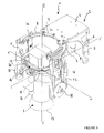
- FIG. 1 to 6 There is shown in Figures 1 to 6 a mechanical device 1 for pivoting a fixed element and more particularly a camera 2 according to three separate axes xx ', yy', zz '.
- the mechanical device 1 comprises a fixed support 3 and guide means and training to move, in a geometric coordinate system x, y, z arranged outside the fixed support 3, a camera 2.
- the guidance and drive means allow the device to be moved from 2 shots in vertical rotation and translation movements contained in the geometric coordinate system x, y, z in three distinct directions, having each an amplitude of 180 degrees.
- the geometric coordinate system x, y, z is centered at a point c which is outside fixed support 3.
- the fixed support 3 can be assembled or formed with that of a support and pre-stabilization to carry a load placed offset to the end of a deformable parallelogram, while maintaining the balance vertical and horizontal of this load as described and protected in a request patent in France belonging to the applicant.
- the support 3 consists of a horizontal upper plate 4 secured to square feet 5, joined together by a horizontal rod 6.
- the upper plate 4 has at least one edge 7 in the form of an arc of a circle at below which is guided in rotation a crown 8 having an open profile C-shaped
- the center of the crown 8 is on the vertical axis yy 'passing through the center c of the geometric reference x, y, z.
- the crown 8 is moved in rotation about its vertical axis yy 'and by relative to the fixed support 3 via a first geared motor 9 fixed under the plate 4 of said fixed support.
- the crown 8 is integral at its opening 10 with two slides 11, 12 arranged opposite one another and extending in a vertical direction down, i.e. below the crown 8.
- the opening 10 of the crown 8 allows vertical tilting up or towards the bottom of the camera 2.
- the camera 2 is integral opposite its objective 13 with a double crown 14 with closed profile.
- the double ring 14 has a first fixed external ring 19 to the interior of which is guided in rotation a second internal crown 20 on which is attached the camera 2.
- the outer ring 19 is integral around its periphery with two crosspieces parallels 15, 16 which are arranged opposite one another and which each carry at their free end a rotation axis 17, 18 guided respectively in the vertical slides 11 and 12.
- the outer ring 19 is integral around its periphery and between the crosspieces 15, 16 a second gear motor 21 allowing the rotational drive of the second internal crown 20 inside the first.
- the cross member 16 secured to the outer ring 19 carries a third motorcycle reducer 22 allowing the rotational movement of the device for taking views 2 around the axes of rotation 17, 18 guided in the vertical slides 11, 12.
- the mechanical device 1 comprises a fourth reduction motor, not shown, allowing the camera 2 to move in vertical translation inside the slides 11, 12.
- the third reduction motor 22 can be used to simultaneously move the gripping device of view 2 in rotation around the axes 17, 18 and in vertical translation in the slides 11, 12.
- the mechanical device 1 allows camera 2 to move in 180-degree rotations degrees independent of each other and in a vertical translation, from so that all the movements are contained in the coordinate system geometric x, y, z.
- each movement is independent of each other and is controlled by an external central unit not shown, controlled by a camera operator.
- center c of the geometric coordinate system x, y, z is offset laterally to be outside the fixed support 3 so that the socket device of view 2 can move in its different movements.
- each gear motor can be replaced by a device without other technical characteristics the object of the present invention.
Landscapes
- Engineering & Computer Science (AREA)
- General Engineering & Computer Science (AREA)
- Mechanical Engineering (AREA)
- Accessories Of Cameras (AREA)
- Studio Devices (AREA)
- Details Of Measuring And Other Instruments (AREA)
- Automatic Assembly (AREA)
- Devices For Conveying Motion By Means Of Endless Flexible Members (AREA)
- Details Of Cameras Including Film Mechanisms (AREA)
- Investigating Materials By The Use Of Optical Means Adapted For Particular Applications (AREA)
- Advancing Webs (AREA)
- Replacing, Conveying, And Pick-Finding For Filamentary Materials (AREA)
- Mechanical Control Devices (AREA)
- Toys (AREA)
- Radiography Using Non-Light Waves (AREA)
Abstract
Description
Claims (13)
- Dispositif mécanique pour le déplacement d'un appareil de prises de vue (2), caractérisé en ce qu'il comprend un support fixe (3) et des moyens de guidage et d'entraínement qui permettent de déplacer l'appareil de prises de vue (2) d'une part dans des mouvements de rotation et de translation verticale contenus dans un repère géométrique x, y, z disposé à l'extérieur du support fixe (3) et d'autre part dans des mouvements de rotation et de translation verticale contenus dans le repère géométrique x, y, z selon trois directions distinctes, ayant chacune une amplitude de 180 degrés.
- Dispositif mécanique suivant la revendication 1, caractérisé en ce que le repère géométrique x, y, z est centré en un point c qui se trouve à l'extérieur du support fixe (3).
- Dispositif mécanique suivant la revendication 1, caractérisé en ce qu'il comprend un support fixe (3) autour duquel pivote dans un plan horizontal une première couronne (8) solidaire dans un plan vertical de glissières parallèles (11, 12) permettant d'une part la translation verticale de l'appareil (2) par rapport au support (3) et d'autre part le pivotement angulaire de l'appareil (2) par rapport au support (3) dans un plan vertical et perpendiculaire à celui contenant la première couronne (8) et une double couronne (14) permettant le pivotement angulaire de l'appareil (2) autour de son axe principal.
- Dispositif mécanique suivant la revendication 1, caractérisé en ce que chaque déplacement en rotation et en translation de l'appareil de prise de vues (2) par rapport au support fixe (3) est assuré par un dispositif d'entraínement (9, 21, 22).
- Dispositif mécanique suivant la revendication 1, caractérisé en ce que le support fixe (3) est constitué d'une plaque supérieure horizontale (4) solidaire de pieds (5) en forme d'équerre réunis entre eux par une tige horizontale (6).
- Dispositif mécanique suivant la revendication 6, caractérisé en ce que la plaque supérieure (4) comporte au moins un bord (7) en forme d'arc de cercle au dessous duquel est guidée en rotation une couronne (8) présentant un profil ouvert en forme de C de manière que le centre de ladite couronne (8) soit porté par l'axe vertical yy' du repère géométrique x, y, z .
- Dispositif mécanique suivant la revendication 5, caractérisé en ce que la couronne (8) est déplacée en rotation autour de son axe vertical yy' et par rapport au support fixe (3) par l'intermédiaire d'un premier moto réducteur (9) fixé sous la plaque (4) dudit support fixe.
- Dispositif mécanique suivant la revendication 3, caractérisé en ce que la couronne (8) est solidaire au niveau d'une ouverture (10) de deux glissières (11, 12) disposées l'une en face de l'autre et s'étendant suivant une direction verticale vers le bas, c'est à dire, en dessous de la couronne (8), lesdites glissières coopérant respectivement avec des axes de rotation (17, 18) permettant d'une part le guidage et le déplacement vertical de l'appareil de prise de vues (2) par rapport au support (3) et d'autre part le pivotement angulaire de l'appareil (2) par rapport au support (3) dans un plan vertical et perpendiculaire à celui contenant la première couronne (8).
- Dispositif mécanique suivant la revendication 1, caractérisé en ce que l'appareil de prises de vues (2) est solidaire à l'opposé de son objectif (13) d'une double couronne (14) à profil fermé comportant une première couronne externe fixe (19) à l'intérieur de laquelle est guidée en rotation une seconde couronne interne (20) sur laquelle est fixé l'appareil de prises de vues (2).
- Dispositif mécanique suivant la revendication 9, caractérisé en ce que la couronne externe fixe (19) est solidaire sur son pourtour de deux traverses parallèles (15 ,16) qui sont disposées l'une en face de l'autre et qui portent chacune à leur extrémité libre un axe de rotation (17, 18) guidé respectivement dans les glissières verticales (11, 12) de la première couronne (8).
- Dispositif mécanique suivant la revendication 10, caractérisé en ce que la couronne externe (19) est solidaire sur son pourtour et entre les traverses (15, 16) d'un moto réducteur (21) permettant l'entraínement en rotation de la couronne interne (20) à l'intérieur de celle externe (19) et le déplacement de l'appareil de prises de vues (2) en rotation autour de son axe.
- Dispositif mécanique suivant la revendication 10, caractérisé en ce que La traverse (16) solidaire de la couronne externe (19) porte un autre moto réducteur (22) permettant le déplacement vertical, suivant l'axe yy', de l'appareil de prises de vues (2) à l'intérieur des glissières (11, 12) d'une position haute vers une position basse et inversement.
- Dispositif mécanique suivant la revendication 3, caractérisé en ce qu'il permet en fonction de chaque position angulaire de la couronne (8) autour de l'axe yy' obtenue par l'entraínement du moto réducteur (9), à l'appareil de prises de vues (2) de pivoter autour de son axe principal au moyen du moto réducteur (21), de pivoter autour de ses axes horizontaux (17, 18) d'une position maximale dont l'objectif (13) est dirigé vers le haut à une position maximale dont l'objectif (13) est dirigé vers le bas au moyen du moto réducteur (22) en passant par toutes les positions intermédiaires, et de se déplacer en translation verticale à l'intérieur des glissières (11, 12).
Applications Claiming Priority (2)
| Application Number | Priority Date | Filing Date | Title |
|---|---|---|---|
| FR0208790A FR2842279B1 (fr) | 2002-07-12 | 2002-07-12 | Dispositif mecanique pour le deplacement d'un appareil de prises de vues |
| FR0208790 | 2002-07-12 |
Publications (3)
| Publication Number | Publication Date |
|---|---|
| EP1380793A2 true EP1380793A2 (fr) | 2004-01-14 |
| EP1380793A3 EP1380793A3 (fr) | 2006-04-26 |
| EP1380793B1 EP1380793B1 (fr) | 2008-12-03 |
Family
ID=29725314
Family Applications (1)
| Application Number | Title | Priority Date | Filing Date |
|---|---|---|---|
| EP03356109A Expired - Lifetime EP1380793B1 (fr) | 2002-07-12 | 2003-07-10 | Dispositif mécanique pour le déplacement d'un appareil de prises de vues |
Country Status (5)
| Country | Link |
|---|---|
| EP (1) | EP1380793B1 (fr) |
| AT (1) | ATE416343T1 (fr) |
| DE (1) | DE60324991D1 (fr) |
| ES (1) | ES2318100T3 (fr) |
| FR (1) | FR2842279B1 (fr) |
Cited By (8)
| Publication number | Priority date | Publication date | Assignee | Title |
|---|---|---|---|---|
| EP1746332A1 (fr) * | 2005-07-20 | 2007-01-24 | Piumaworld S.r.l. | Dispositif de support pour caméras de télévision ou caméras-film |
| GB2433119A (en) * | 2005-12-06 | 2007-06-13 | Bosch Gmbh Robert | A surveillance camera gimbal mechanism |
| US7621680B2 (en) | 2005-12-06 | 2009-11-24 | Robert Bosch Gmbh | In-ceiling surveillance housing |
| CN103470925A (zh) * | 2013-09-04 | 2013-12-25 | 中国科学院深圳先进技术研究院 | 自动控制空间转动装置 |
| EP2862347A4 (fr) * | 2012-06-19 | 2016-03-09 | Chapman Leonard Studio Equip | Tête de caméra à mouvement de panoramique, de roulis et d'inclinaison |
| CN111810818A (zh) * | 2020-06-11 | 2020-10-23 | 福州玮烨智能科技有限公司 | 一种基于互联网的三维数字化园区安防监控装置 |
| WO2022069093A1 (fr) * | 2020-10-01 | 2022-04-07 | 4Movie Bvba | Système de stabilisation de caméra |
| US11852959B2 (en) | 2020-10-01 | 2023-12-26 | 4Movie Bvba | Camera stabilization system |
Citations (4)
| Publication number | Priority date | Publication date | Assignee | Title |
|---|---|---|---|---|
| FR2538878A1 (fr) * | 1983-01-03 | 1984-07-06 | Production Creation Audiovisue | Dispositif pour orienter un appareil de prise de vues |
| US5617762A (en) * | 1995-03-10 | 1997-04-08 | Kirsch; Jerry | Miniature positioning device |
| EP0966154A1 (fr) * | 1998-06-16 | 1999-12-22 | Movie Engineering srl | Méthode et dispositif de commande à distance sur trois axes pour caméra vidéo ou cinématographique |
| US6027085A (en) * | 1997-07-28 | 2000-02-22 | Ruther; Chris | Camera holder for attachment to a tilt head |
-
2002
- 2002-07-12 FR FR0208790A patent/FR2842279B1/fr not_active Expired - Fee Related
-
2003
- 2003-07-10 DE DE60324991T patent/DE60324991D1/de not_active Expired - Lifetime
- 2003-07-10 EP EP03356109A patent/EP1380793B1/fr not_active Expired - Lifetime
- 2003-07-10 ES ES03356109T patent/ES2318100T3/es not_active Expired - Lifetime
- 2003-07-10 AT AT03356109T patent/ATE416343T1/de active
Patent Citations (4)
| Publication number | Priority date | Publication date | Assignee | Title |
|---|---|---|---|---|
| FR2538878A1 (fr) * | 1983-01-03 | 1984-07-06 | Production Creation Audiovisue | Dispositif pour orienter un appareil de prise de vues |
| US5617762A (en) * | 1995-03-10 | 1997-04-08 | Kirsch; Jerry | Miniature positioning device |
| US6027085A (en) * | 1997-07-28 | 2000-02-22 | Ruther; Chris | Camera holder for attachment to a tilt head |
| EP0966154A1 (fr) * | 1998-06-16 | 1999-12-22 | Movie Engineering srl | Méthode et dispositif de commande à distance sur trois axes pour caméra vidéo ou cinématographique |
Cited By (13)
| Publication number | Priority date | Publication date | Assignee | Title |
|---|---|---|---|---|
| EP1746332A1 (fr) * | 2005-07-20 | 2007-01-24 | Piumaworld S.r.l. | Dispositif de support pour caméras de télévision ou caméras-film |
| GB2433119A (en) * | 2005-12-06 | 2007-06-13 | Bosch Gmbh Robert | A surveillance camera gimbal mechanism |
| US7534057B2 (en) | 2005-12-06 | 2009-05-19 | Robert Bosch Gmbh | Surveillance camera gimbal mechanism |
| GB2433119B (en) * | 2005-12-06 | 2009-09-09 | Bosch Gmbh Robert | Surveillance camera gimbal mechanism |
| US7621680B2 (en) | 2005-12-06 | 2009-11-24 | Robert Bosch Gmbh | In-ceiling surveillance housing |
| EP2862347A4 (fr) * | 2012-06-19 | 2016-03-09 | Chapman Leonard Studio Equip | Tête de caméra à mouvement de panoramique, de roulis et d'inclinaison |
| CN103470925B (zh) * | 2013-09-04 | 2015-07-08 | 中国科学院深圳先进技术研究院 | 自动控制空间转动装置 |
| CN103470925A (zh) * | 2013-09-04 | 2013-12-25 | 中国科学院深圳先进技术研究院 | 自动控制空间转动装置 |
| CN111810818A (zh) * | 2020-06-11 | 2020-10-23 | 福州玮烨智能科技有限公司 | 一种基于互联网的三维数字化园区安防监控装置 |
| WO2022069093A1 (fr) * | 2020-10-01 | 2022-04-07 | 4Movie Bvba | Système de stabilisation de caméra |
| BE1028664B1 (nl) * | 2020-10-01 | 2022-05-04 | 4Movie | Camerastabilisatiesysteem |
| US11543738B2 (en) | 2020-10-01 | 2023-01-03 | 4Movie Bvba | Camera stabilization system |
| US11852959B2 (en) | 2020-10-01 | 2023-12-26 | 4Movie Bvba | Camera stabilization system |
Also Published As
| Publication number | Publication date |
|---|---|
| EP1380793B1 (fr) | 2008-12-03 |
| DE60324991D1 (de) | 2009-01-15 |
| FR2842279A1 (fr) | 2004-01-16 |
| ATE416343T1 (de) | 2008-12-15 |
| EP1380793A3 (fr) | 2006-04-26 |
| FR2842279B1 (fr) | 2005-01-28 |
| ES2318100T3 (es) | 2009-05-01 |
Similar Documents
| Publication | Publication Date | Title |
|---|---|---|
| EP1854591B1 (fr) | Robot parallèle | |
| CA2678649A1 (fr) | Robot manipulateur compact | |
| EP0308347A1 (fr) | Appareil manipulateur de tête de test à suspension ameliorée | |
| FR2578472A1 (fr) | Perfectionnements aux robots industriels du type a structure spherique | |
| EP1600730A1 (fr) | Appareil de lecture de contour comportant un palpeur mobile en rotation | |
| EP1380793A2 (fr) | Dispositif mécanique pour le déplacement d'un appareil de prises de vues | |
| EP0702906B1 (fr) | Paire d'articulations à manoeuvres synchronisées pour la fixation d'une visière escamotable sur un casque | |
| EP2650583B1 (fr) | Bras porteur de charge réglable, dispositif de suspension d'une charge | |
| CH625867A5 (fr) | ||
| EP0466661B1 (fr) | Parasol | |
| FR2612406A1 (fr) | Appareil d'exercice musculaire | |
| FR2689073A1 (fr) | Appareillage de manutention de charges allongées sur le toit d'un véhicule. | |
| FR2822102A1 (fr) | Selle de sculpteur-modeleur | |
| EP0105812A1 (fr) | Appareil d'échotomographie d'organes externes, notamment des glandes mammaires | |
| FR2633487A1 (fr) | Dispositif de prelevement de matieres granuleuses ou pulverulentes | |
| EP0619040B1 (fr) | Support pour les bras et mains d'un utilisateur d'un instrument ou appareil a clavier, a dessiner, a tricoter | |
| EP1317171A1 (fr) | Dispositif de support pour un outil coupant, notamment un taille haie | |
| FR2791731A1 (fr) | Dispositif de securite pour l'adossement d'une echelle deployee en hauteur | |
| FR3043032A1 (fr) | Marchepied escamotable pour vehicule automobile. | |
| FR3041312A1 (fr) | Poignee pliante de poussette pour enfant | |
| WO2011138526A1 (fr) | Batteur melangeur a tete pivotante | |
| CH622997A5 (en) | Device for assisting with opening up a folding caravan | |
| EP3335824A1 (fr) | Système pour extraire une électrode à souder | |
| FR2920685A1 (fr) | Dispositif de support, de positionnement et de guidage d'un outil | |
| FR2843543A1 (fr) | Perfectionnement a un dispositif permettant d'effectuer des exercices physiques |
Legal Events
| Date | Code | Title | Description |
|---|---|---|---|
| PUAI | Public reference made under article 153(3) epc to a published international application that has entered the european phase |
Free format text: ORIGINAL CODE: 0009012 |
|
| AK | Designated contracting states |
Kind code of ref document: A2 Designated state(s): AT BE BG CH CY CZ DE DK EE ES FI FR GB GR HU IE IT LI LU MC NL PT RO SE SI SK TR |
|
| AX | Request for extension of the european patent |
Extension state: AL LT LV MK |
|
| 17P | Request for examination filed |
Effective date: 20040714 |
|
| RAP1 | Party data changed (applicant data changed or rights of an application transferred) |
Owner name: KACZEK, FREDERIC-GERARD |
|
| RIN1 | Information on inventor provided before grant (corrected) |
Inventor name: KACZEK, FREDERIC-GERARD |
|
| PUAL | Search report despatched |
Free format text: ORIGINAL CODE: 0009013 |
|
| AK | Designated contracting states |
Kind code of ref document: A3 Designated state(s): AT BE BG CH CY CZ DE DK EE ES FI FR GB GR HU IE IT LI LU MC NL PT RO SE SI SK TR |
|
| AX | Request for extension of the european patent |
Extension state: AL LT LV MK |
|
| AKX | Designation fees paid |
Designated state(s): AT BE BG CH CY CZ DE DK EE ES FI FR GB GR HU IE IT LI LU MC NL PT RO SE SI SK TR |
|
| 17Q | First examination report despatched |
Effective date: 20080109 |
|
| GRAP | Despatch of communication of intention to grant a patent |
Free format text: ORIGINAL CODE: EPIDOSNIGR1 |
|
| RIN1 | Information on inventor provided before grant (corrected) |
Inventor name: PELERIN, JEAN-MICHEL |
|
| GRAS | Grant fee paid |
Free format text: ORIGINAL CODE: EPIDOSNIGR3 |
|
| GRAS | Grant fee paid |
Free format text: ORIGINAL CODE: EPIDOSNIGR3 |
|
| GRAA | (expected) grant |
Free format text: ORIGINAL CODE: 0009210 |
|
| AK | Designated contracting states |
Kind code of ref document: B1 Designated state(s): AT BE BG CH CY CZ DE DK EE ES FI FR GB GR HU IE IT LI LU MC NL PT RO SE SI SK TR |
|
| REG | Reference to a national code |
Ref country code: GB Ref legal event code: FG4D Free format text: NOT ENGLISH |
|
| REG | Reference to a national code |
Ref country code: CH Ref legal event code: EP |
|
| REG | Reference to a national code |
Ref country code: IE Ref legal event code: FG4D Free format text: LANGUAGE OF EP DOCUMENT: FRENCH |
|
| REF | Corresponds to: |
Ref document number: 60324991 Country of ref document: DE Date of ref document: 20090115 Kind code of ref document: P |
|
| REG | Reference to a national code |
Ref country code: ES Ref legal event code: FG2A Ref document number: 2318100 Country of ref document: ES Kind code of ref document: T3 |
|
| NLV1 | Nl: lapsed or annulled due to failure to fulfill the requirements of art. 29p and 29m of the patents act | ||
| PG25 | Lapsed in a contracting state [announced via postgrant information from national office to epo] |
Ref country code: NL Free format text: LAPSE BECAUSE OF FAILURE TO SUBMIT A TRANSLATION OF THE DESCRIPTION OR TO PAY THE FEE WITHIN THE PRESCRIBED TIME-LIMIT Effective date: 20081203 Ref country code: SI Free format text: LAPSE BECAUSE OF FAILURE TO SUBMIT A TRANSLATION OF THE DESCRIPTION OR TO PAY THE FEE WITHIN THE PRESCRIBED TIME-LIMIT Effective date: 20081203 Ref country code: FI Free format text: LAPSE BECAUSE OF FAILURE TO SUBMIT A TRANSLATION OF THE DESCRIPTION OR TO PAY THE FEE WITHIN THE PRESCRIBED TIME-LIMIT Effective date: 20081203 |
|
| REG | Reference to a national code |
Ref country code: IE Ref legal event code: FD4D |
|
| PG25 | Lapsed in a contracting state [announced via postgrant information from national office to epo] |
Ref country code: BG Free format text: LAPSE BECAUSE OF FAILURE TO SUBMIT A TRANSLATION OF THE DESCRIPTION OR TO PAY THE FEE WITHIN THE PRESCRIBED TIME-LIMIT Effective date: 20090303 Ref country code: RO Free format text: LAPSE BECAUSE OF FAILURE TO SUBMIT A TRANSLATION OF THE DESCRIPTION OR TO PAY THE FEE WITHIN THE PRESCRIBED TIME-LIMIT Effective date: 20081203 Ref country code: EE Free format text: LAPSE BECAUSE OF FAILURE TO SUBMIT A TRANSLATION OF THE DESCRIPTION OR TO PAY THE FEE WITHIN THE PRESCRIBED TIME-LIMIT Effective date: 20081203 Ref country code: IE Free format text: LAPSE BECAUSE OF FAILURE TO SUBMIT A TRANSLATION OF THE DESCRIPTION OR TO PAY THE FEE WITHIN THE PRESCRIBED TIME-LIMIT Effective date: 20081203 |
|
| PG25 | Lapsed in a contracting state [announced via postgrant information from national office to epo] |
Ref country code: CZ Free format text: LAPSE BECAUSE OF FAILURE TO SUBMIT A TRANSLATION OF THE DESCRIPTION OR TO PAY THE FEE WITHIN THE PRESCRIBED TIME-LIMIT Effective date: 20081203 Ref country code: PT Free format text: LAPSE BECAUSE OF FAILURE TO SUBMIT A TRANSLATION OF THE DESCRIPTION OR TO PAY THE FEE WITHIN THE PRESCRIBED TIME-LIMIT Effective date: 20090504 Ref country code: SE Free format text: LAPSE BECAUSE OF FAILURE TO SUBMIT A TRANSLATION OF THE DESCRIPTION OR TO PAY THE FEE WITHIN THE PRESCRIBED TIME-LIMIT Effective date: 20090303 |
|
| PG25 | Lapsed in a contracting state [announced via postgrant information from national office to epo] |
Ref country code: SK Free format text: LAPSE BECAUSE OF FAILURE TO SUBMIT A TRANSLATION OF THE DESCRIPTION OR TO PAY THE FEE WITHIN THE PRESCRIBED TIME-LIMIT Effective date: 20081203 |
|
| PLBE | No opposition filed within time limit |
Free format text: ORIGINAL CODE: 0009261 |
|
| STAA | Information on the status of an ep patent application or granted ep patent |
Free format text: STATUS: NO OPPOSITION FILED WITHIN TIME LIMIT |
|
| PG25 | Lapsed in a contracting state [announced via postgrant information from national office to epo] |
Ref country code: DK Free format text: LAPSE BECAUSE OF FAILURE TO SUBMIT A TRANSLATION OF THE DESCRIPTION OR TO PAY THE FEE WITHIN THE PRESCRIBED TIME-LIMIT Effective date: 20081203 |
|
| 26N | No opposition filed |
Effective date: 20090904 |
|
| PG25 | Lapsed in a contracting state [announced via postgrant information from national office to epo] |
Ref country code: MC Free format text: LAPSE BECAUSE OF NON-PAYMENT OF DUE FEES Effective date: 20090731 |
|
| REG | Reference to a national code |
Ref country code: CH Ref legal event code: PL |
|
| PG25 | Lapsed in a contracting state [announced via postgrant information from national office to epo] |
Ref country code: LI Free format text: LAPSE BECAUSE OF NON-PAYMENT OF DUE FEES Effective date: 20090731 Ref country code: CH Free format text: LAPSE BECAUSE OF NON-PAYMENT OF DUE FEES Effective date: 20090731 |
|
| PG25 | Lapsed in a contracting state [announced via postgrant information from national office to epo] |
Ref country code: GR Free format text: LAPSE BECAUSE OF FAILURE TO SUBMIT A TRANSLATION OF THE DESCRIPTION OR TO PAY THE FEE WITHIN THE PRESCRIBED TIME-LIMIT Effective date: 20090304 |
|
| PG25 | Lapsed in a contracting state [announced via postgrant information from national office to epo] |
Ref country code: IT Free format text: LAPSE BECAUSE OF FAILURE TO SUBMIT A TRANSLATION OF THE DESCRIPTION OR TO PAY THE FEE WITHIN THE PRESCRIBED TIME-LIMIT Effective date: 20081203 |
|
| PG25 | Lapsed in a contracting state [announced via postgrant information from national office to epo] |
Ref country code: LU Free format text: LAPSE BECAUSE OF NON-PAYMENT OF DUE FEES Effective date: 20090710 |
|
| PG25 | Lapsed in a contracting state [announced via postgrant information from national office to epo] |
Ref country code: HU Free format text: LAPSE BECAUSE OF FAILURE TO SUBMIT A TRANSLATION OF THE DESCRIPTION OR TO PAY THE FEE WITHIN THE PRESCRIBED TIME-LIMIT Effective date: 20090604 |
|
| PG25 | Lapsed in a contracting state [announced via postgrant information from national office to epo] |
Ref country code: TR Free format text: LAPSE BECAUSE OF FAILURE TO SUBMIT A TRANSLATION OF THE DESCRIPTION OR TO PAY THE FEE WITHIN THE PRESCRIBED TIME-LIMIT Effective date: 20081203 |
|
| PG25 | Lapsed in a contracting state [announced via postgrant information from national office to epo] |
Ref country code: CY Free format text: LAPSE BECAUSE OF FAILURE TO SUBMIT A TRANSLATION OF THE DESCRIPTION OR TO PAY THE FEE WITHIN THE PRESCRIBED TIME-LIMIT Effective date: 20081203 |
|
| REG | Reference to a national code |
Ref country code: FR Ref legal event code: PLFP Year of fee payment: 13 |
|
| PGFP | Annual fee paid to national office [announced via postgrant information from national office to epo] |
Ref country code: GB Payment date: 20150723 Year of fee payment: 13 Ref country code: ES Payment date: 20150715 Year of fee payment: 13 |
|
| PGFP | Annual fee paid to national office [announced via postgrant information from national office to epo] |
Ref country code: FR Payment date: 20150730 Year of fee payment: 13 Ref country code: BE Payment date: 20150731 Year of fee payment: 13 Ref country code: AT Payment date: 20150727 Year of fee payment: 13 |
|
| PG25 | Lapsed in a contracting state [announced via postgrant information from national office to epo] |
Ref country code: BE Free format text: LAPSE BECAUSE OF NON-PAYMENT OF DUE FEES Effective date: 20160731 |
|
| REG | Reference to a national code |
Ref country code: AT Ref legal event code: MM01 Ref document number: 416343 Country of ref document: AT Kind code of ref document: T Effective date: 20160710 |
|
| GBPC | Gb: european patent ceased through non-payment of renewal fee |
Effective date: 20160710 |
|
| PG25 | Lapsed in a contracting state [announced via postgrant information from national office to epo] |
Ref country code: FR Free format text: LAPSE BECAUSE OF NON-PAYMENT OF DUE FEES Effective date: 20160801 |
|
| REG | Reference to a national code |
Ref country code: FR Ref legal event code: ST Effective date: 20170331 |
|
| PG25 | Lapsed in a contracting state [announced via postgrant information from national office to epo] |
Ref country code: GB Free format text: LAPSE BECAUSE OF NON-PAYMENT OF DUE FEES Effective date: 20160710 Ref country code: AT Free format text: LAPSE BECAUSE OF NON-PAYMENT OF DUE FEES Effective date: 20160710 |
|
| PGFP | Annual fee paid to national office [announced via postgrant information from national office to epo] |
Ref country code: DE Payment date: 20170929 Year of fee payment: 15 |
|
| PG25 | Lapsed in a contracting state [announced via postgrant information from national office to epo] |
Ref country code: ES Free format text: LAPSE BECAUSE OF NON-PAYMENT OF DUE FEES Effective date: 20160711 |
|
| REG | Reference to a national code |
Ref country code: ES Ref legal event code: FD2A Effective date: 20180622 |
|
| REG | Reference to a national code |
Ref country code: DE Ref legal event code: R119 Ref document number: 60324991 Country of ref document: DE |
|
| PG25 | Lapsed in a contracting state [announced via postgrant information from national office to epo] |
Ref country code: DE Free format text: LAPSE BECAUSE OF NON-PAYMENT OF DUE FEES Effective date: 20190201 |