EP1296173B1 - Multiple sharing type display device - Google Patents
Multiple sharing type display device Download PDFInfo
- Publication number
- EP1296173B1 EP1296173B1 EP01945723A EP01945723A EP1296173B1 EP 1296173 B1 EP1296173 B1 EP 1296173B1 EP 01945723 A EP01945723 A EP 01945723A EP 01945723 A EP01945723 A EP 01945723A EP 1296173 B1 EP1296173 B1 EP 1296173B1
- Authority
- EP
- European Patent Office
- Prior art keywords
- display
- display device
- user
- display surface
- mask
- Prior art date
- Legal status (The legal status is an assumption and is not a legal conclusion. Google has not performed a legal analysis and makes no representation as to the accuracy of the status listed.)
- Expired - Lifetime
Links
Images


Classifications
-
- G—PHYSICS
- G06—COMPUTING OR CALCULATING; COUNTING
- G06F—ELECTRIC DIGITAL DATA PROCESSING
- G06F3/00—Input arrangements for transferring data to be processed into a form capable of being handled by the computer; Output arrangements for transferring data from processing unit to output unit, e.g. interface arrangements
- G06F3/01—Input arrangements or combined input and output arrangements for interaction between user and computer
- G06F3/011—Arrangements for interaction with the human body, e.g. for user immersion in virtual reality
-
- G—PHYSICS
- G02—OPTICS
- G02B—OPTICAL ELEMENTS, SYSTEMS OR APPARATUS
- G02B27/00—Optical systems or apparatus not provided for by any of the groups G02B1/00 - G02B26/00, G02B30/00
- G02B27/01—Head-up displays
- G02B27/017—Head mounted
-
- G—PHYSICS
- G02—OPTICS
- G02B—OPTICAL ELEMENTS, SYSTEMS OR APPARATUS
- G02B27/00—Optical systems or apparatus not provided for by any of the groups G02B1/00 - G02B26/00, G02B30/00
- G02B27/01—Head-up displays
- G02B27/017—Head mounted
- G02B27/0172—Head mounted characterised by optical features
-
- G—PHYSICS
- G02—OPTICS
- G02B—OPTICAL ELEMENTS, SYSTEMS OR APPARATUS
- G02B30/00—Optical systems or apparatus for producing three-dimensional [3D] effects, e.g. stereoscopic images
- G02B30/20—Optical systems or apparatus for producing three-dimensional [3D] effects, e.g. stereoscopic images by providing first and second parallax images to an observer's left and right eyes
- G02B30/34—Stereoscopes providing a stereoscopic pair of separated images corresponding to parallactically displaced views of the same object, e.g. 3D slide viewers
-
- H—ELECTRICITY
- H04—ELECTRIC COMMUNICATION TECHNIQUE
- H04N—PICTORIAL COMMUNICATION, e.g. TELEVISION
- H04N13/00—Stereoscopic video systems; Multi-view video systems; Details thereof
- H04N13/30—Image reproducers
- H04N13/302—Image reproducers for viewing without the aid of special glasses, i.e. using autostereoscopic displays
- H04N13/32—Image reproducers for viewing without the aid of special glasses, i.e. using autostereoscopic displays using arrays of controllable light sources; using moving apertures or moving light sources
-
- H—ELECTRICITY
- H04—ELECTRIC COMMUNICATION TECHNIQUE
- H04N—PICTORIAL COMMUNICATION, e.g. TELEVISION
- H04N13/00—Stereoscopic video systems; Multi-view video systems; Details thereof
- H04N13/30—Image reproducers
- H04N13/366—Image reproducers using viewer tracking
- H04N13/368—Image reproducers using viewer tracking for two or more viewers
-
- H—ELECTRICITY
- H04—ELECTRIC COMMUNICATION TECHNIQUE
- H04N—PICTORIAL COMMUNICATION, e.g. TELEVISION
- H04N13/00—Stereoscopic video systems; Multi-view video systems; Details thereof
- H04N13/30—Image reproducers
- H04N13/398—Synchronisation thereof; Control thereof
-
- G—PHYSICS
- G02—OPTICS
- G02B—OPTICAL ELEMENTS, SYSTEMS OR APPARATUS
- G02B27/00—Optical systems or apparatus not provided for by any of the groups G02B1/00 - G02B26/00, G02B30/00
- G02B27/01—Head-up displays
- G02B27/017—Head mounted
- G02B2027/0178—Eyeglass type
-
- H—ELECTRICITY
- H04—ELECTRIC COMMUNICATION TECHNIQUE
- H04N—PICTORIAL COMMUNICATION, e.g. TELEVISION
- H04N13/00—Stereoscopic video systems; Multi-view video systems; Details thereof
- H04N13/20—Image signal generators
- H04N13/286—Image signal generators having separate monoscopic and stereoscopic modes
-
- H—ELECTRICITY
- H04—ELECTRIC COMMUNICATION TECHNIQUE
- H04N—PICTORIAL COMMUNICATION, e.g. TELEVISION
- H04N13/00—Stereoscopic video systems; Multi-view video systems; Details thereof
- H04N13/30—Image reproducers
- H04N13/332—Displays for viewing with the aid of special glasses or head-mounted displays [HMD]
- H04N13/339—Displays for viewing with the aid of special glasses or head-mounted displays [HMD] using spatial multiplexing
-
- H—ELECTRICITY
- H04—ELECTRIC COMMUNICATION TECHNIQUE
- H04N—PICTORIAL COMMUNICATION, e.g. TELEVISION
- H04N13/00—Stereoscopic video systems; Multi-view video systems; Details thereof
- H04N13/30—Image reproducers
- H04N13/332—Displays for viewing with the aid of special glasses or head-mounted displays [HMD]
- H04N13/344—Displays for viewing with the aid of special glasses or head-mounted displays [HMD] with head-mounted left-right displays
Definitions
- the present invention relates to a display device.
- it is related to display device allowing a plurality of users to share a common display device.
- Techniques of displaying three-dimensional images are generally classified into a technique where a stereoscopic image is formed using an appropriate method and having the viewer of such image view it without assistance, and a binocular disparity technique devised so that, instead of a stereoscopic image, a right-eye view and a left-eye view of a flat image is formed and the right-eye view is viewed by the right eye and the left-eye view is viewed by the left eye.
- Typical examples of the former include holography and integral photography, and the latter includes three-dimensional movies where polarized glasses or liquid crystal shutters are used, and three-dimensional television using lenticular film.
- the binocular disparity technique is based on ergonomics, and provides three-dimensional images giving an enhanced 'real' feeling, and superior immersion and sensory feelings. However, it is not possible to freely change the viewpoint from which the three-dimensional object shown is viewed to coordinate with the user's movements using this technique by itself.
- a method which modifies the three-dimensional image in accordance with the viewpoint and position of the viewer a device (e.g., magnetic sensors or the like) worn for measuring the position of the head (viewpoint) of the viewer plus the binocular disparity technique allows the three-dimensional image to be viewed relative to the viewpoint position.
- a device e.g., magnetic sensors or the like
- the number of users for which viewpoint movement within real-space can be reflected in the virtual world is limited to one person for each display.
- the display frequency is in inverse proportion to the number of users, which cause problems such as flickers to occur.
- the number of display devices matching the number of users or a large-scale device is required, which is problematic in terms of price.
- EP 0 899 969 A2 describes a three-dimensional image reconstructing apparatus for reconstructing a three-dimensional image and permitting the three-dimensional image to be observed at an observation position by use of an image display for displaying image information, a space optical modulator for forming a fine aperture, an optical system disposed near the space optical modulator, and a controller for controlling the image display and the space optical modulator so that some rays outgoing through the fine aperture of the space optical modulator and the optical system out of rays from the image information displayed on the image display pass a predetermined point in a three-dimensional space within a fixed period, wherein a distance between two closest rays passing the predetermined point and reaching the observation position is determined based on a diameter of a pupil of an observer.
- a pinhole panel serves for forming a fine aperture.
- the pinhole panel is composed of a space optical modulator (spatial light modulating means) of a transmission type, which is, for example, a liquid crystal display capable of electronically changing the transmittance at an arbitrary position to form an optical pinhole.
- the pinhole moves at high speed and in constant period over the entire area of the pinhole panel 3.
- US 5,855,425 describes a stereoscopic display in which a left eye image is projected from a first projector, and a right eye image is projected from a second projector.
- the images projected from the projectors pass through a plurality of light transmitting portions in a light shading means. Consequently, pairs of right and left eye images are formed in a vertical stripe shape on a dispersion panel.
- Each of the pairs of right and left eye images formed on the dispersion panel is introduced into the right and left eyes of a viewer upon being separated by a parallax barrier used as a separating means.
- a sensor detects the position of the viewer.
- a driving and control unit changes the positions of the light transmitting portions in the light shading means on the basis of an output of the sensor.
- An object of the present invention is to provide a multi-person shared display device capable of displaying in response to viewpoint movement in real space. Another object of the present invention is to provide a multi-person shared display device capable of displaying a three dimensional image.
- the proposed multi-person shared display device uses a display mask in which a hole is formed and covers the display device so as to hide portions besides the hole, allowing different display regions upon the display device to be set in accordance with the viewpoint position within real space of each user. This makes it possible to perform display in response to viewpoint movements of a plurality of users.
- FIG 1(a) is a diagram showing a configuration of a multi-person shared three-dimensional display device according to an embodiment of the present invention.
- two users 140 and 150 of a multi-person shared three-dimensional display device each have on liquid crystal shutter glasses 142, 152, respectively, and also have a respective position sensor 144, 154 attached.
- the users view an image displayed upon a display screen 110 via the liquid crystal shutters.
- the liquid crystal shutter glasses 142, 152, position sensors 144, 154, and display device 110 are connected to a processing device 130. In conformity with the input from the position sensors, the processing apparatus 130 displays an image upon the display at a region corresponding to each respective user.
- the display device 110 is configured from a display 112 and a display mask 114, which covers and hides a portion thereof.
- the display mask 114 is set at a position separated only an appropriate distance away from a display surface 116.
- a hole 118 is formed in the display mask 114, and through only that portion can the surface 116 of the display 112 be seen.
- the viewable region upon the display surface varies depending on the viewpoint position of the user.
- the viewpoint position of a user moves
- the region viewable by the user also changes depending on that movement. Accordingly, by detecting viewpoint position using the position sensor and displaying at a region befitting that viewpoint position, it is possible to adapt to the movement of the viewpoint position of the user.
- a magnetic sensor having 6 degrees of freedom can be used as the viewpoint position detection sensor.
- the magnetic sensor can detect the current position by detecting magnetic flux cutoff in every respective direction x, y, and z. Assuming that the direction of the line of sight faces the center of the hole upon the mask and that a line connecting both eyes parallels the horizontal surface, that direction of the line of sight can be calculated in real time from the viewpoint position detected.
- the position detection sensor may be constructed integrated in the liquid crystal shutter glasses.
- the processing device 130 is provided comprising projecting an image for the respective right and left viewpoint derived and time-divided, alternating displaying upon a display 112 synchronous to the liquid crystal shutters.
- this system displays enlargement thereof.
- This allows, for example, a display frequency of 120 Hz to be divided into 60 Hz to show the right and left images.
- the liquid crystal shutters switch between both right and left, viewable and non-viewable, by synchronizing with the image refresh rate.
- the fact that the display 112 is viewed through the liquid crystal shutter glasses makes it possible to obtain images that correspond to the respective right and left viewpoints, thereby allowing three-dimensional viewing.
- the top and lower halves are output one at a time; however, in what manner division and display are carried out, or whether display is carried out without division, or if display is accomplished through interlacing or so forth, can be freely set. Further, besides a display device that provides a normal light-emitting surface to be directly viewed, a projector type display device may also be used.
- the positional sensor is constructed integrated with glasses incorporating liquid crystal shutters, error is especially small, and it is possible to calculate the viewpoint position from the positional information obtained by the positional sensor, as described above.
- the method where the projection surface and the display surface are made to match can be used as a most basic method of appropriately setting the projection surface.
- this method in the case where the absolute position of the display surface within the real world is invariant, the absolute position of the projection surface within the virtual world is also invariant, there is no need to consider correction of the absolute position of the projection surface, and it becomes acceptable to consider only the relative position from the viewpoint.
- the projection surface should be set to match the display surface in the simplistic manner described next.
- FIG 5(b) shows an example of a display screen in the case where a relationship among the projection surface, the display surface, and the virtual object such as that shown in FIG 5(a) is assumed. If a relationship such as that shown in FIG 5(a) is assumed, that which is to be shown upon the display surface 116 in the real world is an enlarged image.
- a display region corresponding to the viewpoint position of the user is derived and image rendering is performed in that region.
- the display region corresponding to the position of the user viewpoint is also circular, and the position of the center thereof is determined in conformity with the following two parameters.
- the distance between the mask 114 and the display surface 116 is fixed.
- the center of the display surface 116 is made the origin, the coordinate system having the center of display surface 116 as the origin is set as shown in FIG 6 , with the viewpoint upon that coordinate system, the distance between the mask and the display surface, and the position of the center of the display region being defined as the following:
- the radius defining the magnitude of the circular display region 242 is derived from the following three parameters:
- radius of the hole 118 upon the mask 114 and the radius of the display region 242 are respectively defined as the following:
- the display has a rectangular shape with a width of 1360 mm and height of 1020 mm, and from the surface of the floor the height of the display surface is 1000 mm.
- the distance between the display mask and the display surface is 150 mm and the radius of the mask hole is 200 mm.
- the system of the embodiment described above is an example where the display surface is placed horizontally; alternatively, the display surface may naturally be placed vertically or at a slant. If the display is made to be the projection type, it is possible to achieve a large screen display. In addition, in order to configure a large display, a plurality of displays may be combined.
- FIG 8 shows a theatre-style multi-person shared three-dimensional display device capable of being used by multiple persons.
- the theatre style multi-person shared three-dimensional display device for example, given a width of 25 m, height of 18 m, distance of 6 m between the display mask and the display surface, radius of 0.5 m for the mask hole of the display mask, a maximum of forty-eight persons can simultaneously view the respective videos.
- the display mask is configured with liquid crystal, it is possible to control the radius, shape, and location of the hole of the display mask through the permeability and non-permeability of the liquid crystal.
- a mechanical mechanism such as an aperture mechanism or the like can be used.
- glasses with attached shutters are utilized wherein the opening and closing of the shutters is synchronized and images corresponding to the left/right line of sight are displayed to obtain a three-dimensional image; however, the present invention is not limited to this method for obtaining a three-dimensional view.
- a filter based on polarization or color may be used as the glasses to be worn to segregate images corresponding to the left and right lines of sight.
- FIG 9 A configuration example corresponding to such entertainment purposes is shown in FIG 9 .
- audience members traveling aboard carts 421, 422, and 423, respectively view a display 416 via a hole 418 in display mask 414.
- FIG 9(b) shows a configuration where a three-dimensional image displayed on a display 516 is viewed through a hole 518 in a display mask 514 while a plurality of audience members are moving about a central stage.
- FIG 10 An example of this configuration is shown in FIG 10 .
- This configuration is a fundamentally similar configuration as the multi-person shared three-dimensional display device shown in FIG 1 .
- sensors 162, 164, 166 are attached to each audience member and the respective position of each audience member is detected through a processing device 130.
- the processing device 130 in conformity with the detected positions, performs display corresponding to each person on the display regions 224, 226, 228 respectively associated with each audience member.
- the multi-person shared display device of the present invention it is possible to perform appropriate display corresponding to viewpoint movement for a plurality of persons.
- the relative positions between the viewpoint and projection surface in the virtual world are appropriately corrected corresponding to changes in the relative positions between the viewpoint and projection surface in the real world.
- a three-dimensional image can be displayed for a plurality of moving users having neither flickering nor spatial distortion.
- regions of viewpoint movement allowing a user to obtain an appropriate image have also been described in detail.
- the present invention is applicable to not only a stand-alone computer system, but may also be made applicable to, for example, a client server system or the like configured from a plurality of systems.
- Such storage media includes floppy disks, CD-ROMS, magnetic tape, and ROM cassettes.
- an image rendered upon a screen in compliance with the individual audience member positions is viewed via a hole of an appropriate size an appropriate distance from the screen.
- a hole of an appropriate size an appropriate distance from the screen.
- Technology relating to such a multi-person shared display device is capable of wide range industrial applicability, for example as a device for viewing three-dimensional objects.
Landscapes
- Physics & Mathematics (AREA)
- Engineering & Computer Science (AREA)
- General Physics & Mathematics (AREA)
- Optics & Photonics (AREA)
- Multimedia (AREA)
- Signal Processing (AREA)
- General Engineering & Computer Science (AREA)
- Theoretical Computer Science (AREA)
- Human Computer Interaction (AREA)
- Controls And Circuits For Display Device (AREA)
- Testing, Inspecting, Measuring Of Stereoscopic Televisions And Televisions (AREA)
- Stereoscopic And Panoramic Photography (AREA)
Abstract
Description
- The present invention relates to a display device. In particular, it is related to display device allowing a plurality of users to share a common display device.
- In recent years, computers and the environment surrounding computers has been rapidly expanding. Together with such expansion, technology using computers is widely used and has become commonplace so that these days computers can be seen in every aspect of our daily lives.
- Within this expansion of the environment surrounding computers, technology related to virtual reality is also expanding. The increasing speed of computers has made it possible to bring the construction of complicated virtual environments to even greater heights. Currently, this virtual reality technology has come to be used in various fields, and objects realized in virtual worlds are wide-ranging from large' scale to small scale and high definition, such as outer space, metropolitan areas, environments in nature, manufactured products, internal organs, small animals, cells, and atoms. Moreover, not only is it being used for that which actually exists and can be actually seen, but also it is being used to visualize temperature distribution, airflow, and electromagnetic fields, which cannot actually be seen.
- Amazing expansion has been attained in three-dimensional image display technology used to achieve such virtual reality, and utilization thereof ranging from installations at expositions or use for amusement purposes, to applications in the fields of education and medicine and applications in the various design, CAD/CAM, and measurement fields deserves our attention.
- Techniques of displaying three-dimensional images are generally classified into a technique where a stereoscopic image is formed using an appropriate method and having the viewer of such image view it without assistance, and a binocular disparity technique devised so that, instead of a stereoscopic image, a right-eye view and a left-eye view of a flat image is formed and the right-eye view is viewed by the right eye and the left-eye view is viewed by the left eye. Typical examples of the former include holography and integral photography, and the latter includes three-dimensional movies where polarized glasses or liquid crystal shutters are used, and three-dimensional television using lenticular film.
- These techniques of forming three-dimensional images, as typified by holography, still have unresolved technical issues preventing full color, high resolution, and real time viewing.
- The binocular disparity technique is based on ergonomics, and provides three-dimensional images giving an enhanced 'real' feeling, and superior immersion and sensory feelings. However, it is not possible to freely change the viewpoint from which the three-dimensional object shown is viewed to coordinate with the user's movements using this technique by itself.
- A method which modifies the three-dimensional image in accordance with the viewpoint and position of the viewer, a device (e.g., magnetic sensors or the like) worn for measuring the position of the head (viewpoint) of the viewer plus the binocular disparity technique allows the three-dimensional image to be viewed relative to the viewpoint position. However, with this technique, the number of users for which viewpoint movement within real-space can be reflected in the virtual world is limited to one person for each display. There is no display method appropriate for a plurality of viewpoints when a plurality of users shares a common display.
- There are methods of performing time divided display for the number of users (for example, refer to MIYASATO, Tsutomu, et al., General Conference of the Institute of Electronics Information and Communication Engineers, A 16-21, 1997, or Japanese Patent Application Laid-open
Hei 10-260377 - Thus, conventional devices for three-dimensional display of images and video have primarily come to use methods which display video for the right eye and video for the left eye using time division, and viewing is performed by putting on special glasses which open/close windows for the right and left eyes synchronous with the timing of this switching. In this case, the viewer is able to view the video via a screen from any position without distortion caused by that viewpoint positioning.
- However, if a plurality of people try to view the same three-dimensional video without distortion, since the display switches back and forth between the right eye and left eye video of a plurality of positions, the time interval between displaying an image for each person that has increased the number of time divisions becomes longer, causing a flicker to be sensed.
-
EP 0 899 969 A2 describes a three-dimensional image reconstructing apparatus for reconstructing a three-dimensional image and permitting the three-dimensional image to be observed at an observation position by use of an image display for displaying image information, a space optical modulator for forming a fine aperture, an optical system disposed near the space optical modulator, and a controller for controlling the image display and the space optical modulator so that some rays outgoing through the fine aperture of the space optical modulator and the optical system out of rays from the image information displayed on the image display pass a predetermined point in a three-dimensional space within a fixed period, wherein a distance between two closest rays passing the predetermined point and reaching the observation position is determined based on a diameter of a pupil of an observer. In one embodiment, a pinhole panel serves for forming a fine aperture. The pinhole panel is composed of a space optical modulator (spatial light modulating means) of a transmission type, which is, for example, a liquid crystal display capable of electronically changing the transmittance at an arbitrary position to form an optical pinhole. The pinhole moves at high speed and in constant period over the entire area of the pinhole panel 3. -
US 5,855,425 describes a stereoscopic display in which a left eye image is projected from a first projector, and a right eye image is projected from a second projector. The images projected from the projectors pass through a plurality of light transmitting portions in a light shading means. Consequently, pairs of right and left eye images are formed in a vertical stripe shape on a dispersion panel. Each of the pairs of right and left eye images formed on the dispersion panel is introduced into the right and left eyes of a viewer upon being separated by a parallax barrier used as a separating means. A sensor detects the position of the viewer. A driving and control unit changes the positions of the light transmitting portions in the light shading means on the basis of an output of the sensor. - An object of the present invention is to provide a multi-person shared display device capable of displaying in response to viewpoint movement in real space. Another object of the present invention is to provide a multi-person shared display device capable of displaying a three dimensional image.
- The object is attained by a multi-person shared display device according to claim 1. Further developments of the invention are specified in the dependent claims, respectively.
- The proposed multi-person shared display device uses a display mask in which a hole is formed and covers the display device so as to hide portions besides the hole, allowing different display regions upon the display device to be set in accordance with the viewpoint position within real space of each user. This makes it possible to perform display in response to viewpoint movements of a plurality of users.
-
-
FIG 1 is a diagram showing a configuration of an embodiment of the present invention. -
FIG 2 is a diagram showing an example of a display according to an embodiment of the present invention. -
FIG 3 is a diagram showing an example of an image produced by this embodiment. -
FIG 4 is a diagram showing an example of coordinates in the case where viewpoint is calculated. -
FIG 5 is a diagram showing the relationship between the display surface and a virtual object. -
FIG 6 is a diagram showing how a coordinate axis is determined. -
FIG 7 is a diagram showing display area for the viewpoint of a user. -
FIG 8 is a diagram showing an embodiment of a theatre display device. -
FIG 9 is a diagram showing a configuration applied to entertainment purposes. -
FIG 10 is a diagram showing an example where information is displayed. - Embodiments of the present invention are described forthwith while referencing the drawings.
- To begin with, an example where a three-dimensional image is shown with a multi-person shared three-dimensional display device is described.
-
FIG 1(a) is a diagram showing a configuration of a multi-person shared three-dimensional display device according to an embodiment of the present invention. InFIG 1(a) , twousers crystal shutter glasses respective position sensor 144, 154 attached. The users view an image displayed upon adisplay screen 110 via the liquid crystal shutters. The liquidcrystal shutter glasses position sensors 144, 154, anddisplay device 110 are connected to aprocessing device 130. In conformity with the input from the position sensors, theprocessing apparatus 130 displays an image upon the display at a region corresponding to each respective user. - The
display device 110, as shown inFIG 1(b) , is configured from adisplay 112 and adisplay mask 114, which covers and hides a portion thereof. Thedisplay mask 114 is set at a position separated only an appropriate distance away from adisplay surface 116. Ahole 118 is formed in thedisplay mask 114, and through only that portion can thesurface 116 of thedisplay 112 be seen. - By introducing such a
display mask 114, as shown inFIG 2 , the viewable region upon the display surface varies depending on the viewpoint position of the user. As a result, it becomes possible to vary the contents exhibited to each user. In addition, with this configuration, it becomes possible to coordinate with the interactive viewpoint movement of a user. In the case where the viewpoint position of a user moves, the region viewable by the user also changes depending on that movement. Accordingly, by detecting viewpoint position using the position sensor and displaying at a region befitting that viewpoint position, it is possible to adapt to the movement of the viewpoint position of the user. - Moreover, with a system using this technique, by presenting an image having disparity between the respective right and left viewpoint for every display region and for every viewpoint position, it becomes possible to perform three-dimensional display for all viewers. As a result, a multi-person shared three-dimensional virtual space can be realized as three-dimensional display is being performed for all viewers in the same virtual space.
- For example, a magnetic sensor having 6 degrees of freedom can be used as the viewpoint position detection sensor. The magnetic sensor can detect the current position by detecting magnetic flux cutoff in every respective direction x, y, and z. Assuming that the direction of the line of sight faces the center of the hole upon the mask and that a line connecting both eyes parallels the horizontal surface, that direction of the line of sight can be calculated in real time from the viewpoint position detected.
- Besides the magnetic sensor utilizing a magnetic field as described above, it is also possible to use any well known sensor utilizing an electric field, an electromagnetic field, ultrasonic waves, or the like, as the position detection sensor. In addition, the position detection sensor may be constructed integrated in the liquid crystal shutter glasses.
- The
processing device 130 is provided comprising projecting an image for the respective right and left viewpoint derived and time-divided, alternating displaying upon adisplay 112 synchronous to the liquid crystal shutters. Actually, as shown inFIGs 3(a) and (b) , outputting images corresponding to the respective right and left viewpoints to the respective upper and lower half of the entire screen and switching between the respective top and bottom half thereof, this system displays enlargement thereof. This allows, for example, a display frequency of 120 Hz to be divided into 60 Hz to show the right and left images. The liquid crystal shutters switch between both right and left, viewable and non-viewable, by synchronizing with the image refresh rate. The fact that thedisplay 112 is viewed through the liquid crystal shutter glasses makes it possible to obtain images that correspond to the respective right and left viewpoints, thereby allowing three-dimensional viewing. - In the above description, the top and lower halves are output one at a time; however, in what manner division and display are carried out, or whether display is carried out without division, or if display is accomplished through interlacing or so forth, can be freely set. Further, besides a display device that provides a normal light-emitting surface to be directly viewed, a projector type display device may also be used.
- Next, using
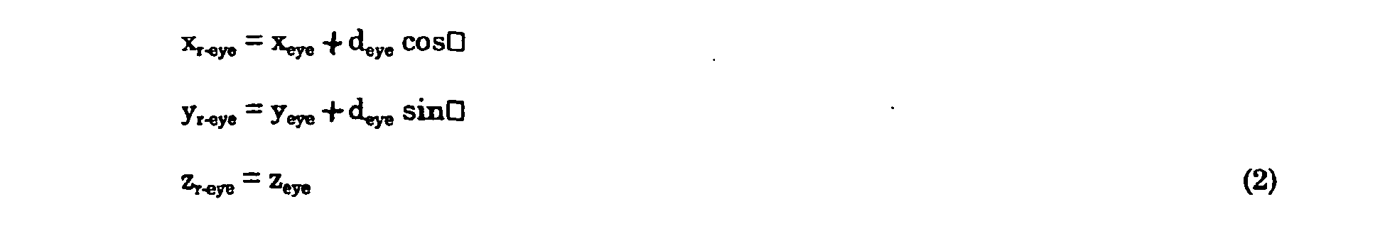
FIG 4 , how the position of both the left and right eye is calculated so as to perform three-dimensional display is described; where that position is derived, assuming the viewpoint position obtained using the positional sensor to be equal to the center of the eyes, based on the direction of the line of sight and the attitude angle derived from calculations. As shown inFIG 4 , the center position of the user's eyes and the distance from the center to both of the respective eyes, the rotational angle of the light of sight from the straight forward direction, along with the position of both respective eyes are defined as the following:
- When defined as in (1) above, the right and left viewpoint positions can be derived as the following equations (2):

- In this case, if the positional sensor is constructed integrated with glasses incorporating liquid crystal shutters, error is especially small, and it is possible to calculate the viewpoint position from the positional information obtained by the positional sensor, as described above.
- When movement of the viewpoint position is considered, it becomes necessary to set the position of the projection surface so that it is capable of handling the positional relationship of the viewpoint and the display surface. The method where the projection surface and the display surface are made to match can be used as a most basic method of appropriately setting the projection surface. With this method, in the case where the absolute position of the display surface within the real world is invariant, the absolute position of the projection surface within the virtual world is also invariant, there is no need to consider correction of the absolute position of the projection surface, and it becomes acceptable to consider only the relative position from the viewpoint.
- In addition, when the position of a virtual object assumed to exist lies on the other side of the viewpoint relative to the display surface in real space, in other words, in the case where the display surface is thought of as a window and one is peering into the virtual world through the window, the projection surface should be set to match the display surface in the simplistic manner described next.
- However, generally, in the system for rendering the virtual world, since the virtual world in front of the projection surface relative to the viewpoint is impossible to render, in cases where a virtual object exists on the side in front of the display surface relative to the user, it is not appropriate to set the projection surface to match the display surface.
- Therefore, with the system of this embodiment, as shown in
FIG 5(a) , assuming the rectangular area, which has four apexes that match each respective intersection of the four straight lines connecting each respective four nodes of adisplay surface 116 to the viewpoint and a plane at the rear of which thevirtual object 520 exists parallel to thedisplay surface 116 to be aprojection surface 510, the projected image is enlarged and displayed upon thedisplay surface 116 providing appropriate presentation of an image. It is noted that in the case where such a method is used, since the absolute position itself of theprojection surface 510 changes, it is necessary to derive the absolute position of theprojection surface 510 for every change in viewpoint position. -
FIG 5(b) shows an example of a display screen in the case where a relationship among the projection surface, the display surface, and the virtual object such as that shown inFIG 5(a) is assumed. If a relationship such as that shown inFIG 5(a) is assumed, that which is to be shown upon thedisplay surface 116 in the real world is an enlarged image. - In this manner, with the system of this embodiment, it is possible to freely set the relationship between the display surface and the projection surface. This makes it possible to display a virtual object by setting the projection surface without being limited to the actual display surface.
- A display region corresponding to the viewpoint position of the user is derived and image rendering is performed in that region. On this occasion, when the
hole 118 upondisplay mask 114 is circular, the display region corresponding to the position of the user viewpoint is also circular, and the position of the center thereof is determined in conformity with the following two parameters. - Position of the viewpoint upon the display coordinate system
- Distance between the mask and the display surface
- It is noted that with the system of this embodiment, the distance between the
mask 114 and thedisplay surface 116 is fixed. - The center of the
display surface 116 is made the origin, the coordinate system having the center ofdisplay surface 116 as the origin is set as shown inFIG 6 , with the viewpoint upon that coordinate system, the distance between the mask and the display surface, and the position of the center of the display region being defined as the following: - (xeye, yeye, zeye) : viewpoint position
- dmask-display distance between mask and display surface
- (xcenter, ycenter, zcenter) : center position of display region
- Based on the above-mentioned definitions, as shown in
FIG 7(a) , the center position of adisplay region 242 is derived from the following relational expression:
- In addition, as shown in
FIG 7(b) the radius defining the magnitude of thecircular display region 242, is derived from the following three parameters: - distance of the viewpoint from the display surface
- distance between the mask and the display surface
- radius of the hole upon the mask
- Here the radius of the
hole 118 upon themask 114 and the radius of thedisplay region 242 are respectively defined as the following: - rhole : radius of the hole on the mask
- rdraw : radius of the display region
- In this case, the radius rdraw of the display region is represented by the following:

- By performing processing of the display region in the above manner, it is possible to perform display of an image for every user in the
display region 242 that is dynamically derived in accordance with the position of the respective user. - Since there is a plurality of users, it is necessary to perform an overlapping search among regions derived in conformity with the processing described above. In the case where the display region is circular, detection of an overlapping region can be performed through the relationship of the distance between centers and the sum of the radiuses. With a system of this embodiment, when overlapping is detected, the users can be alerted to an overlapping display region through, for example, the rendering of a demarcation line for the display region.
- With the system of this embodiment, for example, the display has a rectangular shape with a width of 1360 mm and height of 1020 mm, and from the surface of the floor the height of the display surface is 1000 mm. The distance between the display mask and the display surface is 150 mm and the radius of the mask hole is 200 mm.
- The system of the embodiment described above is an example where the display surface is placed horizontally; alternatively, the display surface may naturally be placed vertically or at a slant. If the display is made to be the projection type, it is possible to achieve a large screen display. In addition, in order to configure a large display, a plurality of displays may be combined.
-
FIG 8 shows a theatre-style multi-person shared three-dimensional display device capable of being used by multiple persons. With the theatre style multi-person shared three-dimensional display device, for example, given a width of 25 m, height of 18 m, distance of 6 m between the display mask and the display surface, radius of 0.5 m for the mask hole of the display mask, a maximum of forty-eight persons can simultaneously view the respective videos. - It is not necessary to make the hole upon the display mask circular; for example, a rectangular shape is also allowable.
- If the display mask is configured with liquid crystal, it is possible to control the radius, shape, and location of the hole of the display mask through the permeability and non-permeability of the liquid crystal.
- In addition, in order to control the radius, etc. of the hole of the display mask, for example, a mechanical mechanism such as an aperture mechanism or the like can be used.
- With the multi-person shared three-dimensional display apparatus described above, glasses with attached shutters are utilized wherein the opening and closing of the shutters is synchronized and images corresponding to the left/right line of sight are displayed to obtain a three-dimensional image; however, the present invention is not limited to this method for obtaining a three-dimensional view. For example, a filter based on polarization or color may be used as the glasses to be worn to segregate images corresponding to the left and right lines of sight.
- In addition, as an example of three-dimensional display not using glasses, there is the display device mentioned in, for example, Japanese Patent Application Laid-open No.
2001-13457 - It is possible to use these multi-person shared three-dimensional display devices, for example, for entertainment purposes. A configuration example corresponding to such entertainment purposes is shown in
FIG 9 . InFIG 9(a) , audience members traveling aboardcarts display 416 via ahole 418 indisplay mask 414.FIG 9(b) shows a configuration where a three-dimensional image displayed on adisplay 516 is viewed through ahole 518 in adisplay mask 514 while a plurality of audience members are moving about a central stage. - When the fact that display on a display surface is possible by separating images for every person with a display hole is utilized, not only images for three-dimensional viewing, but also display of different information for each person is possible. An example of this configuration is shown in
FIG 10 . This configuration, as shown inFIG 10 , is a fundamentally similar configuration as the multi-person shared three-dimensional display device shown inFIG 1 . With this configuration,sensors processing device 130. Theprocessing device 130, in conformity with the detected positions, performs display corresponding to each person on thedisplay regions - With the multi-person shared display device of the present invention, it is possible to perform appropriate display corresponding to viewpoint movement for a plurality of persons.
- With this multi-person shared display device, the relative positions between the viewpoint and projection surface in the virtual world are appropriately corrected corresponding to changes in the relative positions between the viewpoint and projection surface in the real world. Moreover, with the present invention, for example with a single fixed display, a three-dimensional image can be displayed for a plurality of moving users having neither flickering nor spatial distortion. In addition, regions of viewpoint movement allowing a user to obtain an appropriate image have also been described in detail.
- The present invention is applicable to not only a stand-alone computer system, but may also be made applicable to, for example, a client server system or the like configured from a plurality of systems.
- It is possible to provide a configuration of the present invention by having a system read out a program relating to the present invention from storage media stored with the program and execute it. Such storage media includes floppy disks, CD-ROMS, magnetic tape, and ROM cassettes.
- With the display device of the present invention, an image rendered upon a screen in compliance with the individual audience member positions is viewed via a hole of an appropriate size an appropriate distance from the screen. As a result, it is possible to view video in compliance with the individual viewpoint positions of a plurality of persons.
- Technology relating to such a multi-person shared display device is capable of wide range industrial applicability, for example as a device for viewing three-dimensional objects.
Claims (5)
- A multi-person shared display device (110), which is a display device suitable to be shared by a plurality of users, comprising:a display device (112), which displays a plurality of images for a plurality of users (140, 150) on a common display surface (116);a display mask (114), which is disposed so as to cover said display surface (116) and which is separated from said display surface (116) by a fixed distance and has a hole (118) so that the display mask (114) hides portions beside the hole (118);a viewpoint position detecting sensor (144, 154) which detects a viewpoint position of a user (140, 150) in real space relative to said display device (112); anda processing device (130) which is dynamically combined with said one display device (112) and said viewpoint position detecting sensor (144, 154) and which renders an image corresponding to each user's (140, 150) viewpoint position and displays the image on the user's (140, 150) corresponding display region (242) of said display surface (116) in accordance with said viewpoint position of the user (140, 150) that has been detected by said viewpoint position detecting sensor (144, 154),characterized in that
the hole (118) provided in the display mask (114) is the only portion through which the display surface (116) of the display device (112) can be seen, whereby the viewable display region (242) on the display surface (116) varies depending on the viewpoint position of the user (140, 150),
the processing device (130) derives the display region (242) corresponding to the viewpoint of the user (140, 150) and performs image rendering for that region, and
the hole (118) is sufficiently large to enable each user (140, 150) to entirely see that user's (140, 150) corresponding display region (242) on the display surface (116). - The multi-person shared display device (110) according to Claim 1, wherein said image to be displayed upon the display surface (116) includes video for three-dimensional viewing.
- The multi-person shared display device (110) according to Claim 2, wherein
each user (140, 150) wears glasses (142, 152) for separating said video for three-dimensional viewing displayed upon the display surface (116) into that for the right eye and that for the left eye; and
the plurality of video for three dimensional viewing shown on said display surface (116) are images allowing separation between that for the right eye and that for the left eye through said glasses (142, 152). - The multi-person shared display device (110) according to Claim 3, wherein
said glasses (142, 152) are glasses in which shutters for the right eye and for the left eye open and close; and
said processing device (130) is dynamically combined with said glasses (142, 152). - The multi-person shared display device (110) according to either Claim 3 or Claim 4, wherein said glasses (142, 152) and said viewpoint position detecting sensor (144, 154) are formed as an integral unit.
Applications Claiming Priority (3)
| Application Number | Priority Date | Filing Date | Title |
|---|---|---|---|
| JP2000199240 | 2000-06-30 | ||
| JP2000199240 | 2000-06-30 | ||
| PCT/JP2001/005656 WO2002003124A1 (en) | 2000-06-30 | 2001-06-29 | Multiple sharing type display device |
Publications (3)
| Publication Number | Publication Date |
|---|---|
| EP1296173A1 EP1296173A1 (en) | 2003-03-26 |
| EP1296173A4 EP1296173A4 (en) | 2008-04-09 |
| EP1296173B1 true EP1296173B1 (en) | 2012-06-13 |
Family
ID=18697290
Family Applications (1)
| Application Number | Title | Priority Date | Filing Date |
|---|---|---|---|
| EP01945723A Expired - Lifetime EP1296173B1 (en) | 2000-06-30 | 2001-06-29 | Multiple sharing type display device |
Country Status (4)
| Country | Link |
|---|---|
| US (1) | US6965381B2 (en) |
| EP (1) | EP1296173B1 (en) |
| JP (1) | JP4616543B2 (en) |
| WO (1) | WO2002003124A1 (en) |
Families Citing this family (34)
| Publication number | Priority date | Publication date | Assignee | Title |
|---|---|---|---|---|
| US7070921B2 (en) | 2000-04-28 | 2006-07-04 | Molecular Devices Corporation | Molecular modification assays |
| JP2004364197A (en) * | 2003-06-06 | 2004-12-24 | Asahi Kasei Electronics Co Ltd | Sensor unit |
| US7538746B2 (en) * | 2004-07-23 | 2009-05-26 | Lockheed Martin Corporation | Direct ocular virtual 3D workspace |
| JP4664108B2 (en) * | 2005-03-31 | 2011-04-06 | 富士通株式会社 | Display device, display method, display program, and display system |
| WO2007117485A2 (en) * | 2006-04-03 | 2007-10-18 | Sony Computer Entertainment Inc. | Screen sharing method and apparatus |
| WO2008152183A1 (en) * | 2007-06-15 | 2008-12-18 | Fogscreen Inc. | Display screen based on particles carried in a fluid stream |
| GB0920754D0 (en) * | 2009-11-27 | 2010-01-13 | Compurants Ltd | Inamo big book 1 |
| US20110141246A1 (en) * | 2009-12-15 | 2011-06-16 | Justin Michael Schwartz | System and Method for Producing Stereoscopic Images |
| KR101313797B1 (en) * | 2009-12-18 | 2013-10-01 | 한국전자통신연구원 | Apparatus and method for presenting display of 3D image using head tracking |
| DE102010009737A1 (en) * | 2010-03-01 | 2011-09-01 | Institut für Rundfunktechnik GmbH | Method and arrangement for reproducing 3D image content |
| US9030536B2 (en) | 2010-06-04 | 2015-05-12 | At&T Intellectual Property I, Lp | Apparatus and method for presenting media content |
| US8593574B2 (en) | 2010-06-30 | 2013-11-26 | At&T Intellectual Property I, L.P. | Apparatus and method for providing dimensional media content based on detected display capability |
| US8640182B2 (en) | 2010-06-30 | 2014-01-28 | At&T Intellectual Property I, L.P. | Method for detecting a viewing apparatus |
| US9787974B2 (en) | 2010-06-30 | 2017-10-10 | At&T Intellectual Property I, L.P. | Method and apparatus for delivering media content |
| US8918831B2 (en) | 2010-07-06 | 2014-12-23 | At&T Intellectual Property I, Lp | Method and apparatus for managing a presentation of media content |
| US9049426B2 (en) | 2010-07-07 | 2015-06-02 | At&T Intellectual Property I, Lp | Apparatus and method for distributing three dimensional media content |
| US9232274B2 (en) | 2010-07-20 | 2016-01-05 | At&T Intellectual Property I, L.P. | Apparatus for adapting a presentation of media content to a requesting device |
| US9560406B2 (en) | 2010-07-20 | 2017-01-31 | At&T Intellectual Property I, L.P. | Method and apparatus for adapting a presentation of media content |
| US9032470B2 (en) | 2010-07-20 | 2015-05-12 | At&T Intellectual Property I, Lp | Apparatus for adapting a presentation of media content according to a position of a viewing apparatus |
| US8994716B2 (en) | 2010-08-02 | 2015-03-31 | At&T Intellectual Property I, Lp | Apparatus and method for providing media content |
| US8438502B2 (en) | 2010-08-25 | 2013-05-07 | At&T Intellectual Property I, L.P. | Apparatus for controlling three-dimensional images |
| US8947511B2 (en) | 2010-10-01 | 2015-02-03 | At&T Intellectual Property I, L.P. | Apparatus and method for presenting three-dimensional media content |
| US8619124B2 (en) * | 2010-10-14 | 2013-12-31 | Industrial Technology Research Institute | Video data processing systems and methods |
| US9030522B2 (en) | 2011-06-24 | 2015-05-12 | At&T Intellectual Property I, Lp | Apparatus and method for providing media content |
| US9445046B2 (en) | 2011-06-24 | 2016-09-13 | At&T Intellectual Property I, L.P. | Apparatus and method for presenting media content with telepresence |
| US8947497B2 (en) | 2011-06-24 | 2015-02-03 | At&T Intellectual Property I, Lp | Apparatus and method for managing telepresence sessions |
| US9602766B2 (en) | 2011-06-24 | 2017-03-21 | At&T Intellectual Property I, L.P. | Apparatus and method for presenting three dimensional objects with telepresence |
| US8587635B2 (en) | 2011-07-15 | 2013-11-19 | At&T Intellectual Property I, L.P. | Apparatus and method for providing media services with telepresence |
| KR20130075253A (en) * | 2011-12-27 | 2013-07-05 | 한국전자통신연구원 | Method and apparatus for displaying stereoscopic image contents using pixel mapping |
| KR102153743B1 (en) | 2013-11-01 | 2020-09-10 | 삼성디스플레이 주식회사 | Display device |
| US9712810B2 (en) * | 2015-06-03 | 2017-07-18 | Disney Enterprises, Inc. | Tracked automultiscopic 3D tabletop display |
| DE102017208936A1 (en) * | 2017-05-29 | 2018-11-29 | Audi Ag | Method for operating a virtual reality system and virtual reality system |
| US10922892B1 (en) * | 2019-04-30 | 2021-02-16 | Splunk Inc. | Manipulation of virtual object position within a plane of an extended reality environment |
| CN117939106B (en) * | 2024-03-19 | 2024-05-24 | 成都工业学院 | A viewpoint planning component for stereoscopic display |
Family Cites Families (12)
| Publication number | Priority date | Publication date | Assignee | Title |
|---|---|---|---|---|
| US5521724A (en) * | 1993-11-15 | 1996-05-28 | Shires; Mark R. | Real-time automultiscopic 3D video display using holographic optical elements (HOEs) |
| JP3516774B2 (en) | 1995-06-14 | 2004-04-05 | 三菱電機株式会社 | 3D image display device |
| JP2846856B2 (en) | 1996-07-19 | 1999-01-13 | 三洋電機株式会社 | 3D image display device |
| JP3472068B2 (en) * | 1997-03-19 | 2003-12-02 | 株式会社国際電気通信基礎技術研究所 | 3D image display device |
| JP2001519126A (en) * | 1997-03-27 | 2001-10-16 | リットン・システムズ・インコーポレーテッド | Automatic stereoscopic projection system |
| US5993003A (en) * | 1997-03-27 | 1999-11-30 | Litton Systems, Inc. | Autostereo projection system |
| US6798390B1 (en) * | 1997-08-29 | 2004-09-28 | Canon Kabushiki Kaisha | 3D image reconstructing apparatus and 3D object inputting apparatus |
| JP3403048B2 (en) | 1997-12-10 | 2003-05-06 | キヤノン株式会社 | Three-dimensional image reproducing device and three-dimensional subject information input device |
| DE19746764B4 (en) * | 1997-10-23 | 2006-09-14 | Siemens Ag | display unit |
| US6710920B1 (en) * | 1998-03-27 | 2004-03-23 | Sanyo Electric Co., Ltd | Stereoscopic display |
| US5926318A (en) * | 1998-04-06 | 1999-07-20 | Optimize Incorporated | Biocular viewing system with intermediate image planes for an electronic display device |
| WO2001038918A1 (en) * | 1999-11-22 | 2001-05-31 | Sl3D, Inc. | Stereoscopic telescope with camera |
-
2001
- 2001-06-29 EP EP01945723A patent/EP1296173B1/en not_active Expired - Lifetime
- 2001-06-29 JP JP2002508131A patent/JP4616543B2/en not_active Expired - Fee Related
- 2001-06-29 US US10/069,718 patent/US6965381B2/en not_active Expired - Lifetime
- 2001-06-29 WO PCT/JP2001/005656 patent/WO2002003124A1/en not_active Ceased
Also Published As
| Publication number | Publication date |
|---|---|
| EP1296173A1 (en) | 2003-03-26 |
| JP4616543B2 (en) | 2011-01-19 |
| WO2002003124A1 (en) | 2002-01-10 |
| US6965381B2 (en) | 2005-11-15 |
| US20030043146A1 (en) | 2003-03-06 |
| EP1296173A4 (en) | 2008-04-09 |
Similar Documents
| Publication | Publication Date | Title |
|---|---|---|
| EP1296173B1 (en) | Multiple sharing type display device | |
| Kulik et al. | C1x6: a stereoscopic six-user display for co-located collaboration in shared virtual environments | |
| EP0751689B1 (en) | Stereoscopic image generating apparatus and display therefor | |
| JPWO2002003124A1 (en) | Multi-person display device | |
| US5742331A (en) | Three-dimensional image display apparatus | |
| US8179424B2 (en) | 3D display method and apparatus | |
| EP0862767B1 (en) | Three-dimensional drawing system and method | |
| US6788274B2 (en) | Apparatus and method for displaying stereoscopic images | |
| US6239830B1 (en) | Displayer and method for displaying | |
| JP4052357B2 (en) | Virtual environment experience display device | |
| JPH09238369A (en) | 3D image display device | |
| JP2000310826A (en) | Virtual environmental experience display device | |
| US6061084A (en) | Displayer and a method for displaying | |
| WO2021106379A1 (en) | Image processing device, image processing method, and image display system | |
| Baker | Generating images for a time-multiplexed stereoscopic computer graphics system | |
| US20130155502A1 (en) | Autostereoscopic 3-dimensional (3d) display apparatus and display method thereof | |
| JP3425402B2 (en) | Apparatus and method for displaying stereoscopic image | |
| JP2007323093A (en) | Display device for virtual environment experience | |
| US20040178969A1 (en) | Spatial three-dimensional image display device | |
| JP3088326B2 (en) | 3D image display device | |
| Kang Wei et al. | Three-dimensional scene navigation through anaglyphic panorama visualization | |
| Lipton | Future of autostereoscopic electronic displays | |
| Reinhart | Effects of depth cues on depth judgements using a field-sequential stereoscopic CRT display | |
| US10701345B2 (en) | System and method for generating a stereo pair of images of virtual objects | |
| Lacoche et al. | Dealing with frame cancellation for stereoscopic displays in 3d user interfaces |
Legal Events
| Date | Code | Title | Description |
|---|---|---|---|
| PUAI | Public reference made under article 153(3) epc to a published international application that has entered the european phase |
Free format text: ORIGINAL CODE: 0009012 |
|
| 17P | Request for examination filed |
Effective date: 20020322 |
|
| AK | Designated contracting states |
Kind code of ref document: A1 Designated state(s): AT BE CH CY DE DK ES FI FR GB GR IE IT LI LU MC NL PT SE TR |
|
| RBV | Designated contracting states (corrected) |
Designated state(s): BE DE FR GB |
|
| A4 | Supplementary search report drawn up and despatched |
Effective date: 20080307 |
|
| 17Q | First examination report despatched |
Effective date: 20080912 |
|
| REG | Reference to a national code |
Ref country code: DE Ref legal event code: R079 Ref document number: 60146704 Country of ref document: DE Free format text: PREVIOUS MAIN CLASS: G02B0027220000 Ipc: G06F0003010000 |
|
| GRAP | Despatch of communication of intention to grant a patent |
Free format text: ORIGINAL CODE: EPIDOSNIGR1 |
|
| RIC1 | Information provided on ipc code assigned before grant |
Ipc: H04N 13/04 20060101ALI20111202BHEP Ipc: G06F 3/01 20060101AFI20111202BHEP |
|
| GRAS | Grant fee paid |
Free format text: ORIGINAL CODE: EPIDOSNIGR3 |
|
| GRAA | (expected) grant |
Free format text: ORIGINAL CODE: 0009210 |
|
| AK | Designated contracting states |
Kind code of ref document: B1 Designated state(s): BE DE FR GB |
|
| REG | Reference to a national code |
Ref country code: GB Ref legal event code: FG4D |
|
| REG | Reference to a national code |
Ref country code: DE Ref legal event code: R096 Ref document number: 60146704 Country of ref document: DE Effective date: 20120809 |
|
| PLBE | No opposition filed within time limit |
Free format text: ORIGINAL CODE: 0009261 |
|
| STAA | Information on the status of an ep patent application or granted ep patent |
Free format text: STATUS: NO OPPOSITION FILED WITHIN TIME LIMIT |
|
| 26N | No opposition filed |
Effective date: 20130314 |
|
| REG | Reference to a national code |
Ref country code: DE Ref legal event code: R097 Ref document number: 60146704 Country of ref document: DE Effective date: 20130314 |
|
| REG | Reference to a national code |
Ref country code: FR Ref legal event code: PLFP Year of fee payment: 16 |
|
| REG | Reference to a national code |
Ref country code: FR Ref legal event code: PLFP Year of fee payment: 17 |
|
| REG | Reference to a national code |
Ref country code: FR Ref legal event code: PLFP Year of fee payment: 18 |
|
| PGFP | Annual fee paid to national office [announced via postgrant information from national office to epo] |
Ref country code: DE Payment date: 20180625 Year of fee payment: 18 |
|
| PGFP | Annual fee paid to national office [announced via postgrant information from national office to epo] |
Ref country code: FR Payment date: 20180620 Year of fee payment: 18 Ref country code: BE Payment date: 20180620 Year of fee payment: 18 |
|
| PGFP | Annual fee paid to national office [announced via postgrant information from national office to epo] |
Ref country code: GB Payment date: 20180620 Year of fee payment: 18 |
|
| REG | Reference to a national code |
Ref country code: DE Ref legal event code: R119 Ref document number: 60146704 Country of ref document: DE |
|
| GBPC | Gb: european patent ceased through non-payment of renewal fee |
Effective date: 20190629 |
|
| REG | Reference to a national code |
Ref country code: BE Ref legal event code: MM Effective date: 20190630 |
|
| PG25 | Lapsed in a contracting state [announced via postgrant information from national office to epo] |
Ref country code: DE Free format text: LAPSE BECAUSE OF NON-PAYMENT OF DUE FEES Effective date: 20200101 Ref country code: GB Free format text: LAPSE BECAUSE OF NON-PAYMENT OF DUE FEES Effective date: 20190629 |
|
| PG25 | Lapsed in a contracting state [announced via postgrant information from national office to epo] |
Ref country code: BE Free format text: LAPSE BECAUSE OF NON-PAYMENT OF DUE FEES Effective date: 20190630 |
|
| PG25 | Lapsed in a contracting state [announced via postgrant information from national office to epo] |
Ref country code: FR Free format text: LAPSE BECAUSE OF NON-PAYMENT OF DUE FEES Effective date: 20190630 |