EP1252443B1 - Hydraulic fluid vane pump - Google Patents
Hydraulic fluid vane pump Download PDFInfo
- Publication number
- EP1252443B1 EP1252443B1 EP01902091A EP01902091A EP1252443B1 EP 1252443 B1 EP1252443 B1 EP 1252443B1 EP 01902091 A EP01902091 A EP 01902091A EP 01902091 A EP01902091 A EP 01902091A EP 1252443 B1 EP1252443 B1 EP 1252443B1
- Authority
- EP
- European Patent Office
- Prior art keywords
- pump
- fluid
- discharge passageway
- discharge
- hydraulic fluid
- Prior art date
- Legal status (The legal status is an assumption and is not a legal conclusion. Google has not performed a legal analysis and makes no representation as to the accuracy of the status listed.)
- Expired - Lifetime
Links
Images


Classifications
-
- F—MECHANICAL ENGINEERING; LIGHTING; HEATING; WEAPONS; BLASTING
- F04—POSITIVE - DISPLACEMENT MACHINES FOR LIQUIDS; PUMPS FOR LIQUIDS OR ELASTIC FLUIDS
- F04C—ROTARY-PISTON, OR OSCILLATING-PISTON, POSITIVE-DISPLACEMENT MACHINES FOR LIQUIDS; ROTARY-PISTON, OR OSCILLATING-PISTON, POSITIVE-DISPLACEMENT PUMPS
- F04C14/00—Control of, monitoring of, or safety arrangements for, machines, pumps or pumping installations
- F04C14/24—Control of, monitoring of, or safety arrangements for, machines, pumps or pumping installations characterised by using valves controlling pressure or flow rate, e.g. discharge valves or unloading valves
- F04C14/26—Control of, monitoring of, or safety arrangements for, machines, pumps or pumping installations characterised by using valves controlling pressure or flow rate, e.g. discharge valves or unloading valves using bypass channels
-
- F—MECHANICAL ENGINEERING; LIGHTING; HEATING; WEAPONS; BLASTING
- F04—POSITIVE - DISPLACEMENT MACHINES FOR LIQUIDS; PUMPS FOR LIQUIDS OR ELASTIC FLUIDS
- F04C—ROTARY-PISTON, OR OSCILLATING-PISTON, POSITIVE-DISPLACEMENT MACHINES FOR LIQUIDS; ROTARY-PISTON, OR OSCILLATING-PISTON, POSITIVE-DISPLACEMENT PUMPS
- F04C11/00—Combinations of two or more machines or pumps, each being of rotary-piston or oscillating-piston type; Pumping installations
- F04C11/001—Combinations of two or more machines or pumps, each being of rotary-piston or oscillating-piston type; Pumping installations of similar working principle
-
- F—MECHANICAL ENGINEERING; LIGHTING; HEATING; WEAPONS; BLASTING
- F04—POSITIVE - DISPLACEMENT MACHINES FOR LIQUIDS; PUMPS FOR LIQUIDS OR ELASTIC FLUIDS
- F04C—ROTARY-PISTON, OR OSCILLATING-PISTON, POSITIVE-DISPLACEMENT MACHINES FOR LIQUIDS; ROTARY-PISTON, OR OSCILLATING-PISTON, POSITIVE-DISPLACEMENT PUMPS
- F04C14/00—Control of, monitoring of, or safety arrangements for, machines, pumps or pumping installations
- F04C14/06—Control of, monitoring of, or safety arrangements for, machines, pumps or pumping installations specially adapted for stopping, starting, idling or no-load operation
-
- F—MECHANICAL ENGINEERING; LIGHTING; HEATING; WEAPONS; BLASTING
- F04—POSITIVE - DISPLACEMENT MACHINES FOR LIQUIDS; PUMPS FOR LIQUIDS OR ELASTIC FLUIDS
- F04C—ROTARY-PISTON, OR OSCILLATING-PISTON, POSITIVE-DISPLACEMENT MACHINES FOR LIQUIDS; ROTARY-PISTON, OR OSCILLATING-PISTON, POSITIVE-DISPLACEMENT PUMPS
- F04C2/00—Rotary-piston machines or pumps
- F04C2/30—Rotary-piston machines or pumps having the characteristics covered by two or more groups F04C2/02, F04C2/08, F04C2/22, F04C2/24 or having the characteristics covered by one of these groups together with some other type of movement between co-operating members
- F04C2/34—Rotary-piston machines or pumps having the characteristics covered by two or more groups F04C2/02, F04C2/08, F04C2/22, F04C2/24 or having the characteristics covered by one of these groups together with some other type of movement between co-operating members having the movement defined in groups F04C2/08 or F04C2/22 and relative reciprocation between the co-operating members
- F04C2/344—Rotary-piston machines or pumps having the characteristics covered by two or more groups F04C2/02, F04C2/08, F04C2/22, F04C2/24 or having the characteristics covered by one of these groups together with some other type of movement between co-operating members having the movement defined in groups F04C2/08 or F04C2/22 and relative reciprocation between the co-operating members with vanes reciprocating with respect to the inner member
- F04C2/3446—Rotary-piston machines or pumps having the characteristics covered by two or more groups F04C2/02, F04C2/08, F04C2/22, F04C2/24 or having the characteristics covered by one of these groups together with some other type of movement between co-operating members having the movement defined in groups F04C2/08 or F04C2/22 and relative reciprocation between the co-operating members with vanes reciprocating with respect to the inner member the inner and outer member being in contact along more than one line or surface
Definitions
- the present invention relates generally to hydraulic pumps audio particular to a hydraulic fluid pump as defined in the preamble of claim 1.
- a hydraulic fluid pump as defined in the preamble of claim 1.
- Such a pump is known eg from any of EP-A-0522505 , JP-61125966 , US-A-4599051 or US-A-5609474 .
- a fluid powered system e.g., steering system or transmission system
- the hydraulic pump creates the hydraulic force and typically a flow control valve regulates the flow.
- a conventional vane-type pump comprises a cam (pump) ring having a substantially elliptical cam surface, a rotor which is adapted to rotate within the cam ring and a plurality of vanes adapted to move back and forth within radial slits formed in the rotor.
- the cam ring is stationary and the outer edges of the vanes touch the inside of the surface of the cam ring.
- each pumping cavity constantly changes due to the elliptically shaped cam ring. Volume increases as the vanes move through the rising portion of the cam ring, drawing fluid through an intake port. When the vanes move into the "falling" portion of the ring contour, volume decreases. Decreased volume increases pressure, forcing fluid out through the discharge port.
- An intake portion of the hydraulic pump receives low-pressure hydraulic fluid from a pump reservoir. Discharged fluid, under high pressure, flows to a desired system location (e.g., a steering gear to provide power assist).
- the operating system can handle the volume of hydraulic fluid provided by the pump. Flow dramatically increased at higher speeds because the pump draws and discharges a greater volume of fluid.
- the volume of the discharged fluid exceeds the demand of the system but due to the design of the pump, the pump is required to direct all the fluid from the pump and throughout the system. These conditions raise operating temperatures and reduce pump durability.
- the torque necessary to drive the pump increases at higher system back pressures which corresponds to additional horsepower (energy) being required to effectively overcome the system back pressure and distribute the fluid throughout the system.
- variable displacement pump Another pump conventionally used is a variable displacement pump.
- a variable displacement pump provides a reduction in flow as a function of operating conditions and therefore requires more costly shaft support solutions. Additionally, since variable displacement pumps are typically single stroke, the pumps require a larger package size to provide the same pumping capacity. Variable displacement pump valving also make these pumps less efficient in the full displacement operating condition.
- a hydraulic fluid pump for use with a fluid powered system as claimed in claim 1.
- the fixed displacement pump comprises a vane-type pump having a vane assembly which includes pumping cavities formed by a plurality of vanes. The constantly changing volume of these pumping cavities as the pump is driven causes fluid to be both drawn into the pumping cavities and forced out of the pumping cavities and through discharge ports of the pump.
- a pair of discharge ports are provided, namely a first discharge port and a second discharge port.
- the first discharge port fluidly communicates with a primary discharge passageway and discharge outlet which is connected to a primary line for distributing the fluid throughout the system.
- the second discharge port fluidly communicates with a secondary discharge passageway which is in selective fluid communication with a low pressure line connected to a low pressure area of the pump (e.g., a reservoir) under first operating conditions and is also in selective communication with the first discharge port and the primary discharge passageway under second operating conditions.
- the first operating conditions comprise high speed operating conditions (e.g., pump speeds above 2500 rpm) where pump output exceeds system fluid demands and the second operating conditions comprise low speed operating conditions where system demands require full pump capacity.
- a flow control valve is disposed within the pump and acts to direct the fluid flowing within the secondary discharge passageway according to either a second discharge path, wherein the fluid is directed to the low pressure line and the low pressure reservoir or sump of the system, or a third discharge path, wherein the fluid is directed to the primary discharge passage and is subjected to the high pressure line of the system.
- the flow control valve comprises a hydro-mechanically controlled valve which is designed to actuate when the fluid flowing within the secondary discharge passageway reaches a predetermined flow rate. Upon actuation, all of the fluid flowing through the secondary discharge passageway is directed to the low pressure line instead of the high pressure line of the primary discharge passageway. As a result, only fluid flowing in the primary discharge passageway is exposed to the high pressure of the system line and the fluid within the secondary passageway is subjected to a much lower pressure in the low pressure line.
- the pump preferably further includes a check valve which is placed between the primary and secondary discharge passageways to control backflow from the primary discharge passageway when the secondary discharge passageway is exposed to low pressure.
- the flow control valve is actuated under high pump speed operating conditions (e.g., above 2500 rpm) where the pump output significantly exceeds system demands.
- high pump speed operating conditions e.g., above 2500 rpm
- the flow control valve is not actuated and all of the fluid within the secondary discharge passageway is directed to the primary discharge passageway and is exposed to the high pressure line of the system so that the system demands are satisfied.
- FIG. 1 is a cross sectional view of a typical conventional vane-type pump showing the discharge ports and fluid flow paths of the pump.
- the vane-type pump is generally indicated at 10 and comprises a pump having dual internal discharge ports.
- the vanes within the rotor and the cam ring (all not shown) define pumping cavities. More specifically, the space between the rotor, ring and any two adjacent vanes defines a single pumping cavity. The rotation of the rotor and movement of the vanes causes the volume of each pumping cavity to constantly change due to the shape of the cam ring which is typically oval-shaped (elliptical).
- each pumping cavity increases resulting in the fluid being drawn through an intake port of the pump.
- the vane assembly is driven by a drive shaft 11.
- the volume of each pumping cavity decreases. Decreased volume within the pumping cavity causes an increase in pressure within each pumping cavity resulting in the fluid being forced out of the pumping cavity and through the discharge ports of the pump 10.
- the illustrated vane-type pump 10 shown in Figure 1 includes a first discharge port 12 and a second discharge port 14.
- first and second discharge ports 12 and 14 are routed to a common discharge outlet generally indicated at 16.
- first and second discharge ports 12 and 14 join at a common discharge outlet 16 as the fluid is pumped to a desired system location.
- the fluid flow path from the first and second discharge ports 12 and 14 is generally indicated by directional arrows 18.
- pump 10 is required to force the fluid through the common discharge outlet 16 and the fluid works against system back pressure.
- pump 10 Because of the back pressure which is observed in the system, in order for pump 10 to effectively distribute the fluid through the overall system, pump 10 must force the fluid at such a flow rate that the fluid overcomes the back pressure of the system and is therefore effectively distributed throughout the system. In this type of pump design, the fluid passing through both the first and second discharge ports 12 and 14 must work against the system back pressure.
- the operating system in which pump 10 is being used requires a certain fluid flow rate so that a sufficient amount of fluid is pumped throughout the system for proper operation thereof and in this design, pump 10 distributes all the fluid throughout the system.
- the energy consumption of the pump is linked to the amount of torque required to drive the unit and as the torque increases, an increase in horsepower is likewise observed and energy consumption rises.
- a dual port hydraulic fixed displacement pump is made more efficient by limiting the volume of the discharged fluid, e.g. oil, which is subjected to the line pressure of the hydraulic system.
- the present invention may be incorporated into a number of types of pumping assemblies, including piston pumps, vane-type pumps and gear pumps; however, for the purpose of illustration only, the present invention is described with reference to an exemplary dual port hydraulic fixed displacement vane-type pump. It being understood that one of skill would appreciate that the improved efficiency dual discharge port design of the present invention may be incorporated into these other pump assemblies besides the illustrated vane-type pump.
- the exemplary vane-type pump is generally indicated at 20 in Figure 2 .
- the term "fixed displacement pump” refers to a pump in which an increase in the speed of the pump leads to a corresponding increase in the flow rate of the discharged fluid.
- Vane-type pump 20 includes a pump housing 22 having an internal housing cavity 24 with a large opening 26 at one end thereof and a smaller opening 28 at the other end thereof.
- a drive shaft 30 extends through the smaller opening 28 and is rotatably supported in a shaft bearing 51 which is secured in the opening 28 and is contacted by a shaft seal 32 also secured within the opening 28.
- Adequate shaft support is placed in the assembly to deal with bending loads which result from the unbalanced condition when pump 20 is operating in a fuel efficient mode.
- the shaft seal 32 functions to prevent atmospheric air from entering the pump 20 and low pressure fluid leakage from pump 20.
- the housing cavity 24 is substantially filled with a vane pump assembly, generally designated at 40, and includes a pressure plate 42, a cam ring 44. a rotor 46, a plurality of vanes (not shown), and an end cover 49 and thrust plate 50.
- the end cover 49 cooperates with annular seal ring 52 and a locking ring 54 to close the large opening 26.
- the rotor 46 includes a plurality of slots in which the plurality of vanes are slidably disposed as is known in the art.
- the plurality of vanes contact the inner surface of cam ring 44 so as to provide a plurality of peripheral pumping chambers 60 which expand and contract upon the rotation of rotor 46 when it is driven by a drive shaft 30.
- the thrust plate 50 includes discharge porting arrangements as will be described in greater detail hereinafter to effectively direct the forced fluid from vane assembly 40 to discharge passageways and outlets of the pump 20 which act to distribute the fluid to the other components of the system.
- the discharged fluid from the pumping chambers 60 of the vane assembly 40 passes through the thrust plate 50 to first and second discharge ports 80 and 82, respectively, which in turn are in fluid communication with a pump discharge passage (not shown in Figure 2 ) formed in pump 20.
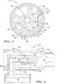
- Figure 3 illustrates the dual fluid discharge port design of the pump 20.
- First discharge port 80 fluidly communicates with a discharge outlet 86 which serves to route the discharged fluid within a system line to components of the system, whether it be gear assemblies in a power steering system or transmission components in a transmission assembly.
- the first discharge port 80 is part of a primary discharge passageway 90 for the fluid to flow in response to the pumping action.
- a primary discharge path in which the fluid flows from first discharge port 80 is illustrated by directional arrows 92.
- this primary discharge passageway 90 is exposed to working line pressure of the system under all operating conditions of the pump. In other words, at either low speed or high speed operating conditions, pump 20 must work against the line pressure of the system in order to effectively distribute fluid according to the primary discharge path 92 as the fluid is distributed throughout the system.
- second discharge port 82 partially defines a second discharge path for the fluid to flow in response to the action of pump 20.
- second discharge port 82 fluidly communicates with a secondary discharge passageway 110 so that fluid flowing through second discharge port 82 is directed to secondary discharge passageway 110.
- Secondary discharge passageway 110 has a first portion 112 and a second portion 114, wherein second portion 114 is in selective fluid communication with first discharge port 80 and permits the discharged fluid within secondary discharge passageway 110 to join the fluid flowing through first discharge port 80 under selective operating conditions, as will be described in greater detail hereinafter.
- Secondary discharge passageway 110 includes a flow control valve 120 which is generally disposed between first and second portions 112 and 114 thereof.
- Flow control valve 120 is designed to direct the fluid flowing within secondary discharge passageway 110 according to either a second discharge path which is illustrated in Figure 3 by directional arrows 100 or a third discharge path generally indicated by directional arrows 130.
- flow control valve 120 dictates whether the fluid flowing within secondary discharge passageway 110 is exposed to the high working line pressures observed in the primary discharge passageway 90 when the fluid flows according to the third discharge path 130 or a lower pressure observed in line 140 which is connected to a low pressure area of the overall system when the fluid flows according to the second discharge path 100.
- the low pressure area of the system may comprise a reservoir 150 or a low pressure sump ( Figures 4-5 ).
- flow control valve 120 may comprise any number of suitable valves which are designed to actuate upon the occurrence of a predetermined event, such as when the fluid flowing within secondary discharge passageway 110 exceeds a predetermined flow rate or pump 20 obtaining a predetermined speed operating condition (e.g., rpm).
- flow control valve 120 comprises a hydro-mechanically controlled valve which is designed to actuate when the fluid flowing within the secondary discharge passageway 110 reaches a predetermined flow rate.
- a low pressure line 140 which fluidly communicates with the low pressure area of the system (e.g, reservoir 150).
- Low pressure line 140 comprises a fluid carrying member (e.g., tubular member) which routes the fluid therethrough to the low pressure system area.
- flow control valve 120 includes a moveable slider 122 and a guide 124, with the slider 122 shown displaced against the force of spring 126, thereby opening ports 128 to the low pressure outlet 127 and on to the low pressure line 140, wherein the fluid is directed to reservoir 150.
- the intake ports 128 are cross drilled holes in the guide 124 and coincide with cross-drilled holes 129 in the slider 122 when the slider is in this position.
- flow control valve 120 is mechanically actuated by the flow force acting on the valve 120 which causes the valve 120 to open once the fluid reaches or exceeds a predetermined flow rate, dependent upon the strength of the spring 126 and the coefficient of drag of the slider 122 given a hydraulic fluid of known viscosity.
- valve 120 may be conveniently tuned so that valve 120 opens at any given predetermined flow rate.
- the springs 126 may be adjusted or tuned to vary the flow force required to cause the valve 120 to actuate and open.
- flow control valve 120 directs all of the fluid flowing within the secondary passageway 110 to low pressure line 140 and ultimately to reservoir 150. Because low pressure line 140 has a significantly lower pressure than the system pressure which is observed in the primary discharge passageway 90, the fluid will flow into low pressure line 140 instead of primary discharge passageway 90 because of the difference in pressures between the two lines.
- Figure 4 illustrates flow control valve 120 in a non-actuated or closed position, wherein the fluid is prevented from flowing through intake ports 128 to low pressure line 140. Accordingly, the fluid flows within secondary discharge passageway 110 around the flow control valve 120 and the low pressure line 140. In this closed position, the fluid is directed through the secondary discharge passageway 110 to the primary discharge passageway 90 and both passageways 90, 110 join together prior to the fluid exiting pump 20 at pump discharge outlet 86. Under these conditions, all of the fluid flowing through pump 20 is exposed to the working high pressure line of the system and none of the fluid is directed to the low pressure area (reservoir 150) of the system. In this position, the fluid flow rate within the secondary discharge passageway 110 has not reached or exceeded the predetermined flow rate and therefore, the flow control valve 120 is not actuated. These conditions are commonly observed under low pump speed conditions when the system demands full pump capacity.
- flow control valve 120 may be disposed external to the pump 20 provided that the primary and secondary discharge passageways 90, 110 are separated within pump 20 and fluidly communicate with a separate discharge outlet.
- the separated primary and secondary discharge passageways 90, 110 join one another in the system itself and flow control valve 120 is preferably disposed in the secondary passageway 110 proximate where the two passageways join so that the fluid is controlled in the manner described above.
- pump 20 further includes a check valve 200 disposed between the primary discharge passageway 90 and the secondary discharge passageway 110.
- Check valve 200 serves to selectively link the primary and secondary passageways, 90 and 110, respectively, together with one another under predetermined operating conditions.
- check valve 200 permits fluid to flow in one direction, namely in this embodiment, from secondary discharge passageway 110 to primary discharge passageway 90 when pump 20 is operating at low speed conditions and the system demands require full pump capacity.
- the check valve 200 controls backflow from the primary discharge passageway 90 when the secondary passageway 110 is exposed to low pressure.
- the check valve 200 is necessary because the primary and secondary discharge passageways 90 and 110 are joined at a common location (generally where check valve 200 is disposed) and upon actuation of flow control valve 120, the fluid flowing within the primary discharge passageway 90 will want to flow to the low pressure area of the system instead of flowing in the high pressure system line (primary discharge passageway 90). This would result in a backflow of fluid from the primary discharge passageway 90 to the secondary discharge passageway 110 and low pressure line 140 and fluid would not be distributed to the operating system itself.
- check valve 200 The operation of check valve 200 is known in the art; however, for the purpose of simplicity the pressure of fluid from the primary discharge passageway 90 on the side of check valve 200 facing the primary discharge passageway 90 causes the check valve 200 to close and prevent fluid from flowing to the secondary discharge passageway 110.
- Other suitable check valves 200 may be used according to the present invention so long the check valve 200 prevents fluid backflow when flow control valve 120 is actuated.
- the flow control valve 120 will direct all of the fluid within secondary discharge passageway 110 into the primary discharge passageway 90 and the working primary line of the system under low pump speed conditions when system demands require full pump capacity.
- flow control valve 120 directs the fluid within secondary discharge passageway 110 back to the low pressure area of the system (e.g., reservoir 150) via the low pressure line 140.
- the low pressure area of the system e.g., reservoir 150
- only fluid within the primary discharge passageway 90 is exposed to the line pressure of the system and fluid within the secondary discharge passageway 110 is not exposed to this high line pressure of the system.
Landscapes
- Engineering & Computer Science (AREA)
- Mechanical Engineering (AREA)
- General Engineering & Computer Science (AREA)
- Physics & Mathematics (AREA)
- Fluid Mechanics (AREA)
- Details And Applications Of Rotary Liquid Pumps (AREA)
- Rotary Pumps (AREA)
Description
- The present invention relates generally to hydraulic pumps audio particular to a hydraulic fluid pump as defined in the preamble of claim 1. Such a pump is known eg from any of
EP-A-0522505 ,JP-61125966 US-A-4599051 orUS-A-5609474 . - Generally, a fluid powered system, e.g., steering system or transmission system, which is of a hydraulic design uses hydraulic pressure and flow to provide the required fluid power to the system. However, the hydraulic fluid must be pumped and regulated. The hydraulic pump creates the hydraulic force and typically a flow control valve regulates the flow. A conventional vane-type pump comprises a cam (pump) ring having a substantially elliptical cam surface, a rotor which is adapted to rotate within the cam ring and a plurality of vanes adapted to move back and forth within radial slits formed in the rotor. The cam ring is stationary and the outer edges of the vanes touch the inside of the surface of the cam ring. Because of the substantially elliptical shape of the cam ring, the vanes slide in and out of their slots and maintain contact with the inside surface of the cam ring as the rotor turns therein. The volume of each pumping cavity constantly changes due to the elliptically shaped cam ring. Volume increases as the vanes move through the rising portion of the cam ring, drawing fluid through an intake port. When the vanes move into the "falling" portion of the ring contour, volume decreases. Decreased volume increases pressure, forcing fluid out through the discharge port. An intake portion of the hydraulic pump receives low-pressure hydraulic fluid from a pump reservoir. Discharged fluid, under high pressure, flows to a desired system location (e.g., a steering gear to provide power assist).
- In fixed displacement pumps, at low engine speeds, the operating system can handle the volume of hydraulic fluid provided by the pump. Flow dramatically increased at higher speeds because the pump draws and discharges a greater volume of fluid. However at high speed operating conditions, the volume of the discharged fluid exceeds the demand of the system but due to the design of the pump, the pump is required to direct all the fluid from the pump and throughout the system. These conditions raise operating temperatures and reduce pump durability. In addition, the torque necessary to drive the pump increases at higher system back pressures which corresponds to additional horsepower (energy) being required to effectively overcome the system back pressure and distribute the fluid throughout the system.
- Another pump conventionally used is a variable displacement pump. A variable displacement pump provides a reduction in flow as a function of operating conditions and therefore requires more costly shaft support solutions. Additionally, since variable displacement pumps are typically single stroke, the pumps require a larger package size to provide the same pumping capacity. Variable displacement pump valving also make these pumps less efficient in the full displacement operating condition.
-
- There is a perceived need for a fixed displacement hydraulic pump, preferably a vane-type pump, for use in a vehicle operating system, wherein the pump has improved energy efficiency while at the same time provides adequate hydraulic power.
- According to the present invention there is provided a hydraulic fluid pump for use with a fluid powered system as claimed in claim 1.
- This invention offers advantages and alternatives over the prior art by providing a dual port hydraulic fixed displacement pump which exhibits improved efficiency by limiting the volume of discharged fluid which is subjected to the line pressure of a hydraulic system though mechanical valve control. In an exemplary embodiment, the fixed displacement pump comprises a vane-type pump having a vane assembly which includes pumping cavities formed by a plurality of vanes. The constantly changing volume of these pumping cavities as the pump is driven causes fluid to be both drawn into the pumping cavities and forced out of the pumping cavities and through discharge ports of the pump.
- In a preferred embodiment a pair of discharge ports are provided, namely a first discharge port and a second discharge port. The first discharge port fluidly communicates with a primary discharge passageway and discharge outlet which is connected to a primary line for distributing the fluid throughout the system. Under all operating conditions, e.g., low and high pump speed operating conditions, the fluid flowing within the first discharge port and primary discharge passageway is exposed to the working pressure of the primary line, which represents a high pressure line. The second discharge port fluidly communicates with a secondary discharge passageway which is in selective fluid communication with a low pressure line connected to a low pressure area of the pump (e.g., a reservoir) under first operating conditions and is also in selective communication with the first discharge port and the primary discharge passageway under second operating conditions. The first operating conditions comprise high speed operating conditions (e.g., pump speeds above 2500 rpm) where pump output exceeds system fluid demands and the second operating conditions comprise low speed operating conditions where system demands require full pump capacity.
- A flow control valve is disposed within the pump and acts to direct the fluid flowing within the secondary discharge passageway according to either a second discharge path, wherein the fluid is directed to the low pressure line and the low pressure reservoir or sump of the system, or a third discharge path, wherein the fluid is directed to the primary discharge passage and is subjected to the high pressure line of the system. In an exemplary embodiment, the flow control valve comprises a hydro-mechanically controlled valve which is designed to actuate when the fluid flowing within the secondary discharge passageway reaches a predetermined flow rate. Upon actuation, all of the fluid flowing through the secondary discharge passageway is directed to the low pressure line instead of the high pressure line of the primary discharge passageway. As a result, only fluid flowing in the primary discharge passageway is exposed to the high pressure of the system line and the fluid within the secondary passageway is subjected to a much lower pressure in the low pressure line.
- The pump preferably further includes a check valve which is placed between the primary and secondary discharge passageways to control backflow from the primary discharge passageway when the secondary discharge passageway is exposed to low pressure.
- Consequently, the torque to drive the pump is significantly reduced and thus a considerable reduction in horsepower is achieved because all of the fluid is not exposed to the high back pressure of the primary line. In practice, the flow control valve is actuated under high pump speed operating conditions (e.g., above 2500 rpm) where the pump output significantly exceeds system demands. Under low pump speed operating conditions when system demands require full pump capacity, the flow control valve is not actuated and all of the fluid within the secondary discharge passageway is directed to the primary discharge passageway and is exposed to the high pressure line of the system so that the system demands are satisfied.
- The above-described and other features and advantages of the present invention will be appreciated and understood by those skilled in the art from the following detailed description, drawings, and appended claims.
-
-
Figure 1 is a cross sectional view of a conventional pump illustrating the design of the discharge ports of the pump; -
Figure 2 is a cross sectional elevational view of an exemplary vane-type pump in accordance with the present invention; -
Figure 3 is a cross sectional view taken along the line 3-3 ofFigure 2 ; -
Figure 4 is a sectional side view of an exemplary flow control valve ofFigure 3 showing the valve in a closed position; and -
Figure 5 is a sectional side view of the exemplary flow control valve ofFigure 3 showing the flow control valve in an open position. -
Figure 1 is a cross sectional view of a typical conventional vane-type pump showing the discharge ports and fluid flow paths of the pump. The vane-type pump is generally indicated at 10 and comprises a pump having dual internal discharge ports. As is known in the art, the vanes within the rotor and the cam ring (all not shown) define pumping cavities. More specifically, the space between the rotor, ring and any two adjacent vanes defines a single pumping cavity. The rotation of the rotor and movement of the vanes causes the volume of each pumping cavity to constantly change due to the shape of the cam ring which is typically oval-shaped (elliptical). As the vanes move through the "rising" portion of the cam ring, the volume of each pumping cavity increases resulting in the fluid being drawn through an intake port of the pump. The vane assembly is driven by adrive shaft 11. Conversely when the vanes move into the "falling" portion of the cam ring contour, the volume of each pumping cavity decreases. Decreased volume within the pumping cavity causes an increase in pressure within each pumping cavity resulting in the fluid being forced out of the pumping cavity and through the discharge ports of thepump 10. - The illustrated vane-
type pump 10 shown inFigure 1 includes afirst discharge port 12 and asecond discharge port 14. In this design, first andsecond discharge ports second discharge ports common discharge outlet 16 as the fluid is pumped to a desired system location. The fluid flow path from the first andsecond discharge ports directional arrows 18. In this example, pump 10 is required to force the fluid through thecommon discharge outlet 16 and the fluid works against system back pressure. Because of the back pressure which is observed in the system, in order forpump 10 to effectively distribute the fluid through the overall system, pump 10 must force the fluid at such a flow rate that the fluid overcomes the back pressure of the system and is therefore effectively distributed throughout the system. In this type of pump design, the fluid passing through both the first andsecond discharge ports Pump 10 is therefore operating at less than efficient conditions because all of the discharged fluid is exposed to the working line pressure of the system. - Referring to
Figures 2-5 . According to the present invention, a dual port hydraulic fixed displacement pump is made more efficient by limiting the volume of the discharged fluid, e.g. oil, which is subjected to the line pressure of the hydraulic system. More specifically, the present invention may be incorporated into a number of types of pumping assemblies, including piston pumps, vane-type pumps and gear pumps; however, for the purpose of illustration only, the present invention is described with reference to an exemplary dual port hydraulic fixed displacement vane-type pump. It being understood that one of skill would appreciate that the improved efficiency dual discharge port design of the present invention may be incorporated into these other pump assemblies besides the illustrated vane-type pump. The exemplary vane-type pump is generally indicated at 20 inFigure 2 . As previously discussed, the term "fixed displacement pump" refers to a pump in which an increase in the speed of the pump leads to a corresponding increase in the flow rate of the discharged fluid. - Vane-
type pump 20 includes apump housing 22 having aninternal housing cavity 24 with alarge opening 26 at one end thereof and asmaller opening 28 at the other end thereof. Adrive shaft 30 extends through thesmaller opening 28 and is rotatably supported in a shaft bearing 51 which is secured in theopening 28 and is contacted by ashaft seal 32 also secured within theopening 28. Adequate shaft support is placed in the assembly to deal with bending loads which result from the unbalanced condition whenpump 20 is operating in a fuel efficient mode. Theshaft seal 32 functions to prevent atmospheric air from entering thepump 20 and low pressure fluid leakage frompump 20. - The
housing cavity 24 is substantially filled with a vane pump assembly, generally designated at 40, and includes apressure plate 42, acam ring 44. arotor 46, a plurality of vanes (not shown), and anend cover 49 and thrustplate 50. Theend cover 49 cooperates withannular seal ring 52 and alocking ring 54 to close thelarge opening 26. - The
rotor 46 includes a plurality of slots in which the plurality of vanes are slidably disposed as is known in the art. The plurality of vanes contact the inner surface ofcam ring 44 so as to provide a plurality ofperipheral pumping chambers 60 which expand and contract upon the rotation ofrotor 46 when it is driven by adrive shaft 30. Thethrust plate 50 includes discharge porting arrangements as will be described in greater detail hereinafter to effectively direct the forced fluid fromvane assembly 40 to discharge passageways and outlets of thepump 20 which act to distribute the fluid to the other components of the system. The discharged fluid from the pumpingchambers 60 of thevane assembly 40 passes through thethrust plate 50 to first andsecond discharge ports Figure 2 ) formed inpump 20. - Referring now to
Figure 3 in which a cross sectional view of theexemplary pump 20 is shown.Figure 3 illustrates the dual fluid discharge port design of thepump 20.First discharge port 80 fluidly communicates with adischarge outlet 86 which serves to route the discharged fluid within a system line to components of the system, whether it be gear assemblies in a power steering system or transmission components in a transmission assembly. As in theconventional pump 10 shown inFigure 1 , thefirst discharge port 80 is part of aprimary discharge passageway 90 for the fluid to flow in response to the pumping action. InFigure 3 , a primary discharge path in which the fluid flows fromfirst discharge port 80 is illustrated bydirectional arrows 92. Because thefirst discharge port 80 is directly connected to thepump discharge outlet 86, thisprimary discharge passageway 90 is exposed to working line pressure of the system under all operating conditions of the pump. In other words, at either low speed or high speed operating conditions, pump 20 must work against the line pressure of the system in order to effectively distribute fluid according to theprimary discharge path 92 as the fluid is distributed throughout the system. - According to the present invention,
second discharge port 82 partially defines a second discharge path for the fluid to flow in response to the action ofpump 20. In the exemplary and illustrated embodiment,second discharge port 82 fluidly communicates with asecondary discharge passageway 110 so that fluid flowing throughsecond discharge port 82 is directed tosecondary discharge passageway 110.Secondary discharge passageway 110 has afirst portion 112 and asecond portion 114, whereinsecond portion 114 is in selective fluid communication withfirst discharge port 80 and permits the discharged fluid withinsecondary discharge passageway 110 to join the fluid flowing throughfirst discharge port 80 under selective operating conditions, as will be described in greater detail hereinafter. -
Secondary discharge passageway 110 includes aflow control valve 120 which is generally disposed between first andsecond portions Flow control valve 120 is designed to direct the fluid flowing withinsecondary discharge passageway 110 according to either a second discharge path which is illustrated inFigure 3 bydirectional arrows 100 or a third discharge path generally indicated bydirectional arrows 130. In other words, flowcontrol valve 120 dictates whether the fluid flowing withinsecondary discharge passageway 110 is exposed to the high working line pressures observed in theprimary discharge passageway 90 when the fluid flows according to thethird discharge path 130 or a lower pressure observed inline 140 which is connected to a low pressure area of the overall system when the fluid flows according to thesecond discharge path 100. For example, the low pressure area of the system may comprise areservoir 150 or a low pressure sump (Figures 4-5 ). - Referring to
Figures 3-5 , flowcontrol valve 120 may comprise any number of suitable valves which are designed to actuate upon the occurrence of a predetermined event, such as when the fluid flowing withinsecondary discharge passageway 110 exceeds a predetermined flow rate or pump 20 obtaining a predetermined speed operating condition (e.g., rpm). In an exemplary embodiment,flow control valve 120 comprises a hydro-mechanically controlled valve which is designed to actuate when the fluid flowing within thesecondary discharge passageway 110 reaches a predetermined flow rate. Upon actuation offlow control valve 120, all of the fluid flowing throughsecond discharge port 82 andsecondary discharge passageway 110 is directed to alow pressure line 140 which fluidly communicates with the low pressure area of the system (e.g, reservoir 150).Low pressure line 140 comprises a fluid carrying member (e.g., tubular member) which routes the fluid therethrough to the low pressure system area. - As best shown in
Figure 5 , flowcontrol valve 120 includes amoveable slider 122 and aguide 124, with theslider 122 shown displaced against the force ofspring 126, thereby openingports 128 to thelow pressure outlet 127 and on to thelow pressure line 140, wherein the fluid is directed toreservoir 150. Theintake ports 128 are cross drilled holes in theguide 124 and coincide withcross-drilled holes 129 in theslider 122 when the slider is in this position. In this embodiment,flow control valve 120 is mechanically actuated by the flow force acting on thevalve 120 which causes thevalve 120 to open once the fluid reaches or exceeds a predetermined flow rate, dependent upon the strength of thespring 126 and the coefficient of drag of theslider 122 given a hydraulic fluid of known viscosity. As is known, becauseflow control valve 120 is mechanically actuated in response to the observed flow force, thevalve 120 may be conveniently tuned so thatvalve 120 opens at any given predetermined flow rate. For example, thesprings 126 may be adjusted or tuned to vary the flow force required to cause thevalve 120 to actuate and open. - Advantageously, in this open position, flow
control valve 120 directs all of the fluid flowing within thesecondary passageway 110 tolow pressure line 140 and ultimately toreservoir 150. Becauselow pressure line 140 has a significantly lower pressure than the system pressure which is observed in theprimary discharge passageway 90, the fluid will flow intolow pressure line 140 instead ofprimary discharge passageway 90 because of the difference in pressures between the two lines. -
Figure 4 illustratesflow control valve 120 in a non-actuated or closed position, wherein the fluid is prevented from flowing throughintake ports 128 tolow pressure line 140. Accordingly, the fluid flows withinsecondary discharge passageway 110 around theflow control valve 120 and thelow pressure line 140. In this closed position, the fluid is directed through thesecondary discharge passageway 110 to theprimary discharge passageway 90 and bothpassageways fluid exiting pump 20 atpump discharge outlet 86. Under these conditions, all of the fluid flowing throughpump 20 is exposed to the working high pressure line of the system and none of the fluid is directed to the low pressure area (reservoir 150) of the system. In this position, the fluid flow rate within thesecondary discharge passageway 110 has not reached or exceeded the predetermined flow rate and therefore, theflow control valve 120 is not actuated. These conditions are commonly observed under low pump speed conditions when the system demands full pump capacity. - It is further understood that
flow control valve 120 may be disposed external to thepump 20 provided that the primary and secondary discharge passageways 90, 110 are separated withinpump 20 and fluidly communicate with a separate discharge outlet. The separated primary and secondary discharge passageways 90, 110 join one another in the system itself and flowcontrol valve 120 is preferably disposed in thesecondary passageway 110 proximate where the two passageways join so that the fluid is controlled in the manner described above. - Referring to
Figures 2-5 , pump 20 further includes acheck valve 200 disposed between theprimary discharge passageway 90 and thesecondary discharge passageway 110.Check valve 200 serves to selectively link the primary and secondary passageways, 90 and 110, respectively, together with one another under predetermined operating conditions. As is known in the art,check valve 200 permits fluid to flow in one direction, namely in this embodiment, fromsecondary discharge passageway 110 toprimary discharge passageway 90 whenpump 20 is operating at low speed conditions and the system demands require full pump capacity. Thecheck valve 200 controls backflow from theprimary discharge passageway 90 when thesecondary passageway 110 is exposed to low pressure. In other words, thecheck valve 200 is necessary because the primary andsecondary discharge passageways check valve 200 is disposed) and upon actuation offlow control valve 120, the fluid flowing within theprimary discharge passageway 90 will want to flow to the low pressure area of the system instead of flowing in the high pressure system line (primary discharge passageway 90). This would result in a backflow of fluid from theprimary discharge passageway 90 to thesecondary discharge passageway 110 andlow pressure line 140 and fluid would not be distributed to the operating system itself. The operation ofcheck valve 200 is known in the art; however, for the purpose of simplicity the pressure of fluid from theprimary discharge passageway 90 on the side ofcheck valve 200 facing theprimary discharge passageway 90 causes thecheck valve 200 to close and prevent fluid from flowing to thesecondary discharge passageway 110. Othersuitable check valves 200 may be used according to the present invention so long thecheck valve 200 prevents fluid backflow whenflow control valve 120 is actuated. - In practice, the
flow control valve 120 will direct all of the fluid withinsecondary discharge passageway 110 into theprimary discharge passageway 90 and the working primary line of the system under low pump speed conditions when system demands require full pump capacity. However, in high speed operating conditions (e.g., speeds above 2500 rpm) where pump output significantly exceeds system demands, flowcontrol valve 120 directs the fluid withinsecondary discharge passageway 110 back to the low pressure area of the system (e.g., reservoir 150) via thelow pressure line 140. As a result, only fluid within theprimary discharge passageway 90 is exposed to the line pressure of the system and fluid within thesecondary discharge passageway 110 is not exposed to this high line pressure of the system. Consequently, the torque required to drivepump 20 is significantly reduced and thus a considerable reduction in horsepower is achieved resulting in improved efficiency and improved operating costs. As a result, a fuel economy savings to a vehicle is realized and other advantages ofpump 20 of the present invention is a reduction in operating temperatures and noise. - It will be understood that a person skilled in the art may make modifications to the preferred embodiment shown herein within the scope of the appended claims. While the present invention has been described as carried out in a specific embodiment thereof, it is not intended to be limited thereby but is intended to cover the invention within the scope of the claims.
Claims (13)
- A hydraulic fluid pump (20) for use with a fluid powered system comprising:a first pump discharge outlet (86) for delivering fluid to the system from the pump (20);a pump inlet port for accepting fluid from the system;a pump assembly having at least one pump chamber (60) for transferring fluid from the inlet port to the first discharge outlet(86);a first discharge port (80) in fluid communication with the at least one pump chamber (60) and a primary discharge passageway (90), the primary discharge passageway (90) being in fluid communication with the first discharge outlet (86) and directs fluid thereto from the first discharge port (80), the primary discharge passageway (90) being exposed to a first system line pressure;a second discharge port (82) in fluid communication with the at least one pump chamber (60) and a secondary discharge passageway (110), the secondary discharge passageway (110) being in selective communication with the primary discharge passageway (90) and in selective communication with a second discharge outlet connected to a low pressure chamber (150) by a secondary line (140), the secondary line (140) being exposed to a second system line pressure; and a flow control valve (120), characterised in that said flow control valve (120) is disposed within the secondary discharge passageway (110), wherein actuation of the flow control valve (120) causes the fluid flowing within the secondary discharge passageway (110) to be directed to the second discharge outlet and through the secondary line (140) to the low pressure chamber (150) of the system.
- The hydraulic fluid pump (20) as set forth in claim 1, wherein the pump assembly comprises a vane assembly including a rotor (46), a cam (44), and a plurality of vanes cooperating to form a plurality of pump chambers (60).
- The hydraulic fluid pump (20) as set forth in claim 1 or claim 2, further including:a check valve (200) disposed between the primary discharge passageway (90) and the secondary discharge passageway (110), the check valve (200) permitting fluid to flow from the secondary discharge passageway (110) to the primary discharge passageway (90) while preventing fluid from flowing from the primary discharge passageway (90) to the secondary discharge passageway (110).
- The hydraulic fluid pump (20) as set forth in any preceding claim, wherein the low pressure chamber (150) comprises a reservoir or sump.
- The hydraulic fluid pump (20) as set forth in any preceding claim, wherein fluid flowing within the secondary discharge passageway (110) fluidly communicates with the primary discharge passageway (90) and exits the pump (20) at the first discharge outlet (86) under first pump operating conditions.
- The hydraulic fluid pump (20) as set for the in claim 5, wherein the first pump operating conditions comprise low pump speeds.
- The hydraulic fluid pump (20) as set forth in any preceding claim, wherein fluid flowing within the secondary discharge passageway (110) fluidly communicates with the second discharge outlet and secondary line (140) and flows to the low pressure chamber (150) under second pump operating conditions.
- The hydraulic fluid pump (20) as set forth in claim 7, wherein the second pump operating conditions comprise high pump speeds.
- The hydraulic fluid pump (20) as set forth in claim 8, wherein the high pump speeds comprise pump speeds where fluid output exceeds system demands.
- The hydraulic fluid pump (20) as set for the in any preceding claim, wherein the first system line pressure is greater than the second system line pressure.
- The hydraulic fluid pump (20) as set for the in any preceding claim, wherein the flow control valve (140) actuates when the fluid flowing within the secondary discharge passageway (110) has a predetermined flow rate.
- The hydraulic fluid pump (20) as set forth in any preceding claim, wherein the flow control valve (140) comprises a hydro-mechanically controlled valve.
- The hydraulic fluid pump (20) as set forth in any preceding claim, wherein the fluid powered system comprises a vehicle operating system selected from the group consisting of a power steering system, a transmission assembly, and a hydraulic engine cooling system.
Applications Claiming Priority (3)
| Application Number | Priority Date | Filing Date | Title |
|---|---|---|---|
| US09/489,437 US6478549B1 (en) | 2000-01-21 | 2000-01-21 | Hydraulic pump with speed dependent recirculation valve |
| US489437 | 2000-01-21 | ||
| PCT/US2001/001522 WO2001053702A1 (en) | 2000-01-21 | 2001-01-17 | Hydraulic fluid vane pump |
Publications (2)
| Publication Number | Publication Date |
|---|---|
| EP1252443A1 EP1252443A1 (en) | 2002-10-30 |
| EP1252443B1 true EP1252443B1 (en) | 2009-03-18 |
Family
ID=23943852
Family Applications (1)
| Application Number | Title | Priority Date | Filing Date |
|---|---|---|---|
| EP01902091A Expired - Lifetime EP1252443B1 (en) | 2000-01-21 | 2001-01-17 | Hydraulic fluid vane pump |
Country Status (5)
| Country | Link |
|---|---|
| US (1) | US6478549B1 (en) |
| EP (1) | EP1252443B1 (en) |
| JP (1) | JP2003527519A (en) |
| DE (1) | DE60138009D1 (en) |
| WO (1) | WO2001053702A1 (en) |
Families Citing this family (6)
| Publication number | Priority date | Publication date | Assignee | Title |
|---|---|---|---|---|
| US6641372B2 (en) * | 2000-01-21 | 2003-11-04 | Delphi Technologies, Inc. | Dual discharge hydraulic pump and system therefor |
| US6783334B2 (en) | 2002-05-31 | 2004-08-31 | Delphi Technologies, Inc. | Hydraulic pump reservoir having deaeration diffuser |
| US7086845B2 (en) * | 2003-01-23 | 2006-08-08 | Delphi Technologies, Inc. | Vane pump having an abradable coating on the rotor |
| JP4698371B2 (en) * | 2005-10-04 | 2011-06-08 | 株式会社ショーワ | Hydraulic power steering device |
| US8042331B2 (en) * | 2008-04-01 | 2011-10-25 | GM Global Technology Operations LLC | On-demand hydraulic pump for a transmission and method of operation |
| JP5278775B2 (en) * | 2010-12-06 | 2013-09-04 | アイシン精機株式会社 | Oil supply device |
Family Cites Families (8)
| Publication number | Priority date | Publication date | Assignee | Title |
|---|---|---|---|---|
| JPS5549594A (en) * | 1978-10-03 | 1980-04-10 | Jidosha Kiki Co Ltd | Rotary hydraulic apparatus |
| JPS5634997A (en) * | 1979-08-31 | 1981-04-07 | Toyoda Mach Works Ltd | Pump apparatus for power steering |
| JPS6155389A (en) | 1984-08-28 | 1986-03-19 | Toyoda Mach Works Ltd | Vane pump |
| JPS61125966A (en) | 1984-11-21 | 1986-06-13 | Toyoda Mach Works Ltd | Capacitiy change-over device for vane pump |
| JP2895169B2 (en) * | 1990-06-11 | 1999-05-24 | 株式会社ユニシアジェックス | Vane pump |
| EP0522505A3 (en) | 1991-07-09 | 1993-07-14 | Toyoda Koki Kabushiki Kaisha | Variable-displacement vane pump |
| JPH0655946U (en) * | 1993-01-12 | 1994-08-02 | 株式会社ユニシアジェックス | Flow control mechanism of vane pump |
| KR100243893B1 (en) | 1993-09-30 | 2000-03-02 | 다나까 도미오 | Gear pump |
-
2000
- 2000-01-21 US US09/489,437 patent/US6478549B1/en not_active Expired - Fee Related
-
2001
- 2001-01-17 WO PCT/US2001/001522 patent/WO2001053702A1/en active Application Filing
- 2001-01-17 EP EP01902091A patent/EP1252443B1/en not_active Expired - Lifetime
- 2001-01-17 DE DE60138009T patent/DE60138009D1/en not_active Expired - Lifetime
- 2001-01-17 JP JP2001553537A patent/JP2003527519A/en active Pending
Also Published As
| Publication number | Publication date |
|---|---|
| US6478549B1 (en) | 2002-11-12 |
| WO2001053702A1 (en) | 2001-07-26 |
| DE60138009D1 (en) | 2009-04-30 |
| EP1252443A1 (en) | 2002-10-30 |
| JP2003527519A (en) | 2003-09-16 |
Similar Documents
| Publication | Publication Date | Title |
|---|---|---|
| KR0167866B1 (en) | Variable displacement pump | |
| JP4776203B2 (en) | Variable displacement vane pump with variable target adjuster | |
| EP1529958B1 (en) | Oil supply system for an IC engine | |
| EP0785361B1 (en) | Oil pump apparatus | |
| US5490770A (en) | Vane pump having vane pressurizing grooves | |
| KR101590187B1 (en) | Variable displacement vane pump with enhanced discharge port | |
| CA2565179C (en) | Vane pump using line pressure to directly regulate displacement | |
| KR870001238Y1 (en) | Oil pump | |
| JPH05263770A (en) | Oil pump | |
| US6641372B2 (en) | Dual discharge hydraulic pump and system therefor | |
| EP1252443B1 (en) | Hydraulic fluid vane pump | |
| JPH10266978A (en) | Vane pump | |
| JPS6358270B2 (en) | ||
| JP4061142B2 (en) | Variable displacement vane pump with variable target adjuster | |
| EP2740937A1 (en) | Pump with selectable outlet pressure | |
| EP3899282B1 (en) | Displacement adjustment system for a variable displacement pump | |
| US6139285A (en) | Hydraulic pump for power steering system | |
| JPH11510871A (en) | Discharge pressure control of internal gear pump | |
| WO2001053701A1 (en) | Hydraulic vane pump | |
| JP2003193819A (en) | Oil pump device of internal combustion engine | |
| JP3371709B2 (en) | Oil pump device | |
| JP4009455B2 (en) | Variable displacement vane pump | |
| JP4673492B2 (en) | Variable displacement pump | |
| JPH0526956B2 (en) | ||
| JP2591226Y2 (en) | Internal gear pump |
Legal Events
| Date | Code | Title | Description |
|---|---|---|---|
| PUAI | Public reference made under article 153(3) epc to a published international application that has entered the european phase |
Free format text: ORIGINAL CODE: 0009012 |
|
| 17P | Request for examination filed |
Effective date: 20020821 |
|
| AK | Designated contracting states |
Kind code of ref document: A1 Designated state(s): AT BE CH CY DE DK ES FI FR GB GR IE IT LI LU MC NL PT SE TR |
|
| RBV | Designated contracting states (corrected) |
Designated state(s): DE FR GB |
|
| 17Q | First examination report despatched |
Effective date: 20061205 |
|
| GRAP | Despatch of communication of intention to grant a patent |
Free format text: ORIGINAL CODE: EPIDOSNIGR1 |
|
| RIC1 | Information provided on ipc code assigned before grant |
Ipc: F04C 2/344 20060101ALI20080718BHEP Ipc: F04C 15/00 20060101AFI20080718BHEP Ipc: F04C 11/00 20060101ALI20080718BHEP |
|
| GRAS | Grant fee paid |
Free format text: ORIGINAL CODE: EPIDOSNIGR3 |
|
| GRAA | (expected) grant |
Free format text: ORIGINAL CODE: 0009210 |
|
| AK | Designated contracting states |
Kind code of ref document: B1 Designated state(s): DE FR GB |
|
| REG | Reference to a national code |
Ref country code: GB Ref legal event code: FG4D |
|
| REF | Corresponds to: |
Ref document number: 60138009 Country of ref document: DE Date of ref document: 20090430 Kind code of ref document: P |
|
| PLBE | No opposition filed within time limit |
Free format text: ORIGINAL CODE: 0009261 |
|
| STAA | Information on the status of an ep patent application or granted ep patent |
Free format text: STATUS: NO OPPOSITION FILED WITHIN TIME LIMIT |
|
| 26N | No opposition filed |
Effective date: 20091221 |
|
| REG | Reference to a national code |
Ref country code: FR Ref legal event code: TP |
|
| REG | Reference to a national code |
Ref country code: GB Ref legal event code: 732E Free format text: REGISTERED BETWEEN 20101028 AND 20101103 |
|
| REG | Reference to a national code |
Ref country code: DE Ref legal event code: R081 Ref document number: 60138009 Country of ref document: DE Owner name: STEERING SOLUTIONS IP HOLDING CORP., US Free format text: FORMER OWNER: DELPHI TECHNOLOGIES, INC., TROY, US Effective date: 20110412 Ref country code: DE Ref legal event code: R081 Ref document number: 60138009 Country of ref document: DE Owner name: GM GLOBAL TECHNOLOGY OPERATIONS LLC (N. D. GES, US Free format text: FORMER OWNER: DELPHI TECHNOLOGIES, INC., TROY, US Effective date: 20110412 Ref country code: DE Ref legal event code: R081 Ref document number: 60138009 Country of ref document: DE Owner name: GM GLOBAL TECHNOLOGY OPERATIONS LLC (N. D. GES, US Free format text: FORMER OWNER: DELPHI TECHNOLOGIES, INC., TROY, MICH., US Effective date: 20110412 Ref country code: DE Ref legal event code: R081 Ref document number: 60138009 Country of ref document: DE Owner name: STEERING SOLUTIONS IP HOLDING CORP., SAGINAW, US Free format text: FORMER OWNER: DELPHI TECHNOLOGIES, INC., TROY, MICH., US Effective date: 20110412 |
|
| PGFP | Annual fee paid to national office [announced via postgrant information from national office to epo] |
Ref country code: FR Payment date: 20120130 Year of fee payment: 12 |
|
| PGFP | Annual fee paid to national office [announced via postgrant information from national office to epo] |
Ref country code: GB Payment date: 20120126 Year of fee payment: 12 |
|
| REG | Reference to a national code |
Ref country code: DE Ref legal event code: R082 Ref document number: 60138009 Country of ref document: DE Representative=s name: MANITZ, FINSTERWALD & PARTNER GBR, DE |
|
| REG | Reference to a national code |
Ref country code: DE Ref legal event code: R082 Ref document number: 60138009 Country of ref document: DE Representative=s name: MANITZ, FINSTERWALD & PARTNER GBR, DE Effective date: 20121019 Ref country code: DE Ref legal event code: R081 Ref document number: 60138009 Country of ref document: DE Owner name: STEERING SOLUTIONS IP HOLDING CORP., US Free format text: FORMER OWNER: GM GLOBAL TECHNOLOGY OPERATIONS, INC., DETROIT, US Effective date: 20121019 Ref country code: DE Ref legal event code: R081 Ref document number: 60138009 Country of ref document: DE Owner name: GM GLOBAL TECHNOLOGY OPERATIONS LLC (N. D. GES, US Free format text: FORMER OWNER: GM GLOBAL TECHNOLOGY OPERATIONS, INC., DETROIT, US Effective date: 20121019 Ref country code: DE Ref legal event code: R081 Ref document number: 60138009 Country of ref document: DE Owner name: STEERING SOLUTIONS IP HOLDING CORP., SAGINAW, US Free format text: FORMER OWNER: GM GLOBAL TECHNOLOGY OPERATIONS, INC., DETROIT, MICH., US Effective date: 20121019 Ref country code: DE Ref legal event code: R081 Ref document number: 60138009 Country of ref document: DE Owner name: GM GLOBAL TECHNOLOGY OPERATIONS LLC (N. D. GES, US Free format text: FORMER OWNER: GM GLOBAL TECHNOLOGY OPERATIONS, INC., DETROIT, MICH., US Effective date: 20121019 |
|
| REG | Reference to a national code |
Ref country code: DE Ref legal event code: R082 Ref document number: 60138009 Country of ref document: DE Representative=s name: MANITZ, FINSTERWALD & PARTNER GBR, DE |
|
| REG | Reference to a national code |
Ref country code: DE Ref legal event code: R081 Ref document number: 60138009 Country of ref document: DE Owner name: STEERING SOLUTIONS IP HOLDING CORP., US Free format text: FORMER OWNER: GM GLOBAL TECHNOLOGY OPERATIONS LLC (N. D. GES. D. STAATES DELAWARE), DETROIT, US Effective date: 20130313 Ref country code: DE Ref legal event code: R081 Ref document number: 60138009 Country of ref document: DE Owner name: GM GLOBAL TECHNOLOGY OPERATIONS LLC (N. D. GES, US Free format text: FORMER OWNER: GM GLOBAL TECHNOLOGY OPERATIONS LLC (N. D. GES. D. STAATES DELAWARE), DETROIT, US Effective date: 20130313 Ref country code: DE Ref legal event code: R082 Ref document number: 60138009 Country of ref document: DE Representative=s name: MANITZ, FINSTERWALD & PARTNER GBR, DE Effective date: 20130313 Ref country code: DE Ref legal event code: R081 Ref document number: 60138009 Country of ref document: DE Owner name: GM GLOBAL TECHNOLOGY OPERATIONS LLC (N. D. GES, US Free format text: FORMER OWNER: GM GLOBAL TECHNOLOGY OPERATIONS LLC (N. D. GES. D. STAATES DELAWARE), DETROIT, MICH., US Effective date: 20130313 Ref country code: DE Ref legal event code: R081 Ref document number: 60138009 Country of ref document: DE Owner name: STEERING SOLUTIONS IP HOLDING CORP., SAGINAW, US Free format text: FORMER OWNER: GM GLOBAL TECHNOLOGY OPERATIONS LLC (N. D. GES. D. STAATES DELAWARE), DETROIT, MICH., US Effective date: 20130313 |
|
| GBPC | Gb: european patent ceased through non-payment of renewal fee |
Effective date: 20130117 |
|
| REG | Reference to a national code |
Ref country code: FR Ref legal event code: ST Effective date: 20130930 |
|
| REG | Reference to a national code |
Ref country code: GB Ref legal event code: 732E Free format text: REGISTERED BETWEEN 20131010 AND 20131016 |
|
| PG25 | Lapsed in a contracting state [announced via postgrant information from national office to epo] |
Ref country code: FR Free format text: LAPSE BECAUSE OF NON-PAYMENT OF DUE FEES Effective date: 20130131 Ref country code: GB Free format text: LAPSE BECAUSE OF NON-PAYMENT OF DUE FEES Effective date: 20130117 |
|
| PGFP | Annual fee paid to national office [announced via postgrant information from national office to epo] |
Ref country code: DE Payment date: 20140129 Year of fee payment: 14 |
|
| REG | Reference to a national code |
Ref country code: DE Ref legal event code: R119 Ref document number: 60138009 Country of ref document: DE |
|
| REG | Reference to a national code |
Ref country code: FR Ref legal event code: TQ Owner name: STEERING SOLUTIONS IP HOLDING CORPORATION, US Effective date: 20150723 Ref country code: FR Ref legal event code: CD Owner name: STEERING SOLUTIONS IP HOLDING CORPORATION, US Effective date: 20150723 Ref country code: FR Ref legal event code: TQ Owner name: GM GLOBAL TECHNOLOGY OPERATIONS LLC, US Effective date: 20150723 Ref country code: FR Ref legal event code: CD Owner name: GM GLOBAL TECHNOLOGY OPERATIONS LLC, US Effective date: 20150723 |
|
| PG25 | Lapsed in a contracting state [announced via postgrant information from national office to epo] |
Ref country code: DE Free format text: LAPSE BECAUSE OF NON-PAYMENT OF DUE FEES Effective date: 20150801 |