EP1241828A1 - Gateway system and method providing a common generic interface to network management applications - Google Patents
Gateway system and method providing a common generic interface to network management applications Download PDFInfo
- Publication number
- EP1241828A1 EP1241828A1 EP02004289A EP02004289A EP1241828A1 EP 1241828 A1 EP1241828 A1 EP 1241828A1 EP 02004289 A EP02004289 A EP 02004289A EP 02004289 A EP02004289 A EP 02004289A EP 1241828 A1 EP1241828 A1 EP 1241828A1
- Authority
- EP
- European Patent Office
- Prior art keywords
- common gateway
- network element
- element manager
- gateway architecture
- user interface
- Prior art date
- Legal status (The legal status is an assumption and is not a legal conclusion. Google has not performed a legal analysis and makes no representation as to the accuracy of the status listed.)
- Withdrawn
Links
- 238000000034 method Methods 0.000 title claims abstract description 60
- 230000006854 communication Effects 0.000 claims description 41
- 238000004891 communication Methods 0.000 claims description 41
- 230000004044 response Effects 0.000 claims description 33
- 238000013519 translation Methods 0.000 claims description 5
- 238000011161 development Methods 0.000 claims description 3
- 230000007175 bidirectional communication Effects 0.000 claims 3
- 238000004590 computer program Methods 0.000 claims 3
- 230000014616 translation Effects 0.000 claims 3
- 238000007726 management method Methods 0.000 abstract description 52
- 238000013499 data model Methods 0.000 abstract description 4
- 238000010348 incorporation Methods 0.000 abstract description 3
- 238000012986 modification Methods 0.000 abstract description 3
- 230000004048 modification Effects 0.000 abstract description 3
- 230000006870 function Effects 0.000 description 61
- 230000008569 process Effects 0.000 description 15
- 230000008859 change Effects 0.000 description 7
- 238000010586 diagram Methods 0.000 description 7
- 230000009471 action Effects 0.000 description 6
- 230000001419 dependent effect Effects 0.000 description 6
- 238000013507 mapping Methods 0.000 description 6
- 230000002085 persistent effect Effects 0.000 description 6
- 238000012545 processing Methods 0.000 description 6
- 238000012544 monitoring process Methods 0.000 description 5
- 238000013461 design Methods 0.000 description 4
- 238000012423 maintenance Methods 0.000 description 4
- 238000012360 testing method Methods 0.000 description 4
- 230000010354 integration Effects 0.000 description 3
- 230000001360 synchronised effect Effects 0.000 description 3
- 230000003190 augmentative effect Effects 0.000 description 2
- 230000008901 benefit Effects 0.000 description 2
- 230000000295 complement effect Effects 0.000 description 2
- 230000000694 effects Effects 0.000 description 2
- 230000003068 static effect Effects 0.000 description 2
- 102100031184 C-Maf-inducing protein Human genes 0.000 description 1
- 102100025570 Cancer/testis antigen 1 Human genes 0.000 description 1
- 101000993081 Homo sapiens C-Maf-inducing protein Proteins 0.000 description 1
- 101000856237 Homo sapiens Cancer/testis antigen 1 Proteins 0.000 description 1
- 206010024796 Logorrhoea Diseases 0.000 description 1
- 101100336468 Neurospora crassa (strain ATCC 24698 / 74-OR23-1A / CBS 708.71 / DSM 1257 / FGSC 987) gem-1 gene Proteins 0.000 description 1
- 230000003213 activating effect Effects 0.000 description 1
- 238000013459 approach Methods 0.000 description 1
- 238000004883 computer application Methods 0.000 description 1
- 239000000470 constituent Substances 0.000 description 1
- 230000001351 cycling effect Effects 0.000 description 1
- 230000007812 deficiency Effects 0.000 description 1
- 238000012217 deletion Methods 0.000 description 1
- 230000037430 deletion Effects 0.000 description 1
- 238000001514 detection method Methods 0.000 description 1
- 238000005516 engineering process Methods 0.000 description 1
- 238000000605 extraction Methods 0.000 description 1
- 230000014509 gene expression Effects 0.000 description 1
- RGNPBRKPHBKNKX-UHFFFAOYSA-N hexaflumuron Chemical compound C1=C(Cl)C(OC(F)(F)C(F)F)=C(Cl)C=C1NC(=O)NC(=O)C1=C(F)C=CC=C1F RGNPBRKPHBKNKX-UHFFFAOYSA-N 0.000 description 1
- 230000006855 networking Effects 0.000 description 1
- 230000003287 optical effect Effects 0.000 description 1
- 230000008520 organization Effects 0.000 description 1
- 230000008707 rearrangement Effects 0.000 description 1
- 230000004043 responsiveness Effects 0.000 description 1
- 230000002441 reversible effect Effects 0.000 description 1
- 238000012552 review Methods 0.000 description 1
- 238000006467 substitution reaction Methods 0.000 description 1
- 230000001052 transient effect Effects 0.000 description 1
- 238000010200 validation analysis Methods 0.000 description 1
Images


Classifications
-
- H—ELECTRICITY
- H04—ELECTRIC COMMUNICATION TECHNIQUE
- H04L—TRANSMISSION OF DIGITAL INFORMATION, e.g. TELEGRAPHIC COMMUNICATION
- H04L41/00—Arrangements for maintenance, administration or management of data switching networks, e.g. of packet switching networks
- H04L41/02—Standardisation; Integration
- H04L41/0226—Mapping or translating multiple network management protocols
-
- H—ELECTRICITY
- H04—ELECTRIC COMMUNICATION TECHNIQUE
- H04L—TRANSMISSION OF DIGITAL INFORMATION, e.g. TELEGRAPHIC COMMUNICATION
- H04L41/00—Arrangements for maintenance, administration or management of data switching networks, e.g. of packet switching networks
- H04L41/02—Standardisation; Integration
- H04L41/0233—Object-oriented techniques, for representation of network management data, e.g. common object request broker architecture [CORBA]
-
- H—ELECTRICITY
- H04—ELECTRIC COMMUNICATION TECHNIQUE
- H04L—TRANSMISSION OF DIGITAL INFORMATION, e.g. TELEGRAPHIC COMMUNICATION
- H04L41/00—Arrangements for maintenance, administration or management of data switching networks, e.g. of packet switching networks
- H04L41/22—Arrangements for maintenance, administration or management of data switching networks, e.g. of packet switching networks comprising specially adapted graphical user interfaces [GUI]
-
- H—ELECTRICITY
- H04—ELECTRIC COMMUNICATION TECHNIQUE
- H04L—TRANSMISSION OF DIGITAL INFORMATION, e.g. TELEGRAPHIC COMMUNICATION
- H04L67/00—Network arrangements or protocols for supporting network services or applications
- H04L67/01—Protocols
- H04L67/10—Protocols in which an application is distributed across nodes in the network
-
- H—ELECTRICITY
- H04—ELECTRIC COMMUNICATION TECHNIQUE
- H04L—TRANSMISSION OF DIGITAL INFORMATION, e.g. TELEGRAPHIC COMMUNICATION
- H04L67/00—Network arrangements or protocols for supporting network services or applications
- H04L67/34—Network arrangements or protocols for supporting network services or applications involving the movement of software or configuration parameters
-
- H—ELECTRICITY
- H04—ELECTRIC COMMUNICATION TECHNIQUE
- H04L—TRANSMISSION OF DIGITAL INFORMATION, e.g. TELEGRAPHIC COMMUNICATION
- H04L67/00—Network arrangements or protocols for supporting network services or applications
- H04L67/50—Network services
- H04L67/56—Provisioning of proxy services
- H04L67/565—Conversion or adaptation of application format or content
-
- H—ELECTRICITY
- H04—ELECTRIC COMMUNICATION TECHNIQUE
- H04L—TRANSMISSION OF DIGITAL INFORMATION, e.g. TELEGRAPHIC COMMUNICATION
- H04L69/00—Network arrangements, protocols or services independent of the application payload and not provided for in the other groups of this subclass
- H04L69/08—Protocols for interworking; Protocol conversion
-
- H—ELECTRICITY
- H04—ELECTRIC COMMUNICATION TECHNIQUE
- H04L—TRANSMISSION OF DIGITAL INFORMATION, e.g. TELEGRAPHIC COMMUNICATION
- H04L69/00—Network arrangements, protocols or services independent of the application payload and not provided for in the other groups of this subclass
- H04L69/30—Definitions, standards or architectural aspects of layered protocol stacks
- H04L69/32—Architecture of open systems interconnection [OSI] 7-layer type protocol stacks, e.g. the interfaces between the data link level and the physical level
- H04L69/322—Intralayer communication protocols among peer entities or protocol data unit [PDU] definitions
- H04L69/329—Intralayer communication protocols among peer entities or protocol data unit [PDU] definitions in the application layer [OSI layer 7]
-
- H—ELECTRICITY
- H04—ELECTRIC COMMUNICATION TECHNIQUE
- H04L—TRANSMISSION OF DIGITAL INFORMATION, e.g. TELEGRAPHIC COMMUNICATION
- H04L9/00—Cryptographic mechanisms or cryptographic arrangements for secret or secure communications; Network security protocols
- H04L9/40—Network security protocols
Definitions
- the present invention is related in the general area of network Element Management Systems (EMS) and software techniques which may be used to minimize the maintenance overhead of EMS when responding to changes in network protocols and/or incorporation of new/modified network elements (NE).
- EMS network Element Management Systems
- NE new/modified network elements
- the present invention may have application in situations where there are one or more telecommunications networks (0110, 0120) that may or may not contain equipment from different vendors.
- the network equipment elements (NE) used within these networks (0115, 0116, 0125, 0126) may take many forms, including but not limited to switch gear, multiplexers, and the like.
- These network elements (0115, 0116, 0125, 0126) are generally under control of one or more computer systems (0111, 0121) that are controlled by computer software (0112, 0122) that may be stored on a variety of storage media.
- This computer software generally takes the form of one or more network element managers (0113, 0114, 0123, 0124) that control and monitor the network elements (0115, 0116, 0125, 0126) that comprise constituent components of the telecommunication networks (0110, 0120).
- the present invention deals specifically with implementations of the network element manager (0113, 0114, 0123, 0124) as they relate to the overall control and monitoring of the various network elements (0115, 0116, 0125, 0126) within the context of one or more telecommunications networks (0110, 0120).
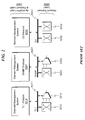
- Network elements (0115, 0116, 0125, 0126) as illustrated in FIG. 1 generally make use of many different communication protocols. This diversity in communications protocols increases the difficulty and time to customize a common network element manager system (EMS) (0113, 0114, 0123, 0124) for every network element using a different protocol in the system. For example, incorporating the individual protocols within the EMS generally increases the overall subsystem complexity, increases code size, probability of software error/failure, and compilation time. Thus, as illustrated in FIG. 2, the current state of the art is to incorporate each network element protocol (TL1, SNMP, Q3, etc.) within each EMS (0210, 0220, 0230). These protocols (0211, 0221, 0231) are then used to communicate with the various protocol-specific network elements (0212, 0213, 0222, 0223, 0232, 0233).
- T1, SNMP, Q3, etc. each network element protocol
- the code of the network manager system (0210, 0220, 0230) had to be revised and recompiled for each different protocol (0211, 0221, 0231) used by a network element (0212, 0213, 0222, 0223, 0232, 0233).
- Software developers maintaining EMS had to be very knowledgeable of the network element manager code and the structure of this system in order to make any necessary revisions to the software code.
- the level of software developer expertise in the prior art is significant and nontrivial, and the amount of time required to implement changes to the EMS is significant.
- a common software configuration implementing a network management function may include numerous Element Management System (EMS) components (0210, 0220, 0230) each of which implements a different protocol (TL1, SNMP, Q3, etc.) (0211, 0221, 0231). These protocols (0211, 0221, 0231) are integrated into each EMS component (0210, 0220, 0230) and constitute a combined Application Logic and Protocol Layer (0240).
- EMS Element Management System
- EMS embodiments (0210, 0220, 0230)
- the protocols they implement (TL1, SNMP, Q3, etc.) (0211, 0221, 0231) are necessary to support a variety of network switching and multiplexing equipment (0212, 0213, 0222, 0223, 0232, 0233) that by necessity or implementation requires a specific communication protocol.
- This Network Element (NE) layer (0250) may incur significant changes as new equipment is added and/or removed and new protocols or protocol extensions are incorporated in the various network elements (0212, 0213, 0222, 0223, 0232, 0233).
- the objects of the present invention are (among others) to circumvent the deficiencies in the prior art and affect the following objectives:
- the present invention can best be illustrated in terms of an exemplary network management application in which a wide variety of applications, such as Alarm Surveillance Manager (AS, a NML-layer application that allows one to monitor, acknowledge, and resynchronize alarms sent by a collection of NEs) (0301), Physical Network Managers (PNM, a NML-layer application that allows a network administrator to add/delete and supervise/unsupervised NEs) (0302), and the like along with their possible interface adapters (0313).
- AS Alarm Surveillance Manager
- PPM Physical Network Managers
- GEM Generic Element Manager Systems
- GEM/EMS Generic Element Manager Systems
- the GEM Application Server (0321) then communicates over an internal API (0330).
- This API is then interfaced to one or more generic protocol proxies (0331, 0332) that then communicate with the network elements (0351, 0352) via a network element protocol specific interface (0341, 0342).
- the architecture of the system illustrated in FIG. 3 differs significantly as compared to the prior art in that the GEM/EMS Application Server (0321) along with the associated internal API interface (0330) and generic proxies (0331, 0332) represent a new paradigm in the implement of network element management to control, supervise, and monitor the various network elements (0351, 0352) via a wide variety of network element specific protocols (0341, 0342).
- the invention is a system permitting a network Element Management System (EMS) to be maintained and modified without the huge software overhead of supporting a plethora of network protocols that are targeted towards a variety of network elements (NE).
- EMS network Element Management System
- NE network elements
- the present invention solves the problem present in the prior art by using a common gateway architecture (CGA) (0401) driven by an EMS (0400) designed to be generic across different types of network elements and different network element protocols.
- the architecture is best described as client/server based with a gateway/proxy (GP) layer (0450) that contains the protocol specific generic gateways.
- the GP layer (0450) is not required to have any specific network element knowledge but instead just needs to know the protocol used to communicate with the network elements (0412, 0413, 0422, 0423, 0432, 0433).
- the GP layer (0450) formats requests from the server layer (0440) into protocol specific requests and translates the protocol-specific responses into server objects/attributes.
- the GP layer (0450) is the only component directly interfacing with the network elements (0412, 0413, 0422, 0423, 0432, 0433) to setup or close connections, send commands and receive responses and monitor for events/alarms.
- the present invention may be aptly described in terms of exemplary system block diagrams and procedural flowcharts. While these items are sufficient to instruct one of ordinary skill in the art the teachings of the present invention, they should not be strictly construed as limiting the scope of the present invention.
- system block diagrams may be combined and rearranged with no loss of generality, and procedural steps may be added or subtracted, and rearranged in order to achieve the same effect with no loss of teaching generality.
- the present invention as depicted in the attached exemplary system block diagrams and procedural flowcharts is for teaching purposes only and may be reworked by one skilled in the art depending on the intended target application.
- PC personal computer
- the term 'personal computer' should be given a broad meaning in this regard, as in general any computing device may be utilized to implement the teachings of the present invention, and the scope of the invention is not limited just to personal computer applications.
- Intranet will be used generally to denote any network communication system or environment.
- Intranet will denote communications that are local to a given system or user, and Internet will describe communications in a more distant local.
- Internet will describe communications in a more distant local.
- the present invention specifically anticipates that in some implementations the GUI development framework (and/or its runtime component) will communicate with the data used to drive the GUI over the Internet.
- the application driving the user interface may reside on one computer system and the data used for presentation and control may be contained somewhere else on another computer system and be accessed via any number of networking protocols.
- API Application Programming Interface
- APIs Application Programming Interfaces
- SDKs Software Development Kits
- the present invention may be embodied in a variety of data structures in some preferred embodiments.
- the form of such data structures as described herein is only exemplary.
- One skilled in the art would quickly realize that a wide variety of other data structures could be used equivalently in this application. Therefore, no data structure contained herein should be interpreted as limiting the scope of the present invention.
- the present invention utilizes a Generic Element Management System (GEM/EMS) (0400) that interfaces with a Common Gateway Architecture (CGA) (0401) that communicates with a variety of generic proxies (0410, 0420, 0430, etc.). These proxies (0410, 0420, 0430) then communicate in a protocol-specific manner (0411, 0421, 0431) with a variety of network elements (0412, 0413, 0422, 0423, 0432, 0433) that may be from a variety of equipment vendors.
- the strength of this architecture lies in the ability to communicate with equipment of a variety of vendors without having to specifically code (and maintain) this support in the EMS (0400).
- the Common Gateway Architecture (0401) is a client/server architecture in which the Element Management System (EMS) (0400) takes the role of "client” and the protocol gateways/proxies (0410, 0420, 0430) take the role of "server”.
- EMS Element Management System
- the EMS (0400) defines all protocol-independent application logic while the gateways/proxies (0410, 0420, 0430) deal exclusively with protocol-specific knowledge.
- the present invention uses one protocol gateway/proxy per Network Element protocol (0411, 0421, 0431).
- the CGA (0401) defines a generic protocol-independent interface between client (EMS) (0400) and server (gateway/proxy) (0410, 0420, 0430), the CGA Interface (0401).
- EMS client
- gateway/proxy gateway/proxy
- each protocol gateway/proxy (0410, 0420, 0430) needs to implement this generic interface.
- the present invention can be thought of as incorporating an Application Layer (0440), a Gateway/Proxy Layer (0450), and a Network Element Layer (0460). Since the Application Layer (0440) in the present invention is represented as a Server, with corresponding Client functionality being incorporated in the Gateway/Proxy Layer (0450), the following discussion will detail these elements and how they interact.
- FIG. 5 illustrates an exemplary embodiment of the EMS Application Server Architecture (0500).
- the architecture (0500) can be split up into three logical parts: the Server Plug-in Framework (0510), the Domain Servers (0520) and a collection of Standard Generic Services (0530) available to all domain servers.
- the Server Plug-in Framework (0510) allows for subcomponents (i.e. functional domain managers) to be plugged into the system.
- Supported Domains configuration file (SupportedDomains.properties) (0511).
- Supported Domains configuration file is indexed by NE type and release and is consulted each time a new NE instance is added to the system.
- Domain Managers (0520) provide specific NM functionality for their domain. Each domain manager has its own name space and possibly shares (or provides access to) parts of his name space with other domain managers. Domain managers are also referred to as domain servers or domain servants.
- FIG. 5 Illustrated in FIG. 5 are exemplary domain servers (0520) including Equipment (0521), Facility (0522), Cross-Connection (0523), Test Access (0524), PM (0525), System Maintenance (0526), Alarm (0527), and NE Directory (0528) Managers.
- Equipment 0521
- Facility 0522
- Cross-Connection 0523
- Test Access 0524
- PM 0525
- System Maintenance 0526
- Alarm 0527
- NE Directory NE Directory Manager
- Standard Generic Services (0530) generally includes a collection of services available to all domain managers.
- the Persistency Service (0531) provides a repository for persistent data, like the list of NEs to be managed by the server with all the necessary address information to contact each NE.
- the Event Handler (0533) listens for autonomous messages coming from the different NEs, and dispatches those messages internally towards the relevant domain manager (alarm manager, database change handler.
- the Command Dispatcher (0534) interacts with the protocol specific gateway/proxy for sending commands to and receiving responses from the target Network Element.
- the Session Manager (0535) maintains information (operator profile) about each client connected to the server. It builds Session CORBA objects for each client. Clients then use their dedicated Session object to obtain a reference to their dedicated domain managers.
- the Security Manager limits the actions available to a particular client on an individual object or group of objects.
- the security manager interfaces with the security database (0537).
- This database contains Object Access Domains (OAD) and Functional Access Domains (FAD) associated with operator profiles.
- OAD Object Access Domains
- FAD Functional Access Domains
- the Management Information Base (0538) is a collection of objects used in the request routing process, i.e. the process of forwarding incoming requests to the right domain manager for domain specific processing.
- the MIB acts as a cache for subsequent requests to those domain managers that keep (parts of) their name space in memory (e.g., the equipment domain manager).
- the MIB provides convenient object retrieval/storage functionality.
- the gateway/proxy layer (0450) consists of proxies (0610) that format requests (0620) from the EMS (0400) application logic layer (0440) into protocol-specific requests (0640) and translates the protocol-specific responses (0630) into application logic layer (0440) objects/attributes for use by the EMS.
- the gateway/proxy layer (0450) is the only component directly interacting with the network elements (at the network element layer (0460)) to setup or close connections, to send commands and receive responses and to monitor for autonomous messages (alarms and events).
- the architecture depicted in FIGs. 3, 4, and 6 contrasts with the PRIOR ART architecture illustrated in FIG. 2 in that in the PRIOR ART architecture the application logic is network element protocol dependent. This means that all application logic needs to be revised (or event completely rewritten) when a new protocol is added to the network.
- CGA Common Gateway Architecture
- MIB Management Information Base
- FIG. 6 illustrates an exemplary high-level architecture (0700) common to all protocol gateways/proxies (0610) and illustrates an exemplary set of components comprising same.
- Each gateway/proxy (0610) is protocol specific, but network element implementation independent.
- the gateway/proxy requirements are:
- the protocol parser/translator (0612) merely defines the syntax of the commands, the responses and the autonomous messages. Each network element however defines the semantics of the commands, their input arguments and their result (output). These differences between network elements are handled in NE type and release dependent configuration files, stored in the protocol dictionary (0617).
- the protocol dictionary (0617) stores all command templates and the rules to parse individual object attributes out of command responses and autonomous messages.
- Command templates are the actual commands in the right syntax with placeholders for the command-input arguments.
- the rules to parse individual object attributes out of command responses and autonomous messages are regular expressions in case of the TL1 protocol.
- the dictionary implements the Q3 GDMO model and the attributes are immediately available as attributes on the managed objects defined in the GDMO model, with ASN.1 syntax.
- EMS and protocol gateways/proxies can be defined in the programming language of choice, or even in IDL, depending on the overall system requirements.
- An exemplary embodiment of this interface may be defined in Java as illustrated in FIGs. 8-9.
- a NameAndStringValue structure is the representation of a name-value pair in which both the name and the value are of type String.
- An AttributeValue structure is the representation of a name-value pair in which the name is of type String and the value is of type org.omg.CORBA.Any.
- An object of type org.omg.CORBA.Any can represent any type defined in IDL. The reason for using CORBA structures at this level is to avoid structure translation from EMS MIB to clients.
- the Response object is the protocol independent object used for passing information from gateway/proxy to the EMS.
- An example Response data structure could be as simple as the exemplary listing illustrated in FIG. 10.
- the above data structure resembles the definition of an SQL database table.
- the fields are Any structures and can therefore contain any pre-defined IDL data structure.
- the unique identification of each object in the response is included as one of the columns in this table. In case of the TL1 protocol, this unique identifier will be an AID; in case of the Q3 protocol, the unique identifier is an FDN.
- the EMS MIB has a mapping function to translate these unique identifiers into internal unique object identifiers. Typically, this mapping function is NE dependent.
- the commandId argument in the sendCommand() function is the unique identification for the action to be executed in the network element.
- the protocol gateway/proxy searches for this commandId in the protocol dictionary for the given network element type and release and finds the command template associated with this identifier.
- command identifiers are logical identifiers corresponding to high-level actions available in all network elements, no matter what their protocol is. Examples of such logical identifiers are: get, set, delete, create, login and logout. However, in order to provide 100% manageability, most of the command identifiers will be network element specific.
- the entityId argument in the sendCommand() function is the unique identification of the target object in the network element for the action.
- the entityId takes the form of a Fully Distinguished Name (FDN) structure.
- FDN is a sequence of Relative Distinguished Names (RDNs).
- RDN is a name-value pair in which the name is commonly referred to as the Distinguishing Name (DN).
- DN Distinguishing Name
- the inArgs argument in the sendCommand() function corresponds to the list of arguments of the command.
- the protocol gateway/proxy replaces each placeholder in the command template, with the value of the corresponding argument in the argument list.
- the outArgs argument in the sendCommand() function corresponds to the list of attributes to be returned by the command. Only the given attributes will appear in the Response structure.
- the Element Management System's internal object model needs to be protocol independent. More specifically, this requirement means the model needs to be able to store any number of attributes of any possible type.
- One way this can be achieved is by storing attribute-value pair lists, in which the value is of type org.omg.CORBA.Any, in a generic object class from which all other MIB object classes inherit. Specialization can be applied to better organize object functionality, hence facilitating the implementation of the application logic.
- FIG. 11 An example base object class definition is illustrated in FIG. 11. All member functions have intentionally been left out.
- This section describes a design pattern (as illustrated in FIG. 12) that may be used to broadly exemplify embodiments of the present invention (as opposed to providing an exemplary actual implementation).
- Each domain server uses this design pattern (1200) as a guideline for implementation, the details of which are described separately in this document.
- FIG. 12 illustrates a typical domain server. Each domain server supports the Plug-In interface. This interface includes functions to:
- each domain server publishes the following open CORBA interfaces:
- clients are lightweight: they handle nothing but presentation data and should therefore per definition be NE / protocol independent. They are of course function dependent, which could in fact be seen as NE dependence if a particular function is only available in one particular NE. This is however not part of the definition of NE independence as used throughout this document. Only handling presentation data means that no interpretation may be done of any attribute values returned by the server other than translate those values into user friendly, language dependent strings.
- a strongly typed interface is an interface where all functionality is available as specific functions with a specific set of typed arguments (hard-coded function signature).
- a weakly typed IDL interface provides a generic execute() function that takes an action ID and a namevalue-pair sequence as arguments. In case of a weakly typed interface, 100% manageability can still be achieved without becoming NE dependent in two ways:
- GEM uses both types of interfaces: each domain server (optionally) publishes its own strongly typed interface and all domain servers share the navigation interface which is weakly typed.
- the Client Architecture (1300) as illustrated in FIG. 13 looks very similar to the EMS Application Server Architecture (0500) illustrated in FIG. 5.
- the plug-in concept is also applied but here the plug-in components are commonly referred to as "snap-in" components.
- the Client Snap-In Framework allows for subcomponents (views) (1320) to be plugged into the system. This component takes care of initializing the browser (Navigation Tree View) through the dynamic loading of the snap-ins listed in a configuration file (1311). Each snap-in initializes its root node, which corresponds to the root node of the corresponding server-side plug-in. This is sufficient for the framework to be able to discover the rest of the name space including the functionality supported by each entity in the name space.
- Each Domain View (1321, 1322, 1323, 1324, 1325, 1326, 1327, 1329) has its own name space that is nothing more than a restricted view on the overall Object Model. Multiple different views can share objects.
- Each Domain View has a corresponding server-side Domain Manager (0520).
- Standard Generic Services (1330) are a collection of services available to all domain views (1320).
- the Persistency Service (1331) provides a repository for persistent data like common configuration files and storage of user preferences (1332).
- the Event Manager (1333) listens for autonomous messages coming from the event service and updates the model accordingly.
- the Model uses the event manager's services to register for object creation, object deletion and attribute value change notifications.
- the Controller makes sure all views on the model are kept up to date by applying the model-viewcontroller design pattern. It supports multiple views on the same data. Each modeled object maintains a reference count so that information can be garbage collected in the model as soon as nobody is still visualizing that data.
- the Commander (1335) provides the views with the interface towards the server. It makes the IDL layer invisible to view implementers.
- This object provides an API which is basically a 1-to-1 mapping from the functionality defined on the IDL interface with the difference that for each available function a synchronous and an asynchronous version is available.
- the Commander object intercepts the responses to each request in order to keep the MIB up-to-date without client-side development effort and to act as a cache for subsequent requests.
- the Commander object only needs to be extended for the optional specific interface supported by some domain servant.
- the Garbage Collector (1336) is a configurable component that removes objects from the MIB, based on their reference count.
- the garbage collector can be configured to run automatically at certain intervals, manually or when the number of garbage collectable objects reaches some predefined (configurable) value.
- the Caching Service (1337) is a configurable component that artificially keeps the reference count above 0 for objects that are not currently being displayed, but are good candidates for becoming visible again in the near future.
- the caching service has a configurable View stack size. Whenever a view becomes invisible (replaced by some other view), it is pushed onto the View stack. When a view drops off the stack, all of its objects are being invalidated (reference count set to 0) so that they become food for the garbage collector.
- the Common Object Model (1338) is a transient collection of objects organized in a tree structure. The collection of all objects in this Model is the overall name space.
- the model is built up without any programming effort required from the view implementers.
- the model acts as a cache for subsequent requests for the same information.
- a view implementer doesn't know when a request for information was satisfied locally or remotely.
- the model also doesn't require any user intervention for keeping its information up-to-date.
- Event registration is done dynamically based on what is currently being stored in the model and therefore what is currently being displayed somewhere.
- the actual objects stored in the model are fully customizable through user-supplied object factories.
- FIG. 14 An exemplary embodiment of one such deployment (1400) is illustrated in FIG. 14. This example may in many circumstances represent the "normal" deployment situation. This means that the setups described here are not the only “working” ones, but that they are the “desired” ones in terms of expected performance and added value in many practical systems implementing the present invention.
- the optimal implementation of the present invention permits one GEM server per host to have an unlimited number of clients. These clients are either GEM GUI instances, protocol adapters towards external applications or higher level NML applications. Each client typically talks to just one server.
- the interface between client and server is CORBA based and a client knows how to contact the server by means of the Naming Service.
- the IOR of the Naming Service is set in a client-side (and server-side) configuration file (ORB.properties).
- the Naming Service can be running on the same machine or on a remote machine in the same network.
- GEM servers can co-exist on the same machine (1410, 1430) and each server typically manages multiple NEs (1411). Each NE should however be managed by at most one GEM server (1412), while at the same time, another type of manager is allowed to operate on the same NE (e.g., TL1 terminal) (1421).
- GEM server consists of multiple domain servers (plug-in components) which are all registered with the Naming Service and therefore can be distributed across multiple machines (1431) in the same network.
- Naming Service A detailed technical description of the Naming Service can be obtained by referring to the CORBA Standard Services documentation ("The Common Object Request Broker: Architecture and Specification" at ftp://ftp.omg.org/pub/docs/formal/98-12-01.pdf). This section only explains how the Naming Service is being used in the context of the present invention.
- FIG. 15 illustrates an exemplary embodiment of the Naming Policy (1500).
- the figure shows an example in which two (2) GEM Application Servers (EMLs) exist.
- EMLs GEM Application Servers
- Their names (“GEM_1” and "GEM_2”) correspond to the NeGroupId as used by PNM (0302) that uniquely identifies a group of NEs with a certain EMS.
- the "SessionManager” object reference is the entry point for obtaining references (IORs) to domain managers.
- AS also requires the name of the channel on which alarms are being sent, to be "X733EventChannel”.
- PNM requires the name of the channel on which state changes are being sent, to be "X721EventChannel”.
- these two identifiers are typically defined in an IDL definition file.
- NE Management is the process of adding NEs to the network, removing NEs from the network and making the NEs available or unavailable for management operations. All of these operations are initiated from the Physical Network Management (PNM) (0302) application user interface.
- PPM Physical Network Management
- an NE can be in:
- NEs can be added via the PNM user interface.
- the information entered is:
- PNM generates an internal identification for the NE. This identification cannot be modified, as opposed to the logical NE name. Clients work with the logical NE name, while the server works with the internal identification.
- NEs are removed from the system via the PNM-USM interface. The following steps are performed:
- NE Connection Management includes the process of establishing connections with the NE and tearing down those connections. It also includes the detection of broken connections and automatically reconnecting. Login and logout are also categorized under this header.
- connection to an NE is a TCP/IP connection (socket).
- the actual connection protocol used by the NE itself can be different, e.g. X.25, ACSE, RS232), the complexities of which are hidden by the communications server. The following steps are performed during the connection process:
- the re-alignment thread starts the re-connect process when the communications state is not ENABLED and starts the alignment process when the MIB alignment state is MISALIGNED.
- the general procedure for this re-connection is as follows:
- FIG. 17 illustrates an exemplary complement of CGA interface modules (1700) that are described in detail in the following sections
- FIG. 18 A generalized flowchart for adding a network element to the element management system is illustrated in FIG. 18 (1800). The method generally follows the following steps as detailed in FIG. 18:
- FIG. 19 A generalized flowchart for removing a network element from the element management system is illustrated in FIG. 19 (1900). The method generally follows the following steps as detailed in FIG. 19:
- the protocol gateway doesn't have any NE specific knowledge built in.
- the gateway however needs to be configured for each network element type. This method instructs the gateway to process the protocol dictionary for the given network element type and release. Internally, the gateway will build up a map of command identifier to protocol template strings and a map of command identifier to rules to parse attribute values out of the command response.
- FIG. 20 A generalized flowchart for configuring a gateway is illustrated in FIG. 20 (2000). The method generally follows the following steps as detailed in FIG. 20: 1.
- the NE address is set by this function.
- FIG. 21 A generalized flowchart for setting the network element address is illustrated in FIG. 21 (2100). The method generally follows the following steps as detailed in FIG. 21:
- This method establishes a socket connection with the network element on the address set by the previous function.
- the function starts by setting the network element's communications state to "connecting”. Then, the function tries to open a socket connection with the NE. If this fails, the communications state is set to "disconnected” and an exception is thrown. If the socket connection was successfully established, the communications state is set to "connected”.
- FIG. 22 A generalized flowchart for connection to a network element is illustrated in FIG. 22 (2200). The method generally follows the following steps as detailed in FIG. 22:
- This method closes the socket connection with the network element associated with this gateway.
- the function start by setting the network element's communications state to "disconnecting”. Then, the function closes the socket connection and sets the communications state to "disconnected”.
- FIG. 23 A generalized flowchart for disconnecting from a network element is illustrated in FIG. 23 (2300). The method generally follows the following steps as detailed in FIG. 23:
- a polling cycle continuously monitoring the responsiveness of the network element is started.
- the server logs in to the network element by sending the LOGIN command using the "send command to NE" function).
- This function uses a timer to periodically send a command with limited overhead (e.g. RTRV-HDR in case of TL1 NEs) to the network element.
- RTRV-HDR limited overhead
- FIG. 24 A generalized flowchart for performing this connectivity check / ping cycle is illustrated in FIG. 24 (2400). The method generally follows the following steps as detailed in FIG. 24:
- Alarms, database change messages, threshold crossing alerts, etc. are all examples of autonomous messages. These messages are spontaneously sent by the NE to the server. As this happens asynchronously, the server needs to register a callback with the gateway. Each time an autonomous message is received by the proxy, the proxy calls the handleMessage() method defined in callback object for all registered callbacks.
- FIG. 25 A generalized flowchart for registering autonomous message callbacks is illustrated in FIG. 25 (2500). The method generally follows the following steps as detailed in FIG. 25:
- This function sends the command associated with the given command identifier and the given command-input arguments to the object identified by the given FDN.
- the command also takes the list of expected output arguments as input.
- the function first checks if the communications state is currently "connected”. If not, an exception is thrown. The function searches for the given command identifier in the protocol dictionary. If the command identifier was not found, the CommandNotFound exception is thrown. Else, the command template associated with the command identifier is retrieved from the protocol dictionary. The function then replaces the placeholders in the command template with the given values for the corresponding attributes. The function then generates a unique (sequential) number that will act as the unique identification for the command execution. The placeholder for the CTAG attribute is replaced by this unique number.
- the command response sends this unique number back, so that the system can correlate the response with a command in a multi-threaded environment with asynchronous command executions.
- the function sends the command over the socket connection and stores the command in a correlation map.
- the current thread is put to sleep.
- a sequence of characters is read from the socket until a predefined termination character is read (';' in case of TL1).
- the termination character defines the end of a message.
- the message type is extracted. This type identifies the message as an autonomous message or as a command response. If the message is an autonomous message, the registered callback's handleMessage() method is called (see registerCallback() function) for processing. If the message corresponds to a command response, the correlation tag is extracted from it and the correlation map is searched for the presence of this tag. If the tag is not present, this message is discarded. If the tag was found, the corresponding command object is retrieved from the map.
- the command's response is added to the command object and all sleeping threads are notified. This wakes up a randomly selected send-thread. The awoken thread checks whether his command object now has the response set. If so, the function returns the response. Otherwise, the thread is put back to sleep and the next randomly selected send-thread is awoken until no more sendthreads are available.
- FIGs. 26-30 A generalized flowchart for sending commands to a network element is illustrated in FIGs. 26-30 (2600). The method generally follows the following steps as detailed in FIGs. 26-30:
- FIGs. 28-30 A generalized flowchart for retrieving command responses from a network element is illustrated in FIGs. 28-30 (2600). The method generally follows the following steps as detailed in FIGs. 28-30:
- Processing of sleep request threads associated with sending and retrieving network element commands is illustrated in FIG. 30 (3000).
- GUI graphical user interface
- the functional elements of the present invention are widely applicable to situations involving multiple types of remote equipment sourced from a variety of hardware and software manufacturers. Since the present invention breaks the compile-time link between network element management and the tool used to perform the management function, this permits a wide variety of applications in situations where networks must be grown dynamically by adding hardware and software, but which must remain up and functional during this upgrade process.
- CGA Element Manager Common Gateway Architecture
- EMS network Element Management System
- protocol gateways/proxies take the role of “server”
- the EMS defines all protocol-independent application logic while the gateways/proxies deal exclusively with protocol-specific knowledge.
- CGA Common Gateway Architecture
- the Common Gateway Architecture (CGA) allows the application logic to be shared among protocols, using a protocol independent data model.
- a significant aspect of the software maintenance in EMS systems is that since network elements (NEs) use many different protocols, there exists a difficulty and time lag associated with customizing a common network element manager for every network element using a different protocol in a given system.
- Modifications to the system typically require incorporation of new code into the network element manager with associated recompilation of the entire network element manager subsystem.
- the present invention solves this problem by using a common gateway architecture designed to be generic across different types of NEs and different network protocols. This permits NEs to be added incrementally without recompilation of the entire network element manager, thus reducing overall software maintenance overhead.
Landscapes
- Engineering & Computer Science (AREA)
- Computer Networks & Wireless Communication (AREA)
- Signal Processing (AREA)
- Computer Security & Cryptography (AREA)
- Human Computer Interaction (AREA)
- Computer And Data Communications (AREA)
- Data Exchanges In Wide-Area Networks (AREA)
Abstract
An Element Manager Common Gateway Architecture (CGA) system and method incorporating a client/server architecture in which a network Element Management System (EMS) takes the role of "client" and the protocol gateways/proxies take the role of "server" is disclosed. The EMS defines all protocol-independent application logic while the gateways/proxies deal exclusively with protocol-specific knowledge. The Common Gateway Architecture (CGA) allows the application logic to be shared among protocols, using a protocol independent data model. A significant aspect of the software maintenance in EMS systems is that since network elements (NEs) use many different protocols, there exists a difficulty and time lag associated with customizing a common network element manager for every network element using a different protocol in a given system. Modifications to the system typically require incorporation of new code into the network element manager with associated recompilation of the entire network element manager subsystem. The present invention solves this problem by using a common gateway architecture designed to be generic across different types of network elements and different network protocols. This permits network elements to be added incrementally without recompilation of the entire network element manager, thus reducing overall software maintenance overhead. <IMAGE>
Description
The present invention is related in the general area
of network Element Management Systems (EMS) and software
techniques which may be used to minimize the maintenance
overhead of EMS when responding to changes in network
protocols and/or incorporation of new/modified network
elements (NE).
As illustrated in FIG. 1, the present invention may
have application in situations where there are one or more
telecommunications networks (0110, 0120) that may or may
not contain equipment from different vendors. The network
equipment elements (NE) used within these networks (0115,
0116, 0125, 0126) may take many forms, including but not
limited to switch gear, multiplexers, and the like. These
network elements (0115, 0116, 0125, 0126) are generally
under control of one or more computer systems (0111, 0121)
that are controlled by computer software (0112, 0122) that
may be stored on a variety of storage media. This computer
software generally takes the form of one or more network
element managers (0113, 0114, 0123, 0124) that control and
monitor the network elements (0115, 0116, 0125, 0126) that
comprise constituent components of the telecommunication
networks (0110, 0120).
The present invention deals specifically with
implementations of the network element manager (0113, 0114,
0123, 0124) as they relate to the overall control and
monitoring of the various network elements (0115, 0116,
0125, 0126) within the context of one or more
telecommunications networks (0110, 0120).
To minimize the verbosity of this document, a variety
of abbreviations and definitions will be provided to aid
the reader. This information may be applicable to the prior
art, the present invention, or some combination of the two.
No assumption should be made regarding the applicability of
this information except as referenced within the applicable
preferred embodiment description of the present invention
as given later in this document.
The following acronyms will be used throughout this
document:
- AID
- Native Identifier for TL1 objects
- AMC
- Alcatel Management Console
- AMV
- ALMAP View (GUI Framework)
- API
- Application Programming Interface
- AS/ASM
- Alarm Surveillance Manager
- ANS
- Alcatel Network Systems
- ASN.1
-
Abstract Syntax Notation 1 - CGA
- Common Gateway Architecture
- CORBA
- Common Object Request Broker Architecture (See Understanding CORBA by Randy Otte, Paul Patrick, and Mark Roy, (ISBN 0-13-459884-9, 1996); Object-Oriented Frameworks Using C++ and CORBA by Vishwajit Aklecha (ISBN 1-57610-403-6, 1999); Advanced CORBA Programming with C++ by Michi Henning and Steve Vinoski (ISBN 0-201-37927-9, 1999); 1998 OMG PDF document "The Common Object Request Broker: Architecture and Specification" at ftp://ftp.omg.org/pub/docs/formal/98-12-01.pdf for a complete specification of the CORBA system).
- CMIP
- Common Management Information Protocol
- CMISE
- Common Management Information Service Element
- CRB
- Change Review Board
- DDTS
- Fault Report System
- DII
- Dynamic Invocation Interface
- DME
- Distributed Management Environment
- DN
- Distinguished Name (name in a NVP)
- EML
- Element Management Layer
- EMS
- Element Management System
- FAD
- Functional Access Domain
- FDN
- Fully Distinguished Name
- GDMO
- Guidelines for the Definition of Managed Objects
- GEM
- Generic Element Manager
- GP
- Gateway/Proxy
- GUI
- Graphical User Interface
- GW
- Gateway
- HPOV
- HP Open View
- IDL
- Interface Description Language
- IDL
- Interface Description Language
- IM
- Information Model
- IOR
- Interoperable Object Reference
- IP
- Internet Protocol
- LIT
- Local Integration Test
- LOC
- Lines of Code
- LTN
- Local Transport Networks
- MIB
- Management Information Base
- MSAN
- Multi Service Access Node
- NE
- Network Element
- NML
- Network Management Layer
- NMS
- Network Management System
- NVP
- Name-Value Pair
- OAD
- Object Access Domain
- OMG
- Object Management Group
- OS
- Operations System (e.g. Network Management Application)
- OVE
- Approved instructions for engineering activities
- PNM
- Physical Network Manager
- PY
- Person Years
- Q3
- An object-oriented network management protocol
- RDN
- Relative Distinguished Name
- RTC
- Real Time Clock
- SDH
- Synchronous Digital Hierarchy
- SIT
- System Integration Test
- SITC
- SIT completed
- SMF
- System Management Framework
- SNMP
- Simple Network Management Protocol
- SONET
- Synchronous Optical Network
- SQL
- Structured Query Language
- SVT
- System Validation Test
- SW
- Software
- TLD
- Top Level Design
- TL1
-
Transaction Language 1 - UML
- Unified Modeling Language
- X.25
- A communications protocol
These acronyms must be interpreted within their
context as describing either the prior art (in some
contexts) or the present invention and its embodiments.
Some terms will apply to both the prior art and the present
invention while others may apply to one or neither of
these.
The following definitions will be used throughout this
document in describing the prior art as well as the present
invention and its embodiments:
- Fine-grained model - an object-oriented model in which there is an object instance for each entity in the problem domain. A fine-grained model typically defines an object class for each entity type in the problem domain and deals with lots of object instances (thousands to millions of objects). Reference FIG. 16 (1603) for a typical example of this model.
- Coarse-grained model - a semi-object-oriented model in which there is only a very limited amount of object instances. A coarse-grained model typically only defines a limited number of object classes and deals with a very limited number of object instances (tens of objects). Reference FIG. 16 (1602) for a typical example of this model.
- Facade object - an object that acts as a front (or shell) for dispatching requests to an actual modeled object. A façade object is the key towards the definition of coarse-grained modules.
- Hierarchical model - an object oriented model in which parent-child relationships are defined. Reference FIG. 16 (1601) for a typical example of this model.
- Fully Distinguished Name - a unique identifier for objects in hierarchical object modules. A FDN is a sequence of Relative Distinguished Names (RDNs). An RDN is a name-value pair (NVP) in which the name is commonly referred to as the Distinguished Name (DN). Each child of the same parent has a unique RDN. In other words, each RDN is unique within its parent's context.
- Object View - the definition of the (sub)set of attributes and the (sub)set of operations visible on the object. Different views on the same object have a different set of attributes and/or a different set of operations available on the object.
Network elements (NE) (0115, 0116, 0125, 0126) as
illustrated in FIG. 1 generally make use of many different
communication protocols. This diversity in communications
protocols increases the difficulty and time to customize a
common network element manager system (EMS) (0113, 0114,
0123, 0124) for every network element using a different
protocol in the system. For example, incorporating the
individual protocols within the EMS generally increases the
overall subsystem complexity, increases code size,
probability of software error/failure, and compilation
time. Thus, as illustrated in FIG. 2, the current state of
the art is to incorporate each network element protocol
(TL1, SNMP, Q3, etc.) within each EMS (0210, 0220, 0230).
These protocols (0211, 0221, 0231) are then used to
communicate with the various protocol-specific network
elements (0212, 0213, 0222, 0223, 0232, 0233).
Prior to the present invention, as illustrated in FIG.
2 the code of the network manager system (EMS) (0210, 0220,
0230) had to be revised and recompiled for each different
protocol (0211, 0221, 0231) used by a network element
(0212, 0213, 0222, 0223, 0232, 0233). Software developers
maintaining EMS had to be very knowledgeable of the network
element manager code and the structure of this system in
order to make any necessary revisions to the software code.
Thus, the level of software developer expertise in the
prior art is significant and nontrivial, and the amount of
time required to implement changes to the EMS is
significant.
As illustrated in FIG. 2, a common software
configuration implementing a network management function
may include numerous Element Management System (EMS)
components (0210, 0220, 0230) each of which implements a
different protocol (TL1, SNMP, Q3, etc.) (0211, 0221,
0231). These protocols (0211, 0221, 0231) are integrated
into each EMS component (0210, 0220, 0230) and constitute a
combined Application Logic and Protocol Layer (0240).
The rationale for various EMS embodiments (0210, 0220,
0230) is that the protocols they implement (TL1, SNMP, Q3,
etc.) (0211, 0221, 0231) are necessary to support a variety
of network switching and multiplexing equipment (0212,
0213, 0222, 0223, 0232, 0233) that by necessity or
implementation requires a specific communication protocol.
This Network Element (NE) layer (0250) may incur
significant changes as new equipment is added and/or
removed and new protocols or protocol extensions are
incorporated in the various network elements (0212, 0213,
0222, 0223, 0232, 0233).
As each of these network changes is incurred, the EMS
software must be recompiled with each new protocol change
to incorporate this new network management functionality
into the overall system. This creates a significant burden
on software management personnel, as the tight integration
of the application logic and the network element protocol
layer within the EMS makes this system difficult to
maintain and prone to errors in software development and
maintenance.
Accordingly, the objects of the present invention are
(among others) to circumvent the deficiencies in the prior
art and affect the following objectives:
While these objectives should not be understood to
limit the teachings of the present invention, in general
these objectives are achieved in part or in whole by the
disclosed invention that is discussed in the following
sections. One skilled in the art will no doubt be able to
select aspects of the present invention as disclosed to
affect any combination of the objectives described above.
Referencing FIG. 3, the present invention can best be
illustrated in terms of an exemplary network management
application in which a wide variety of applications, such
as Alarm Surveillance Manager (AS, a NML-layer application
that allows one to monitor, acknowledge, and resynchronize
alarms sent by a collection of NEs) (0301), Physical
Network Managers (PNM, a NML-layer application that allows
a network administrator to add/delete and
supervise/unsupervised NEs) (0302), and the like along with
their possible interface adapters (0313). In this scenario
one or more Generic Element Manager Systems (GEM/EMS)
(0311, 0312) communicates with a Generic Element Manager
Application Server subsystem (0321) via a standard software
interface such as CORBA (0320). The GEM Application Server
(0321) then communicates over an internal API (0330). This
API is then interfaced to one or more generic protocol
proxies (0331, 0332) that then communicate with the network
elements (0351, 0352) via a network element protocol
specific interface (0341, 0342).
The architecture of the system illustrated in FIG. 3
differs significantly as compared to the prior art in that
the GEM/EMS Application Server (0321) along with the
associated internal API interface (0330) and generic
proxies (0331, 0332) represent a new paradigm in the
implement of network element management to control,
supervise, and monitor the various network elements (0351,
0352) via a wide variety of network element specific
protocols (0341, 0342).
Briefly, the invention is a system permitting a
network Element Management System (EMS) to be maintained
and modified without the huge software overhead of
supporting a plethora of network protocols that are
targeted towards a variety of network elements (NE).
As illustrated in FIG. 4, the present invention solves
the problem present in the prior art by using a common
gateway architecture (CGA) (0401) driven by an EMS (0400)
designed to be generic across different types of network
elements and different network element protocols. The
architecture is best described as client/server based with
a gateway/proxy (GP) layer (0450) that contains the
protocol specific generic gateways. The GP layer (0450) is
not required to have any specific network element knowledge
but instead just needs to know the protocol used to
communicate with the network elements (0412, 0413, 0422,
0423, 0432, 0433). The GP layer (0450) formats requests
from the server layer (0440) into protocol specific
requests and translates the protocol-specific responses
into server objects/attributes. The GP layer (0450) is the
only component directly interfacing with the network
elements (0412, 0413, 0422, 0423, 0432, 0433) to setup or
close connections, send commands and receive responses and
monitor for events/alarms.
For a fuller understanding of the advantages provided
by the invention, reference should be made to the following
detailed description together with the accompanying
drawings wherein:
While this invention is susceptible of embodiment in
many different forms, there is shown in the drawings and
will herein be described in detailed preferred embodiment
of the invention with the understanding that the present
disclosure is to be considered as an exemplification of the
principles of the invention and is not intended to limit
the broad aspect of the invention to the embodiment
illustrated.
The numerous innovative teachings of the present
application will be described with particular reference to
the presently preferred embodiment, wherein these
innovative teachings are advantageously applied to the
particular problems of an ELEMENT MANAGER COMMON GATEWAY
ARCHITECTURE SYSTEM AND METHOD. However, it should be
understood that this embodiment is only one example of the
many advantageous uses of the innovative teachings herein.
In general, statements made in the specification of the
present application do not necessarily limit any of the
various claimed inventions. Moreover, some statements may
apply to some inventive features but not to others.
Throughout the discussion in this document the
following definitions will be utilized:
The present invention may be aptly described in terms
of exemplary system block diagrams and procedural
flowcharts. While these items are sufficient to instruct
one of ordinary skill in the art the teachings of the
present invention, they should not be strictly construed as
limiting the scope of the present invention. One skilled in
the art will be aware that system block diagrams may be
combined and rearranged with no loss of generality, and
procedural steps may be added or subtracted, and rearranged
in order to achieve the same effect with no loss of
teaching generality. Thus, it should be understood that the
present invention as depicted in the attached exemplary
system block diagrams and procedural flowcharts is for
teaching purposes only and may be reworked by one skilled
in the art depending on the intended target application.
Throughout the discussion herein there will be
examples provided that utilize personal computer (PC)
technologies to illustrate the teachings of the present
invention. The term 'personal computer' should be given a
broad meaning in this regard, as in general any computing
device may be utilized to implement the teachings of the
present invention, and the scope of the invention is not
limited just to personal computer applications.
Throughout the discussion herein the terms Internet
and Intranet will be used generally to denote any network
communication system or environment. Generally the term
Intranet will denote communications that are local to a
given system or user, and Internet will describe
communications in a more distant local. One skilled in the
art will recognize that these terms are arbitrary within
the contexts of modern communication networks and in no way
limitive of the scope of the present invention.
The present invention specifically anticipates that in
some implementations the GUI development framework (and/or
its runtime component) will communicate with the data used
to drive the GUI over the Internet. Thus, the application
driving the user interface may reside on one computer
system and the data used for presentation and control may
be contained somewhere else on another computer system and
be accessed via any number of networking protocols.
While the present invention may be in part implemented
using standard Application Programming Interfaces (APIs)
such as Software Development Kits (SDKs) and the like,
there is no requirement that the present invention be
implemented using these tools.
Additionally, while the present invention may be
implemented to advantage using a variety of Microsoft®
operating systems (including a variety of Windows™
variants), nothing should be construed to limit the scope
of the invention to these particular software components.
In particular, the system and method as taught herein may
be widely implemented in a variety of systems, some of
which may incorporate a graphical user interface. Some
examples of these include HP-UX™, LINUX™, SOLARIS, and
UNIX™ (and its variants), among others.
The present invention may be embodied in a variety of
data structures in some preferred embodiments. However, the
form of such data structures as described herein is only
exemplary. One skilled in the art would quickly realize
that a wide variety of other data structures could be used
equivalently in this application. Therefore, no data
structure contained herein should be interpreted as
limiting the scope of the present invention.
As illustrated in FIG. 4, the present invention
utilizes a Generic Element Management System (GEM/EMS)
(0400) that interfaces with a Common Gateway Architecture
(CGA) (0401) that communicates with a variety of generic
proxies (0410, 0420, 0430, etc.). These proxies (0410,
0420, 0430) then communicate in a protocol-specific manner
(0411, 0421, 0431) with a variety of network elements
(0412, 0413, 0422, 0423, 0432, 0433) that may be from a
variety of equipment vendors. The strength of this
architecture lies in the ability to communicate with
equipment of a variety of vendors without having to
specifically code (and maintain) this support in the EMS
(0400).
Referencing FIG. 4, the Common Gateway Architecture
(CGA) (0401) is a client/server architecture in which the
Element Management System (EMS) (0400) takes the role of
"client" and the protocol gateways/proxies (0410, 0420,
0430) take the role of "server". The EMS (0400) defines all
protocol-independent application logic while the
gateways/proxies (0410, 0420, 0430) deal exclusively with
protocol-specific knowledge.
Generally, the present invention uses one protocol
gateway/proxy per Network Element protocol (0411, 0421,
0431). The CGA (0401) defines a generic protocol-independent
interface between client (EMS) (0400) and
server (gateway/proxy) (0410, 0420, 0430), the CGA
Interface (0401). In other words, each protocol
gateway/proxy (0410, 0420, 0430) needs to implement this
generic interface.
From FIG. 4, it is clear that the present invention
can be thought of as incorporating an Application Layer
(0440), a Gateway/Proxy Layer (0450), and a Network Element
Layer (0460). Since the Application Layer (0440) in the
present invention is represented as a Server, with
corresponding Client functionality being incorporated in
the Gateway/Proxy Layer (0450), the following discussion
will detail these elements and how they interact.
FIG. 5 illustrates an exemplary embodiment of the EMS
Application Server Architecture (0500). The architecture
(0500) can be split up into three logical parts: the Server
Plug-in Framework (0510), the Domain Servers (0520) and a
collection of Standard Generic Services (0530) available to
all domain servers.
The Server Plug-in Framework (0510) allows for subcomponents
(i.e. functional domain managers) to be plugged
into the system.
The components that are available in the system are
read from a Supported Domains configuration file
(SupportedDomains.properties) (0511). As different types of
Network Elements possibly support different subsets of
Network Management functions, the Supported Domains
configuration file is indexed by NE type and release and is
consulted each time a new NE instance is added to the
system.
When a request to perform a certain NM function comes
in, the responsible domain server is looked up and when no
such server is available for the given NE instance, an
OperationNotSupported exception is thrown by the system.
Domain Managers (plug-ins) (0520) provide specific NM
functionality for their domain. Each domain manager has its
own name space and possibly shares (or provides access to)
parts of his name space with other domain managers. Domain
managers are also referred to as domain servers or domain
servants.
Illustrated in FIG. 5 are exemplary domain servers
(0520) including Equipment (0521), Facility (0522), Cross-Connection
(0523), Test Access (0524), PM (0525), System
Maintenance (0526), Alarm (0527), and NE Directory (0528)
Managers. One skilled in the art will recognize that a wide
variety of other plug-ins (0529) are also possible and
supported by this architecture.
Standard Generic Services (0530) generally includes a
collection of services available to all domain managers.
The Persistency Service (0531) provides a repository
for persistent data, like the list of NEs to be managed by
the server with all the necessary address information to
contact each NE.
The Event Handler (0533) listens for autonomous
messages coming from the different NEs, and dispatches
those messages internally towards the relevant domain
manager (alarm manager, database change handler.
The Command Dispatcher (0534) interacts with the
protocol specific gateway/proxy for sending commands to and
receiving responses from the target Network Element.
The Session Manager (0535) maintains information
(operator profile) about each client connected to the
server. It builds Session CORBA objects for each client.
Clients then use their dedicated Session object to obtain a
reference to their dedicated domain managers.
The Security Manager (0536) limits the actions
available to a particular client on an individual object or
group of objects. The security manager interfaces with the
security database (0537). This database contains Object
Access Domains (OAD) and Functional Access Domains (FAD)
associated with operator profiles.
The Management Information Base (MIB) (0538) is a
collection of objects used in the request routing process,
i.e. the process of forwarding incoming requests to the
right domain manager for domain specific processing. The
MIB acts as a cache for subsequent requests to those domain
managers that keep (parts of) their name space in memory
(e.g., the equipment domain manager). The MIB provides
convenient object retrieval/storage functionality.
Referencing the Gateway/Proxy Layer High Level
Overview in FIG. 6, the gateway/proxy layer (0450) consists
of proxies (0610) that format requests (0620) from the EMS
(0400) application logic layer (0440) into protocol-specific
requests (0640) and translates the protocol-specific
responses (0630) into application logic layer
(0440) objects/attributes for use by the EMS. The
gateway/proxy layer (0450) is the only component directly
interacting with the network elements (at the network
element layer (0460)) to setup or close connections, to
send commands and receive responses and to monitor for
autonomous messages (alarms and events).
The architecture depicted in FIGs. 3, 4, and 6
contrasts with the PRIOR ART architecture illustrated in
FIG. 2 in that in the PRIOR ART architecture the
application logic is network element protocol dependent.
This means that all application logic needs to be revised
(or event completely rewritten) when a new protocol is
added to the network.
The Common Gateway Architecture (CGA) illustrated in
FIG. 6 allows the application logic (0400, 0440) to be
shared among protocols, using a protocol independent data
model, also called a Management Information Base (MIB). It
is the responsibility of the protocol gateways/proxies
(0410, 0420, 0430, 0610) to translate the data structures
the MIB is built up with, into protocol-specific data
structures (0640) and vice versa.
FIG. 6 illustrates an exemplary high-level
architecture (0700) common to all protocol gateways/proxies
(0610) and illustrates an exemplary set of components
comprising same. Each gateway/proxy (0610) is protocol
specific, but network element implementation independent.
The gateway/proxy requirements are:
- Manage the connections to the network elements, including automatically re-establishing connections when they get lost (0616).
- Match network element responses with EMS requests, including correlation of linked replies (0614).
- Parse (0612) and report autonomous messages (0615).
- Be network element independent (0612).
- Support multiple network element connections at the same time (0616).
- Be multi-threaded to handle multiple commands at the same time.
- Implement the CGA interface (0611).
The protocol parser/translator (0612) merely defines
the syntax of the commands, the responses and the
autonomous messages. Each network element however defines
the semantics of the commands, their input arguments and
their result (output). These differences between network
elements are handled in NE type and release dependent
configuration files, stored in the protocol dictionary
(0617).
For each network element type/release, the protocol
dictionary (0617) stores all command templates and the
rules to parse individual object attributes out of command
responses and autonomous messages. Command templates are
the actual commands in the right syntax with placeholders
for the command-input arguments. The rules to parse
individual object attributes out of command responses and
autonomous messages are regular expressions in case of the
TL1 protocol. In case of the Q3 protocol, the dictionary
implements the Q3 GDMO model and the attributes are
immediately available as attributes on the managed objects
defined in the GDMO model, with ASN.1 syntax. One skilled
in the art will quickly realize that a wide variety of
protocols exist and that for each of these supported by the
CGA, there must exist corresponding translation tables
within the protocol dictionary (0617).
The generic interface between EMS and protocol
gateways/proxies can be defined in the programming language
of choice, or even in IDL, depending on the overall system
requirements. An exemplary embodiment of this interface may
be defined in Java as illustrated in FIGs. 8-9.
The definition of Address and all exceptions is left
unspecified. A NameAndStringValue structure is the
representation of a name-value pair in which both the name
and the value are of type String. An AttributeValue
structure is the representation of a name-value pair in
which the name is of type String and the value is of type
org.omg.CORBA.Any. An object of type org.omg.CORBA.Any can
represent any type defined in IDL. The reason for using
CORBA structures at this level is to avoid structure
translation from EMS MIB to clients.
The Response object is the protocol independent object
used for passing information from gateway/proxy to the EMS.
An example Response data structure could be as simple as
the exemplary listing illustrated in FIG. 10.
The above data structure resembles the definition of
an SQL database table. The fields are Any structures and
can therefore contain any pre-defined IDL data structure.
The unique identification of each object in the response is
included as one of the columns in this table. In case of
the TL1 protocol, this unique identifier will be an AID; in
case of the Q3 protocol, the unique identifier is an FDN.
The EMS MIB has a mapping function to translate these
unique identifiers into internal unique object identifiers.
Typically, this mapping function is NE dependent.
The commandId argument in the sendCommand() function
is the unique identification for the action to be executed
in the network element. The protocol gateway/proxy searches
for this commandId in the protocol dictionary for the given
network element type and release and finds the command
template associated with this identifier.
Ideally, command identifiers are logical identifiers
corresponding to high-level actions available in all
network elements, no matter what their protocol is.
Examples of such logical identifiers are: get, set, delete,
create, login and logout. However, in order to provide 100%
manageability, most of the command identifiers will be
network element specific.
The entityId argument in the sendCommand() function is
the unique identification of the target object in the
network element for the action. In order to support
hierarchical network element models, the entityId takes the
form of a Fully Distinguished Name (FDN) structure. An FDN
is a sequence of Relative Distinguished Names (RDNs). An
RDN is a name-value pair in which the name is commonly
referred to as the Distinguishing Name (DN). Each child of
the same parent has a unique RDN, in other words: each RDN
is unique within its parent's context.
The inArgs argument in the sendCommand() function
corresponds to the list of arguments of the command. The
protocol gateway/proxy replaces each placeholder in the
command template, with the value of the corresponding
argument in the argument list.
The outArgs argument in the sendCommand() function
corresponds to the list of attributes to be returned by the
command. Only the given attributes will appear in the
Response structure.
The Element Management System's internal object model
needs to be protocol independent. More specifically, this
requirement means the model needs to be able to store any
number of attributes of any possible type. One way this can
be achieved is by storing attribute-value pair lists, in
which the value is of type org.omg.CORBA.Any, in a generic
object class from which all other MIB object classes
inherit. Specialization can be applied to better organize
object functionality, hence facilitating the implementation
of the application logic.
An example base object class definition is illustrated
in FIG. 11. All member functions have intentionally been
left out.
This section describes a design pattern (as
illustrated in FIG. 12) that may be used to broadly
exemplify embodiments of the present invention (as opposed
to providing an exemplary actual implementation). Each
domain server uses this design pattern (1200) as a
guideline for implementation, the details of which are
described separately in this document.
FIG. 12 illustrates a typical domain server. Each
domain server supports the Plug-In interface. This
interface includes functions to:
- Add / remove NEs from the system
- Starting / stopping the supervision of an NE
Generally each domain server publishes the following
open CORBA interfaces:
- Specific EML Interface - this is a strongly typed interface for functionality that is domain specific, but NE type and release independent. Support of a specific EML interface is optional. A pointer to the CORBA object instance implementing this interface is obtained from the Session CORBA object instance.
- Generic EML Interface (Navigator) (used to obtain 100% manageability) - this is a weakly typed interface that provides a way to access a fine grained object model through a coarse grained IDL interface. It basically consists of a browser (Navigator) for traversing a hierarchical object model and for discovering each objects attributes and supported functionality. A pointer to the CORBA object instance implementing this interface is obtained from the CORBA object instance implementing the specific EML interface.
- Generic NML Interface (ECOM) - this is the interface used by higher level NML applications. The interface is NE type and release independent. The implementation of the interface is done in terms of the implementation of the EML interfaces.
The following layers can be distinguished within the
domain server (1200):
- Framework Layer (1210) - this includes the interface a domain servant needs to support in order to be manageable by the server framework. The plug-in interface defines the functions addNE, deleteNE, startSupervision and stopSupervision. The implementation depends on the domain servant. The Navigator Interface is the generic interface through which the domain servant's name space can be discovered, including the functionality supported by each individual object in that name space.
- Domain Layer (1220) - this layer is domain specific, but protocol/NE type and NE release independent. It includes the implementation of the optional domain specific interface. This layer can work with native identifiers, but cannot interpret the value of the native identifier as this is protocol specific.
- Protocol Layer (1230) - this layer is only domain and protocol specific. It doesn't include any NE specifics, but can deal with protocol specific concepts, like AIDs in case of the TL1 protocol.
- Type Layer (1240) - this layer implements all NE specifics for the given domain. It doesn't deal with any differences between NE type releases.
- Release Layer (1250) - this is the most specific layer. It only implements the differences between releases of a certain NE type. Most of these differences can normally be handled statically through configuration files so this layer should be fairly slim.
In the present invention, clients are lightweight:
they handle nothing but presentation data and should
therefore per definition be NE / protocol independent. They
are of course function dependent, which could in fact be
seen as NE dependence if a particular function is only
available in one particular NE. This is however not part of
the definition of NE independence as used throughout this
document. Only handling presentation data means that no
interpretation may be done of any attribute values returned
by the server other than translate those values into user
friendly, language dependent strings.
NE dependence however occurs when 100% manageability
needs to be provided over a strongly typed IDL interface. A
strongly typed interface is an interface where all
functionality is available as specific functions with a
specific set of typed arguments (hard-coded function
signature). A weakly typed IDL interface provides a generic
execute() function that takes an action ID and a namevalue-pair
sequence as arguments. In case of a weakly typed
interface, 100% manageability can still be achieved without
becoming NE dependent in two ways:
- the server allows a client to discover the supported functionality of the objects it manages.
- the client reads the supported functionality (including the function's required parameters and their data types) from configuration files.
GEM uses both types of interfaces: each domain server
(optionally) publishes its own strongly typed interface and
all domain servers share the navigation interface which is
weakly typed.
The Client Architecture (1300) as illustrated in FIG.
13 looks very similar to the EMS Application Server
Architecture (0500) illustrated in FIG. 5. At the client
side, the plug-in concept is also applied but here the
plug-in components are commonly referred to as "snap-in"
components.
The Client Snap-In Framework (1310) allows for subcomponents
(views) (1320) to be plugged into the system.
This component takes care of initializing the browser
(Navigation Tree View) through the dynamic loading of the
snap-ins listed in a configuration file (1311). Each snap-in
initializes its root node, which corresponds to the root
node of the corresponding server-side plug-in. This is
sufficient for the framework to be able to discover the
rest of the name space including the functionality
supported by each entity in the name space.
Domain Views (Snap-Ins) (1320) provide specific NM
functionality for their domain. Each Domain View (1321,
1322, 1323, 1324, 1325, 1326, 1327, 1329) has its own name
space that is nothing more than a restricted view on the
overall Object Model. Multiple different views can share
objects. Each Domain View has a corresponding server-side
Domain Manager (0520).
Standard Generic Services (1330) are a collection of
services available to all domain views (1320).
The Persistency Service (1331) provides a repository
for persistent data like common configuration files and
storage of user preferences (1332).
The Event Manager (1333) listens for autonomous messages coming from the event service and updates the model accordingly. The Model uses the event manager's services to register for object creation, object deletion and attribute value change notifications.
The Event Manager (1333) listens for autonomous messages coming from the event service and updates the model accordingly. The Model uses the event manager's services to register for object creation, object deletion and attribute value change notifications.
The Controller (1334) makes sure all views on the
model are kept up to date by applying the model-viewcontroller
design pattern. It supports multiple views on
the same data. Each modeled object maintains a reference
count so that information can be garbage collected in the
model as soon as nobody is still visualizing that data.
The Commander (1335) provides the views with the
interface towards the server. It makes the IDL layer
invisible to view implementers. This object provides an API
which is basically a 1-to-1 mapping from the functionality
defined on the IDL interface with the difference that for
each available function a synchronous and an asynchronous
version is available. The Commander object intercepts the
responses to each request in order to keep the MIB up-to-date
without client-side development effort and to act as a
cache for subsequent requests. The Commander object only
needs to be extended for the optional specific interface
supported by some domain servant.
The Garbage Collector (1336) is a configurable
component that removes objects from the MIB, based on their
reference count. The garbage collector can be configured to
run automatically at certain intervals, manually or when
the number of garbage collectable objects reaches some
predefined (configurable) value.
The Caching Service (1337) is a configurable component
that artificially keeps the reference count above 0 for
objects that are not currently being displayed, but are
good candidates for becoming visible again in the near
future. The caching service has a configurable View stack
size. Whenever a view becomes invisible (replaced by some
other view), it is pushed onto the View stack. When a view
drops off the stack, all of its objects are being
invalidated (reference count set to 0) so that they become
food for the garbage collector.
The Common Object Model (1338) is a transient
collection of objects organized in a tree structure. The
collection of all objects in this Model is the overall name
space. The model is built up without any programming effort
required from the view implementers. The model acts as a
cache for subsequent requests for the same information. A
view implementer doesn't know when a request for
information was satisfied locally or remotely. The model
also doesn't require any user intervention for keeping its
information up-to-date. Event registration is done
dynamically based on what is currently being stored in the
model and therefore what is currently being displayed
somewhere. The actual objects stored in the model are fully
customizable through user-supplied object factories.
While there are many possible deployment scenarios
utilizing the present invention, several are preferred. An
exemplary embodiment of one such deployment (1400) is
illustrated in FIG. 14. This example may in many
circumstances represent the "normal" deployment situation.
This means that the setups described here are not the only
"working" ones, but that they are the "desired" ones in
terms of expected performance and added value in many
practical systems implementing the present invention.
The optimal implementation of the present invention
permits one GEM server per host to have an unlimited number
of clients. These clients are either GEM GUI instances,
protocol adapters towards external applications or higher
level NML applications. Each client typically talks to just
one server. The interface between client and server is
CORBA based and a client knows how to contact the server by
means of the Naming Service. The IOR of the Naming Service
is set in a client-side (and server-side) configuration
file (ORB.properties). The Naming Service can be running on
the same machine or on a remote machine in the same
network.
Multiple instances of GEM servers can co-exist on the
same machine (1410, 1430) and each server typically manages
multiple NEs (1411). Each NE should however be managed by
at most one GEM server (1412), while at the same time,
another type of manager is allowed to operate on the same
NE (e.g., TL1 terminal) (1421). One GEM server consists of
multiple domain servers (plug-in components) which are all
registered with the Naming Service and therefore can be
distributed across multiple machines (1431) in the same
network.
A detailed technical description of the Naming Service
can be obtained by referring to the CORBA Standard Services
documentation ("The Common Object Request Broker:
Architecture and Specification" at
ftp://ftp.omg.org/pub/docs/formal/98-12-01.pdf). This
section only explains how the Naming Service is being used
in the context of the present invention.
FIG. 15 illustrates an exemplary embodiment of the
Naming Policy (1500). The figure shows an example in which
two (2) GEM Application Servers (EMLs) exist. Their names
("GEM_1" and "GEM_2") correspond to the NeGroupId as used
by PNM (0302) that uniquely identifies a group of NEs with
a certain EMS. The "SessionManager" object reference is the
entry point for obtaining references (IORs) to domain
managers.
The object references associated with "NetworkAdmin",
"NetworkSurveillance" and "AlarmSynchronizer" are required
by the ALMAP components AS and PNM. Their exact names are
typically defined in an IDL definition file.
AS also requires the name of the channel on which
alarms are being sent, to be "X733EventChannel". PNM
requires the name of the channel on which state changes are
being sent, to be "X721EventChannel". Similarly, these two
identifiers are typically defined in an IDL definition
file.
NE Management is the process of adding NEs to the
network, removing NEs from the network and making the NEs
available or unavailable for management operations. All of
these operations are initiated from the Physical Network
Management (PNM) (0302) application user interface.
There are a number of states an NE can be in:
- Communications state - a read-only state attribute that informs the manager that the NE is reachable over the network or not. In the first release of GEM this state is mapped onto the operational state.
- Operational state - a read-only state attribute that informs the manager that the resource is operational or disabled. A disabled resource is unavailable for management operations.
- Administrative state - a read/write state attribute that informs the manager that the resource is locked, unlocked or shutting down. Locking a device makes it unavailable for management operations.
- Supervision state - a read/write state attribute that informs the manager that the server is logged into the network element (supervised) or not (declared). There are also 2 transitional states: supervising (in the process of logging in) and unsupervising (in the process of logging out). Practically, a supervised NE reports alarms to the manager, while a declared NE doesn't.
- MIB alignment state - a read-only state attribute that informs the manager that the data he is managing might be stale (misaligned). The data is up-to-date when the state is aligned.
As mentioned previously, at system startup the list of
managed NEs is read from persistent storage. Once the
system is running, NEs can be added via the PNM user
interface. The information entered is:
- NE name (logical name)
- NE type
PNM generates an internal identification for the NE.
This identification cannot be modified, as opposed to the
logical NE name. Clients work with the logical NE name,
while the server works with the internal identification.
The following steps are performed:
- The NE's name (logical and internal) and type is added to the persistent storage.
- The NE's type is used to lookup the NE's protocol and supported domains.
- The object factory is instructed to build an Ne<Domain> object for each domain supported by a network element of the given type.
- These Ne<Domain> objects are added to the Ne object's plug-in map (key = domain identifier, value = object pointer).
- The NE specific mapping dictionary is loaded. The name of the dictionary is <vendor>/<neType>/<neRelease>/<protocol>.properties. This dictionary contains the mapping information for all domains so it is stored in the NE object rather than in the domain specific NE<Domain> objects. (Note: the Dictionary object keeps a static reference count so that it needs to be built only once for all NEs of the same type; deleting an NE object then only decrements this reference count instead of removing the dictionary object).
NEs are removed from the system via the PNM-USM
interface. The following steps are performed:
- The Ne object is deleted and by consequence all domain specific Ne<Domain> objects are deleted as well.
- The NE's information is removed from persistent storage.
This is the process of making the given NE available
for management. This operation is started through the PNM-USM
interface. The following steps are performed:
- The connection to the NE is established.
- The server is logged into the NE.
- All domain servers are notified of this event by calling their startSupervision() function.
This is the process of making the given NE unavailable
for management. This operation is started through the PNM-USM
interface. The following steps are performed:
- The server is logged out of the NE.
- The connection with the NE is broken down, but the NE's information is not destroyed.
All domain servers are notified of this event by
calling their stopSupervision() function.
NE Connection Management includes the process of
establishing connections with the NE and tearing down those
connections. It also includes the detection of broken
connections and automatically reconnecting. Login and
logout are also categorized under this header.
From GEM's point of view, the connection to an NE is a
TCP/IP connection (socket). The actual connection protocol
used by the NE itself can be different, e.g. X.25, ACSE,
RS232), the complexities of which are hidden by the
communications server. The following steps are performed
during the connection process:
- The supervision state is set to ACTIVATING.
- The address, user name and password are read from the persistent storage (obtained from PNM during the setAddress() action) and a socket connection is created with their values.
- A new thread is started for monitoring incoming autonomous messages or command replies.
- When all the previous was successful, the operational state of the NE is set to ENABLED.
- The logout procedure is started. This is done to cope with the situation where the previous session was not logged out; i.e. the session is still active. The server cannot re-attach to a previous session.
- The login procedure is started.
- If the login procedure was successful, the startAlignment() method is called on all domain roots.
The following steps are performed:
- The supervision state is set to DEACTIVATING.
- The logout procedure is started.
- The socket is destroyed.
- The operational state is set to DISABLED and the MIB alignment state is set to MISALIGNED.
- The supervision state is set to DECLARED.
Once the physical connection is established with an
NE, the user still needs to login before operations can be
done on it. All domain servers use the same connection and
user account. The following steps are performed:
- The TL1 command for logging in is built by using the NE specific TL1 dictionary.
- The command is sent to the NE.
- If the command failed, a ProxyError exception is thrown and the operational state is set to DISABLED.
Before closing a physical connection, the user needs
to be logged out from the system first. Disconnecting
without logging out first will work but is not clean. The
following steps are performed:
- The TL1 command for logging out is built by using the NE specific TL1 dictionary.
- The command is sent to the NE.
- If the command failed, a ProxyError exception is thrown.
As with every distributed client/server architecture,
the connection between client and server can break down or
temporarily become unavailable. This situation is detected
by means of 2 threads:
- the communications polling thread - this thread detects the loss of communication between the GEM Application Server (role of client) and the Network Element (role of server).
- the re-alignment thread - this thread continuously checks the communications state and MIB alignment state of this NE
The re-alignment thread starts the re-connect process
when the communications state is not ENABLED and starts the
alignment process when the MIB alignment state is
MISALIGNED. The general procedure for this re-connection is
as follows:
While one skilled in the art will quickly recognize
that there are a plethora of methods available to implement
embodiments of the present invention, it is instructive to
view one exemplary embodiment of the CGA architecture and a
sample of some of the interfaces that it might permit. To
this end, FIG. 17 illustrates an exemplary complement of
CGA interface modules (1700) that are described in detail
in the following sections
A generalized flowchart for adding a network element
to the element management system is illustrated in FIG. 18
(1800). The method generally follows the following steps as
detailed in FIG. 18:
One skilled in the art will recognize that these steps
may be changed in order or function with no loss of
generality.
A generalized flowchart for removing a network element
from the element management system is illustrated in FIG.
19 (1900). The method generally follows the following steps
as detailed in FIG. 19:
One skilled in the art will recognize that these steps
may be changed in order or function with no loss of
generality.
The protocol gateway doesn't have any NE specific
knowledge built in. The gateway however needs to be
configured for each network element type. This method
instructs the gateway to process the protocol dictionary
for the given network element type and release. Internally,
the gateway will build up a map of command identifier to
protocol template strings and a map of command identifier
to rules to parse attribute values out of the command
response.
A generalized flowchart for configuring a gateway is
illustrated in FIG. 20 (2000). The method generally follows
the following steps as detailed in FIG. 20:
1.
One skilled in the art will recognize that these steps may be changed in order or function with no loss of generality.
There is one gateway instance per network element. The
NE address is set by this function.
A generalized flowchart for setting the network
element address is illustrated in FIG. 21 (2100). The
method generally follows the following steps as detailed in
FIG. 21:
One skilled in the art will recognize that these steps
may be changed in order or function with no loss of
generality.
This method establishes a socket connection with the
network element on the address set by the previous
function. The function starts by setting the network
element's communications state to "connecting". Then, the
function tries to open a socket connection with the NE. If
this fails, the communications state is set to
"disconnected" and an exception is thrown. If the socket
connection was successfully established, the communications
state is set to "connected".
A generalized flowchart for connection to a network
element is illustrated in FIG. 22 (2200). The method
generally follows the following steps as detailed in FIG.
22:
One skilled in the art will recognize that these steps
may be changed in order or function with no loss of
generality.
This method closes the socket connection with the
network element associated with this gateway. The function
start by setting the network element's communications state
to "disconnecting". Then, the function closes the socket
connection and sets the communications state to
"disconnected".
A generalized flowchart for disconnecting from a
network element is illustrated in FIG. 23 (2300). The
method generally follows the following steps as detailed in
FIG. 23:
One skilled in the art will recognize that these steps
may be changed in order or function with no loss of
generality.
Once the server is logged in to the network element, a
polling cycle continuously monitoring the responsiveness of
the network element, is started. (The server logs in to the
network element by sending the LOGIN command using the
"send command to NE" function). This function uses a timer
to periodically send a command with limited overhead (e.g.
RTRV-HDR in case of TL1 NEs) to the network element. When
the command comes back within a certain configurable time
interval, the timer is reset. If the command doesn't come
back within this time interval, a communications problem
was detected and flagged.
A generalized flowchart for performing this
connectivity check / ping cycle is illustrated in FIG. 24
(2400). The method generally follows the following steps as
detailed in FIG. 24:
One skilled in the art will recognize that these steps
may be changed in order or function with no loss of
generality.
Alarms, database change messages, threshold crossing
alerts, etc. are all examples of autonomous messages. These
messages are spontaneously sent by the NE to the server. As
this happens asynchronously, the server needs to register a
callback with the gateway. Each time an autonomous message
is received by the proxy, the proxy calls the
handleMessage() method defined in callback object for all
registered callbacks.
A generalized flowchart for registering autonomous
message callbacks is illustrated in FIG. 25 (2500). The
method generally follows the following steps as detailed in
FIG. 25:
One skilled in the art will recognize that these steps
may be changed in order or function with no loss of
generality.
This function sends the command associated with the
given command identifier and the given command-input
arguments to the object identified by the given FDN. The
command also takes the list of expected output arguments as
input. The function first checks if the communications
state is currently "connected". If not, an exception is
thrown. The function searches for the given command
identifier in the protocol dictionary. If the command
identifier was not found, the CommandNotFound exception is
thrown. Else, the command template associated with the
command identifier is retrieved from the protocol
dictionary. The function then replaces the placeholders in
the command template with the given values for the
corresponding attributes. The function then generates a
unique (sequential) number that will act as the unique
identification for the command execution. The placeholder
for the CTAG attribute is replaced by this unique number.
The command response sends this unique number back, so that
the system can correlate the response with a command in a
multi-threaded environment with asynchronous command
executions. The function sends the command over the socket
connection and stores the command in a correlation map. The
current thread is put to sleep.
In the meantime, another thread is continuously
monitoring the socket for incoming messages (autonomous
messages and command responses). When a message comes in, a
sequence of characters is read from the socket until a predefined
termination character is read (';' in case of TL1).
The termination character defines the end of a message. The
message type is extracted. This type identifies the message
as an autonomous message or as a command response. If the
message is an autonomous message, the registered callback's
handleMessage() method is called (see registerCallback()
function) for processing. If the message corresponds to a
command response, the correlation tag is extracted from it
and the correlation map is searched for the presence of
this tag. If the tag is not present, this message is
discarded. If the tag was found, the corresponding command
object is retrieved from the map. The command's response is
added to the command object and all sleeping threads are
notified. This wakes up a randomly selected send-thread.
The awoken thread checks whether his command object now has
the response set. If so, the function returns the response.
Otherwise, the thread is put back to sleep and the next
randomly selected send-thread is awoken until no more sendthreads
are available.
A generalized flowchart for sending commands to a
network element is illustrated in FIGs. 26-30 (2600). The
method generally follows the following steps as detailed in
FIGs. 26-30:
One skilled in the art will recognize that these steps
may be changed in order or function with no loss of
generality.
A generalized flowchart for retrieving command
responses from a network element is illustrated in FIGs.
28-30 (2600). The method generally follows the following
steps as detailed in FIGs. 28-30:
One skilled in the art will recognize that these steps
may be changed in order or function with no loss of
generality.
Processing of sleep request threads associated with
sending and retrieving network element commands is
illustrated in FIG. 30 (3000).
While the present invention may be best applied to
situations in which telecommunications networks are to be
managed and maintained either locally or remotely using
graphical user interface (GUI) based operator consoles, the
present invention also has wide applicability in situations
in which any type of hardware and/or software component in
a computer network is to be managed in a uniform way with
minimal software design complexity and maintenance costs.
The functional elements of the present invention are
widely applicable to situations involving multiple types of
remote equipment sourced from a variety of hardware and
software manufacturers. Since the present invention breaks
the compile-time link between network element management
and the tool used to perform the management function, this
permits a wide variety of applications in situations where
networks must be grown dynamically by adding hardware and
software, but which must remain up and functional during
this upgrade process.
An Element Manager Common Gateway Architecture (CGA)
system and method incorporating a client/server
architecture in which a network Element Management System
(EMS) takes the role of "client" and the protocol
gateways/proxies take the role of "server" has been
disclosed. The EMS defines all protocol-independent
application logic while the gateways/proxies deal
exclusively with protocol-specific knowledge. The Common
Gateway Architecture (CGA) allows the application logic to
be shared among protocols, using a protocol independent
data model. A significant aspect of the software
maintenance in EMS systems is that since network elements
(NEs) use many different protocols, there exists a
difficulty and time lag associated with customizing a
common network element manager for every network element
using a different protocol in a given system. Modifications
to the system typically require incorporation of new code
into the network element manager with associated
recompilation of the entire network element manager
subsystem. The present invention solves this problem by
using a common gateway architecture designed to be generic
across different types of NEs and different network
protocols. This permits NEs to be added incrementally
without recompilation of the entire network element
manager, thus reducing overall software maintenance
overhead.
Although a preferred embodiment of the present
invention has been illustrated in the accompanying Drawings
and described in the foregoing Detailed Description, it
will be understood that the invention is not limited to the
embodiments disclosed, but is capable of numerous
rearrangements, modifications, and substitutions without
departing from the spirit of the invention as set forth and
defined by the following claims.
Claims (48)
- An element manager common gateway architecture (CGA) system comprising:(a) a gateway/proxy layer means;
whereinsaid gateway/proxy layer means translates generic CGA commands to specific network element protocols;said gateway/proxy layer means translates specific network element protocols to CGA object and/or attributes; andsaid gateway/proxy layer means permits bi-directional communication between an element management system and a network element using said translations. - The element manager common gateway architecture system of Claim 1 wherein said gateway/proxy layer means and said network element reside on separate nodes within a computer network.
- The element manager common gateway architecture system of Claim 1 wherein one or more components of said system is implemented within an application programming interface (API).
- The element manager common gateway architecture system of Claim 1 wherein one or more components of said system is implemented within a web browser.
- The element manager common gateway architecture system of Claim 1 wherein said communication occurs over the Internet.
- The element manager common gateway architecture system of Claim 1 wherein one or more components of said system is implemented on a personal computer (PC).
- The element manager common gateway architecture system of Claim 6 wherein said personal computer (PC) utilizes a graphical user interface.
- The element manager common gateway architecture system of Claim 7 wherein said graphical user interface utilizes a HP-UX™ operating environment.
- The element manager common gateway architecture system of Claim 7 wherein said graphical user interface utilizes a LINUX™ operating environment.
- The element manager common gateway architecture system of Claim 7 wherein said graphical user interface utilizes a SOLARIS™ operating environment.
- The element manager common gateway architecture system of Claim 7 wherein said graphical user interface utilizes a UNIX™ operating environment.
- The element manager common gateway architecture system of Claim 7 wherein said graphical user interface utilizes a Microsoft® Windows™ operating environment.
- [System Interface]The element manager common gateway architecture (CGA) system of Claim 1 wherein said gateway/proxy layer means further comprises:(a) an add network element means;(b) a delete network element means;(c) an configure gateway means;(d) a set network element address means;(e) a connect to network element means;(f) a disconnect from network element means;(g) a check connectivity means;(h) a register autonomous message callback means;(i) a send command to network element means; and(j) a retrieve command response from network element means.
- The element manager common gateway architecture system of Claim 13 wherein said gateway/proxy layer means and said network element reside on separate nodes within a computer network.
- The element manager common gateway architecture system of Claim 13 wherein one or more components of said system is implemented within an application programming interface (API).
- The element manager common gateway architecture system of Claim 13 wherein one or more components of said system is implemented within a web browser.
- The element manager common gateway architecture system of Claim 13 wherein said communication occurs over the Internet.
- The element manager common gateway architecture system of Claim 13 wherein one or more components of said system is implemented on a personal computer (PC).
- The element manager common gateway architecture system of Claim 18 wherein said personal computer (PC) utilizes a graphical user interface.
- The element manager common gateway architecture system of Claim 19 wherein said graphical user interface utilizes a HP-UX™ operating environment.
- The element manager common gateway architecture system of Claim 19 wherein said graphical user interface utilizes a LINUX™ operating environment.
- The element manager common gateway architecture system of Claim 19 wherein said graphical user interface utilizes a SOLARIS™ operating environment.
- The element manager common gateway architecture system of Claim 19 wherein said graphical user interface utilizes a UNIX™ operating environment.
- The element manager common gateway architecture system of Claim 19 wherein said graphical user interface utilizes a Microsoft® Windows™ operating environment.
- [Method Base]An element manager common gateway architecture (CGA) method comprising:(1) generating common gateway architecture (CGA) gateway/proxy layer communications means between an element management system and a network element;(2) translating generic CGA commands to specific network element protocols through said communication interface means; and(3) translating specific network element protocols to CGA object and/or attributes through said communication interface means;
whereinsaid gateway/proxy layer means permits bi-directional communication between an element management system and a network element using said translations. - The element manager common gateway architecture method of Claim 25 wherein said gateway/proxy layer means and said network element reside on separate nodes within a computer network.
- The element manager common gateway architecture method of Claim 25 wherein one or more steps of said method is implemented within an application programming interface (API).
- The element manager common gateway architecture method of Claim 25 wherein one or more steps of said method is implemented within a web browser.
- The element manager common gateway architecture method of Claim 25 wherein said communication occurs over the Internet.
- The element manager common gateway architecture method of Claim 25 wherein one or more steps of said method is implemented on a personal computer (PC).
- The element manager common gateway architecture method of Claim 30 wherein said personal computer (PC) utilizes a graphical user interface.
- The element manager common gateway architecture method of Claim 31 wherein said graphical user interface utilizes a HP-UX™ operating environment.
- The element manager common gateway architecture method of Claim 31 wherein said graphical user interface utilizes a LINUX™ operating environment.
- The element manager common gateway architecture method of Claim 31 wherein said graphical user interface utilizes a SOLARIS™ operating environment.
- The element manager common gateway architecture method of Claim 31 wherein said graphical user interface utilizes a UNIX™ operating environment.
- The element manager common gateway architecture method of Claim 31 wherein said graphical user interface utilizes a Microsoft® Windows™ operating environment.
- A computer usable medium having computer-readable program code means providing element manager common gateway architecture (CCA) functionality, said computer-readable program means comprising:(1) computer program code means for generating a common gateway architecture (CGA) gateway/proxy layer communications means between an element management system and a network element;(2) computer program code means for translating generic CGA commands to specific network element protocols through said communication interface means; and(3) computer program code means for translating specific network element protocols to CGA object and/or attributes through said communication interface means;
whereinsaid gateway/proxy layer means permits bi-directional communication between an element management system and a network element using said translations. - The computer usable medium of Claim 37 wherein said GUI development framework means and said data means reside on separate nodes within a computer network.
- The computer usable medium of Claim 37 wherein one or more steps of said functionality is implemented within an application programming interface (API).
- The computer usable medium of Claim 37 wherein one or more steps of said functionality is implemented within a web browser.
- The computer usable medium of Claim 37 wherein said communication occurs over the Internet.
- The computer usable medium of Claim 37 wherein said medium is compatible with a personal computer (PC).
- The computer usable medium of Claim 42 wherein said computer code means utilizes a graphical user interface.
- The computer usable medium of Claim 43 wherein said graphical user interface utilizes a HP-UX™ operating environment.
- The computer usable medium of Claim 43 wherein said graphical user interface utilizes a LINUX™ operating environment.
- The computer usable medium of Claim 43 wherein said graphical user interface utilizes a SOLARIS™ operating environment.
- The computer usable medium of Claim 43 wherein said graphical user interface utilizes a UNIX™ operating environment.
- The computer usable medium of Claim 43 wherein said graphical user interface utilizes a Microsoft® Windows™ operating environment.
Applications Claiming Priority (2)
| Application Number | Priority Date | Filing Date | Title |
|---|---|---|---|
| US797088 | 2001-03-01 | ||
| US09/797,088 US6968553B1 (en) | 2001-03-01 | 2001-03-01 | Element manager common gateway architecture system and method |
Publications (1)
| Publication Number | Publication Date |
|---|---|
| EP1241828A1 true EP1241828A1 (en) | 2002-09-18 |
Family
ID=25169861
Family Applications (1)
| Application Number | Title | Priority Date | Filing Date |
|---|---|---|---|
| EP02004289A Withdrawn EP1241828A1 (en) | 2001-03-01 | 2002-02-28 | Gateway system and method providing a common generic interface to network management applications |
Country Status (2)
| Country | Link |
|---|---|
| US (1) | US6968553B1 (en) |
| EP (1) | EP1241828A1 (en) |
Cited By (16)
| Publication number | Priority date | Publication date | Assignee | Title |
|---|---|---|---|---|
| WO2005018249A1 (en) * | 2003-08-19 | 2005-02-24 | Telecom Italia S.P.A. | System architecture method and computer program product for managing telecommunication networks |
| EP1612993A1 (en) * | 2004-06-29 | 2006-01-04 | Siemens Aktiengesellschaft | Method and arrangement for changing the operation mode of an agent of a management network |
| DE102004059981A1 (en) * | 2004-12-13 | 2006-06-14 | K2L Gmbh | Gateway-control device for automobile e.g. passenger car, communication network, has identification unit to identify user from message received over communication medium, where message includes communication protocol specific information |
| EP1684462A1 (en) * | 2005-01-24 | 2006-07-26 | Alcatel | Element management server and method for managing multi-service network elements |
| EP1715620A1 (en) * | 2005-04-18 | 2006-10-25 | Research In Motion Limited | Method and system for remote server administration |
| EP1988661A1 (en) * | 2007-02-08 | 2008-11-05 | Huawei Technologies Co Ltd | Communication adapter layer system, method and device for obtaining network element information |
| EP2230798A1 (en) * | 2009-03-17 | 2010-09-22 | Alcatel Lucent | Method and system for remote management of applications hosted on a device, and server for use in such a system |
| EP2587725A1 (en) * | 2011-10-28 | 2013-05-01 | Yokogawa Electric Corporation | Network management interface for heterogeneous data networks and system using the same |
| WO2014033310A1 (en) * | 2012-09-03 | 2014-03-06 | Kurmi Software | System for managing data relating to the users of a communication system |
| EP2814207A1 (en) * | 2013-06-13 | 2014-12-17 | Samsung Electronics Co., Ltd | Communication apparatus and method of controlling the same |
| WO2015139724A1 (en) * | 2014-03-17 | 2015-09-24 | Huawei Technologies Co., Ltd. | Device and method for managing policies and/or resources used for configuring a network |
| EP2940929A1 (en) * | 2014-04-28 | 2015-11-04 | Oliver Solutions Ltd. | Architecture for an access network system management protocol control under heterogeneous network management environment |
| EP2605450A4 (en) * | 2010-08-11 | 2016-12-21 | Nec Corp | NETWORK INFORMATION PROCESSING SYSTEM, NETWORK INFORMATION PROCESSING APPARATUS, AND INFORMATION PROCESSING METHOD |
| US9621685B2 (en) | 2013-04-21 | 2017-04-11 | Oliver Solutions Ltd. | Architecture for an access network system management protocol control under heterogeneous network management environment |
| GB2557013A (en) * | 2016-10-24 | 2018-06-13 | Centre For Dev Of Telematics C Dot | System and method for optimizing a managed network |
| WO2022068761A1 (en) * | 2020-09-29 | 2022-04-07 | 京东科技控股股份有限公司 | Data processing method and apparatus, electronic device, and storage medium |
Families Citing this family (29)
| Publication number | Priority date | Publication date | Assignee | Title |
|---|---|---|---|---|
| US7464178B2 (en) * | 2001-05-23 | 2008-12-09 | Markport Limited | Open messaging gateway |
| US8005870B1 (en) * | 2001-06-19 | 2011-08-23 | Microstrategy Incorporated | System and method for syntax abstraction in query language generation |
| CA2405627A1 (en) * | 2001-09-28 | 2003-03-28 | Tyco Telecommunications (Us) Inc. | System and method of creating and maintaining a replicated naming service to support a telecommunications network |
| US7103001B1 (en) * | 2001-12-19 | 2006-09-05 | Bell South Intellectual Property Corp. | System and method for planning ports in DSL network elements |
| KR100747929B1 (en) * | 2001-12-29 | 2007-08-08 | 엘지노텔 주식회사 | Transmission equipment management method based on COVA |
| US20040044757A1 (en) * | 2002-08-30 | 2004-03-04 | Baker Albert D. | Flow-through provisioning with embedded control data |
| US7448066B2 (en) * | 2002-09-19 | 2008-11-04 | International Business Machines Corporation | Application server object-level security for distributed computing domains |
| US7543298B1 (en) | 2002-09-30 | 2009-06-02 | At&T Intellectual Property I, L.P. | Systems and methods for updating EMS class object references |
| US7191228B1 (en) * | 2002-09-30 | 2007-03-13 | Bellsouth Intellectual Property Corp. | Health checker for EMS CORBA notification listener |
| US7343597B1 (en) * | 2002-12-11 | 2008-03-11 | Extreme Networks | Methods and apparatus for communication between an application and a device |
| EP1480378A1 (en) * | 2003-05-23 | 2004-11-24 | Alcatel | Method for setting up a generic protocol relationship between network elements in a telecom network |
| US20050022208A1 (en) * | 2003-07-24 | 2005-01-27 | Bolar Daniel Roy | Corba gateway |
| US7379737B2 (en) * | 2003-08-12 | 2008-05-27 | Redknee Inc. | Telecommunications subscriber profile management system |
| US8266326B2 (en) * | 2003-09-15 | 2012-09-11 | Oracle America, Inc. | Frameworks for integrating information systems |
| US7412709B2 (en) * | 2003-11-07 | 2008-08-12 | International Business Machines Corporation | Method and apparatus for managing multiple data processing systems using existing heterogeneous systems management software |
| US8321545B2 (en) * | 2004-07-15 | 2012-11-27 | Symbol Technologies, Inc. | Service oriented platform architecture for a wireless network |
| US20060047801A1 (en) * | 2004-08-26 | 2006-03-02 | Anthony Haag | SNMP wireless proxy |
| US20060235955A1 (en) * | 2005-04-18 | 2006-10-19 | Research In Motion Limited | Method and system for remote server administration |
| US8127237B2 (en) | 2007-09-24 | 2012-02-28 | Sap Ag | Active business client |
| US20090158304A1 (en) * | 2007-12-18 | 2009-06-18 | Baofeng Jiang | Systems and methods for data collection in networks |
| KR101548959B1 (en) * | 2008-06-04 | 2015-09-01 | 삼성전자주식회사 | Apparatus and method for network address setup in packet communication system |
| US8782530B2 (en) * | 2009-03-25 | 2014-07-15 | Sap Ag | Method and system for providing a user interface in a computer |
| US8712953B2 (en) | 2009-03-25 | 2014-04-29 | Sap Ag | Data consumption framework for semantic objects |
| US20100280855A1 (en) * | 2009-04-30 | 2010-11-04 | Vinay Gupta | Management of a first stand-alone system used as a subsystem within a second system |
| US8570855B2 (en) * | 2009-09-15 | 2013-10-29 | Genband Us Llc | Access gateway management system |
| US8707111B2 (en) * | 2011-02-09 | 2014-04-22 | Ebay Inc. | High-volume distributed script error handling |
| CN106664514B (en) * | 2014-07-18 | 2021-02-19 | 康维达无线有限责任公司 | Apparatus and method for establishing and performing group-group operation in M2M interface |
| WO2017042822A1 (en) * | 2015-09-10 | 2017-03-16 | Emerald Information Systems Ltd. | Gateway for distributed control network |
| CN109286615A (en) * | 2018-09-03 | 2019-01-29 | 中新网络信息安全股份有限公司 | A kind of efficiently across LAN data synchronous method |
Citations (3)
| Publication number | Priority date | Publication date | Assignee | Title |
|---|---|---|---|---|
| US5764955A (en) * | 1995-10-19 | 1998-06-09 | Oasys Group, Inc. | Gateway for using legacy telecommunications network element equipment with a common management information protocol |
| US5961594A (en) * | 1996-09-26 | 1999-10-05 | International Business Machines Corporation | Remote node maintenance and management method and system in communication networks using multiprotocol agents |
| WO2000076228A1 (en) * | 1999-06-03 | 2000-12-14 | Fujitsu Network Communications, Inc. | Network management |
Family Cites Families (6)
| Publication number | Priority date | Publication date | Assignee | Title |
|---|---|---|---|---|
| US5754774A (en) * | 1996-02-15 | 1998-05-19 | International Business Machine Corp. | Client/server communication system |
| US6028984A (en) * | 1996-08-08 | 2000-02-22 | Qualcomm, Incorporated | Method and apparatus for making a seamless network connection |
| US6549952B1 (en) * | 1997-01-28 | 2003-04-15 | International Business Machines Corporation | Passing environment variables from an hypertext protocol server application programming interface |
| US6457050B1 (en) * | 1997-08-01 | 2002-09-24 | Mci Communications Corporation | System and method for dynamically restoring communications within a network |
| US6507589B1 (en) * | 1998-04-30 | 2003-01-14 | Openwave Systems Inc. | Method and apparatus for routing between network gateways and service centers |
| US6308212B1 (en) * | 1998-05-29 | 2001-10-23 | Hewlett-Packard Company | Web user interface session and sharing of session environment information |
-
2001
- 2001-03-01 US US09/797,088 patent/US6968553B1/en not_active Expired - Fee Related
-
2002
- 2002-02-28 EP EP02004289A patent/EP1241828A1/en not_active Withdrawn
Patent Citations (3)
| Publication number | Priority date | Publication date | Assignee | Title |
|---|---|---|---|---|
| US5764955A (en) * | 1995-10-19 | 1998-06-09 | Oasys Group, Inc. | Gateway for using legacy telecommunications network element equipment with a common management information protocol |
| US5961594A (en) * | 1996-09-26 | 1999-10-05 | International Business Machines Corporation | Remote node maintenance and management method and system in communication networks using multiprotocol agents |
| WO2000076228A1 (en) * | 1999-06-03 | 2000-12-14 | Fujitsu Network Communications, Inc. | Network management |
Non-Patent Citations (1)
| Title |
|---|
| ETHERIDGE J ET AL: "Distributed architecture for cross-domain network management", NETWORK OPERATIONS AND MANAGEMENT SYMPOSIUM, 1998. NOMS 98., IEEE NEW ORLEANS, LA, USA 15-20 FEB. 1998, NEW YORK, NY, USA,IEEE, US, 15 February 1998 (1998-02-15), pages 610 - 618, XP010267389, ISBN: 0-7803-4351-4 * |
Cited By (30)
| Publication number | Priority date | Publication date | Assignee | Title |
|---|---|---|---|---|
| WO2005018249A1 (en) * | 2003-08-19 | 2005-02-24 | Telecom Italia S.P.A. | System architecture method and computer program product for managing telecommunication networks |
| US8468228B2 (en) | 2003-08-19 | 2013-06-18 | Telecom Italia S.P.A. | System architecture method and computer program product for managing telecommunication networks |
| CN100466538C (en) * | 2004-06-29 | 2009-03-04 | 西门子公司 | Method and apparatus for changing the mode of operation of an agent managing a network |
| EP1612993A1 (en) * | 2004-06-29 | 2006-01-04 | Siemens Aktiengesellschaft | Method and arrangement for changing the operation mode of an agent of a management network |
| DE102004059981A1 (en) * | 2004-12-13 | 2006-06-14 | K2L Gmbh | Gateway-control device for automobile e.g. passenger car, communication network, has identification unit to identify user from message received over communication medium, where message includes communication protocol specific information |
| DE102004059981B4 (en) * | 2004-12-13 | 2007-12-20 | K2L Gmbh | Control unit for a communication network with gateway functionality and method for operating the same |
| EP1684462A1 (en) * | 2005-01-24 | 2006-07-26 | Alcatel | Element management server and method for managing multi-service network elements |
| CN101080899B (en) * | 2005-04-18 | 2010-05-19 | 捷讯研究有限公司 | Method and system for remote server administration |
| EP1715620A1 (en) * | 2005-04-18 | 2006-10-25 | Research In Motion Limited | Method and system for remote server administration |
| EP1988661A4 (en) * | 2007-02-08 | 2009-04-15 | Huawei Tech Co Ltd | ADAPTATION LAYER COMMUNICATION SYSTEM, METHOD AND DEVICE FOR OBTAINING INFORMATION ON A NETWORK ELEMENT |
| EP1988661A1 (en) * | 2007-02-08 | 2008-11-05 | Huawei Technologies Co Ltd | Communication adapter layer system, method and device for obtaining network element information |
| EP2230798A1 (en) * | 2009-03-17 | 2010-09-22 | Alcatel Lucent | Method and system for remote management of applications hosted on a device, and server for use in such a system |
| EP2605450A4 (en) * | 2010-08-11 | 2016-12-21 | Nec Corp | NETWORK INFORMATION PROCESSING SYSTEM, NETWORK INFORMATION PROCESSING APPARATUS, AND INFORMATION PROCESSING METHOD |
| US8984145B2 (en) | 2011-10-28 | 2015-03-17 | Yokogawa Electric Corporation | Network management interface for heterogeneous data network and system using the same |
| EP2587725A1 (en) * | 2011-10-28 | 2013-05-01 | Yokogawa Electric Corporation | Network management interface for heterogeneous data networks and system using the same |
| FR2995159A1 (en) * | 2012-09-03 | 2014-03-07 | Kurmi Software | SYSTEM FOR MANAGING DATA RELATING TO USERS OF A COMMUNICATION SYSTEM |
| WO2014033310A1 (en) * | 2012-09-03 | 2014-03-06 | Kurmi Software | System for managing data relating to the users of a communication system |
| US9985830B2 (en) | 2012-09-03 | 2018-05-29 | Kurmi Software | System for managing data relating to the users of a heterogeneous communication system including a plurality of interconnected communication devices and at least one configuration server |
| JP2015529920A (en) * | 2012-09-03 | 2015-10-08 | クルミ ソフトウェア | Data management system for communication system users |
| US9621685B2 (en) | 2013-04-21 | 2017-04-11 | Oliver Solutions Ltd. | Architecture for an access network system management protocol control under heterogeneous network management environment |
| KR20140145325A (en) * | 2013-06-13 | 2014-12-23 | 삼성전자주식회사 | Communication apparatus and method for controlling the same |
| EP2814207A1 (en) * | 2013-06-13 | 2014-12-17 | Samsung Electronics Co., Ltd | Communication apparatus and method of controlling the same |
| US10256987B2 (en) | 2013-06-13 | 2019-04-09 | Samsung Electronics Co., Ltd. | Communication apparatus and method of controlling the same |
| WO2015139724A1 (en) * | 2014-03-17 | 2015-09-24 | Huawei Technologies Co., Ltd. | Device and method for managing policies and/or resources used for configuring a network |
| CN106068628A (en) * | 2014-03-17 | 2016-11-02 | 华为技术有限公司 | For management for configuring the strategy of network and/or the apparatus and method of resource |
| CN106068628B (en) * | 2014-03-17 | 2019-10-01 | 华为技术有限公司 | For managing the device and method for being used for the strategy and/or resource of Configuration network |
| EP2940929A1 (en) * | 2014-04-28 | 2015-11-04 | Oliver Solutions Ltd. | Architecture for an access network system management protocol control under heterogeneous network management environment |
| GB2557013A (en) * | 2016-10-24 | 2018-06-13 | Centre For Dev Of Telematics C Dot | System and method for optimizing a managed network |
| GB2557013B (en) * | 2016-10-24 | 2020-05-13 | Centre For Dev Of Telematics C Dot | System and method for optimizing a managed network |
| WO2022068761A1 (en) * | 2020-09-29 | 2022-04-07 | 京东科技控股股份有限公司 | Data processing method and apparatus, electronic device, and storage medium |
Also Published As
| Publication number | Publication date |
|---|---|
| US6968553B1 (en) | 2005-11-22 |
Similar Documents
| Publication | Publication Date | Title |
|---|---|---|
| US6968553B1 (en) | Element manager common gateway architecture system and method | |
| JP3489726B2 (en) | How to manage network elements | |
| Hong et al. | Web-based intranet services and network management | |
| US5764955A (en) | Gateway for using legacy telecommunications network element equipment with a common management information protocol | |
| US5931911A (en) | Information processing device enabling the management of an information resource by an administration system | |
| US6654759B1 (en) | Method for access via various protocols to objects in a tree representing at least one system resource | |
| US8589381B2 (en) | Resource management program, resource management process, and resource management apparatus | |
| EP1410138B1 (en) | Method and apparatus for remote network management | |
| WO2005069544A1 (en) | Automatic update system and method for using a meta mib | |
| US7853676B1 (en) | Protocol for efficient exchange of XML documents with a network device | |
| Mazumdar | Inter-domain management between CORBA and SNMP: Web-based management—CORBA/SNMP gateway approach | |
| US6792608B1 (en) | Network navigator interface system and method | |
| Feridun et al. | Implementing osi agent/managers for tmn | |
| Festor et al. | Integration of WBEM-based Management Agents in the OSI Framework | |
| Cisco | Simple Network Management Protocol | |
| Cisco | Appendix A: Notifications, Fault Management, and Interceptors | |
| Cisco | Cisco Network Order Manager Introduction | |
| Aschemann et al. | Integration of SNMP into a CORBA-and Web-based Management Environment | |
| EP2036247B1 (en) | Automatic detection of agents | |
| KR20020004556A (en) | Web-based distributed network management system | |
| Schönwälder | Network configuration management with NETCONF and YANG | |
| Keller et al. | Dynamic management of Internet telephony servers: a case study based on JavaBeans and JDMK | |
| KR20020057781A (en) | The operator interface system for network management | |
| Li | Web-based network monitoring using SNMP, CGI and CORBA | |
| O’Connor | State of Art Survey: Intra-domain and Inter-domain Management of Smart Space Environments |
Legal Events
| Date | Code | Title | Description |
|---|---|---|---|
| PUAI | Public reference made under article 153(3) epc to a published international application that has entered the european phase |
Free format text: ORIGINAL CODE: 0009012 |
|
| AK | Designated contracting states |
Kind code of ref document: A1 Designated state(s): AT BE CH CY DE DK ES FI FR GB GR IE IT LI LU MC NL PT SE TR |
|
| AX | Request for extension of the european patent |
Free format text: AL;LT;LV;MK;RO;SI |
|
| 17P | Request for examination filed |
Effective date: 20030313 |
|
| AKX | Designation fees paid |
Designated state(s): DE FR GB IT |
|
| 17Q | First examination report despatched |
Effective date: 20031218 |
|
| STAA | Information on the status of an ep patent application or granted ep patent |
Free format text: STATUS: THE APPLICATION IS DEEMED TO BE WITHDRAWN |
|
| 18D | Application deemed to be withdrawn |
Effective date: 20050304 |