EP1215926A1 - Transmission power controller - Google Patents
Transmission power controller Download PDFInfo
- Publication number
- EP1215926A1 EP1215926A1 EP99944777A EP99944777A EP1215926A1 EP 1215926 A1 EP1215926 A1 EP 1215926A1 EP 99944777 A EP99944777 A EP 99944777A EP 99944777 A EP99944777 A EP 99944777A EP 1215926 A1 EP1215926 A1 EP 1215926A1
- Authority
- EP
- European Patent Office
- Prior art keywords
- sir
- transmission power
- fading
- paths
- power control
- Prior art date
- Legal status (The legal status is an assumption and is not a legal conclusion. Google has not performed a legal analysis and makes no representation as to the accuracy of the status listed.)
- Granted
Links
Images


Classifications
-
- H—ELECTRICITY
- H04—ELECTRIC COMMUNICATION TECHNIQUE
- H04W—WIRELESS COMMUNICATION NETWORKS
- H04W52/00—Power management, e.g. Transmission Power Control [TPC] or power classes
- H04W52/04—Transmission power control [TPC]
- H04W52/06—TPC algorithms
- H04W52/12—Outer and inner loops
-
- H—ELECTRICITY
- H04—ELECTRIC COMMUNICATION TECHNIQUE
- H04W—WIRELESS COMMUNICATION NETWORKS
- H04W52/00—Power management, e.g. Transmission Power Control [TPC] or power classes
- H04W52/04—Transmission power control [TPC]
- H04W52/18—TPC being performed according to specific parameters
- H04W52/24—TPC being performed according to specific parameters using SIR [Signal to Interference Ratio] or other wireless path parameters
-
- H—ELECTRICITY
- H04—ELECTRIC COMMUNICATION TECHNIQUE
- H04W—WIRELESS COMMUNICATION NETWORKS
- H04W52/00—Power management, e.g. Transmission Power Control [TPC] or power classes
- H04W52/04—Transmission power control [TPC]
- H04W52/18—TPC being performed according to specific parameters
- H04W52/20—TPC being performed according to specific parameters using error rate
-
- H—ELECTRICITY
- H04—ELECTRIC COMMUNICATION TECHNIQUE
- H04W—WIRELESS COMMUNICATION NETWORKS
- H04W52/00—Power management, e.g. Transmission Power Control [TPC] or power classes
- H04W52/04—Transmission power control [TPC]
- H04W52/18—TPC being performed according to specific parameters
- H04W52/28—TPC being performed according to specific parameters using user profile, e.g. mobile speed, priority or network state, e.g. standby, idle or non-transmission
- H04W52/283—Power depending on the position of the mobile
Definitions
- This invention relates to a transmission power control apparatus of a base station for controlling the transmission power of a mobile station in a CDMA mobile communication system. More particularly, the invention relates to a transmission power control apparatus for obtaining a desired value of BER (Bit Error Rate) by correcting a SIR (target SIR), which is the target of transmission power control, based upon fading pitch or level differences between paths.
- BER Bit Error Rate
- Analog schemes were used as modulation schemes for mobile communication in the past but present-day schemes are mainly digital.
- an analog cellular scheme is referred to as a first-generation scheme
- a digital scheme such as PDC (the Japanese standard), GSM (the European standard), IS54 (the TDMA standard in the USA) and IS95 (the CDMA standard in the USA) is referred to as a second-generation scheme.
- Voice service is the focus up to the second generation, in which full use is made of analog/digital narrow-band modulation/demodulation to achieve communication by making effective utilization of the limited radio band.
- next-generation schemes it will be possible to perform not only telephone conversation but also communication by facsimile and electronic mail, etc., and communication between computers.
- a desired communication scheme for the next generation will be one in which various information (multimedia information) services for moving and still images will be possible in addition to voice and information provided by communication means, and in which high-quality communication is made possible in such a manner that the mobile network is transparent to the user.
- DS-CDMA Direct Sequence Code Division Multiple Access
- Such a DS-CDMA communication scheme achieves spectrum spreading by directly multiplying a signal, which is to undergo spectrum spreading, by a signal having a band much broader than that of the first-mentioned signal.
- Fig. 24 is a block diagram showing a CDMA receiver having a diversity construction in which outputs from respective ones of branches are combined by maximal ratio combining and data is discriminated based upon the combined results.
- Each of branches B1 and B2 has a radio unit 11 for converting a high-frequency signal received by an antenna 10 to a baseband signal by applying a frequency conversion (RF ⁇ IF conversion).
- a quadrature detector 12 subjects the baseband signal to quadrature detection and outputs in-phase component (I-component) data and quadrature-component (Q-component) data.
- the quadrature detector 12 includes a receive-carrier generator 12a, a phase shifter 12b for shifting the phase of the receive carrier by ⁇ /2, and multipliers 12c, 12d for multiplying the baseband signal by the receive carrier and outputting the I-component signal and the Q-component signal.
- Low-pass filters (LPF) 13a, 13b limit the bands of these output signals and AD converters 15a, 15b convert the I- and Q-component signals to digital signals and input the digital signals to a searcher 16, fingers 17a 1 to 17a 4 and a reception power measurement unit 18.
- LPF Low-pass filters
- a direct-sequence signal (DS signal) that has been influenced by multipath is input to the searcher 16, the latter performs an autocorrelation operation using a matched filter (not shown), thereby detecting multipath, and inputs despreading-start timing data and delay-time adjustment data of the respective paths to the fingers 17a 1 to 17a 4 corresponding to the respective paths.
- a despreader/delay-time adjusting unit 21 of each of the fingers 17a 1 to 17a 4 subjects a direct wave or a delayed wave that arrives via a prescribed path to despread processing using a code identical with the spreading code, performs dump integration, then applies delay processing conforming to the path and outputs two types of signals, namely a pilot signal (reference signal) and information signal.
- a phase compensator (channel estimation unit) 22 averages the voltages of the I- and Q-components of the pilot signal over a prescribed number of slots and outputs channel estimation signals It, Qt.
- a synchronous detector 23 restores the phases of despread information signals I', Q' based upon a phase difference ⁇ between a pilot signal contained in the receive signal and an already known pilot signal. That is, since the channel estimation signals I t , Q t are cosine and sine components of phase difference ⁇ , the synchronous detector 23 performs demodulation (synchronous detection) of receive information signals (I,Q) by applying phase rotation processing to reception information signals (I',Q') in accordance with the following equation using the channel estimation signals (I t , Q t ):
- a RAKE combiner 17b combines the signals output from the fingers 17a 1 to 17a 4 , a multiplier 17d multiplies the combined output of the RAKE combiner by a weighting that conforms to the reception power and outputs the weighted signal, a maximal ratio combiner 19 combines the outputs of respective branches at a ratio that conforms to the size of reception power, and a discrimination unit 20 performs data discrimination based upon the output of the maximal ratio combiner.
- Fig. 25 is a diagram useful in describing uplink-channel closed-loop transmission power control.
- a mobile station 1 includes a spread-spectrum modulator 1a for spread-spectrum modulating transmit data using a spreading code conforming to a prescribed channel specified by a base station, and a power amplifier 1b for amplifying a signal, which is input thereto following processing such as quadrature modulation and frequency conversion applied after spread-spectrum modulation, and transmitting the amplified signal to a base station 2 from an antenna.
- the base station 2 includes despreaders 2a of respective fingers conforming to the respective paths for applying despread processing to a delay signal that arrives via the assigned path, and a RAKE demodulator 2b for combining the signals output from the fingers, subjecting the combined signal to maximal ratio combining at a weighting conforming to the reception power of each branch, and discriminating "1"s and "0"s of the receive data based upon the maximal-ratio combination signal.
- a SIR measurement unit 2c measures the power ratio (SIR: Signal Interference Ratio) of the receive signal (Signal) to an interference signal (Interference), which includes thermal noise.
- SIR Signal Interference Ratio
- (a) of Fig. 26 shows an example of the SIR measurement unit 2c.
- a signal-point position altering unit 2c 1 which, as shown in (b) of Fig. 26, converts a position vector R (whose I and Q components are R I and R Q , respectively) of a reference (pilot) in the I-jQ complex plane to a point in the first quadrant of the plane.
- the signal-point position altering unit 2c 1 takes the absolute values of the I component (in-phase component) R I and Q component (quadrature component) R Q of the position vector R of the received signal point to convert this position vector to a signal in the first quadrant of the I-jQ complex plane.
- An averaging arithmetic unit 2c 2 for calculating the average value m of M symbols of the reference signal included in one slot, a desired wave power arithmetic unit 2c 3 for calculating m 2 (the power S of the desired signal) by squaring the I and Q components of the average value m and summing the squares, and a reception power calculation unit 2c 4 for squaring the I and Q components R I , R Q of the position vector of the reference signal and summing the squares, i.e., for performing the following calculation: P R I 2 + R Q 2 to thereby calculate the reception power P.
- An average-value arithmetic unit 2c 5 calculates the average value of reception power, and a subtractor 2c 6 subtracts m 2 (the power S of the desired wave) from the average value of the reception power, thereby outputting interference wave power I.
- a comparator 2d compares the measured SIR with a target SIR, creates a command which lowers the transmission power using a TPC (Transmission Power Control) bit if the measured SIR is greater than the target SIR, and creates a command to raise the transmission power using the TPC bit if the measured SIR is less than the target SIR.
- the target SIR is a SIR value necessary to obtain a HER of, e.g., 10 -3 (error occurrence at a rate of one error per 1000).
- the target SIR is input to the comparator 2d from a target-SIR setting unit 2e.
- a spread-spectrum modulator 2f spread-spectrum modulates the transmit data and TPC bits.
- the base station 2 executes processing such as DA conversion, quadrature modulation, frequency conversion and power amplification and transmits the results to the mobile station 1 from an antenna.
- a despreader 1c in the mobile station 1 applies despread processing to the signal received from the base station 2, and a RAKE demodulator 1d demodulates the receive data and TPC bits and controls the transmission power of the power amplifier 1b in accordance with a command specified by the TPC bit.
- Fig. 27 is a diagram useful in describing frame/slot structure of an uplink signal from the mobile station 1 to the base station 2.
- One frame (10 ms) is composed of 16 625- ⁇ s slots S 0 to S 15 , each of which consists of, e.g., ten symbols.
- Each slot constituting a frame for an I component transmits 10 symbols of information
- each slot constituting a frame for a Q component transmits six symbols of a reference signal (pilot) and other signals.
- the SIR measurement unit 2c measures, slot by slot, the SIR using the six-symbol reference signal contained in each slot of the Q-component frame, and the comparator 2d creates the transmission-power control command using the TCP bit, as mentioned above, in conformity with the comparison between the measured SIR and the target SIR.
- the sending and receiving of voice it is appropriate to control transmission power upon setting the target SIR so as to obtain a BER on the order of 10 -3 .
- the traveling speed of the mobile station 1 is constant in this case, the BER of 10 -3 can be achieved by transmission power control even if the target SIR is fixed.
- the traveling speed of the mobile station varies and the rate of change in fading increases [i.e., if fading pitch (Hz) rises]
- transmission power control based upon the TPC bit can no longer follow up the change in fading.
- RAKE gain differs depending also upon the level difference between receive signals on the paths of multiple paths.
- BER 10 -3
- the reason why RAKE gain varies is that when the level of a certain path falls owing to fading, the levels of other paths rise to make up for the fall but this effect depends upon the number of paths and the level differences between paths.
- an object of the present invention is to enlarge the target SIR so that the desired BER can be maintained when the rate of change in fading (the fading pitch) increases.
- Another object of the present invention is to control the target SIR, thereby making it possible to maintain the desired BER, based upon level differences between signals that arrive via the paths of multiple paths.
- Another object of the present invention is to control the target SIR, thereby making it possible to maintain the desired BER, based upon a combination of rate of change in fading and level differences between signals that arrive via each path.
- Another object of the present invention is to correct a correction value of target SIR, which is decided based upon a combination of rate of change in fading and level differences between signals that arrive via each path, in accordance with the magnitudes of a measured BER and target BER, thereby making it possible to maintain the desired BER.
- Another object of the present invention is to correct a correction value of target SIR, which is decided based upon a combination of rate of change in fading and level differences between signals that arrive via each path, in accordance with the magnitudes of a measured FER (Frame Error Rate) and target FER, thereby making it possible to maintain the desired BER.
- FER Fre Error Rate
- a transmission power control apparatus measures SIR, which is the ratio of a receive signal to an interference signal, and controls the transmission power of a mobile station in such a manner that the measured SIR will agree with a target SIR.
- SIR is the ratio of a receive signal to an interference signal
- a transmission power control apparatus detects the rate of change in fading
- a correction unit corrects the target SIR based upon the rate of change in fading
- a transmission power control command creation unit creates a command for controlling transmission power of a mobile station in such a manner that the measured SIR will agree with the corrected target SIR, and transmits this command to the mobile station. If this arrangement is adopted, the desired BER can be maintained by enlarging the target SIR when the rate of change of fading increases.
- the transmission power control apparatus of the present invention measures SIR, which is the ratio of a receive signal to an interference signal, and controls the transmission power of a mobile station in such a manner that the measured SIR will agree with a target SIR.
- SIR is the ratio of a receive signal to an interference signal
- a searcher detects multipath and levels of signals, which arrive via respective ones of the paths
- a level-difference calculation unit calculates level differences between paths using the levels of signals
- a correction unit corrects the target SIR based upon the level difference between paths
- a transmission power control command creation unit creates a command for controlling transmission power of a mobile station in such a manner that the measured SIR will agree with the corrected target SIR, and transmits this command to the mobile station. If this arrangement is adopted, the desired BER can be maintained even if there is a change in the level difference of signals that arrive via the paths of the multiple paths.
- a transmission power control apparatus measures SIR, which is the ratio of a receive signal to an interference signal, and controls the transmission power of a mobile station in such a manner that the measured SIR will agree with a target SIR.
- SIR is the ratio of a receive signal to an interference signal
- a fading detector detects the rate of change of fading
- a searcher detects multipath and levels of signals, which arrive via respective ones of the paths
- a level-difference calculation unit calculates level differences between paths using the levels of signals
- a correction unit corrects the target SIR based upon a combination of the rate of change in fading and the level differences between paths
- a transmission power control command creation unit creates a command for controlling transmission power of a mobile station in such a manner that the measured SIR will agree with the corrected target SIR, and transmits this command to the mobile station.
- the desired BER can be maintained even if the rate of change in fading increases and even if there is a change in the level differences of signals that arrive via the paths of multiple paths.
- the bit error rate BER is measured, the target SIR is corrected further based upon the difference between the measured BER and target BER and the transmission power of the mobile station is controlled in such a manner that the measured SIR will agree with the corrected target SIR, then the desired BER can be obtained with a higher degree of precision.
- the target SIR is corrected further based upon the difference between the measured FER and a target FER and the transmission power of the mobile station is controlled in such a manner that the measured SIR will agree with the corrected target SIR, then the desired BER can be obtained with a higher degree of precision.
- Fig. 1 is a diagram useful in describing an overview of a transmission power control apparatus according to the present invention.
- a CDMA receiver 51 receives a signal transmitted from a mobile station (not shown), and a SIR measurement unit 52 measures receive SIR of a base station slot by slot using a pilot signal included in the receive signal.
- One slot which is 625 ⁇ s in accordance with CDMA specifications, is composed of ten symbols.
- One slot includes six pilot symbols. Accordingly, the SIR measurement unit 52 estimates receive SIR every 625 ⁇ s using six pilot symbols included in one slot.
- the CDMA transmitter 58 inserts the TPC bit into transmit data and transmits the same to a mobile station.
- the mobile station regenerates the TPC bit sent from the base station and controls the transmission power by ⁇ 1 dB in accordance with the command.
- the receive SIR can be held constant by the foregoing control.
- receive SIR is calculated by measuring the total power of all paths, the characteristic will not change depending upon the number of paths or the level differences between paths if fading is absent. If there is no fading, therefore, it is unnecessary to vary the target SIR. It is required that the target SIR be controlled depending upon the number of paths and level differences only when fading occurs. The reason for this is that when the level of a certain path falls owing to fading, the levels of other paths rise to make up for the fall but this effect depends upon the number of paths and the level differences between the paths. As a result, RAKE gain varies in accordance with the number of paths or the level differences between paths.
- the larger the number of paths and the smaller the level differences between paths the higher the RAKE gain and the better the BER even at the same receive SIR, making it possible to lower the target SIR.
- the smaller the number of paths and the larger the level differences between paths the lower the RAKE gain and the worse the BER even at the same receive SIR, making it necessary to raise the target SIR.
- TPC bit transmission power control bit
- the CDMA transmitter 58 inserts the TPC bit into transmit data and transmits the same to the mobile station.
- the mobile station regenerates the TPC bit sent from the base station and controls the transmission power by ⁇ 1 dB in accordance with the command.
- the receive SIR can be held constant by the foregoing control.
- a BER measurement unit (not shown) is provided for measuring the bit error rate BER
- the target SIR output from the correction unit 56 is corrected further based upon the difference between the measured BER and a target BER
- the transmission power of the mobile station is controlled in such a manner that the measured SIR will agree with the corrected target SIR.
- an FER measurement unit (not shown) is provided for measuring the frame error rate FER
- the target SIR output from the correction unit 56 is corrected further based upon the difference between the measured FER and a target FER
- the transmission power of the mobile station is controlled in such a manner that the measured SIR will agree with the corrected target SIR.
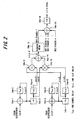
- Fig. 2 is a diagram showing the structure of a fading-pitch detection circuit that employs a pilot signal.
- cos ⁇ represents an I-component of a pilot signal that is output from a despreader
- sin ⁇ represents a Q-component of the pilot signal output from the despreader.
- the base station carries out AFC (Automatic Frequency Control) and, hence, there is no frequency shift in sending and receiving. This means that ⁇ is a phase shift ascribable to fading.
- AFC Automatic Frequency Control
- an adder circuit 54a-1 adds the presently prevailing cos ⁇ and the sum ⁇ cos ⁇ , up to the immediately preceding cos ⁇ , delayed by one symbol by a delay circuit 54a-2.
- An average calculation unit 54a-3 obtains the average value of cos ⁇ over one slot by taking one-sixth of the total value ⁇ cos ⁇ over one slot and outputs cos ⁇ 1 of the present slot, and a delay circuit 54a-4 delays cos ⁇ 1 by one slot and outputs cos ⁇ 2 of the preceding slot.
- An adder circuit 54a-5 adds the presently prevailing sin ⁇ and the sum ⁇ sin ⁇ , up to the immediately preceding sin ⁇ , delayed by one symbol by a delay circuit 54a-6.
- An average calculation unit 54a-7 obtains the average value of sin ⁇ over one slot by taking one-sixth of the total value ⁇ sin ⁇ over one slot and outputs sin ⁇ 1 of the present slot, and a delay circuit 54a-8 delays sin ⁇ 1 by one and outputs sin ⁇ 2 of the preceding slot.
- Multipliers 54a-9, 54a-10 and an adder circuit 54a-11 perform the operation of Equation (4) to calculate sin ⁇
- a running-mean calculation unit 54a-12 calculates the running mean over several slots
- an adder circuit 54a-13 totals the eight running means output from the four fingers / two branches (a total or eight fingers)
- an average calculation unit 54a-14 divides the sum total by eight to calculate sin ⁇ RAKE and output the same as the fading pitch.
- Fig. 3 is a diagram illustrating the relationship among fading pitch, receive SIR and a TPC bit.
- receive SIR in the absence of transmission power control (TPC) receive SIR when transmission power control (TPC) is applied and the direction of transmission power control in units of 1 dB based upon a TPC bit (command) are indicated at (1) to (3).
- Transmission power control is carried out slot by slot.
- An up arrow signifies 1 dB up and a down arrow signifies 1 dB down.
- Fig. 3 (1) illustrates a case where the fluctuation of receive SIR in one slot when transmission power control (TPC) is not being performed is larger than 1 dB, (2) illustrates a case where the fluctuation of receive SIR in one slot when transmission power control (TPC) is not being performed is equal to 1 dB, and (3) illustrates a case where the fluctuation of receive SIR in one slot when transmission power control (TPC) is not being performed is less than 1 dB.
- Receive SIR decreases if fading increases and increases if fading decreases. Accordingly, the change in receive SIR when TPC is not being carried out represents the inverse of the fading characteristic at radio frequency.
- the change in receive SIR and the fluctuation in the direction of transmission power control due to the TPC bits each depend upon the fading pitch. These can therefore be utilized in detection of fading pitch.
- Fig. 4 is a block diagram showing a fading-pitch detection circuit for detecting fading pitch based upon a change in receive SIR.
- This circuit obtains the average value of receive SIR, detects the number of times the receive SIR crosses this average value in a prescribed period of time and adopts this as the fading pitch.
- the SIR measurement unit 52 estimates the SIR of the receive signal
- an integrating/averaging circuit 54b-1 integrates the result of SIR measurement and calculates the average value thereof
- adder circuits 54b-2, 54b-3 add and subtract a margin ⁇ M, which is output from a margin generating circuit 54b-4, to and from the average value and input the results to comparator circuits 54b-5, 54b-6.
- the comparator circuits 54b-5, 54b-6 compare the receive SIR and (average SIR ⁇ ⁇ M) in terms of magnitude and input a high-level comparison result to a timer 54b-7 if the receive SIR is larger and a low-level comparison result to the timer 54b-7 if the receive SIR is smaller.
- the timer 54b-7 construes that the measured SIR has crossed the average value and outputs a count pulse to a counter 54b-8.
- the counter 54b-8 counts the number of times the level is crossed within the fixed period of time.
- the value of the count is the fading pitch.
- a timer 54b-9 resets the value of the count in the counter at the fixed time interval.
- the margin ⁇ M is added to and subtracted from the average SIR. If the measured SIR exceeds both levels (average SIR ⁇ ⁇ M) or falls below both of these levels, it is judged that the average level has been crossed. Accordingly, the counter 54b-8 does not count even if the measured SIR fluctuates in the vicinity of the average value. The counter therefore counts the correct number of crossings and can detect the fading pitch accurately.
- Fig. 5 is a block diagram showing a fading-pitch detection circuit that employs the TPC bit.
- An up/down counter 54c-1 counts up TPC bits in the 1-dB-up direction and counts down TPC bits in the 1-dB-down direction.
- An integrating/averaging circuit 54c-2 integrates the value of the count in up/down counter 54c-1, calculates the average value of the count in counter 54c-1 over a plurality of slots and outputs the average value.
- Adder circuits 54c-3, 54c-4 add and subtract a margin ⁇ M, which is output from a margin generating circuit 54c-5, to and from the average value and input the results to comparator circuits 54c-6, 54c-7.
- the comparator circuits 54c-6, 54c-7 compare the count in the up/down counter 54c-1 and (average SIR ⁇ ⁇ M) in terms of magnitude and input a high-level comparison result to a timer 54c-8 if the count is larger and a low-level comparison result to the timer 54c-8 if the count is smaller.
- the timer 54c-8 construes that the count in the up/down counter 54c-1 has crossed the average value and outputs a count pulse to a counter 54c-9.
- the counter 54c-9 counts the number of times the average level is crossed within the fixed period of time. The value of the count is the fading pitch.
- a timer 54b-9 resets the value of the count in the counter 54c-9 at the fixed time interval.
- the margin ⁇ M is added to and subtracted from the average count. If the counted value exceeds both levels (average count ⁇ ⁇ M) or falls below both of these levels, it is judged that the average level has been crossed. Accordingly, the counter 54c-9 does not count even if the counted value in up/down counter 54c-1 fluctuates in the vicinity of the average value. The counter therefore counts the correct number of crossings and can detect the fading pitch accurately.
- Fig. 6 illustrates a first embodiment of transmission power control for correcting a target SIR by a fading pitch detected using a pilot signal.
- a mobile station 100 includes a spread-spectrum modulator 101 for spread-spectrum modulating transmit data using a spreading code conforming to a prescribed channel specified by a base station, and a power amplifier 102 for amplifying a signal, which is input thereto following processing such as quadrature modulation and frequency conversion applied after spread-spectrum modulation, and transmitting the amplified signal to a base station 200 from an antenna.
- a spread-spectrum modulator 101 for spread-spectrum modulating transmit data using a spreading code conforming to a prescribed channel specified by a base station
- a power amplifier 102 for amplifying a signal, which is input thereto following processing such as quadrature modulation and frequency conversion applied after spread-spectrum modulation, and transmitting the amplified signal to a base station 200 from an antenna.
- the base station 200 subjects the receive signal from the mobile station to a frequency conversion (RF ⁇ IF conversion), quadrature detection and AD conversion processing and inputs the AD-converted output to a despreader 201 of a finger conforming to each path of multiple paths.
- the despreader 201 subjects a delayed signal that arrives via an assigned path to despread processing.
- a RAKE demodulator 202 combines the signals output from the fingers, subjects the combined signal to maximal ratio combining at a weighting conforming to the reception power of each branch, and discriminates "1"s and "0"s of the receive data based upon the maximal-ratio combination signal.
- the correspondence between sin ⁇ RAKE and correction data ⁇ S of the target SIR has been written to a ROM 204 in advance. More specifically, before the apparatus is placed in operation, fading is varied and the correction data ⁇ S of a target SIR for which the desired BER is obtained is found with respect to the fading pitch sin ⁇ RAKE . This is repeated in similar fashion to obtain the correspondence between a large number of values of sin ⁇ RAKE and the correction data ⁇ S and the correspondence is burned into the ROM 204. As a result, when sin ⁇ RAKE enters the ROM 204 from the fading-pitch detection circuit 203, the correspondence correction data ⁇ S is read out of the ROM and is input to a target-ROM correction unit 207.
- SIR power ratio
- Interference interference signal
- a comparator 208 compares the corrected target SIR with the measured SIR, creates a command which lowers the transmission power using a TPC bit if the measured SIR is greater than the target SIR, and creates a command to raise the transmission power using the TPC bit if the measured SIR is less than the target SIR.
- a spread-spectrum modulator 209 spread-spectrum modulates the transmit data and TPC bits. After spread-spectrum modulation, the base station 200 executes processing such as DA conversion, quadrature modulation, frequency conversion and power amplification and transmits the results to the mobile station 100 from an antenna.
- a despreader 103 in the mobile station 100 applies despread processing to the signal received from the base station 200, and a RAKE demodulator 104 demodulates the receive data and TPC bits and controls the transmission power of the power amplifier 102 in accordance with a command specified by the TPC bit.
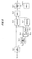
- Fig. 7 illustrates a second embodiment of transmission power control for correcting a target SIR by fading pitch detected using SIR.
- Components identical with those of the first embodiment shown in Fig. 6 are designated by like reference characters. This embodiment differs in that:
- Transmission power control is carried out in a manner similar to that of the first embodiment.
- Fig. 8 illustrates a third embodiment of transmission power control for correcting a target SIR by fading pitch detected using a change in the transmission power control direction of TPC bits.
- Components identical with those of the first embodiment shown in Fig. 6 are designated by like reference characters. This embodiment differs in that:
- Transmission power control is carried out in a manner similar to that of the first embodiment.
- Fig. 9 is a block diagram showing a path detection and path-to-path level difference detection circuit.
- each branch is provided with one searcher 61 that creates a delay profile by performing an autocorrelation operation using a matched filter (not shown), detects multipath based upon the peak levels of the delay profile, and inputs despreading-start timing data and delay-time adjustment data of the respective paths to the fingers. Further, if one branch has four fingers, then the searcher 61 outputs the reception levels of the four paths constituting multipath as a, b, c, d in order of decreasing size.
- the path for which the reception level is maximum is path 1
- the path having the next highest reception level is path 2, and so on for paths 3 and 4.
- Path 1 is referred to as the main path.
- a logarithmic converter 62 subjects the reception level of each path to a truth value ⁇ log conversion in order to execute processing upon providing a threshold value in dB.
- a level-difference calculation unit 63 calculates a level difference A (a'-b') between the main path 1 and path 2
- a level-difference calculation unit 64 calculates a level difference B (b'-c') between path 2 and path 3
- a level-difference calculation unit 65 calculates a level difference C (c'-d') between path 3 and path 4. If the level difference with respect to the main path is 15 dB or greater, then it is considered that there is almost no deterioration in characteristic even if the level difference is regarded as 15 dB.
- the level of the receive signal is lower than a maximum reception level Lmax by 15 dB or more, then the level difference is regarded as 15 dB and the level of the receive signal is made (Lmax - 15).
- this expedient is adopted, 815 combinations of levels A, B, C exist, as shown in Figs. 10 and 11, where Fig. 10 illustrates the initial 43 combinations and Fig. 11 illustrates the final 45 combinations. The combinations are distinguished from one another by addresses 0 to 814.
- a decoder 66 incorporates the decoding table of Figs. 10, 11 and outputs, in a form expressed by ten bits, addresses conforming to the combinations of levels A, B, C that enter from each of the level-difference calculations units 63 to 65. As a result, the decoder can specify the level differences between paths.
- Fig. 12 shows an embodiment of transmission power control for correcting a target SIR by level differences between paths. Components identical with those of the embodiment of Fig. 6 are designated by like reference characters. This embodiment differs from that of Fig. 6 in that transmission power control is performed based upon the level differences between paths and not fading pitch.
- the correspondence between combinations of level differences A, B, C between paths and target-SIR correction data ⁇ S is stored in the ROM 204 beforehand. That is, before the apparatus is placed in operation, the level differences A, B, C between paths are varied, the correction data ⁇ S of a target SIR that make the desired BER possible is obtained and the correction data ⁇ S is stored at the address conforming to each level difference between paths.
- a path level difference detection circuit 221 arranges the reception levels of each of the paths in order of decreasing size, calculates the level differences A, B, C between mutually adjacent reception levels and generates addresses conforming to the combinations of the level differences A, B, C.
- the correction data ⁇ S is read out of the ROM from this address and is input to the target-SIR correction unit 207. Transmission power control similar to that of Fig. 6 is then carried out.
- the embodiments described above relate to cases where transmission power control is performed upon correcting target SIR based on fading pitch and based on level differences between paths. However, it is also possible to adopt an arrangement in which transmission power control is carried out upon correcting target SIR taking both fading pitch and level differences into consideration.
- Fig. 13 illustrates an embodiment in which transmission power control is carried out upon correcting a target SIR taking both fading pitch and level differences between paths into consideration.
- Components identical with those of Figs. 6 and 12 are designated by like reference characters.
- Correction data ⁇ S conforming to combinations of level differences between paths and fading pitch is stored in the ROM 204 beforehand. That is, level differences between paths are varied in accordance with the decoding table of Figs. 10, 11 at a prescribed fading pitch, the correction data ⁇ S of a target SIR that make the desired BER possible is obtained at each level difference between paths, and the correction data ⁇ S is stored at the ROM address conforming to each combination of level differences between paths and fading pitch. Fading pitch and the level differences between paths are varied similarly and correction data ⁇ S is stored at all addresses conforming to combinations of level differences between paths and fading pitch.
- the fading-pitch detection circuit 203 detects fading pitch using the pilot signal. Further, the path level difference detection circuit 221 (see Fig. 9) arranges the reception levels of each of the paths in order of decreasing size, calculates the level differences A, B, C between mutually adjacent reception levels and generates addresses conforming to the combinations of the level differences A, B, C. As a result, the correction data ⁇ S is read out of the ROM 204 from a storage area designated by the fading pitch and an address that corresponds to the level differences between paths, and the correction data is input to the target-SIR correction unit 207. Transmission power control similar to that of Fig. 6 is then carried out.
- fading pitch is detected using the pilot signal.
- fading pitch is detected using receive SIR.
- Fig. 14 is a block diagram of such a modification. This differs from the embodiment of Fig. 13 in that the fading-pitch detection circuit 211 (see Fig. 4) is provided to detect fading pitch based upon receive SIR. Transmission power control is the same as that of the embodiment of Fig. 16.
- fading pitch is detected using the pilot signal.
- fading pitch is detected using a change in the power control direction of TPC bits.
- Fig. 15 is a block diagram of such a modification. This differs from the embodiment of Fig. 13 in that the fading-pitch detection circuit 212 (see Fig. 5) is provided to detect fading pitch based upon a change in the transmission power control direction of TPC bits. Transmission power control is the same as that of the embodiment of Fig. 16.
- Fig. 16 illustrates an embodiment for correcting a target SIR based upon fading pitch, level differences between paths and a difference between measured BER and target BER.
- Components identical with those shown in Fig. 13 are designated by like reference characters. This embodiment differs in that:
- the correction data is initially set in the storage device 204' by a method identical with that of Fig. 13.
- the fading-pitch detection circuit 203 detects fading pitch using the pilot signal and inputs the fading pitch to the storage device 204'.
- the path level difference detection circuit 221 arranges the reception levels of each of the paths in order of decreasing size, calculates the level differences A, B, C between mutually adjacent reception levels and inputs addresses conforming to the combinations of the level differences A, B, C to the storage device 204'.
- the BER estimating circuit 232 estimates the BER that prevails prior to error correction and inputs this BER to the comparator 223.
- the comparator 223 calculates a difference d between the set BER and estimated BER and inputs this difference to the storage device 204'.
- the correction data ⁇ S is read out of the storage device 204' from a storage area designated by a combination of the fading pitch and an address that corresponds to the level differences between paths, the correction data is increased or decreased in value based upon the difference d between set BER and estimated BER, the old data is updated by the correction data after the increase or decrease in value, and the corrected data after updating is input to the target-SIR correction unit 207.
- correction data in the storage device 204' is updated so as to increase the value. If the estimated BER is better than the set BER, correction data in the storage device 204' is updated so as to decrease the value.
- the updated data is input to the target-SIR correction unit 207.
- Fig. 17 illustrates an embodiment of a circuit for estimating BER prevailing prior to error correction.
- the BER estimating circuit 232 estimates the BER prevailing prior to error correction by using the discriminated data (the data prior to the error correction).
- a decoder 71 performs decoding while applying error-correction processing to the RAKE-demodulated data (the data prior to error correction)
- an encoder 72 performs encoding while adding an error-detection code onto the decoded data.
- a delay unit 73 delays the input data for a period of time needed for decoding and encoding processing, and a comparator 74 compares the data prior to the error correction output from the delay unit 73 and the encoded data output from the encoder 72. Correctable error is corrected by the decoding processing of decoder 71 and error-free encoded data ideally is output from the encoder 72. Accordingly, error data contained in the data prevailing prior to error correction is detected from the comparator 74, and a counter 75 counts error data generated within a prescribed period of time and outputs the value of the count as BER prior to error correction. A timer 76 resets the value of the count of counter 75 at the prescribed time interval.
- fading pitch is detected using the pilot signal.
- fading pitch is detected using receive SIR.
- Fig. 18 is a block diagram of such a modification. This differs from the embodiment of Fig. 16 in that the fading-pitch detection circuit 211 (see Fig. 4) is provided to detect fading pitch based upon receive SIR. Transmission power control is the same as that of the embodiment of Fig. 16.
- fading pitch is detected using the pilot signal.
- fading pitch is detected using a change in the power control direction of TPC bits.
- Fig. 19 is a block diagram of such a modification. This differs from the embodiment of Fig. 16 in that the fading-pitch detection circuit 212 (see Fig. 5) is provided to detect fading pitch based upon a change in the transmission power control direction of TPC bits. Transmission power control is the same as that of the embodiment of Fig. 16.
- Fig. 20 illustrates an embodiment for correcting a target SIR based upon fading pitch, level differences between paths and a difference between measured FER and target FER.
- Components identical with those shown in Fig. 13 are designated by like reference characters.
- the correction data is initially set in the storage device 204' by a method identical with that of Fig. 13.
- the fading-pitch detection circuit 203 detects fading pitch using the pilot signal and inputs the fading pitch to the storage device 204'.
- the path level difference detection circuit 221 arranges the reception levels of each of the paths in order of decreasing size, calculates the level differences A, B, C between mutually adjacent reception levels and inputs addresses conforming to the combinations of the level differences A, B, C to the storage device 204'.
- the FER estimating circuit 242 estimates the FER that prevails after error correction and inputs this FER to the comparator 243.
- the comparator 243 calculates a difference d between the set FER and estimated FER and inputs this difference to the storage device 204'.
- the correction data ⁇ S is read out of the storage device 204' from a storage area designated by a combination of the fading pitch and an address that corresponds to the level differences between paths, the correction data is increased or decreased in value based upon the difference d between set FER and estimated FER, the old data is updated by the correction data after the increase or decrease in value, and the corrected data after updating is input to the target-SIR correction unit 207.
- correction data in the storage device 204' is updated so as to increase the value. If the estimated FER is better than the set FER, correction data in the storage device 204' is updated so as to decrease the value. The updated data is input to the target-SIR correction unit 207.
- Fig. 21 illustrates an embodiment of a circuit for estimating FER prevailing after error correction.
- This circuit uses a CRC check to find the FER.
- a CRC check is such that when division is performed by a prescribed generating polynomial on the receiving side, a redundant bit is added on frame by frame on the transmitting side in such a manner that the remainder will become zero. Accordingly, if the result of division on the receiving side is that the remainder is zero, the frame will be free of error; if there is a remainder, then the frame contains an error.
- the generating polynomial in this FER estimating circuit is assumed to be 1+X+X 4 , for example, and the contents of shift registers D 1 to D 4 after all input signals have eventually been input to the FER estimating circuit are remainders. Accordingly, if there is even one logical sum of all of the remainders, then this means that the frame contains an error. By counting this value, the estimated value of FER can be detected.
- the FER estimating circuit of Fig. 21 includes flip-flops D 1 to D 4 constructing a shift register, exclusive-OR circuits EXO1, EXO2, flip-flops FF 1 to FF 4 in which the contents of the shift registers are set in sync with the frame pulses, an OR gate OR for taking the logical sum of the flip-flop and outputting a frame-error signal, a counter CNT for counting a high-level frame-error signal output from the OR gate, and a timer TMR for resetting the content of the counter at prescribed time intervals.
- fading pitch is detected using the pilot signal.
- fading pitch is detected using receive SIR.
- Fig. 22 is a block diagram of such a modification. This differs from the embodiment of Fig. 20 in that the fading-pitch detection circuit 211 (see Fig. 4) is provided to detect fading pitch based upon receive SIR. Transmission power control is the same as that of the embodiment of Fig. 20.
- fading pitch is detected using the pilot signal.
- fading pitch is detected using a change in the power control direction of TPC bits.
- Fig. 15 is a block diagram of such a modification. This differs from the embodiment of Fig. 20 in that the fading-pitch detection circuit 212 (see Fig. 5) is provided to detect fading pitch based upon a change in the transmission power control direction of TPC bits. Transmission power control is the same as that of the embodiment of Fig. 16.
- the desired BER can be maintained by enlarging target SIR.
- the desired BER can be maintained by changing the target SIR.
- the desired BER can be maintained even if rate of change in fading and a level difference between signals that arrive via the paths of multiple paths vary simultaneously.
- bit error rate BER is measured, the target SIR is corrected based upon the difference between the measured BER and a target BER and the transmission power of the mobile station is controlled in such a manner that the measured SIR will agree with the corrected target SIR.
- the desired BER can be obtained with a higher degree of precision.
- frame error rate FER is measured, the target SIR is corrected based upon the difference between the measured FER and a target FER and the transmission power of the mobile station is controlled in such a manner that the measured SIR will agree with the corrected target SIR.
- the desired BER can be obtained with a higher degree of precision.
Landscapes
- Engineering & Computer Science (AREA)
- Computer Networks & Wireless Communication (AREA)
- Signal Processing (AREA)
- Mobile Radio Communication Systems (AREA)
Abstract
Description

Claims (12)
- A transmission power control apparatus in a base station for measuring SIR, which is a ratio of a receive signal to an interference signal, and controlling transmission power of a mobile station in such a manner that said measured SIR will agree with a target SIR, comprising:a fading detector for detecting rate of change in fading;a correction unit for correcting the target SIR based upon the rate of change in fading; andmeans for creating a command, which controls transmission power of the mobile station in such a manner that the measured SIR will agree with said corrected target SIR, and transmitting this command to the mobile station.
- A transmission power control apparatus according to claim 1, further comprising a memory for storing correspondence between rates of change in fading and correction values of target SIR, wherein said correction unit corrects the target SIR using a correction value corresponding to the rate of change in fading read out of the memory.
- A transmission power control apparatus in a base station for measuring SIR, which is a ratio of a receive signal to an interference signal, and controlling transmission power of a mobile station in such a manner that said measured SIR will agree with a target SIR, comprising:a searcher for detecting multipath and levels of signals that arrive via respective ones of the paths;a level-difference calculation unit for calculating level differences between paths using the levels of signals;a correction unit for correcting the target SIR based upon the level differences between paths; andmeans for creating a command, which controls transmission power of the mobile station in such a manner that the measured SIR will agree with said corrected target SIR, and transmitting this command to the mobile station.
- A transmission power control apparatus according to claim 3, further comprising a memory for rounding, as (Lmax - Ls), levels for which the level difference from a maximum level Lmax is less than a set value Ls, and storing correction values of target SIR in correspondence with combinations of level differences between mutually adjacent reception levels in the order of the reception levels;
wherein said level-difference calculation unit arranges the reception levels of each of the paths of the multiple paths in order of decreasing or increasing size and calculates level differences between mutually adjacent reception levels; and
said correction unit corrects the target SIR using a correction value corresponding to the combination of level differences read out of the memory. - A transmission power control apparatus in a base station for measuring SIR, which is a ratio of a receive signal to an interference signal, and controlling transmission power of a mobile station in such a manner that said measured SIR will agree with a target SIR, comprising:a fading detector for detecting rate of change in fading;a searcher for detecting multipath and levels of signals that arrive via respective ones of the paths;a level-difference calculation unit for calculating level differences between paths using the levels of signals;a correction unit for correcting the target SIR based upon a combination of the rate of change in fading and the level differences between paths; andmeans for creating a command, which controls transmission power of the mobile station in such a manner that the measured SIR will agree with said corrected target SIR, and transmitting this command to the mobile station.
- A transmission power control apparatus in a base station for measuring SIR, which is a ratio of a receive signal to an interference signal, and controlling transmission power of a mobile station in such a manner that said measured SIR will agree with a target SIR, comprising:a fading detector for detecting rate of change in fading;a searcher for detecting multipath and levels of signals that arrive via respective ones of the paths;a level-difference calculation unit for calculating level differences between paths using the levels of signals;a BER measurement unit for measuring bit-error rate BER;a correction unit for correcting the target SIR based upon a combination of the rate of change in fading, the level differences between paths and a difference between measured BER and target BER; andmeans for creating a command, which controls transmission power of the mobile station in such a manner that the measured SIR will agree with said corrected target SIR, and transmitting this command to the mobile station.
- A transmission power control apparatus according to claim 6, further comprising a memory for storing correction values of target SIR in correspondence with combinations of rate change in fading and level differences between paths;
wherein said correction unit corrects a correction value, which corresponds to a combination of the rate of change in fading and the level differences between paths read out of the memory, on the basis of the difference between measured BER and target BER, and corrects the target SIR by said correction value. - A transmission power control apparatus in a base station for measuring SIR, which is a ratio of a receive signal to an interference signal, and controlling transmission power of a mobile station in such a manner that said measured SIR will agree with a target SIR, comprising:a fading detector for detecting rate of change in fading;a searcher for detecting multipath and levels of signals that arrive via respective ones of the paths;a level-difference calculation unit for calculating level differences between paths using the levels of signals;a FER measurement unit for measuring frame-error rate FER;a correction unit for correcting the target SIR based upon a combination of the rate of change in fading and the level differences between paths and a difference between the measured FER and target FER; andmeans for creating a command, which controls transmission power of the mobile station in such a manner that the measured SIR will agree with said corrected target SIR, and transmitting this command to the mobile station.
- A transmission power control apparatus according to claim 8, further comprising a memory for storing correction values of target SIR in correspondence with combinations of rate change in fading and level differences between paths;
wherein said correction unit corrects a correction value, which corresponds to a combination of the rate of change in fading and the level differences between the paths read out of the memory, on the basis of the difference between the measured FER and the target FER, and corrects target SIR by said correction value. - A transmission power control apparatus according to claim 1, 5, 6 or 8, characterized in that said fading detector detects the rate of change in fading from a difference between phase of a pilot signal, which has been received from the mobile station before a prescribed time in the past and phase of the pilot signal at the present time.
- A transmission power control apparatus according to claim 1, 5, 6 or 8, characterized in that said fading detector detects the rate of change in fading based upon the measured SIR.
- A transmission power control apparatus according to claim 1, 5, 6 or 8, characterized in that said fading detector detects the rate of change in fading based upon direction of transmission power control by TPC bits.
Applications Claiming Priority (1)
| Application Number | Priority Date | Filing Date | Title |
|---|---|---|---|
| PCT/JP1999/005183 WO2001022756A1 (en) | 1999-09-22 | 1999-09-22 | Transmission power controller |
Publications (3)
| Publication Number | Publication Date |
|---|---|
| EP1215926A1 true EP1215926A1 (en) | 2002-06-19 |
| EP1215926A4 EP1215926A4 (en) | 2004-01-28 |
| EP1215926B1 EP1215926B1 (en) | 2006-06-21 |
Family
ID=14236777
Family Applications (1)
| Application Number | Title | Priority Date | Filing Date |
|---|---|---|---|
| EP99944777A Expired - Lifetime EP1215926B1 (en) | 1999-09-22 | 1999-09-22 | Transmission power controller |
Country Status (5)
| Country | Link |
|---|---|
| US (1) | US7062287B2 (en) |
| EP (1) | EP1215926B1 (en) |
| JP (1) | JP3961828B2 (en) |
| DE (1) | DE69932102T2 (en) |
| WO (1) | WO2001022756A1 (en) |
Cited By (11)
| Publication number | Priority date | Publication date | Assignee | Title |
|---|---|---|---|---|
| WO2003017526A1 (en) * | 2001-08-10 | 2003-02-27 | Qualcomm Incorporated | Method and apparatus for controlling gain level of a communication channel in a cdma communication system |
| EP1548956A1 (en) * | 2003-11-26 | 2005-06-29 | Nec Corporation | Reduction of power consumption and interference power in outer loop transmit power control system |
| WO2006082881A1 (en) | 2005-02-02 | 2006-08-10 | Nec Corporation | Transmission power target value variable control apparatus and method and mobile communication terminal |
| WO2008060023A1 (en) * | 2006-11-16 | 2008-05-22 | Electronics And Telecommunications Research Institute | Transceiver and transceiving method in uwb system for frequency sharing |
| EP1635483A4 (en) * | 2003-06-19 | 2010-05-05 | Fujitsu Ltd | METHOD AND DEVICE FOR ADJUSTING TRANSMISSION POWER |
| US7899482B2 (en) | 2005-02-02 | 2011-03-01 | Nec Corporation | Transmission power target value variable control apparatus and method and mobile communication terminal |
| EP2367384A1 (en) * | 2010-03-05 | 2011-09-21 | Fujitsu Limited | Mobile terminal and power control method taking into account communication environment for threshold adjustment |
| US8442444B2 (en) | 2007-12-27 | 2013-05-14 | Fujitsu Limited | Method of transmit power control and device thereof |
| EP3041297A4 (en) * | 2013-09-27 | 2016-09-14 | Huawei Tech Co Ltd | METHOD AND DEVICE FOR ADJUSTING TRANSMISSION POWER |
| US9655062B2 (en) | 2001-06-13 | 2017-05-16 | Ipr Licensing, Inc. | System and method for coordination of wireless maintenance channel power control |
| US9661593B2 (en) | 2002-10-17 | 2017-05-23 | Interdigital Technology Corporation | Power control for communications systems utilizing high speed shared channels |
Families Citing this family (36)
| Publication number | Priority date | Publication date | Assignee | Title |
|---|---|---|---|---|
| US6977967B1 (en) * | 1995-03-31 | 2005-12-20 | Qualcomm Incorporated | Method and apparatus for performing fast power control in a mobile communication system |
| TW347616B (en) * | 1995-03-31 | 1998-12-11 | Qualcomm Inc | Method and apparatus for performing fast power control in a mobile communication system a method and apparatus for controlling transmission power in a mobile communication system is disclosed. |
| JP3621310B2 (en) * | 1999-10-07 | 2005-02-16 | 松下電器産業株式会社 | Wireless communication apparatus and transmission power control method |
| FI112743B (en) * | 1999-10-20 | 2003-12-31 | Nokia Corp | Method and arrangement for controlling transmitter power and a network element |
| KR100386562B1 (en) * | 1999-11-01 | 2003-06-02 | 엘지전자 주식회사 | Method for power control of Forward Common Channel |
| JP3424647B2 (en) * | 2000-04-04 | 2003-07-07 | 日本電気株式会社 | CDMA transceiver |
| JP2001345755A (en) * | 2000-05-31 | 2001-12-14 | Toshiba Corp | Wireless communication system and wireless device |
| EP1353456B1 (en) * | 2001-01-17 | 2016-04-20 | Fujitsu Limited | Outer loop power control device and method |
| US8199696B2 (en) * | 2001-03-29 | 2012-06-12 | Qualcomm Incorporated | Method and apparatus for power control in a wireless communication system |
| US7751843B2 (en) * | 2002-07-29 | 2010-07-06 | Qualcomm Incorporated | Reducing interference with a multiple format channel in a communication system |
| AU2003259306A1 (en) * | 2002-07-31 | 2004-02-16 | Interdigital Technology Corporation | Equalizing signal-to-interference ratios of different physical channels supporting a coded composite transport channel |
| US6985727B2 (en) * | 2002-09-12 | 2006-01-10 | Qualcomm Incorporated | Method and apparatus for optimizing search rate and finger assignment rate |
| US7184791B2 (en) * | 2002-09-23 | 2007-02-27 | Telefonaktiebolaget Lm Ericsson (Publ) | Methods, receivers, and computer program products for determining transmission power control commands using biased interpretation |
| US7254158B2 (en) | 2003-05-12 | 2007-08-07 | Qualcomm Incorporated | Soft handoff with interference cancellation in a wireless frequency hopping communication system |
| US7054391B2 (en) * | 2003-05-30 | 2006-05-30 | Efficient Channel Coding, Inc. | Receiver based saturation estimator |
| US7925291B2 (en) * | 2003-08-13 | 2011-04-12 | Qualcomm Incorporated | User specific downlink power control channel Q-bit |
| JP3800222B2 (en) | 2004-02-19 | 2006-07-26 | 日本電気株式会社 | Target value control system and method for transmission power control, base station and portable communication terminal |
| JP4628150B2 (en) * | 2004-03-29 | 2011-02-09 | パナソニック株式会社 | Communication apparatus and communication method |
| JP4445876B2 (en) * | 2005-01-14 | 2010-04-07 | 株式会社エヌ・ティ・ティ・ドコモ | Radio quality estimation system, base station, mobile station, and radio quality estimation method |
| US20060252451A1 (en) * | 2005-05-06 | 2006-11-09 | Cho Sung R | Transmission power control device and method |
| JP4969807B2 (en) * | 2005-07-01 | 2012-07-04 | 京セラ株式会社 | Wireless communication system, wireless communication terminal device, relay device, and wireless communication method |
| WO2007077667A1 (en) * | 2006-01-04 | 2007-07-12 | Nec Corporation | Wireless communication system, wireless base station, wireless terminal station and transmission power control method using such system and stations |
| JP4589249B2 (en) | 2006-02-21 | 2010-12-01 | 富士通株式会社 | Power control apparatus in wireless communication system |
| US7835468B2 (en) * | 2006-03-13 | 2010-11-16 | Silicon Laboratories, Inc. | Impulse detection and reduction in a frequency modulation radio receiver |
| JP4772605B2 (en) * | 2006-06-30 | 2011-09-14 | 富士通株式会社 | Wireless communication apparatus and transmission power control method |
| JP4769698B2 (en) * | 2006-11-30 | 2011-09-07 | 富士通株式会社 | Interference power estimation apparatus and interference power estimation method |
| US8886245B2 (en) * | 2007-03-09 | 2014-11-11 | Qualcomm Incorporated | Messaging scheme for controlling uplink transmit power of a wireless device |
| JP5173490B2 (en) * | 2008-02-28 | 2013-04-03 | 独立行政法人情報通信研究機構 | Sensitivity degradation estimation system and sensitivity degradation estimation method |
| US8477830B2 (en) | 2008-03-18 | 2013-07-02 | On-Ramp Wireless, Inc. | Light monitoring system using a random phase multiple access system |
| US8958460B2 (en) | 2008-03-18 | 2015-02-17 | On-Ramp Wireless, Inc. | Forward error correction media access control system |
| US8520721B2 (en) | 2008-03-18 | 2013-08-27 | On-Ramp Wireless, Inc. | RSSI measurement mechanism in the presence of pulsed jammers |
| US20100195553A1 (en) | 2008-03-18 | 2010-08-05 | Myers Theodore J | Controlling power in a spread spectrum system |
| WO2009155006A2 (en) * | 2008-05-27 | 2009-12-23 | Viasat, Inc . | Fault tolerant modem redundancy |
| US8363699B2 (en) | 2009-03-20 | 2013-01-29 | On-Ramp Wireless, Inc. | Random timing offset determination |
| JP5603647B2 (en) * | 2009-05-13 | 2014-10-08 | キヤノン株式会社 | Power feeding device, power feeding device control method, and power feeding communication system |
| WO2015163013A1 (en) * | 2014-04-25 | 2015-10-29 | ソニー株式会社 | Wireless communication device, wireless communication method, and wireless communication system |
Family Cites Families (25)
| Publication number | Priority date | Publication date | Assignee | Title |
|---|---|---|---|---|
| JPH0681087B2 (en) | 1987-07-29 | 1994-10-12 | 三菱電機株式会社 | Transmission output control device |
| WO1994018756A1 (en) * | 1993-02-11 | 1994-08-18 | Motorola, Inc. | Method and apparatus for controlling a power level of a subscriber unit of a wireless communication system |
| US5802110A (en) * | 1994-02-16 | 1998-09-01 | Matsushita Electric Industrial Co., Ltd. | Wireless mobile system |
| JPH07231278A (en) | 1994-02-18 | 1995-08-29 | Fujitsu Ltd | Rake receiver using direct sequence spread spectrum communication |
| JP2974274B2 (en) * | 1994-05-12 | 1999-11-10 | エヌ・ティ・ティ移動通信網株式会社 | Transmission power control method and transmission power control device |
| JP3380036B2 (en) * | 1994-05-20 | 2003-02-24 | 富士通株式会社 | Standby control method in base station and mobile station |
| JPH0818653A (en) | 1994-06-29 | 1996-01-19 | Kyocera Corp | Telephone |
| JPH0835898A (en) | 1994-07-25 | 1996-02-06 | Hitachi Ltd | Method of adjusting temperature characteristics of semiconductor pressure sensor |
| JP3014308B2 (en) * | 1994-10-24 | 2000-02-28 | エヌ・ティ・ティ移動通信網株式会社 | Transmission power control method in mobile communication system |
| US5873028A (en) * | 1994-10-24 | 1999-02-16 | Ntt Mobile Communications Network Inc. | Transmission power control apparatus and method in a mobile communication system |
| JP2982856B2 (en) | 1994-10-26 | 1999-11-29 | エヌ・ティ・ティ移動通信網株式会社 | Transmission power control method and communication device using the transmission power control method |
| JP2605648B2 (en) | 1994-12-22 | 1997-04-30 | 日本電気株式会社 | Despreading code phase detector for SS receiver |
| TW347616B (en) * | 1995-03-31 | 1998-12-11 | Qualcomm Inc | Method and apparatus for performing fast power control in a mobile communication system a method and apparatus for controlling transmission power in a mobile communication system is disclosed. |
| AU3260195A (en) * | 1995-08-31 | 1997-03-19 | Nokia Telecommunications Oy | Method and device for controlling transmission power of a radio transmitter in a cellular communication system |
| JP3576676B2 (en) | 1996-01-31 | 2004-10-13 | 三菱電機株式会社 | Diversity receiver |
| WO1997050197A1 (en) * | 1996-06-27 | 1997-12-31 | Ntt Mobile Communications Network Inc. | Transmitted power controller |
| JPH1022885A (en) | 1996-07-09 | 1998-01-23 | Oki Electric Ind Co Ltd | Space-time equalizing method |
| JPH1079701A (en) | 1996-09-03 | 1998-03-24 | Fujitsu Ltd | Mobile communication terminal and transmission power control method thereof |
| JP2924864B2 (en) | 1997-06-16 | 1999-07-26 | 日本電気株式会社 | Adaptive rake reception method |
| JP3862111B2 (en) | 1997-08-05 | 2006-12-27 | ソニー株式会社 | Reception device, radio communication system, and communication method |
| JP3159378B2 (en) | 1997-08-13 | 2001-04-23 | 日本電気株式会社 | Spread spectrum communication system |
| JPH1168647A (en) | 1997-08-19 | 1999-03-09 | Matsushita Electric Ind Co Ltd | Diversity receiver |
| JP3805520B2 (en) | 1998-01-28 | 2006-08-02 | 富士通株式会社 | Speed estimation apparatus and method in mobile communication |
| JP3913879B2 (en) | 1998-02-03 | 2007-05-09 | 富士通株式会社 | Communication control apparatus and method based on moving speed |
| US6377813B1 (en) * | 1998-12-03 | 2002-04-23 | Nokia Corporation | Forward link closed loop power control for a third generation wideband CDMA system |
-
1999
- 1999-09-22 DE DE1999632102 patent/DE69932102T2/en not_active Expired - Lifetime
- 1999-09-22 EP EP99944777A patent/EP1215926B1/en not_active Expired - Lifetime
- 1999-09-22 JP JP2001525987A patent/JP3961828B2/en not_active Expired - Fee Related
- 1999-09-22 WO PCT/JP1999/005183 patent/WO2001022756A1/en not_active Ceased
-
2002
- 2002-02-08 US US10/072,058 patent/US7062287B2/en not_active Expired - Fee Related
Cited By (19)
| Publication number | Priority date | Publication date | Assignee | Title |
|---|---|---|---|---|
| US10299218B2 (en) | 2001-06-13 | 2019-05-21 | Ipr Licensing, Inc. | System and method for coordination of wireless maintenance channel power control |
| US9655062B2 (en) | 2001-06-13 | 2017-05-16 | Ipr Licensing, Inc. | System and method for coordination of wireless maintenance channel power control |
| WO2003017526A1 (en) * | 2001-08-10 | 2003-02-27 | Qualcomm Incorporated | Method and apparatus for controlling gain level of a communication channel in a cdma communication system |
| KR100952862B1 (en) * | 2001-08-10 | 2010-04-13 | 퀄컴 인코포레이티드 | Method and apparatus for controlling gain level of communication channel in CDMA communication system |
| US10492154B2 (en) | 2002-10-17 | 2019-11-26 | Interdigital Technology Corporation | Power control for communications systems utilizing high speed shared channels |
| US9661593B2 (en) | 2002-10-17 | 2017-05-23 | Interdigital Technology Corporation | Power control for communications systems utilizing high speed shared channels |
| EP1635483A4 (en) * | 2003-06-19 | 2010-05-05 | Fujitsu Ltd | METHOD AND DEVICE FOR ADJUSTING TRANSMISSION POWER |
| US7778656B2 (en) | 2003-06-19 | 2010-08-17 | Fujitsu Limited | Transmission power control method and apparatus |
| CN100352180C (en) * | 2003-11-26 | 2007-11-28 | 日本电气株式会社 | Reduction of power consumption and interference power in transmit power control system |
| EP1548956A1 (en) * | 2003-11-26 | 2005-06-29 | Nec Corporation | Reduction of power consumption and interference power in outer loop transmit power control system |
| US7899482B2 (en) | 2005-02-02 | 2011-03-01 | Nec Corporation | Transmission power target value variable control apparatus and method and mobile communication terminal |
| EP1845639A4 (en) * | 2005-02-02 | 2010-09-08 | Nec Corp | Transmission power target value variable control apparatus and method and mobile communication terminal |
| US8155690B2 (en) | 2005-02-02 | 2012-04-10 | Nec Corporation | Transmission power target value variable control apparatus and method and mobile communication terminal |
| WO2006082881A1 (en) | 2005-02-02 | 2006-08-10 | Nec Corporation | Transmission power target value variable control apparatus and method and mobile communication terminal |
| WO2008060023A1 (en) * | 2006-11-16 | 2008-05-22 | Electronics And Telecommunications Research Institute | Transceiver and transceiving method in uwb system for frequency sharing |
| US8442444B2 (en) | 2007-12-27 | 2013-05-14 | Fujitsu Limited | Method of transmit power control and device thereof |
| US8463311B2 (en) | 2010-03-05 | 2013-06-11 | Fujitsu Limited | Mobile terminal and power control method |
| EP2367384A1 (en) * | 2010-03-05 | 2011-09-21 | Fujitsu Limited | Mobile terminal and power control method taking into account communication environment for threshold adjustment |
| EP3041297A4 (en) * | 2013-09-27 | 2016-09-14 | Huawei Tech Co Ltd | METHOD AND DEVICE FOR ADJUSTING TRANSMISSION POWER |
Also Published As
| Publication number | Publication date |
|---|---|
| EP1215926B1 (en) | 2006-06-21 |
| JP3961828B2 (en) | 2007-08-22 |
| US7062287B2 (en) | 2006-06-13 |
| US20020094836A1 (en) | 2002-07-18 |
| DE69932102D1 (en) | 2006-08-03 |
| EP1215926A4 (en) | 2004-01-28 |
| DE69932102T2 (en) | 2007-01-11 |
| WO2001022756A1 (en) | 2001-03-29 |
Similar Documents
| Publication | Publication Date | Title |
|---|---|---|
| EP1215926B1 (en) | Transmission power controller | |
| US7103029B1 (en) | Transmitter gain stabilizing apparatus | |
| EP1186116B1 (en) | Method and apparatus for processing a punctured pilot channel | |
| US6377607B1 (en) | System and method for performing accurate demodulation of turbo-encoded signals via pilot assisted coherent demodulation | |
| CA2227162C (en) | Cellular mobile telephone system | |
| US8285318B2 (en) | Method and apparatus for controlling transmission power while in soft handoff | |
| JPWO2001022756A1 (en) | Transmission power control device | |
| CA2278299C (en) | Channel estimating apparatus, and cdma receiver and cdma transceiver each having the apparatus | |
| US6507603B1 (en) | CDMA receiver | |
| US6717976B1 (en) | Method and apparatus for signal to noise power ratio estimation in a multi sub-channel CDMA receiver | |
| US6920173B2 (en) | Spread-spectrum signal receiver apparatus and interference cancellation apparatus | |
| JPH10190497A (en) | SIR measurement device | |
| KR20020073561A (en) | Radio infrared apparatus | |
| JP2004179990A (en) | Radio base station apparatus, decoding apparatus using TFCI decoding characteristic used therefor, and decoding method therefor | |
| US6501789B2 (en) | CDMA receiving apparatus | |
| EP1460777B1 (en) | CDMA reception apparatus and received signal power measuring apparatus in CDMA mobile communication system | |
| US7020183B2 (en) | Code division multiple access signal receiving apparatus | |
| EP0924875B1 (en) | Diversity reception method and apparatus in a CDMA system | |
| EP1405437A1 (en) | Estimating eb/nt in a cdma system using power control bits | |
| EP1111830A1 (en) | Method and apparatus for wireless reception | |
| JP2005328355A (en) | Communication equipment | |
| JP3602509B2 (en) | Demodulation device and demodulation method | |
| JP2007189672A (en) | Channel estimation device | |
| EP1536570A1 (en) | Code division multiple access signal receiving apparatus |
Legal Events
| Date | Code | Title | Description |
|---|---|---|---|
| PUAI | Public reference made under article 153(3) epc to a published international application that has entered the european phase |
Free format text: ORIGINAL CODE: 0009012 |
|
| 17P | Request for examination filed |
Effective date: 20020211 |
|
| AK | Designated contracting states |
Kind code of ref document: A1 Designated state(s): AT BE CH CY DE DK ES FI FR GB GR IE IT LI LU MC NL PT SE |
|
| A4 | Supplementary search report drawn up and despatched |
Effective date: 20031217 |
|
| RIC1 | Information provided on ipc code assigned before grant |
Ipc: 7H 04B 7/005 A |
|
| RA4 | Supplementary search report drawn up and despatched (corrected) |
Effective date: 20031217 |
|
| RBV | Designated contracting states (corrected) |
Designated state(s): DE FR GB |
|
| 17Q | First examination report despatched |
Effective date: 20040618 |
|
| GRAP | Despatch of communication of intention to grant a patent |
Free format text: ORIGINAL CODE: EPIDOSNIGR1 |
|
| GRAS | Grant fee paid |
Free format text: ORIGINAL CODE: EPIDOSNIGR3 |
|
| GRAA | (expected) grant |
Free format text: ORIGINAL CODE: 0009210 |
|
| AK | Designated contracting states |
Kind code of ref document: B1 Designated state(s): DE FR GB |
|
| REG | Reference to a national code |
Ref country code: GB Ref legal event code: FG4D |
|
| REF | Corresponds to: |
Ref document number: 69932102 Country of ref document: DE Date of ref document: 20060803 Kind code of ref document: P |
|
| ET | Fr: translation filed | ||
| PLBE | No opposition filed within time limit |
Free format text: ORIGINAL CODE: 0009261 |
|
| STAA | Information on the status of an ep patent application or granted ep patent |
Free format text: STATUS: NO OPPOSITION FILED WITHIN TIME LIMIT |
|
| 26N | No opposition filed |
Effective date: 20070322 |
|
| REG | Reference to a national code |
Ref country code: FR Ref legal event code: PLFP Year of fee payment: 17 |
|
| PGFP | Annual fee paid to national office [announced via postgrant information from national office to epo] |
Ref country code: DE Payment date: 20150916 Year of fee payment: 17 Ref country code: GB Payment date: 20150916 Year of fee payment: 17 |
|
| PGFP | Annual fee paid to national office [announced via postgrant information from national office to epo] |
Ref country code: FR Payment date: 20150811 Year of fee payment: 17 |
|
| REG | Reference to a national code |
Ref country code: DE Ref legal event code: R119 Ref document number: 69932102 Country of ref document: DE |
|
| GBPC | Gb: european patent ceased through non-payment of renewal fee |
Effective date: 20160922 |
|
| REG | Reference to a national code |
Ref country code: FR Ref legal event code: ST Effective date: 20170531 |
|
| PG25 | Lapsed in a contracting state [announced via postgrant information from national office to epo] |
Ref country code: FR Free format text: LAPSE BECAUSE OF NON-PAYMENT OF DUE FEES Effective date: 20160930 Ref country code: DE Free format text: LAPSE BECAUSE OF NON-PAYMENT OF DUE FEES Effective date: 20170401 Ref country code: GB Free format text: LAPSE BECAUSE OF NON-PAYMENT OF DUE FEES Effective date: 20160922 |