EP1139289B1 - Improved vector quantization - Google Patents
Improved vector quantization Download PDFInfo
- Publication number
- EP1139289B1 EP1139289B1 EP01110017A EP01110017A EP1139289B1 EP 1139289 B1 EP1139289 B1 EP 1139289B1 EP 01110017 A EP01110017 A EP 01110017A EP 01110017 A EP01110017 A EP 01110017A EP 1139289 B1 EP1139289 B1 EP 1139289B1
- Authority
- EP
- European Patent Office
- Prior art keywords
- codebook
- blocks
- image
- subsampled
- block
- Prior art date
- Legal status (The legal status is an assumption and is not a legal conclusion. Google has not performed a legal analysis and makes no representation as to the accuracy of the status listed.)
- Expired - Lifetime
Links
Images


Classifications
-
- H—ELECTRICITY
- H04—ELECTRIC COMMUNICATION TECHNIQUE
- H04N—PICTORIAL COMMUNICATION, e.g. TELEVISION
- H04N7/00—Television systems
- H04N7/24—Systems for the transmission of television signals using pulse code modulation
- H04N7/52—Systems for transmission of a pulse code modulated video signal with one or more other pulse code modulated signals, e.g. an audio signal or a synchronizing signal
- H04N7/54—Systems for transmission of a pulse code modulated video signal with one or more other pulse code modulated signals, e.g. an audio signal or a synchronizing signal the signals being synchronous
-
- G—PHYSICS
- G06—COMPUTING OR CALCULATING; COUNTING
- G06T—IMAGE DATA PROCESSING OR GENERATION, IN GENERAL
- G06T9/00—Image coding
- G06T9/008—Vector quantisation
-
- H—ELECTRICITY
- H04—ELECTRIC COMMUNICATION TECHNIQUE
- H04N—PICTORIAL COMMUNICATION, e.g. TELEVISION
- H04N19/00—Methods or arrangements for coding, decoding, compressing or decompressing digital video signals
- H04N19/10—Methods or arrangements for coding, decoding, compressing or decompressing digital video signals using adaptive coding
- H04N19/134—Methods or arrangements for coding, decoding, compressing or decompressing digital video signals using adaptive coding characterised by the element, parameter or criterion affecting or controlling the adaptive coding
- H04N19/146—Data rate or code amount at the encoder output
- H04N19/149—Data rate or code amount at the encoder output by estimating the code amount by means of a model, e.g. mathematical model or statistical model
-
- H—ELECTRICITY
- H04—ELECTRIC COMMUNICATION TECHNIQUE
- H04N—PICTORIAL COMMUNICATION, e.g. TELEVISION
- H04N19/00—Methods or arrangements for coding, decoding, compressing or decompressing digital video signals
- H04N19/10—Methods or arrangements for coding, decoding, compressing or decompressing digital video signals using adaptive coding
- H04N19/134—Methods or arrangements for coding, decoding, compressing or decompressing digital video signals using adaptive coding characterised by the element, parameter or criterion affecting or controlling the adaptive coding
- H04N19/154—Measured or subjectively estimated visual quality after decoding, e.g. measurement of distortion
-
- H—ELECTRICITY
- H04—ELECTRIC COMMUNICATION TECHNIQUE
- H04N—PICTORIAL COMMUNICATION, e.g. TELEVISION
- H04N19/00—Methods or arrangements for coding, decoding, compressing or decompressing digital video signals
- H04N19/10—Methods or arrangements for coding, decoding, compressing or decompressing digital video signals using adaptive coding
- H04N19/169—Methods or arrangements for coding, decoding, compressing or decompressing digital video signals using adaptive coding characterised by the coding unit, i.e. the structural portion or semantic portion of the video signal being the object or the subject of the adaptive coding
- H04N19/186—Methods or arrangements for coding, decoding, compressing or decompressing digital video signals using adaptive coding characterised by the coding unit, i.e. the structural portion or semantic portion of the video signal being the object or the subject of the adaptive coding the unit being a colour or a chrominance component
-
- H—ELECTRICITY
- H04—ELECTRIC COMMUNICATION TECHNIQUE
- H04N—PICTORIAL COMMUNICATION, e.g. TELEVISION
- H04N19/00—Methods or arrangements for coding, decoding, compressing or decompressing digital video signals
- H04N19/10—Methods or arrangements for coding, decoding, compressing or decompressing digital video signals using adaptive coding
- H04N19/189—Methods or arrangements for coding, decoding, compressing or decompressing digital video signals using adaptive coding characterised by the adaptation method, adaptation tool or adaptation type used for the adaptive coding
- H04N19/192—Methods or arrangements for coding, decoding, compressing or decompressing digital video signals using adaptive coding characterised by the adaptation method, adaptation tool or adaptation type used for the adaptive coding the adaptation method, adaptation tool or adaptation type being iterative or recursive
-
- H—ELECTRICITY
- H04—ELECTRIC COMMUNICATION TECHNIQUE
- H04N—PICTORIAL COMMUNICATION, e.g. TELEVISION
- H04N19/00—Methods or arrangements for coding, decoding, compressing or decompressing digital video signals
- H04N19/10—Methods or arrangements for coding, decoding, compressing or decompressing digital video signals using adaptive coding
- H04N19/189—Methods or arrangements for coding, decoding, compressing or decompressing digital video signals using adaptive coding characterised by the adaptation method, adaptation tool or adaptation type used for the adaptive coding
- H04N19/196—Methods or arrangements for coding, decoding, compressing or decompressing digital video signals using adaptive coding characterised by the adaptation method, adaptation tool or adaptation type used for the adaptive coding being specially adapted for the computation of encoding parameters, e.g. by averaging previously computed encoding parameters
- H04N19/198—Methods or arrangements for coding, decoding, compressing or decompressing digital video signals using adaptive coding characterised by the adaptation method, adaptation tool or adaptation type used for the adaptive coding being specially adapted for the computation of encoding parameters, e.g. by averaging previously computed encoding parameters including smoothing of a sequence of encoding parameters, e.g. by averaging, by choice of the maximum, minimum or median value
-
- H—ELECTRICITY
- H04—ELECTRIC COMMUNICATION TECHNIQUE
- H04N—PICTORIAL COMMUNICATION, e.g. TELEVISION
- H04N19/00—Methods or arrangements for coding, decoding, compressing or decompressing digital video signals
- H04N19/50—Methods or arrangements for coding, decoding, compressing or decompressing digital video signals using predictive coding
- H04N19/503—Methods or arrangements for coding, decoding, compressing or decompressing digital video signals using predictive coding involving temporal prediction
- H04N19/507—Methods or arrangements for coding, decoding, compressing or decompressing digital video signals using predictive coding involving temporal prediction using conditional replenishment
-
- H—ELECTRICITY
- H04—ELECTRIC COMMUNICATION TECHNIQUE
- H04N—PICTORIAL COMMUNICATION, e.g. TELEVISION
- H04N19/00—Methods or arrangements for coding, decoding, compressing or decompressing digital video signals
- H04N19/50—Methods or arrangements for coding, decoding, compressing or decompressing digital video signals using predictive coding
- H04N19/59—Methods or arrangements for coding, decoding, compressing or decompressing digital video signals using predictive coding involving spatial sub-sampling or interpolation, e.g. alteration of picture size or resolution
-
- H—ELECTRICITY
- H04—ELECTRIC COMMUNICATION TECHNIQUE
- H04N—PICTORIAL COMMUNICATION, e.g. TELEVISION
- H04N19/00—Methods or arrangements for coding, decoding, compressing or decompressing digital video signals
- H04N19/90—Methods or arrangements for coding, decoding, compressing or decompressing digital video signals using coding techniques not provided for in groups H04N19/10-H04N19/85, e.g. fractals
- H04N19/94—Vector quantisation
-
- H—ELECTRICITY
- H04—ELECTRIC COMMUNICATION TECHNIQUE
- H04N—PICTORIAL COMMUNICATION, e.g. TELEVISION
- H04N19/00—Methods or arrangements for coding, decoding, compressing or decompressing digital video signals
- H04N19/90—Methods or arrangements for coding, decoding, compressing or decompressing digital video signals using coding techniques not provided for in groups H04N19/10-H04N19/85, e.g. fractals
- H04N19/96—Tree coding, e.g. quad-tree coding
-
- H—ELECTRICITY
- H04—ELECTRIC COMMUNICATION TECHNIQUE
- H04N—PICTORIAL COMMUNICATION, e.g. TELEVISION
- H04N19/00—Methods or arrangements for coding, decoding, compressing or decompressing digital video signals
- H04N19/10—Methods or arrangements for coding, decoding, compressing or decompressing digital video signals using adaptive coding
- H04N19/134—Methods or arrangements for coding, decoding, compressing or decompressing digital video signals using adaptive coding characterised by the element, parameter or criterion affecting or controlling the adaptive coding
- H04N19/146—Data rate or code amount at the encoder output
- H04N19/152—Data rate or code amount at the encoder output by measuring the fullness of the transmission buffer
Definitions
- the present invention relates to video compression and decompression. More specifically, the present invention relates to improved video compression/decompression using image preprocessing and vector quantization (VQ).
- VQ vector quantization
- Modem applications such as multimedia or other applications requiring full motion video required the development of video compression standards for reducing the processing bandwidth consumed by storing, transmitting, and displaying such video information. This is due to the large amount of data to transmit or store for representing high resolution full image video information.
- apparatus such as shown in Figures 1a , 1b, and 1c are employed in order to compress and decompress an input image for vector quantization based techniques.
- an image 100 may be input to an encoder 101 which applies spatial or temporal preprocessing to an input image or sequence of images in order to reduce the redundancy or otherwise reduce the amount of information contained in the input image 100.
- Encoder 101 generates a compressed image 102 which is substantially smaller than the original image 100.
- the encoder 101 uses a codebook 105 which is used for matching given pixel patterns in the input images 100, so that the pixel patterns are mapped to alternative pixel patterns in the compressed images102. In this manner, each area in the image may be addressed by referencing an element in the codebook by an index, instead of transmitting the particular color or other graphics information.
- quality is lost in compressed images 102, substantial savings are incurred by the reduction in the image size from images 100 to compressed images 102.
- Other compression techniques are "loss-less" wherein no quality in the decoded images is lost generally at the cost of additional computation time or a larger bitstream.
- compressed images 102 may be applied to a decoder 131, as shown in Figure 1b , in order to generate decompressed images 132.
- decoder 131 uses codebook 105 to determine the pixel patterns represented in images 132 from the indices contained within compressed images 102.
- Decoder 131 requires the use of the same codebook 105 which was used to encode the image.
- the codebook is unique as associated with a given image or set of images which are compressed and/or decompressed for display in a computer system.
- a codebook such as 105 is generated from image or training set of images 151 which is applied to a codebook generator 152.
- the codebook can be generated specifically from and for one or more images that are compressed, and that codebook is used for decoding the images it was generated from.
- the codebook can also be generated once by optimizing it for a long training sequence which is meant to be a reasonable representation of the statistics of sequences of images to be coded in the future.
- This training codebook is meant to be representative of a large range of image characteristics.
- the training codebook is often fixed at the encoder and decoder, but pieces of the codebook may also be improved adaptively.
- codebook generator 152 and encoder 101 are one in the same. Encoding is performed simultaneous with codebook generation, and the codebook is derived from the encoded image(s) instead of training image(s).
- Figure 2 shows how an image 200 may be partitioned to discrete areas known as vectors for encoding and decoding of the image.
- an image such as 200 is divided into a series of 2 x 2 pixel blocks such as 201 and 202 which are known as "vectors.”
- Each of the vectors such as 201 comprises four pixels 201a,201b, 201c, and 201d.
- each of the vectors in the bitstream may be used to: (a) encode an image which may include generating a codebook: and (b) decode an image.
- Each of the vectors such as 201, 202, etc. in image 200 may be used to represent image 200.
- an image may be represented by references to elements in a codebook which each are approximations of the vectors contained in the image.
- the image instead of representing the image by using four discrete pixels such as 201a through 201d, the image may be represented by referencing a codebook index which approximates information contained in vector 201.
- using the codebook index to refer to an image vector can substantially reduce the storage required for representing the vector because the actual pixel values 201a-201d are not used to represent the image.
- Such prior art apparatus are implemented in a device known as a codec (coder/decoder) which generates a compressed bitstream for a sequence of images from the corresponding codebook, and uses the codebook to decompress the images at a later time.
- a codec coder/decoder
- apparatus 300 comprises two sections: encoder 301 and decoder 351.
- Encoder 301 accepts as input data 310, which may be video, sound, or other data which is desired to be compressed.
- input data 310 which may be video, sound, or other data which is desired to be compressed.
- Such input data may be applied to a preprocessor 320 wherein cenain parameters are adjusted to preprocess the data in order to make encoding/decoding an easier task.
- Preprocessor 320 then feeds into a vector quantizer 330 which uses vector quantization to encode the image in some manner, which equivalently reduces redundancies.
- vector quantizer 330 outputs to a packing/coding process 340 to further compress the bitstream.
- a rate control mechanism 345 receives information about the size of the compressed bitstream 350, and various parameters are adjusted in preprocessor 320 in order to achieve the desired datarate.
- preprocessor 320 samples the encoded data stream in order to adjust quality settings.
- Codec 300 further includes a decoder 351 which receives and decodes the compressed bitstream 350 by using a codebook regenerator 360.
- the decoder in the encoder need not go through the packing 340 or unpacking 370 process in order to decode the image.
- codebook regenerator 360 is fed into an unpacking process 370 for restoring the full bitstream. The results of this process may be passed to a postfilter 375 and then dithering 380 may be performed upon the image, and finally the image is displayed, 390.
- the codebook generation process is iterative and tends to be computationally expensive. Thus, in some prior art methods, which require a codebook per frame, the encoding tends to be slow. Also, a drawback to prior an systems which use training sequences is quality, which may not be acceptable for many sequences which may not be similar to image(s) in the training sequence. Overall performance is also a concern. Some prior art techniques require an inordinate amount of processing and still do not achieve acceptable compression while not being able to perform the compression in real-time. Demands for fast decoding capability are often even more stringent or real time playback is not possible. Most prior art systems also have a computationally expensive decoder.
- One of the objects of the present invention is to provide an apparatus and method for efficiently generating codebooks by vector quantization, reducing spatial and temporal redundancy in images, and associated processing of images in order to conserve bandwitdth of the compression system.
- Another of the objects of the present invention is to provide a means for efficiently partitioning and processing an image in order to reduce the errors associated with typical prior art vector quantization techniques.
- Another of the objects of the present invention is to provide a means for further reducing the computation associated with typical prior art vector quantization techniques.
- Another of the objects of the present invention is to provide a means for efficiently and effectively controlling the resulting datarate of a compressed sequence in order to accommodate smooth playback over limited bandwidth channels.
- Another of the objects of the present invention is to provide a simple decode structure which will allow real time decoding of the compressed data.
- an apparatus for encoding an image represented by a plurality of blocks of pixels, having smooth and detailed portions comprising:
- an apparatus for decoding an encoded image comprising:
- the present invention is related to improved methods of vector quantization.
- specific types of data, applications, data structures, pointers, indices, and formats are set forth in order to provide a thorough understanding of the present invention. It will be apparent, however, to one skilled in the art, that the present invention may be practiced without these specific details. In other instances, well-known structures and data are shown in block diagram form in order to not unnecessarily obscure the present invention.
- the preferred embodiment of the present invention is structured in a similar manner as shown in the prior art codec as 300 in Figure 3 .
- These may be implemented in a general purpose programmed computer system which includes a display, a processor and various static and dynamic storage devices. This also may include a special purpose video coder or decoder which is designed to provide for special purpose applications.
- a special purpose video coder or decoder which is designed to provide for special purpose applications.
- the methods and apparatus of the preferred embodiment may be implemented in discrete logic devices, firmware, an application specific integrated circuit (ASIC) or a programming logic array as is suited to an application's requirements.
- ASIC application specific integrated circuit
- the preferred embodiment is implemented in a high level programming language such as the "C" programming language and run in a general purpose computer system.
- the routines written to implement the preferred embodiment are compiled and assembled into executable object code which may be loaded and run by a processor of such system during system runtime.
- the data rate at the output from the codec is used to control the amount of information which is allowed to reach the vector quantization process via the preprocessor 320. This is done at two levels - global and local. Global changes to the spatial resolution are made by applying a lowpass input filter to the input image, which changes the bandwidth of the image. The passband width of this filter varies with the error in the required data rate. As the error decreases, the bandwidth of the input filter increases allowing more information to reach the codec. Conversely as the error in desired data rate increases, the input filters bandwidth decreases, limiting the information which reaches the codec. Global changes to the temporal resolution are made by determining the difference between current and previous frames. If the change is below a threshold, then the current frame is skipped. The threshold is determined from the data rate error. Another global mechanism by which the temporal bandwidth is reduced is by extending the definition of error between two frames to allow a transformation on the frame prior to the error calculation. Such transformations include but are not limited to pan and zoom compensation.
- the local control of the amount of information which is allowed to reach the vector quantization process includes spatial subsampling and temporal blocks (or more generally, the local determination of motion compensated blocks).
- the system of the preferred embodiment implements an improved vector quantizer as shown as 330 in Figure 3 , which is very efficient at producing a small set of representative image vectors, referred to as the codebook, from a very large set of vectors, such as an image to be encoded.
- the image(s) reconstructed by decoder 351 from the codebook generated by such a vector quantizer will be close to the original in terms of some criterion.
- the performance of the overall compression/decompression scheme is further improved in the preferred embodiment by controlling the content of the bitstream prior to vector quantizer 330 by a preprocessor 320.
- Preprocessor 320 can be transparent to vector quantizer 330.
- Preprocessor 320 substantially reduces the amount of information used to code the image with a minimum loss of quality.
- Tags are used in the preferred embodiment to designate vectors that don't change in time instead of coding them. These are known as "no-change" blocks because they don't change according to some threshold. Blocks are also processed using spatial subsampling in the preferred embodiment to achieve better compression. Further, preprocessor 320 can also change the characteristics of the image space in order to increase speed or to improve quality, such as by performing a transformation from an encoding represented in red, green and blue (RGB) to an encoding represented using luminance and chrominance (YUV).
- RGB red, green and blue
- YUV luminance and chrominance
- a series of decisions are made in order to determine whether to encode an image vector or to send a "no-change" block tag.
- compression is almost always improved because an index does not have to be sent for that image block.
- Encoding speed is improved because there are less image vectors to create a codebook from and find an index for.
- Decoding time is also improved because the new block does not have to be placed on the screen over the decoded block from the previous frame.
- a no-change tag is sent by preprocessor 320 and passed by vector quantizer 330 specifying that the block has not changed substantially from a previous frame's block at the same position.
- Process 400 starts at step 401 and retrieves the next block in frame N at step 402. This image block of frame N is then compared by preprocessor 320 to the image block of the same location from the decoded frame N-1 at step 403 (the decoded frame N-1 is extracted from the output of the encoder bitstream and decoded). If the error between the blocks is greater than some adaptive threshold ⁇ , as detected at step 404, then the block is passed unchanged to be coded by vector quantizer 330 at step 406. Otherwise, the block is tagged as a "no-change" block for VQ 330 and no vector quantization is performed as shown at step 405. Note that in an alternative embodiment, the no-change block can have a pixel offset associated with it which indicates which of the previous frame's blocks. within a search region, is a good enough match.
- the image block that passes ⁇ as a no-change block is put through a more rigorous test before being tagged as a no-change block.
- the number of frames over which the block has been a no-change block referred to as the "age" of the block, is checked to make sure it has not exceeded a maximum allowable age. If it has not exceeded the maximum allowable age, the block remains a "no-change" block. If it has exceeded the maximum allowable age, the error between that block and the block in the same location of the previous decoded frame is compared to a tighter threshold, for example, ⁇ /2.
- each block is initialized in the preferred embodiment with varying starting ages, which are reset periodically. This can be done randomly, but if it is done in contiguous sections of the image, aging will break up the bitstream with block headers less often.
- the main disadvantage of aging "no-change" blocks is a higher datarate, so it is most appropriate for use when the desired datarate does not demand very high compression, but does demand very high quality.
- Process 400 ends at steps 408, when a frame is completely processed, as determined at step 407.
- the single 4x4NC block requires one header preceding it and one header following it to separate it from the stream of subsampled blocks, yielding 16 bits assuming one byte per blockheader. If the single 4x4NC block were changed to a subsampled block, it would only require one 8-bit index (for a 256 entry codebook), which is less costly than keeping it as a 4x4NC in terms of the number of bits transmitted.
- the error criterion used for block comparison in the preferred embodiment is a squared error calculation.
- SNR signal power-to-noise power ratio
- the threshold ⁇ is initially determined in the preferred embodiment from the user's quality settings, but is allowed to vary from its initial value by adapting to rate control demands and to a previous series of frames' mean squared error ( frame_mse ).
- no-change blocks will be flagged less frequently if the long_term_error indicates that the datarate produced is even lower than desired.
- ⁇ is buffered by ⁇ , which effectively controls the time constant (or "delay") of the reaction time to changing the datarate. This prevents oscillatory datarates and also allows a tolerance for more complex images with a lot of variation to generate more bits, and less complex images with less variation to generate less bits, instead of being driven entirely by a datarate.
- the no-change threshold ⁇ maintains the quality of the most recently encoded pan of the sequence by taking into account frame_mse .
- Frame_mse is also used by rate control 345 and will be discussed in more detail in the rate control section.
- Spatial subsampling is used to reduce the amount of information that is coded by vector quantizer 330. This results in faster encoding and more compression at the cost of some spatial quality.
- the primary challenge is to maintain high quality and compression.
- the image is separated into “smooth” and “detailed” regions by some measure, where blocks that are “smooth” are subsampled according to datarate demands. For example, “smooth" regions may be determined by comparing the mean squared error between the original block and the corresponding subsampled and upsampled block.
- the subsampling process is discussed with reference to Figure 5a .
- the image is divided into 4x4 blocks such as shown in Figure 5a .
- Each 4x4 block is reduced to a 2x2 block such as 510 if it is selected to be subsampled.
- a filtering subsampling operation performed in the preferred embodiment actually uses a weighted average of each of the four 4x4 pixel blocks (e.g. block 518, comprising pixels 1-3, 5-7, 9-11, and 17-23) for representing the subsampled block 516 (block of pixels 1, 2, 5, and 6 in the case of block 518).
- single pixels e.g. 1.
- subsampling can also be done only in the horizontal direction, or only in vertical direction, or by more than just a factor of 2 in each direction by sampling blocks larger than 4x4 pixels into 2x2 pixel blocks.
- improved decoder 351 detects, in a header preceding the indices, that the indices contained in a block such as 510 refer to subsampled blocks, and replicates each pixel by one in both the horizontal and the vertical directions in order to recreate a full 4x4 block such as 520 (e.g. see , block 521 comprising 4 pixels, which each are equal to pixel 1 in the simple subsampling case).
- block 521 can also be represented by four ⁇ 's instead of four 1's, where ⁇ is a weighted average of block 518.
- the pixels between existing pixels can be interpolated from neighboring pixels in order to obtain better results. This, however, can have a detrimental effect on the speed of the decoder.
- the method by which "smoothness" is determined is based on how much squared error would result if a block were to be subsampled.
- the subsampling operation may include filtering as well, as illustrated in the following error calculation.
- a 2x2 block such as 560 were to be subsampled, then the average of its surrounding 4x4 ⁇ (block 555), would be transmitted instead of the four individual pixel values a 0 -a 3 .
- the average ⁇ is useful in reducing blockiness.
- the value ⁇ is transmitted instead of the four original pixel values a 0 -a 3 of block 530.
- the squared error ⁇ is then scaled by a weighting coefficient k to approximate the human visual system's luminance sensitivity (or the SNR can be used as a rough approximation instead of MSE). Thus regions of high luminance are more easily subsampled assuming the subsampling errors are the same.
- each of the subsampling errors ⁇ from the four 2x2 blocks of pixels aligned at the corners within the 4x4 500 are added.
- Blocks are chosen for subsampling from smallest error to largest error blocks until the rate control determines that enough blocks have been subsampled to meet the desired frame size.
- edges in the image may be extracted by edge detection methods known to those skilled in the art in order to prevent edges from being subsampled. Basing the decision to subsample on subsampling error has a tendency to preserve most edges, because subsampling and then upsampling across edges tend to produce the largest errors. But, it is also useful in some circumstances to explicitly protect edges that are found by edge detection.
- zones can be used in the encoding scheme of an alternative embodiment to reduce the two aforementioned shortcomings of subsampling based on error alone.
- the image is divided by preprocessor 320 into 32 rectangular zones (eight horizontal and four vertical), each of which has a weighting associated with them.
- weighting the border zones of the image may be performed so that it is more difficult to subsample the center zones. This assumes that the viewer will pay less attention to the edges of the image because the camera will be roughly centered on the object of interest.
- Another embodiment uses fast motion to conceal some of the subsampling artifacts. If the motion is not 'fast', as determined by motion estimation algorithms known to those skilled in the an. it may be useful to make it more difficult to subsample areas of motion. This assumes that the viewer will track objects of motion, and will notice subsampling artifacts unless the motion is fast.
- Blocks tagged for subsampling are subsampled in order of best to worst zones, in terms of zone error, until the number of subsampled blocks requested by rate control 345 is reached.
- Improved decoder 351 is able to determine from the input bitstream 350 which zones have been subsampled and, depending on certain criteria (such as quality settings, etc.), may decide whether or not to postfilter (process 375) those zones during decoding in order to soften blockiness. Because subsampling is zonal, decoder 351 knows where to concentrate its efforts instead of trying to postfilter the entire image. The overhead required to communicate this information to the decoder is minimal, only 32-bits for the 32 rectangular zone case.
- edge_mse n edge_mse n - 1 + x * long_term_error
- the edge_mse can be weighted so that edges in the image, extracted by edge detection methods known to those skilled in the art. are preserved from subsampling.
- Spatial redundancy may also be reduced with minimal smearing of edges and detail by performing "directional" filtering in an alternative embodiment.
- This processing performs a horizontal, vertical, upward diagonal and downward diagonal filter over an area surrounding a pixel and chooses the filter producing the minimum error. If the filter length is 3 taps (filter coefficients), computing the filtered value of pixel 6 in Figure 5a would mean applying the filter to pixels 5, 6, and 7 for a "horizontal” filter, applying the filter to pixels 2, 6, and 10 for a "vertical” filter, applying the filter to pixels 1, 6, and 11 for a "downward diagonal” filter, and applying the filter to pixels 9, 6, and 3 for an "upward diagonal” filter in order to generate a filtered value for pixel 6.
- Comparing the results of these directional filters also gives information about the orientation of the edges in the image.
- the orientation of the edge may be extracted by comparing the ratio of the errors associated with orthogonal direction pairs.
- the first step is to select the direction which produced the minimum error, min_directional_error, and compare this error with the errors associated with the filter in the other three directions.
- Characteristics which would indicate that there is a directional edge in the direction of the minimum error filter include:
- the preferred embodiment also uses luminance and chrominance values (YUV) of the vectors for codebook generation and vector quantizer 330 to improve speed and/or quality.
- Y R 4 + B 4 + G 2
- chrominance (U.V) values can be subsampled by 2 or 4 and weighted (by shifting, for example) in the vector quantization step 330.
- luminance and chrominance is passed to vector quantizer 330 by preprocessor 320 after the preprocessing of RGB values such as subsampling or filtering of vectors of the input image.
- YUV transformation may be done first and preprocessing such as subsampling can be done after the YUV transformation. At any rate, the resulting preprocessed data passed to improved VQ 330 is in YUV format.
- VQ Vector Quantization
- a sequence of data, pixels, audio samples or sensor data is often quantized by treating each datum independently. This is referred to as scalar quantization.
- VQ quantizes blocks or vectors of data.
- a primary issue with VQ is the need to find a set of representative vectors, termed a codebook, which is an acceptable approximation of the data set. Acceptability is usually measured using the mean squared error between the original and reconstructed data set.
- LBG Long Term Evolution
- a technique which employs the LBG algorithm to generate a codebook starts by sampling input vectors from an image in order to generate an initial estimate of the codebook. Then, each of the input vectors is compared with the codebook entries and associated with the closest matching codebook entry. Codebook entries are iteratively updated by calculating the mean vector associated with each codebook entry and replacing the existing entry with the mean vector.
- This codebook generation may be done on a large sequence of images, the training set, or the codebook may be regenerated on each frame.
- this technique may be applied to binary trees used in certain prior art vector quantization systems for encoding efficiency.
- the improved vector quantizer 330 is organized in a tree structure.
- N child nodes 610 are generated initially. This may be performed using a variety of techniques. For example, in one embodiment, a segmenter may be used to extract representative centroids from the image to generate the N initial nodes which contain the centroid values. In another embodiment, the initial centroids may be determined from an image by extracting N vectors from the image itself.
- Prior art binary trees have relied simply upon the establishment of two initial nodes. Binary trees suffer from the disadvantage that the errors in the two initial nodes propagate down to the rest of the nodes in the tree.
- N nodes are used wherein the value N varies depending on image characteristics. This advantage is related to the fact that more initial nodes reduce the chances of incorrect binning at the root level. Better quality and faster convergence can be achieved from using N initial nodes in creating the tree, where N adapts to the image and is usually greater than two.
- the improved vector quantization process 700 performed on the image is shown and discussed with reference to Figures 6 , 7 , and 8 .
- the creation of the N initial nodes is performed at step 702 shown in Figure 7 .
- the top layer of the tree 610 is improved from the N initial nodes by iteratively adjusting the values of the initial nodes and associating vectors with them at step 703. This iterative process is described below with reference to Figure 8 , which shows an iterative node binning/recalculation process.
- the node with the worst distortion is determined, where its distortion is calculated from a comparison between the node's centroid value and its associated vectors.
- mean squared error between the vectors associated with the node and the node's centroid value is used as a distortion measure.
- the determination of which node is the most distorted may be made using many measures in alternative embodiments, including population, total distortion associated with the node, average distortion associated with the node and/or peak distortion associated with the node.
- this node is split into two children nodes at step 705.
- an iterative process upon the children nodes is performed at step 706 in order to obtain the best representative vectors. This process is described in more detail with reference to Figure 8 .
- the iterative process such as used at steps 703 or 706 applied to the created children nodes from the most distorted node is shown in Figure 8 .
- This process starts at step 801.
- it assigns representative centroids to the child nodes, such as 670 shown in Figure 6 , from the group of vectors associated with its parent node.
- representative centroids In the case of a root node, all of the vectors of the image are used to create representative centroids.
- each of the vectors is associated (or "binned") with the node having the closest centroid.
- the error between the vectors associated with each of the centroids and the centroid itself is determined.
- the error calculation may be performed using a variety of techniques, however, in the preferred embodiment, a mean squared calculation is used.
- a mean squared calculation is used.
- process 703 (706) continues to repeat steps 803 through 806 again, as necessary. This is done until the change in error is less than the predetermined threshold value as detected at step 805. Once the change in error becomes less than the threshold value as detected at step 805, then process 703 (706) ends at step 807 and returns to process 700 of Figure 7 .
- step 707 in Figure 7 it is determined whether the desired number of terminal nodes in the tree have been created. Each time a node is split, two or more additional child nodes are produced in VQ tree 600. Thus, in the preferred embodiment, the total number of terminal nodes desired determines how many times nodes in VQ tree 600 will be split. Process 700 continues at step 704 through 707 until the desired number of terminal nodes in the tree have been created. Once the desired number of terminal nodes in the tree have been created, then process 700 is complete at step 708, and the codebook may be transmitted on the output bitstream to packer/coder 340 shown in Figure 3 .
- the vector quantization process 700 of the preferred embodiment for the creation of a VQ tree such as 600 is performed using a number of novel techniques.
- an adaptive convergence threshold (i.e. that used in 805) is used to control the number of iterations used to generate the codebook tree. This works in one of the following two ways:
- a modified distance measure is used in the preferred embodiment to improve reconstructed image quality.
- mean squared error (mse) between image vector and codebook entry is used to determine the closest matching codebook entry to a given vector, for example, at step 803 in Figure 8 .
- the preferred embodiment modifies this calculation to weight large errors more heavily than is the case with squared error. In this manner, large errors are weighed more heavily than smaller errors.
- Measures which may be employed include, but are not limited to:
- Total distortion associated with a node is used in the preferred embodiment: however, better quality results may be achieved if population is used as a measure in the final stages of tree generation in an alternative embodiment. If mean squared error is used as the distortion measure, then the total distortion is the sum of the mean squared errors.
- the use of the other distortion measures, or combinations thereof, may be used in yet other alternative embodiments, each having certain advantages according to image content, or desired quality.
- the top layer of the codebook tree 610 comprising N initial nodes captures these features.
- Enhanced performance in terms of computational speed and improved image quality can be obtained by reusing the top layer of the tree from one frame to the next.
- This reuse may be overridden from a higher level in the codec. For example in the case of a scene change, which is detected by the encoder, higher quality may be achieved if the root node is regenerated rather than being reused.
- the preferred embodiment utilizes a technique which gives many of the advantages of mean residual VQ without the decoder complexity.
- the technique works as follows. The mean value is calculated for a large image or "zone,” and then this mean is subtracted from all the vectors in the large zone. The residual vectors are encoded in the usual fashion. At the decoder, codebooks for each of the large zones are reconstructed. This is done by adding the mean values of the large zones to the residual codebook. The result is the generation of as many codebooks as there were large zones at the encoder.
- each image is associated with a codebook which has been adapted to the characteristics of that image, rather than a universal codebook which has been trained, though a combination of fixed codebook and adaptive codebook is also possible in alternative embodiments.
- each image need not be limited to having exactly one codebook or a codebook of some fixed size.
- Alternative embodiments include using codebooks of variable size, sharing codebooks among frames or sequences of frames, and multiple codebooks for the encoding of an image. In all of these alternative embodiments, the advantage is increased compression with minimal loss in quality. Quality may be improved as well.
- codebook size is obviously related to the picture size.
- a more robust criterion which is used in the preferred embodiment, depends on maintaining a frame mean squared error (not including no-change blocks). If 128 2x2 codebook vectors are used instead of 256, the net savings is 768 bytes in the frame.
- Another feature provided by the preferred embodiment is the use of shared codebooks. Having one or more frames share a codebook can take advantage of frames with similar content in order to reduce codebook overhead. Using a shared codebook can take advantage of some temporal correlation which cannot be efficiently encoded using no-change blocks. An example of such a case is a panned sequence. If two frames were to share a 256 element codebook, the savings would be equivalent to having each frame use separate 128 element codebooks, but quality would be improved if the frames were not completely dissimilar. Obviously, the separate 128 element codebook case could use 7 bit indices instead of 8 bit indices, but the lack of byte alignment makes packing and unpacking the bitstream unwieldy.
- Reduced codebook overhead is not the only advantage to using a shared codebook. For example, temporal flickering can also be reduced by increasing the correlation in time among images by using the same codebook. There is also a gain in decoding speed since an entirely new codebook doesn't have to be unpacked from the bitstream and convened back to RGB with each frame.
- the shared codebook can either be replaced with a new codebook, or updated in pieces.
- the frame is encoded using the shared codebook, and the frame_mse (the mean squared error between the original and decoded frame) is calculated.
- the shared codebook is replaced with a new codebook if the frame_mse is greater than the frame _ mse from the previous frame or the average frame_mse from the previous frames by some percentage. If the frame_mse passes this test, the shared codebook can still be entirely replaced if the number of blocks with an MSE over some percentage of the average MSE (i.e.
- the encoder assumes that it is too difficult to fix the worst error blocks with only an update to the codebook, and will regenerate the entire codebook.
- the encoder may chose to generate the codebook update first, and then check how many worst error blocks there are, and then generate a completely new codebook if there are more than some threshold amount of bad blocks.
- the preferred embodiment updates the shared codebook by reusing the structure of the tree used to generate the shared codebook, as described above in the vector quantization section.
- Each image vector from the new frame is associated with one of the terminal nodes of the tree (i.e. with a codebook vector). This is achieved by starting at the root of the tree, choosing which of the children is closer in terms of squared error, and choosing which of that child's children is a best match, and so forth. An image vector traverses down the tree from the root node toward a terminal node in this fashion.
- Using the structure of the tree instead of an exhaustive search to match image vectors with codebook vectors improves encode time, though an exhaustive search could also be performed.
- the tree structure is useful in generating new nodes in order to update the shared codebook.
- the codebook update process takes several steps. First, zero cells such as 901 (codebook vectors with no associated image vectors) are located and removed from the tree 900, a branch of which is shown in Figure 9a . The terminal node number (i.e. codebook index) associated with the zero cell is noted so codebook updates may replace the codebook entry that was a zero cell. The tree pointers are changed so that 902 now points to children 912 and 913. This is shown as transformed tree 920 in Figure 9a .
- the tree then splits nodes ( Figure 9b ) selected by some criterion, such as those n nodes with the worst total distortion, with a method described above with regard to improved vector quantizer 330 and as shown in Figure 9b by transforming tree 920 as shown in Figure 9b to tree 930.
- Terminal nodes that were discarded because they were either zero cells, such as 901, or became parents by splitting are tagged to be overwritten with new updated codebook vectors.
- new children from the node splits overwrite these codebook vectors which are tagged to be overwritten. The actual overwrite occurs in the decoder, which is given the overwrite information via the bitstream ( see , discussion below). If there are no zero cells, each node split would require 2 codebook vector slots, one of which could be that of the nodes' parent before it was split. The remaining child can be transmitted as an additional codebook vector instead of just a replacement for a discarded codebook vector.
- the codebook that is entirely generated from a frame or set of frames is set to a size (e.g. 50%) smaller than the maximum codebook size (e.g. 256) to allow for additional codebook vectors to be added by frames using the shared codebook.
- a size e.g. 50%
- the maximum codebook size e.g. 256
- An alternative splitting and replacement method does not require that a parent, which used to be terminal node, be replaced. Instead, by constraining that one of the two children be equal to the parent, the parent does not have to be replaced. The other child replaces either a zero cell or gets sent as an additional codebook vector.
- multiple codebooks can be associated with an image by generating a separate codebook for each blocktype, or by generating separate codebooks for different regions of the image.
- the former case is very effective in increasing quality with minimal loss of compression (none if the codebook is shared), and the latter case is very effective in increasing compression ratio with minimal loss of quality.
- each index is associated with a codebook via its blocktype, so the number of codebook vectors can be doubled without changing the bits per index, or increasing the VQ clustering time. This results in a noticeable improvement in quality.
- the subsampled blocks codebook and 2x2C blocks codebook can be shared with the previous frame's codebook of the same type. In such a case, it is even more important to keep "smooth" regions and "detailed” regions separate so there is consistency within each codebook across several frames. Note that this separation into detailed and smooth areas is a special case of the more general idea of defining separate trees for image categories. The categories can be determined with a classifier which identifies areas in an image with similar attributes. Each of these similar areas are then associated with its own tree. In the simple case described above, only two categories, smooth and detailed, are used. Other possible categorizations include edge areas, texture, and areas of similar statistics such as mean value or variance.
- multiple trees may be associated with different regions in the image. This is effective in reducing the encode time and increasing the compression ratio. For example, a coarse grid (8 rectangles of equal size) is encoded with eight 16-element trees. The worst error rectangular regions are then split again so that each half of each rectangular region uses a 16-element tree. This continues until there are 16 rectangles, and therefore a total of 256 codebook vectors. Each index can be encoded using only 4 bits instead of 8, giving an additional 2:1 compression. If the image is divided into 16 fixed initial regions. with no further splitting of the regions, the encode compute time is significantly reduced. This technique is particularly well suited for lower quality, higher compression ratios, faster encode modes.
- a compromise between using many small codebooks for small pieces of the image and one 256 entry codebook for the entire image can be most effective in maintaining quality while gaining some additional compression where the quality won't suffer as much.
- much smaller codebooks are used only for portions of the image that are very homogeneous and only require a few codebook vectors, and the regular 256 entry codebook is used for the rest of the image.
- the portion of the image associated with a much smaller codebook is constrained to be rectangular, it will require almost no overhead in bits to tell the decoder when to switch to the much smaller codebook, and hence the smaller indices (4-bits for 16 entry codebooks or 6 bits for 64 entry codebooks).
- the region associated with each codebook is not constrained to be rectangular, the quality can be improved with segmentation techniques known to those skilled in the art, which group similar pixels into a region.
- Rate control 345 is an important element of the improved video compression system when the compressed material is meant to be decoded over a limited bandwidth channel.
- decoder 351 To maintain N frames/second in a synchronous architecture, or over a network or phone line, decoder 351 must be able to read one frame of data over the limited bandwidth channel, decode the information, and display the image on the screen in 1/Nth of second.
- Rate control 345 attempts to keep the maximum frame size below some number, which depends on the application, so that the time taken by reading the data over the limited bandwidth channel is reduced. This is accomplished in two steps: (1) determining what the desired frame size is from a datarate point of view; and (2) using this desired frame size in conjunction with quality requirements (either defined by a user or in some other manner) to control parameters in the encode process.
- the rate control scheme determines what the desired frame size is, based on past performance and desired datarate.
- frame_error which is the overshoot or undershoot that will be allowed, is averaged as an IIR (infinite impulse response) filter in a recursive fashion. This may also be implemented as an FIR (finite impulse response) filter in an alternative embodiment.
- the value of ⁇ affects how quickly the current frame error ( target_frame_lenght - avg _ frame_length ) forces the long term frame error ( frame_error ) to respond to it.
- the current error is defined as the difference between the target_frame_length and the average of the frame lengths of some number of frames ( avg_frame_length ), such as a seconds worth of data.
- the desired_frame_length is determined for frame N. it is used to influence the encoder parameters ( nethreshfactor and edge_mse ) which control how much temporal processing and spatial subsampling to apply in those embodiments where temporal filtering and spatial subsampling are used.
- long_term_error is not used to control the values of encoder parameters for spatial subsampling and no-change blocks, the desired frame length can still be used to keep track of how well the datarate is being maintained, given that no-change and subsampling thresholds are determined only by the user's quality settings. However, this doesn't guarantee that subsampling and no-change blocks can reduce the frame size to the desired_frame_size . In such a case, the value long_term_error is used to reduce the quality by changing subsampling and no-change block parameters, ncthreshfactor and edge_mse, and therefore reduce the datarate.
- the bitstream can be packed more efficiently than prior art techniques to allow for the flexibility of future compatible changes to the bitstream and to communicate the information necessary to decode the image without creating excessive decoding overhead.
- the indices may each be transmitted as an index to the codebook or as offsets from a base index in the codebook. In the former case, 8 bits are required per image vector to indicate which of the vectors of a 256 entry codebook is the best match. In the latter case, less bits may be required if there is a lot of correlation between indices, because the differences between indices are generally significantly less than 256. A combination of the two is usually necessary since some pans of the images may have indices that are far from one another, and other pans of the images have strongly correlated indices.
- the bitstream syntax includes a sequence header 1001, chunk header 1011, frame headers 1021, and codebook headers 1012, 1014. These are followed by the codebook indices, which are delineated by block type headers which indicate what blocktype the following indices refer to. 2x2 change (2x2C), 2x2 no-change (2x2NC), 4x4 no-change (4x4NC), 4x4 change (4x4C), subsampled (4x4SS), different combinations of mixed blocks, and raw pixel blocks are examples of useful blocktypes. Decoder 351 can then reconstruct the image, knowing which codebook vector to use for each image block and whether or not to upsample. The bitstream syntax will now be discussed.
- Sequence header 1001 conveys information associated with the entire sequence, such as the total number of frames, the version of the coder that the sequence was encoded with, and the image size.
- a sequence may comprise an entire movie, for example.
- a single sequence header 1001 precedes a sequence of images and specifies information about the sequence.
- Sequence header 1001 can be almost any length, and carries its length in one of its fields. Several fields currently defined for the sequence headers are shown in Figure 11 .
- Sequence header 1001 comprises a sequence header ID 1101 which allows the decoder to identify that it is at a sequence header. This is useful for applications which allow random access playback for the user. Further, sequence header 1001 comprises a length field 1102 which specifies how long the sequence header 1001 is.
- the next field in sequence header 1001 is number of frames field 1103 which defines the number of frames in the sequence. This is an integer value which is stored as an unsigned long word in the preferred embodiment allowing sequence lengths of up to 2 32 frames.
- the next field 1104 in the sequence header is currently reserved, and the following two fields 1105 and 1106 define the width and height of the images in the sequence.
- the last field in sequence header 1001 is the version field 1107 which is an integer field defining the current version of the encoding/decoding apparatus being used. This is to distinguish newer sequences from older sequences which may have additional features or lack certain features. This will allow backward and upward compatibility of sequences and encoding/decoding schemes.
- the sequence header may also contain an ASCII or character string that can identify the sequence of images (not shown).
- Chunk header 1011 carries a chunk type which conveys information about the next chunk of frames, such as whether or not they use a shared codebook.
- the chunk header can also specify how many codebooks are used for that chunk of frames.
- Chunk header 1011 precedes a "chunk" of frames in the sequence.
- a chunk is one or more frames which is distinguishable from another "chunk" in the preferred embodiment by such apparatus as a scene change detector algorithm.
- groups of frames may be associated using another technique, such as the rate control mechanism.
- Two codebook headers are shown in the example sequence 1000 of Figure 10 which allow the use of two codebooks per frame.
- An example of the use of two codebooks is the use of a fixed codebook (static for the "chunk" of frames) and an adaptive codebook (which changes for every frame).
- the codebook type and size are contained in codebook headers 1012 and 1014 as shown in Figure 13a .
- Each codebook header, such as 1012 or 1014 shown in Figure 10 contains a codebook type field 1301, which defines the codebook type--for example, whether it is fixed or adaptive.
- Codebook types include YUV (subsampled UV or non-subsampled UV), RGB, and YUV update codebooks. Other types are contemplated within the spirit and scope of the present invention.
- the updates to the codebook are transmitted following the codebook header.
- the size of the codebook is specified in bytes in field 1302 so that the decoder can detect when the next field occurs. If the codebook type is an "update" codebook (i.e. to a shared codebook), then the information 1013 (or 1015) shown in Figure 13b is expected immediately following the codebook header 1012 (or 1014).
- This update codebook will contain a bitmap 1370 which identifies those codebook entries which need to be updated. This field is followed by vector updates 1371-1373 for each of the vectors which is being updated. In this manner, instead of the entire codebook being regenerated, only selected ponions are updated, resulting in a further reduction of the datarate.
- each of the update vectors 1371-1373 comprise 6 bytes, four for luminance of each of the pixels in the block and one byte each for U and V. Updates of codebooks were discussed with reference to Figures 9a and 9b above.
- codebooks such as 1013 and 1015 are transformed into YUV (luminance and chrominance) format. where U and V are subsampled by a factor of 2 in the vertical and horizontal directions (YUV 4:1:1). Thus, the codebooks are further reduced in size by transmitting subsampled UV information reducing the codebook size by a factor of 2.
- frame header 1021 contains the image size again in width field 1201 and height field 1202. to allow for varying frames sizes over time.
- Frame header 1021 also contains a frame type field 1203. whose bit pattern indicates whether it is a null frame for skipped frames, an entirely subsampled frame, a keyframe, or a frame sharing a codebook with another frame.
- Other types of frames are contemplated within the spirit of the invention.
- the subsampled zone field 1204 is a 32-bit bitmap pattern which shows which zones, if any, are subsampled allowing for a maximum of 32 zones in the preferred embodiment.
- Block headers shown in portion 1022 in Figure 14 inform decoder 351 what type of block is associated with a set of indices, and how many indices are in the set. This is shown with reference to Figure 14 .
- the first 3 bits of header 1401 indicate whether the following set of indices are 2x2C blocks (change blocks), 4x4NC blocks (no-change blocks), 4x4SS blocks (subsampled blocks), mixed blocks, or raw pixel values. If the first three bits specify that the blocktype is not mixed, the last 5 bits of header 1401 is an integer indicating how many indices 1402 follow the block header 1401. This is called a "runlength" block header.
- the blockheader may also specify mixed blocks, such as a mix of 2x2C and 2x2NC blocks.
- the 5 bits in the header reserved for length specifies how many 4x4s of mixed 2x2C and 2x2NC blocks are encoded. Alternatively, one of these 5 bits may instead be used to allow for more mix possibilities.
- a bitmap follows, padded to the nearest byte. In the 2x2C-2x2NC mix example, the bitmap specifies with a "1" that the blocktype is 2x2C, and with a "0" that the blocktype is 2x2NC. The blocks can be mixed on a 4x4 granularity as well. It is simple to calculate if the bitmap header will reduce the number of bits over a runlength header.
- a sequence of alternating blocktypes like "10010110101” would be coded well with a bitmap blockheader, whereas long runs of one header type (e.g. "111111111000000000”) would be better coded with the runlength header type.
- the blockheader that codes the blocks more efficiently is chosen.
- the bitmap header allows the efficient coding of short run blocks which can occur frequently.
- the runlength blockheaders in the preferred embodiment only disturbs the structure of the indices with headers if there at least 4 2x2 no-change blocks in a row.
- the runlength headers in the preferred embodiment requires that 4-2x2NC (no-change) blocks must occur together to make a 4x4NC (no-change) block, in order to distinguish them in the bitstream with headers such as 1410.
- Decoder 351 only needs to know how many blocks to skip over for the new image.
- 2x2C blocks indices such as 1402 do not need to occur in sets of 4 because actual pixel values may be used or even singular 2x2 blocks. If actual pixel values or singular 2x2C and 2x2NC blocks are not supported in some implementations, assuming 2x2C blocks occur in fours can increase the number of blocks associated with the 2x2C blockheader such as 1401, and consequently decrease the effective overhead due to the blockheader.
- a block may identify eight 2x2C (change) blocks and interpret that as meaning eight groups of 4 2x2C blocks, if singular 2x2 blocks are not supported. (See an example of this in Fig 15, 16 where 2-2x2C blocks are interpreted as two sets of 4-2x2C blocks).
- the indices 1402 in Figure 14 referring to the 2x2C blocks do not have to be from the same codebook as the indices 1421 referring to the 4x4SS blocks.
- This bitstream flexibility allows the support of higher quality at very little reduction in compression by having more than 256 codebook vectors without having to jump to a non-byte aligned index size (such as an unwieldy 9 bits for 512 codebook vectors).
- the codebook indices in bitstream 1500 each require 8 bits if the codebook has 256 entries. In other words, each index comprises a complete reference to an element of the codebook. As discussed above, due to spatial correlation, these index values can be reduced further by using offsets from a base address. This is shown in Figure 16 .
- the codebook indices each require only 4 bits if indices are represented as offsets as being from -8 to +7 from a transmitted base address. This is shown as 1601 in bitstream 1600. Base address 1601 is used as the starting point, and the offset value of a current block such as 1604 can refer to the change in the index just preceding the current block 1603.
- the base address header 1601 is required to be transmitted defining the base address, and that differential coding is being used. Regions which have a large, variable set of codebook indices (from one end of the codebook to the other), are more efficiently coded using the transmission of complete indices such as shown in Figure 15 , and regions which are similar on a block level are more efficiently coded using a bitstream such as 1600 shown in Figure 16 .
- Using offsets from a base address, as is shown in Figure 16 is equally lossless as the technique shown in Figure 15 since the original index values can be calculated by adding offsets to the base address.
Landscapes
- Engineering & Computer Science (AREA)
- Multimedia (AREA)
- Signal Processing (AREA)
- Theoretical Computer Science (AREA)
- General Physics & Mathematics (AREA)
- Computing Systems (AREA)
- Physics & Mathematics (AREA)
- Mathematical Optimization (AREA)
- Pure & Applied Mathematics (AREA)
- Mathematical Analysis (AREA)
- Algebra (AREA)
- Compression Or Coding Systems Of Tv Signals (AREA)
- Compression, Expansion, Code Conversion, And Decoders (AREA)
- Transmission Systems Not Characterized By The Medium Used For Transmission (AREA)
- Color Television Systems (AREA)
- Compression Of Band Width Or Redundancy In Fax (AREA)
Description
- The present invention relates to video compression and decompression. More specifically, the present invention relates to improved video compression/decompression using image preprocessing and vector quantization (VQ).
- Modem applications, such as multimedia or other applications requiring full motion video required the development of video compression standards for reducing the processing bandwidth consumed by storing, transmitting, and displaying such video information. This is due to the large amount of data to transmit or store for representing high resolution full image video information. Generally, apparatus such as shown in
Figures 1a ,1b, and 1c are employed in order to compress and decompress an input image for vector quantization based techniques. For instance, as shown inFigure 1a , animage 100 may be input to anencoder 101 which applies spatial or temporal preprocessing to an input image or sequence of images in order to reduce the redundancy or otherwise reduce the amount of information contained in theinput image 100.Encoder 101 generates acompressed image 102 which is substantially smaller than theoriginal image 100. In certain prior art systems, theencoder 101 uses acodebook 105 which is used for matching given pixel patterns in theinput images 100, so that the pixel patterns are mapped to alternative pixel patterns in the compressed images102. In this manner, each area in the image may be addressed by referencing an element in the codebook by an index, instead of transmitting the particular color or other graphics information. Although in some prior art applications, quality is lost incompressed images 102, substantial savings are incurred by the reduction in the image size fromimages 100 to compressedimages 102. Other compression techniques are "loss-less" wherein no quality in the decoded images is lost generally at the cost of additional computation time or a larger bitstream. - Conversely,
compressed images 102 may be applied to adecoder 131, as shown inFigure 1b , in order to generatedecompressed images 132. Again,decoder 131 usescodebook 105 to determine the pixel patterns represented inimages 132 from the indices contained withincompressed images 102.Decoder 131 requires the use of thesame codebook 105 which was used to encode the image. Generally, in prior art systems, the codebook is unique as associated with a given image or set of images which are compressed and/or decompressed for display in a computer system. - Generally, a codebook such as 105 is generated from image or training set of
images 151 which is applied to a codebook generator 152. The codebook can be generated specifically from and for one or more images that are compressed, and that codebook is used for decoding the images it was generated from. The codebook can also be generated once by optimizing it for a long training sequence which is meant to be a reasonable representation of the statistics of sequences of images to be coded in the future. This training codebook is meant to be representative of a large range of image characteristics. The training codebook is often fixed at the encoder and decoder, but pieces of the codebook may also be improved adaptively. In some prior an schemes, codebook generator 152 andencoder 101 are one in the same. Encoding is performed simultaneous with codebook generation, and the codebook is derived from the encoded image(s) instead of training image(s). -
Figure 2 shows how animage 200 may be partitioned to discrete areas known as vectors for encoding and decoding of the image. In one prior art approach, an image such as 200 is divided into a series of 2 x 2 pixel blocks such as 201 and 202 which are known as "vectors." Each of the vectors such as 201 comprises fourpixels image 200 may be used to representimage 200. Thus, an image may be represented by references to elements in a codebook which each are approximations of the vectors contained in the image. Thus, instead of representing the image by using four discrete pixels such as 201a through 201d, the image may be represented by referencing a codebook index which approximates information contained invector 201. Depending on the number of entries in the codebook, using the codebook index to refer to an image vector can substantially reduce the storage required for representing the vector because theactual pixel values 201a-201d are not used to represent the image. - Such prior art apparatus, such as discussed with reference to
Figures 1a a through 1c, are implemented in a device known as a codec (coder/decoder) which generates a compressed bitstream for a sequence of images from the corresponding codebook, and uses the codebook to decompress the images at a later time. For example, such a codec is shown asapparatus 300 inFigure 3 . Codec 300 comprises two sections:encoder 301 anddecoder 351.Encoder 301 accepts asinput data 310, which may be video, sound, or other data which is desired to be compressed. For the purposes of the remainder of this application, a discussion of video encoding/decoding will ensue, however, it can be appreciated by one skilled in the art that similar schemes may be applied to other types of data. Such input data may be applied to apreprocessor 320 wherein cenain parameters are adjusted to preprocess the data in order to make encoding/decoding an easier task.Preprocessor 320 then feeds into avector quantizer 330 which uses vector quantization to encode the image in some manner, which equivalently reduces redundancies. Then,vector quantizer 330 outputs to a packing/coding process 340 to further compress the bitstream. Arate control mechanism 345 receives information about the size of thecompressed bitstream 350, and various parameters are adjusted inpreprocessor 320 in order to achieve the desired datarate. Moreover,preprocessor 320 samples the encoded data stream in order to adjust quality settings. - Codec 300 further includes a
decoder 351 which receives and decodes thecompressed bitstream 350 by using acodebook regenerator 360. The decoder in the encoder need not go through thepacking 340 or unpacking 370 process in order to decode the image. In the decoder,codebook regenerator 360 is fed into anunpacking process 370 for restoring the full bitstream. The results of this process may be passed to apostfilter 375 and then dithering 380 may be performed upon the image, and finally the image is displayed, 390. - Examples of prior an vector quantization processes may be found in the reference: Gray, R.M., "Vector Quantization," 1 IEEE ASSP Magazine, 4-29 (April 1984) ("Gray"), and Nasrabadi, N.M., "Image Coding Using Vector Quantization: A Review," COM-36 IEEE Transaction on Communications, 957-971 (August 1988) ("Nasrabadi"). Such vector quantization includes the creation of a tree searched vector quantizer which is described in Gray at pp. 16-17, and in Nasrabadi at p. 75.
- The codebook generation process is iterative and tends to be computationally expensive. Thus, in some prior art methods, which require a codebook per frame, the encoding tends to be slow. Also, a drawback to prior an systems which use training sequences is quality, which may not be acceptable for many sequences which may not be similar to image(s) in the training sequence. Overall performance is also a concern. Some prior art techniques require an inordinate amount of processing and still do not achieve acceptable compression while not being able to perform the compression in real-time. Demands for fast decoding capability are often even more stringent or real time playback is not possible. Most prior art systems also have a computationally expensive decoder.
- A further example of a prior art arrangement is disclosed in
US 5,063,444 . - One of the objects of the present invention is to provide an apparatus and method for efficiently generating codebooks by vector quantization, reducing spatial and temporal redundancy in images, and associated processing of images in order to conserve bandwitdth of the compression system.
- Another of the objects of the present invention is to provide a means for efficiently partitioning and processing an image in order to reduce the errors associated with typical prior art vector quantization techniques.
- Another of the objects of the present invention is to provide a means for further reducing the computation associated with typical prior art vector quantization techniques.
- Another of the objects of the present invention is to provide a means for efficiently and effectively controlling the resulting datarate of a compressed sequence in order to accommodate smooth playback over limited bandwidth channels.
- Another of the objects of the present invention is to provide a simple decode structure which will allow real time decoding of the compressed data.
- According to the present invention there is provided an apparatus for encoding an image represented by a plurality of blocks of pixels, having smooth and detailed portions said apparatus comprising:
- a preprocessor configured to select a smooth portion of the plurality of blocks to subsample by calculating values indicative of distortion caused by subsampling the plurality of blocks;
- the preprocessor being further configured to subsample the selected smooth portion of the plurality of blocks into subsampled blocks to reduce the amount of data that must be encoded to encode the image; and
- an encoder configured to receive the subsampled blocks from said preprocessor and non-subsampled blocks, said encoder being further configured to encode the subsampled blocks and the non-subsampled blocks with separate codebooks.
- Also according to the present invention there is provided a method of transmitting an image, the method comprising the steps of:
- separating the image into smooth regions and detailed regions based upon a comparision between pixels and neighboring pixels in the image;
- encoding the smooth regions of the image with a first codebook;
- subsampling the smooth regions prior to said step of encoding the smooth regions with the first codebook;
- Further according to the present invention there is provided an apparatus for decoding an encoded image, said apparatus comprising:
- a receiving unit configured to receive a datastream including a first codebook index, a second codebook index and information indicating for each of the first codebook index and the second codebook index whether a subsampled block-type from a smooth region of the encoded image or a non-subsampled block-type from a detailed region of the encoded image is represented;
- an unpacker coupled to said receiving unit and receiving the datastream therefrom, said unpacker being configured to detect the information indicating whether a subsampled block-type or non-subsampled block-type is represented and to decode each one of the first codebook index and the second codebook index using either a first codebook or a second codebook according to whether the one of the first codebook index and the second codebook index represents a subsampled block-type or a non-subsampled block-type.
- Likewise according to the present invention there is provided a method of decoding an encoded image, said method comprising the steps of:
- receiving a datastream, the datastream including a first codebook index, a second codebook index and information indicating for each of the first codebook index and the second codebook index whether a subsampled block-type from a smooth region of the encoded image or a non-subsampled block-typefrom a detailed region of the encoded image is represented;
- detecting the information indicating whether a subsampled block-type or non-subsampled block-type is represented;
- decoding each one of the first codebook index and the second codebook index using either a first codebook or a second codebook according to whether the one of the first codebook index and the second codebook index represents a subsampled block-type or a non-subsampled block-type
- The present invention is illustrated by way of example and not limitation of the figures of the accompanying in which like references indicate like elements and in which:
-
Figures 1a-1c show prior art encoding/decoding apparatus used for compressing/decompressing video image(s). -
Figure 2 shows a prior art scheme for dividing an image into vectors comprising 2x2 pixel blocks. -
Figure 3 shows a functional block diagram of a prior art codec (coder/decoder). -
Figure 4 shows a preprocessing technique which identifies no-change blocks. -
Figures 5a and 5b show examples of subsampling used in the preferred embodiment. -
Figure 6 shows a vector quantizer tree which may be created using the improved vector quantization provided by the preferred embodiment. -
Figures 7 and8 show an improved vector quantizer process which may be used to create the tree shown inFigure 6 . -
Figures 9a and 9b shows how nodes may be updated in a vector tree by eliminating "zero" cells and iterating on the remaining nodes. -
Figure 10 shows a bitstream used by the preferred embodiment. -
Figures 11-16 show detailed views of the data contained in the bitstream discussed with reference toFigure 10 . - The present invention is related to improved methods of vector quantization. In the following description, for the purposes of explanation, specific types of data, applications, data structures, pointers, indices, and formats are set forth in order to provide a thorough understanding of the present invention. It will be apparent, however, to one skilled in the art, that the present invention may be practiced without these specific details. In other instances, well-known structures and data are shown in block diagram form in order to not unnecessarily obscure the present invention.
- The preferred embodiment of the present invention is structured in a similar manner as shown in the prior art codec as 300 in
Figure 3 . These may be implemented in a general purpose programmed computer system which includes a display, a processor and various static and dynamic storage devices. This also may include a special purpose video coder or decoder which is designed to provide for special purpose applications. Of course, it can be appreciated by one skilled in the art that the methods and apparatus of the preferred embodiment may be implemented in discrete logic devices, firmware, an application specific integrated circuit (ASIC) or a programming logic array as is suited to an application's requirements. - The preferred embodiment is implemented in a high level programming language such as the "C" programming language and run in a general purpose computer system. The routines written to implement the preferred embodiment are compiled and assembled into executable object code which may be loaded and run by a processor of such system during system runtime.
- Note that, although the discussion of the present invention has been described specifically with reference to video information, the techniques and apparatuses discussed here also have equal application to other areas which utilize vector quantization, such as in the audio field, and the specific discussion of video information in this application should not be viewed as limiting the present invention.
- The data rate at the output from the codec is used to control the amount of information which is allowed to reach the vector quantization process via the
preprocessor 320. This is done at two levels - global and local. Global changes to the spatial resolution are made by applying a lowpass input filter to the input image, which changes the bandwidth of the image. The passband width of this filter varies with the error in the required data rate. As the error decreases, the bandwidth of the input filter increases allowing more information to reach the codec. Conversely as the error in desired data rate increases, the input filters bandwidth decreases, limiting the information which reaches the codec. Global changes to the temporal resolution are made by determining the difference between current and previous frames. If the change is below a threshold, then the current frame is skipped. The threshold is determined from the data rate error. Another global mechanism by which the temporal bandwidth is reduced is by extending the definition of error between two frames to allow a transformation on the frame prior to the error calculation. Such transformations include but are not limited to pan and zoom compensation. - The local control of the amount of information which is allowed to reach the vector quantization process includes spatial subsampling and temporal blocks (or more generally, the local determination of motion compensated blocks). The system of the preferred embodiment implements an improved vector quantizer as shown as 330 in
Figure 3 , which is very efficient at producing a small set of representative image vectors, referred to as the codebook, from a very large set of vectors, such as an image to be encoded. The image(s) reconstructed bydecoder 351 from the codebook generated by such a vector quantizer will be close to the original in terms of some criterion. The performance of the overall compression/decompression scheme is further improved in the preferred embodiment by controlling the content of the bitstream prior tovector quantizer 330 by apreprocessor 320. This preprocessing can be transparent tovector quantizer 330.Preprocessor 320 substantially reduces the amount of information used to code the image with a minimum loss of quality. Tags are used in the preferred embodiment to designate vectors that don't change in time instead of coding them. These are known as "no-change" blocks because they don't change according to some threshold. Blocks are also processed using spatial subsampling in the preferred embodiment to achieve better compression. Further,preprocessor 320 can also change the characteristics of the image space in order to increase speed or to improve quality, such as by performing a transformation from an encoding represented in red, green and blue (RGB) to an encoding represented using luminance and chrominance (YUV). - In a preferred embodiment, a series of decisions are made in order to determine whether to encode an image vector or to send a "no-change" block tag. In the case of a "no-change" block, compression is almost always improved because an index does not have to be sent for that image block. Encoding speed is improved because there are less image vectors to create a codebook from and find an index for. Decoding time is also improved because the new block does not have to be placed on the screen over the decoded block from the previous frame. Thus, instead of transmitting an index referring to an element in a codebook, a no-change tag is sent by
preprocessor 320 and passed byvector quantizer 330 specifying that the block has not changed substantially from a previous frame's block at the same position. This is shown and discussed with reference toFigure 4 . Process 400 starts atstep 401 and retrieves the next block in frame N atstep 402. This image block of frame N is then compared bypreprocessor 320 to the image block of the same location from the decoded frame N-1 at step 403 (the decoded frame N-1 is extracted from the output of the encoder bitstream and decoded). If the error between the blocks is greater than some adaptive threshold µ, as detected atstep 404, then the block is passed unchanged to be coded byvector quantizer 330 atstep 406. Otherwise, the block is tagged as a "no-change" block forVQ 330 and no vector quantization is performed as shown atstep 405. Note that in an alternative embodiment, the no-change block can have a pixel offset associated with it which indicates which of the previous frame's blocks. within a search region, is a good enough match. - In cases where the desired datarate and quality is very high, the image block that passes µ as a no-change block is put through a more rigorous test before being tagged as a no-change block. The number of frames over which the block has been a no-change block, referred to as the "age" of the block, is checked to make sure it has not exceeded a maximum allowable age. If it has not exceeded the maximum allowable age, the block remains a "no-change" block. If it has exceeded the maximum allowable age, the error between that block and the block in the same location of the previous decoded frame is compared to a tighter threshold, for example, µ/2. This is done in order to prevent no-change blocks from remaining in a given location for a long period of time, which can be noticeable to the viewer. A side effect of using block aging occurs when a large number of blocks age and reach the maximum age together. This results in a sudden datarate increase, which can trigger subsequent large fluctuations in datarate unrelated to image content. To prevent this from occurring, each block is initialized in the preferred embodiment with varying starting ages, which are reset periodically. This can be done randomly, but if it is done in contiguous sections of the image, aging will break up the bitstream with block headers less often. The main disadvantage of aging "no-change" blocks is a higher datarate, so it is most appropriate for use when the desired datarate does not demand very high compression, but does demand very high quality.
Process 400 ends atsteps 408, when a frame is completely processed, as determined atstep 407. - The decision to tag a block as "no-change" can still be overturned (e.g. the block data will be transmitted) once spatial subsampling has been performed (see discussion below). If the net gain in compression from having a "no-change" block is lost by the blockheader overhead required to tell the decoder that subsequent block(s) are "no-change," then the "no-change" block is changed back to the blocktype preceding or following it. An example of when this occurs in the current embodiment is when there is a single 4x4NC (4-2x2 no-change) block in the middle of stream of subsampled blocks. The single 4x4NC block requires one header preceding it and one header following it to separate it from the stream of subsampled blocks, yielding 16 bits assuming one byte per blockheader. If the single 4x4NC block were changed to a subsampled block, it would only require one 8-bit index (for a 256 entry codebook), which is less costly than keeping it as a 4x4NC in terms of the number of bits transmitted.
- There are a variety of error and threshold calculations that are useful for determining no-change block selection in
process 400. The error criterion used for block comparison in the preferred embodiment is a squared error calculation. SNR (signal power-to-noise power ratio) can also be used in an alternative embodiment, which is useful because it allow larger errors for areas of higher luminance. This correlates with the fact that the human eye is less sensitive to changes in intensity in regions of greater intensity (Weber's Law). The threshold µ is initially determined in the preferred embodiment from the user's quality settings, but is allowed to vary from its initial value by adapting to rate control demands and to a previous series of frames' mean squared error (frame_mse). The approach used in the preferred embodiment is to calculate the no-change threshold and µ as follows: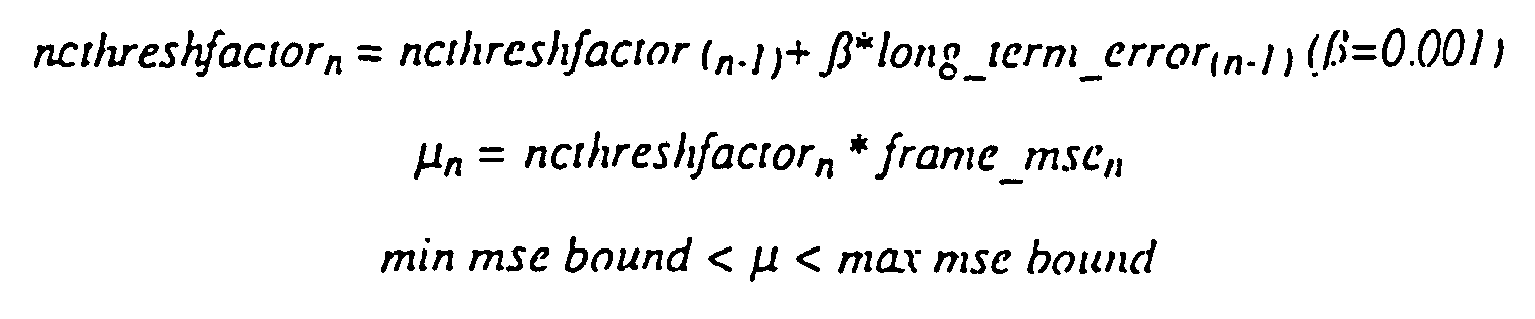
long_term_error, which will be discussed in more detail below in the discussion of the improvedrate control mechanism 345, provides a benchmark for achieving the required datarate over a period of time. No-change blocks will be flagged more frequently if the long_term_error indicates that the datarate is too high. Conversely, no-change blocks will be flagged less frequently if the long_term_error indicates that the datarate produced is even lower than desired. Instead of reacting instantaneously, µ is buffered by β, which effectively controls the time constant (or "delay") of the reaction time to changing the datarate. This prevents oscillatory datarates and also allows a tolerance for more complex images with a lot of variation to generate more bits, and less complex images with less variation to generate less bits, instead of being driven entirely by a datarate. Because of the range of quality achievable in a given sequence, the no-change threshold µ maintains the quality of the most recently encoded pan of the sequence by taking into account frame_mse. Frame_mse is also used byrate control 345 and will be discussed in more detail in the rate control section. - Another technique performed by
preprocessor 320 in the preferred embodiment is that of spatial subsampling. Spatial subsampling is used to reduce the amount of information that is coded byvector quantizer 330. This results in faster encoding and more compression at the cost of some spatial quality. The primary challenge is to maintain high quality and compression. There are two approaches which can be taken by the preferred embodiment, each with different benefits. In the first approach, the image is separated into "smooth" and "detailed" regions by some measure, where blocks that are "smooth" are subsampled according to datarate demands. For example, "smooth" regions may be determined by comparing the mean squared error between the original block and the corresponding subsampled and upsampled block. This is advantageous because "smooth" regions that are subsampled usually produce the least noticeable artifacts or error. An additional benefit to this approach occurs when two separate codebooks are generated for subsampled and 2x2C ("change") blocks, and each codebook is shared across several frames. With subsampling based entirely on "smoothness", the two codebooks are able to represent the "smooth" and "detailed" areas well across many frames, because the image vectors in the "smooth" areas are usually very similar across many frames, and the same is true for "detailed" regions. In the second approach, where zones are used, the location of the block in the image also affects the subsampling decision. The advantages of the second approach include the ability to efficiently (in terms of bits) communicate to the decoder which areas of the image to postfilter, and more efficient run length blockheader coding by congregating subsample blocks together. - The subsampling process is discussed with reference to
Figure 5a . For subsampling, the image is divided into 4x4 blocks such as shown inFigure 5a . Each 4x4 block is reduced to a 2x2 block such as 510 if it is selected to be subsampled. A filtering subsampling operation performed in the preferred embodiment actually uses a weighted average of each of the four 4x4 pixel blocks (e.g. block 518, comprising pixels 1-3, 5-7, 9-11, and 17-23) for representing the subsampled block 516 (block ofpixels subsampled block 510, in a simpler subsampling scheme. If the entire image were subsampled using either of these techniques, the number of vectors going into improvedvector quantizer 330 would be reduced by a factor of 4, and therefore, the number of codebook indices in the final bitstream would also be reduced by a factor of 4. In alternative embodiments, subsampling can also be done only in the horizontal direction, or only in vertical direction, or by more than just a factor of 2 in each direction by sampling blocks larger than 4x4 pixels into 2x2 pixel blocks. During decoding,improved decoder 351 detects, in a header preceding the indices, that the indices contained in a block such as 510 refer to subsampled blocks, and replicates each pixel by one in both the horizontal and the vertical directions in order to recreate a full 4x4 block such as 520 (e.g. see, block 521 comprising 4 pixels, which each are equal topixel 1 in the simple subsampling case). Note thatblock 521 can also be represented by four γ's instead of four 1's, where γ is a weighted average ofblock 518. In another alternative embodiment, the pixels between existing pixels can be interpolated from neighboring pixels in order to obtain better results. This, however, can have a detrimental effect on the speed of the decoder. - The method by which "smoothness" is determined is based on how much squared error would result if a block were to be subsampled. The subsampling operation may include filtering as well, as illustrated in the following error calculation. The squared error ε is calculated between each pixel of a 2x2 block such as 560 shown in
Figure 5b (comprising pixels a0-a3) and the average γ of its surrounding 4x4 block 555 (comprising pixels a0-a3 and b0-b11):
γ calculated fromblock 518 is used in place of the value ofpixel 1 in2x2 block 521. If a 2x2 block such as 560 were to be subsampled, then the average of its surrounding 4x4 γ (block 555), would be transmitted instead of the four individual pixel values a0-a3. The average γ is useful in reducing blockiness. Thus, as shown with reference toFigure 5 , the value γ is transmitted instead of the four original pixel values a0-a3 of block 530. The squared error ε is then scaled by a weighting coefficient k to approximate the human visual system's luminance sensitivity (or the SNR can be used as a rough approximation instead of MSE). Thus regions of high luminance are more easily subsampled assuming the subsampling errors are the same. The four scaled errors are then added to generate the error associated with each 2x2 block such as 560:
- In order to rank a
4x4 block 500 as a candidate for subsampling, each of the subsampling errors ε from the four 2x2 blocks of pixels aligned at the corners within the4x4 500 are added. Blocks are chosen for subsampling from smallest error to largest error blocks until the rate control determines that enough blocks have been subsampled to meet the desired frame size. In an alternative embodiment, edges in the image may be extracted by edge detection methods known to those skilled in the art in order to prevent edges from being subsampled. Basing the decision to subsample on subsampling error has a tendency to preserve most edges, because subsampling and then upsampling across edges tend to produce the largest errors. But, it is also useful in some circumstances to explicitly protect edges that are found by edge detection. - Subsampling purely on the basis of error works in most cases, but there are images where subsampled blocks do not necessarily occur adjacent to each other. Consequently, the appearance of subsampled blocks next to non-subsampled blocks can cause a scintillating effect that can be visually distracting to a viewer. It appears as if blocks are moving because some blocks are subsampled and others aren't. Secondly, if subsampled blocks and standard encoded blocks are mixed together spatially, considerable bandwidth (in bits) is consumed by having to delineate block type changes by block headers which are identified by preprocessor 320 (block headers are discussed in more detail below with reference to the bitstream syntax). In such images, zones can be used in the encoding scheme of an alternative embodiment to reduce the two aforementioned shortcomings of subsampling based on error alone. The image is divided by
preprocessor 320 into 32 rectangular zones (eight horizontal and four vertical), each of which has a weighting associated with them. Obviously, the number of zones and their sizes can be fairly diverse. In one embodiment, weighting the border zones of the image may be performed so that it is more difficult to subsample the center zones. This assumes that the viewer will pay less attention to the edges of the image because the camera will be roughly centered on the object of interest. Another embodiment uses fast motion to conceal some of the subsampling artifacts. If the motion is not 'fast', as determined by motion estimation algorithms known to those skilled in the an. it may be useful to make it more difficult to subsample areas of motion. This assumes that the viewer will track objects of motion, and will notice subsampling artifacts unless the motion is fast. - In the second approach of the preferred embodiment, zones are soned according to their zonal errors, which is the average squared error ε̂:


and each zone is weighted according to its location to produce zone error ZE:
- Blocks tagged for subsampling are subsampled in order of best to worst zones, in terms of zone error, until the number of subsampled blocks requested by
rate control 345 is reached.Improved decoder 351 is able to determine from theinput bitstream 350 which zones have been subsampled and, depending on certain criteria (such as quality settings, etc.), may decide whether or not to postfilter (process 375) those zones during decoding in order to soften blockiness. Because subsampling is zonal,decoder 351 knows where to concentrate its efforts instead of trying to postfilter the entire image. The overhead required to communicate this information to the decoder is minimal, only 32-bits for the 32 rectangular zone case. - In order to prevent the entire zone from being subsampled, only blocks which have errors less than the edge_mse are subsampled within the zone. The edge_mse value is controlled by the rate control, so more blocks are preserved from subsampling if the compressed frame size desired is large.

- In an alternative embodiment, the edge_mse can be weighted so that edges in the image, extracted by edge detection methods known to those skilled in the art. are preserved from subsampling.
- Spatial redundancy may also be reduced with minimal smearing of edges and detail by performing "directional" filtering in an alternative embodiment. This processing performs a horizontal, vertical, upward diagonal and downward diagonal filter over an area surrounding a pixel and chooses the filter producing the minimum error. If the filter length is 3 taps (filter coefficients), computing the
filtered value ofpixel 6 inFigure 5a would mean applying the filter topixels pixels pixels pixels pixel 6. For example, in order to perform the "horizontal filter," the value may be represented as fh wherein fh is computed in the following manner:
wherein a1, a2, and a3 are weighting coefficients. a1 , a2 , and a3 may be equal to 0.25, 0.5, and .25, respectively, so that more weight is given tocenter pixel 6 of the 3x3 block and the result fh may be computed using computationally inexpensive shift operations. Note that these filters can be applied in three dimensional space as well, where the additional dimension is time in yet another alternative embodiment. - Comparing the results of these directional filters also gives information about the orientation of the edges in the image. The orientation of the edge may be extracted by comparing the ratio of the errors associated with orthogonal direction pairs. The first step is to select the direction which produced the minimum error, min_directional_error, and compare this error with the errors associated with the filter in the other three directions. Characteristics which would indicate that there is a directional edge in the direction of the minimum error filter include:
- the direction orthogonal to that of the minimum error filter produced the maximum error
- the maximum error filter has an error significantly larger than the other three directions, particularly when compared to the direction orthogonal to itself
- The preferred embodiment also uses luminance and chrominance values (YUV) of the vectors for codebook generation and
vector quantizer 330 to improve speed and/or quality. The YUV values can be calculated from the red, green, and blue (RGB) values of the pixels in the vectors via a simpler transformation whose reconstruction is computationally inexpensive, such as the following transformation which is realizable by bit shifts instead of multiplication:


Performing codebook generation using YUV invector quantizer 330 can improve clustering because of the tighter dynamic range and the relative decorrelation among components. Consequently, improvement in quality is noticeable. For situations where encoding speed is important, the chrominance (U.V) values can be subsampled by 2 or 4 and weighted (by shifting, for example) in thevector quantization step 330. - In the preferred embodiment, luminance and chrominance is passed to
vector quantizer 330 bypreprocessor 320 after the preprocessing of RGB values such as subsampling or filtering of vectors of the input image. In an alternative embodiment, YUV transformation may be done first and preprocessing such as subsampling can be done after the YUV transformation. At any rate, the resulting preprocessed data passed toimproved VQ 330 is in YUV format. - Vector Quantization (VQ) is an efficient way for representing blocks or vectors of data. A sequence of data, pixels, audio samples or sensor data is often quantized by treating each datum independently. This is referred to as scalar quantization. VQ, on the other hand, quantizes blocks or vectors of data. A primary issue with VQ is the need to find a set of representative vectors, termed a codebook, which is an acceptable approximation of the data set. Acceptability is usually measured using the mean squared error between the original and reconstructed data set. A common technique for codebook generation is described in Linde, Y., Buzo, A., and Gray, R., "An Algorithm for Vector Quantizer Design," COM-28 IEEE Transactions on Communications 1 (January 1980) (known as the "LBG" algorithm). A technique which employs the LBG algorithm to generate a codebook starts by sampling input vectors from an image in order to generate an initial estimate of the codebook. Then, each of the input vectors is compared with the codebook entries and associated with the closest matching codebook entry. Codebook entries are iteratively updated by calculating the mean vector associated with each codebook entry and replacing the existing entry with the mean vector. Then, a determination is made whether the codebook then has improved significantly from a last iteration, and if not, the process repeats by comparing input vectors with codebook entries and re-associating, etc. This codebook generation may be done on a large sequence of images, the training set, or the codebook may be regenerated on each frame. In addition, this technique may be applied to binary trees used in certain prior art vector quantization systems for encoding efficiency.
- The
improved vector quantizer 330 is organized in a tree structure. Instead of a binary tree as used in certain prior art schemes, at the root of the tree, N child nodes 610, as shown inFigure 6 , are generated initially. This may be performed using a variety of techniques. For example, in one embodiment, a segmenter may be used to extract representative centroids from the image to generate the N initial nodes which contain the centroid values. In another embodiment, the initial centroids may be determined from an image by extracting N vectors from the image itself. Prior art binary trees have relied simply upon the establishment of two initial nodes. Binary trees suffer from the disadvantage that the errors in the two initial nodes propagate down to the rest of the nodes in the tree. In the preferred embodiment, N nodes are used wherein the value N varies depending on image characteristics. This advantage is related to the fact that more initial nodes reduce the chances of incorrect binning at the root level. Better quality and faster convergence can be achieved from using N initial nodes in creating the tree, where N adapts to the image and is usually greater than two. - The improved
vector quantization process 700 performed on the image is shown and discussed with reference toFigures 6 ,7 , and8 . The creation of the N initial nodes is performed atstep 702 shown inFigure 7 . The top layer of the tree 610 is improved from the N initial nodes by iteratively adjusting the values of the initial nodes and associating vectors with them atstep 703. This iterative process is described below with reference toFigure 8 , which shows an iterative node binning/recalculation process. Then, atstep 704, the node with the worst distortion is determined, where its distortion is calculated from a comparison between the node's centroid value and its associated vectors. In the preferred embodiment, mean squared error between the vectors associated with the node and the node's centroid value is used as a distortion measure. Note that the determination of which node is the most distorted may be made using many measures in alternative embodiments, including population, total distortion associated with the node, average distortion associated with the node and/or peak distortion associated with the node. At any rate, once the most distorted node is determined atstep 704, then this node is split into two children nodes atstep 705. Of course, even though two children nodes are described and used in the preferred embodiment, more than two children nodes may be created in an alternative embodiment. Then, an iterative process upon the children nodes is performed atstep 706 in order to obtain the best representative vectors. This process is described in more detail with reference toFigure 8 . - The iterative process such as used at
steps Figure 8 . This process starts atstep 801. Atstep 802, it then assigns representative centroids to the child nodes, such as 670 shown inFigure 6 , from the group of vectors associated with its parent node. In the case of a root node, all of the vectors of the image are used to create representative centroids. Then, each of the vectors is associated (or "binned") with the node having the closest centroid. Then, atstep 804, the error between the vectors associated with each of the centroids and the centroid itself is determined. The error calculation may be performed using a variety of techniques, however, in the preferred embodiment, a mean squared calculation is used. Once the error calculation has been determined atstep 805, it is determined whether the change in the error has become less than a certain threshold value. Instep 806, new centroids are calculated from the vectors associated with the nodes fromstep 803, and this done for all of the nodes fromstep 803. On a first iteration of the process shown in 706, the change in error will be very large, going from a large preset positive value to the error values calculated. However, on subsequent iterations of theloop comprising steps 803 through 806, the change in error will become smaller, eventually becoming less than the threshold values. If the change in total error associated with the node currently being split is not less than the threshold value as determined atstep 805, then the new centroids are recalculated atstep 806, and process 703 (706) continues to repeatsteps 803 through 806 again, as necessary. This is done until the change in error is less than the predetermined threshold value as detected atstep 805. Once the change in error becomes less than the threshold value as detected atstep 805, then process 703 (706) ends atstep 807 and returns to process 700 ofFigure 7 . - Once this iterative process is complete, at
step 707 inFigure 7 . it is determined whether the desired number of terminal nodes in the tree have been created. Each time a node is split, two or more additional child nodes are produced inVQ tree 600. Thus, in the preferred embodiment, the total number of terminal nodes desired determines how many times nodes inVQ tree 600 will be split.Process 700 continues atstep 704 through 707 until the desired number of terminal nodes in the tree have been created. Once the desired number of terminal nodes in the tree have been created, then process 700 is complete atstep 708, and the codebook may be transmitted on the output bitstream to packer/coder 340 shown inFigure 3 . - The type construct used in the preferred embodiment for a node is defined in the "C" programming language as follows:
  typedef struct mode (
         unsigned long *centroid:          // pointer to centroid for this node
         unsigned long *vect_index_list:   // pointer to list of vector indices associated with
                                      this node
         unsigned long num_vect:      // number of vectors associated with this node
         unsigned long distonion:     // total distortion associated with this node
         unsigned long avg_dist:      // Average distortion associated with this node
         unsigned long peak_dist:     // Peak distortion associated with this node
         unsigned long percent_dist:  // percentage distortion associated with this node
         unsigned long num_children:  // number of children
         unsigned long ic_method:     // method for initializing this node
         struct mode **children:      // pointer to a list of structures for the child
                                                 nodes of this node
         struct mode *parent:                    // pointer to the parent of this node
         unsigned char terminal:      // flag to indicate if this is a terminal node
         unsigned long *childrencptrs:// pointer to an array of pointers to
                                                          // centroids of children (used to
                                                          // simplify and speed up distortion
                                                          // calculation)
         )
Thus, the nodes comprising a tree VQ such as 600 each have a datum such as that defined above which may maintain certain information associated with them such as various distortion measures, number of binned vectors, number of children. etc. This information is useful for the tree creation process discussed above.
- 1. If the complete tree is to be updated, then a looser convergence criterion is applied to the initial N nodes. The complete tree may need to be updated in a case where a scene change has occurred or the image has changed significantly from the previous image.
- 2. If the root node from a previous tree is used in constructing the current tree then no iterations are performed on the root node. Root nodes may be reused where a like sequence of images is encoded and no scene change has yet been detected. Thus. N initial nodes such as 610 can be reused from a previous frame's VQ.
- 1. Total distortion associated with a specific node,
- 2. Average distortion associated with a specific node.
- 3. Population associated with a specific node.
- 4. Percentage distortion associated with a specific node.
- 5. Maximum distortion associated with a specific node.
- 6. Ratio of maximum to minimum distortion associated with a specific node.
- 1. Generate K candidate initial nodes by subsampling the vector list associated with the node.
- 2. Cluster the vector list using these initial nodes.
- 3. If the clustering fails (i.e. all the vectors cluster to one node), identify this node as having failed to cluster with this method.
- 4. When the next attempt is made to split this node, use a different initial estimate for the node centroids. Techniques for generating this estimate include but are not limited to:
- a. Perturb the centroid in the parent node; or
- b. Pick the most distorted vectors in the nodes vector list as the initial centroids.
- 5. Further attempts are made to cluster using these initial nodes. If all the methods fail to produce a split in the vector list the node is tagged as a terminal node and no further attempts are made to split it.


Claims (8)
- An apparatus for encoding an image represented by a plurality of blocks of pixels (516, 518) having smooth and detailed portions, said apparatus comprising:a preprocessor (320) configured to select a smooth portion of the plurality of blocks to subsample by calculating values indicative of distortion caused by subsampling the plurality of blocks;the preprocessor (320) being further configured to subsample the selected smooth portion of the plurality of blocks into subsampled blocks (510) to reduce the amount of data that must be encoded to encode the image; andan encoder (330) configured to receive the subsampled blocks(510) from said preprocessor (320) and non-subsampled blocks, said encoder (330) being further configured to encode the subsampled blocks and the non-subsampled blocks with separate codebooks.
- The apparatus of claim 1 wherein each of the values indicative of distortion is associated with a respective one of the plurality of blocks, and said preprocessor (320) is configured to subsample blocks of the plurality of blocks having values indicative of small distortion relative to others of the plurality of blocks.
- The apparatus of claim 1 wherein said encoder (330) is further configured to indicate that the subsampled blocks have been encoded with a first codebook and that the non-subsampled blocks have been encoded with a second codebook.
- A method of transmitting an image, the method comprising the steps of:separating the image into smooth regions and detailed regions based upon a comparision between pixels and neighboring pixels in the image;encoding the smooth regions of the image with a first codebook;subsampling the smooth regions prior to said step of encoding the smooth regions with the first codebook;wherein said step of separating the image into smooth regions and detailed regions comprises the step of calculating, for each one of a plurality of blocks of pixels comprised by the image, an error value indicative of distortion that would result if the one of the plurality of pixel blocks was subsampled, the smooth regions being defined by pixel blocks having lower error values than pixel blocks defining the detailed regions.
- An apparatus for decoding an encoded image, said apparatus comprising:a receiving unit configured to receive a datastream including a first codebook index, a second codebook index and information indicating for each of the first codebook index and the second codebook index whether a subsampled block-type (510) from a smooth region of the encoded image or a non-subsampled block-typefrom a detailed region of the encoded image is represented;an unpacker (370) coupled to said receiving unit and receiving the datastream therefrom, said unpacker being configured to detect the information indicating whether a subsampled block-type or non-subsampled block-type is represented and to decode each one of the first codebook index and the second codebook index using either a first codebook or a second codebook according to whether the one of the first codebook index and the second codebook index represents a subsampled block-type or a non-subsampled block-type.
- The apparatus of claim 5 wherein said receiving unit comprises a codebook regenerator (360) and the datastream further includes codebook vectors, said codebook regenerator being configured to generate the first and second codebooks from the codebook vectors.
- A method of decoding an encoded image, said method comprising the steps of:receiving a datastream, the datastream including a first codebook index, a second codebook index and information indicating for each of the first codebook index and the second codebook index whether a subsampled block-type from a smooth region of the encoded image or a non-subsampled block-typefrom a detailed region of the encoded image is represented;detecting the information indicating whether a subsampled block-type or non-subsampled block-type is represented;decoding each one of the first codebook index and the second codebook index using either a first codebook or a second codebook according to whether the one of the first codebook index and the second codebook index represents a subsampled block-type or a non-subsampled block-type.
- The method of claim 7 wherein the datastream further includes codebook vectors, and further comprising the step of generating the first and second codebooks from the codebook vectors after the codebook vectors have been received.
Applications Claiming Priority (3)
| Application Number | Priority Date | Filing Date | Title |
|---|---|---|---|
| US93895992A | 1992-09-01 | 1992-09-01 | |
| US938959 | 1992-09-01 | ||
| EP93920451A EP0658263B1 (en) | 1992-09-01 | 1993-08-31 | Improved vector quantization |
Related Parent Applications (2)
| Application Number | Title | Priority Date | Filing Date |
|---|---|---|---|
| EP93920451A Division EP0658263B1 (en) | 1992-09-01 | 1993-08-31 | Improved vector quantization |
| EP93920451.7 Division | 1994-03-17 |
Publications (3)
| Publication Number | Publication Date |
|---|---|
| EP1139289A2 EP1139289A2 (en) | 2001-10-04 |
| EP1139289A3 EP1139289A3 (en) | 2006-06-28 |
| EP1139289B1 true EP1139289B1 (en) | 2011-03-09 |
Family
ID=25472287
Family Applications (3)
| Application Number | Title | Priority Date | Filing Date |
|---|---|---|---|
| EP01110017A Expired - Lifetime EP1139289B1 (en) | 1992-09-01 | 1993-08-31 | Improved vector quantization |
| EP93920451A Expired - Lifetime EP0658263B1 (en) | 1992-09-01 | 1993-08-31 | Improved vector quantization |
| EP03076435A Withdrawn EP1341126A3 (en) | 1992-09-01 | 1993-08-31 | Image compression using a shared codebook |
Family Applications After (2)
| Application Number | Title | Priority Date | Filing Date |
|---|---|---|---|
| EP93920451A Expired - Lifetime EP0658263B1 (en) | 1992-09-01 | 1993-08-31 | Improved vector quantization |
| EP03076435A Withdrawn EP1341126A3 (en) | 1992-09-01 | 1993-08-31 | Image compression using a shared codebook |
Country Status (7)
| Country | Link |
|---|---|
| US (2) | US5649030A (en) |
| EP (3) | EP1139289B1 (en) |
| JP (1) | JPH08502865A (en) |
| AU (1) | AU5099593A (en) |
| CA (1) | CA2143633A1 (en) |
| DE (2) | DE69333288T2 (en) |
| WO (1) | WO1994006099A1 (en) |
Families Citing this family (155)
| Publication number | Priority date | Publication date | Assignee | Title |
|---|---|---|---|---|
| EP0735775B1 (en) * | 1995-03-31 | 2003-05-14 | Canon Kabushiki Kaisha | Image processing apparatus and method |
| US5832131A (en) * | 1995-05-03 | 1998-11-03 | National Semiconductor Corporation | Hashing-based vector quantization |
| AU727706B2 (en) * | 1995-10-20 | 2000-12-21 | Facebook, Inc. | Repetitive sound compression system |
| US6678311B2 (en) | 1996-05-28 | 2004-01-13 | Qualcomm Incorporated | High data CDMA wireless communication system using variable sized channel codes |
| US6144771A (en) * | 1996-06-28 | 2000-11-07 | Competitive Technologies Of Pa, Inc. | Method and apparatus for encoding and decoding images |
| US5926226A (en) * | 1996-08-09 | 1999-07-20 | U.S. Robotics Access Corp. | Method for adjusting the quality of a video coder |
| US5946454A (en) * | 1996-08-15 | 1999-08-31 | Seiko Epson Corporation | Image enhancement during half-toning using low-pass and high-pass filtering |
| DE59709799D1 (en) * | 1996-10-01 | 2003-05-15 | Infineon Technologies Ag | METHOD AND ARRANGEMENT FOR VECTOR QUANTIZATION AND FOR INVERSE VECTOR QUANTIZATION OF A DIGITALIZED IMAGE |
| US5931904A (en) * | 1996-10-11 | 1999-08-03 | At&T Corp. | Method for reducing the delay between the time a data page is requested and the time the data page is displayed |
| EP1471464A3 (en) * | 1996-10-31 | 2009-07-15 | Sensormatic Electronics Corporation | Intelligent video information management system |
| FR2757296B1 (en) * | 1996-12-13 | 2001-10-12 | Sgs Thomson Microelectronics | METHOD AND DEVICE FOR ESTIMATING MOTION OF PORTIONS OF IMAGES FOR MOBILE IMAGE COMPRESSION CIRCUIT |
| US5974175A (en) * | 1997-01-22 | 1999-10-26 | Fujitsu Limited | Image processing apparatus and method for detecting a contour of an object from images of a motion picture and extracting the object therefrom |
| JPH10285603A (en) * | 1997-02-10 | 1998-10-23 | Kokusai Electric Co Ltd | Image coding method |
| US6786420B1 (en) | 1997-07-15 | 2004-09-07 | Silverbrook Research Pty. Ltd. | Data distribution mechanism in the form of ink dots on cards |
| US6728775B1 (en) | 1997-03-17 | 2004-04-27 | Microsoft Corporation | Multiple multicasting of multimedia streams |
| KR100232098B1 (en) | 1997-03-26 | 1999-12-01 | 서평원 | Device for controlling rate of MPEG video signal using fuzzy control |
| US6459433B1 (en) * | 1997-04-30 | 2002-10-01 | Ati Technologies, Inc. | Method and apparatus for compression of a two dimensional video object |
| US6266419B1 (en) * | 1997-07-03 | 2001-07-24 | At&T Corp. | Custom character-coding compression for encoding and watermarking media content |
| US6618117B2 (en) | 1997-07-12 | 2003-09-09 | Silverbrook Research Pty Ltd | Image sensing apparatus including a microcontroller |
| US6624848B1 (en) | 1997-07-15 | 2003-09-23 | Silverbrook Research Pty Ltd | Cascading image modification using multiple digital cameras incorporating image processing |
| US6690419B1 (en) | 1997-07-15 | 2004-02-10 | Silverbrook Research Pty Ltd | Utilising eye detection methods for image processing in a digital image camera |
| US7110024B1 (en) | 1997-07-15 | 2006-09-19 | Silverbrook Research Pty Ltd | Digital camera system having motion deblurring means |
| US20040119829A1 (en) | 1997-07-15 | 2004-06-24 | Silverbrook Research Pty Ltd | Printhead assembly for a print on demand digital camera system |
| US6879341B1 (en) | 1997-07-15 | 2005-04-12 | Silverbrook Research Pty Ltd | Digital camera system containing a VLIW vector processor |
| US6161086A (en) * | 1997-07-29 | 2000-12-12 | Texas Instruments Incorporated | Low-complexity speech coding with backward and inverse filtered target matching and a tree structured mutitap adaptive codebook search |
| US5930393A (en) * | 1997-08-11 | 1999-07-27 | Lucent Technologies Inc. | Method and apparatus for enhancing degraded document images |
| US6775417B2 (en) * | 1997-10-02 | 2004-08-10 | S3 Graphics Co., Ltd. | Fixed-rate block-based image compression with inferred pixel values |
| US5956431A (en) * | 1997-10-02 | 1999-09-21 | S3 Incorporated | System and method for fixed-rate block-based image compression with inferred pixel values |
| US6658146B1 (en) | 1997-10-02 | 2003-12-02 | S3 Graphics Co., Ltd. | Fixed-rate block-based image compression with inferred pixel values |
| US6683978B1 (en) | 1997-10-02 | 2004-01-27 | S3 Graphics Co., Ltd. | Fixed-rate block-based image compression with inferred pixel values |
| JP3556447B2 (en) * | 1997-11-07 | 2004-08-18 | シャープ株式会社 | Color solid-state imaging camera system |
| DE69735262D1 (en) | 1997-11-24 | 2006-04-20 | St Microelectronics Srl | MPEG-2 decoding with reduced memory requirements through recompression with adaptive tree-structured vector quantization |
| JP3421700B2 (en) * | 1998-01-22 | 2003-06-30 | 富士通株式会社 | Data compression device and decompression device and method thereof |
| US6345126B1 (en) * | 1998-01-29 | 2002-02-05 | Xerox Corporation | Method for transmitting data using an embedded bit stream produced in a hierarchical table-lookup vector quantizer |
| US6396956B1 (en) * | 1998-03-31 | 2002-05-28 | Sharp Laboratories Of America, Inc. | Method and apparatus for selecting image data to skip when encoding digital video |
| WO1999055093A1 (en) * | 1998-04-17 | 1999-10-28 | Ultraclean Technology Research Institute, Co., Ltd. | Data compressing device and method, data expanding device and method, data compressing/expanding system and method, code book making method, and vector quantizing device and method |
| US6377706B1 (en) * | 1998-05-12 | 2002-04-23 | Xerox Corporation | Compression framework incorporating decoding commands |
| GB2339300B (en) | 1998-07-06 | 2002-10-16 | Bookham Technology Ltd | A hermetically sealed optic fibre package and method of assembly |
| AUPP702098A0 (en) | 1998-11-09 | 1998-12-03 | Silverbrook Research Pty Ltd | Image creation method and apparatus (ART73) |
| US6195394B1 (en) * | 1998-11-30 | 2001-02-27 | North Shore Laboratories, Inc. | Processing apparatus for use in reducing visible artifacts in the display of statistically compressed and then decompressed digital motion pictures |
| AUPQ056099A0 (en) | 1999-05-25 | 1999-06-17 | Silverbrook Research Pty Ltd | A method and apparatus (pprint01) |
| US6594627B1 (en) * | 2000-03-23 | 2003-07-15 | Lucent Technologies Inc. | Methods and apparatus for lattice-structured multiple description vector quantization coding |
| AU5235501A (en) * | 2000-05-03 | 2001-11-12 | Clearstream Technologies Limited | Video data transmission |
| MXPA02012167A (en) | 2000-06-19 | 2004-08-19 | Correlogic Systems Inc | Heuristic method of classification. |
| SG144731A1 (en) * | 2000-07-18 | 2008-08-28 | Correlogic Systems Inc | A process for discriminating between biological states based on hidden patterns from biological data |
| US20020090140A1 (en) * | 2000-08-04 | 2002-07-11 | Graham Thirsk | Method and apparatus for providing clinically adaptive compression of imaging data |
| US7069545B2 (en) * | 2000-12-29 | 2006-06-27 | Intel Corporation | Quantization and compression for computation reuse |
| WO2002054780A1 (en) * | 2001-01-04 | 2002-07-11 | Northshore Laboratories, Inc. | Apparatus for artifacts reduction in the display of decompressed motion pictures |
| US7209519B2 (en) * | 2001-04-16 | 2007-04-24 | Mitsubishi Electric Research Laboratories, Inc. | Encoding a video with a variable frame-rate while minimizing total average distortion |
| US7035459B2 (en) * | 2001-05-14 | 2006-04-25 | Nikon Corporation | Image compression apparatus and image compression program |
| US6807312B2 (en) | 2001-07-13 | 2004-10-19 | Sharp Laboratories Of America, Inc. | Robust codebooks for vector quantization |
| US7457358B2 (en) * | 2001-09-26 | 2008-11-25 | Interact Devices, Inc. | Polymorphic codec system and method |
| US7302102B2 (en) * | 2001-09-26 | 2007-11-27 | Reynolds Jodie L | System and method for dynamically switching quality settings of a codec to maintain a target data rate |
| US7599434B2 (en) * | 2001-09-26 | 2009-10-06 | Reynolds Jodie L | System and method for compressing portions of a media signal using different codecs |
| EP1438673B1 (en) * | 2001-09-26 | 2012-11-21 | Interact Devices Inc. | System and method for communicating media signals |
| US7457359B2 (en) * | 2001-09-26 | 2008-11-25 | Mabey Danny L | Systems, devices and methods for securely distributing highly-compressed multimedia content |
| US7203635B2 (en) * | 2002-06-27 | 2007-04-10 | Microsoft Corporation | Layered models for context awareness |
| AU2003261273A1 (en) * | 2002-07-29 | 2004-02-16 | Correlogic Systems, Inc. | Quality assurance for high-throughput bioassay methods |
| US7903892B2 (en) * | 2002-10-29 | 2011-03-08 | Ati Technologies Ulc | Image analysis for image compression suitability and real-time selection |
| US7430497B2 (en) * | 2002-10-31 | 2008-09-30 | Microsoft Corporation | Statistical model for global localization |
| US7009594B2 (en) * | 2002-10-31 | 2006-03-07 | Microsoft Corporation | Universal computing device |
| US7133563B2 (en) * | 2002-10-31 | 2006-11-07 | Microsoft Corporation | Passive embedded interaction code |
| US7116840B2 (en) | 2002-10-31 | 2006-10-03 | Microsoft Corporation | Decoding and error correction in 2-D arrays |
| US7502507B2 (en) * | 2002-10-31 | 2009-03-10 | Microsoft Corporation | Active embedded interaction code |
| US20040140962A1 (en) * | 2003-01-21 | 2004-07-22 | Microsoft Corporation | Inertial sensors integration |
| US7643679B2 (en) * | 2003-02-13 | 2010-01-05 | Ati Technologies Ulc | Method and apparatus for block based image compression with multiple non-uniform block encodings |
| US7764833B2 (en) | 2003-02-13 | 2010-07-27 | Ati Technologies Ulc | Method and apparatus for anti-aliasing using floating point subpixel color values and compression of same |
| US8111928B2 (en) | 2003-02-13 | 2012-02-07 | Ati Technologies Ulc | Method and apparatus for compression of multi-sampled anti-aliasing color data |
| US7274831B2 (en) * | 2003-04-03 | 2007-09-25 | Microsoft Corporation | High quality anti-aliasing |
| GB2400291A (en) * | 2003-04-05 | 2004-10-06 | Autodesk Canada Inc | Image processing using switch nodes |
| US6798360B1 (en) * | 2003-06-27 | 2004-09-28 | Canadian Space Agency | Method and system for compressing a continuous data flow in real-time using recursive hierarchical self-organizing cluster vector quantization (HSOCVQ) |
| US7551785B2 (en) * | 2003-07-03 | 2009-06-23 | Canadian Space Agency | Method and system for compressing a continuous data flow in real-time using cluster successive approximation multi-stage vector quantization (SAMVQ) |
| MXPA06001170A (en) * | 2003-08-01 | 2006-05-15 | Correlogic Systems Inc | Multiple high-resolution serum proteomic features for ovarian cancer detection. |
| US7761239B2 (en) * | 2003-12-11 | 2010-07-20 | Correlogic Systems, Inc. | Method of diagnosing biological states through the use of a centralized, adaptive model, and remote sample processing |
| US7583842B2 (en) | 2004-01-06 | 2009-09-01 | Microsoft Corporation | Enhanced approach of m-array decoding and error correction |
| US7263224B2 (en) | 2004-01-16 | 2007-08-28 | Microsoft Corporation | Strokes localization by m-array decoding and fast image matching |
| US7502505B2 (en) * | 2004-03-15 | 2009-03-10 | Microsoft Corporation | High-quality gradient-corrected linear interpolation for demosaicing of color images |
| US7751483B1 (en) * | 2004-04-16 | 2010-07-06 | Majesco Entertainment Company | Video codec for embedded handheld devices |
| US20060158677A1 (en) * | 2005-01-18 | 2006-07-20 | Atousa Soroushi | Enhanced image data processing method and apparatus |
| EP1861704A2 (en) * | 2005-02-09 | 2007-12-05 | Correlogic Systems, Inc. | Identification of bacteria and spores |
| US7607076B2 (en) | 2005-02-18 | 2009-10-20 | Microsoft Corporation | Embedded interaction code document |
| US7826074B1 (en) | 2005-02-25 | 2010-11-02 | Microsoft Corporation | Fast embedded interaction code printing with custom postscript commands |
| JP4215014B2 (en) * | 2005-03-17 | 2009-01-28 | ソニー株式会社 | Image processing apparatus and image processing program |
| US7606429B2 (en) * | 2005-03-25 | 2009-10-20 | Ati Technologies Ulc | Block-based image compression method and apparatus |
| US7599560B2 (en) | 2005-04-22 | 2009-10-06 | Microsoft Corporation | Embedded interaction code recognition |
| US7421439B2 (en) | 2005-04-22 | 2008-09-02 | Microsoft Corporation | Global metadata embedding and decoding |
| US20080312514A1 (en) * | 2005-05-12 | 2008-12-18 | Mansfield Brian C | Serum Patterns Predictive of Breast Cancer |
| US7400777B2 (en) | 2005-05-25 | 2008-07-15 | Microsoft Corporation | Preprocessing for information pattern analysis |
| US7505624B2 (en) * | 2005-05-27 | 2009-03-17 | Ati Technologies Ulc | Block-based image compression method and apparatus |
| US7729539B2 (en) | 2005-05-31 | 2010-06-01 | Microsoft Corporation | Fast error-correcting of embedded interaction codes |
| US7580576B2 (en) | 2005-06-02 | 2009-08-25 | Microsoft Corporation | Stroke localization and binding to electronic document |
| US7619607B2 (en) | 2005-06-30 | 2009-11-17 | Microsoft Corporation | Embedding a pattern design onto a liquid crystal display |
| US7622182B2 (en) | 2005-08-17 | 2009-11-24 | Microsoft Corporation | Embedded interaction code enabled display |
| US7817816B2 (en) | 2005-08-17 | 2010-10-19 | Microsoft Corporation | Embedded interaction code enabled surface type identification |
| US8160160B2 (en) * | 2005-09-09 | 2012-04-17 | Broadcast International, Inc. | Bit-rate reduction for multimedia data streams |
| JP4844449B2 (en) * | 2006-04-17 | 2011-12-28 | 日本ビクター株式会社 | Moving picture encoding apparatus, method, program, moving picture decoding apparatus, method, and program |
| US20080201095A1 (en) * | 2007-02-12 | 2008-08-21 | Yip Ping F | Method for Calibrating an Analytical Instrument |
| US8411777B2 (en) * | 2007-06-22 | 2013-04-02 | Alcatel Lucent | Complex vector quantization codebook for use in downlink multi-user MIMO mobile broadcast systems |
| US8664358B2 (en) | 2007-06-29 | 2014-03-04 | Vermillion, Inc. | Predictive markers for ovarian cancer |
| EP2277317B1 (en) * | 2008-05-19 | 2021-01-27 | Citrix Systems, Inc. | Systems and methods for enhanced image encoding |
| US8774534B2 (en) | 2009-04-08 | 2014-07-08 | Watchitoo, Inc. | System and method for image compression |
| US9253505B2 (en) * | 2009-04-08 | 2016-02-02 | Newrow, Inc. | System and method for image compression |
| CN101577551A (en) * | 2009-05-27 | 2009-11-11 | 华为技术有限公司 | Method and device for generating lattice vector quantization codebook |
| US8860781B2 (en) * | 2009-06-30 | 2014-10-14 | Qualcomm Incorporated | Texture compression in a video decoder for efficient 2D-3D rendering |
| EP2467829A1 (en) * | 2009-08-20 | 2012-06-27 | Thomson Licensing | Method and apparatus for reusing tree structures to encode and decode binary sets |
| US8472712B2 (en) * | 2009-10-20 | 2013-06-25 | Apple Inc. | System and method for applying lens shading correction during image processing |
| US8259198B2 (en) * | 2009-10-20 | 2012-09-04 | Apple Inc. | System and method for detecting and correcting defective pixels in an image sensor |
| US8638342B2 (en) * | 2009-10-20 | 2014-01-28 | Apple Inc. | System and method for demosaicing image data using weighted gradients |
| US8593483B2 (en) * | 2009-10-20 | 2013-11-26 | Apple Inc. | Temporal filtering techniques for image signal processing |
| US8294781B2 (en) * | 2009-10-20 | 2012-10-23 | Apple Inc. | System and method for sharpening image data |
| WO2011090790A1 (en) | 2010-01-22 | 2011-07-28 | Thomson Licensing | Methods and apparatus for sampling -based super resolution vido encoding and decoding |
| US9813707B2 (en) | 2010-01-22 | 2017-11-07 | Thomson Licensing Dtv | Data pruning for video compression using example-based super-resolution |
| US8525895B2 (en) | 2010-07-29 | 2013-09-03 | Apple Inc. | Binning compensation filtering techniques for image signal processing |
| US8493482B2 (en) | 2010-08-18 | 2013-07-23 | Apple Inc. | Dual image sensor image processing system and method |
| CN102405622B (en) * | 2010-08-24 | 2014-11-05 | 华为技术有限公司 | Methods and devices for binary tree construction, compression and lookup |
| US8922704B2 (en) | 2010-09-01 | 2014-12-30 | Apple Inc. | Techniques for collection of auto-focus statistics |
| US9398205B2 (en) | 2010-09-01 | 2016-07-19 | Apple Inc. | Auto-focus control using image statistics data with coarse and fine auto-focus scores |
| US8605167B2 (en) | 2010-09-01 | 2013-12-10 | Apple Inc. | Flexible color space selection for auto-white balance processing |
| US8531542B2 (en) | 2010-09-01 | 2013-09-10 | Apple Inc. | Techniques for acquiring and processing statistics data in an image signal processor |
| WO2012033970A1 (en) | 2010-09-10 | 2012-03-15 | Thomson Licensing | Encoding of a picture in a video sequence by example - based data pruning using intra- frame patch similarity |
| WO2012033972A1 (en) | 2010-09-10 | 2012-03-15 | Thomson Licensing | Methods and apparatus for pruning decision optimization in example-based data pruning compression |
| US20130163679A1 (en) * | 2010-09-10 | 2013-06-27 | Dong-Qing Zhang | Video decoding using example-based data pruning |
| WO2012050832A1 (en) * | 2010-09-28 | 2012-04-19 | Google Inc. | Systems and methods utilizing efficient video compression techniques for providing static image data |
| US8786625B2 (en) | 2010-09-30 | 2014-07-22 | Apple Inc. | System and method for processing image data using an image signal processor having back-end processing logic |
| US8508612B2 (en) | 2010-09-30 | 2013-08-13 | Apple Inc. | Image signal processor line buffer configuration for processing ram image data |
| US8629913B2 (en) | 2010-09-30 | 2014-01-14 | Apple Inc. | Overflow control techniques for image signal processing |
| US8471932B2 (en) | 2010-09-30 | 2013-06-25 | Apple Inc. | Spatial filtering for image signal processing |
| US8508621B2 (en) | 2010-09-30 | 2013-08-13 | Apple Inc. | Image sensor data formats and memory addressing techniques for image signal processing |
| US8488055B2 (en) | 2010-09-30 | 2013-07-16 | Apple Inc. | Flash synchronization using image sensor interface timing signal |
| US8736700B2 (en) | 2010-09-30 | 2014-05-27 | Apple Inc. | Techniques for synchronizing audio and video data in an image signal processing system |
| CN101990104A (en) * | 2010-11-17 | 2011-03-23 | 中兴通讯股份有限公司 | Method and device for coding video images |
| US8855911B2 (en) | 2010-12-09 | 2014-10-07 | Honeywell International Inc. | Systems and methods for navigation using cross correlation on evidence grids |
| US8818722B2 (en) | 2011-11-22 | 2014-08-26 | Honeywell International Inc. | Rapid lidar image correlation for ground navigation |
| WO2013118216A1 (en) * | 2012-02-07 | 2013-08-15 | パナソニック株式会社 | Image processing device and image processing method |
| US11089247B2 (en) | 2012-05-31 | 2021-08-10 | Apple Inc. | Systems and method for reducing fixed pattern noise in image data |
| US8953882B2 (en) | 2012-05-31 | 2015-02-10 | Apple Inc. | Systems and methods for determining noise statistics of image data |
| US8872946B2 (en) | 2012-05-31 | 2014-10-28 | Apple Inc. | Systems and methods for raw image processing |
| US8817120B2 (en) | 2012-05-31 | 2014-08-26 | Apple Inc. | Systems and methods for collecting fixed pattern noise statistics of image data |
| US9332239B2 (en) | 2012-05-31 | 2016-05-03 | Apple Inc. | Systems and methods for RGB image processing |
| US9743057B2 (en) | 2012-05-31 | 2017-08-22 | Apple Inc. | Systems and methods for lens shading correction |
| US9105078B2 (en) | 2012-05-31 | 2015-08-11 | Apple Inc. | Systems and methods for local tone mapping |
| US9142012B2 (en) | 2012-05-31 | 2015-09-22 | Apple Inc. | Systems and methods for chroma noise reduction |
| US9031319B2 (en) | 2012-05-31 | 2015-05-12 | Apple Inc. | Systems and methods for luma sharpening |
| US9077943B2 (en) | 2012-05-31 | 2015-07-07 | Apple Inc. | Local image statistics collection |
| US9014504B2 (en) | 2012-05-31 | 2015-04-21 | Apple Inc. | Systems and methods for highlight recovery in an image signal processor |
| US8917336B2 (en) | 2012-05-31 | 2014-12-23 | Apple Inc. | Image signal processing involving geometric distortion correction |
| US9025867B2 (en) | 2012-05-31 | 2015-05-05 | Apple Inc. | Systems and methods for YCC image processing |
| US9157743B2 (en) | 2012-07-18 | 2015-10-13 | Honeywell International Inc. | Systems and methods for correlating reduced evidence grids |
| KR101348959B1 (en) * | 2013-06-04 | 2014-01-14 | 한국항공우주연구원 | Method for four path tree structured vector quantization |
| JP6542796B2 (en) | 2014-03-28 | 2019-07-10 | サムスン エレクトロニクス カンパニー リミテッド | Linear prediction coefficient quantization method and device thereof, and linear prediction coefficient inverse quantization method and device |
| EP3142110B1 (en) | 2014-05-07 | 2024-06-26 | Samsung Electronics Co., Ltd. | Device for quantizing linear predictive coefficient |
| KR20160030701A (en) * | 2014-09-11 | 2016-03-21 | 삼성전자주식회사 | Host divice transmitting print data to printer and method for rendering print data by host device |
| US9456075B2 (en) * | 2014-10-13 | 2016-09-27 | Avaya Inc. | Codec sequence detection |
| US10349064B2 (en) * | 2015-03-10 | 2019-07-09 | Apple Inc. | Adaptive chroma downsampling and color space conversion techniques |
| US20220156982A1 (en) * | 2020-11-19 | 2022-05-19 | Nvidia Corporation | Calculating data compression parameters |
Family Cites Families (18)
| Publication number | Priority date | Publication date | Assignee | Title |
|---|---|---|---|---|
| JPS60158788A (en) * | 1984-01-30 | 1985-08-20 | Mitsubishi Electric Corp | Vector quantizer of action compensation |
| JPS61118085A (en) * | 1984-11-14 | 1986-06-05 | Nec Corp | Coding system and device for picture signal |
| JPS62181576A (en) * | 1986-02-05 | 1987-08-08 | Fuji Photo Film Co Ltd | Radiograph information compressing method |
| IT1190565B (en) * | 1986-04-07 | 1988-02-16 | Cselt Centro Studi Lab Telecom | PROCEDURE AND CODING DEVICE FOR NUMBERED SIGNALS BY VECTOR QUANTIZATION |
| JPS6480187A (en) * | 1987-09-21 | 1989-03-27 | Nec Corp | Coding method and its apparatus |
| US5194950A (en) * | 1988-02-29 | 1993-03-16 | Mitsubishi Denki Kabushiki Kaisha | Vector quantizer |
| KR930004311B1 (en) * | 1989-04-18 | 1993-05-22 | 미쯔비시덴끼 가부시끼가이샤 | Encoding/decoding system utilizing local properties |
| US5068723A (en) * | 1989-05-19 | 1991-11-26 | Gte Laboratories Incorporated | Frame or sub-frame rate adaptive vector quantizer for moving images |
| US5124791A (en) * | 1989-05-31 | 1992-06-23 | Utah State University Foundation | Frame-to-frame compression of vector quantized signals and other post-processing |
| US4987480A (en) * | 1989-07-11 | 1991-01-22 | Massachusetts Institute Of Technology | Multiscale coding of images |
| US5241395A (en) * | 1989-08-07 | 1993-08-31 | Bell Communications Research, Inc. | Adaptive transform coding using variable block size |
| IT1241184B (en) * | 1990-03-02 | 1993-12-29 | Cselt Centro Studi Lab Telecom | IMPROVEMENTS TO HYBRID VIDEO SIGNAL CODING SYSTEMS. |
| US5046119A (en) * | 1990-03-16 | 1991-09-03 | Apple Computer, Inc. | Method and apparatus for compressing and decompressing color video data with an anti-aliasing mode |
| US5063444A (en) | 1990-03-19 | 1991-11-05 | At&T Bell Laboratories | High definition television arrangement with signal selections adapted to the available transmission capacity |
| US5121191A (en) * | 1991-03-15 | 1992-06-09 | Aware, Inc. | Method and apparatus for coding motion pictures |
| FR2681750A1 (en) * | 1991-09-20 | 1993-03-26 | Thomson Csf | METHOD FOR COMPRESSING IMAGES |
| US5231485A (en) * | 1991-11-19 | 1993-07-27 | Scientific-Atlanta, Inc. | Method and apparatus for transforming between fixed-rate vector quantized data and variable rate vector quantized data |
| US5278647A (en) * | 1992-08-05 | 1994-01-11 | At&T Bell Laboratories | Video decoder using adaptive macroblock leak signals |
-
1993
- 1993-08-31 EP EP01110017A patent/EP1139289B1/en not_active Expired - Lifetime
- 1993-08-31 DE DE69333288T patent/DE69333288T2/en not_active Expired - Lifetime
- 1993-08-31 WO PCT/US1993/008235 patent/WO1994006099A1/en not_active Ceased
- 1993-08-31 EP EP93920451A patent/EP0658263B1/en not_active Expired - Lifetime
- 1993-08-31 EP EP03076435A patent/EP1341126A3/en not_active Withdrawn
- 1993-08-31 AU AU50995/93A patent/AU5099593A/en not_active Abandoned
- 1993-08-31 CA CA002143633A patent/CA2143633A1/en not_active Abandoned
- 1993-08-31 JP JP6507421A patent/JPH08502865A/en active Pending
- 1993-08-31 DE DE69334349T patent/DE69334349D1/en not_active Expired - Lifetime
-
1995
- 1995-03-15 US US08/405,448 patent/US5649030A/en not_active Expired - Lifetime
- 1995-06-07 US US08/486,828 patent/US5822465A/en not_active Expired - Lifetime
Also Published As
| Publication number | Publication date |
|---|---|
| AU5099593A (en) | 1994-03-29 |
| JPH08502865A (en) | 1996-03-26 |
| EP1139289A3 (en) | 2006-06-28 |
| US5822465A (en) | 1998-10-13 |
| WO1994006099A1 (en) | 1994-03-17 |
| DE69333288T2 (en) | 2004-08-26 |
| DE69334349D1 (en) | 2011-04-21 |
| EP1341126A3 (en) | 2004-02-04 |
| EP1139289A2 (en) | 2001-10-04 |
| EP0658263A1 (en) | 1995-06-21 |
| EP1341126A2 (en) | 2003-09-03 |
| DE69333288D1 (en) | 2003-12-11 |
| EP0658263A4 (en) | 1996-03-06 |
| US5649030A (en) | 1997-07-15 |
| EP0658263B1 (en) | 2003-11-05 |
| CA2143633A1 (en) | 1994-03-17 |
Similar Documents
| Publication | Publication Date | Title |
|---|---|---|
| EP1139289B1 (en) | Improved vector quantization | |
| EP0663093B1 (en) | Improved preprocessing and postprocessing for vector quantization | |
| US6339616B1 (en) | Method and apparatus for compression and decompression of still and motion video data based on adaptive pixel-by-pixel processing and adaptive variable length coding | |
| JP3145403B2 (en) | Adaptive block size image compression method and system | |
| US5592227A (en) | Method and apparatus for compressing a digital signal using vector quantization | |
| US9774875B2 (en) | Lossless and near-lossless image compression | |
| US5909513A (en) | Bit allocation for sequence image compression | |
| US5805226A (en) | Method and apparatus for encoding a video signal by using a block truncation coding method | |
| US20070053429A1 (en) | Color video codec method and system | |
| US5623310A (en) | Apparatus for encoding a video signal employing a hierarchical image segmentation technique | |
| EP1324618A2 (en) | Encoding method and arrangement | |
| US5818535A (en) | Method and apparatus for adaptive hybrid motion video compression and decompression | |
| US6438267B1 (en) | Image compression method | |
| US5710838A (en) | Apparatus for encoding a video signal by using modified block truncation and contour coding methods | |
| US20020141649A1 (en) | Coding method, coding apparatus, decoding method and decoding apparatus using subsampling | |
| Sanderson et al. | Image segmentation for compression of images and image sequences | |
| JP3642158B2 (en) | Image encoding device, image encoding method, image decoding device, image decoding method, and transmission method | |
| US6594312B1 (en) | Method and apparatus for motion estimation quantization dithering | |
| JP3066278B2 (en) | Image encoding device and image decoding device | |
| KR100216600B1 (en) | Multiple Codeword Transmission Method for Video Signal Vector Quantizer | |
| Lai et al. | Coding of image sequences using variable size block matching and vector quantization with gray-level segmentation and background memory |
Legal Events
| Date | Code | Title | Description |
|---|---|---|---|
| PUAI | Public reference made under article 153(3) epc to a published international application that has entered the european phase |
Free format text: ORIGINAL CODE: 0009012 |
|
| AC | Divisional application: reference to earlier application |
Ref document number: 658263 Country of ref document: EP |
|
| AK | Designated contracting states |
Kind code of ref document: A2 Designated state(s): DE FR GB IT |
|
| PUAL | Search report despatched |
Free format text: ORIGINAL CODE: 0009013 |
|
| AK | Designated contracting states |
Kind code of ref document: A3 Designated state(s): DE FR GB IT |
|
| RIC1 | Information provided on ipc code assigned before grant |
Ipc: G06K 9/36 20060101AFI20060519BHEP Ipc: H04N 7/12 20060101ALI20060519BHEP Ipc: G06T 9/00 20060101ALI20060519BHEP Ipc: G06K 9/46 20060101ALI20060519BHEP |
|
| 17P | Request for examination filed |
Effective date: 20061002 |
|
| AKX | Designation fees paid |
Designated state(s): DE FR GB IT |
|
| 17Q | First examination report despatched |
Effective date: 20071011 |
|
| RAP1 | Party data changed (applicant data changed or rights of an application transferred) |
Owner name: APPLE INC. |
|
| GRAP | Despatch of communication of intention to grant a patent |
Free format text: ORIGINAL CODE: EPIDOSNIGR1 |
|
| GRAS | Grant fee paid |
Free format text: ORIGINAL CODE: EPIDOSNIGR3 |
|
| GRAA | (expected) grant |
Free format text: ORIGINAL CODE: 0009210 |
|
| AC | Divisional application: reference to earlier application |
Ref document number: 0658263 Country of ref document: EP Kind code of ref document: P |
|
| AK | Designated contracting states |
Kind code of ref document: B1 Designated state(s): DE FR GB IT |
|
| REG | Reference to a national code |
Ref country code: GB Ref legal event code: FG4D |
|
| REF | Corresponds to: |
Ref document number: 69334349 Country of ref document: DE Date of ref document: 20110421 Kind code of ref document: P |
|
| REG | Reference to a national code |
Ref country code: DE Ref legal event code: R096 Ref document number: 69334349 Country of ref document: DE Effective date: 20110421 |
|
| PLBE | No opposition filed within time limit |
Free format text: ORIGINAL CODE: 0009261 |
|
| STAA | Information on the status of an ep patent application or granted ep patent |
Free format text: STATUS: NO OPPOSITION FILED WITHIN TIME LIMIT |
|
| 26N | No opposition filed |
Effective date: 20111212 |
|
| REG | Reference to a national code |
Ref country code: DE Ref legal event code: R097 Ref document number: 69334349 Country of ref document: DE Effective date: 20111212 |
|
| PG25 | Lapsed in a contracting state [announced via postgrant information from national office to epo] |
Ref country code: IT Free format text: LAPSE BECAUSE OF FAILURE TO SUBMIT A TRANSLATION OF THE DESCRIPTION OR TO PAY THE FEE WITHIN THE PRESCRIBED TIME-LIMIT Effective date: 20110309 |
|
| PGFP | Annual fee paid to national office [announced via postgrant information from national office to epo] |
Ref country code: GB Payment date: 20120829 Year of fee payment: 20 |
|
| PGFP | Annual fee paid to national office [announced via postgrant information from national office to epo] |
Ref country code: FR Payment date: 20120823 Year of fee payment: 20 Ref country code: DE Payment date: 20120829 Year of fee payment: 20 |
|
| REG | Reference to a national code |
Ref country code: DE Ref legal event code: R071 Ref document number: 69334349 Country of ref document: DE |
|
| REG | Reference to a national code |
Ref country code: DE Ref legal event code: R071 Ref document number: 69334349 Country of ref document: DE |
|
| REG | Reference to a national code |
Ref country code: GB Ref legal event code: PE20 Expiry date: 20130830 |
|
| PG25 | Lapsed in a contracting state [announced via postgrant information from national office to epo] |
Ref country code: DE Free format text: LAPSE BECAUSE OF EXPIRATION OF PROTECTION Effective date: 20130903 |
|
| PG25 | Lapsed in a contracting state [announced via postgrant information from national office to epo] |
Ref country code: GB Free format text: LAPSE BECAUSE OF EXPIRATION OF PROTECTION Effective date: 20130830 |