EP1097984A2 - Process and plant for the cooling and cleaning of gasification gases - Google Patents
Process and plant for the cooling and cleaning of gasification gases Download PDFInfo
- Publication number
- EP1097984A2 EP1097984A2 EP00123621A EP00123621A EP1097984A2 EP 1097984 A2 EP1097984 A2 EP 1097984A2 EP 00123621 A EP00123621 A EP 00123621A EP 00123621 A EP00123621 A EP 00123621A EP 1097984 A2 EP1097984 A2 EP 1097984A2
- Authority
- EP
- European Patent Office
- Prior art keywords
- coolant
- cooling
- venturi tube
- gasification
- gas
- Prior art date
- Legal status (The legal status is an assumption and is not a legal conclusion. Google has not performed a legal analysis and makes no representation as to the accuracy of the status listed.)
- Withdrawn
Links
- 239000007789 gas Substances 0.000 title claims abstract description 43
- 238000002309 gasification Methods 0.000 title claims abstract description 32
- 238000001816 cooling Methods 0.000 title claims abstract description 30
- 238000000034 method Methods 0.000 title claims abstract description 17
- 238000004140 cleaning Methods 0.000 title description 3
- 239000002826 coolant Substances 0.000 claims abstract description 29
- 239000002699 waste material Substances 0.000 claims abstract description 13
- 238000010791 quenching Methods 0.000 claims abstract description 11
- 239000000446 fuel Substances 0.000 claims abstract description 9
- 238000005406 washing Methods 0.000 claims description 17
- XLYOFNOQVPJJNP-UHFFFAOYSA-N water Substances O XLYOFNOQVPJJNP-UHFFFAOYSA-N 0.000 claims description 8
- 239000002253 acid Substances 0.000 claims description 6
- 150000007513 acids Chemical class 0.000 claims description 3
- 239000007788 liquid Substances 0.000 claims description 3
- 230000001105 regulatory effect Effects 0.000 claims description 3
- 238000000926 separation method Methods 0.000 claims description 2
- 230000001133 acceleration Effects 0.000 claims 1
- 239000000110 cooling liquid Substances 0.000 claims 1
- 238000006243 chemical reaction Methods 0.000 description 7
- 229910052736 halogen Inorganic materials 0.000 description 6
- 150000002367 halogens Chemical class 0.000 description 6
- 230000015572 biosynthetic process Effects 0.000 description 5
- 230000000694 effects Effects 0.000 description 4
- 229910052739 hydrogen Inorganic materials 0.000 description 3
- 239000000463 material Substances 0.000 description 3
- 239000002184 metal Substances 0.000 description 3
- 229910052751 metal Inorganic materials 0.000 description 3
- KRHYYFGTRYWZRS-UHFFFAOYSA-N Fluorane Chemical compound F KRHYYFGTRYWZRS-UHFFFAOYSA-N 0.000 description 2
- VEXZGXHMUGYJMC-UHFFFAOYSA-N Hydrochloric acid Chemical compound Cl VEXZGXHMUGYJMC-UHFFFAOYSA-N 0.000 description 2
- QVGXLLKOCUKJST-UHFFFAOYSA-N atomic oxygen Chemical compound [O] QVGXLLKOCUKJST-UHFFFAOYSA-N 0.000 description 2
- VNWKTOKETHGBQD-UHFFFAOYSA-N methane Chemical compound C VNWKTOKETHGBQD-UHFFFAOYSA-N 0.000 description 2
- 239000003921 oil Substances 0.000 description 2
- 239000001301 oxygen Substances 0.000 description 2
- 229910052760 oxygen Inorganic materials 0.000 description 2
- 239000002245 particle Substances 0.000 description 2
- 230000000171 quenching effect Effects 0.000 description 2
- 238000007789 sealing Methods 0.000 description 2
- 239000004071 soot Substances 0.000 description 2
- ZAMOUSCENKQFHK-UHFFFAOYSA-N Chlorine atom Chemical compound [Cl] ZAMOUSCENKQFHK-UHFFFAOYSA-N 0.000 description 1
- 241000446313 Lamella Species 0.000 description 1
- 238000003763 carbonization Methods 0.000 description 1
- 239000003795 chemical substances by application Substances 0.000 description 1
- 239000000460 chlorine Substances 0.000 description 1
- 229910052801 chlorine Inorganic materials 0.000 description 1
- 238000002485 combustion reaction Methods 0.000 description 1
- 239000000470 constituent Substances 0.000 description 1
- 230000003247 decreasing effect Effects 0.000 description 1
- 239000003599 detergent Substances 0.000 description 1
- 239000000428 dust Substances 0.000 description 1
- 238000000605 extraction Methods 0.000 description 1
- 239000000295 fuel oil Substances 0.000 description 1
- 229930195733 hydrocarbon Natural products 0.000 description 1
- 150000002430 hydrocarbons Chemical class 0.000 description 1
- 239000001257 hydrogen Substances 0.000 description 1
- 229910000039 hydrogen halide Inorganic materials 0.000 description 1
- 239000012433 hydrogen halide Substances 0.000 description 1
- -1 hydrogen halides Chemical class 0.000 description 1
- 238000002156 mixing Methods 0.000 description 1
- 239000003345 natural gas Substances 0.000 description 1
- 230000003647 oxidation Effects 0.000 description 1
- 238000007254 oxidation reaction Methods 0.000 description 1
- 239000002006 petroleum coke Substances 0.000 description 1
- 239000004033 plastic Substances 0.000 description 1
- 229920003023 plastic Polymers 0.000 description 1
- 238000000746 purification Methods 0.000 description 1
- 229920006395 saturated elastomer Polymers 0.000 description 1
- 239000002893 slag Substances 0.000 description 1
- 239000007787 solid Substances 0.000 description 1
- 239000007921 spray Substances 0.000 description 1
- 239000000126 substance Substances 0.000 description 1
- 238000003786 synthesis reaction Methods 0.000 description 1
- 231100000331 toxic Toxicity 0.000 description 1
- 230000002588 toxic effect Effects 0.000 description 1
- 238000009692 water atomization Methods 0.000 description 1
Images


Classifications
-
- C—CHEMISTRY; METALLURGY
- C10—PETROLEUM, GAS OR COKE INDUSTRIES; TECHNICAL GASES CONTAINING CARBON MONOXIDE; FUELS; LUBRICANTS; PEAT
- C10K—PURIFYING OR MODIFYING THE CHEMICAL COMPOSITION OF COMBUSTIBLE GASES CONTAINING CARBON MONOXIDE
- C10K1/00—Purifying combustible gases containing carbon monoxide
- C10K1/04—Purifying combustible gases containing carbon monoxide by cooling to condense non-gaseous materials
- C10K1/06—Purifying combustible gases containing carbon monoxide by cooling to condense non-gaseous materials combined with spraying with water
Definitions
- the invention relates to a method according to the preamble of the first Claim and an apparatus for performing the method.
- the invention is applicable wherever there is a need for cooling and Cleaning of hot gasification gases, which are used in the gasification of combustion, Residual and waste materials arise.
- Fuels such as coals of various degrees of carbonization, oils various volumes as well as gases such as natural gas, residues from the Industry such as synthesis residues, halogen-containing residues such as hydrocarbons containing chlorine or fuels, residues oil processing such as heavy oils and petroleum coke as well as waste materials Household and business such as halogen-containing plastics mixed with other waste.
- the raw gas which is hot at temperatures between 1000 ° C and 1600 ° C, enters a cooling or quench system after the reaction chamber, where the gas is cooled and saturated by direct contact with water.
- a group of technical solutions uses a tube which is cooled on the inside with a water film and which is immersed in a water bath, as described in DD-WP 145 860 and DE-OS 31 51 483.
- This cooling principle is supplemented, among other things, by further cooling stages in the form of, for example, water atomization at the end of the dip tube.
- a disadvantage of this principle is the high specific water consumption regardless of the performance of the reactor and the insufficient cooling and washing effect.
- Spray quench systems have been used to overcome the disadvantages mentioned developed, in which the hot gasification gas as a free jet into one Free space occurs and the cooling is done by injecting water. Solutions of this type are described in DD 288 614 B3 and in DE 36 01 786 C2.
- the invention is based, hot gasification gases, the task the gasification of fuels, residues and waste materials arise and with Temperatures of 1100 - 1600 ° C leave the gasification reactor through Contact with a coolant for a fall cooling (quenching) undergo and at the same time initiate a washing process.
- the Cross-section of the Venturi tube depending on the amount of gas be regulated that always the optimal speed of the gas flow is set. Especially when extracting valuable materials from the Gasification gas such as hydrochloric acid or hydrofluoric acid such as this is possible when using halogen-containing residues and waste materials Venturi quench system downstream of further washing stages and in the cycle get connected.
- Figure 1 shows the arrangement of gasification reactor 2 and Venturi quencher 3.
- the fuel, waste or residual material is fed together with oxygen via burner 1 to gasification chamber 2 and converted in a flame reaction to CO and H 2 -rich gasification gas.
- the 1100-1600 ° C hot gasification gas passes from the gasification chamber 2 into the Venturi quencher 3, in the narrowest cross-section of which the hot gasification gas to be cooled and cleaned is accelerated to speeds between 50 and 100 m / s.
- Coolant is supplied via the nozzle 7, which flows upward in the double jacket 4 of the venturi quench and thereby cools the metal wall.
- the coolant enters the hot gas stream via supply openings 5, which can also be designed as nozzles, and is torn into small droplets, one of which form a large specific surface area and lead to extremely rapid cooling of the hot gasification gas.
- Torn slag particles that are liquid at the high gas temperatures are also cooled, solidified and carried away with the gas stream. Solid particles such as soot or other unmelted constituents are wetted and separated from the cooled gas stream in the following separator 6 together with water droplets.
- the separator 6 can be designed according to the prior art, for example as a centrifugal or lamella separator. Water is usually used as the cooling medium, which is circulated after an intermediate cleaning by dust separation.
- hydrohalic acid can already be supplied as a coolant and detergent via the connector 7 and the feed openings 5 in order to obtain a sufficiently high acid concentration during the washing process which is running simultaneously in the Venturi quencher and subsequent stages .
- Figure 2 shows a certain constructive embodiment of the inventive solution, in which the coolant supplied via the connector 7 for cooling the metal wall of the Venturi tube first directed downwards, deflected and the double jacket-like space 4 in the narrowest cross section of the Venturi tube 3 via the feed opening 5 hot gas stream coming from the gasification chamber 2 is given up.
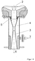
- FIGS. 3 and 4 show special solutions for the coolant supply 5. While in FIG. 3 the coolant is guided over a weir-like arrangement, it flows into the confuser of the venturi quencher 3 as a coolant film in FIG.
- the solutions according to FIGS. 3 and 4 have in common that the coolant is fed in the confuser before the narrowest cross section of the venturi quencher 3. It is accelerated by the gas flow and torn into the smallest droplets in the narrowest cross section.
- the film-like design of the coolant flow simultaneously causes additional cooling of the metal wall in the confusion area of the venturi quencher 3.
- FIG. 5 shows the arrangement of an additional washing and cooling stage 8 downstream of the Venturi quencher 3. This arrangement is particularly advantageous if certain components such as hydrogen halides can be obtained from the raw gas stream for the extraction of hydrohalic acids.
- the separator 6 is then connected to this additional washing and cooling stage 8.
- FIG. 6 shows the arrangement of a controllable venturi quencher 3.
- Rigid venturi quenchers 3 have the disadvantage that the velocities in the venturi quencher 3 also vary with the amount of raw gas fluctuating. If the gas velocity becomes too low, the coolant is broken up only insufficiently. Only larger coolant drops are formed, the surface of which is too small for the desired cooling and washing effect.
- the remaining cross section can be regulated depending on the amount of raw gas, so that the desired speed can be set independently of the amount of raw gas.
- the drive rod In order to prevent raw gas or coolant from escaping, the drive rod is guided through a sealing system 10. In order to keep the mechanical effort low, the quenched raw gas is discharged laterally.
Landscapes
- Chemical & Material Sciences (AREA)
- Engineering & Computer Science (AREA)
- Combustion & Propulsion (AREA)
- Chemical Kinetics & Catalysis (AREA)
- General Chemical & Material Sciences (AREA)
- Oil, Petroleum & Natural Gas (AREA)
- Organic Chemistry (AREA)
- Industrial Gases (AREA)
Abstract
Die Erfindung betrifft ein Verfahren zur Kühlung und Reinigung von
Vergasungsrohgasen, die bei der Vergasung von Brenn-, Rest- und
Abfallstoffen entstehen und bei Normal- und höherem Druck und mit
Temperaturen zwischen 1100- 1600 °C aus dem Vergasungsraum eines
Flugstromvergasers in ein Kühl- oder Quenchsystem eintreten, wobei das
Kühl- und Quenchsystem aus einem Vanturirohr besteht, in dessen engstem
Querschnitt das zu kühlende und zu reinigende Rohgas auf
Geschwindigkeiten zwischen 30 und 150 m/s beschleunigt wird und in das
vor oder im engsten Querschnitt Kühlmittel zugeführt wird sowie
Vorrichtungen zur Durchführung des Verfahrens.

Description
Die Erfindung betrifft ein Verfahren nach dem Oberbegriff des ersten Patentanspruches und eine Vorrichtung zur Durchführung des Verfahrens. Die Erfindung ist überall dort anwendbar, wo der Bedarf zur Kühlung und Reinigung von heißen Vergasungsgasen, die bei der Vergasung von Brenn-, Rest- und Abfallstoffen entstehen, besteht.The invention relates to a method according to the preamble of the first Claim and an apparatus for performing the method. The invention is applicable wherever there is a need for cooling and Cleaning of hot gasification gases, which are used in the gasification of combustion, Residual and waste materials arise.
Unter Brenn-, Rest- und Abfallstoffen verstehen wir dabei konventionelle Brennstoffe wie Kohlen verschiedenen Inkohlungsgrades, Öle aus verschiedenen Aufkommen sowie Gase wie Erdgas, Reststoffe aus der Industrie wie beispielsweise Synthesereststoffe, halogenhaltige Reststoffe wie beispielsweise chlor- oder fuorhaltige Kohlenwasserstoffe, Rückstände der Erdölverarbeitung wie Schweröle und Petrolkoks sowie Abfallstoffe aus Haushalt und Gewerbe wie halogenhaltige Kunststoffe in Mischung mit weiteren Abfällen.We understand fuels, residues and waste materials to be conventional Fuels such as coals of various degrees of carbonization, oils various volumes as well as gases such as natural gas, residues from the Industry such as synthesis residues, halogen-containing residues such as hydrocarbons containing chlorine or fuels, residues oil processing such as heavy oils and petroleum coke as well as waste materials Household and business such as halogen-containing plastics mixed with other waste.
Für die Vergasung von Brenn-, Rest- und Abfallstoffen hat sich die Partialoxidation mit freiem Sauerstoff enthaltenden Vergasungsmittel nach dem Flugstromprinzip bewährt. Die Vergasung erfolgt unter höherem Druck bei Temperaturen zwischen 1000 °C bis 1600 °C. Bekannte Reaktoren zur Durchführung eines solchen Vergasungsprozesses bestehen aus einem oder mehreren nacheinander angeordneten Reaktionsräumen, in denen die zu vergasenden Brenn-, Rest- und Abfallstoffe im Flugstrom, in der Form einer Flammenreaktion zu einem CO- und H2-reichem Rohgas umgesetzt werden. Besteht der Einsatzstoff aus halogenhaltigem Material, sind gleichfalls höhere Konzentrationen an Halogenwasserstoffen im Rohgas. Das mit Temperaturen zwischen 1000 °C und 1600 °C heiße Rohgas tritt nach dem Reaktionsraum in ein Kühl- oder Quenchsystem ein, wo durch direkten Kontakt mit Wasser eine Kühlung und Aufsättigung des Gases erfolgt. Eine Gruppe von technischen Lösungen benutzt dazu ein innenseitig mit einem Wasserfilm gekühltes Rohr, das in ein Wasserbad eintaucht, wie in DD-WP 145 860 und DE ― OS 31 51 483 beschreiben. Dieses Kühlprinzip wird unter anderem ergänzt durch weitere Kühlstufen in Form von zum Beispiel einer Wasserverdüsung am Ende des Tauchrohres. Ein Nachteil dieses Prinzips ist der unabhängig von der Leistung des Reaktors hohe spezifische Wasserverbrauch und der ungenügende Kühl- und Wascheffekt.For the gasification of fuels, residues and waste materials, the partial oxidation with gasification agents containing free oxygen according to the entrained flow principle has proven itself. Gasification takes place under higher pressure at temperatures between 1000 ° C to 1600 ° C. Known reactors for carrying out such a gasification process consist of one or more reaction chambers arranged one after the other, in which the fuels, residues and waste materials to be gasified are converted in the entrained flow in the form of a flame reaction to a CO and H 2 -rich raw gas. If the feed consists of halogen-containing material, there are also higher concentrations of hydrogen halide in the raw gas. The raw gas, which is hot at temperatures between 1000 ° C and 1600 ° C, enters a cooling or quench system after the reaction chamber, where the gas is cooled and saturated by direct contact with water. For this purpose, a group of technical solutions uses a tube which is cooled on the inside with a water film and which is immersed in a water bath, as described in DD-WP 145 860 and DE-OS 31 51 483. This cooling principle is supplemented, among other things, by further cooling stages in the form of, for example, water atomization at the end of the dip tube. A disadvantage of this principle is the high specific water consumption regardless of the performance of the reactor and the insufficient cooling and washing effect.
Zur Überwindung der genannten Nachteile wurden Sprühquenchsysteme entwickelt, bei denen das heiße Vergasungsgas als Freistrahl in einen Freiraum eintritt und die Kühlung durch Eindüsen von Wasser geschieht. Lösungen dieser Art sind beschrieben in DD 288 614 B3 und in DE 36 01 786 C2.Spray quench systems have been used to overcome the disadvantages mentioned developed, in which the hot gasification gas as a free jet into one Free space occurs and the cooling is done by injecting water. Solutions of this type are described in DD 288 614 B3 and in DE 36 01 786 C2.
Der Nachteil dieser Lösungen besteht darin, dass relativ große Quenchräume benötigt werden und der Wascheffekt sich nur ungenügend vollzieht. Durch ungenügende Durchmischung des Gases und sogenannter Strähnenbildung entsteht im Quenchraum ein inhomogenes Temperaturfeld mit heißen und kalten Zonen, was zu unerwünschten Nachreaktionen wie Rußbildung und dem Entstehen toxischer Komponenten führen kann.The disadvantage of these solutions is that they are relatively large Quench rooms are needed and the washing effect is insufficient takes place. Due to insufficient mixing of the gas and so-called Streak formation creates an inhomogeneous temperature field in the quench chamber with hot and cold zones, leading to undesirable post-reactions such as Soot formation and the formation of toxic components can result.
Der Erfindung liegt die Aufgabe zugrunde, heiße Vergasungsgase, die bei der Vergasung von Brenn-, Rest- und Abfallstoffen entstehen und mit Temperaturen von 1100 ― 1600 °C den Vergasungsreaktor verlassen, durch Kontaktierung mit einem Kühlmittel einer Sturzkühlung (Quenchung) zu unterziehen und gleichzeitig einen Waschprozess einzuleiten.The invention is based, hot gasification gases, the task the gasification of fuels, residues and waste materials arise and with Temperatures of 1100 - 1600 ° C leave the gasification reactor through Contact with a coolant for a fall cooling (quenching) undergo and at the same time initiate a washing process.
Erfindungsgemäß wird das den Reaktionsraum verlassende 1100 ― 1600 °C heiße Vergasuntgsgas direkt in ein Rohr, beispielsweise ein Venturirohr, eingeleitet, dem gleichzeitig das Kühlmittel zugeführt wird. Durch die hohe Strömungsgeschwindigkeit im Venturirohr von 50 bis 100 m/s wird das eingespritzte oder anderweitig zugeführte Kühlmittel in feinste Tröpfchen aufgerissen, was zur Bildung sehr großer Oberflächen führt. Da sowohl die Geschwindigkeit der Abkühlung als auch die des Stoffaustausches bei der Waschung des Gases direkt von der gebildeten Oberfläche bestimmt werden, steigen Kühl- und Wascheffekt mit abnehmendem Tropfendurchmesser exponentiell an.According to the invention, the 1100 - 1600 ° C leaving the reaction space hot gasification gas directly into a pipe, for example a Venturi pipe, initiated, which is supplied with the coolant at the same time. Due to the high The flow velocity in the Venturi tube from 50 to 100 m / s will be injected or otherwise supplied coolant in fine droplets torn open, which leads to the formation of very large surfaces. Since both the The rate of cooling as well as that of mass exchange at the Washing of the gas is determined directly from the surface formed cooling and washing effects increase with decreasing Drop diameter exponentially.
Durch extrem schnelle Sturzkühlung (Quenchung) werden Nachreaktionen "eingefroren", so dass es nicht zur Bildung unerwünschter Komponenten kommen kann. Speziell bei der Vergasung halogenhaltiger Rest- und Abfallstoffe besteht die Möglichkeit, als Kühlmittel für die Sturzkühlung Halogenwasserstoffsäure zu benutzen, um auf diese Weise eine genügend hohe Konzentration dieser Wertstoffe zu erreichen.Due to extremely fast fall cooling (quenching), after-reactions become "frozen" so that it does not form unwanted components can come. Especially in the gasification of halogen-containing and Waste materials can be used as coolants for fall cooling Hydrohalic acid to use in this way a sufficient to achieve a high concentration of these valuable substances.
Diese Aufgabe wird durch ein Verfahren mit den kennzeichnenden Merkmalen des ersten Patentanspruches gelöst und mit Vorrichtungen zur Durchführung des Verfahrens. Unteransprüche geben vorteilhafte Ausgestaltungen der Erfindung wieder.This task is accomplished through a process with the characteristic Features of the first claim solved and with devices for Execution of the procedure. Subclaims give advantageous refinements of the invention.
Im Gegensatz zum starren Freiraum- oder Rohrquencher kann der Querschnitt des Venturirohres in Abhängigkeit von der Gasmenge so geregelt werden, dass immer die optimale Geschwindigkeit des Gasstromes eingestellt wird. Besonders bei der Gewinnung von Wertstoffen aus dem Vergasungsgas, wie beispielsweise Salzsäure oder Flusssäure, wie dies beim Einsatz halogenhaltiger Rest- und Abfallstoffe möglich ist, können dem Venturiquenchsystem weitere Waschstufen nachgeschaltet und im Kreislauf verbunden werden.In contrast to the rigid open space or pipe quencher, the Cross-section of the Venturi tube depending on the amount of gas be regulated that always the optimal speed of the gas flow is set. Especially when extracting valuable materials from the Gasification gas such as hydrochloric acid or hydrofluoric acid such as this is possible when using halogen-containing residues and waste materials Venturi quench system downstream of further washing stages and in the cycle get connected.
Die Erfindung wird im Folgenden an einem Ausführungsbeispiel mit
6 Figuren näher erläutert.
Die Figuren zeigen:
- Fig. 1
- Anordnung von Vergasungsreaktor und Venturiquencher,
- Fig. 2
- konstruktive Ausgestaltung des Venturiquenchers mit Düsen und Stutzen,
- Fig. 3/4
- weitere Lösungen zur Kühlmittelzuführung,
- Fig. 5
- Anordnung einer zusätzlichen Wasch- und Kühlstufe nach dem Venturiquencher,
- Fig. 6
- Ausführungsbeispiel für einen regelbaren Venturiquencher.
The figures show:
- Fig. 1
- Arrangement of gasification reactor and venturi quencher,
- Fig. 2
- constructive design of the venturi quencher with nozzles and nozzles,
- Fig. 3/4
- further solutions for coolant supply,
- Fig. 5
- Arrangement of an additional washing and cooling stage after the Venturi quencher,
- Fig. 6
- Exemplary embodiment for a controllable Venturi quencher.
Die Figur 1 zeigt die Anordnung von Vergasungsreaktor 2 und
Venturiquencher 3. Der Brenn-, Abfall- oder Reststoff wird gemeinsam mit
Sauerstoff über Brenner 1 dem Vergasungsraum 2 zugeführt und in einer
Flammenreaktion zu CO- und H2-reichem Vergasungsgas umgesetzt. Das
1100- 1600 °C heiße Vergasungsgas gelangt aus dem Vergasungsraum 2
in den Venturiquencher 3, in dessen engstem Querschnitt das zu kühlende
und zu reinigende heiße Vergasungsgas auf Geschwindigkeiten zwischen 50
und 100 m/s beschleunigt wird. Über den Stutzen 7 wird Kühlmittel zugeführt,
das im Doppelmantel 4 des Venturiquenchers nach oben strömt und dabei
die Metallwandung kühlt Das Kühlmittel gelangt über Zuführungsöffnungen
5, die auch als Düsen ausgebildet sein können, in den heißen Gasstrom und
wird in kleine Tröpfchen aufgerissen, die eine große spezifische Oberfläche
bilden und zu einer extrem schnellen Abkühlung des heißen
Vergasungsgases führen. Mitgerissene, bei den hohen Gastemperaturen
flüssige Schlackepartikel werden gleichfalls gekühlt, verfestigt und mit dem
Gasstrom weggeführt. Feste Partikel wie Ruß oder andere nicht
geschmolzene Bestandteile werden benetzt und im nachfolgenden
Abscheider 6 gemeinsam mit Wassertröpfchen aus dem gekühlten Gasstrom
abgeschieden. Der Abscheider 6 kann nach dem Stand der Technik
beispielsweise als Fliehkraft- oder Lamellenabscheider ausgebildet sein. Als
kühlmedium wird gewöhnlich Wasser verwendet, das nach einer
Zwischenreinigung durch Staubabscheidung im Kreislauf geführt wird.
Gleichfalls werden Kondensate verwendet, die im nachgeschalteten
technologischen Teil der weiteren Gaskühlung und -reinigung anfallen. Bei
Einsatz halogenhaltiger Rest- und Abfallstoffe mit dem Ziel der Gewinnung
von Halogenwasserstoffsäuren kann als Kühl- und Waschmittel über den
Stutzen 7 und die Zuführungsöffnungen 5 bereits Halogenwasserstoffsäure
zugeführt werden, um während des gleichzeitig ablaufenden
Waschprozesses im Venturiquencher und nachgeschalteten Stufen eine
genügend hohe Säurekonzentration zu erhalten. Figure 1 shows the arrangement of
Die Figur 2 zeigt eine bestimmte konstruktive Ausgestaltung der
erfinderischen Lösung, bei der das über den Stutzen 7 zugeführte Kühlmittel
zur Kühlung der Metallwandung des Venturirohres zunächst nach unten
geleitet, umgelenkt und über den doppelmantelähnlichen Raum 4 im engsten
Querschnitt des Venturirohres 3 über die Zuführungsöffnung 5 dem aus der
Vergasungskammer 2 kommenden heißen Gasstrom aufgegeben wird. Figure 2 shows a certain constructive embodiment of the inventive solution, in which the coolant supplied via the
Die Figuren 3 und 4 zeigen besondere Lösungen der Kühlmittelzufuhr 5.
Während in Figur 3 das Kühlmittel über eine wehrähnliche Anordnung geführt
wird, fließt es in Figur 4 als Kühlmittelfilm in den Konfusor des
Venturiquenchers 3 ein. Den Lösungen nach den Figuren 3 und 4 ist
gemeinsam, dass das Kühlmittel vor dem engsten Querschnitt des
Venturiquenchers 3 im Konfusor zugeführt wird. Es wird vom Gasstrom
beschleunigt und im engsten Querschnitt zu feinste Tröpfchen aufgerissen.
Die filmartige Ausbildung des Kühlmittelstromes bewirkt gleichzeitig eine
zusätzliche Kühlung der Metallwandung im Konfusionsbereich des
Venturiquenchers 3.FIGS. 3 and 4 show special solutions for the
Die Figur 5 zeigt die Anordnung einer zusätzlichen Wasch- und Kühlstufe 8
hinter dem Venturiquencher 3. Diese Anordnung ist besonders vorteilhaft,
wenn bestimmte Komponenten wie Halogenwasserstoffe zur Gewinnung von
Halogenwasserstoffsäuren aus dem Rohgasstrom zu gewinnen sind. Der
Abscheider 6 ist dann dieser zusätzlichen Wasch- und Kühlstufe 8
nachgeschaltet. FIG. 5 shows the arrangement of an additional washing and
Die Figur 6 zeigt die Anordnung eines regelbaren Venturiquenchers 3. Starre
Venturiquencher 3 haben den Nachteil, dass mit schwankender
Rohgasmenge gleichfalls die Geschwindigkeiten im Venturiquencher 3
unterschiedlich hoch sind. Wird die Gasgeschwindigkeit zu niedrig, wird das
Kühlmittel nur in ungenügender Weise zerteilt. Es bilden sich nur größere
Kühlmitteltropfen, deren Oberfläche für den gewünschten Kühl- und
Wascheffekt zu gering ist. Durch Anordnung eines verfahrbaren Kegels 9
lässt sich der verbleibende Querschnitt in Abhängigkeit von der
Rohgasmenge regeln, so dass unabhängig von der Rohgasmenge die
gewünschte Geschwindigkeit eingestellt werden kann. Um ein Austreten von
Rohgas oder Kühlmittel zu verhindern, wird die Antriebsstange durch ein
Abdichtungssystem 10 geführt. Um den mechanischen Aufwand gering zu
halten, wird das gequenchte Rohgas seitlich abgeführt. FIG. 6 shows the arrangement of a
- 11
- Brennerburner
- 22nd
- VergasungsraumGasification room
- 33rd
- VenturirohrVenturi tube
- 44th
- DoppelmantelDouble jacket
- 55
- Zuführung des KühlmittelsCoolant supply
- 66
- AbscheiderSeparator
- 77
- StutzenSupport
- 88th
- Wasch- und KühlstufeWashing and cooling stage
- 99
- Verfahrbarer KegelMovable cone
- 1010th
- AbdichtungssystemSealing system
Claims (14)
dadurch gekennzeichnet, dass
das Rohgas nach dem Beschleunigungs- und Waschprozess einem zusätzlichen Wasch- und Kühlprozess mit einer anschließenden Abscheidung unterzogen wird.Method according to one of claims 1 to 3,
characterized in that
the raw gas is subjected to an additional washing and cooling process with a subsequent separation after the acceleration and washing process.
dadurch gekennzeichnet, dass
als Kühlmittel im Rohr die abgetrennte Flüssigkeit des Abscheiders oder der nachgeschalteten Wasch- und Kühlstufe zugeführt wird. Method according to one of claims 1 to 4,
characterized in that
the separated liquid of the separator or the downstream washing and cooling stage is supplied as a coolant in the pipe.
nach dem Vergasungsraum (2) als Rohr zur Beschleunigung des Rohgases ein Venturirohr (3) angeordnet ist, welches an seiner engsten Stelle Zuführöffnungen (5, 7) für eine Kühlflüssigkeit aufweist.Device for carrying out a method according to one of claims 1 to 5, characterized in that
a venturi tube (3) is arranged after the gasification chamber (2) as a tube for accelerating the raw gas and has supply openings (5, 7) for a cooling liquid at its narrowest point.
dadurch gekennzeichnet, dass
das Venturirohr (3) als Doppelmantel (4) ausgeführt ist und das Kühlmittel über den Doppelmantel (4) dem Venturirohr (3) zugeführt wird.Device according to one of claims 6 and 7,
characterized in that
the venturi tube (3) is designed as a double jacket (4) and the coolant is fed to the venturi tube (3) via the double jacket (4).
dadurch gekennzeichnet, dass
die Zuführung (5) des Kühlmittels in das Venturirohr (3) über Düsen erfolgt.Device according to one of claims 6 to 8,
characterized in that
the coolant is fed (5) into the venturi tube (3) via nozzles.
die Zuführung (5) des Kühlmittels über einen Überlauf erfolgt.Device for carrying out a method according to one of claims 1 to 5, characterized in that
the coolant is supplied (5) via an overflow.
die Zuführung (5) des Kühlmittels über durch einen mittels Spalt erzeugten Kühlmittelfilm erfolgt.Device for carrying out a method according to claims 1 to 5, characterized in that
the coolant is supplied (5) via a coolant film produced by means of a gap.
dadurch gekennzeichnet, dass
dem Venturirohr (3) eine zusätzliche Wasch- und Kühlstufe (8) nachgeschaltet ist und das gekühlte und gewaschene Gas zum Abscheider (6) gelangt. Device according to one of claims 6 to 11,
characterized in that
The Venturi tube (3) is followed by an additional washing and cooling stage (8) and the cooled and washed gas reaches the separator (6).
dadurch gekennzeichnet, dass
das Kühlmittel des Venturirohres (3) abgetrennte Flüssigkeit des Abscheiders (6) oder der nachgeschalteten Wasch- und Kühlstufe (8) über Rohrleitungen zugeführt wird.Device according to one of claims 6 to 12,
characterized in that
the coolant of the Venturi tube (3) separated liquid of the separator (6) or the downstream washing and cooling stage (8) is fed via pipes.
dadurch gekennzeichnet, dass
der wirksame Querschnitt des Venturirohres (3) mittels verfahrbarem Kegel (9) im Venturirohr (3) eingestellt wird.Device according to one of claims 6 to 13,
characterized in that
the effective cross section of the venturi tube (3) is set by means of a movable cone (9) in the venturi tube (3).
Applications Claiming Priority (2)
| Application Number | Priority Date | Filing Date | Title |
|---|---|---|---|
| DE19952754 | 1999-11-02 | ||
| DE1999152754 DE19952754A1 (en) | 1999-11-02 | 1999-11-02 | Method and device for cooling and cleaning gasification gases |
Publications (2)
| Publication Number | Publication Date |
|---|---|
| EP1097984A2 true EP1097984A2 (en) | 2001-05-09 |
| EP1097984A3 EP1097984A3 (en) | 2002-12-18 |
Family
ID=7927681
Family Applications (1)
| Application Number | Title | Priority Date | Filing Date |
|---|---|---|---|
| EP00123621A Withdrawn EP1097984A3 (en) | 1999-11-02 | 2000-10-28 | Process and plant for the cooling and cleaning of gasification gases |
Country Status (3)
| Country | Link |
|---|---|
| EP (1) | EP1097984A3 (en) |
| BR (1) | BR0005203A (en) |
| DE (1) | DE19952754A1 (en) |
Cited By (9)
| Publication number | Priority date | Publication date | Assignee | Title |
|---|---|---|---|---|
| AT505751B1 (en) * | 2008-01-23 | 2009-04-15 | Austrian Energy & Environment | GAS CHANNEL WITH EMERGENCY SEQUENCE DEVICE AND METHOD FOR AVOIDING CORROSION AT THE EMERGENCY SEQUENCE DEVICE |
| WO2010012404A3 (en) * | 2008-07-29 | 2010-05-27 | Uhde Gmbh | Slag discharge from reactor for synthesis gas production |
| CN101842467A (en) * | 2007-09-18 | 2010-09-22 | 犹德有限公司 | Gasification reactor and method for entrained-flow gasification |
| WO2014052945A3 (en) * | 2012-09-30 | 2014-07-31 | Dow Global Technologies, Llc | Weir quench and processes incorporating the same |
| US8907149B2 (en) | 2011-05-31 | 2014-12-09 | Dow Global Technologies Llc | Process for the production of chlorinated propenes |
| CN104220565A (en) * | 2012-02-03 | 2014-12-17 | 蒂森克虏伯工业解决方案股份公司 | Apparatus and process for the gasification of solid hydrocarbonaceous fuels in particulate form in entrained gas streams |
| US9050551B2 (en) | 2011-10-28 | 2015-06-09 | American Air Liquide, Inc. | Supersonic venturi scrubber |
| US9067855B2 (en) | 2011-11-21 | 2015-06-30 | Dow Global Technologies Llc | Process for the production of chlorinated alkanes |
| US10065157B2 (en) | 2012-10-26 | 2018-09-04 | Blue Cube Ip Llc | Mixer and processes incorporating the same |
Families Citing this family (28)
| Publication number | Priority date | Publication date | Assignee | Title |
|---|---|---|---|---|
| US20080190026A1 (en) | 2006-12-01 | 2008-08-14 | De Jong Johannes Cornelis | Process to prepare a mixture of hydrogen and carbon monoxide from a liquid hydrocarbon feedstock containing a certain amount of ash |
| US8052864B2 (en) | 2006-12-01 | 2011-11-08 | Shell Oil Company | Process to prepare a sweet crude |
| US9051522B2 (en) | 2006-12-01 | 2015-06-09 | Shell Oil Company | Gasification reactor |
| US8475546B2 (en) | 2008-12-04 | 2013-07-02 | Shell Oil Company | Reactor for preparing syngas |
| US8960651B2 (en) | 2008-12-04 | 2015-02-24 | Shell Oil Company | Vessel for cooling syngas |
| DE102009022186A1 (en) | 2009-05-20 | 2010-11-25 | Uhde Gmbh | Device for influencing the flow in a connecting pipe coal gasification reactor / gas cooler |
| JP5782038B2 (en) | 2009-10-09 | 2015-09-24 | ダウ グローバル テクノロジーズ エルエルシー | Isothermal multitubular reactor and process incorporating the reactor |
| EP2739596B1 (en) | 2011-08-07 | 2019-05-01 | Blue Cube IP LLC | Process for the production of chlorinated propenes |
| US9284239B2 (en) | 2011-12-02 | 2016-03-15 | Blue Cube Ip Llc | Process for the production of chlorinated alkanes |
| JP6059246B2 (en) | 2011-12-02 | 2017-01-11 | ブルー キューブ アイピー エルエルシー | Method for producing chlorinated alkane |
| JP6170068B2 (en) | 2011-12-13 | 2017-07-26 | ブルー キューブ アイピー エルエルシー | Method for producing chlorinated propane and propene |
| EP2794528B1 (en) | 2011-12-22 | 2020-02-26 | Blue Cube IP LLC | Process for the production of tetrachloromethane |
| BR112014015123A2 (en) | 2011-12-23 | 2017-06-13 | Dow Global Technologies Llc | process for the production of one or more alkenes or aromatic compounds |
| CN104755448A (en) | 2012-09-20 | 2015-07-01 | 陶氏环球技术有限公司 | Process for the production of chlorinated propenes |
| US9321707B2 (en) | 2012-09-20 | 2016-04-26 | Blue Cube Ip Llc | Process for the production of chlorinated propenes |
| WO2014100066A1 (en) | 2012-12-18 | 2014-06-26 | Dow Global Technologies, Llc | Process for the production of chlorinated propenes |
| CA2894168C (en) | 2012-12-19 | 2018-04-24 | Dow Global Technologies Llc | Process for the production of chlorinated propenes |
| CA2901450A1 (en) | 2013-02-27 | 2014-09-04 | Blue Cube Ip Llc | Process for the production of chlorinated propenes |
| US9403741B2 (en) | 2013-03-09 | 2016-08-02 | Blue Cube Ip Llc | Process for the production of chlorinated alkanes |
| DE102013217450A1 (en) | 2013-09-02 | 2015-03-05 | Siemens Aktiengesellschaft | Combined quench and wash system with guide tube for an entrainment gasification reactor |
| DE102013217453A1 (en) | 2013-09-02 | 2015-03-05 | Siemens Aktiengesellschaft | Combined quench and wash system with double central tube for an entrainment gasification reactor |
| DE102013217447A1 (en) | 2013-09-02 | 2015-03-05 | Siemens Aktiengesellschaft | Combined quench and wash system with inner jacket for an entrainment gasification reactor |
| DE102013218839A1 (en) | 2013-09-19 | 2015-03-19 | Siemens Aktiengesellschaft | Nozzle passage through the pipe screen of a combined quench and wash system for an entrainment gasification reactor |
| DE102013218830A1 (en) | 2013-09-19 | 2015-03-19 | Siemens Aktiengesellschaft | Divided central tube of a combined quench and wash system for an entrainment gasification reactor |
| DE102013218831A1 (en) | 2013-09-19 | 2015-03-19 | Siemens Aktiengesellschaft | Central tube with surface body of a combined quench and wash system for an entrainment gasification reactor |
| DE102014201890A1 (en) | 2014-02-03 | 2015-08-06 | Siemens Aktiengesellschaft | Cooling and washing of a raw gas from the entrained flow gasification |
| DE102016211869A1 (en) | 2016-06-30 | 2018-01-04 | Siemens Aktiengesellschaft | Combined free space quench for a high flow entrainment gasification reactor with quench and scrubbing stage |
| DE102016211870A1 (en) | 2016-06-30 | 2018-01-04 | Siemens Aktiengesellschaft | Free space quench for a large flow entrainment gasification reactor |
Family Cites Families (12)
| Publication number | Priority date | Publication date | Assignee | Title |
|---|---|---|---|---|
| GB904917A (en) * | 1960-05-30 | 1962-09-05 | Svenska Flaektfabriken Ab | Improvements in wet separators |
| US3456928A (en) * | 1967-05-24 | 1969-07-22 | Chemical Construction Corp | Combined blast furnace scrubber and dust catcher |
| US3638925A (en) * | 1969-07-22 | 1972-02-01 | Chemical Construction Corp | Adjustable annular venturi scrubber |
| US3607157A (en) * | 1969-07-23 | 1971-09-21 | Texaco Inc | Synthesis gas from petroleum coke |
| US3841061A (en) * | 1972-11-24 | 1974-10-15 | Pollution Ind Inc | Gas cleaning apparatus |
| US3963457A (en) * | 1974-11-08 | 1976-06-15 | Koppers Company, Inc. | Coal gasification process |
| US4252543A (en) * | 1979-07-25 | 1981-02-24 | General Electric Company | Process for quenching and cleaning a fuel gas mixture |
| DE3338725A1 (en) * | 1983-02-22 | 1984-08-23 | Brennstoffinstitut Freiberg, Ddr 9200 Freiberg | DEVICE FOR REMOVING LIQUID SLAG AND GAS |
| FR2562084B1 (en) * | 1984-04-03 | 1986-08-08 | Elf France | PROCESS FOR PURIFYING GASES OF GAS |
| SE454327B (en) * | 1984-10-17 | 1988-04-25 | Skf Steel Eng Ab | KIT AND INSTALLATION FOR COOLING AND PURIFICATION OF GAS FROM DUST |
| DD288614B3 (en) * | 1989-10-18 | 1993-03-25 | Noell Dbi Energie Entsorgung | REACTOR FOR FLOW CURING |
| SE9001957L (en) * | 1990-05-31 | 1991-12-01 | Chemrec Ab | Purification of process gas from partial combustion of black liquor |
-
1999
- 1999-11-02 DE DE1999152754 patent/DE19952754A1/en not_active Withdrawn
-
2000
- 2000-10-28 EP EP00123621A patent/EP1097984A3/en not_active Withdrawn
- 2000-10-31 BR BR0005203A patent/BR0005203A/en not_active Application Discontinuation
Cited By (21)
| Publication number | Priority date | Publication date | Assignee | Title |
|---|---|---|---|---|
| US9890341B2 (en) | 2007-09-18 | 2018-02-13 | Thyssenkrupp Industrial Solutions Ag | Gasification reactor and process for entrained-flow gasification |
| CN101842467A (en) * | 2007-09-18 | 2010-09-22 | 犹德有限公司 | Gasification reactor and method for entrained-flow gasification |
| AU2008300900B2 (en) * | 2007-09-18 | 2013-03-21 | Thyssenkrupp Uhde Gmbh | Gasification reactor and method for entrained-flow gasification |
| CN101842467B (en) * | 2007-09-18 | 2013-09-25 | 犹德有限公司 | Gasification reactor and method for entrained-flow gasification |
| RU2495912C2 (en) * | 2007-09-18 | 2013-10-20 | Уде Гмбх | Gasification reactor and method of gasification in flow |
| US9290709B2 (en) | 2007-09-18 | 2016-03-22 | Thyssenkrupp Industrial Solutions Ag | Gasification reactor and process for entrained-flow gasification |
| AT505751B1 (en) * | 2008-01-23 | 2009-04-15 | Austrian Energy & Environment | GAS CHANNEL WITH EMERGENCY SEQUENCE DEVICE AND METHOD FOR AVOIDING CORROSION AT THE EMERGENCY SEQUENCE DEVICE |
| AP3484A (en) * | 2008-07-29 | 2015-12-31 | Uhde Gmbh | Slag discharge from reactor for synthesis gas production |
| RU2508392C2 (en) * | 2008-07-29 | 2014-02-27 | Уде Гмбх | Slime dumping from reactor for production of synthesis gas |
| US9102883B2 (en) | 2008-07-29 | 2015-08-11 | Thyssenkrupp Uhde Gmbh | Slag discharge from reactor for synthesis gas production |
| WO2010012404A3 (en) * | 2008-07-29 | 2010-05-27 | Uhde Gmbh | Slag discharge from reactor for synthesis gas production |
| US8907149B2 (en) | 2011-05-31 | 2014-12-09 | Dow Global Technologies Llc | Process for the production of chlorinated propenes |
| US9050551B2 (en) | 2011-10-28 | 2015-06-09 | American Air Liquide, Inc. | Supersonic venturi scrubber |
| US9067855B2 (en) | 2011-11-21 | 2015-06-30 | Dow Global Technologies Llc | Process for the production of chlorinated alkanes |
| CN104220565A (en) * | 2012-02-03 | 2014-12-17 | 蒂森克虏伯工业解决方案股份公司 | Apparatus and process for the gasification of solid hydrocarbonaceous fuels in particulate form in entrained gas streams |
| CN104220565B (en) * | 2012-02-03 | 2017-05-24 | 蒂森克虏伯工业解决方案股份公司 | Apparatus and process for the gasification of solid hydrocarbonaceous fuels in particulate form in entrained gas streams |
| CN104718020A (en) * | 2012-09-30 | 2015-06-17 | 陶氏环球技术有限公司 | Weir quench and processes incorporating the same |
| WO2014052945A3 (en) * | 2012-09-30 | 2014-07-31 | Dow Global Technologies, Llc | Weir quench and processes incorporating the same |
| US9795941B2 (en) | 2012-09-30 | 2017-10-24 | Blue Cube Ip Llc | Weir quench and processes incorporating the same |
| JP2015535739A (en) * | 2012-09-30 | 2015-12-17 | ダウ グローバル テクノロジーズ エルエルシー | Cough quench and method incorporating it |
| US10065157B2 (en) | 2012-10-26 | 2018-09-04 | Blue Cube Ip Llc | Mixer and processes incorporating the same |
Also Published As
| Publication number | Publication date |
|---|---|
| BR0005203A (en) | 2002-12-31 |
| DE19952754A1 (en) | 2001-05-10 |
| EP1097984A3 (en) | 2002-12-18 |
Similar Documents
| Publication | Publication Date | Title |
|---|---|---|
| EP1097984A2 (en) | Process and plant for the cooling and cleaning of gasification gases | |
| DE4240196C2 (en) | Process for cooling and cleaning gas containing ultrafine particles, in particular top gas or generator gas, and device for carrying it out | |
| DE102006059149B4 (en) | Residual flow reactor for the gasification of solid and liquid energy sources | |
| DE3121206C2 (en) | Solid waste gasification method | |
| WO2009036985A1 (en) | Gasification reactor and method for entrained-flow gasification | |
| DE102005035921B4 (en) | Process for the endothermic gasification of carbon | |
| DE102014201890A1 (en) | Cooling and washing of a raw gas from the entrained flow gasification | |
| DE102007042543A1 (en) | Process and apparatus for treating laden hot gas | |
| DE102007044726A1 (en) | Synthesis gas producing method, involves drying and cooling synthesis gas in chamber, arranging water bath below another chamber, and extracting produced and cooled synthesis gas from pressure container below or lateral to latter chamber | |
| CH644149A5 (en) | METHOD AND DEVICE FOR GASIFYING COAL. | |
| DD145860A3 (en) | METHOD AND DEVICE FOR COMPRESSING GASING GASES | |
| DE3020684A1 (en) | IMPROVED METHOD FOR GASIFYING CARBONATED SUBSTANCES | |
| DE3205346C2 (en) | Two-stage carburetor | |
| DD297661A5 (en) | APPENDIX FOR THE PRODUCTION OF A PRODUCT GAS FROM A PARTICULATE CARBON FUEL | |
| DE2104478A1 (en) | Method and device for cooling hot media | |
| DE1939776A1 (en) | Process and device for cleaning high-tension gases | |
| DE3338725A1 (en) | DEVICE FOR REMOVING LIQUID SLAG AND GAS | |
| EP0632122B1 (en) | Process and device for separating slag droplets from hot gases from combustion or gasification of solid or liquid fuels | |
| DD265051A3 (en) | DEVICE FOR DISTRIBUTING A SOLID-STORED GAS IN A WASH FLUID | |
| DE102008012734A1 (en) | Method for obtaining synthesis gas by gasification of liquid or finely comminuted solid fuels, involves producing synthesis gas in reaction chamber arranged over reactor, in which ingredients are supplied | |
| EP2516684A1 (en) | Method and device for providing reduction gas from generator gas | |
| DE102014203639A1 (en) | Dust separation from the raw gas of an entrainment gasification | |
| LU83212A1 (en) | METHOD FOR CONTINUOUSLY BLOWING IN REDUCTION AGENTS CONTAINING ASHTIC CHARCOAL INTO THE RACK OF A BLAST FURNACE | |
| DE897310C (en) | Method and device for the gasification of fuels | |
| DE102010045481A1 (en) | Device for cooling clinker-containing hot gas flow and for separating clinker from hot gas flow of entrained flow gasifier system of biomass gasifier, has passage openings whose dimensions increase with immersion depth at coolant bath |
Legal Events
| Date | Code | Title | Description |
|---|---|---|---|
| PUAI | Public reference made under article 153(3) epc to a published international application that has entered the european phase |
Free format text: ORIGINAL CODE: 0009012 |
|
| AK | Designated contracting states |
Kind code of ref document: A2 Designated state(s): AT BE CH CY DE DK ES FI FR GB GR IE IT LI LU MC NL PT SE |
|
| AX | Request for extension of the european patent |
Free format text: AL;LT;LV;MK;RO;SI |
|
| PUAL | Search report despatched |
Free format text: ORIGINAL CODE: 0009013 |
|
| AK | Designated contracting states |
Kind code of ref document: A3 Designated state(s): AT BE CH CY DE DK ES FI FR GB GR IE IT LI LU MC NL PT SE |
|
| AX | Request for extension of the european patent |
Free format text: AL;LT;LV;MK;RO;SI |
|
| RIC1 | Information provided on ipc code assigned before grant |
Free format text: 7C 10K 1/04 A, 7C 10K 1/06 B |
|
| STAA | Information on the status of an ep patent application or granted ep patent |
Free format text: STATUS: THE APPLICATION HAS BEEN WITHDRAWN |
|
| 18W | Application withdrawn |
Effective date: 20030201 |