EP1091696B1 - Device for inserting a prosthetic knee - Google Patents
Device for inserting a prosthetic knee Download PDFInfo
- Publication number
- EP1091696B1 EP1091696B1 EP98928043A EP98928043A EP1091696B1 EP 1091696 B1 EP1091696 B1 EP 1091696B1 EP 98928043 A EP98928043 A EP 98928043A EP 98928043 A EP98928043 A EP 98928043A EP 1091696 B1 EP1091696 B1 EP 1091696B1
- Authority
- EP
- European Patent Office
- Prior art keywords
- femur
- axis
- pivot
- base part
- adjustment device
- Prior art date
- Legal status (The legal status is an assumption and is not a legal conclusion. Google has not performed a legal analysis and makes no representation as to the accuracy of the status listed.)
- Expired - Lifetime
Links
- 210000003127 knee Anatomy 0.000 title description 9
- 210000000689 upper leg Anatomy 0.000 claims abstract description 122
- 238000002271 resection Methods 0.000 claims abstract description 28
- 210000000629 knee joint Anatomy 0.000 claims abstract description 16
- 238000002513 implantation Methods 0.000 claims abstract description 6
- 238000005520 cutting process Methods 0.000 claims description 34
- 210000002414 leg Anatomy 0.000 claims description 20
- 210000000988 bone and bone Anatomy 0.000 claims description 12
- 238000004873 anchoring Methods 0.000 claims description 5
- 238000005259 measurement Methods 0.000 claims 1
- 210000002303 tibia Anatomy 0.000 description 72
- 239000000523 sample Substances 0.000 description 16
- 238000006073 displacement reaction Methods 0.000 description 12
- 239000007943 implant Substances 0.000 description 12
- 238000000034 method Methods 0.000 description 7
- 210000003041 ligament Anatomy 0.000 description 5
- 239000002184 metal Substances 0.000 description 3
- 229910052751 metal Inorganic materials 0.000 description 3
- 229910000639 Spring steel Inorganic materials 0.000 description 2
- 238000005452 bending Methods 0.000 description 2
- 238000005553 drilling Methods 0.000 description 2
- 230000036512 infertility Effects 0.000 description 2
- 238000003780 insertion Methods 0.000 description 2
- 230000037431 insertion Effects 0.000 description 2
- 210000001699 lower leg Anatomy 0.000 description 2
- 210000003205 muscle Anatomy 0.000 description 2
- 238000001356 surgical procedure Methods 0.000 description 2
- 241000309551 Arthraxon hispidus Species 0.000 description 1
- 208000005189 Embolism Diseases 0.000 description 1
- 229910000831 Steel Inorganic materials 0.000 description 1
- 241001422033 Thestylus Species 0.000 description 1
- 208000007536 Thrombosis Diseases 0.000 description 1
- 241001227561 Valgus Species 0.000 description 1
- 241000469816 Varus Species 0.000 description 1
- 238000011882 arthroplasty Methods 0.000 description 1
- 230000002457 bidirectional effect Effects 0.000 description 1
- 210000004439 collateral ligament Anatomy 0.000 description 1
- 239000002131 composite material Substances 0.000 description 1
- 239000012141 concentrate Substances 0.000 description 1
- 230000000694 effects Effects 0.000 description 1
- 238000011067 equilibration Methods 0.000 description 1
- 210000002683 foot Anatomy 0.000 description 1
- 230000005484 gravity Effects 0.000 description 1
- 230000000977 initiatory effect Effects 0.000 description 1
- 238000007689 inspection Methods 0.000 description 1
- 231100000518 lethal Toxicity 0.000 description 1
- 230000001665 lethal effect Effects 0.000 description 1
- 238000003754 machining Methods 0.000 description 1
- 150000002739 metals Chemical class 0.000 description 1
- 238000002559 palpation Methods 0.000 description 1
- 210000004417 patella Anatomy 0.000 description 1
- 230000001575 pathological effect Effects 0.000 description 1
- 230000035515 penetration Effects 0.000 description 1
- 238000003825 pressing Methods 0.000 description 1
- 230000000284 resting effect Effects 0.000 description 1
- 238000000926 separation method Methods 0.000 description 1
- 210000004872 soft tissue Anatomy 0.000 description 1
- 239000007787 solid Substances 0.000 description 1
- 238000003892 spreading Methods 0.000 description 1
- 239000010959 steel Substances 0.000 description 1
- 238000004804 winding Methods 0.000 description 1
Images


Classifications
-
- A—HUMAN NECESSITIES
- A61—MEDICAL OR VETERINARY SCIENCE; HYGIENE
- A61B—DIAGNOSIS; SURGERY; IDENTIFICATION
- A61B17/00—Surgical instruments, devices or methods
- A61B17/14—Surgical saws
- A61B17/15—Guides therefor
- A61B17/154—Guides therefor for preparing bone for knee prosthesis
-
- A—HUMAN NECESSITIES
- A61—MEDICAL OR VETERINARY SCIENCE; HYGIENE
- A61B—DIAGNOSIS; SURGERY; IDENTIFICATION
- A61B17/00—Surgical instruments, devices or methods
- A61B17/14—Surgical saws
- A61B17/15—Guides therefor
- A61B17/154—Guides therefor for preparing bone for knee prosthesis
- A61B17/155—Cutting femur
-
- A—HUMAN NECESSITIES
- A61—MEDICAL OR VETERINARY SCIENCE; HYGIENE
- A61B—DIAGNOSIS; SURGERY; IDENTIFICATION
- A61B90/00—Instruments, implements or accessories specially adapted for surgery or diagnosis and not covered by any of the groups A61B1/00 - A61B50/00, e.g. for luxation treatment or for protecting wound edges
- A61B90/39—Markers, e.g. radio-opaque or breast lesions markers
- A61B2090/3904—Markers, e.g. radio-opaque or breast lesions markers specially adapted for marking specified tissue
- A61B2090/3916—Bone tissue
-
- A—HUMAN NECESSITIES
- A61—MEDICAL OR VETERINARY SCIENCE; HYGIENE
- A61B—DIAGNOSIS; SURGERY; IDENTIFICATION
- A61B90/00—Instruments, implements or accessories specially adapted for surgery or diagnosis and not covered by any of the groups A61B1/00 - A61B50/00, e.g. for luxation treatment or for protecting wound edges
- A61B90/39—Markers, e.g. radio-opaque or breast lesions markers
- A61B2090/3983—Reference marker arrangements for use with image guided surgery
Definitions
- the present invention relates to a device which allows a surgeon to Implantation of a total knee joint endoprosthesis Resection of the femur and tibia in an extremely precise manner Way to perform.
- a total knee joint endoprosthesis consists of an am Femur and a component attached to the tibia. Before the total joint arthroplasty can be implanted the adjacent bone areas of the femur and the Tibia to be resected appropriately Norman contact surfaces according to the geometry of the To create endoprostheses. Usually the Frontals of the tibia and femur resected. At least the femur also receives at least one so-called dorsal and a ventral incision, because the Femoral part of total endoprostheses usually U-shaped is designed. The generally from manufacturers of Instruments offered to knee prostheses do not allow the required bone cuts on the femur and on the tibia with the required accuracy.
- Such an instrument is from EP 0 322 363 A1 known.
- This set of instruments uses a Extra medullary means for aligning the tibia and femur (extramedullary alignment system) and has the disadvantage that the alignment of the femur only with the help of a X-ray apparatus can be determined.
- the Attachment of the reference system for the bone cuts after A sense of proportion, with the reference system also providing access to Operating field difficult.
- Another set of instruments is from EP 0 691 110 A2 known.
- This set of instruments uses a intramedullary means to align the tibia and femur (intramedullary alignment system) and has the disadvantage on that for mutual fixation of the tibia and femur A guide spike is required, which is in the Tibial or femoral marrow space is introduced. This intervention in the medullary can cause thrombosis or embolism, what can be lethal.
- the object of the present invention is a device to determine resection cuts on the femur and on the tibia to prepare a Implantation of a total knee joint endoprosthesis create which is easily and reliably reproducible is to be carried out.
- the device according to the invention comprises in one advantageous embodiment, a reference device consisting essentially of a detachable in the distal Area of the femur lockable base part and a articulated and / or slidable with the base part connected reference body, which is a coordinate system X, Y, Z has determining means, the orientation of the reference body with respect to the femur is positionable and with a between the Acting reference body and the base part Actuating means for fixing their mutual position is provided, and wherein the coordinate system X, Y, Z determining means for the aligned fastening of Machining aids such as a cutting jig, one Base bar or a measuring device are configured.
- a reference device consisting essentially of a detachable in the distal Area of the femur lockable base part and a articulated and / or slidable with the base part connected reference body, which is a coordinate system X, Y, Z has determining means, the orientation of the reference body with respect
- the reference device comes with a variety of differently designed means on the femur attachable, for example with bone screws, or the femur at least partially comprehensive gripping arms, which can also have spines for better anchoring, which penetrate the femur.
- the device according to the invention comprises in one Another advantageous embodiment is an extra medullary and releasably attachable in the distal area of the femur Reference device, its orientation with respect to the femur is positionable exactly, as well as an extramedullary and Tibial splint can be detachably attached to the tibia, the Alignment of the tibia splint with respect to the tibia is positionable, and a the reference device as well as releasably firmly connecting the tibia splint Fastening device.
- This embodiment according to the invention has the advantage on that the tibia with respect to the femur in an exact defined position and can then be fixed. Therefore, the direction of the resection cuts can the tibia via the cutting device attached to the femur be specified.
- the position of the tibia can be related the femur can be adjusted precisely, e.g. Correct the course of the mechanical leg axis.
- Fastening device U-shaped or rectangular designed so that the surgical area on the knee too largely free when the fastening device is attached is accessible.
- the device according to the invention comprises in one another advantageous embodiment, a detachable on Lockable distal area of the femur Reference device, its orientation with respect to the femur is positionable exactly, as well as one with the Reference device movably connected Cutting device, in particular a cutting gauge for Carrying a saw blade or a sawing device a saw blade, the orientation of the Cutting device, in particular of the saw blade at least determined by the orientation of the reference device is.
- Cutting devices can be used with use different cutting methods to Example saws, ultrasonic separators or the use of lasers.
- the inventive Device allows the cutting device in this way make the cut in the intended direction runs. To create the cut turns out to be one advantageous method of using a saw.
- the Sawing device a saw blade, the course of which a Saw blade level defined, the sawing device with a connecting means on the reference device or the adjusting device is attached, and wherein the Connection means and the sawing device in such a way is designed so that the saw blade is exclusively in the saw blade level is slidably mounted.
- This embodiment has the advantage that the Alignment of the saw blade is fixed so that the surgeon only focuses on moving the Saw blade towards the bone and on the implementation of the Resection can concentrate, knowing that the Alignment of the resection plane is correct. This means for the surgeon a significant relief during the Resection, he can essentially focus on that Focus on cutting, focusing on possibly can focus on existing obstacles such as tapes without care about the direction of the saw have to.
- the device according to the invention is motorized driven.
- a computer can also be provided which is the process of the device as well as the cutting monitored or even controlled.
- Resection incisions on the femur or tibia are particularly important performed by using a reference device on the distal Area of the femur fixed and then with respect to the Direction of the femur is aligned, and by a cutting jig for guiding a saw blade or a Sawing device with a saw blade with the aligned Reference device slidably connected and in one determine the direction of the resection cut Alignment is done, and by aligning with that guided saw blade the resection is performed.
- An essential idea of the inventive Device for The insertion of a total knee joint endoprosthesis is the Use of a reference system, which on the femur 1 can be anchored.
- This reference system serves as a reference for all manipulations and procedural steps to the tibia 2 with respect to the femur 1 and the resection the articular surfaces.
- the one anchored to the femur 1 The reference system is in an advantageous embodiment in its orientation with respect to the femur 1 adjustable the reference system in particular in the direction of loading Align the femur 1 in a straight line.
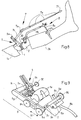
- Fig. 1a shows a base plate 3, which holes 3b, 3c, 3d has for receiving bone screws 4.
- Die Base plate 3 as shown in the bottom view according to FIG. 1b, three spaced apart Contact surfaces 3a, which lie on the femur 1 come so that the three-point support thus formed Tilt-free resting on the femur 1 guaranteed.
- the base plate 3 also has an opening 3f for receiving a bayonet lock and two alignment holes 3e, 3g.
- the bore 3b, as in Fig. 1a illustrated a countersink.
- the base plate 3 is, as shown in Fig. 3, in the Proximity of the condyles 1a in this way on the femur 1 arranged that the formed by the holes 3g, 3e Axis preferably in the direction of the loading axis 19b of the Femur 1 runs.
- a drilling jig two Steinmann nails roughly in the direction of the Load axis 19b set in the femur 1 and then the Base plate 3 placed on the femur 1 so that each a Steinmann nail runs through the holes 3g, 3e.
- a drilling jig is placed on the holes 3b, 3c, 3d the base plate 3, then holes in the femur 1 drilled and then inserted bone screws 4, so that the base plate 3, in its longitudinal orientation extending approximately in the direction of the load axis 19b, through the bone screws 4 with the femur 1 connected is.
- the device according to the invention has in one preferred embodiment, a reference device 5 which can be firmly connected to the base plate 3, the mutual position of base plate 3 and Reference device 5 is adjustable to the course of the Resection lines on the femur and tibia as exact as possible adjust.
- Figures 2a to 2c show such a Reference device 5, which has sub-elements, whose alignment defines a coordinate system X, Y, Z, with which coordinate system all others Manipulations and cuts on the femur 1 and tibia 2 be made.
- the reference device 5 comprises a base part 5a which is a locking part 5c of a bayonet lock is arranged with axis of rotation 5b and actuating lever 5d.
- the base part 5a is thus made with the base plate 3 connected that the lever 5d in the position shown is brought, then the closure member 5c in the Opening 3f is inserted, and then the snap-in part 5g is inserted into the countersink of the hole 3b ..
- the operating lever 5d in the direction 5e moved so that the formed by the parts 5c, 3f Bayonet lock snaps into place and the base part 5a firmly but is detachably connected to the base plate 3.
- a reference body 5o has longitudinal bores 5q with screws 5r fixed to the swivel plate 5h connectable.
- the longitudinal hole 5q also as an elongated hole is wider than the shaft of the screw 5r designed.
- the Reference body 5o due to the linear expansion of the Longitudinal bores 5q in the direction of movement 5s either can be moved in parallel or also around the axis of rotation 5t slidable in the direction of movement 5u. So the Reference body 5o with respect to the pivot plate 5h slidable, and especially slightly offset, and firmly connect with the screws 5r.
- Reference body 5o defined via the reference surfaces 5p as well as those firmly connected to the reference body 5o Forks 5m the alignment of the coordinate system X, Y, Z, which forms the reference coordinate system. in the As can be seen from FIG. 2c, reference body 5o is a Guide opening 5z arranged which one in the X direction longitudinal guide for a rack 10a formed.
- the reference body 5o has one in its Internally arranged worm gear 5w, which two includes vertical axes of rotation 5y, wherein at the an axis of rotation 5y a thumbscrew 5v as well as within of the reference body 50, a worm is arranged, and on the other axis of rotation 5y a gear 5w and an in the longitudinal guide 5z protruding gear 5x, which for Engagement in the rack 10a is determined.
- the gear 5x could also be directly on a 5y axis Knurled screw 5v to be attached, so that a Worm gear 5w could be dispensed with.
- 3 shows a femur 1, on which the base plate 3 is screwed on.
- the reference device 5 is with the Base plate 3 connected and can by pressing the Operating lever 5d released and removed at any time be reattached. 3 is also in the X direction longitudinal guide 5z visible.
- the Reference device 5 can also be configured such that this in addition to the pivot axis 5i in a Swivel axis 5i perpendicular second Pivot axis 5j with respect to the base part 5a in Direction of movement 5f is pivotally mounted, the Swivel angle can be fixed by screws and is fixable.
- the reference device 5 could also without the pivot axis 5i, only one Have pivot axis 5j.
- Fig. 4 symbolically shows the reference body 5o, in the Longitudinal guide 5z an insertion and holding part 6a one Control gauge 6 is inserted.
- the control gauge 6 comprises a holder 6b with a transparent attached to it Body 6d with grid lines 6e.
- the control gauge 6 serves for aligning the swivel plate 5h in the swivel direction 5k.
- the plug-in part is in the arrangement according to FIG. 3 6a inserted in the longitudinal guide 5z and then the in Direction of the holding part 6a or in the X direction slidably mounted transparent body 6d moved with holder 6b so that the transparent Body 6d, as indicated in Fig. 4, immediately in front of the Femoral condyle 1a comes to rest.
- the Grid lines 6e run with respect to that through the Reference body 5o predetermined coordinate system in Y and Z-direction.
- the transparent body 6d By turning the screws 51 accordingly can the transparent body 6d about the pivot axis 5i can be rotated.
- the location of the transparent body 6d by moving the Reference body 5o in the direction 5s or in the direction 5u can be set.
- the location of the Reference body 5o or the coordinate system in the Y and Z directions with respect to the position of the condyles 1a can be set very precisely.
- the anatomical axis 19a of the femur 1 is 19b relative to this loading axis inclined.
- the course of tibia 2 defines one mechanical axis 19d. Point in the position shown the femur 1 and the tibia 2 have a flexion of 0 ° on and the load axis 19b and the mechanical axis 19d are congruent.
- Fig. 5 shows an alignment rod 7, which the Reference body 5o with respect to the position of the femoral head 19c allowed to align.
- the alignment rod 7 includes one Mounting block 7a, which is by means of a knurled screw 7b can be attached to the fork 5m.
- a telescopic rod 7e with end pointer 7f is over the joint 7d with axis of rotation 7g and the bracket 7c with axis of rotation 7h on the mounting block 7a stored.
- the alignment rod 7 is designed and arranged on the reference device 5 that the Telescopic rod 7e essentially or as precisely as possible in the X direction runs, and pivotally mounted in the XY plane is.
- the position of the reference body 5o is also solved Screws 5r adjusted so that by palpation, for example with the so-called "two-finger method", the center of the femoral head 19c is felt, and then the end pointer 7f of the telescopic rod 7e on the thigh 1c is placed at this point, creating the reference body 5o is aligned such that the projection of the X axis (in the sagittal direction) through the center of the Hip head 19c runs. It can also help the course of the X axis of the grid lines 6e be set so that the X axis passes through the center of the Condyle 1a runs. Thus the X axis runs from one 15, congruent to Load axis 19b.
- the screws 5r are tightened and thereby the position of the reference body 5o with respect to the Swivel plate fixed 5h.
- the reference system or orthogonal axes defined in the X, Y and Z directions established.
- the reference device 5 has the Advantage on that all settings made on the Reference device 5 were made and thus quasi are stored on this. Therefore, it is possible reference device 5 set in this way via the To release bayonet lock 5b from the base plate 3 and to remove at the femur 1 or tibia 2 more To carry out manipulations. At a later time can the reference device 5 back on the base plate 3 are attached, the axes in the X, Y and Z directions run as previously defined and therefore no longer need to be set.
- the reference device 5 can be seen in that the course of the axes X, Y and Z with respect to the Position of the femur 1 and the condyles 1a very precisely let set.
- the reference device 5 could also be so simple that an adjustment of the reference body 5o with respect to the base plate 3 only in one or two dimensions is possible.
- base plate 3 and Reference device 5 can be in a another, simpler embodiment on the base plate 3 are omitted, in which the base part 5a Reference device 5 is screwed directly onto the femur 1.
- a tibia splint 8 is used to align the tibia 2 provided, which is shown in Figures 6 and 7.
- the tibia splint 8 is preferably on the tibia 2 in this way attached that the tibial splint 8, in a sagittal 15, congruent to the mechanical Axis 19d of the tibia 2 runs.
- a tibia plate 8a having two bores 8b with two Bone screws 8c anchored to the tibia 2.
- On Support part 8d is via a lockable ball joint 8x and the connecting part 8y with the tibia plate 8a connected.
- the ball joint 8x is within the 8x designated body arranged.
- a tibia rod 8k opens via a stop part 8i and a stop 8e into one End section 8h.
- the tibia rod 8k is in the released state displaceable in the direction of displacement 8f, with the Support web 8d a screw 8g is connected, which in tightened the tibia rod 8k firmly with the body 8x fixed, whereby the position of the tibia rod 8k in Movement direction 8f is fixed.
- On the knee joint far end is a support part 8s with support 8t on Lower leg 2a created and with this, for example fixed with the help of bandages.
- a sliding part 8u is with respect to the support part 8s in the direction of displacement 8w slidable and fixable with a screw 8v.
- the Tibial rod 8k opens into a sliding rod 81, which with respect to the longitudinal direction 8n of the tibia rod 8k slidably supported and with the help of a knurled screw 8m can be fixed with the tibia rod 8k.
- On the sliding part 8u is a rod-shaped holder 8o-projecting, which in a guide part 8p of the displacement rod 81 insertable, adjustable in the 8r direction, and with a knurled screw 8q can be fixed.
- the described Adjustment possibilities of the tibia rod 8k with respect to the Tibial plate 8a and the support part 8s allow this Adjust the course so that the tibia rod 8k in sagittal direction congruent with the anatomical axis 19d of the tibia 2 runs.
- Clamping instrument 20 of which an embodiment in FR 2 648 699, between the femur 1 and the tibia 2 introduced.
- the tensioning instrument 20 is based on the principle of a Spreading pliers and serves the articular surfaces of the tibia 2 and the femur 1 individually on the medial or lateral condyle apart so that the desired orientation arises between femur 1 and tibia 2.
- the tibia rod 8k the course of the mechanical axis 19d the tibia 2 can now indicate the tibia 2 by a corresponding adjustment of the tensioning device 20 in this way that the 8k tibial rod is sagittal is congruent with the alignment rod 7.
- the Leg axis also slightly angled in the varus-valgus direction be set to gradual. So there is Intends an angle between the possibility Introduce loading axis 19b and the tibia axis 19d.
- the Fastening bracket 9 comprises a tibia splint holder 9a the end portion 8h of the knurled screw 9b Tibial rod 8k can be firmly clamped.
- the mounting bracket 9 further includes a bracket base part 9g and a Bracket adjustment part 9c, which with respect to the bracket base 9g adjustable in the longitudinal direction 9f and with a Knurled screw 9h is fixable.
- the tibia splint holder 9a can be pushed in the sliding direction 9e with the Bracket adjustment part 9c connected and with the knurled screw 9d fixable.
- the temple base part 9g is fixed with a Crossbar part 9i connected, which a recess 9k for Has support on the reference body 5o.
- the Bracket cross part 9i is fixed with a knurled screw 91 the reference body 5o connectable.
- the majority Adjustment options of the mounting bracket 9 allow it the end section 8h of the tibia rod 8k in the predetermined Position to be firmly connected to the reference body 5o.
- the femur 1 and the tibia 2 are in one precisely defined location mutually fixed.
- the loading axis 19b is preferably aligned and the tibial axis 19d mutually, and their spanned angle is 90 degrees.
- the mounting bracket 9 can also be designed rectangular, in which the Tibial splint holder 9a and the crosspiece 9i on both sides with a temple base part 9g and one Bracket adjustment part 9c are connected.
- Such a rectangular mounting bracket 9 faces one Embodiment according to FIG. 9 has increased stability.
- the mounting bracket 9 has the advantage that the femur 1 and the tibia 2 in one defined aligned location are fixed, and that due to the U-shaped design of the mounting bracket 9 access to the operating field is not obstructed.
- FIG. 10 shows the arrangement according to FIG. 9, wherein additionally on the reference device 5 Moving device 10 is arranged, which one Base bar 10g and attached adapter parts 10h in Moving X and Y direction allowed.
- the Moving device 10 also as an adjusting device or to designate a feed device comprises one feed device 10e, which with a rack 10a is firmly connected.
- This rack 10a is partially in the longitudinal guide 5z arranged extending, the Gear 5x of the knurled screw 5v in the rack 10a engages around the rack 10a in the direction of displacement 10b, which corresponds to the X direction.
- the Feed device 10e has, analogously to that in the figures 2a to 2c shown reference device 5, a Knurled screw 10f, which is an invisible one Worm gear that drives one in one Gear arranged in a longitudinal guide through the Longitudinal guide guided rack 10c engages around this to move in the direction of displacement 10d.
- the 10 is the embodiment Direction of displacement 10d identical to the Y direction.
- the two axes of movement or displacement directions 10b, 10d preferably run at right angles to each other, can but also at a different angle to each other run.
- the reference device 5 could be the adjusting device 10 also be arranged on the mounting bracket 9, in which the Mounting bracket 9 a longitudinal guide 5z and a Knurled screw 5v for picking up and moving the rack 10a.
- Adjusting device 10 fastens a cutting jig 11, which slits running at different angles 11a has around the saw blade 12 with saw teeth 12a exactly at the angles predetermined by the implant to lead. 12 shows one with the saw blade 12 performed resection incision on the tibia front 2b. ever according to the embodiment of a knee joint prosthesis the angles of the resection cuts differ run. Therefore there are different cutting gauges 11 available, the appropriate cutting gauge 11 am Base beam 10g is attached.
- the cutting jig 11 has also bores 11b for guiding a drill for the Patella canal.
- the cutting jig 11 can by manual Turn the knurled screws 5v, 10f to the required Be driven.
- the cutting jig 11 move exactly parallel so that exactly parallel running resection surfaces on femur 1 and tibia 2 can be created.
- the racks 10a, 10c could be one Have scale, for example one on the surface engraved scale over which the traversed path is readable. This is especially true with a manual Procedure or a manual actuation of the Knurled screws 5v, 10f are an advantage.
- the possibility of one manual procedure has the advantage that the Device even if a computer or one fails Motor can still be operated, so that even in one such emergency situation a continuation of the operation is guaranteed.
- the knurled screws 5v, 10f are motor-driven.
- 14 schematically shows a drive device 17 according to the invention, which is connected to a computer 16 via a bidirectional data line 16c and is controlled by the latter.
- the drive device 17 comprises an electric motor 17d with a shaft 17c.
- An angle disk 17e and a sensor 17f for detecting the angle of rotation are arranged on this shaft 17c.
- the electric motor 17d is controlled by the computer 16 and the angle of rotation of the electric motor 17d is monitored by the computer 16 via the sensor signal 17f.
- the knurled screw 5v, 10f and the shaft 17c are connected to one another via a flexible shaft 17a, which has an adapter part 17b at both ends.
- the flexible shaft 17a is preferably made of a metal wire.
- the arrangement according to FIG. 14 has the following advantages: Bone surgery places the highest demands on sterility. Therefore, all objects that are close to the operating field must have sterile properties. It would take considerable effort to build a sterilizable electric motor, which could be arranged directly on the travel device 10.
- the use of a metal wire, for example spring steel wire has the advantage that the electric motor can be arranged, for example, one to two meters away from the operating field.
- the use of a spring steel wire string has the advantage of a high modulus of elasticity and a low hysteresis effect. Due to the greater distance from the operating field, there are fewer requirements with regard to the sterility of the drive device 17.
- the shaft 17a according to the invention also has the advantage that it can be sterilized and, since it is inexpensive to produce, can also be designed as a disposable product.
- the drive device 17 also has the advantage that the knurled screw 5v is both drivable and its angle of rotation can be monitored via the sensor 17f.
- the drive device 17 can also have a plurality of independent drives for flexible shafts 17a.
- the shaft 17a can be designed as a solid wire or as a hollow wire. Steel wires are preferably used, wires of other metals or of plastic or composite material also being suitable.
- the drive device 17 with an electric motor 17d, angle disk 17e and sensor 17f could be arranged in or in place of the knurled screw 5v, the drive device 17 being connected to a computer 16 via an electrical control and data line 16c.
- the Moving device 10 with a 14 driven in which the knurled screws 15v, 10f each with a shaft 17a are connected. It is not only possible with that Base bar 10g with attached adapter part 10h in X and Y direction, but also the Geometry of the condyle 1a at selected points as well to measure the tibia plateau.
- Base bar 10g with attached adapter part 10h in X and Y direction, but also the Geometry of the condyle 1a at selected points as well to measure the tibia plateau.
- the embodiment 10 is a guide 10k on the adapter part 10h a probe 101 with measuring tip 10n arranged.
- the Guide 10k is displaceable in the direction of 10m Adapter part stored for 10 hours.
- the geometry of a femoral condyle 1a can be measured, for example, as follows:
- the base bar 10g is initially moved without an adapter part 10h attached to it such that the base bar 10g comes into abutment with the femoral condyle 1a at the front of the femur 1.
- the position of the front of the femur 1 can thus be determined and stored by the computer 16.
- the base bar 10g is then moved away again and, as shown in FIG. 10, the adapter part 10h with probe 101 is arranged on the base bar 10g.
- the base bar 10g is then moved until the stylus tip 10n of the probe 101 reaches the illustrated support with the femur 1.
- the base bar 10g is moved away again, and a further measuring probe 101 is arranged for the guide 10k for the probe, which probe can be fastened with a knurled screw 10p.
- the measuring probe 101 is arranged eccentrically, the dorsal extent 1d of the condyle 1a can be measured by moving the base bar 10g.
- the probe 101 is arranged centrally, the depth of the pit 10b can be measured by moving the base bar 10g.
- the condyle can also be measured at several points by designing the probe accordingly.
- a scale extending in the longitudinal direction on the adapter part 10h is arranged , which allows the lateral position of the probe tip to be read, so that the total width of the femoral joint head can be determined on the basis of the measured, medial and lateral extension of the condyles 1a.
- This width can be entered into the computer by hand, for example, so that the computer has the geometric data of the femoral head available for further calculations.
- the measuring probes 101 can be used in many different ways be shaped to take into account the anatomical shape of the femur's surfacefaststasten.
- a probe 101 could also be like this be configured such that, similar to that in FIG. 11 shown, arranged on the guide 10k the dorsal Scanning area of the femur 1 allowed.
- the overall system for implanting a Total knee joint prosthesis included in a preferred Embodiment a computer or a computer with a screen.
- the coordinates of the location of the with the Measuring probes 101 determined measuring points of the condyles of the Femurs are the computer via the drive device 17 transmitted, the computer both the division of the Angle gear 17e as well as the gear ratio of Gear of the feed unit 10e is predetermined, so that the calculator the distances of the individual measuring points in absolute coordinates and preferably in the unit Can calculate millimeters.
- the computer Database with the geometric data available Knee joint implants saved using the calculator compares this data with the measured data and a proposes optimally fitting knee joint implant and this on the screen.
- Embodiment is shown on the screen as in Fig. 13a shown, the measured femur, the resection lines and the knee joint implant to be attached to the femur shown.
- the surgeon checks the presented Proposal and either confirms that proposal, shifts the resection lines in their entirety, or choose another one that seems more suitable to him Knee joint implant. After choosing the appropriate one
- the computer accesses a knee joint implant Database in which all geometric data of the Implant, especially the arrangement and the Course of the standard contact surfaces of the implant or the corresponding resection lines are stored. Based on this data, the computer determines which one a plurality of available cutting gauges 11 on the base bar 11g is to be attached to the previously determined cuts to do.
- a single cutting jig could 11 are provided, which are the angles of the respective Resection cut lines determined.
- their Cut line course on corresponding implants the resection lines on the femur according to the design and size of a each implant can be cut.
- the cutting jig 11 becomes the traversing device 10 controlled by the computer so that the cutting template 11 is moved into the first cutting position.
- the surgeon can Saw blade 12 in the respective slot 11a of the gauge 11 insert and make the cut.
- the device according to the invention it also enables a less experienced person Surgeons the femur 1 and the tibia 2 easily, exactly to cut and insert the implant.
- Figures 13a, 13b, 13c disclose an overall system for Inserting a knee prosthesis that does not have a cutting jig 11 Requires more because the location of the sawing device 14 and thus the position of the saw blade 12 directly from the Moving device 10 is controlled and determined.
- a rotary adjustment device 13q which is designed as a latching device 13a, is arranged on the base bar 10g of the displacement device 10.
- This latching device 13a has latching points 13n arranged distributed over its circumference, each latching point 13n defining a fixedly predetermined pivoting angle of the arm 13c in the pivoting direction 13m.
- a knurled screw 13b allows the screw shaft 13o to be raised or lowered.
- the rotary adjustment device 13q could also have a motor drive instead of the latching device 13a, which allows a predeterminable angle of rotation to be set.
- Such a motor-driven rotary adjustment device 13q preferably also comprises a rotation angle sensor which detects the angle of rotation, so that the angle to be taken up of the rotary adjustment device 13q can be specified, for example, with the aid of a control device or a computer.
- the arm 13c is connected to a second arm 13f via a joint which is movable in the direction of movement 13d and which is in turn connected to the third arm 13h via a joint which is movable in the direction of movement 13g.
- the third arm 13h forms an axial attachment 13i for the sawing device 14 on the one hand and a guide 13k with a slot 131 for the saw blade 12 on the other hand to pivot.
- the saw blade 12 forms a saw blade level and is slidably mounted in this plane.
- the arm 13 can be designed in such a way that it has a spring force, so that an increasing restoring force on the sawing device 14 is brought about when the saw blade 12 is fed to the condyle 1a.
- torsion springs could be arranged in the joints of the arm 13, for example.
- the guide 13k is firmly connected to the arm 13h.
- the guide 13k could also be articulated on the arm 13h via a joint, so that the guide 13k is pivotally mounted for fastening 13i. This measure allows the saw blade 12 to penetrate deeper into the body to be cut.
- the sawing device 14 has a handle 14a, which, in order to decrease too much by the Operation of caused moments with regard to the holding arm 13 is pivotable in the direction 14g about the axis 14h.
- the Handle 14a could also about an axis of rotation 13p be pivoted.
- the handle 14a thus serves the movement initiation in direction 14c and in Swivel direction 14d about the axis 13p. This is the location of the handle 14a in the vertical pivoting direction regardless of the position of the saw blade 12.
- the Inclination of the holding arm 13 with respect to the base bar 10g is, as shown in Fig. 13c, by rotating the arm 13c possible about the axis of rotation 13e of the latching device.
- the position of the saw blade 12 by the Computer 16 controlled moving device 10 determines.
- the guide 13k is preferably designed with a slot 131 around the relatively thin saw blade 12 to lead in a defined position, and to a Avoid bending the saw blade 12.
- the Holding arm 13 together with the saw device 14 relative large forces on the moving device 10 or Base plate 3 could impact is in the with Fig. 13a embodiment shown a frame 15th provided that a cable winding device 14f includes and a rope 14e, which has the task of a at least the gravity of the sawing device 14 to generate compensating counterforce F.
- the frame 15 includes a boom 15a, a vertical rod 15b Assumed 15c and wheels 15d.
- the frame 15 On the frame 15 is also the supply and discharge line 14b for driving the sawing device 14 arranged.
- the computer 16 with a screen 16a and keyboard 16b attached to the frame 15.
- the drive device 17 attached to the frame 15, wherein the two knurled screws 5v, 10f over the flexible shaft 17a are driven by the drive device 17.
- the holding arm 13 shown could also be such be configured such that it has sensors which the angles in the direction of movement 13d, 13g and 13m too Allow to grasp the exact position of the saw blade 12 to grasp or in place of a saw blade 12 arranged probe the position and geometry of the condyle 1a measure.
- FIGS 16a to 16d disclose another Embodiment of an anchorable on the femur 1 Base plate 3 or a base device 3.
- This Base device 3 includes a base platform 3h Longitudinal axis 3s, on which four can be displaced in the direction 31 supported legs 3i, 3k are arranged. The legs 3i, 3k are displaceable on grooves 3o running in the direction 31 stored.
- a shaft 3n with an external thread engages Internal thread of the legs 3i, 3k.
- the shaft 3n has one 3p screw head accessible from the side.
- the thread in Leg 3i is a left-hand thread, the thread in leg 3k is Right-hand thread designed, the thread of the shaft 3n is adapted accordingly to the intervention.
- the shaft 3n has one in the middle cylindrical, the diameter of the shaft 3n exceeding section 3m, which in one Gap 3r of the base platform 3h is arranged, and which in the direction of displacement 31 on both sides with little Game rests on the base platform 3h and thereby the Position of the shaft 3n with respect to the base platform 3h in Direction 31 defines and therefore as a centering element 3m serves.
- 16b shows two in a side view opposite legs 3i, 3k, which on the opposite inner surfaces in the direction of displacement 31 have protruding tips 3q, which for penetration into the femur 1 are determined.
- the base device 3 is attached to the femur 1 in such a way that this is initially in the direction of the femur axis 19a is placed on the femur 1 and then the opposite legs 3i, 3k by rotating the shaft 3n be brought closer together until the peaks 3q in the Femur 1 penetrate and the base device 3 with safely the femur 1 is connected.
- the shaft 3n is configured on both sides Screw head 3p on, so that the shaft 3n optionally from one of the two legs 3i, 3k can be actuated.
- Base device 3 can be seen in that after the Attach to the femur 1 in the direction of the femur axis 19a or in the direction of the intramedular cavity of the femur 1.
- the base device 3 thus has an intramedular course, but without one to use intramedially arranged body.
- the two recesses 3b, 3f are similar to that in FIG Base plate 3 designed according to FIG. 1a and are used for Attach the reference body 5 by means of a Bayonet catch.
- 16c shows a top view of the Arrangement of the recesses 3b, 3f on the base platform 3h.
- the two lower recesses 3b, 3f define one Straight 19b, which is through the center of the base platform 3h straight line 19a, 3s at an angle ⁇ cuts. This angle ⁇ is preferably in the range of 6 ⁇ 2 degrees.
- the straight line 19a corresponds to the Femur 1 attached base device 3 the course of the Anatomical axis 19a of the femur 1.
- the Base device 3 has two pairs of recesses 3b, 3f on, the one arranged above the straight line 19a, 3s Pair, as shown in Fig. 16d, at the femur 1 one right leg is used, whereas the lower pair is to be used for femur 1 of a left leg in order to predetermined anatomical axis 19a of the femur 1 den Approximately specify the course of the load axis 19b.
Landscapes
- Health & Medical Sciences (AREA)
- Surgery (AREA)
- Life Sciences & Earth Sciences (AREA)
- Biomedical Technology (AREA)
- Medical Informatics (AREA)
- Oral & Maxillofacial Surgery (AREA)
- Nuclear Medicine, Radiotherapy & Molecular Imaging (AREA)
- Transplantation (AREA)
- Physical Education & Sports Medicine (AREA)
- Engineering & Computer Science (AREA)
- Orthopedic Medicine & Surgery (AREA)
- Heart & Thoracic Surgery (AREA)
- Dentistry (AREA)
- Molecular Biology (AREA)
- Animal Behavior & Ethology (AREA)
- General Health & Medical Sciences (AREA)
- Public Health (AREA)
- Veterinary Medicine (AREA)
- Prostheses (AREA)
- Surgical Instruments (AREA)
Abstract
Description
Die vorliegende Erfindung betrifft eine Vorrichtung, welche es einem Chirurgen erlaubt, bei der Implantation einer Kniegelenktotalendoprothese die Resektion des Femurs und der Tibia in äusserst präziser Weise durchzuführen.The present invention relates to a device which allows a surgeon to Implantation of a total knee joint endoprosthesis Resection of the femur and tibia in an extremely precise manner Way to perform.
Die exakte Lage der Resektionslinien an Femur und Tibia sind für eine lange Lebensdauer einer Kniegelenktotalendoprothese von entscheidender Bedeutung. Bislang ist die Durchführung der Resektion selbst für einen erfahrenen Chirurgen äusserst anspruchsvoll, gilt es doch durch die Operation die Normanlageflächen entsprechend der Vorgabe der Geometrie der Endoprothese zu schaffen, dabei die Normanlageflächen entsprechend der gewünschten mechanischen Beinachsen auszurichten wobei gegebenenfalls auch pathologische Fehlstellungen zu korrigieren sind, und zudem die Lage und die Wirkung der vorhandenen Bänder und Muskeln zu berücksichtigen. Die Ausrichtung von Tibia und Femur erfolgt üblicherweise durch Inaugenscheinnahme unter allfälliger Zuhilfenahme von intra- oder extramedullären Hilfsmitteln, wobei als zusätzliche Behinderung das Operationsfeld oft einen erschwerten Zugang aufweist. Diese Randbedingungen können selbst bei Chirurgen mit grosser Erfahrung Stressituationen verursachen.The exact location of the resection lines on the femur and tibia are one for a long life Total knee joint endoprosthesis vital. So far, the resection itself is for an experienced surgeon is extremely demanding but through the operation the Norman contact surfaces according to the specification of the geometry of the endoprosthesis create the standard contact surfaces according to the to align the desired mechanical leg axes possibly also pathological malpositions correct, and also the location and impact of to consider existing ligaments and muscles. The Alignment of the tibia and femur is usually done by inspection with any help of intra- or extramedullary devices, whereby as additional disability often an operation field difficult access. These boundary conditions can even with surgeons with great experience Cause stressful situations.
Eine Kniegelenktotalendoprothese besteht aus einer am Femur und einer an der Tibia befestigten Komponente. Bevor die Eniegelenktotalendoprothese implantiert werden kann müssen die angrenzenden Knochenbereiche des Femurs und der Tibia in geeigneter Weise reseziert werden, um Normanlageflächen entsprechend der Geometrie der Endoprothesen zu schaffen. Üblicherweise werden die Frontalen der Tibia und des Femurs reseziert. Wenigstens der Femur erhält darüber hinaus zumindest einen sogenannten Dorsal- sowie einen Ventralschnitt, da der Femurteil von Totalendoprothesen üblicherweise u-förmig ausgestaltet ist. Die im allgemeinen von Herstellern von Knieprothesen angebotenen Instrumente erlauben nicht die erforderlichen Knochenschnitte am Femur und an der Tibia mit der erforderlichen Genauigkeit vorzunehmen.A total knee joint endoprosthesis consists of an am Femur and a component attached to the tibia. Before the total joint arthroplasty can be implanted the adjacent bone areas of the femur and the Tibia to be resected appropriately Norman contact surfaces according to the geometry of the To create endoprostheses. Usually the Frontals of the tibia and femur resected. At least the femur also receives at least one so-called dorsal and a ventral incision, because the Femoral part of total endoprostheses usually U-shaped is designed. The generally from manufacturers of Instruments offered to knee prostheses do not allow the required bone cuts on the femur and on the tibia with the required accuracy.
Als weitere wesentliche Forderung gilt es jedoch zu berücksichtigen, dass die bei der Biegung und Streckung des Knies aneinander gleitenden Komponenten der Knieprothese immer die richtige Stellung zueinander haben, d.h. dass die mechanische Beinachse maximal 3° Varus oder 3° Valgus von der physiologischen Beinachse abweichen darf, bevorzugt beträgt die Abweichung weniger als ± 2°. Zudem gilt es zu berücksichtigen, dass die flexible Verbindung zwischen den beiden Komponenten durch Bänder und Muskeln bewirkt wird, soweit diese bei der Implantation der Prothese erhalten bleiben. Dies erfordert eine Equilibrierung des Bandapparates, welche sowohl bei der Extension als auch bei der Flexion eine gute Stabilität des Kniegelenks bewirkt.However, it is a further essential requirement take into account that when bending and stretching components of the knee sliding together Prosthetic knee always in the correct position to each other, i.e. that the mechanical leg axis is a maximum of 3 ° Varus or 3 ° valgus deviate from the physiological leg axis allowed, preferably the deviation is less than ± 2 °. It is also important to take into account that the flexible Connection between the two components by straps and muscles is caused, insofar as this occurs in the The implantation of the prosthesis remains intact. This requires an equilibration of the ligament apparatus, which both a good extension and flexion Stability of the knee causes.
Die bekannten Instrumentarien für die Implantation von Kniegelenktotalendoprothesen umfassen in der Regel folgende Kittel:
- Mittel zur Ausrichtung der Tibia bezüglich dem Femur zur Erzielung der gewünschten Beinachsenstellung;
- Mittel zur Herstellung der gewünschten Spannung der Kniebänder;
- Mittel zur Durchführung der Resektion von Tibia und Femur, in Form von Schneidlehren, welche der Führung eines Sägeblattes dienen.
- Means for aligning the tibia with respect to the femur to achieve the desired leg axis position;
- Means for establishing the desired tension of the knee ligaments;
- Means for performing the resection of the tibia and femur, in the form of cutting gauges, which serve to guide a saw blade.
Ein derartiges Instrumentarium ist aus der Druckschrift EP 0 322 363 A1 bekannt. Dieses Instrumentarium verwendet ein extramedulläres Mittel zum Ausrichten von Tibia und Femur (extramedullary alignment system) und weist den Nachteil auf, dass die Ausrichtung des Femurs nur mit Hilfe eines Röntgenapparates bestimmbar ist. Zudem erfolgt die Befestigung des Bezugssystems für die Knochenschnitte nach Augenmass, wobei das Bezugssystem zudem den Zugang zum Operationsfeld erschwert.Such an instrument is from EP 0 322 363 A1 known. This set of instruments uses a Extra medullary means for aligning the tibia and femur (extramedullary alignment system) and has the disadvantage that the alignment of the femur only with the help of a X-ray apparatus can be determined. In addition, the Attachment of the reference system for the bone cuts after A sense of proportion, with the reference system also providing access to Operating field difficult.
Ein weiteres Instrumentarium ist aus der Druckschrift EP 0 691 110 A2 bekannt. Dieses Instrumentarium verwendet ein intramedulläres Mittel zum Ausrichten von Tibia und Femur (intramedullary alignment system) und weist den Nachteil auf, dass zur gegenseitigen Fixation von Tibia und Femur je ein Führungsspiess erforderlich ist, welcher in den Tibia- bzw. Femurmarkraum eingeführt wird. Dieser Eingriff in den Markraum kann Thrombosen bzw. Embolien verursachen, was sich letal auswirken kann.Another set of instruments is from EP 0 691 110 A2 known. This set of instruments uses a intramedullary means to align the tibia and femur (intramedullary alignment system) and has the disadvantage on that for mutual fixation of the tibia and femur A guide spike is required, which is in the Tibial or femoral marrow space is introduced. This intervention in the medullary can cause thrombosis or embolism, what can be lethal.
Eine Vorrichtung gemäß der Präambel von Anspruch 1 ist
aus der US-A-4 457 307 bekannt.An apparatus according to the preamble of
Es ist Aufgabe der vorliegenden Erfindung eine Vorrichtung zur Festlegung von Resektionsschnitten am Femur sowie an der Tibia zur Vorbereitung einer Implantation einer Kniegelenktotalendoprothese zu schaffen, welches einfach und zuverlässig reproduzierbar durchzuführen ist. The object of the present invention is a device to determine resection cuts on the femur and on the tibia to prepare a Implantation of a total knee joint endoprosthesis create which is easily and reliably reproducible is to be carried out.
Diese Aufgabe wird gelöst mit einer Vorrichtung aufweisend
die Merkmale von Anspruch 1. Die
Unteransprüche 2 bis 21 beziehen
sich auf weitere vorteilhafte Ausgestaltungen der
erfindungsgemässen Vorrichtung.This object is achieved with a device
the features of
Die erfindungsgemässe Vorrichtung umfasst in einer vorteilhaften Ausgestaltung eine Referenzvorrichtung bestehend im wesentlichen aus einem lösbar im distalen Bereich des Femurs arretierbaren Basisteil sowie einem gelenkig und/oder verschiebbar mit dem Basisteil verbundenen Referenzkörper, welcher ein Koordinatensystem X,Y,Z bestimmende Mittel aufweist, wobei die Ausrichtung des Referenzkörpers bezüglich dem Femur lagegenau positionierbar ist und wobei ein zwischen dem Referenzkörper und dem Basisteil wirkendes Betätigungsmittel zum Fixieren deren gegenseitiger Lage vorgesehen ist, und wobei die das Koordinatensystem X,Y,Z bestimmende Mittel zum ausgerichteten Befestigen von Bearbeitungsmitteln wie einer Schneidlehre, eines Basisbalkens oder einer Messvorrichtung ausgestaltet sind.The device according to the invention comprises in one advantageous embodiment, a reference device consisting essentially of a detachable in the distal Area of the femur lockable base part and a articulated and / or slidable with the base part connected reference body, which is a coordinate system X, Y, Z has determining means, the orientation of the reference body with respect to the femur is positionable and with a between the Acting reference body and the base part Actuating means for fixing their mutual position is provided, and wherein the coordinate system X, Y, Z determining means for the aligned fastening of Machining aids such as a cutting jig, one Base bar or a measuring device are configured.
Ein Vorteil dieser Vorrichtung ist darin zu sehen, dass die Referenzvorrichtung fest mit dem Femur verbunden und vorzugsweise in Verlaufsrichtung der Belastungsachse des Femurs ausgerichtet ist, und dass alle Schnitte an Femur und Tibia bezüglich diesem Referenzsystem ausgerichtet getätigt werden, so dass sehr präzis und definiert ausgerichtet verlaufende Resektionsschnitte bzw. Resektionsflächen an Femur und Tibia erstellbar sind.An advantage of this device can be seen in the fact that the reference device is firmly connected to the femur and preferably in the direction of the load axis of the Femur is aligned, and that all cuts to femur and tibia aligned with this reference system be done so that very precise and defined aligned resection cuts or Resection surfaces on the femur and tibia can be created.
Die Referenzvorrichtung ist mit einer Vielzahl von unterschiedlich ausgestalteten Mitteln am Femur befestigbar, so beispielsweise mit Knochenschrauben, oder den Femur zumindest teilweise umfassende Greifarme, welche zur besseren Verankerung zudem Dornen aufweisen können, welche in den Femur eindringen.The reference device comes with a variety of differently designed means on the femur attachable, for example with bone screws, or the femur at least partially comprehensive gripping arms, which can also have spines for better anchoring, which penetrate the femur.
Die erfindungsgemässe Vorrichtung umfasst in einer weiteren vorteilhaften Ausgestaltung eine extramedullär und lösbar im distalen Bereich des Femurs befestigbare Referenzvorrichtung, deren Ausrichtung bezüglich dem Femur lagegenau positionierbar ist, sowie eine extramedullär und lösbar an der Tibia befestigbare Tibiaschiene, wobei die Ausrichtung der Tibiaschiene bezüglich der Tibia lagegenau positionierbar ist, sowie eine die Referenzvorrichtung sowie die Tibiaschiene lösbar fest verbindende Befestigungsvorrichtung.The device according to the invention comprises in one Another advantageous embodiment is an extra medullary and releasably attachable in the distal area of the femur Reference device, its orientation with respect to the femur is positionable exactly, as well as an extramedullary and Tibial splint can be detachably attached to the tibia, the Alignment of the tibia splint with respect to the tibia is positionable, and a the reference device as well as releasably firmly connecting the tibia splint Fastening device.
Diese erfindungsgemässe Ausführungsform weist den Vorteil auf, dass die Tibia bezüglich dem Femur in eine genau definierte Lage gebracht und danach fixiert werden kann. Daher kann die Verlaufsrichtung der Resektionsschnitte an der Tibia über die am Femur befestigte Schneidvorrichtung vorgegeben werden. Die Stellung der Tibia kann bezüglich dem Femur genau eingestellt werden, um beispielsweise den Verlauf der mechanischen Beinachse zu korrigieren. In einer vorteilhaften Ausgestaltung ist die Befestigungsvorrichtung U-förmig oder rechteckförmig ausgestaltet, so dass der Operationsbereich am Knie auch bei angebrachter Befestigungsvorrichtung weitgehend frei zugänglich ist.This embodiment according to the invention has the advantage on that the tibia with respect to the femur in an exact defined position and can then be fixed. Therefore, the direction of the resection cuts can the tibia via the cutting device attached to the femur be specified. The position of the tibia can be related the femur can be adjusted precisely, e.g. Correct the course of the mechanical leg axis. In an advantageous embodiment is Fastening device U-shaped or rectangular designed so that the surgical area on the knee too largely free when the fastening device is attached is accessible.
Die erfindungsgemässe Vorrichtung umfasst in einer weiteren vorteilhaften Ausgestaltung eine lösbar am distalen Bereich des Femurs arretierbare Referenzvorrichtung, deren Ausrichtung bezüglich dem Femur lagegenau positionierbar ist, sowie eine mit der Referenzvorrichtung beweglich verbundene Schneidvorrichtung, insbesondere eine Schneidlehre zum Führen eines Sägeblattes oder eine Sägevorrichtung mit einem Sägeblatt, wobei die Ausrichtung der Schneidvorrichtung, insbesondere des Sägeblattes zumindest durch die Ausrichtung der Referenzvorrichtung bestimmt ist. Es lassen sich Schneidvorrichtungen mit unterschiedlichsten Schneidverfahren verwenden, zum Beispiel Sägen, Ultraschalltrennvorrichtungen oder auch die Verwendung von Laser. Die erfindungsgemässe Vorrichtung erlaubt die Schneidvorrichtung derart zu führen, dass der Schnitt in der vorgesehenen Richtung verläuft. Zum Erzeugen des Schnittes erweist sich als eine vorteilhafte Methode die Verwendung einer Säge.The device according to the invention comprises in one another advantageous embodiment, a detachable on Lockable distal area of the femur Reference device, its orientation with respect to the femur is positionable exactly, as well as one with the Reference device movably connected Cutting device, in particular a cutting gauge for Carrying a saw blade or a sawing device a saw blade, the orientation of the Cutting device, in particular of the saw blade at least determined by the orientation of the reference device is. Cutting devices can be used with use different cutting methods to Example saws, ultrasonic separators or the use of lasers. The inventive Device allows the cutting device in this way make the cut in the intended direction runs. To create the cut turns out to be one advantageous method of using a saw.
In einer besonders vorteilhaften Ausgestaltung umfasst die Sägevorrichtung ein Sägeblatt, dessen Verlauf eine Sägeblattebene definiert, wobei die Sägevorrichtung mit einem Verbindungsmittel an der Referenzvorrichtung bzw. an der Verstelleinrichtung befestigt ist, und wobei das Verbindungsmittel sowie die Sägevorrichtung derart ausgestaltet ist, dass das Sägeblatt ausschliesslich in der Sägeblattebene verschiebbar gelagert ist.In a particularly advantageous embodiment, the Sawing device a saw blade, the course of which a Saw blade level defined, the sawing device with a connecting means on the reference device or the adjusting device is attached, and wherein the Connection means and the sawing device in such a way is designed so that the saw blade is exclusively in the saw blade level is slidably mounted.
Diese Ausführungsform weist den Vorteil auf, dass die Ausrichtung des Sägeblattes fest vorgegeben ist, so dass sich der Operateur ausschliesslich auf das Bewegen des Sägeblattes zum Knochen hin und auf die Durchführung der Resektion konzentrieren kann, in der Gewissheit, dass die Ausrichtung der Resektionsebene stimmt. Dies Bedeutet für den Operateur eine erhebliche Erleichterung während der Resektion, kann er sich doch im Wesentlichen auf das Schneiden konzentrieren, wobei er sich auf eventuell vorhandene Hindernisse wie Bänder konzentrieren kann, ohne sich jedoch um die Verlaufsrichtung der Säge kummern zu müssen.This embodiment has the advantage that the Alignment of the saw blade is fixed so that the surgeon only focuses on moving the Saw blade towards the bone and on the implementation of the Resection can concentrate, knowing that the Alignment of the resection plane is correct. This means for the surgeon a significant relief during the Resection, he can essentially focus on that Focus on cutting, focusing on possibly can focus on existing obstacles such as tapes without care about the direction of the saw have to.
Die erfindungsgemässe Vorrichtung ist motorisch angetrieben. Zudem kann ein Rechner vorgesehen sein, welcher das Verfahren der Vorrichtung sowie das Schneiden überwacht oder sogar ansteuert.The device according to the invention is motorized driven. A computer can also be provided which is the process of the device as well as the cutting monitored or even controlled.
Resektionsschnitte an Femur oder Tibia werden insbesondere durchgeführt, indem eine Referenzvorrichtung am distalen Bereich des Femurs fixiert und anschliessend bezüglich der Verlaufsrichtung des Femurs ausgerichtet wird, und indem eine Schneidlehre zum Führen eines Sägeblattes oder eine Sägevorrichtung mit einem Sägeblatt mit der ausgerichteten Referenzvorrichtung verschiebbar verbunden und in einer die Verlaufsrichtung des Resektionsschnittes bestimmenden Ausrichtung geführt wird, und indem mit dem ausgerichtet geführten Sägeblatt die Resektion durchgeführt wird.Resection incisions on the femur or tibia are particularly important performed by using a reference device on the distal Area of the femur fixed and then with respect to the Direction of the femur is aligned, and by a cutting jig for guiding a saw blade or a Sawing device with a saw blade with the aligned Reference device slidably connected and in one determine the direction of the resection cut Alignment is done, and by aligning with that guided saw blade the resection is performed.
Nachfolgend wird die Erfindung anhand von Ausführungsbeispielen beschrieben. Es zeigen:
- Fig. 1a
- eine perspektivische Ansicht einer auf dem Femur befestigten Basisplatte;
- Fig. 1b
- eine Unteransicht einer Basisplatte;
- Fig. 2a
- eine Seitenansicht einer Referenzvorrichtung;
- Fig. 2b
- eine Draufsicht einer Referenzvorrichtung;
- Fig. 2c
- eine Rückansicht einer Referenzvorrichtung;
- Fig. 3
- eine perspektivische Ansicht einer auf dem Femur befestigten Referenzvorrichtung;
- Fig. 4
- eine perspektivische Ansicht einer an der Referenzvorrichtung befestigten Kontrollehre;
- Fig. 5
- eine perspektivische Ansicht eines mit der Referenzvorrichtung verbundenen Ausrichtstabes;
- Fig. 6,7
- eine perspektivische Ansicht einer Tibiaschiene;
- Fig. 8
- eine perspektivische Ansicht einer mit dem Ausrichtstab zu überprüfende Tibiaschiene;
- Fig. 9
- eine perspektivische Ansicht eines mit einem Befestigungsbügel bei 90° flektiert gehaltenen Gelenkes;
- Fig. 10
- eine an der Referenzvorrichtung befestigte Verfahreinrichtung;
- Fig. 11
- eine Ansicht einer Verfahreinrichtung mit einem Basisbalken und einem daran befestigten Messbalken;
- Fig. 12
- eine Ansicht einer am Basisbalken befestigten Schneidlehre;
- Fig. 13a
- eine perspektivische Ansicht eines Gesamtsystems zum Einsetzen einer Knieprothese;
- Fig. 13b
- eine Aufsicht auf eine Referenzvorrichtung sowie eine daran befestigte Schneidvorrichtung;
- Fig. 13c
- eine Detailansicht einer Einrastvorrichtung;
- Fig. 14
- eine schematische Ansicht einer mit einem Rechner angesteuerten Antriebsvorrichtung;
- Fig. 15
- eine sagittale Ansicht von Femur und Tibia sowie deren Achsverläufe;
- Fig. 16a - 16d
- ein weiteres Ausführungsbeispiel einer am Femur zu befestigenden Basisplatte.
- Fig. 1a
- a perspective view of a base plate attached to the femur;
- Fig. 1b
- a bottom view of a base plate;
- Fig. 2a
- a side view of a reference device;
- Fig. 2b
- a plan view of a reference device;
- Fig. 2c
- a rear view of a reference device;
- Fig. 3
- a perspective view of a reference device attached to the femur;
- Fig. 4
- a perspective view of a control gauge attached to the reference device;
- Fig. 5
- a perspective view of an alignment rod connected to the reference device;
- Fig. 6.7
- a perspective view of a tibia splint;
- Fig. 8
- a perspective view of a tibial splint to be checked with the alignment rod;
- Fig. 9
- a perspective view of a joint held with a mounting bracket flexed at 90 °;
- Fig. 10
- a moving device attached to the reference device;
- Fig. 11
- a view of a moving device with a base bar and a measuring bar attached thereto;
- Fig. 12
- a view of a cutting jig attached to the base bar;
- 13a
- a perspective view of an overall system for inserting a knee prosthesis;
- Fig. 13b
- a top view of a reference device and a cutting device attached thereto;
- 13c
- a detailed view of a locking device;
- Fig. 14
- a schematic view of a drive device controlled by a computer;
- Fig. 15
- a sagittal view of the femur and tibia and their axes;
- 16a-16d
- another embodiment of a base plate to be attached to the femur.
Nachfolgend sind die gleichen Teile mit denselben Bezugszeichen versehen.Below are the same parts with the same Provide reference numerals.
Ein wesentlicher Gedanke der erfindungsgemässen
Vorrichtung zum
Einsetzen einer Kniegelenktotalendoprothese ist die
Verwendung eines Bezugssystems, welches am Femur 1
verankerbar ist. Dieses Bezugssystem dient als Referenz
für alle Handhabungen und Verfahrensschritte, um die Tibia
2 bezüglich dem Femur 1 auszurichten und die Resektion an
den Gelenkflächen durchzuführen. Das am Femur 1 verankerte
Bezugssystem ist in einer vorteilhaften Ausgestaltung in
dessen Ausrichtung bezüglich dem Femur 1 verstellbar, um
das Bezugssystem insbesondere in Belastungsrichtung des
Femurs 1 verlaufend auszurichten.An essential idea of the inventive
Device for
The insertion of a total knee joint endoprosthesis is the
Use of a reference system, which on the
Fig. 1a zeigt eine Basisplatte 3, welche Bohrungen
3b,3c,3d aufweist zur Aufnahme von Knochenschrauben 4. Die
Basisplatte 3 weist, wie auf der Unteransicht gemäss Fig.
1b ersichtlich, drei beabstandet angeordnete
Auflageflächen 3a auf, welche auf dem Femur 1 zu liegen
kommen, so dass die dadurch gebildete Dreipunktauflage ein
verkippungsfreies Aufliegen auf dem Femur 1 gewährleistet.
Die Basisplatte 3 weist zudem eine Öffnung 3f zur Aufnahme
eines Bajonettverschlusses sowie zwei Ausrichtbohrungen
3e, 3g auf. Zudem weist die Bohrung 3b, wie in Fig. 1a
dargestellt, eine Ansenkung auf.Fig. 1a shows a
Die Basisplatte 3 wird, wie in Fig. 3 dargestellt, in der
Nähe der Kondylen 1a derart auf dem Femur 1 ausgerichtet
angeordnet, dass die durch die Bohrungen 3g,3e gebildete
Achse vorzugsweise in Richtung der Belastungsachse 19b des
Femurs 1 verläuft. Dazu werden mit einer Bohrlehre zwei
Steinmannnägel ungefähr in Verlaufsrichtung der
Belastungsachse 19b in den Femur 1 gesetzt und danach die
Basisplatte 3 derart auf den Femur 1 aufgelegt, dass je
ein Steinmannnagel durch die Bohrungen 3g,3e verläuft.
Daraufhin wird eine Bohrlehre auf die Bohrungen 3b,3c,3d
der Basisplatte 3 aufgesetzt, daraufhin Löcher im Femur 1
gebohrt und anschliessend Knochenschrauben 4 eingeführt,
so dass die Basisplatte 3, in ihrer Längsausrichtung
ungefähr in Richtung der Belastungsachse 19b verlaufend,
durch die Knochenschrauben 4 mit dem Femur 1 fest
verbunden ist.The
Die erfindungsgemässe Vorrichtung weist in einer
bevorzugten Ausführungsform eine Referenzvorrichtung 5
auf, welche fest mit der Basisplatte 3 verbindbar ist,
wobei die gegenseitige Lage von Basisplatte 3 und
Referenzvorrichtung 5 einstellbar ist, um den Verlauf der
Resektionslinien an Femur und Tibia möglichst exakt
einzustellen. Die Figuren 2a bis 2c zeigen eine derartige
Referenzvorrichtung 5, welches Teilelemente aufweist,
deren Ausrichtung ein Koordinatensystem X,Y,Z definieren,
bezüglich welchem Koordinatensystem alle weiteren
Manipulationen und Schnitte an Femur 1 und Tibia 2
vorgenommen werden.The device according to the invention has in one
preferred embodiment, a
Die Referenzvorrichtung 5 umfasst ein Basisteil 5a, an
welchem ein Verschlussteil 5c eines Bajonettverschlusses
mit Drehachse 5b und Betätigungshebel 5d angeordnet ist.
Das Basisteil 5a wird derart mit der Basisplatte 3
verbunden, dass der Hebel 5d in die dargestellte Position
gebracht wird, daraufhin das Verschlussteil 5c in die
Öffnung 3f eingeführt wird, und daraufhin das Einrastteil
5g in die Ansenkung der Bohrung 3b eingeführt wird..
Daraufhin wird der Betätigungshebel 5d in Richtung 5e
bewegt, so dass der durch die Teile 5c,3f gebildete
Bajonettverschluss einrastet und das Basisteil 5a fest
jedoch lösbar mit der Basisplatte 3 verbunden ist.The
Auf dem Basisteil 5a ist eine um die Schwenkachse 5i in
Richtung 5k schwenkbar gelagerte Schwenkplatte 5h
angeordnet, wobei die Schwenkplatte 5h zwei Bohrungen mit
Innengewinde zur Aufnahme je einer Inbusschraube 51
aufweist. Diese Schrauben 51 werden derart tief in das
Innengewinde gedreht, dass sie auf dem Basisteil 5a
aufliegen. Die relative Neigung zwischen dem Basisteil 5a
und der Schwenkplatte 5h lässt sich, wie am besten aus
Fig. 2c ersichtlich, durch die jeweilige Einschraubtiefe
der beiden gegenüberliegend angeordneten Inbusschrauben 51
einstellen.On the
Ein Referenzkörper 5o aufweisend Längsbohrungen 5q ist
mittels Schrauben 5r fest mit der Schwenkplatte 5h
verbindbar. Die Längsbohrung 5q, auch als Langloch
bezeichnet, ist breiter als der Schaft der Schraube 5r
ausgestaltet. Bei gelösten Schrauben 5r ist der
Referenzkörper 5o auf Grund der Längenausdehnung der
Längsbohrungen 5q in Bewegungsrichtung 5s entweder
parallel verschiebbar oder zudem auch um die Drehachse 5t
in Bewegungsrichtung 5u verschiebbar. Somit lässt sich der
Referenzkörper 5o bezüglich der Schwenkplatte 5h
verschiebbar, und insbesondere leicht versetzt anordnen,
und mit Hilfe der Schrauben 5r fest verbinden. Der
Referenzkörper 5o definiert über die Referenzflächen 5p
sowie die fest mit dem Referenzkörper 5o verbundenen
Gabeln 5m die Ausrichtung des Koordinatensystems X,Y,Z,
welches das Referenz-Koordinatensystem ausbildet. Im
Referenzkörper 5o ist, wie aus Fig. 2c ersichtlich, eine
Führungsöffnung 5z angeordnet, welche eine in X-Richtung
verlaufende Längsführung für eine Zahnstange 10a
ausbildet. Der Referenzkörper 5o weist ein in seinem
Inneren angeordnetes Schneckengetriebe 5w auf, welche zwei
senkrecht verlaufende Drehachsen 5y umfasst, wobei an der
einen Drehachse 5y eine Rändelschraube 5v sowie innerhalb
des Referenzkörpers 50 eine Schnecke angeordnet ist, und
an der anderen Drehachse 5y ein Getriebe 5w sowie ein in
die Längsführung 5z vorstehendes Zahnrad 5x, welches zum
Eingriff in die Zahnstange 10a bestimmt ist. Das Zahnrad
5x könnte auch direkt auf einer Achse 5y der
Rändelschraube 5v befestigt sein, so dass auch ein
Schneckengetriebe 5w verzichtet werden könnte.A reference body 5o has longitudinal bores 5q
with
Fig. 3 zeigt einen Femur 1, auf welchem die Basisplatte 3
angeschraubt ist. Die Referenzvorrichtung 5 ist mit der
Basisplatte 3 verbunden und kann durch ein Betätigen des
Betätigungshebels 5d jederzeit gelöst und entfernt oder
wieder befestigt werden. Aus Fig. 3 ist zudem die in X-Richtung
verlaufende Längsführung 5z ersichtlich. In einer
weiteren Ausführungsvariante könnte die
Referenzvorrichtung 5 auch derart ausgestaltet sein, dass
diese zusätzlich zur Schwenkachse 5i in einer zur
Schwenkachse 5i senkrecht verlaufenden zweiten
Schwenkachse 5j bezüglich dem Basisteil 5a in
Bewegungsrichtung 5f schwenkbar gelagert ist, wobei der
Schwenkwinkel wiederum durch Schrauben fest einstellbar
und fixierbar ist. Die Referenzvorrichtung 5 könnte auch,
unter Verzicht der Schwenkachse 5i, einzig eine
Schwenkachse 5j aufweisen. 3 shows a
Fig. 4 zeigt symbolisch den Referenzkörper 5o, in dessen
Längsführung 5z ein Einsteck- und Halteteil 6a einer
Kontrollehre 6 eingelassen ist. Die Kontrollehre 6 umfasst
einen Halter 6b mit einem daran befestigten, transparenten
Körper 6d mit Gitterlinien 6e. Die Kontrollehre 6 dient
zum Ausrichten der Schwenkplatte 5h in Schwenkrichtung 5k.
Dazu wird in der Anordnung gemäss Fig. 3 das Einsteckteil
6a in die Längsführung 5z eingesteckt und danach der in
Verlaufsrichtung des Halteteils 6a beziehungsweise in X-Richtung
verschieblich gelagerte transparente Körper 6d
mit Halter 6b derart verschoben, dass der transparente
Körper 6d, wie in Fig. 4 angedeutet, unmittelbar vor die
Femurkondyle 1a zu liegen kommt. Daraufhin wird der Halter
6b mit der Rändelschraube 6c am Halteteil 6a fixiert. Die
Gitterlinien 6e verlaufen dabei bezüglich dem durch den
Referenzkörper 5o vorgegebenen Koordinatensystem in Y- und
Z-Richtung. Durch entsprechendes Drehen der Schrauben 51
kann der transparente Körper 6d um die Schwenkachse 5i
drehend verstellt werden. Zudem kann die Lage des
transparenten Körper 6d durch verschieben des
Referenzkörpers 5o in Richtung 5s bzw. in Richtung 5u
eingestellt werden. Somit kann die Lage des
Referenzkörpers 5o beziehungsweise das Koordinatensystem
in Y- und Z-Richtung bezüglich der Lage der Kondylen 1a
äusserst genau eingestellt werden.Fig. 4 symbolically shows the reference body 5o, in the
Die Belastungsachse 19b (Weight Bearing Axis WBA) des
Femurs 1 verläuft bekannterweise, wie in Fig. 15
dargestellt, durch das Zentrum des Hüftkopfes 19c sowie
durch das Sprunggelenkzentrum 19e. Die anatomische Achse
19a des Femurs 1 ist gegenüber dieser Belastungsachse 19b
geneigt. Der Verlauf der Tibia 2 definiert eine
mechanische Achse 19d. In der dargestellten Lage weisen
der Femur 1 sowie die Tibia 2 eine Flexion von 0° auf und
die Belastungsachse 19b und die mechanische Achse 19d
verlaufen deckungsgleich.The load axis 19b (Weight Bearing Axis WBA) of the
As is known,
Fig. 5 zeigt einen Ausrichtstab 7, welcher den
Referenzkörper 5o bezüglich der Lage des Hüftkopfes 19c
auszurichten erlaubt. Der Ausrichtstab 7 umfasse einen
Befestigungsblock 7a, welcher mittels einer Rändelschraube
7b an der Gabel 5m befestigbar ist. Ein Teleskopstab 7e
mit Endzeiger 7f ist über das Gelenk 7d mit Drehachse 7g
und den Bügel 7c mit Drehachse 7h am Befestigungsblock 7a
gelagert. Der Ausrichtstab 7 ist derart ausgestaltet und
an der Referenzvorrichtung 5 angeordnet, dass der
Teleskopstab 7e im wesentlichen oder möglichst genau in X-Richtung
verläuft, und in der XY-Ebene schwenkbar gelagert
ist. Die Lage des Referenzkörpers 5o wird mit gelösten
Schrauben 5r derart eingestellt, dass durch Palpieren,
beispielsweise mit der sogenannten "Zweifingermethode",
das Zentrum des Hüftkopfes 19c ertastet wird, und danach
der Endzeiger 7f des Teleskopstabes 7e am Oberschenkel 1c
an diese Stelle angelegt wird, wodurch der Referenzkörper
5o derart ausgerichtet wird, dass die Projektion der X-Achse
(in sagittaler Richtung) durch das Zentrum des
Hüftkopfes 19c verläuft. Zudem kann zusätzlich mit Hilfe
der Gitterlinien 6e der Verlauf der X-Achse derart
eingestellt werden, dass die X-Achse durch die Mitte der
Kondyle 1a verläuft. Somit verläuft die X-Achse, aus einer
sagittalen Ansicht gemäss Fig. 15, deckungsgleich zur
Belastungsachse 19b.Die Schrauben 5r werden angezogen und
dadurch die Lage des Referenzkörpers 5o bezüglich der
Schwenkplatte 5h fixiert. Somit ist durch die Ausrichtung
der Lage des Referenzkörpers 5o das Bezugssystem bzw. die
orthogonalen Achsen in X-, Y- und Z-Richtung definiert
festgelegt. Fig. 5 shows an
Die Referenzvorrichtung 5 weist den
Vorteil auf, dass alle getätigten Einstellungen an der
Referenzvorrichtung 5 vorgenommen wurden und somit quasi
auf dieser gespeichert sind. Daher ist es möglich die
derart eingestellte Referenzvorrichtung 5 über den
Bajonettverschluss 5b von der Basisplatte 3 zu lösen und
zu entfernen, um an Femur 1 oder Tibia 2 weitere
Manipulationen vorzunehmen. Zu einem späteren Zeitpunkt
kann die Referenzvorrichtung 5 wieder auf der Basisplatte
3 befestigt werden, wobei die Achsen in X-, Y- und Z-Richtung
wie bereits vorgängig definiert verlaufen und
daher nicht mehr eingestellt werden müssen.The
Ein Vorteil der Referenzvorrichtung 5 ist darin zu sehen,
dass sich der Verlauf der Achsen X,Y und Z bezüglich der
Lage des Femurs 1 sowie der Kondylen 1a sehr genau
einstellen lassen. Die Referenzvorrichtung 5 könnte auch
derart einfacher ausgebildet sein, dass eine Verstellung
des Referenzkörpers 5o bezüglich der Basisplatte 3 nur in
einer oder in zwei Dimensionen möglich ist.An advantage of the
Falls die Trennbarkeit zwischen Basisplatte 3 und
Referenzvorrichtung 5 nicht notwendig ist, kann in einer
weiteren, einfacheren Ausführungsform auf die Basisplatte
3 verzichtet werden, in dem das Basisteil 5a der
Referenzvorrichtung 5 direkt am Femur 1 angeschraubt wird.If the separability between
Zum Ausrichten der Tibia 2 ist eine Tibiaschiene 8
vorgesehen, welche in den Figuren 6 und 7 dargestellt ist.
Die Tibiaschiene 8 wird vorzugsweise derart an der Tibia 2
befestigt, dass die Tibiaschiene 8, in einer sagittalen
Ansicht gemäss Fig. 15, deckungsgleich zur mechanischen
Achse 19d der Tibia 2 verläuft. Eine Tibiaplatte 8a
aufweisend zwei Bohrungen 8b wird mit zwei
Knochenschrauben 8c an der Tibia 2 verankert. Ein
Auflageteil 8d ist über ein arretierbares Kugelgelenk 8x
und das Verbindungsteil 8y mit der Tibiaplatte 8a
verbunden. Das Kugelgelenk 8x ist innerhalb des mit 8x
bezeichneten Körpers angeordnet. Ein Tibiastab 8k mündet
über ein Anschlagteil 8i und einen Anschlag 8e in einen
Endabschnitt 8h. Der Tibiastab 8k ist in gelöstem Zustand
in Verschieberichtung 8f verschiebbar, wobei mit dem
Auflagesteg 8d eine Schraube 8g verbunden ist, welche in
angezogenem Zustand den Tibiastab 8k fest mit dem Körper
8x fixiert, wodurch die Lage des Tibiastabes 8k in
Verschieberichtung 8f fixiert ist. Am dem Kniegelenk
entfernten Ende ist ein Auflageteil 8s mit Auflage 8t am
Unterschenkel 2a angelegt und mit diesem beispielsweise
mit Hilfe von Binden fixiert. Ein Verschiebeteil 8u ist
bezüglich dem Auflageteil 8s in Verschieberichtung 8w
verschiebbar und mit einer Schraube 8v fixierbar. Der
Tibiastab 8k mündet in einen Verschiebestab 81, welcher
bezüglich der Längsrichtung 8n des Tibiastabes 8k
verschiebbar gelagert und mit Hilfe einer Rändelschraube
8m mit dem Tibiastab 8k fixierbar ist. Am Verschiebeteil
8u ist ein stabförmiger Halter 8o-vorstehend angeordnet,
welcher in ein Führungsteil 8p der Verschiebestabes 81
einführbar, in Verschieberichtung 8r verstellbar, und mit
einer Rändelschraube 8q fixierbar ist. Die beschriebenen
Verstellmöglichkeiten des Tibiastabes 8k bezüglich der
Tibiaplatte 8a sowie dem Auflageteil 8s erlauben dessen
Verlauf derart einzustellen, dass der Tibiastab 8k in
sagittaler Richtung deckungsgleich zur anatomischen Achse
19d der Tibia 2 verläuft.A
Spätestens nach dem Anbringen der Tibiaschiene 8 wird ein
Spanninstrument 20, von welchem eine Ausführungsbeispiel
in der Druckschrift FR 2 648 699 offenbart ist, zwischen
dem Femur 1 und der Tibia 2 eingebracht. At the latest after the
Das Spanninstrument 20 basiert auf dem Prinzip einer
Spreizzange und dient dazu, die Gelenkflächen der Tibia 2
und des Femur 1 einzeln an medialem bzw. lateralem Kondyl
so auseinanderzudrücken, dass die gewünschte Ausrichtung
zwischen Femur 1 und Tibia 2 entsteht. Mit der
erfindungsgemässen Vorrichtung lässt sich die Anforderung,
dass die Belastungsachse 19b des Femurs 1 in Richtung der
mechanischen Achse 19d der Tibia 2 verläuft auf einfache
Weise dadurch erzielen, dass der den Verlauf der
Belastungsachse 19b anzeigende Ausrichtstab 7 um die
Drehachse 7h drehend zur Tibia 2 hin geschwenkt wird. Da
der Tibiastab 8k den Verlauf der mechanischen Achse 19d
der Tibia 2 anzeigt kann nunmehr die Tibia 2 durch ein
entsprechendes Verstellen der Spannvorrichtung 20 derart
ausgerichtet werden, dass der Tibiastab 8k sagittal
deckungsgleich bezüglich dem Ausrichtstab 7 verläuft.
Durch ein Verstellen an der Spannvorrichtung 20 kann die
Beinachse in varus-valgus-Richtung auch leicht abgewinkelt
verlaufend eingestellt werden. Somit besteht die
Möglichkeit beabsichtigt einen Winkel zwischen der
Belastungsachse 19b und der Tibiaachse 19d einzuführen.The
Lassen die medialen und lateralen Bänder die für die gewünschte Beinachsenstellung erforderlichen Aufspreizungen nicht zu, müssen durch bekannte chirurgische Eingriffe die Spannungen der Bänder durch teilweises Trennen an den Anwachsstellen des Knochens gelöst werden. Dies hat so lange zu geschehen bis in allen Flexionsstellungen geeignete Bänderspannungen existieren.Leave the medial and lateral ligaments for the required leg axis position required Spreads do not have to be through known ones surgical procedures through the tension of the ligaments partial separation at the growth sites of the bone be solved. This has to happen until in all Suitable ligament tensions exist.
Danach wird das Gelenk bei eingesetzter Spannvorrichtung
20 in eine 90° flektierte Lage gebracht, wie dies in Fig.
9 dargestellt ist. Dabei liegt der Oberschenkel sowie der
Unterschenkel auf einer entsprechenden Stütze auf.
Daraufhin werden der Femur 1 und die Tibia 2 in dieser 90°
flektierten Lage mit Hilfe eines U-förmigen
Befestigungsbügel 9 gegenseitig fixiert. Der
Befestigungsbügel 9 umfasst einen Tibiaschienenhalter 9a
über dessen Rändelschraube 9b der Endabschnitt 8h des
Tibiastabes 8k fest einspannbar ist. Der Befestigungsbügel
9 umfasst weiter ein Bügelgrundteil 9g sowie ein
Bügelverstellteil 9c, welches bezüglich dem Bügelgrundteil
9g in Längsrichtung 9f verstellbar und mit einer
Rändelschraube 9h fixierbar ist. Der Tibiaschienenhalter
9a ist in Schieberichtung 9e schiebbar mit dem
Bügelverstellteil 9c verbunden und mit der Rändelschraube
9d fixierbar. Der Bügelgrundteil 9g ist fest mit einem
Bügelquerteil 9i verbunden, welches eine Ausnehmung 9k zur
Auflage auf dem Referenzkörper 5o aufweist. Der
Bügelquerteil 9i ist über eine Rändelschraube 91 fest mit
dem Referenzkörper 5o verbindbar. Die Mehrzahl an
Verstellmöglichkeiten des Befestigungsbügels 9 erlauben es
den Endabschnitt 8h des Tibiastabes 8k in der vorgegebenen
Lage fest mit dem Referenzkörper 5o zu verbinden. Nach
diesem Schritt sind der Femur 1 und die Tibia 2 in einer
genau definierten Lage gegenseitig fest gehalten.
Bevorzugt fluchten in dieser Lage die Belastungsachse 19b
sowie die Tibiaachse 19d gegenseitig, und deren
aufgespannter Winkel beträgt 90 Grad. In einer weiteren
vorteilhaften Ausführungsform könnte der Befestigungsbügel
9 auch rechteckförmig ausgestaltet sein, in dem der
Tibiaschienenhalter 9a sowie das Bügelquerteil 9i
beidseitig mit je einem Bügelgrundteil 9g und einem
Bügelverstellteil 9c verbunden sind. Ein derartiger,
rechteckförmiger Befestigungsbügel 9 weist gegenüber einer
Ausführungsform gemäss Fig. 9 eine erhöhte Stabilität auf.Then the joint is inserted with the clamping
Daraufhin wird die Spannvorrichtung 20 entfernt und der
Femur 1 und die Tibia 2 sind, wie in Fig. 9 dargestellt,
gehalten. Der erfindungsgemässe Befestigungsbügel 9 weist
den Vorteil auf, dass der Femur 1 und die Tibia 2 in einer
definiert ausgerichteten Lage fest gehalten sind, und dass
durch die U-förmige Ausgestaltung des Befestigungsbügels 9
der Zugang zum Operationsfeld nicht behindert ist.Then the clamping
Fig. 10 zeigt die Anordnung gemäss Fig. 9, wobei
zusätzlich an der Referenzvorrichtung 5 eine
Verfahreinrichtung 10 angeordnet ist, welche einen
Basisbalken 10g und daran befestigte Adapterteile 10h in
X- und Y-Richtung zu bewegen erlaubt. Die
Verfahreinrichtung 10, auch als eine Verstelleinrichtung
oder eine Vorschubeinrichtung zu bezeichnen, umfasst eine
vorschubeinrichtung 10e, welche mit einer Zahnstange 10a
fest verbunden ist. Diese Zahnstange 10a ist teilweise in
der Längsführung 5z verlaufend angeordnet, wobei das
Zahnrad 5x der Rändelschraube 5v in die Zahnstange 10a
eingreift, um die Zahnstange 10a in Verschieberichtung
10b, welche der X-Richtung entspricht, zu bewegen. Die
Vorschubeinrichtung 10e weist, analog der in den Figuren
2a bis 2c dargestellte Referenzvorrichtung 5, eine
Rändelschraube 10f auf, welche ein nicht sichtbares
Schneckengetriebe antreibt, das über ein in einer
Längsführung angeordnetes Zahnrad in eine durch die
Längsführung geführte Zahnstange 10c eingreift, um diese
in Verschieberichtung 10d zu bewegen. Im
Ausführungsbeispiel gemäss Fig. 10 ist die
Verschieberichtung 10d identisch zur Y-Richtung. Die
beiden Bewegungsachsen bzw. Verschieberichtungen 10b,10d
verlaufen vorzugsweise rechtwinklig zueinander, können
jedoch auch unter einem anderen Winkel zueinander
verlaufen. Vorteilhafterweise verläuft die eine
Verschieberichtung 10b parallel zur Belastungsachse 19b,
wogegen die zweite Verschieberichtung 10d senkrecht zur
Belastungsachse 19b verläuft. Statt an der
Referenzvorrichtung 5 könnte die Verstelleinrichtung 10
auch am Befestigungsbügel 9 angeordnet sein, in dem der
Befestigungsbügel 9 eine Längsführung 5z sowie eine
Rändelschraube 5v zum Aufnehmen und Bewegen der Zahnstange
10a aufweist.FIG. 10 shows the arrangement according to FIG. 9, wherein
additionally on the
Um die Resektion des Femurs und der Tibia durchzuführen
wird, wie in Fig. 12 dargestellt, am Basisbalken 10g der
Verstelleinrichtung 10 eine Schneidlehre 11 befestigt,
welche in unterschiedlichen Winkeln verlaufende Schlitze
11a aufweist, um das Sägeblatt 12 mit Sägezähnen 12a exakt
in den durch das Implantat vorbestimmten Winkeln zu
führen. Fig. 12 zeigt einen mit dem Sägeblatt 12
durchgeführten Resektionsschnitt an der Tibiafront 2b. Je
nach Ausführungsform einer Kniegelenkendoprothese können
die Winkel der Resektionsschnitte unterschiedlich
verlaufen. Daher sind unterschiedliche Schneidlehren 11
verfügbar, wobei die jeweils geeignete Schneidlehre 11 am
Basisbalken 10g befestigt wird. Die Schneidlehre 11 weist
zudem Bohrungen 11b zum Führen eines Bohrers für den
Patellakanal auf. Die Schneidlehre 11 kann durch manuelles
Drehen an den Rändelschrauben 5v, 10f in die erforderliche
Stelle gefahren werden. Dabei wird die Schneidlehre 11
exakt parallel verfahren, so dass exakt parallel
verlaufende Resektionsflächen an Femur 1 und Tibia 2
erstellbar sind. Die Zahnstangen 10a, 10c könnten einen
Massstab aufweisen, zum Beispiel einen an der Oberfläche
eingravierten Massstab, über welchen der verfahrene Weg
ablesbar ist. Dies ist insbesondere bei einem manuellen
Verfahren bzw. einem manuellen betätigen der
Rändelschrauben 5v,10f von Vorteil. Die Möglichkeit eines
manuellen Verfahrens weist den Vorteil auf, dass die
Vorrichtung selbst beim Ausfall eines Computers oder eines
Motors noch betätigbar ist, so dass auch in einer
derartige Notsituation ein Weiterführen der Operation
gewährleistet ist. To perform the resection of the femur and tibia
is, as shown in Fig. 12, on the
Die
Rändelschrauben 5v, 10f sind motorisch angetrieben. Fig. 14
zeigt schematisch eine erfindungsgemässe
Antriebsvorrichtung 17, welche über eine bidirektionale
Datenleitung 16c mit einem Rechner 16 verbunden und von
diesem angesteuert ist. Die Antriebsvorrichtung 17 umfasst
einen Elektromotor 17d mit einer Welle 17c. An dieser
Welle 17c ist eine Winkelscheibe 17e sowie ein Sensor 17f
zum Erfassen des Drehwinkels angeordnet. Der Elektromotor
17d wird vom Rechner 16 angesteuert und der Drehwinkel des
Elektromotors 17d über das Sensorsignal 17f vom Rechner 16
überwacht. Die Rändelschraube 5v, 10f und die Welle 17c
sind über eine flexible Welle 17a, welche beiden Endes ein
Adapterteil 17b aufweist, miteinander verbunden. Die
flexible Welle 17a ist vorzugsweise aus einem Metalldraht
ausgestaltet. Die Anordnung gemäss Fig. 14 weist die
folgenden Vorteile auf:
Operationen am Knochen stellen höchste Anforderungen
bezüglich Sterilität. Daher müssen alle Objekte, die nahe
beim Operationsfeld sind, sterile Eigenschaften aufweisen.
Es wäre mit erheblichem Aufwand verbunden einen
sterilisierbaren Elektromotor zu bauen, welcher direkt an
der Verfahrvorrichtung 10 angeordnet werden könnte. Die
Verwendung eines Metalldrahtes, z.B. Federstahldraht,
weist den Vorteil auf, dass der Elektromotor zum Beispiel
ein bis zwei Meter entfernt vom Operationsfeld angeordnet
werden kann. Insbesondere die Verwendung einer
Federstahldrahtsaite weist den Vorteil eines hohen
Elastizitätsmoduls sowie einem geringen Hystereseeffekt
auf. Durch den grösseren Abstand zum Operationsfeld
bestehen bezüglich der Sterilität der Antriebsvorrichtung
17 geringere Anforderungen. Die erfindungsgemässe Welle
17a weist zudem den Vorteil auf, dass sie sterilisierbar
ist, und, da sie günstig herstellbar ist, auch als
Einwegprodukt konzipierbar ist. Die Antriebsvorrichtung 17
weist zudem den Vorteil auf, dass die Rändelschraube 5v
sowohl antreibbar ist, als auch deren Drehwinkel über den
Sensor 17f überwachbar ist. Die Antriebsvorrichtung 17
kann auch mehrere unabhängige Antriebe für biegsame Wellen
17a aufweisen. Die Welle 17a kann als ein Volldraht oder
auch als ein Hohldraht ausgestaltet sein. Vorzugsweise
werden Stahldrähte verwendet, wobei auch Drähte andere
Metalle oder aus Kunststoff oder Verbundmaterial geeignet
sind. In einer weiteren, vorteilhaften Ausführungsform
könnte die Antriebsvorrichtung 17 mit Elektromotor 17d,
Winkelscheibe 17e sowie Sensor 17f in oder an Stelle der
Rändelschraube 5v angeordnet sein, wobei die
Antriebsvorrichtung 17 über eine elektrische Ansteuer- und
Datenleitung 16c mit einem Rechner 16 verbunden ist.The knurled screws 5v, 10f are motor-driven. 14 schematically shows a
Bone surgery places the highest demands on sterility. Therefore, all objects that are close to the operating field must have sterile properties. It would take considerable effort to build a sterilizable electric motor, which could be arranged directly on the
In einer bevorzugten Ausführungsform wird die
Verfahreinrichtung 10 gemäss Fig. 10 mit einer
Antriebsvorrichtung 17 gemäss Fig. 14 angetrieben, in dem
die Rändelschrauben 15v, 10f mit je einer Welle 17a
verbunden sind. Damit ist es nicht nur möglich den
Basisbalken 10g mit daran befestigtem Adapterteil 10h in
X- und Y-Richtung zu verfahren, sondern zudem die
Geometrie der Kondyle 1a an ausgewählten Punkten wie auch
das Tibiaplateau zu vermessen. Im Ausführungsbeispiel
gemäss Fig. 10 ist am Adapterteil 10h eine Führung 10k für
einen Messtaster 101 mit Messspitze 10n angeordnet. Die
Führung 10k ist in Richtung 10m verschieblich am
Adapterteil 10h gelagert.In a preferred embodiment, the
Moving
Die Geometrie einer Femurkondyle 1a kann beispielsweise
wie folgt vermessen werden:
Der Basisbalken 10g wird vorerst ohne ein daran
befestigtes Adapterteil 10h derart verfahren, dass der
Basisbalken 10g an der Front des Femurs 1 mit der
Femurkondyle 1a in Anschlag gelangt. Dies blockiert das
Drehen der Welle 17b, was vom Sensor 17f erfassbar ist.
Somit kann die Lage der Front des Femurs 1 bestimmt und
vom Rechner 16 gespeichert werden. Daraufhin wird der
Basisbalken 10g wieder weggefahren und am Basisbalken 10g,
wie in Fig. 10 dargestellt, der Adapterteil 10h mit
Messtaster 101 angeordnet. Daraufhin wird der Basisbalken
10g verfahren bis die Tasterspitze 10n des Messtasters 101
in die dargestellte Auflage mit dem Femur 1 gelangt. Diese
Position wird vom Rechner 16 gespeichert. Daraufhin wird,
wie in Fig. 11 dargestellt, der Basisbalken 10g wieder
weggefahren, und der Führung 10k für den Messtaster ein
weiterer Messtaster 101 angeordnet, welcher mit einer
Rändelschraube 10p befestigbar ist. Wird der Messtaster
101 exzentrisch angeordnet, so kann durch das Verfahren
des Basisbalkens 10g die dorsale Ausdehnung 1d der Kondyle
1a vermessen werden. Wird der Messtaster 101 zentrisch
angeordnet, so kann durch das Verfahren des Basisbalkens
10g die Tiefe der Grube 10b ausgemessen werden. Die
Kondyle kann auch an mehreren Punkten vermessen werden
durch eine entsprechende Ausgestaltung des Messtasters.
Der Messtaster 101 gemäss Fig. 11 könnte auch dazu dienen
die gesamte Breite der Kondylen 1a zu messen in dem die
Tastspitze 10n medial und lateral mit den Kondylen 1a in
den Anschlag gebracht wird, wobei vorteilhafterweise ein
am Adapterteil 10h in dessen Längsrichtung verlaufender
Massstab angeordnet ist, welcher die seitliche Lage der
Tastspitze abzulesen erlaubt, so dass auf Grund der
gemessenen, medialen und lateralen Ausdehnung der Kondylen
1a die Gesamtbreite der Femurgelenkkopfes bestimmt werden
kann. Diese Breite kann in den Rechner zum Beispiel von
Hand eingegeben werden, so dass dem Rechner die
geometrischen Daten des Femurgelenkkopfes für weitere
Berechnungen zur Verfügung stehen. The geometry of a
The
Die Messtaster 101 können auf unterschiedlichste Weise
ausgeformt sein, um unter Berücksichtigung der
anatomischen Form des Femurs dessen Oberfläche
abzustasten. So könnte ein Messtaster 101 auch derart
ausgestaltet sein, dass er, ähnlich wie in Fig. 11
dargestellt, an der Führung 10k angeordnet den dorsalen
Bereich des Femurs 1 abzutasten erlaubt.The measuring probes 101 can be used in many different ways
be shaped to take into account the
anatomical shape of the femur's surface
abzustasten. A
Das Gesamtsystem zum Implantieren eines
Kniegelenktotalendoprothese umfasst in einer bevorzugten
Ausführungsform einen Rechner bzw. einen Computer mit
einem Bildschirm. Die Koordinaten der Lage der mit den
Messtastern 101 ermittelten Messpunkte der Kondyle des
Femurs werden über die Antriebsvorrichtung 17 dem Rechner
übermittelt, wobei dem Rechner sowohl die Teilung des
Winkelrades 17e als auch das Übersetzungsverhältnis des
Getriebes der Vorschubeinheit 10e vorgegeben ist, so dass
der Rechner die Abstände der einzelnen Messpunkte in
absoluten Koordinaten und vorzugsweise in der Einheit
Millimeter berechnen kann. Im Rechner ist zudem eine
Datenbank mit den geometrischen Daten verfügbarer
Kniegelenkimplantate abgespeichert, wobei der Rechner
diese Daten mit den gemessenen Daten vergleicht und ein
optimal passendes Kniegelenkimplantat vorschlägt und dies
auf dem Bildschirm darstellt. In einer bevorzugten
Ausführungsform wird am Bildschirm, wie in Fig. 13a
dargestellt, der ausgemessene Femur, die Resektionslinien
sowie das am Femur anzubringende Kniegelenkimplantat
dargestellt. Der Chirurge überprüft den dargestellten
Vorschlag und bestätigt entweder diesen Vorschlag,
verschiebt die Resektionslinien in ihrer Gesamtheit, oder
wählt ein anderes, ihm besser geeignet erscheinendes
Kniegelenkimplantat aus. Nach der Auswahl des geeigneten
Kniegelenkimplantates greift der Rechner auf eine
Datenbank zu, in welcher alle geometrischen Daten des
Implantates, insbesondere auch die Anordnung und der
Verlauf der Normanlageflächen des Implantates bzw. die
entsprechenden Resektionslinien gespeichert sind.
Basierend auf diesen Daten bestimmt der Rechner welche aus
einer Mehrzahl verfügbarer Schnittlehren 11 am Basisbalken
11g zu befestigen ist, um die vorher bestimmten Schnitte
zu tätigen. An sich könnte nur eine einzige Schnittlehre
11 vorgesehen sein, welche die Winkel der jeweiligen
Resektionsschnittlinien bestimmt. Durch das Bereitstellen
unterschiedlicher Schnittlehren 11, deren
Schnittlinienverlauf auf entsprechende Implantate
abgestimmt sind, können die Resektionslinien am Femur
entsprechend der Ausgestaltung sowie Grösse eines
jeweiligen Implantates geschnitten werden. Nach dem
Befestigen der Schnittlehre 11 wird die Verfahreinrichtung
10 vom Rechner derart angesteuert, dass die Schnittlehre
11 in die erste Schneidposition gefahren wird. Daraufhin
kann der Chirurge, wie in Fig. 12 dargestellt, das
Sägeblatt 12 in den jeweiligen Schlitz 11a der Lehre 11
einführen und den Schnitt tätigen. Nach ausgeführtem
Schnitt kann dies dem Rechner 16, beispielsweise durch ein
betätigen des Fussschalters 18, mitgeteilt werden, worauf
der Rechner 16 die Verfahreinrichtung 10 bzw. die
Schnittlehre 11 zur nächsten Schneidposition verfährt, so
dass der Chirurge den nächsten Schnitt tätigen kann.
Dadurch, dass der Rechner 16 bzw. die Schnittlehre 11
sowohl die Lage des Schnittes als auch dessen Ausrichtung
genau vorgibt, können die Resektionsschnitte sehr präzise
der Geometrie des einzusetzenden Implantates folgend
ausgeführt werden. Dieses Verfahren wird vom Chirurgen als
grosse Erleichterung empfunden, da er sich beim Schneiden
nicht mehr um die Lage des Schnittes zu kümmern braucht
und daher seine ganze Aufmerksamkeit auf den Schnitt
selbst richten kann, insbesondere auch darauf, dass keine
Bänder oder sonstigen Weichteile während dem Schneiden
beschädigt werden. Die erfindungsgemässe Vorrichtung
ermöglicht es zudem auch einem noch wenig erfahrenen
Chirurgen den Femur 1 sowie die Tibia 2 problemlos, genau
zu schneiden, und das Implantat einzusetzen.The overall system for implanting a
Total knee joint prosthesis included in a preferred
Embodiment a computer or a computer with
a screen. The coordinates of the location of the with the
Measuring probes 101 determined measuring points of the condyles of the
Femurs are the computer via the
Die Figuren 13a,13b,13c offenbaren ein Gesamtsystem zum
Einsetzen einer Knieprothese, das keiner Schneidlehre 11
mehr bedarf, da die Lage der Sägevorrichtung 14 und damit
die Lage des Sägeblattes 12 direkt von der
Verfahreinrichtung 10 angesteuert und bestimmt wird.Figures 13a, 13b, 13c disclose an overall system for
Inserting a knee prosthesis that does not have a cutting
Am Basisbalken 10g der Verfahreinrichtung 10 ist, wie in
Fig. 13c in einer Seitenansicht dargestellt, eine
Drehverstelleinrichtung 13q angeordnet, welche als eine
Einrastvorrichtung 13a ausgestaltet ist. Diese
Einrastvorrichtung 13a weist über deren Umfang verteilt
angeordnete Einraststellen 13n auf, wobei jede
Einraststelle 13n einen fest vorgegebenen Schwenkwinkel
des Arms 13c in Schwenkrichtung 13m festlegt. Eine
Rändelschraube 13b erlaubt den Schraubenschaft 13o zu
heben bzw. zu senken. Die Drehverstelleinrichtung 13q
könnte an Stelle der Einrastvorrichtung 13a auch einen
motorischen Antrieb aufweisen, welcher einen vorgebbaren
Drehwinkel einzustellen erlaubt. Eine derartige, motorisch
angetriebene Drehverstelleinrichtung 13q umfasst
vorzugsweise zudem einen Drehwinkelsensor, welcher den
Drehwinkel erfasst, so dass der einzunehmende Winkel der
Drehverstelleinrichtung 13q beispielsweise mit Hilfe einer
Regelvorrichtung oder eines Computers vorgebbar ist.
Wie in Fig. 13b dargestellt, ist der Arm 13c über ein in
Bewegungsrichtung 13d bewegliches Gelenk mit einem zweiten
Arm 13f verbunden, welcher seinerseits über ein in
Bewegungsrichtung 13g bewegliches Gelenk mit dem dritten
Arm 13h verbunden ist. Der dritte Arm 13h bildet
einerseits eine achsiale Befestigung 13i für die
Sägevorrichtung 14 aus und andererseits eine Führung 13k
mit Schlitz 131 für das Sägeblatt 12. Der derart
ausgestaltete Haltearm 13 erlaubt das Sägeblatt 12 in
einer Ebene, vorzugsweise in der Sägeblattebene, beweglich
zu führen bzw. zu schwenken. Das Sägeblatt 12 bildet eine
Sägeblattebene aus und ist in dieser Ebene verschiebbar
gelagert. Der Arm 13 kann derart ausgestaltet sein, dass
er eine Federkraft aufweist, so dass beim Zuführen des
Sägeblattes 12 zur Kondyle 1a hin eine zunehmende
rückstellende Kraft auf die Sägevorrichtung 14 bewirkt
wird. Um eine derartige Federkraft zu erzeugen könnten
beispielsweise Drehfedern in den Gelenken des Arms 13
angeordnet sein. Im dargestellten Ausführungsbeispiel ist
die Führung 13k fest mit dem Arm 13h verbunden. Die
Führung 13k könnte jedoch auch über ein Gelenk am Arm 13h
angelenkt sein, so dass die Führung 13k zur Befestigung
13i hin schwenkbar gelagert ist. Durch diese Massnahme
kann das Sägeblatt 12 tiefer in den zu schneidenden Körper
eindringen.As shown in a side view in FIG. 13c, a rotary adjustment device 13q, which is designed as a
As shown in FIG. 13b, the
Die Sägevorrichtung 14 weist einen Handgriff 14a auf,
welcher, zwecks Verminderung zu starker durch die
Bedienung hervorgerufener Momente, bezüglich dem Haltearm
13 in Richtung 14g um die Achse 14h schwenkbar ist. Der
Handgriff 14a könnte zudem um eine Drehachse 13p
schwenkbar gelagert sein. Der Handgriff 14a dient somit
der Bewegungseinleitung in Richtung 14c und in
Schwenkrichtung 14d um die Achse 13p. Dadurch ist die Lage
des Haltegriffes 14a in vertikaler Schwenkrichtung
unabhängig von der Stellung des Sägeblattes 12. Die
Neigung des Haltearms 13 bezüglich dem Basisbalken 10g
ist, wie in Fig. 13c dargestellt, durch drehen des Arms
13c um die Drehachse 13e der Einrastvorrichtung möglich.
Ansonst wird die Lage des Sägeblattes 12 durch die vom
Rechner 16 angesteuerte Verfahreinrichtung 10 bestimmt. Da
das Sägeblatt 12 in Verlaufsrichtung 14c relativ lang
ausgestaltet ist wird die Führung 13k vorzugsweise mit
einem Schlitz 131 versehen, um das relativ dünne Sägeblatt
12 in einer definierten Position zu führen, und um ein
Durchbiegen des Sägeblattes 12 zu vermeiden. Da der
Haltearm 13 zusammen mit der Sägevorrichtung 14 relativ
grosse Kräfte auf die Verfahreinrichtung 10 bzw. die
Basisplatte 3 auswirken könnte, ist in dem mit Fig. 13a
dargestellten Ausführungsbeispiel ein Gestell 15
vorgesehen, welches eine Seilaufwickelvorrichtung 14f
umfasst sowie ein Seil 14e, dem die Aufgabe zukommt, eine
zumindest die Schwerkraft der Sägevorrichtung 14
kompensierende Gegenkraft F zu erzeugen. Das Gestell 15
umfasst einen Galgen 15a, eine vertikale Stange 15b, ein
Untergestellt 15c sowie Räder 15d. Am Gestell 15 ist zudem
die Zu- und Ableitung 14b zum Antrieb der Sägevorrichtung
14 angeordnet. Weiter ist der Rechner 16 mit Bildschirm
16a und Tastatur 16b am Gestell 15 befestigt. Zudem ist
die Antriebsvorrichtung 17 am Gestell 15 befestigt, wobei
die beiden Rändelschrauben 5v, 10f über die biegsame Welle
17a von der Antriebsvorrichtung 17 angetrieben sind.The sawing
Der dargestellte Haltearm 13 könnte auch derart
ausgestaltet sein, dass dieser Sensoren aufweist, welche
die Winkel in Bewegungsrichtung 13d, 13g sowie 13m zu
erfassen erlauben, um die genaue Lage des Sägeblattes 12
zu erfassen oder um mit einem an Stelle des Sägeblattes 12
angeordneten Tastkopf die Lage und Geometrie der Kondyle
1a auszumessen.The holding
Die Figuren 16a bis 16d offenbaren ein weiteres
Ausführungsbeispiel einer am Femur 1 verankerbaren
Basisplatte 3 bzw. einer Basisvorrichtung 3. Diese
Basisvorrichtung 3 umfasst eine Basisplattform 3h mit
Längsachse 3s, an welcher vier in Richtung 31 verschiebbar
gelagerte Beine 3i,3k angeordnet sind. Die Beine 3i,3k
sind an in Richtung 31 verlaufenden Nuten 3o verschiebbar
gelagert. Eine Welle 3n mit Aussengewinde greift in ein
Innengewinde der Beine 3i,3k ein. Die Welle 3n weist einen
seitlich zugänglichen Schraubenkopf 3p auf. Das Gewinde im
Bein 3i ist als Linksgewinde, das Gewinde im Bein 3k als
Rechtsgewinde ausgestaltet, wobei das Gewinde der Welle 3n
entsprechend zum Eingriff angepasst ausgestaltet ist.
Dadurch bewegen sich jeweils zwei nebeneinander
angeordnete Beine 3i,3k während dem Drehen am
Schraubenkopf 3p entweder aufeinander zu oder voneinander
weg. Die Welle 3n weist in der Mitte einen
zylinderförmigen, den Durchmesser der Welle 3n
übersteigenden Teilabschnitt 3m auf, welcher in einem
Zwischenraum 3r der Basisplattform 3h angeordnet ist, und
welcher in Verschieberichtung 31 beidseitig mit geringem
Spiel an der Basisplattform 3h anliegt und dadurch die
Lage der Welle 3n bezüglich der Basisplattform 3h in
Richtung 31 festlegt und daher als Zentrierelement 3m
dient. Fig. 16b zeigt in einer Seitenansicht zwei
gegenüberliegende Beine 3i,3k, welche an den
gegenüberliegenden Innenflächen in Verschieberichtung 31
vorstehende Spitzen 3q aufweisen, welche zum Eindringen in
den Femur 1 bestimmt sind. Wie in Fig. 16d dargestellt
wird die Basisvorrichtung 3 derart am Femur 1 befestigt,
dass diese vorerst im Verlaufsrichtung der Femurachse 19a
auf den Femur 1 aufgelegt wird und danach die
gegenüberliegenden Beine 3i,3k durch Drehen der Welle 3n
einander angenähert werden, bis die Spitzen 3q in den
Femur 1 eindringen und die Basisvorrichtung 3 sicher mit
dem Femur 1 verbunden ist. In einer vorteilhaften
Ausgestaltung weist die Welle 3n beidseitig einen
Schraubenkopf 3p auf, so dass die Welle 3n wahlweise von
einem der beiden Beine 3i,3k her betätigbar ist. Ein
Vorteil der dargestellten Ausführungsform einer
Basisvorrichtung 3 ist darin zu sehen, dass diese nach dem
Befestigen auf dem Femur 1 in Richtung der Femurachse 19a
beziehungsweise in Richtung des intramedulären Hohlraumes
des Femurs 1 verläuft. Somit weist die Basisvorrichtung 3
eine intrameduläre Verlaufsrichtung auf, ohne jedoch einen
intramedulär angeordneten Körper zu verwenden.Figures 16a to 16d disclose another
Embodiment of an anchorable on the
Die beiden Ausnehmungen 3b,3f sind ähnlich wie in der
Basisplatte 3 gemäss Fig. 1a ausgestaltet und dienen zum
Befestigen des Referenzkörpers 5 Mittels eines
Bajonettverschlusses. Fig. 16c zeigt in einer Aufsicht die
Anordnung der Ausnehmungen 3b,3f auf der Basisplattform
3h. Die beiden unteren Ausnehmungen 3b,3f definieren eine
Gerade 19b, welche die durch die Mitte der Basisplattform
3h verlaufende Gerade 19a, 3s unter einem Winkel α
schneidet. Dieser Winkel α liegt vorzugsweise im Bereich
von 6 ± 2 Grad. Die Gerade 19a entspricht bei auf dem
Femur 1 befestigter Basisvorrichtung 3 dem Verlauf der
anatomischen Achse 19a des Femurs 1. Statistische
Erhebungen haben ergeben, dass die Belastungsachse 19b
etwa 6 Grad vom Verlauf der anatomischen Achse 19a
abweicht, so dass die in Fig. 16c dargestellte Achse 19b
bei auf dem Femur 1 fixierter Basisvorrichtung 3 etwa dem
Verlauf der Belastungsachse 19b entspricht. Die
Basisvorrichtung 3 weist zwei Paare von Ausnehmungen 3b,3f
auf, wobei das oberhalb der Geraden 19a, 3s angeordnete
Paar, wie in Fig. 16d dargestellt, beim Femur 1 eines
rechten Beines verwendet wird, wogegen das untere Paar
beim Femur 1 eines linken Beines zu verwenden ist, um bei
vorgegebener anatomischen Achse 19a des Femurs 1 den
Verlauf der Belastungsachse 19b ungefähr vorzugeben.The two
Claims (21)
- Device for localizing and executing resection cuts on the femur (1) for preparing an implantation of a total endoprosthetic knee joint, comprising a reference device (5) which can be detachably locked in the distal area of the femur (1) and whose alignment can be accurately positioned relative to the femur (1), and an adjustment device (10) which is connected to the reference device (5), can be adjusted relative to the latter, and has a base part (10g) which can be linearly adjusted for attachment of an instrument (11, 14, 101), characterized in that the adjustment device (10) can be displaced, by means of a first drive device (5v, 17) comprising a motor drive (17d), linearly in the direction (106) of a first axis (x) of a system of coordinates (X, Y, Z) determined by the reference device, and the base part (10g) , by means of a second drive device (10f, 17) comprising a motor drive (17d), can be adjusted linearly in the direction (10d) of a second axis (y) of the system of coordinates (X, Y, Z).
- Device according to Claim 1, characterized in that both the first and second drive devices (5v, 21; 10f, 17) comprise an electromotive drive (17d).
- Device according to Claim 1 or 2, characterized in that the motor drives (17d) are controlled by a computer (16), to which a screen (16a) and an input keyboard (16b) are preferably assigned.
- Device according to Claim 1, characterized in that the reference device (5) determines at least the first axis (x) of the system of coordinates (X, Y, Z), in which this first axis (x) extends essentially in the direction of the weight-bearing axis (19b) of the femur (1) when the reference device (5) is aligned relative to the femur (1).
- Device according to Claim 4, characterized in that the adjustment device (10) determines the second axis (y) of the system of coordinates (X, Y, Z), the first and second axes (x, y) extending perpendicular to each other and enclosing a plane in which the weight-bearing axis (19b) of the femur (1) essentially lies.
- Device according to one of Claims 1 - 5, characterized in that the reference device (5) has a linear guide (5z) extending in the direction (10b) of the first axis (x) of the system of coordinates (X, Y, Z), in that the adjustment device (10) comprises a rod which fits into the linear guide (5z) and can be displaced in said direction (10b) of the first axis (x) of the system of coordinates (X, Y, Z), which rod is designed in particular as a toothed rod (10a) , and in that the first drive device (5v, 17) acts on the rod (10a) and permits a movement of the rod (10a) relative to the reference device (5).
- Device according to one of Claims 1 - 6, characterized in that the first drive device (5v, 17) and the second drive device (10f, 17) are either arranged directly on the reference device (5) and directly on the adjustment device (10), respectively, or are arranged at a distance from the reference device (5) and the adjustment device (10), respectively, and operationally connected to the reference device (5) and the adjustment device (10), respectively, via a flexible shaft (17a).
- Device according to one of Claims 1 - 7, characterized in that at least one measurement sensor (101) can be arranged detachably on the base part (10g) of the adjustment device (10) in order to detect the position of the condyles (1a) of the femur (1).
- Device according to one of Claims 1 - 7, characterized in that a cutting device (11, 14), in particular a sawing jig (11) for guiding a saw blade (12), or a sawing device (14) having a saw blade (12), is secured on the base part (10g) of the adjustment device (10).
- Device according to Claim 9, characterized in that the saw blade (12) of the sawing device (14) defines a saw blade plane, in that the sawing device (14) is secured with a connection means (13) on the base part (10g) of the adjustment device (10), and in that the connection means (13) and the sawing device (14) are designed in such a way that the saw blade (12) is mounted so as to be displaceable exclusively in the saw blade plane.
- Device according to Claim 10, characterized in that the connection means (13) is designed as a swivel arm (13f, 13h) or a double-axis telescopic guide.
- Device according to Claim 10 or 11, characterized in that a hand grip (14a) is articulated on the sawing device (14) in such a way that the spatial position of the hand grip (14a) does not influence the alignment of the saw blade (12) relative to the cutting plane.
- Device according to one of Claims 10 - 12, characterized in that the connection means (13) is connected to the base part (10g) of the adjustment device (10) via a pivot adjustment device (13q) having a pivot axis (13e), and in that the pivot adjustment device (13q) permits swivelling of the connection means (13) relative to the adjustment device (10) about a pivot angle (13m).
- Device according to Claim 13, characterized in that the pivot adjustment device is designed as a mechanical locking device (13q) which has stop elements (13b, 13o) in order to stop the pivot angle of the pivot axis (13e) in predetermined positions.
- Device according to Claim 13, characterized in that the pivot adjustment device (13q) comprises a drive motor making it possible to set a predetermined pivot angle, and in that the pivot adjustment device (13q) preferably comprises a pivot angle sensor in order to detect the pivot angle.
- Device according to one of claims 1 - 15, characterized in that an anchoring part (3) is provided which can be attached securely on the femur (1), and in that the anchoring part (3) and the reference device (5) together form a releasable catch which is designed in particular as a bayonet catch.
- Device according to one of claims 1 - 16, characterized in that the reference device (5) has a base part (5a) which can be detachably stopped in the distal area of the femur (1), and a reference body (50) which is connected to the base part (5a) in preferably an articulated and/or displaceable manner,. and whose alignment can be accurately positioned relative to the femur (1), and in that an actuating means (51, 5r) acting between the reference body (5o) and the base part (5a) is provided for fixing the mutual position thereof.
- Device according to Claim 17, characterized in that the base part (5a) is mounted so as to pivot relative to the reference body (5o) at least about an axis (5i) which extends essentially in the direction of the weight-bearing axis (19b) of the femur (1) when the base part (5a) is stopped on the femur (1).
- Device according to Claim 16, characterized in that the anchoring part (3) has a three-point support (3a) which is intended to bear on the femur (1).
- Device according to Claim 16 or 17, characterized in that the anchoring part (3) comprises a base platform (3h) with a longitudinal axis (3s), in that at least two legs (3k, 3i) are mounted displaceably relative to the base platform (3h) and are arranged opposite each other approximately perpendicular to the longitudinal axis (3s), and in that the legs (3k, 3i) have projecting points (3q) which are arranged extending towards the femur (1) and are intended to penetrate into the femoral bone.
- Device according to one of claims 1 - 20, characterized in that an alignment rod (7) is mounted extending in the direction of an axis (x) of the system of coordinates (X, Y, Z) and can pivot about a pivot axis extending in the direction of the third axis (z) of the system of coordinates (X, Y, Z) on the reference body (5o).
Applications Claiming Priority (1)
| Application Number | Priority Date | Filing Date | Title |
|---|---|---|---|
| PCT/CH1998/000280 WO2000000093A1 (en) | 1998-06-29 | 1998-06-29 | Device and method for inserting a prosthetic knee |
Publications (2)
| Publication Number | Publication Date |
|---|---|
| EP1091696A1 EP1091696A1 (en) | 2001-04-18 |
| EP1091696B1 true EP1091696B1 (en) | 2004-09-08 |
Family
ID=4551341
Family Applications (1)
| Application Number | Title | Priority Date | Filing Date |
|---|---|---|---|
| EP98928043A Expired - Lifetime EP1091696B1 (en) | 1998-06-29 | 1998-06-29 | Device for inserting a prosthetic knee |
Country Status (9)
| Country | Link |
|---|---|
| US (1) | US6554837B1 (en) |
| EP (1) | EP1091696B1 (en) |
| JP (1) | JP2002519093A (en) |
| CN (1) | CN1245928C (en) |
| AT (1) | ATE275367T1 (en) |
| AU (1) | AU755664B2 (en) |
| DE (1) | DE59811929D1 (en) |
| ES (1) | ES2224406T3 (en) |
| WO (1) | WO2000000093A1 (en) |
Cited By (1)
| Publication number | Priority date | Publication date | Assignee | Title |
|---|---|---|---|---|
| CN102119869A (en) * | 2011-03-21 | 2011-07-13 | 潍坊航维医疗器械有限公司 | Drilling locator special for collum femoris |
Families Citing this family (237)
| Publication number | Priority date | Publication date | Assignee | Title |
|---|---|---|---|---|
| US5778367A (en) * | 1995-12-14 | 1998-07-07 | Network Engineering Software, Inc. | Automated on-line information service and directory, particularly for the world wide web |
| US11026768B2 (en) | 1998-10-08 | 2021-06-08 | Align Technology, Inc. | Dental appliance reinforcement |
| ES2254519T3 (en) | 2000-08-31 | 2006-06-16 | Plus Orthopedics Ag | DETERMINATION DEVICE OF A LOADING AXLE OF AN EXTREMITY. |
| FR2813780A1 (en) * | 2000-09-08 | 2002-03-15 | Biomet Merck France | Procedure and instrument for determining theoretical articulation interline of knee joint for prosthesis |
| FR2816200A1 (en) | 2000-11-06 | 2002-05-10 | Praxim | DETERMINING THE POSITION OF A KNEE PROSTHESIS |
| US7547307B2 (en) | 2001-02-27 | 2009-06-16 | Smith & Nephew, Inc. | Computer assisted knee arthroplasty instrumentation, systems, and processes |
| US7909831B2 (en) * | 2001-02-28 | 2011-03-22 | Howmedica Osteonics Corp. | Systems used in performing femoral and tibial resection in knee surgery |
| KR20030002219A (en) * | 2001-06-30 | 2003-01-08 | 한국과학기술원 | Femur clamping robot mount for robotic total hip arthroplasty |
| DE10141323B4 (en) * | 2001-08-28 | 2006-06-14 | Fraunhofer-Gesellschaft zur Förderung der angewandten Forschung e.V. | Device for the spatial positioning of a tool relative to the human or animal bone apparatus in the joint area |
| US7618421B2 (en) * | 2001-10-10 | 2009-11-17 | Howmedica Osteonics Corp. | Tools for femoral resection in knee surgery |
| JP2005516724A (en) * | 2002-02-11 | 2005-06-09 | スミス アンド ネフュー インコーポレーテッド | Image guided fracture reduction |
| US8257360B2 (en) * | 2002-04-30 | 2012-09-04 | Orthosoft Inc. | Determining femoral cuts in knee surgery |
| DE10306793A1 (en) * | 2002-05-21 | 2003-12-04 | Plus Endoprothetik Ag Rotkreuz | Arrangement and method for the intraoperative determination of the position of a joint replacement implant |
| US7935118B2 (en) * | 2002-06-21 | 2011-05-03 | Depuy Products, Inc. | Prosthesis removal cutting guide, cutting tool and method |
| US8211113B2 (en) * | 2002-06-21 | 2012-07-03 | Depuy Products, Inc. | Prosthesis cutting guide, cutting tool and method |
| US20030236522A1 (en) * | 2002-06-21 | 2003-12-25 | Jack Long | Prosthesis cavity cutting guide, cutting tool and method |
| GB0219342D0 (en) * | 2002-08-20 | 2002-09-25 | Depuy Int Ltd | A guide block for use in surgery |
| DE10239673A1 (en) * | 2002-08-26 | 2004-03-11 | Markus Schwarz | Device for machining parts |
| US7094241B2 (en) | 2002-11-27 | 2006-08-22 | Zimmer Technology, Inc. | Method and apparatus for achieving correct limb alignment in unicondylar knee arthroplasty |
| US20070282347A9 (en) * | 2002-12-20 | 2007-12-06 | Grimm James E | Navigated orthopaedic guide and method |
| US20040172044A1 (en) * | 2002-12-20 | 2004-09-02 | Grimm James E. | Surgical instrument and method of positioning same |
| US7029477B2 (en) * | 2002-12-20 | 2006-04-18 | Zimmer Technology, Inc. | Surgical instrument and positioning method |
| US8551100B2 (en) | 2003-01-15 | 2013-10-08 | Biomet Manufacturing, Llc | Instrumentation for knee resection |
| US7837690B2 (en) | 2003-01-15 | 2010-11-23 | Biomet Manufacturing Corp. | Method and apparatus for less invasive knee resection |
| US7789885B2 (en) | 2003-01-15 | 2010-09-07 | Biomet Manufacturing Corp. | Instrumentation for knee resection |
| US7887542B2 (en) | 2003-01-15 | 2011-02-15 | Biomet Manufacturing Corp. | Method and apparatus for less invasive knee resection |
| US20040153066A1 (en) * | 2003-02-03 | 2004-08-05 | Coon Thomas M. | Apparatus for knee surgery and method of use |
| US6865954B2 (en) * | 2003-03-10 | 2005-03-15 | Spinecore, Inc. | Joint simulator testing machine |
| GB0313445D0 (en) * | 2003-06-11 | 2003-07-16 | Midland Medical Technologies L | Hip resurfacing |
| FR2856268B1 (en) * | 2003-06-18 | 2005-10-21 | Perception Raisonnement Action | BONE CUTTING GUIDING DEVICE |
| FR2856274B1 (en) * | 2003-06-18 | 2007-11-02 | Perception Raisonnement Action | BONE CUTTING GUIDE POSITIONING DEVICE |
| ES2298564T3 (en) * | 2003-09-13 | 2008-05-16 | AESCULAP AG & CO. KG | DEVICE FOR THE DETERMINATION OF THE ANGLE BETWEEN FEMUR AND TIBIA. |
| US7862570B2 (en) | 2003-10-03 | 2011-01-04 | Smith & Nephew, Inc. | Surgical positioners |
| JP2007508050A (en) * | 2003-10-06 | 2007-04-05 | スミス アンド ネフュー インコーポレーテッド | Modular guidance portal |
| US7764985B2 (en) | 2003-10-20 | 2010-07-27 | Smith & Nephew, Inc. | Surgical navigation system component fault interfaces and related processes |
| ATE495706T1 (en) * | 2003-11-14 | 2011-02-15 | Smith & Nephew Inc | ADJUSTABLE SURGICAL CUTTING SYSTEMS |
| US8657824B2 (en) | 2003-11-18 | 2014-02-25 | Smith & Nephew, Inc. | Universal double offset surgical instrument |
| ES2331520T3 (en) | 2003-11-18 | 2010-01-07 | SMITH & NEPHEW, INC. | SURGICAL TECHNIQUE AND INSTRUMENTATION FOR A HIP SURGERY BY HUMANBAR WITH MINIMUM INCISION. |
| US7488324B1 (en) | 2003-12-08 | 2009-02-10 | Biomet Manufacturing Corporation | Femoral guide for implanting a femoral knee prosthesis |
| US7641661B2 (en) | 2003-12-26 | 2010-01-05 | Zimmer Technology, Inc. | Adjustable resection guide |
| US9492245B2 (en) | 2004-02-27 | 2016-11-15 | Align Technology, Inc. | Method and system for providing dynamic orthodontic assessment and treatment profiles |
| US7993341B2 (en) | 2004-03-08 | 2011-08-09 | Zimmer Technology, Inc. | Navigated orthopaedic guide and method |
| US7641660B2 (en) * | 2004-03-08 | 2010-01-05 | Biomet Manufacturing Corporation | Method, apparatus, and system for image guided bone cutting |
| US8114086B2 (en) * | 2004-03-08 | 2012-02-14 | Zimmer Technology, Inc. | Navigated cut guide locator |
| WO2005096982A1 (en) | 2004-03-31 | 2005-10-20 | Smith & Nephew, Inc. | Methods and apparatuses for providing a reference array input device |
| EP1737375B1 (en) | 2004-04-21 | 2021-08-11 | Smith & Nephew, Inc | Computer-aided navigation systems for shoulder arthroplasty |
| US7219555B2 (en) * | 2004-05-03 | 2007-05-22 | Salvesen William R | Method and apparatus for testing a joint replacement device |
| US8167888B2 (en) * | 2004-08-06 | 2012-05-01 | Zimmer Technology, Inc. | Tibial spacer blocks and femoral cutting guide |
| ATE422847T1 (en) | 2004-12-08 | 2009-03-15 | Perception Raisonnement Action | DEVICE FOR POSITIONING A BONE CUT GUIDE |
| US20060200158A1 (en) * | 2005-01-29 | 2006-09-07 | Farling Toby N | Apparatuses and methods for arthroplastic surgery |
| JP2008531091A (en) | 2005-02-22 | 2008-08-14 | スミス アンド ネフュー インコーポレーテッド | In-line milling system |
| US9421019B2 (en) * | 2005-04-07 | 2016-08-23 | Omnilife Science, Inc. | Robotic guide assembly for use in computer-aided surgery |
| US7695479B1 (en) | 2005-04-12 | 2010-04-13 | Biomet Manufacturing Corp. | Femoral sizer |
| FR2885293A1 (en) * | 2005-05-06 | 2006-11-10 | Michel Collette | INSTRUMENT OF VISEEE OF THE FEMEC MECHANICAL AXIS |
| US20070073136A1 (en) * | 2005-09-15 | 2007-03-29 | Robert Metzger | Bone milling with image guided surgery |
| US20070149977A1 (en) * | 2005-11-28 | 2007-06-28 | Zimmer Technology, Inc. | Surgical component positioner |
| US7520880B2 (en) | 2006-01-09 | 2009-04-21 | Zimmer Technology, Inc. | Adjustable surgical support base with integral hinge |
| US7744600B2 (en) * | 2006-01-10 | 2010-06-29 | Zimmer Technology, Inc. | Bone resection guide and method |
| US7780671B2 (en) * | 2006-01-23 | 2010-08-24 | Zimmer Technology, Inc. | Bone resection apparatus and method for knee surgery |
| US20070233138A1 (en) * | 2006-01-27 | 2007-10-04 | Zimmer Technology, Inc. | Apparatuses and methods for arthroplastic surgery |
| US20070186738A1 (en) * | 2006-01-31 | 2007-08-16 | Zimmer Technology, Inc. | Tibial cut guide assembly having rotatable cut guide body |
| US9173661B2 (en) | 2006-02-27 | 2015-11-03 | Biomet Manufacturing, Llc | Patient specific alignment guide with cutting surface and laser indicator |
| US8608748B2 (en) | 2006-02-27 | 2013-12-17 | Biomet Manufacturing, Llc | Patient specific guides |
| US8241293B2 (en) | 2006-02-27 | 2012-08-14 | Biomet Manufacturing Corp. | Patient specific high tibia osteotomy |
| US8092465B2 (en) | 2006-06-09 | 2012-01-10 | Biomet Manufacturing Corp. | Patient specific knee alignment guide and associated method |
| US8282646B2 (en) | 2006-02-27 | 2012-10-09 | Biomet Manufacturing Corp. | Patient specific knee alignment guide and associated method |
| US8377066B2 (en) | 2006-02-27 | 2013-02-19 | Biomet Manufacturing Corp. | Patient-specific elbow guides and associated methods |
| US10278711B2 (en) | 2006-02-27 | 2019-05-07 | Biomet Manufacturing, Llc | Patient-specific femoral guide |
| US8473305B2 (en) | 2007-04-17 | 2013-06-25 | Biomet Manufacturing Corp. | Method and apparatus for manufacturing an implant |
| US9339278B2 (en) | 2006-02-27 | 2016-05-17 | Biomet Manufacturing, Llc | Patient-specific acetabular guides and associated instruments |
| US9113971B2 (en) | 2006-02-27 | 2015-08-25 | Biomet Manufacturing, Llc | Femoral acetabular impingement guide |
| US8133234B2 (en) | 2006-02-27 | 2012-03-13 | Biomet Manufacturing Corp. | Patient specific acetabular guide and method |
| US8608749B2 (en) | 2006-02-27 | 2013-12-17 | Biomet Manufacturing, Llc | Patient-specific acetabular guides and associated instruments |
| US9289253B2 (en) | 2006-02-27 | 2016-03-22 | Biomet Manufacturing, Llc | Patient-specific shoulder guide |
| US8407067B2 (en) | 2007-04-17 | 2013-03-26 | Biomet Manufacturing Corp. | Method and apparatus for manufacturing an implant |
| US8858561B2 (en) | 2006-06-09 | 2014-10-14 | Blomet Manufacturing, LLC | Patient-specific alignment guide |
| US7967868B2 (en) | 2007-04-17 | 2011-06-28 | Biomet Manufacturing Corp. | Patient-modified implant and associated method |
| US8568487B2 (en) | 2006-02-27 | 2013-10-29 | Biomet Manufacturing, Llc | Patient-specific hip joint devices |
| US8603180B2 (en) | 2006-02-27 | 2013-12-10 | Biomet Manufacturing, Llc | Patient-specific acetabular alignment guides |
| US8535387B2 (en) | 2006-02-27 | 2013-09-17 | Biomet Manufacturing, Llc | Patient-specific tools and implants |
| US8070752B2 (en) | 2006-02-27 | 2011-12-06 | Biomet Manufacturing Corp. | Patient specific alignment guide and inter-operative adjustment |
| US20150335438A1 (en) | 2006-02-27 | 2015-11-26 | Biomet Manufacturing, Llc. | Patient-specific augments |
| US8591516B2 (en) | 2006-02-27 | 2013-11-26 | Biomet Manufacturing, Llc | Patient-specific orthopedic instruments |
| US8298237B2 (en) | 2006-06-09 | 2012-10-30 | Biomet Manufacturing Corp. | Patient-specific alignment guide for multiple incisions |
| US7780672B2 (en) | 2006-02-27 | 2010-08-24 | Biomet Manufacturing Corp. | Femoral adjustment device and associated method |
| US9730616B2 (en) * | 2008-10-22 | 2017-08-15 | Biomet Manufacturing, Llc | Mechanical axis alignment using MRI imaging |
| US9345548B2 (en) | 2006-02-27 | 2016-05-24 | Biomet Manufacturing, Llc | Patient-specific pre-operative planning |
| US8864769B2 (en) | 2006-02-27 | 2014-10-21 | Biomet Manufacturing, Llc | Alignment guides with patient-specific anchoring elements |
| US9918740B2 (en) | 2006-02-27 | 2018-03-20 | Biomet Manufacturing, Llc | Backup surgical instrument system and method |
| US9907659B2 (en) | 2007-04-17 | 2018-03-06 | Biomet Manufacturing, Llc | Method and apparatus for manufacturing an implant |
| US7695520B2 (en) | 2006-05-31 | 2010-04-13 | Biomet Manufacturing Corp. | Prosthesis and implementation system |
| US9795399B2 (en) | 2006-06-09 | 2017-10-24 | Biomet Manufacturing, Llc | Patient-specific knee alignment guide and associated method |
| DE102006035602A1 (en) * | 2006-07-31 | 2008-02-07 | Plus Orthopedics Ag | Clamp for attaching surgical operating aids, actuator for such a clamp and an assembly comprising an actuator and a clamp |
| US20080140081A1 (en) * | 2006-12-04 | 2008-06-12 | Zimmer, Inc. | Cut guides |
| US8214016B2 (en) * | 2006-12-12 | 2012-07-03 | Perception Raisonnement Action En Medecine | System and method for determining an optimal type and position of an implant |
| US7878805B2 (en) | 2007-05-25 | 2011-02-01 | Align Technology, Inc. | Tabbed dental appliance |
| US8486079B2 (en) * | 2007-09-11 | 2013-07-16 | Zimmer, Inc. | Method and apparatus for remote alignment of a cut guide |
| US8265949B2 (en) | 2007-09-27 | 2012-09-11 | Depuy Products, Inc. | Customized patient surgical plan |
| US8357111B2 (en) | 2007-09-30 | 2013-01-22 | Depuy Products, Inc. | Method and system for designing patient-specific orthopaedic surgical instruments |
| US8979855B2 (en) | 2007-09-30 | 2015-03-17 | DePuy Synthes Products, Inc. | Customized patient-specific bone cutting blocks |
| US9138239B2 (en) | 2007-09-30 | 2015-09-22 | DePuy Synthes Products, Inc. | Customized patient-specific tibial cutting blocks |
| US9173662B2 (en) | 2007-09-30 | 2015-11-03 | DePuy Synthes Products, Inc. | Customized patient-specific tibial cutting blocks |
| CN102652687B (en) | 2007-09-30 | 2015-08-19 | 德普伊产品公司 | The patient-specific orthopaedic surgical instrumentation of customization |
| US8738394B2 (en) | 2007-11-08 | 2014-05-27 | Eric E. Kuo | Clinical data file |
| US8108189B2 (en) | 2008-03-25 | 2012-01-31 | Align Technologies, Inc. | Reconstruction of non-visible part of tooth |
| US9492243B2 (en) * | 2008-05-23 | 2016-11-15 | Align Technology, Inc. | Dental implant positioning |
| US8092215B2 (en) | 2008-05-23 | 2012-01-10 | Align Technology, Inc. | Smile designer |
| US8172569B2 (en) | 2008-06-12 | 2012-05-08 | Align Technology, Inc. | Dental appliance |
| EP2337510B1 (en) | 2008-06-25 | 2018-10-31 | Stryker European Holdings I, LLC | Surgical instrumentation for implanting a prothesis |
| US8152518B2 (en) | 2008-10-08 | 2012-04-10 | Align Technology, Inc. | Dental positioning appliance having metallic portion |
| DE102008052680A1 (en) * | 2008-10-22 | 2010-04-29 | Surgitaix Ag | Device for the controlled adjustment of a surgical positioning unit |
| US9033958B2 (en) * | 2008-11-11 | 2015-05-19 | Perception Raisonnement Action En Medecine | Surgical robotic system |
| US8170641B2 (en) | 2009-02-20 | 2012-05-01 | Biomet Manufacturing Corp. | Method of imaging an extremity of a patient |
| US8292617B2 (en) | 2009-03-19 | 2012-10-23 | Align Technology, Inc. | Dental wire attachment |
| US9168106B2 (en) * | 2009-05-05 | 2015-10-27 | Blue Ortho | Device and method for instrument adjustment in computer assisted surgery |
| GB0909121D0 (en) * | 2009-05-28 | 2009-07-01 | Depuy Int Ltd | Bone cutting assembly |
| US20120123420A1 (en) * | 2009-06-24 | 2012-05-17 | John Robert Honiball | Positioning guide and bone cutting guide system |
| US8876830B2 (en) * | 2009-08-13 | 2014-11-04 | Zimmer, Inc. | Virtual implant placement in the OR |
| DE102009028503B4 (en) | 2009-08-13 | 2013-11-14 | Biomet Manufacturing Corp. | Resection template for the resection of bones, method for producing such a resection template and operation set for performing knee joint surgery |
| US8765031B2 (en) | 2009-08-13 | 2014-07-01 | Align Technology, Inc. | Method of forming a dental appliance |
| ES2704658T3 (en) | 2010-02-25 | 2019-03-19 | Depuy Products Inc | Custom patient-specific bone cutting blocks |
| US10149722B2 (en) | 2010-02-25 | 2018-12-11 | DePuy Synthes Products, Inc. | Method of fabricating customized patient-specific bone cutting blocks |
| US8632547B2 (en) | 2010-02-26 | 2014-01-21 | Biomet Sports Medicine, Llc | Patient-specific osteotomy devices and methods |
| US9066727B2 (en) | 2010-03-04 | 2015-06-30 | Materialise Nv | Patient-specific computed tomography guides |
| US9241774B2 (en) | 2010-04-30 | 2016-01-26 | Align Technology, Inc. | Patterned dental positioning appliance |
| US9211166B2 (en) | 2010-04-30 | 2015-12-15 | Align Technology, Inc. | Individualized orthodontic treatment index |
| US8617170B2 (en) * | 2010-09-29 | 2013-12-31 | DePuy Synthes Products, LLC | Customized patient-specific computer controlled cutting system and method |
| US9271744B2 (en) | 2010-09-29 | 2016-03-01 | Biomet Manufacturing, Llc | Patient-specific guide for partial acetabular socket replacement |
| US8758354B2 (en) | 2010-10-22 | 2014-06-24 | Zimmer, Inc. | Flexible attachment for an extramedullary surgical instrument |
| EP2632383B1 (en) * | 2010-10-29 | 2022-02-23 | The Cleveland Clinic Foundation | System for assisting with arrangement of a stock instrument with respect to a patient tissue |
| US9968376B2 (en) | 2010-11-29 | 2018-05-15 | Biomet Manufacturing, Llc | Patient-specific orthopedic instruments |
| CH704563B1 (en) * | 2011-02-21 | 2015-04-30 | Microport Orthopedics Inc | Patient Specific Proberepositionsblock. |
| US9241745B2 (en) | 2011-03-07 | 2016-01-26 | Biomet Manufacturing, Llc | Patient-specific femoral version guide |
| US8715289B2 (en) | 2011-04-15 | 2014-05-06 | Biomet Manufacturing, Llc | Patient-specific numerically controlled instrument |
| US9675400B2 (en) | 2011-04-19 | 2017-06-13 | Biomet Manufacturing, Llc | Patient-specific fracture fixation instrumentation and method |
| US8668700B2 (en) | 2011-04-29 | 2014-03-11 | Biomet Manufacturing, Llc | Patient-specific convertible guides |
| US8956364B2 (en) | 2011-04-29 | 2015-02-17 | Biomet Manufacturing, Llc | Patient-specific partial knee guides and other instruments |
| CH704354B1 (en) | 2011-05-17 | 2012-07-13 | Medacta Int Sa | Equipment to align and balance the ligaments of the knee. |
| US8532807B2 (en) | 2011-06-06 | 2013-09-10 | Biomet Manufacturing, Llc | Pre-operative planning and manufacturing method for orthopedic procedure |
| US9084618B2 (en) | 2011-06-13 | 2015-07-21 | Biomet Manufacturing, Llc | Drill guides for confirming alignment of patient-specific alignment guides |
| US9220510B2 (en) | 2011-06-15 | 2015-12-29 | Perception Raisonnement Action En Medecine | System and method for bone preparation for an implant |
| US8641721B2 (en) | 2011-06-30 | 2014-02-04 | DePuy Synthes Products, LLC | Customized patient-specific orthopaedic pin guides |
| US20130001121A1 (en) | 2011-07-01 | 2013-01-03 | Biomet Manufacturing Corp. | Backup kit for a patient-specific arthroplasty kit assembly |
| US8764760B2 (en) | 2011-07-01 | 2014-07-01 | Biomet Manufacturing, Llc | Patient-specific bone-cutting guidance instruments and methods |
| US8597365B2 (en) | 2011-08-04 | 2013-12-03 | Biomet Manufacturing, Llc | Patient-specific pelvic implants for acetabular reconstruction |
| US9295497B2 (en) | 2011-08-31 | 2016-03-29 | Biomet Manufacturing, Llc | Patient-specific sacroiliac and pedicle guides |
| US9066734B2 (en) | 2011-08-31 | 2015-06-30 | Biomet Manufacturing, Llc | Patient-specific sacroiliac guides and associated methods |
| US9403238B2 (en) | 2011-09-21 | 2016-08-02 | Align Technology, Inc. | Laser cutting |
| US9386993B2 (en) | 2011-09-29 | 2016-07-12 | Biomet Manufacturing, Llc | Patient-specific femoroacetabular impingement instruments and methods |
| ES2635542T3 (en) | 2011-10-27 | 2017-10-04 | Biomet Manufacturing, Llc | Glenoid guides specific to the patient |
| US9451973B2 (en) | 2011-10-27 | 2016-09-27 | Biomet Manufacturing, Llc | Patient specific glenoid guide |
| US9301812B2 (en) | 2011-10-27 | 2016-04-05 | Biomet Manufacturing, Llc | Methods for patient-specific shoulder arthroplasty |
| KR20130046337A (en) | 2011-10-27 | 2013-05-07 | 삼성전자주식회사 | Multi-view device and contol method thereof, display apparatus and contol method thereof, and display system |
| US9554910B2 (en) | 2011-10-27 | 2017-01-31 | Biomet Manufacturing, Llc | Patient-specific glenoid guide and implants |
| US10314653B2 (en) | 2011-12-29 | 2019-06-11 | Mako Surgical Corp. | Systems and methods for prosthetic component orientation |
| US9375300B2 (en) | 2012-02-02 | 2016-06-28 | Align Technology, Inc. | Identifying forces on a tooth |
| US9237950B2 (en) | 2012-02-02 | 2016-01-19 | Biomet Manufacturing, Llc | Implant with patient-specific porous structure |
| US9220580B2 (en) | 2012-03-01 | 2015-12-29 | Align Technology, Inc. | Determining a dental treatment difficulty |
| US9414897B2 (en) | 2012-05-22 | 2016-08-16 | Align Technology, Inc. | Adjustment of tooth position in a virtual dental model |
| CN104541093B (en) | 2012-07-18 | 2017-05-03 | 普瑞斯-维科工程有限公司 | pressure relief valve |
| US8740985B1 (en) | 2012-11-30 | 2014-06-03 | Smith & Nephew, Inc. | Knee prosthesis |
| US9060788B2 (en) | 2012-12-11 | 2015-06-23 | Biomet Manufacturing, Llc | Patient-specific acetabular guide for anterior approach |
| US9204977B2 (en) | 2012-12-11 | 2015-12-08 | Biomet Manufacturing, Llc | Patient-specific acetabular guide for anterior approach |
| US9839438B2 (en) | 2013-03-11 | 2017-12-12 | Biomet Manufacturing, Llc | Patient-specific glenoid guide with a reusable guide holder |
| US9579107B2 (en) | 2013-03-12 | 2017-02-28 | Biomet Manufacturing, Llc | Multi-point fit for patient specific guide |
| US9826981B2 (en) | 2013-03-13 | 2017-11-28 | Biomet Manufacturing, Llc | Tangential fit of patient-specific guides |
| US9498233B2 (en) | 2013-03-13 | 2016-11-22 | Biomet Manufacturing, Llc. | Universal acetabular guide and associated hardware |
| US9517145B2 (en) | 2013-03-15 | 2016-12-13 | Biomet Manufacturing, Llc | Guide alignment system and method |
| CN105431102B (en) | 2013-06-11 | 2018-01-30 | 迷你麦克斯医疗 | System for the processing of the amount of plan of body part |
| US20150112349A1 (en) | 2013-10-21 | 2015-04-23 | Biomet Manufacturing, Llc | Ligament Guide Registration |
| JP6246025B2 (en) | 2014-02-28 | 2017-12-13 | 京セラ株式会社 | Measuring instrument for total knee arthroplasty |
| CN103892886B (en) * | 2014-04-16 | 2014-10-15 | 张英泽 | Fibula cutter |
| US10282488B2 (en) | 2014-04-25 | 2019-05-07 | Biomet Manufacturing, Llc | HTO guide with optional guided ACL/PCL tunnels |
| US9408616B2 (en) | 2014-05-12 | 2016-08-09 | Biomet Manufacturing, Llc | Humeral cut guide |
| US9839436B2 (en) | 2014-06-03 | 2017-12-12 | Biomet Manufacturing, Llc | Patient-specific glenoid depth control |
| US9561040B2 (en) | 2014-06-03 | 2017-02-07 | Biomet Manufacturing, Llc | Patient-specific glenoid depth control |
| US10449016B2 (en) | 2014-09-19 | 2019-10-22 | Align Technology, Inc. | Arch adjustment appliance |
| US9610141B2 (en) | 2014-09-19 | 2017-04-04 | Align Technology, Inc. | Arch expanding appliance |
| US9833245B2 (en) | 2014-09-29 | 2017-12-05 | Biomet Sports Medicine, Llc | Tibial tubercule osteotomy |
| US9826994B2 (en) | 2014-09-29 | 2017-11-28 | Biomet Manufacturing, Llc | Adjustable glenoid pin insertion guide |
| US9744001B2 (en) | 2014-11-13 | 2017-08-29 | Align Technology, Inc. | Dental appliance with cavity for an unerupted or erupting tooth |
| US10504386B2 (en) | 2015-01-27 | 2019-12-10 | Align Technology, Inc. | Training method and system for oral-cavity-imaging-and-modeling equipment |
| US10568650B2 (en) | 2015-03-25 | 2020-02-25 | E. Marlowe Goble | Knee instruments and methods |
| US9820868B2 (en) | 2015-03-30 | 2017-11-21 | Biomet Manufacturing, Llc | Method and apparatus for a pin apparatus |
| US10568647B2 (en) | 2015-06-25 | 2020-02-25 | Biomet Manufacturing, Llc | Patient-specific humeral guide designs |
| US10226262B2 (en) | 2015-06-25 | 2019-03-12 | Biomet Manufacturing, Llc | Patient-specific humeral guide designs |
| US11931222B2 (en) | 2015-11-12 | 2024-03-19 | Align Technology, Inc. | Dental attachment formation structures |
| US11554000B2 (en) | 2015-11-12 | 2023-01-17 | Align Technology, Inc. | Dental attachment formation structure |
| US11596502B2 (en) | 2015-12-09 | 2023-03-07 | Align Technology, Inc. | Dental attachment placement structure |
| US11103330B2 (en) | 2015-12-09 | 2021-08-31 | Align Technology, Inc. | Dental attachment placement structure |
| US10383705B2 (en) | 2016-06-17 | 2019-08-20 | Align Technology, Inc. | Orthodontic appliance performance monitor |
| US10470847B2 (en) | 2016-06-17 | 2019-11-12 | Align Technology, Inc. | Intraoral appliances with sensing |
| US10390913B2 (en) | 2018-01-26 | 2019-08-27 | Align Technology, Inc. | Diagnostic intraoral scanning |
| DE202017007142U1 (en) | 2016-07-27 | 2020-02-12 | Align Technology, Inc. | Intraoral scanner with dental diagnostic capabilities |
| CA3042097C (en) | 2016-10-28 | 2024-10-01 | Orthosoft Ulc | Robotic cutting workflow |
| CN109922754B (en) | 2016-11-04 | 2021-10-01 | 阿莱恩技术有限公司 | Method and apparatus for dental images |
| WO2018102770A1 (en) | 2016-12-02 | 2018-06-07 | Align Technology, Inc. | Force control, stop mechanism, regulating structure of removable arch adjustment appliance |
| US11026831B2 (en) | 2016-12-02 | 2021-06-08 | Align Technology, Inc. | Dental appliance features for speech enhancement |
| CN119925011A (en) | 2016-12-02 | 2025-05-06 | 阿莱恩技术有限公司 | Palatal expander and method of expanding the palate |
| AU2017366755B2 (en) | 2016-12-02 | 2022-07-28 | Align Technology, Inc. | Methods and apparatuses for customizing rapid palatal expanders using digital models |
| US11633233B2 (en) | 2016-12-08 | 2023-04-25 | Orthotaxy S.A.S. | Surgical system for cutting an anatomical structure according to at least one target cutting plane |
| JP6968883B2 (en) | 2016-12-08 | 2021-11-17 | オルトタクシ | Surgical system that cuts anatomical structures along at least one target plane |
| EP3551099B1 (en) | 2016-12-08 | 2024-03-20 | Orthotaxy | Surgical system for cutting an anatomical structure according to at least one target plane |
| US10548700B2 (en) | 2016-12-16 | 2020-02-04 | Align Technology, Inc. | Dental appliance etch template |
| US10779718B2 (en) | 2017-02-13 | 2020-09-22 | Align Technology, Inc. | Cheek retractor and mobile device holder |
| US10722310B2 (en) | 2017-03-13 | 2020-07-28 | Zimmer Biomet CMF and Thoracic, LLC | Virtual surgery planning system and method |
| WO2018183358A1 (en) | 2017-03-27 | 2018-10-04 | Align Technology, Inc. | Apparatuses and methods assisting in dental therapies |
| US10613515B2 (en) | 2017-03-31 | 2020-04-07 | Align Technology, Inc. | Orthodontic appliances including at least partially un-erupted teeth and method of forming them |
| US11045283B2 (en) | 2017-06-09 | 2021-06-29 | Align Technology, Inc. | Palatal expander with skeletal anchorage devices |
| WO2019005808A1 (en) | 2017-06-26 | 2019-01-03 | Align Technology, Inc. | Biosensor performance indicator for intraoral appliances |
| US10885521B2 (en) | 2017-07-17 | 2021-01-05 | Align Technology, Inc. | Method and apparatuses for interactive ordering of dental aligners |
| US11419702B2 (en) | 2017-07-21 | 2022-08-23 | Align Technology, Inc. | Palatal contour anchorage |
| WO2019023461A1 (en) | 2017-07-27 | 2019-01-31 | Align Technology, Inc. | Tooth shading, transparency and glazing |
| US12274597B2 (en) | 2017-08-11 | 2025-04-15 | Align Technology, Inc. | Dental attachment template tray systems |
| WO2019035979A1 (en) | 2017-08-15 | 2019-02-21 | Align Technology, Inc. | Buccal corridor assessment and computation |
| WO2019036677A1 (en) | 2017-08-17 | 2019-02-21 | Align Technology, Inc. | Dental appliance compliance monitoring |
| EP3459501B8 (en) | 2017-09-22 | 2021-01-20 | Stryker European Operations Holdings LLC | Talar ankle implant |
| US12171575B2 (en) | 2017-10-04 | 2024-12-24 | Align Technology, Inc. | Intraoral systems and methods for sampling soft-tissue |
| US10813720B2 (en) | 2017-10-05 | 2020-10-27 | Align Technology, Inc. | Interproximal reduction templates |
| US11534268B2 (en) | 2017-10-27 | 2022-12-27 | Align Technology, Inc. | Alternative bite adjustment structures |
| EP3703608B1 (en) | 2017-10-31 | 2023-08-30 | Align Technology, Inc. | Determination of a dental appliance having selective occlusal loading and controlled intercuspation |
| EP4545041A3 (en) | 2017-11-01 | 2025-07-09 | Align Technology, Inc. | Automatic treatment planning |
| WO2019100022A1 (en) | 2017-11-17 | 2019-05-23 | Align Technology, Inc. | Orthodontic retainers |
| WO2019108978A1 (en) | 2017-11-30 | 2019-06-06 | Align Technology, Inc. | Sensors for monitoring oral appliances |
| WO2019118876A1 (en) | 2017-12-15 | 2019-06-20 | Align Technology, Inc. | Closed loop adaptive orthodontic treatment methods and apparatuses |
| EP3501432A1 (en) | 2017-12-20 | 2019-06-26 | Stryker European Holdings I, LLC | Joint instrumentation |
| US10980613B2 (en) | 2017-12-29 | 2021-04-20 | Align Technology, Inc. | Augmented reality enhancements for dental practitioners |
| US11234720B2 (en) | 2018-03-07 | 2022-02-01 | E. Marlowe Goble | Knee instruments and methods |
| US11937991B2 (en) | 2018-03-27 | 2024-03-26 | Align Technology, Inc. | Dental attachment placement structure |
| EP3773320B1 (en) | 2018-04-11 | 2024-05-15 | Align Technology, Inc. | Releasable palatal expanders |
| US11051829B2 (en) | 2018-06-26 | 2021-07-06 | DePuy Synthes Products, Inc. | Customized patient-specific orthopaedic surgical instrument |
| CA3142222A1 (en) * | 2019-05-31 | 2020-12-03 | Ganymed Robotics | Lockable surgical system |
| ES2798181B2 (en) * | 2019-06-06 | 2021-06-11 | Santxarizmendi Grupo De Investig S L | INSTRUMENTAL ALIGNMENT SYSTEM USED IN TOTAL KNEE ARTHROPLASTY |
| WO2021011646A2 (en) | 2019-07-15 | 2021-01-21 | Stryker Corporation | Robotic hand-held surgical instrument systems and methods |
| CN110711053B (en) * | 2019-10-23 | 2021-11-19 | 天衍医疗器材有限公司 | Patella driver |
| CN112998854B (en) * | 2021-03-17 | 2022-04-12 | 杭州素问九州医疗科技有限公司 | Fitting method of tibial prosthesis and tibia and robot surgery system |
| DE102022207576A1 (en) | 2022-07-25 | 2024-01-25 | Aesculap Ag | Surgical instrument and surgical instrument system |
Family Cites Families (9)
| Publication number | Priority date | Publication date | Assignee | Title |
|---|---|---|---|---|
| US4457307A (en) | 1982-08-20 | 1984-07-03 | Stillwell William T | Bone cutting device for total knee replacement |
| US4574794A (en) * | 1984-06-01 | 1986-03-11 | Queen's University At Kingston | Orthopaedic bone cutting jig and alignment device |
| US4938762A (en) | 1987-12-16 | 1990-07-03 | Protek Ag | Reference system for implantation of condylar total knee prostheses |
| FR2679766B1 (en) | 1991-07-30 | 1998-08-28 | Sophia Med | DEVICE FOR LAYING A KNEE PROSTHESIS. |
| US5514143A (en) * | 1991-11-27 | 1996-05-07 | Apogee Medical Products, Inc. | Apparatus and method for use during surgery |
| US5364401A (en) * | 1992-10-08 | 1994-11-15 | Wright Medical Technology, Inc. | External alignment system for preparing a femur for an implant |
| DE4423717C1 (en) | 1994-07-08 | 1996-01-04 | Eska Medical Gmbh & Co | Device for determining resection surfaces on the femur and on the tibia for preparing an implantation of a total knee joint endoprosthesis |
| FR2726178B1 (en) * | 1994-10-27 | 1997-03-28 | Impact | FEMALE ANCILLARY INSTRUMENTATION FOR THE IMPLANTATION OF A UNICOMPARTMENTAL KNEE PROSTHESIS |
| US6013081A (en) * | 1998-09-09 | 2000-01-11 | Sulzer Orthopedics Inc. | Apparatus and method for anterior and posterior referenced sizing and distal femur resection |
-
1998
- 1998-06-29 EP EP98928043A patent/EP1091696B1/en not_active Expired - Lifetime
- 1998-06-29 AU AU80068/98A patent/AU755664B2/en not_active Ceased
- 1998-06-29 CN CNB988141388A patent/CN1245928C/en not_active Expired - Fee Related
- 1998-06-29 AT AT98928043T patent/ATE275367T1/en not_active IP Right Cessation
- 1998-06-29 ES ES98928043T patent/ES2224406T3/en not_active Expired - Lifetime
- 1998-06-29 DE DE59811929T patent/DE59811929D1/en not_active Expired - Lifetime
- 1998-06-29 WO PCT/CH1998/000280 patent/WO2000000093A1/en not_active Ceased
- 1998-06-29 JP JP2000556681A patent/JP2002519093A/en not_active Withdrawn
- 1998-06-29 US US09/719,109 patent/US6554837B1/en not_active Expired - Lifetime
Cited By (2)
| Publication number | Priority date | Publication date | Assignee | Title |
|---|---|---|---|---|
| CN102119869A (en) * | 2011-03-21 | 2011-07-13 | 潍坊航维医疗器械有限公司 | Drilling locator special for collum femoris |
| CN102119869B (en) * | 2011-03-21 | 2012-11-14 | 潍坊航维医疗器械有限公司 | Drilling locator special for collum femoris |
Also Published As
| Publication number | Publication date |
|---|---|
| ES2224406T3 (en) | 2005-03-01 |
| US6554837B1 (en) | 2003-04-29 |
| EP1091696A1 (en) | 2001-04-18 |
| CN1299250A (en) | 2001-06-13 |
| WO2000000093A1 (en) | 2000-01-06 |
| AU755664B2 (en) | 2002-12-19 |
| ATE275367T1 (en) | 2004-09-15 |
| AU8006898A (en) | 2000-01-17 |
| JP2002519093A (en) | 2002-07-02 |
| CN1245928C (en) | 2006-03-22 |
| DE59811929D1 (en) | 2004-10-14 |
Similar Documents
| Publication | Publication Date | Title |
|---|---|---|
| EP1091696B1 (en) | Device for inserting a prosthetic knee | |
| EP0322363B1 (en) | Positioning device for total condylar knee prostheses | |
| US5597379A (en) | Method and apparatus for femoral resection alignment | |
| DE10215358B4 (en) | Ligament tensioning device with cutting gauge | |
| AU686457B2 (en) | Femoral and tibial resection method and apparatus | |
| DE69322184T2 (en) | Orthopedic facility | |
| DE60212852T2 (en) | TIBIAL RESEARCH MANAGEMENT | |
| US20110257654A1 (en) | Method and apparatus for femoral resection alignment | |
| DE69716668T2 (en) | Bone cut unit | |
| DE69130391T2 (en) | BONE RESECTION MILLING | |
| DE69822197T2 (en) | DRILLING TO INSTALL A BOLT ON THE RAIL | |
| DE60301635T2 (en) | Device for adjusting the diffraction distance of a knee prosthesis | |
| DE69636636T2 (en) | Guide for cutting the kneecracle surface | |
| EP1819280A2 (en) | Ligament-tensioning device, cutting jig and osteotomy method | |
| WO2013075925A1 (en) | Device for defining a cutting plane for bone resection | |
| WO1996037154A1 (en) | Instruments for adjustment osteotomy of the lower extremity | |
| DE10358926B4 (en) | Resektionsschnittlehre | |
| EP1470787A1 (en) | Device for preparation of a femoral condyle | |
| DE112006002688T5 (en) | System and method for bone resection | |
| EP1292235B1 (en) | Device for positioning a surgical instrument | |
| EP1645229B1 (en) | System for determining the ligament force | |
| EP2081505B1 (en) | Jig for performing a transposition osteotomy | |
| EP3968871B1 (en) | Medical technology positioning/alignment device with guide template and optical marking device | |
| DE102004050913A1 (en) | Ligament-tensioning device e.g. for preparing implantation of articulated implant, has base body having claws provided with bearing surfaces applied to bone part |
Legal Events
| Date | Code | Title | Description |
|---|---|---|---|
| PUAI | Public reference made under article 153(3) epc to a published international application that has entered the european phase |
Free format text: ORIGINAL CODE: 0009012 |
|
| 17P | Request for examination filed |
Effective date: 20001209 |
|
| AK | Designated contracting states |
Kind code of ref document: A1 Designated state(s): AT BE CH DE ES FR GB GR IE IT LI NL |
|
| 17Q | First examination report despatched |
Effective date: 20030310 |
|
| GRAP | Despatch of communication of intention to grant a patent |
Free format text: ORIGINAL CODE: EPIDOSNIGR1 |
|
| RTI1 | Title (correction) |
Free format text: DEVICE FOR INSERTING A PROSTHETIC KNEE |
|
| RTI1 | Title (correction) |
Free format text: DEVICE FOR INSERTING A PROSTHETIC KNEE |
|
| GRAS | Grant fee paid |
Free format text: ORIGINAL CODE: EPIDOSNIGR3 |
|
| GRAA | (expected) grant |
Free format text: ORIGINAL CODE: 0009210 |
|
| AK | Designated contracting states |
Kind code of ref document: B1 Designated state(s): AT BE CH DE ES FR GB GR IE IT LI NL |
|
| REG | Reference to a national code |
Ref country code: GB Ref legal event code: FG4D Free format text: NOT ENGLISH |
|
| REG | Reference to a national code |
Ref country code: CH Ref legal event code: NV Representative=s name: PATENTANWAELTE SCHAAD, BALASS, MENZL & PARTNER AG Ref country code: CH Ref legal event code: EP |
|
| GBT | Gb: translation of ep patent filed (gb section 77(6)(a)/1977) |
Effective date: 20040908 |
|
| REG | Reference to a national code |
Ref country code: IE Ref legal event code: FG4D Free format text: GERMAN |
|
| REF | Corresponds to: |
Ref document number: 59811929 Country of ref document: DE Date of ref document: 20041014 Kind code of ref document: P |
|
| REG | Reference to a national code |
Ref country code: GR Ref legal event code: EP Ref document number: 20040403186 Country of ref document: GR |
|
| REG | Reference to a national code |
Ref country code: ES Ref legal event code: FG2A Ref document number: 2224406 Country of ref document: ES Kind code of ref document: T3 |
|
| PLBE | No opposition filed within time limit |
Free format text: ORIGINAL CODE: 0009261 |
|
| STAA | Information on the status of an ep patent application or granted ep patent |
Free format text: STATUS: NO OPPOSITION FILED WITHIN TIME LIMIT |
|
| ET | Fr: translation filed | ||
| 26N | No opposition filed |
Effective date: 20050609 |
|
| PGFP | Annual fee paid to national office [announced via postgrant information from national office to epo] |
Ref country code: BE Payment date: 20060712 Year of fee payment: 9 |
|
| BERE | Be: lapsed |
Owner name: *PLUS ENDOPROTHETIK A.G. Effective date: 20070630 |
|
| PG25 | Lapsed in a contracting state [announced via postgrant information from national office to epo] |
Ref country code: BE Free format text: LAPSE BECAUSE OF NON-PAYMENT OF DUE FEES Effective date: 20070630 |
|
| PGFP | Annual fee paid to national office [announced via postgrant information from national office to epo] |
Ref country code: NL Payment date: 20090616 Year of fee payment: 12 Ref country code: IE Payment date: 20090619 Year of fee payment: 12 |
|
| PGFP | Annual fee paid to national office [announced via postgrant information from national office to epo] |
Ref country code: AT Payment date: 20090615 Year of fee payment: 12 |
|
| PGFP | Annual fee paid to national office [announced via postgrant information from national office to epo] |
Ref country code: GR Payment date: 20090428 Year of fee payment: 12 |
|
| REG | Reference to a national code |
Ref country code: NL Ref legal event code: V1 Effective date: 20110101 |
|
| REG | Reference to a national code |
Ref country code: IE Ref legal event code: MM4A |
|
| PG25 | Lapsed in a contracting state [announced via postgrant information from national office to epo] |
Ref country code: IE Free format text: LAPSE BECAUSE OF NON-PAYMENT OF DUE FEES Effective date: 20100629 |
|
| PG25 | Lapsed in a contracting state [announced via postgrant information from national office to epo] |
Ref country code: AT Free format text: LAPSE BECAUSE OF NON-PAYMENT OF DUE FEES Effective date: 20100629 Ref country code: NL Free format text: LAPSE BECAUSE OF NON-PAYMENT OF DUE FEES Effective date: 20110101 |
|
| PG25 | Lapsed in a contracting state [announced via postgrant information from national office to epo] |
Ref country code: GR Free format text: LAPSE BECAUSE OF NON-PAYMENT OF DUE FEES Effective date: 20110104 |
|
| PGFP | Annual fee paid to national office [announced via postgrant information from national office to epo] |
Ref country code: CH Payment date: 20120612 Year of fee payment: 15 Ref country code: DE Payment date: 20120627 Year of fee payment: 15 |
|
| PGFP | Annual fee paid to national office [announced via postgrant information from national office to epo] |
Ref country code: GB Payment date: 20120627 Year of fee payment: 15 Ref country code: FR Payment date: 20120619 Year of fee payment: 15 |
|
| PGFP | Annual fee paid to national office [announced via postgrant information from national office to epo] |
Ref country code: IT Payment date: 20120615 Year of fee payment: 15 |
|
| PGFP | Annual fee paid to national office [announced via postgrant information from national office to epo] |
Ref country code: ES Payment date: 20120726 Year of fee payment: 15 |
|
| REG | Reference to a national code |
Ref country code: CH Ref legal event code: PL |
|
| GBPC | Gb: european patent ceased through non-payment of renewal fee |
Effective date: 20130629 |
|
| REG | Reference to a national code |
Ref country code: DE Ref legal event code: R119 Ref document number: 59811929 Country of ref document: DE Effective date: 20140101 |
|
| REG | Reference to a national code |
Ref country code: FR Ref legal event code: ST Effective date: 20140228 |
|
| PG25 | Lapsed in a contracting state [announced via postgrant information from national office to epo] |
Ref country code: DE Free format text: LAPSE BECAUSE OF NON-PAYMENT OF DUE FEES Effective date: 20140101 Ref country code: LI Free format text: LAPSE BECAUSE OF NON-PAYMENT OF DUE FEES Effective date: 20130630 Ref country code: CH Free format text: LAPSE BECAUSE OF NON-PAYMENT OF DUE FEES Effective date: 20130630 Ref country code: GB Free format text: LAPSE BECAUSE OF NON-PAYMENT OF DUE FEES Effective date: 20130629 |
|
| PG25 | Lapsed in a contracting state [announced via postgrant information from national office to epo] |
Ref country code: FR Free format text: LAPSE BECAUSE OF NON-PAYMENT OF DUE FEES Effective date: 20130701 Ref country code: IT Free format text: LAPSE BECAUSE OF NON-PAYMENT OF DUE FEES Effective date: 20130629 |
|
| REG | Reference to a national code |
Ref country code: ES Ref legal event code: FD2A Effective date: 20140708 |
|
| PG25 | Lapsed in a contracting state [announced via postgrant information from national office to epo] |
Ref country code: ES Free format text: LAPSE BECAUSE OF NON-PAYMENT OF DUE FEES Effective date: 20130630 |
|
| REG | Reference to a national code |
Ref country code: GR Ref legal event code: ML Ref document number: 20040403186 Country of ref document: GR Effective date: 20110104 |