EP1074782B1 - Steckverbinder für Druckleitungssysteme - Google Patents
Steckverbinder für Druckleitungssysteme Download PDFInfo
- Publication number
- EP1074782B1 EP1074782B1 EP00114074A EP00114074A EP1074782B1 EP 1074782 B1 EP1074782 B1 EP 1074782B1 EP 00114074 A EP00114074 A EP 00114074A EP 00114074 A EP00114074 A EP 00114074A EP 1074782 B1 EP1074782 B1 EP 1074782B1
- Authority
- EP
- European Patent Office
- Prior art keywords
- plug
- retaining ring
- ring element
- connector according
- insert
- Prior art date
- Legal status (The legal status is an assumption and is not a legal conclusion. Google has not performed a legal analysis and makes no representation as to the accuracy of the status listed.)
- Expired - Lifetime
Links
Images


Classifications
-
- F—MECHANICAL ENGINEERING; LIGHTING; HEATING; WEAPONS; BLASTING
- F16—ENGINEERING ELEMENTS AND UNITS; GENERAL MEASURES FOR PRODUCING AND MAINTAINING EFFECTIVE FUNCTIONING OF MACHINES OR INSTALLATIONS; THERMAL INSULATION IN GENERAL
- F16L—PIPES; JOINTS OR FITTINGS FOR PIPES; SUPPORTS FOR PIPES, CABLES OR PROTECTIVE TUBING; MEANS FOR THERMAL INSULATION IN GENERAL
- F16L37/00—Couplings of the quick-acting type
- F16L37/08—Couplings of the quick-acting type in which the connection between abutting or axially overlapping ends is maintained by locking members
- F16L37/084—Couplings of the quick-acting type in which the connection between abutting or axially overlapping ends is maintained by locking members combined with automatic locking
- F16L37/088—Couplings of the quick-acting type in which the connection between abutting or axially overlapping ends is maintained by locking members combined with automatic locking by means of a split elastic ring
- F16L37/0887—Couplings of the quick-acting type in which the connection between abutting or axially overlapping ends is maintained by locking members combined with automatic locking by means of a split elastic ring with an axially movable separate member for releasing the coupling
Definitions
- the present invention relates to a connector for pressure lines, with a Plug part and a detachable insert into an opening of a housing part Insert part, the plug part with a plug shaft sealing in one Through hole of the insert part can be inserted and in the inserted position positively against loosening via a radially elastic deformable retaining ring element can be locked, and wherein the retaining ring element in an inner annular chamber of the Insert part is integrated captive.
- Such a connector is known from GB-A-2 125 131. It is Insert part with an external thread in a threaded bore of a tank (Compressed air tanks) screwable.
- the retaining ring element is a holding clip with two Spring-elastic connected and thereby expandable spring arms and housed in an annular chamber of the insert part such that a loosening of the inserted and locked plug part by unscrewing the insert part from the threaded hole is possible.
- a complete loosening of the Plug part from the insert part very cumbersome because the spring arms of the Retaining ring element are only accessible from the side for spreading.
- DE-A-33 41 029 describes a plug connection in which a retaining ring element is captively connected to an insert that the retaining ring element is held on an additional end ring, which is locked to the insert.
- the retaining ring element lies axially in front of the end face of the insert and consequently not in an inner annular chamber of the insert.
- EP-A-0 373 920 describes a further plug-in coupling with a one Receiving part having a plug opening, in which in an inner annular chamber Retaining ring element is arranged.
- a sleeve-shaped Release element which from the insertion side relative to the plug part for spreading of the retaining ring element can be inserted into the receiving part.
- Another connector is known from EP 0 005 865 B1. It is between the one used in the housing part as a screw-in piece (union screw) External thread trained insert and a step surface within the Housing part formed an annular chamber in which the retaining ring element sits. To solve of the connector part, the screw-in piece becomes together with the locked connector unscrewed, and then you can on the then freely accessible front side of the screw-in part, the retaining ring element can be removed from the plug shaft, in order then to be able to pull the plug completely out of the screw-in part.
- This well-known Plug connection has proven itself in practice, however, the handling could be improved during the assembly and release process. It is also subject to Retaining ring element after loosening a not a little risk of loss because it is completely must be removed from the plug and then represents a loose item.
- the present invention has for its object the known connector of the type described in the introduction so that with a low risk of loss of Individual parts a simplified handling, especially with regard to the release process is achieved.
- the insert forms with the integrated, practically captive pre-assembled Retaining ring element a unit, whereby the retaining ring element is only a small one Risk of loss.
- assembly and disassembly are simplified because only one part at a time, the insert part, needs to be actuated; a separate one Insert the retaining ring element during the assembly process in the sense of EP 0 005 865 B1 is omitted because the retaining ring element is already integrated or pre-assembled in the Insert part is arranged.
- the plug part is - as before - simple Insert to couple, the retaining ring element in a connector outer ring groove engages positively. The loosening then also takes place first by loosening the Insert part from the housing part.
- solvents are according to the invention provided in order to then completely detach the plug part from the insert part can, but the retaining ring element can remain in the insert.
- the insert part and the retaining ring element on the in the housing part to be used end face are designed such that - after removing the Insert part with the plug part inserted from the opening of the housing part - that Retaining ring element by means of a release tool from the front for release the plug part is elastically spreadable.
- the retaining ring element on its in The direction of insertion of the insert part has a conical surface such that with the preferably sleeve-shaped release tool by axial pressure the retaining ring element is spread radially over the conical surface.
- FIGS. 1 and 2 there is a Connector according to the invention essentially from one Plug part 2 and an insert part 4, the plug part 2 with a plug shaft 6 circumferentially sealing in a through opening 8 of the insert 4 can be inserted and in the inserted position via a radially elastic deformable Retaining ring element 10 against loosening, d. H. against Pull out, can be locked in a form-fitting manner.
- the insert part 4 an external thread 12 so that it is a screw-in part or cap screw detachable in a corresponding Tapped hole of a not shown, practically any Housing part of a printing unit, for example can be screwed in.
- the insert 4 could also be used over others suitable connecting means releasably connected to the housing part be, for example via a bayonet connection or similar.
- the retaining ring element 10 is more integrated Part of the insert part 4. This means that the Retaining ring element 10 in an inner annular chamber 14 of the Insert 4 integrated captively pre-assembled is.
- the plug part 2 has on its plug shaft 6 outer annular groove 16 into which the retaining ring element when inserted 10 engages in a form-locking manner. This State is illustrated in Fig. 1.
- the insert 4 and the retaining ring element 10th such on the end face to be inserted into the housing part are formed that the retaining ring member 10 by a front opening of the insert 4 through a separate release element 18 - see Fig. 11 - radially elastic to release the connector part 2 is.
- the retaining ring element 10 as an annular body with a substantially rectangular Ring cross section (see FIG. 6) is formed and to achieve its radial elasticity at one point of its Circumferentially slotted is formed. How to results from the views in Fig.
- the retaining ring member 10 an effective wrap angle for its holding function from almost 360 °. It can do a lot absorb high holding forces.
- release function points the retaining ring element 10 to the end face to be used of the insert 4 towards a conical surface 20 (see in particular 3, 6, and 7) in such a way that with the - preferably sleeve-shaped - release element 18 according to 11 by the axial pressure on the conical surface 20 Retaining ring element 10 is expandable, to the extent that the retaining ring element 10 entirely from the connector ring groove 16 comes free and thus releases the connector part 2.
- the conical surface 20 a short cylindrical radially inward Inner surface 22 (see in particular Fig. 6) such indicates that the sleeve-shaped release element 18 with its end portion in the spread position of the retaining ring element 10 sits non-positively in the inner surface 22.
- the release element 18 thus becomes self-locking in the retaining ring element 10 kept, which is a problem below Pulling out the plug shaft 6 enables (see in particular Fig. 11).
- the release element 18 is related its outer and inner diameter so to the retaining ring element 10 adapted that that shown in Fig. 11 Release position, the cylindrical inner surface 24 of the release element 18 approximately aligned in the axial direction in the inner circumference 26 of the retaining ring element 10 passes over.
- the stewardship 6 can be easily in the direction of the arrow 28 pull out.
- the insert is 4 in one piece and in particular made of metal, for example Brass, trained.
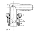
- the second embodiment of FIG 8 and 9 provided that the insert 4 in two parts the inner ring chamber 14 from a base part 4a and one for the retaining ring element 10 having the receiving part 4b is executed.
- the receiving part is advantageous here 4b with the base part 4a via a positive Snap connection connected. It is also advantageous if then the snap connection through the inserted plug shaft 6 is additionally blocked against loosening.
- this is achieved in that the receiving part 4b with a A large number of axially distributed over the circumference Locking arms 38 engages in the base part 4a, each Locking arm with a locking lug protruding radially outwards engages positively behind a locking edge in the base part 4a.
- plug shaft 6 is inserted, this is a movement the locking arms 38 excluded radially inwards. Based 8, this can be easily understood.
- the insert 4 in Fig. 10 with its preferably up to the lower edge of the insert 4, the external thread 12 in a threaded bore (standard bore) of a housing part, not shown Screw.
- This variation allows the necessary screwing depth to be reduced to the minimum screw-in depth of a standard bore can be adapted. That points to Insert part 4 for sealing against the housing part on a seal 40.
- Both 1 to 9 is mainly a radial seal, while in the embodiment of FIG. 10, the seal 40 as an axial seal is executed. It is advantageous in this case to engage in the external thread section 12 Flange section with larger radial width in comparison to FIGS. 1 to 9 connects.
- radial or axial sealing can be used.
- the annular groove 16 of the plug shaft 6 on its by the free shaft end remote side has an upper flank, which is preferred is designed as a slope 42, so that in the event of an impact load in Insertion direction on the plug part 2, the retaining ring element 10 via the slope 42nd is spread radially elastic and then springs back again. This will Damage to the retaining ring element 10 with such impact loads avoided.
- the base part 4a preferably made of metal, in particular Brass, while the receiving part 4b then preferably consists of a suitable plastic is produced.
- the retaining ring element 10 also exists preferably made of plastic.
Landscapes
- Engineering & Computer Science (AREA)
- General Engineering & Computer Science (AREA)
- Mechanical Engineering (AREA)
- Quick-Acting Or Multi-Walled Pipe Joints (AREA)
- Connector Housings Or Holding Contact Members (AREA)
Description
- Fig. 1
- einen Längsschnitt durch einen erfindungsgemäßen Steckverbinder in einer ersten Ausführungsform,
- Fig. 2
- eine perspektivische Explosionsdarstellung der Einzelteile des Steckverbinders in der Ausführung nach Fig. 1,
- Fig. 3
- eine etwas vergrößerte Ansicht des Halteringelementes in Pfeilrichtung III gemäß Fig. 2,
- Fig. 4
- eine Ansicht des Halteringelementes in Pfeilrichtung IV gemäß Fig. 3,
- Fig. 5
- eine weitere Ansicht des Halteringelementes in Pfeilrichtung V gemäß Fig. 4,
- Fig. 6
- eine vergrößerte Schnittansicht des Halteringelementes in der Ebene VI-VI gemäß Fig. 5,
- Fig. 7
- eine weitere Perspektivansicht des Halteringelementes aus anderer Blickrichtung im Vergleich zu Fig. 2,
- Fig. 8
- eine zweite Ausführungsform des erfindungsgemäßen Steckverbinders in einer Schnittdarstellung analog zu Fig. 1,
- Fig. 9
- eine perspektivische Explosionsdarstellung der Ausführungsform nach Fig. 8,
- Fig. 10
- eine dritte Ausführungsform des Steckverbinders im Schnitt analog zu Fig. 1 bzw. 8 und
- Fig. 11
- eine weitere Schnittdarstellung des Steckverbinders, hier beispielhaft in der Ausführung nach Fig. 8 mit zusätzlicher Darstellung eines Lösewerkzeugs zur Erläuterung des Lösevorgangs.
Claims (15)
- Steckverbinder für Druckleitungen, mit einem Steckerteil (2) und einem lösbar in eine Öffnung eines Gehäuseteils einsetzbaren Einsatzeil (4), wobei das Steckerteil (2) mit einem Steckerschaft (6) dichtend in eine Durchgangsöffnung (8) des Einsatzteils (4) einsteckbar und in der eingesteckten Position über ein radialelastisch verformbares Halteringelement (10) gegen Lösen formschlüssig arretierbar ist, und wobei das Halteringelement (10) in einer inneren Ringkammer (14) des Einsatzteils (4) integriert unverlierbar angeordnet ist,
dadurch gekennzeichnet, dass das Einsatzteil (4) auf der in das Gehäuseteil einzusetzenden Stirnseite derart ausgebildet ist und das Halteringelement (10) zur einzusetzenden Stirnseite hin eine Konusfläche (20) derart aufweist, dass das Halteringelement (10) mit einem hülsenförmig ausgebildeten Löseelement (18) von der Stirnseite her zur Freigabe des Steckerteils (2) durch axialen Andruck über die Konusfläche (20) spreizbar ist. - Steckverbinder nach Anspruch 1,
dadurch gekennzeichnet, dassdas Halteringelement (10) als Kreisringkörper mit einem im Wesentlichen rechteckigen Ringquerschnitt ausgebildet ist und an einer Stelle seines Umfangs durchgehend geschlitzt und dadurch radial elastisch verformbar ausgebildet ist. - Steckverbinder nach Anspruch 1 oder 2,
dadurch gekennzeichnet, dass sich an die Konusfläche (20) des Halteringelementes (10) radial nach innen eine zylindrische Innenfläche (22) derart anschließt, dass das hülsenförmige Löseelement (18) mit einem Endabschnitt in der gespreizten Stellung des Halteringelementes (10) kraftschlüssig in der Innenfläche (22) sitzt. - Steckverbinder nach einem der Ansprüche 1 bis 3,
dadurch gekennzeichnet, dass das Halteringelement (10) über Zentriermittel selbstzentrierend in der Ringkammer (14) sitzt. - Steckverbinder nach Anspruch 4,
dadurch gekennzeichnet, dassdas Halteringelement (10) auf seinem Außenumfang (30) als Zentriermittel mehrere, insbesondere etwa tangential ausgerichtete, elastische Zentrierarme (32) aufweist. - Steckverbinder nach einem der Ansprüche 1 bis 5,
gekennzeichnet durch Einsetzmittel zum selbsttätigen elastischen Verengen des Halteringelementes (10) beim axialen Einsetzten in die innere Ringkammer (14) des Einsatzteils (4). - Steckverbindung nach Anspruch 5 oder 6,
dadurch gekennzeichnet, dass die Zentrierarme (32) auf der axial in Einsetzrichtung weisenden Seite nach außen abfallend abgeschrägt ausgebildet sind. - Steckverbindung nach einem der Ansprüche 1 bis 7,
gekennzeichnet durch Mittel zur Vermeidung einer falsch orientierten Montage des Halteringelementes (10). - Steckverbindung nach einem der Ansprüche 1 bis 8,
dadurch gekennzeichnet, dass das Einsatzteil (4) einstückig und insbesondere aus Metall, vorzugsweise Messing, ausgebildet ist. - Steckverbindung nach einem der Ansprüche 1 bis 8,
dadurch gekennzeichnet, dass das Einsatzteil (4) zweiteilig aus einem Basisteil (4a) und einem die innere Ringkammer (14) für das Halteringelement (10) aufweisenden Aufnahmeteil (4b) ausgeführt ist. - Steckverbindung nach Anspruch 10,
dadurch gekennzeichnet, dass das Aufnahmeteil (4b) mit dem Basisteil (4a) über eine Rastverbindung verbunden ist, wobei vorzugsweise die Rastverbindung durch den eingesteckten Steckerschaft (6) gegen Lösen blockiert wird. - Steckverbinder nach einem der Ansprüche 1 bis 11,
dadurch gekennzeichnet, dass das Einsatzteil (4) ein Außengewinde (12) aufweist. - Steckverbinder nach einem der Ansprüche 1 bis 12,
dadurch gekennzeichnet, dass das Einsatzteil (4) zur Abdichtung gegen das Gehäuseteil eine axial und/oder radial wirkende Dichtung (40) aufweist. - Steckverbinder nach einem der Ansprüche 1 bis 13,
dadurch gekennzeichnet, dass das Halteringelement (10) und/oder das Aufnahmeteil (4b) aus Kunststoff bestehen/besteht. - Steckverbinder nach einem der Ansprüche 1 bis 14,
dadurch gekennzeichnet, dassder Steckerschaft (6) des Steckerteils (2) eine äußere Ringnut (16) zum Eingreifen des Halteringelementes (10) aufweist, wobei eine obere Flanke der Ringnut (16) derart als Schräge (42) ausgebildet ist, dass bei einer Schlagbelastung in Einsteckrichtung auf das Steckerteil (2) das Halteringelement (10) zur Vermeidung von Beschädigungen radial elastisch nachgibt und zurückfedert.
Applications Claiming Priority (2)
| Application Number | Priority Date | Filing Date | Title |
|---|---|---|---|
| DE29913750U | 1999-08-06 | ||
| DE29913750U DE29913750U1 (de) | 1999-08-06 | 1999-08-06 | Steckverbinder für Druckleitungssysteme |
Publications (2)
| Publication Number | Publication Date |
|---|---|
| EP1074782A1 EP1074782A1 (de) | 2001-02-07 |
| EP1074782B1 true EP1074782B1 (de) | 2003-05-14 |
Family
ID=8077180
Family Applications (1)
| Application Number | Title | Priority Date | Filing Date |
|---|---|---|---|
| EP00114074A Expired - Lifetime EP1074782B1 (de) | 1999-08-06 | 2000-07-07 | Steckverbinder für Druckleitungssysteme |
Country Status (2)
| Country | Link |
|---|---|
| EP (1) | EP1074782B1 (de) |
| DE (2) | DE29913750U1 (de) |
Families Citing this family (3)
| Publication number | Priority date | Publication date | Assignee | Title |
|---|---|---|---|---|
| DE10221246B4 (de) * | 2002-05-13 | 2006-03-16 | Vag-Armaturen Gmbh | Armatur, insbesondere Tausch-Schieber |
| DE20215593U1 (de) | 2002-10-10 | 2004-03-11 | Voss Automotive Gmbh | Aufnahmeteil einer Fluid-Steckverbindung |
| JP2015197195A (ja) * | 2014-04-03 | 2015-11-09 | ニッタ株式会社 | 狭所配管用継手 |
Family Cites Families (4)
| Publication number | Priority date | Publication date | Assignee | Title |
|---|---|---|---|---|
| DE2824943C2 (de) * | 1978-06-07 | 1986-07-31 | Armaturenfabrik Hermann Voss GmbH + Co, 5272 Wipperfürth | Anschlußvorrichtung für Bremsleitungen |
| DE3341029A1 (de) * | 1982-06-16 | 1985-05-23 | Armaturenfabrik Hermann Voss GmbH + Co, 5272 Wipperfürth | Steckverbindung fuer mit einem druckmittel beaufschlagbare systeme |
| IT1170404B (it) * | 1982-06-16 | 1987-06-03 | Voss Armaturen | Collegamento a spina per impianti caricati con fluido in pressione |
| CA2004975A1 (en) * | 1988-12-16 | 1990-06-16 | Lawrence F. Hayman | Quick connect/disconnect fluid coupling |
-
1999
- 1999-08-06 DE DE29913750U patent/DE29913750U1/de not_active Expired - Lifetime
-
2000
- 2000-07-07 EP EP00114074A patent/EP1074782B1/de not_active Expired - Lifetime
- 2000-07-07 DE DE50002150T patent/DE50002150D1/de not_active Expired - Lifetime
Also Published As
| Publication number | Publication date |
|---|---|
| DE29913750U1 (de) | 2000-12-14 |
| EP1074782A1 (de) | 2001-02-07 |
| DE50002150D1 (de) | 2003-06-18 |
Similar Documents
| Publication | Publication Date | Title |
|---|---|---|
| DE69111223T3 (de) | Steckverbinder-Vorrichtung. | |
| CH648392A5 (de) | Anschlussverbindungsstueck fuer leitungen zum fuehren von gasfoermigen oder fluessigen medien. | |
| WO1999019119A1 (de) | Betätigungswerkzeug | |
| EP1540234B1 (de) | Adapter-zwischenring für ein einschraubteil eines fluid-stecksystems | |
| DE102007051263B4 (de) | Optische Steckverbindung | |
| EP0185802B1 (de) | Verbindungsvorrichtung für Druckleitungen mit unverlierbarem Haltering | |
| DE10125499C1 (de) | Steckverbindung, insbesondere für Rohrleitungen | |
| EP1074782B1 (de) | Steckverbinder für Druckleitungssysteme | |
| DE19515849B4 (de) | Steckkupplung für Druckmittel-Leitungen | |
| EP1549873B1 (de) | Aufnahmeteil einer fluid-steckverbindung | |
| EP1006307B1 (de) | Steckkupplung | |
| DE19705167C5 (de) | Steckverbindung für Rohrleitungen | |
| DE3235125C2 (de) | ||
| DE3341030C2 (de) | ||
| EP1936252A1 (de) | Anschlussvorrichtung für Medienleitungen | |
| DE202006019525U1 (de) | Blockverbinder für Fluidleitungen | |
| DE3235059A1 (de) | Steckkupplung fuer druckleitungen, insbesondere kunststoffleitungen fuer bremssysteme fuer kraftfahrzeuge | |
| DE4032594C2 (de) | Verschlußeinrichtung zum Verbinden zweier Bauteile | |
| DE102005038439A1 (de) | Steckverbindung für Fluid-Leitungen | |
| EP0692344B1 (de) | Montageelement für ein Einsatzteil insbesondere einer Druckleitungs-Anschlussvorrichtung | |
| DE202007004204U1 (de) | Anschlussvorrichtung für Medienleitungen | |
| DE102022206571A1 (de) | Fluidanschlusseinrichtung | |
| EP0860642B1 (de) | Druckmittel-Steckkupplung | |
| DE29901674U1 (de) | Steckkupplung | |
| DE202004012794U1 (de) | Steckverbindung für Fluid-Leitungen |
Legal Events
| Date | Code | Title | Description |
|---|---|---|---|
| PUAI | Public reference made under article 153(3) epc to a published international application that has entered the european phase |
Free format text: ORIGINAL CODE: 0009012 |
|
| AK | Designated contracting states |
Kind code of ref document: A1 Designated state(s): DE FR IT NL SE |
|
| AX | Request for extension of the european patent |
Free format text: AL;LT;LV;MK;RO;SI |
|
| 17P | Request for examination filed |
Effective date: 20010411 |
|
| AKX | Designation fees paid |
Free format text: DE FR IT NL SE |
|
| 17Q | First examination report despatched |
Effective date: 20020531 |
|
| RAP1 | Party data changed (applicant data changed or rights of an application transferred) |
Owner name: VOSS AUTOMOTIVE GMBH |
|
| GRAH | Despatch of communication of intention to grant a patent |
Free format text: ORIGINAL CODE: EPIDOS IGRA |
|
| GRAH | Despatch of communication of intention to grant a patent |
Free format text: ORIGINAL CODE: EPIDOS IGRA |
|
| GRAA | (expected) grant |
Free format text: ORIGINAL CODE: 0009210 |
|
| AK | Designated contracting states |
Designated state(s): DE FR IT NL SE |
|
| REG | Reference to a national code |
Ref country code: SE Ref legal event code: TRGR |
|
| REF | Corresponds to: |
Ref document number: 50002150 Country of ref document: DE Date of ref document: 20030618 Kind code of ref document: P |
|
| ET | Fr: translation filed | ||
| PLBE | No opposition filed within time limit |
Free format text: ORIGINAL CODE: 0009261 |
|
| STAA | Information on the status of an ep patent application or granted ep patent |
Free format text: STATUS: NO OPPOSITION FILED WITHIN TIME LIMIT |
|
| 26N | No opposition filed |
Effective date: 20040217 |
|
| PGFP | Annual fee paid to national office [announced via postgrant information from national office to epo] |
Ref country code: FR Payment date: 20090731 Year of fee payment: 10 |
|
| PGFP | Annual fee paid to national office [announced via postgrant information from national office to epo] |
Ref country code: NL Payment date: 20090730 Year of fee payment: 10 |
|
| REG | Reference to a national code |
Ref country code: NL Ref legal event code: V1 Effective date: 20110201 |
|
| REG | Reference to a national code |
Ref country code: FR Ref legal event code: ST Effective date: 20110331 |
|
| PG25 | Lapsed in a contracting state [announced via postgrant information from national office to epo] |
Ref country code: NL Free format text: LAPSE BECAUSE OF NON-PAYMENT OF DUE FEES Effective date: 20110201 Ref country code: FR Free format text: LAPSE BECAUSE OF NON-PAYMENT OF DUE FEES Effective date: 20100802 |
|
| PGFP | Annual fee paid to national office [announced via postgrant information from national office to epo] |
Ref country code: SE Payment date: 20130726 Year of fee payment: 14 |
|
| PGFP | Annual fee paid to national office [announced via postgrant information from national office to epo] |
Ref country code: IT Payment date: 20130725 Year of fee payment: 14 |
|
| REG | Reference to a national code |
Ref country code: SE Ref legal event code: EUG |
|
| PG25 | Lapsed in a contracting state [announced via postgrant information from national office to epo] |
Ref country code: IT Free format text: LAPSE BECAUSE OF NON-PAYMENT OF DUE FEES Effective date: 20140707 |
|
| PG25 | Lapsed in a contracting state [announced via postgrant information from national office to epo] |
Ref country code: SE Free format text: LAPSE BECAUSE OF NON-PAYMENT OF DUE FEES Effective date: 20140708 |
|
| PGFP | Annual fee paid to national office [announced via postgrant information from national office to epo] |
Ref country code: DE Payment date: 20150928 Year of fee payment: 16 |
|
| REG | Reference to a national code |
Ref country code: DE Ref legal event code: R119 Ref document number: 50002150 Country of ref document: DE |
|
| PG25 | Lapsed in a contracting state [announced via postgrant information from national office to epo] |
Ref country code: DE Free format text: LAPSE BECAUSE OF NON-PAYMENT OF DUE FEES Effective date: 20170201 |