EP1005837A2 - Endovascular electrolytically detachable wire for thrombus formation - Google Patents
Endovascular electrolytically detachable wire for thrombus formation Download PDFInfo
- Publication number
- EP1005837A2 EP1005837A2 EP00104781A EP00104781A EP1005837A2 EP 1005837 A2 EP1005837 A2 EP 1005837A2 EP 00104781 A EP00104781 A EP 00104781A EP 00104781 A EP00104781 A EP 00104781A EP 1005837 A2 EP1005837 A2 EP 1005837A2
- Authority
- EP
- European Patent Office
- Prior art keywords
- wire
- tip
- aneurysm
- distal end
- coil
- Prior art date
- Legal status (The legal status is an assumption and is not a legal conclusion. Google has not performed a legal analysis and makes no representation as to the accuracy of the status listed.)
- Granted
Links
- 208000007536 Thrombosis Diseases 0.000 title description 24
- 230000015572 biosynthetic process Effects 0.000 title description 9
- 238000005868 electrolysis reaction Methods 0.000 claims abstract description 21
- 239000012530 fluid Substances 0.000 claims abstract description 20
- 230000007246 mechanism Effects 0.000 claims abstract description 10
- 238000002955 isolation Methods 0.000 claims abstract description 7
- 229920000728 polyester Polymers 0.000 claims description 10
- 206010002329 Aneurysm Diseases 0.000 description 57
- BASFCYQUMIYNBI-UHFFFAOYSA-N platinum Chemical compound [Pt] BASFCYQUMIYNBI-UHFFFAOYSA-N 0.000 description 46
- 229910001220 stainless steel Inorganic materials 0.000 description 29
- 239000010935 stainless steel Substances 0.000 description 25
- 229910052697 platinum Inorganic materials 0.000 description 23
- 230000002792 vascular Effects 0.000 description 20
- 238000000034 method Methods 0.000 description 15
- 210000004369 blood Anatomy 0.000 description 13
- 239000008280 blood Substances 0.000 description 13
- 210000001367 artery Anatomy 0.000 description 12
- 239000003550 marker Substances 0.000 description 11
- 210000004209 hair Anatomy 0.000 description 10
- 238000011282 treatment Methods 0.000 description 10
- 201000008450 Intracranial aneurysm Diseases 0.000 description 8
- 238000005755 formation reaction Methods 0.000 description 8
- 238000001356 surgical procedure Methods 0.000 description 7
- 238000013459 approach Methods 0.000 description 6
- 230000010102 embolization Effects 0.000 description 6
- 230000017531 blood circulation Effects 0.000 description 5
- 239000004809 Teflon Substances 0.000 description 4
- 229920006362 Teflon® Polymers 0.000 description 4
- 239000000853 adhesive Substances 0.000 description 4
- 230000001070 adhesive effect Effects 0.000 description 4
- 230000008878 coupling Effects 0.000 description 4
- 238000010168 coupling process Methods 0.000 description 4
- 238000005859 coupling reaction Methods 0.000 description 4
- 239000000835 fiber Substances 0.000 description 4
- 238000002347 injection Methods 0.000 description 4
- 239000007924 injection Substances 0.000 description 4
- 238000003780 insertion Methods 0.000 description 4
- 230000037431 insertion Effects 0.000 description 4
- QRWOVIRDHQJFDB-UHFFFAOYSA-N isobutyl cyanoacrylate Chemical compound CC(C)COC(=O)C(=C)C#N QRWOVIRDHQJFDB-UHFFFAOYSA-N 0.000 description 4
- 230000002829 reductive effect Effects 0.000 description 4
- 238000000926 separation method Methods 0.000 description 4
- 102000008946 Fibrinogen Human genes 0.000 description 3
- 108010049003 Fibrinogen Proteins 0.000 description 3
- XEEYBQQBJWHFJM-UHFFFAOYSA-N Iron Chemical compound [Fe] XEEYBQQBJWHFJM-UHFFFAOYSA-N 0.000 description 3
- 210000001772 blood platelet Anatomy 0.000 description 3
- 230000015271 coagulation Effects 0.000 description 3
- 238000005345 coagulation Methods 0.000 description 3
- 210000003743 erythrocyte Anatomy 0.000 description 3
- 230000005294 ferromagnetic effect Effects 0.000 description 3
- 229940012952 fibrinogen Drugs 0.000 description 3
- 238000002594 fluoroscopy Methods 0.000 description 3
- 238000013467 fragmentation Methods 0.000 description 3
- 238000006062 fragmentation reaction Methods 0.000 description 3
- 210000000265 leukocyte Anatomy 0.000 description 3
- 239000007788 liquid Substances 0.000 description 3
- 230000033001 locomotion Effects 0.000 description 3
- 239000013307 optical fiber Substances 0.000 description 3
- 239000000523 sample Substances 0.000 description 3
- 206010003226 Arteriovenous fistula Diseases 0.000 description 2
- 206010016717 Fistula Diseases 0.000 description 2
- 239000004831 Hot glue Substances 0.000 description 2
- 208000009443 Vascular Malformations Diseases 0.000 description 2
- 230000002776 aggregation Effects 0.000 description 2
- 238000004220 aggregation Methods 0.000 description 2
- 210000004556 brain Anatomy 0.000 description 2
- 239000011248 coating agent Substances 0.000 description 2
- 238000000576 coating method Methods 0.000 description 2
- 239000003814 drug Substances 0.000 description 2
- 230000003890 fistula Effects 0.000 description 2
- 238000002695 general anesthesia Methods 0.000 description 2
- 210000004013 groin Anatomy 0.000 description 2
- 201000002877 intracranial berry aneurysm Diseases 0.000 description 2
- 239000000155 melt Substances 0.000 description 2
- 239000004005 microsphere Substances 0.000 description 2
- 239000000203 mixture Substances 0.000 description 2
- 230000003287 optical effect Effects 0.000 description 2
- 230000008569 process Effects 0.000 description 2
- 230000002787 reinforcement Effects 0.000 description 2
- 230000000717 retained effect Effects 0.000 description 2
- 229910000679 solder Inorganic materials 0.000 description 2
- 210000003462 vein Anatomy 0.000 description 2
- 206010000060 Abdominal distension Diseases 0.000 description 1
- 206010053567 Coagulopathies Diseases 0.000 description 1
- RYGMFSIKBFXOCR-UHFFFAOYSA-N Copper Chemical compound [Cu] RYGMFSIKBFXOCR-UHFFFAOYSA-N 0.000 description 1
- 208000031238 Intracranial haemangioma Diseases 0.000 description 1
- 241001465754 Metazoa Species 0.000 description 1
- 239000004698 Polyethylene Substances 0.000 description 1
- 229910001260 Pt alloy Inorganic materials 0.000 description 1
- 208000004717 Ruptured Aneurysm Diseases 0.000 description 1
- 208000005392 Spasm Diseases 0.000 description 1
- 229910000831 Steel Inorganic materials 0.000 description 1
- 206010047163 Vasospasm Diseases 0.000 description 1
- 230000009471 action Effects 0.000 description 1
- 229910045601 alloy Inorganic materials 0.000 description 1
- 239000000956 alloy Substances 0.000 description 1
- 210000000576 arachnoid Anatomy 0.000 description 1
- 238000010420 art technique Methods 0.000 description 1
- 229910052790 beryllium Inorganic materials 0.000 description 1
- ATBAMAFKBVZNFJ-UHFFFAOYSA-N beryllium atom Chemical compound [Be] ATBAMAFKBVZNFJ-UHFFFAOYSA-N 0.000 description 1
- 230000023555 blood coagulation Effects 0.000 description 1
- 210000001627 cerebral artery Anatomy 0.000 description 1
- 230000002490 cerebral effect Effects 0.000 description 1
- 239000003795 chemical substances by application Substances 0.000 description 1
- 230000035602 clotting Effects 0.000 description 1
- 230000001112 coagulating effect Effects 0.000 description 1
- 239000004020 conductor Substances 0.000 description 1
- 239000000470 constituent Substances 0.000 description 1
- 229910052802 copper Inorganic materials 0.000 description 1
- 239000010949 copper Substances 0.000 description 1
- 238000007428 craniotomy Methods 0.000 description 1
- 230000003247 decreasing effect Effects 0.000 description 1
- 230000007547 defect Effects 0.000 description 1
- 230000003111 delayed effect Effects 0.000 description 1
- 238000004925 denaturation Methods 0.000 description 1
- 230000036425 denaturation Effects 0.000 description 1
- 201000010099 disease Diseases 0.000 description 1
- 208000037265 diseases, disorders, signs and symptoms Diseases 0.000 description 1
- 238000002224 dissection Methods 0.000 description 1
- 238000009826 distribution Methods 0.000 description 1
- 230000000694 effects Effects 0.000 description 1
- 238000002474 experimental method Methods 0.000 description 1
- 238000007429 general method Methods 0.000 description 1
- PCHJSUWPFVWCPO-UHFFFAOYSA-N gold Chemical compound [Au] PCHJSUWPFVWCPO-UHFFFAOYSA-N 0.000 description 1
- 229910052737 gold Inorganic materials 0.000 description 1
- 239000010931 gold Substances 0.000 description 1
- 238000000227 grinding Methods 0.000 description 1
- 230000006872 improvement Effects 0.000 description 1
- 238000007917 intracranial administration Methods 0.000 description 1
- 230000009545 invasion Effects 0.000 description 1
- 229910052742 iron Inorganic materials 0.000 description 1
- 230000001788 irregular Effects 0.000 description 1
- 238000003475 lamination Methods 0.000 description 1
- 230000000670 limiting effect Effects 0.000 description 1
- 238000002690 local anesthesia Methods 0.000 description 1
- 230000005291 magnetic effect Effects 0.000 description 1
- 238000012423 maintenance Methods 0.000 description 1
- 125000002496 methyl group Chemical group [H]C([H])([H])* 0.000 description 1
- 238000002406 microsurgery Methods 0.000 description 1
- 230000036961 partial effect Effects 0.000 description 1
- 239000002245 particle Substances 0.000 description 1
- -1 polyethylene Polymers 0.000 description 1
- 229920000573 polyethylene Polymers 0.000 description 1
- 230000000379 polymerizing effect Effects 0.000 description 1
- 238000004321 preservation Methods 0.000 description 1
- 230000001681 protective effect Effects 0.000 description 1
- 102000004169 proteins and genes Human genes 0.000 description 1
- 108090000623 proteins and genes Proteins 0.000 description 1
- 230000000246 remedial effect Effects 0.000 description 1
- 210000004761 scalp Anatomy 0.000 description 1
- 239000007787 solid Substances 0.000 description 1
- 239000010959 steel Substances 0.000 description 1
- 239000000725 suspension Substances 0.000 description 1
- 230000001732 thrombotic effect Effects 0.000 description 1
- 231100000331 toxic Toxicity 0.000 description 1
- 230000002588 toxic effect Effects 0.000 description 1
- 230000000007 visual effect Effects 0.000 description 1
Images


Classifications
-
- A—HUMAN NECESSITIES
- A61—MEDICAL OR VETERINARY SCIENCE; HYGIENE
- A61M—DEVICES FOR INTRODUCING MEDIA INTO, OR ONTO, THE BODY; DEVICES FOR TRANSDUCING BODY MEDIA OR FOR TAKING MEDIA FROM THE BODY; DEVICES FOR PRODUCING OR ENDING SLEEP OR STUPOR
- A61M25/00—Catheters; Hollow probes
- A61M25/01—Introducing, guiding, advancing, emplacing or holding catheters
- A61M25/09—Guide wires
-
- A—HUMAN NECESSITIES
- A61—MEDICAL OR VETERINARY SCIENCE; HYGIENE
- A61B—DIAGNOSIS; SURGERY; IDENTIFICATION
- A61B17/00—Surgical instruments, devices or methods
- A61B17/12—Surgical instruments, devices or methods for ligaturing or otherwise compressing tubular parts of the body, e.g. blood vessels or umbilical cord
- A61B17/12022—Occluding by internal devices, e.g. balloons or releasable wires
- A61B17/12099—Occluding by internal devices, e.g. balloons or releasable wires characterised by the location of the occluder
- A61B17/12109—Occluding by internal devices, e.g. balloons or releasable wires characterised by the location of the occluder in a blood vessel
- A61B17/12113—Occluding by internal devices, e.g. balloons or releasable wires characterised by the location of the occluder in a blood vessel within an aneurysm
-
- A—HUMAN NECESSITIES
- A61—MEDICAL OR VETERINARY SCIENCE; HYGIENE
- A61B—DIAGNOSIS; SURGERY; IDENTIFICATION
- A61B17/00—Surgical instruments, devices or methods
- A61B17/12—Surgical instruments, devices or methods for ligaturing or otherwise compressing tubular parts of the body, e.g. blood vessels or umbilical cord
- A61B17/12022—Occluding by internal devices, e.g. balloons or releasable wires
- A61B17/12131—Occluding by internal devices, e.g. balloons or releasable wires characterised by the type of occluding device
- A61B17/1214—Coils or wires
- A61B17/12145—Coils or wires having a pre-set deployed three-dimensional shape
-
- A—HUMAN NECESSITIES
- A61—MEDICAL OR VETERINARY SCIENCE; HYGIENE
- A61B—DIAGNOSIS; SURGERY; IDENTIFICATION
- A61B17/00—Surgical instruments, devices or methods
- A61B17/12—Surgical instruments, devices or methods for ligaturing or otherwise compressing tubular parts of the body, e.g. blood vessels or umbilical cord
- A61B17/12022—Occluding by internal devices, e.g. balloons or releasable wires
- A61B17/12131—Occluding by internal devices, e.g. balloons or releasable wires characterised by the type of occluding device
- A61B17/1214—Coils or wires
- A61B17/1215—Coils or wires comprising additional materials, e.g. thrombogenic, having filaments, having fibers, being coated
-
- A—HUMAN NECESSITIES
- A61—MEDICAL OR VETERINARY SCIENCE; HYGIENE
- A61B—DIAGNOSIS; SURGERY; IDENTIFICATION
- A61B18/00—Surgical instruments, devices or methods for transferring non-mechanical forms of energy to or from the body
- A61B18/04—Surgical instruments, devices or methods for transferring non-mechanical forms of energy to or from the body by heating
- A61B18/12—Surgical instruments, devices or methods for transferring non-mechanical forms of energy to or from the body by heating by passing a current through the tissue to be heated, e.g. high-frequency current
- A61B18/14—Probes or electrodes therefor
- A61B18/1492—Probes or electrodes therefor having a flexible, catheter-like structure, e.g. for heart ablation
-
- A—HUMAN NECESSITIES
- A61—MEDICAL OR VETERINARY SCIENCE; HYGIENE
- A61B—DIAGNOSIS; SURGERY; IDENTIFICATION
- A61B17/00—Surgical instruments, devices or methods
- A61B17/00234—Surgical instruments, devices or methods for minimally invasive surgery
- A61B2017/00292—Surgical instruments, devices or methods for minimally invasive surgery mounted on or guided by flexible, e.g. catheter-like, means
-
- A—HUMAN NECESSITIES
- A61—MEDICAL OR VETERINARY SCIENCE; HYGIENE
- A61B—DIAGNOSIS; SURGERY; IDENTIFICATION
- A61B17/00—Surgical instruments, devices or methods
- A61B17/12—Surgical instruments, devices or methods for ligaturing or otherwise compressing tubular parts of the body, e.g. blood vessels or umbilical cord
- A61B17/12022—Occluding by internal devices, e.g. balloons or releasable wires
- A61B2017/1205—Introduction devices
- A61B2017/12054—Details concerning the detachment of the occluding device from the introduction device
- A61B2017/12063—Details concerning the detachment of the occluding device from the introduction device electrolytically detachable
-
- A—HUMAN NECESSITIES
- A61—MEDICAL OR VETERINARY SCIENCE; HYGIENE
- A61B—DIAGNOSIS; SURGERY; IDENTIFICATION
- A61B17/00—Surgical instruments, devices or methods
- A61B17/12—Surgical instruments, devices or methods for ligaturing or otherwise compressing tubular parts of the body, e.g. blood vessels or umbilical cord
- A61B17/12022—Occluding by internal devices, e.g. balloons or releasable wires
- A61B2017/1205—Introduction devices
- A61B2017/12054—Details concerning the detachment of the occluding device from the introduction device
- A61B2017/12095—Threaded connection
-
- A—HUMAN NECESSITIES
- A61—MEDICAL OR VETERINARY SCIENCE; HYGIENE
- A61B—DIAGNOSIS; SURGERY; IDENTIFICATION
- A61B17/00—Surgical instruments, devices or methods
- A61B17/22—Implements for squeezing-off ulcers or the like on inner organs of the body; Implements for scraping-out cavities of body organs, e.g. bones; for invasive removal or destruction of calculus using mechanical vibrations; for removing obstructions in blood vessels, not otherwise provided for
- A61B2017/22038—Implements for squeezing-off ulcers or the like on inner organs of the body; Implements for scraping-out cavities of body organs, e.g. bones; for invasive removal or destruction of calculus using mechanical vibrations; for removing obstructions in blood vessels, not otherwise provided for with a guide wire
-
- A—HUMAN NECESSITIES
- A61—MEDICAL OR VETERINARY SCIENCE; HYGIENE
- A61B—DIAGNOSIS; SURGERY; IDENTIFICATION
- A61B18/00—Surgical instruments, devices or methods for transferring non-mechanical forms of energy to or from the body
- A61B2018/00636—Sensing and controlling the application of energy
- A61B2018/00666—Sensing and controlling the application of energy using a threshold value
- A61B2018/00678—Sensing and controlling the application of energy using a threshold value upper
-
- A—HUMAN NECESSITIES
- A61—MEDICAL OR VETERINARY SCIENCE; HYGIENE
- A61B—DIAGNOSIS; SURGERY; IDENTIFICATION
- A61B18/00—Surgical instruments, devices or methods for transferring non-mechanical forms of energy to or from the body
- A61B2018/00636—Sensing and controlling the application of energy
- A61B2018/00696—Controlled or regulated parameters
- A61B2018/00761—Duration
-
- A—HUMAN NECESSITIES
- A61—MEDICAL OR VETERINARY SCIENCE; HYGIENE
- A61B—DIAGNOSIS; SURGERY; IDENTIFICATION
- A61B18/00—Surgical instruments, devices or methods for transferring non-mechanical forms of energy to or from the body
- A61B2018/00636—Sensing and controlling the application of energy
- A61B2018/00773—Sensed parameters
- A61B2018/00875—Resistance or impedance
-
- A—HUMAN NECESSITIES
- A61—MEDICAL OR VETERINARY SCIENCE; HYGIENE
- A61B—DIAGNOSIS; SURGERY; IDENTIFICATION
- A61B18/00—Surgical instruments, devices or methods for transferring non-mechanical forms of energy to or from the body
- A61B2018/00636—Sensing and controlling the application of energy
- A61B2018/00773—Sensed parameters
- A61B2018/00886—Duration
-
- A—HUMAN NECESSITIES
- A61—MEDICAL OR VETERINARY SCIENCE; HYGIENE
- A61B—DIAGNOSIS; SURGERY; IDENTIFICATION
- A61B18/00—Surgical instruments, devices or methods for transferring non-mechanical forms of energy to or from the body
- A61B18/04—Surgical instruments, devices or methods for transferring non-mechanical forms of energy to or from the body by heating
- A61B18/12—Surgical instruments, devices or methods for transferring non-mechanical forms of energy to or from the body by heating by passing a current through the tissue to be heated, e.g. high-frequency current
- A61B18/1206—Generators therefor
- A61B2018/1226—Generators therefor powered by a battery
-
- A—HUMAN NECESSITIES
- A61—MEDICAL OR VETERINARY SCIENCE; HYGIENE
- A61B—DIAGNOSIS; SURGERY; IDENTIFICATION
- A61B18/00—Surgical instruments, devices or methods for transferring non-mechanical forms of energy to or from the body
- A61B18/04—Surgical instruments, devices or methods for transferring non-mechanical forms of energy to or from the body by heating
- A61B18/12—Surgical instruments, devices or methods for transferring non-mechanical forms of energy to or from the body by heating by passing a current through the tissue to be heated, e.g. high-frequency current
- A61B18/1206—Generators therefor
- A61B2018/1246—Generators therefor characterised by the output polarity
- A61B2018/1253—Generators therefor characterised by the output polarity monopolar
-
- A—HUMAN NECESSITIES
- A61—MEDICAL OR VETERINARY SCIENCE; HYGIENE
- A61B—DIAGNOSIS; SURGERY; IDENTIFICATION
- A61B18/00—Surgical instruments, devices or methods for transferring non-mechanical forms of energy to or from the body
- A61B18/04—Surgical instruments, devices or methods for transferring non-mechanical forms of energy to or from the body by heating
- A61B18/12—Surgical instruments, devices or methods for transferring non-mechanical forms of energy to or from the body by heating by passing a current through the tissue to be heated, e.g. high-frequency current
- A61B18/1206—Generators therefor
- A61B2018/1246—Generators therefor characterised by the output polarity
- A61B2018/126—Generators therefor characterised by the output polarity bipolar
-
- A—HUMAN NECESSITIES
- A61—MEDICAL OR VETERINARY SCIENCE; HYGIENE
- A61B—DIAGNOSIS; SURGERY; IDENTIFICATION
- A61B18/00—Surgical instruments, devices or methods for transferring non-mechanical forms of energy to or from the body
- A61B18/04—Surgical instruments, devices or methods for transferring non-mechanical forms of energy to or from the body by heating
- A61B18/12—Surgical instruments, devices or methods for transferring non-mechanical forms of energy to or from the body by heating by passing a current through the tissue to be heated, e.g. high-frequency current
- A61B18/1206—Generators therefor
- A61B2018/1266—Generators therefor with DC current output
-
- A—HUMAN NECESSITIES
- A61—MEDICAL OR VETERINARY SCIENCE; HYGIENE
- A61B—DIAGNOSIS; SURGERY; IDENTIFICATION
- A61B18/00—Surgical instruments, devices or methods for transferring non-mechanical forms of energy to or from the body
- A61B18/04—Surgical instruments, devices or methods for transferring non-mechanical forms of energy to or from the body by heating
- A61B18/12—Surgical instruments, devices or methods for transferring non-mechanical forms of energy to or from the body by heating by passing a current through the tissue to be heated, e.g. high-frequency current
- A61B18/14—Probes or electrodes therefor
- A61B2018/1405—Electrodes having a specific shape
- A61B2018/1435—Spiral
-
- A—HUMAN NECESSITIES
- A61—MEDICAL OR VETERINARY SCIENCE; HYGIENE
- A61B—DIAGNOSIS; SURGERY; IDENTIFICATION
- A61B18/00—Surgical instruments, devices or methods for transferring non-mechanical forms of energy to or from the body
- A61B18/04—Surgical instruments, devices or methods for transferring non-mechanical forms of energy to or from the body by heating
- A61B18/12—Surgical instruments, devices or methods for transferring non-mechanical forms of energy to or from the body by heating by passing a current through the tissue to be heated, e.g. high-frequency current
- A61B18/14—Probes or electrodes therefor
- A61B2018/1495—Electrodes being detachable from a support structure
-
- A—HUMAN NECESSITIES
- A61—MEDICAL OR VETERINARY SCIENCE; HYGIENE
- A61B—DIAGNOSIS; SURGERY; IDENTIFICATION
- A61B90/00—Instruments, implements or accessories specially adapted for surgery or diagnosis and not covered by any of the groups A61B1/00 - A61B50/00, e.g. for luxation treatment or for protecting wound edges
- A61B90/39—Markers, e.g. radio-opaque or breast lesions markers
- A61B2090/3966—Radiopaque markers visible in an X-ray image
-
- A—HUMAN NECESSITIES
- A61—MEDICAL OR VETERINARY SCIENCE; HYGIENE
- A61B—DIAGNOSIS; SURGERY; IDENTIFICATION
- A61B90/00—Instruments, implements or accessories specially adapted for surgery or diagnosis and not covered by any of the groups A61B1/00 - A61B50/00, e.g. for luxation treatment or for protecting wound edges
- A61B90/39—Markers, e.g. radio-opaque or breast lesions markers
-
- A—HUMAN NECESSITIES
- A61—MEDICAL OR VETERINARY SCIENCE; HYGIENE
- A61M—DEVICES FOR INTRODUCING MEDIA INTO, OR ONTO, THE BODY; DEVICES FOR TRANSDUCING BODY MEDIA OR FOR TAKING MEDIA FROM THE BODY; DEVICES FOR PRODUCING OR ENDING SLEEP OR STUPOR
- A61M25/00—Catheters; Hollow probes
- A61M25/01—Introducing, guiding, advancing, emplacing or holding catheters
- A61M25/09—Guide wires
- A61M2025/09175—Guide wires having specific characteristics at the distal tip
Definitions
- the invention relates to mechanical mechanism to maintain an object, as a coil, in the human body in presence of an ionic fluid, and an apparatus for occluding a body cavity in the presence of said ionic fluid, to form an occlusion within a vascular novelty.
- the extravascular approach is comprised of surgery or microsurgery of the aneurysm or treatment site for the purpose of preserving the parent artery.
- This treatment is common with intracranial berry aneurysms.
- the methodology comprises the step of clipping the neck of the aneurysm, performing a suture-ligation of the neck, or wrapping the entire aneurysm.
- Each of these surgical procedures is performed by intrusive invasion into the body and performed from outside the aneurysm or target site.
- General anesthesia, craniotomy, brain retraction and arachnoid dissection around the neck of the aneurysm and placement of a clip are typically required in these surgical procedures.
- Surgical treatment of vascular intracranial aneurysm can expect a mortality rate of 4-8% with a morbidity rate of 18-20%. Because of the mortality and morbidity rate expected, the surgical procedure is often delayed while waiting for the best surgical time with the result that an additional percentage of patients will die from the underlying disease or defect prior to surgery. For this reason the prior art has sought alternative means of treatment.
- microcatheters In the endovascular approach, the interior of the aneurysm is entered through the use of a microcatheter. Recently developed microcatheters, such as those shown by Engelson, "Catheter Guidewire”, U.S. Patent 4,884,579 and as described in Engelson, “Catheter for Guidewire Tracking", U.S. Patent 4,739,768 (1988), allow navigation into the cerebral arteries and entry into a cranial aneurysm.
- a balloon is typically attached to the end of the microcatheter and it is possible to introduce the balloon into the aneurysm, inflate it, and detach it, leaving it to occlude the sac and neck with preservation of the parent artery.
- endovascular balloon embolization of berry aneurysms is an attractive method in situations where an extravascular surgical approach is difficult, inflation of a balloon into the aneurysm carries some risk of aneurysm rupture due to possible over-distention of portions of the sac and due to the traction produced while detaching the balloon.
- an ideal embolizing agent should adapt itself to the irregular shape of the internal walls of the aneurysm.
- the aneurysmal wall must conform to the shape of the balloon. This may not lead to a satisfactory result and further increases the risk of rupture
- an aneurysm is surgically exposed or stereotaxically reached with a probe.
- the wall of the aneurysm is then perforated from the outside and various techniques are used to occlude the interior in order to prevent it from rebleeding.
- These prior art techniques include electrothrombosis, isobutyl-cyanoacrylate embolization, hog-hair embolization and ferromagnetic thrombosis.
- the tip of a positively charged electrode is inserted surgically into the interior of the aneurysm.
- An application of the positive charge attracts white blood cells, red blood cells, platelets and fibrinogen which are typically negatively charged at the normal pH of the blood
- the thrombic mass is then formed in the aneurysm about the tip. Thereafter, the tip is removed.
- Mullan "Experiences with Surgical Thrombosis of Intracranial Berry Aneurysms and Carotid Cavenous Fistulas", J. Neurosurg., Vol. 41, December 1974; Hosobuchi, "Electrothrombosis Carotid-Cavernous Fistula', J.
- the prior art has also devised the use of a liquid adhesive, isobutylcyanoacrylate (IBCA) which polymerizes rapidly on contact with blood to form a firm mass.
- IBCA isobutylcyanoacrylate
- the liquid adhesive is injected into the aneurysm by puncturing the sac with a small needle.
- blood flow through the parent artery must be momentarily reduced or interrupted.
- an inflated balloon may be placed in the artery at the level of the neck of the aneurysm for injection.
- the risks of seepage of such a polymerizing adhesive into the parent artery exists, if it is not completely blocked with consequent occlusion of the artery.
- the prior art has utilized an air gun to inject hog hair through the aneurysm wall to induce internal thrombosis.
- the success of this procedure involves exposing the aneurysm sufficiently to allow air gun injection and has not been convincingly shown as successful for thrombic formations.
- Ferromagnetic thrombosis in the prior art in extra-intravascular treatments comprises the stereotactic placement of a magnetic probe against the sac of the aneurysm followed by injection into the aneurysm by an injecting needle of iron microspheres. Aggregation of the microspheres through the extravascular magnet is followed by interneuysmatic thrombus. This treatment has not been entirely successful because of the risk of fragmentation of the metallic thrombus when the extravascular magnet is removed. Suspension of the iron powder in methyl methymethacrylate has been used to prevent fragmentation.
- the treatment has not been favored, because of the need to puncture the aneurysm, the risk of occlusion of the parent artery, the use of unusual and expensive equipment, the need for a craniectomy and general anesthesia, and the necessity to penetrate cerebral tissue to reach the aneurysm.
- Endovascular coagulation of blood is also well known in the art and a device using laser optically generated heat is shown by O'Reilly, "Optical Fiber with Attachable Metallic Tip for Intravascular Laser Coagulation of Arteries, Veins, Aneurysms, Vascular Malformation and Arteriovenous Fistulas", U.S. Patent 4,735,201 (1988). See also, O'Reilly et al., “Laser Induced Thermal Occlusion of Berry Aneurysms : Initial Experimental Results", Radiology, Vol. 171, No. 2, pages 471-74 (1989). O'Reilly places a tip into an aneurysm by means of an endovascular microcatheter.
- the tip is adhesively bonded to an optic fiber disposed through the microcatheter.
- Optical energy is transmitted along the optic fiber from a remote laser at the proximal end of the microcatheter.
- the optical energy heasts the tip to cauterize the tissue surrounding the neck of the aneurysm or other vascular opening to be occluded.
- the catheter is provided with a balloon located on or adjacent to its distal end to cut off blood flow to the site to be cauterized and occluded. Normally, the blood flow would carry away the heat at the catheter tip, thereby preventing cauterization.
- the heat in the tip also serves to melt the adhesive used to secure the tip to the distal end of the optical fiber. If all goes well, the tip can be separated from the optical fiber and left in place in the neck of the aneurysm, provided that the cauterization is complete at the same time as the hot melt adhesive melts.
- a thrombus is not formed from the heated tip. Instead, blood tissue surrounding the tip is coagulated. Coagulation is a denaturation of protein to form a connective-like tissue similar to that which occurs when the albumen of an egg is heated and coagulates from a clear running liquid to an opaque white solid. The tissue characteristics and composition of the coagulated tissue is therefore substantially distinct from the thrombosis which is formed by the thrombotic aggregation of white and red blood cells, platelets and fibrinogen. The coagulative tissue is substantially softer than a thrombic mass and can therefore more easily be dislodged.
- O'Reilly's device depends at least in part upon the successful cauterization timed to occur no later than the detachment of the heat tip from the optic fiber.
- the heated tip must also be proportionally sized to the neck of the aneurysm in order to effectively coagulate the tissue surrounding it to form a blockage at the neck. It is believed that the tissue in the interior of the aneurysm remains substantially uncoagulated.
- the hot melt adhesive attaching the tip to the optic fiber melts and is dispersed into the adjacent blood tissue where it resolidifies to form free particles within the intracranial blood stream with much the same disadvantages which result from fragmentation of a ferromagnetic electrothrombosis.
- the invention is a mechanical mechanism to maintain an object in the human body in presence of an ionic fluid comprising :
- said isolation from electrolysis is due to a mechanical coupler interposed between the object and said electrolytically severable tip.
- the mechanical coupler comprises a drop of polyester.
- the object comprises a loosely wound coil.
- the invention is also an apparatus for occluding a body cavity in the presence of an ionic fluid comprising :
- said object is isolated from electrolysis in said ionic fluid by isolation from said wire.
- the object is isolated from said wire by interposition of a mechanical coupler between said wire and said object.
- said mechanical coupler interposed between said wire and the object is a drop of polyester.
- the invention is also an apparatus for occluding a body cavity in the presence of an ionic fluid comprising :
- the object is not subject to electrolysis in said ionic fluid by virtue of isolation of said object from said wire, the object is electrically isolated from said wire by interposition of a mechanical coupler between said wire and said object, and said mechanical coupler interposed between said wire and object is a drop of polyester.
- An artery, vein, aneurysm, vascular malformation or arterial fistula is occluded through endovascular occlusion by the endovascular insertion of a platinum tip into the vascular cavity.
- the vascular cavity is packed with the tip to obstruct blood flow or access of blood in the cavity such that the blood clots in the cavity and an occlusion if formed.
- the tip may be elongate and flexible so that it packs the cavity by being folded upon itself a multiple number of times, or may pack the cavity by virtue of a filamentary or fuzzy structure of the tip. The tip is then separated from the wire mechanically or by electrolytic separation of the tip from the wire.
- the wire and the microcatheter are thereafter removed leaving the tip embedded in the thrombus formed within the vascular cavity. Movement of wire in the microcatheter is more easily tracked by providing a radioopaque proximal marker on the microcatheter and a corresponding indicator marker on the wire. Electrothrombosis is facilitate by placing the ground electrode on the distal end of the microcatheter and flowing current between the microcatheter electrode and the tip.
- a portion of the wire connected between the tip and the body of the wire is comprised of stainless steel and exposed to the bloodstream so that upon continued application of a positive current to the exposed portion, the exposed portion is corroded away at least at one location and the tip is separated from the body of the wire.
- Figure 1 is an enlarged side view of a first embodiment of the distal end of a prior art wire and tip shown in partial cross-sectional view.
- a conventional Teflon laminated or similarly insulated stainless steel wire 10 is disposed within a protective microcatheter (not shown).
- Stainless steel wire 10 is approximately 0.010-0.020 inch (0.254-0.508 mn) in diameter.
- wire 10 is tapered at its distal end to form a conical section 12 which joins a section 14 of reduced diameter which extends longitudinally along a length 16 of wire 10. Section 16 then narrows gradually down to a thin threadlike portion 18 beginning at a first bonding location 20 and ending at a second bonding location 22.
- the stainless steel wire 10 comprised of that portion disposed within the microcatheter body, tapered section 12, reduced diameter section 16 and threadlike section 18, is collectively referred to as a core wire which typically is 50-300 cm. in length.
- the portion of the core wire extending from tapered section 12 to second bonding location 22 is collectively referred to as the grinding length and may typically be between 20 and 50 cm. in length.
- Reduced diameter portion 14 and at least part of sections 12 and first bonding location 20 may be covered with an insulating Teflon laminate 24 which encapsulates the underlying portion of wire 10 to prevent contact with the blood.
- a stainless steel coil 26 is soldered to the proximate end of threadlike portion 18 of wire 10 at first bonding location 20.
- Stainless steel coil 26 is typically 3 to 10 cm. in length and like wire 10 has a diameter typically between 0.010 to 0.020 inch (0.254-0.508 mm).
- the distal end of stainless steel coil 26 is soldered to the distal end of threadlike portion 18 of wire 10 and to the proximal end of a platinum secondary coil 28 at second bonding location 22.
- Secondary coil 28 itself forms a spiral or helix typically between 2 to 10 mm. in diameter.
- the helical envelope formed by secondary coil 28 may be cylindrical or conical.
- secondary coil 28 is between approximately 0.010 and 0.020 inch (0.254-0.508 mm) in diameter.
- the diameter of the wire itself forming stainless steel coil 26 and coil 28 is approximately between 0.001-0.005 inch.
- the distal end of secondary coil 28 is provided with a platinum soldered tip 30 to form a rounded and smooth termination to avoid puncturing the aneurysm or tearing tissue.
- secondary coil 28 Although prebiased to form a cylindrical or conical envelope, secondary coil 28 is extremely soft and its overall shape is easily deformed. When inserted within the microcatheter (not shown), secondary coil 28 is easily straightened to lie axially within the microcatheter. Once disposed out of the tip of the microcatheter, secondary coil 28 forms the shape shown in figure 1 and may similarly be loosely deformed to the interior shape of the aneurysm.
- a direct current is applied to wire 10 from a voltage source exterior to the body.
- the positive charge on secondary coil 28 within the cavity of the aneurysm causes a thrombus to form within the aneurysm by electrothrombosis.
- Detachment of the tip occurs either : (1) by continued application of current for a predetermined time when the portion 18 is exposed to blood ; or (2) by movement of the wire to expose portion 18 to blood followed by continued current application for a predetermined time.
- both threadlike portion and stainless steel coil 26 will be completely disintegrated at least at one point, thereby allowing wire 10 to be withdrawn from the vascular space while leaving secondary coil 28 embedded within the thrombus formed within the aneurysm.
- FIG. 2 illustrates in enlarged partially cross-sectional view a second prior art embodiment.
- Stainless steel core 32 terminates in a conical distal portion 34.
- Stainless steel coil 36 shown in cross-sectional view, is soldered to distal portion 3.4. of wire 32 at bonding location 38.
- the opposing end of the stainless steel coil 36 is provided with a soldered, rounded platinum tip 40.
- stainless steel core wire 32 is approximately 0.25 mm in diameter with the length of stainless steel coil 36 being approximately 8 cm. with the longitudinal length of platinum tip 40 being between 3 and 10 mm.
- the total length of wire 32 from tip 40 to the proximate end is approximately 150 cm.
- the embodiment of figure 2 is utilized in exactly the same manner as described above in connection with figure 1 to form a thrombic mass within an aneurysm or other vascular cavity.
- the embodiment of figure 2 is distinguished from that shown in figure 1 by the absence of the extension of stainless core 32 through coil 36 to tip 40. In the case of the embodiment of figure 2 no inner core or reinforcement is provided within stainless steel coil 36.
- Threadlike portion 18 is provided in the embodiment of figure 1 to allow increased tensile strength of the wire. However, a degree of flexibility of the wire is sacrificed by the inclusion even of threadlike tip 18, so that the embodiment of figure 2 provides a more flexible tip, at least for that portion of the micro-guidewire constituting the stainless steel coil 36.
- Thinned and threadlike portion guidewires disposed concentrically within coiled portions are well known and are shown in Antoshkiw, "Disposable Guidewire", U.S. Patent 3,789,841 (1974) ; Sepetka et al., "Guidewire Device", US. Patent 4,832,047 (1989); Engelson, "Catheter Guidewire”, U.S. Patent 4,884,579 (1989); Samson et al., "Guidewire for Catheters” , U.S. Patent 4,538,622 (1985); and Samson et al.," “Catheter Guidewire with Short Spring Tip and Method of Using the Same", U.S. Patent 4,554,929 (1985).
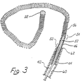
- FIG 3 shows an enlarged side view of a wire, generally denoted by reference numeral 42, disposed within a microcatheter 44 shown in cross-sectional view.
- a stainless steel coil 46 is soldered to a conical portion 48 of wire 22 at a first bonding location 50.
- a thin threadlike extension 52 is then longitudinally disposed within stainless steel coil 46 to a second bonding location 54 where stainless steel wire 46 and threadlike portion 52 are soldered to a soft platinum coil 56.
- Platinum coil 56 is not prebiased, nor does it contain any internal reinforcement, but is a free and open coil similar in that respect to stainless steel coil 36 of the embodiment of figure 2.
- platinum coil 56 is particularly distinguished by its length of approximately 1 to 50 cm. and by its flexibility.
- the platinum or platinum alloy used is particularly pliable and the diameter of the wire used to form platinum coil 56 is approximately 0.025-0.13 mm inch in diameter.
- the distal end of platinum coil 56 is provided with a smooth and rounded platinum tip 58 similar in that respect to tips 30 and 40 of figures 1 and 2, respectively.
- microcatheter 44 When coil 56 is disposed within microcatheter 44, it lies along the longitudinal lumen 60 defined by microcatheter 44.
- the distal end 62 of microcatheter 60 is then placed into the neck of the aneurysm and the wire 42 is advanced, thereby feeding tip 58 in platinum coil 56 into aneurysm 64 until bonding location 50 resides in the neck of the aneurysm as best depicted in the diagrammatic cross-sectional view of figure 4.
- Figure 4 illustrates the insertion of the embodiment of figure 3 within a vessel 66 with distal tip of microcatheter 44 positioned near neck 68 of aneurysm 64.
- Coil 56 is fed into aneurysm 64 until at least a portion of stainless steel coil 46 is exposed beyond the distal tip 62 of microcatheter 44.
- a positive electric current of approximately 0.01 to 2 milliamps at 0.1 - 6 volts is applied to wire 42 to form the thrombus. Typically a thrombus will form within three to five minutes.
- the negative pole 72 of voltage source 70 is typically placed over and in contact with the skin.
- tip 58 and coil 56 are detached from wire 42 by electrolytic disintegration of at least one portion of stainless steel coil 46. In the illustrated embodiment this is accomplished by continued application of current until the total time of current application is almost approximately four minutes.
- At least one portion of stainless steel coil 46 will be completely dissolved through by electrolytic action within 3 to 10 minutes, usually about 4 minutes.
- wire 42, microcatheter 44 and the remaining portion of coil 46 still attached to wire 42 are removed from vessel 66, leaving aneurysm 64 completely occluded as diagrammatically depicted in figure 5 by thrombus 74. It will be appreciated that the time of disintegration may be varied by altering the dimensions of the portions of the wire and/or the current.
- the process is practiced under fluoroscopic control with local anesthesia at the groin.
- a transfemoral microcatheter is utilized to treat the cerebral aneurysm.
- the platinum is not affected by electrolysis and the remaining portions of the microcatheter are insulated either by a Teflon lamination directly on wire 42 and/or by microcatheter 44. Only the exposed portion of the wire 46 is affected by the electrolysis.
- thrombus 74 continues to form even after detachment from wire 42. It is believed that a positive charge is retained on or near coil 56 which therefore continues to attract platelets, white blood cells, red blood cells and fibrinogen within aneurysm 64.
- Wire 10 has a tapering end portion 14 covered with a Teflon laminate 24 similar to that described in connection with the embodiment of figure 1.
- Wire 10 is attached by means of a mechanical coupling 100 to a platinum coil 102 which has a plurality of filaments or fine hairs 104 extending therefrom.
- hairs 104 have a length as may be determined from the size of the vascular cavity in which coil 102 is to be used. For example, in a small vessel hair lengths of up to 1 mm are contemplated.
- An example of polyester filaments or hairs attached to a coil which was not used in electrothrombosis may be seen in US-A-5,226,911 entitled Vasoocclusion Coil with Attached Fiberous Elements.
- Coil 102 has sufficient length and flexibility that it can be inserted or coiled loosely into the vascular cavity.
- the length of coil 102 need not be so long that the coil itself is capable of being multiply folded on itself and fill or substantially fill the vascular cavity.
- Hairs 104 extending from coil 102 serve to substantially pack, fill or at least impede blood flow or access in the vascular cavity.
- Hairs 104 which are generally inclined backwardly away from extreme tip 106 when delivered, are thus easily able to slide forward with little friction through restrictions in the vessels and aneurysm. Additionally, hairs 104 do not have sufficient length, strength or sharpness to provide any substantial risk or potential for a puncture of the thin vascular wall.
- the plurality of hairs 104 when coiled within the vascular cavity, provide an extremely large surface for attachment of blood constituents to encourage and enhance the formation of a mechanical occlusion within the vascular opening.
- coil 102 is mechanically coupled to thin tapered portion 14 of wire 10 means 10 by means of a small drop of polyester 100.
- Polyester may be substituted for the gold solder of the previously described embodiments in order to reduce concern or risk of toxic reactions in the body.
- Tip portion 14 may also be mechanically separated from wire 10 by means other than electrolysis.
- One method is make the connection between tip 104 and wire 10 by means of a spring loaded mechanical clasp (not shown). The clasps are retained on tip 104 as long as the clasps remain inside of the catheter, but spring open and release tip 104 when extended from the catheter. The catheter and clasps may then be removed from the insertion site.
- This type of mechanical connection is described in US-A-5,304,195 entitled, "Detachable Pusher-Vasoocclusive Coil Assembly with Interlocking Coupling".
- wire 10 and tip portion 104 screw into each other and can be unscrewed from each other by rotation of the catheter or wire with respect to tip 104.
- An extendable sheath (not shown) in the microcatheter is advanced to seize tip 104 to prevent its rotation with wire 10 during the unscrewing process.
- This type of mechanical connection is described in US-A-5,234,437 entitled “Detachable Pusher-Vasoocclusive Coil Assembly with Threaded Coupling", which is incorporated herein by reference and assigned to Target Therapeutics Inc.
- tip 104 may be effected by electrolysis.
- the electrolysing current may be concentrated on the sacrificial stainless steel portion of tip 104 by disposition of an insulative coating on the remaining platinum portion,
- tip 104 may be provided with a polyethylene coating save at least a portion of the stainless steel length. This has the effect of decreasing the time required to electrolytically sufficiently disintegrate the steel portion to allow detachment of the platinum tip, which is an advantageous feature in those cases where a large aneurysm must be treated and a multiple number of coils must be deployed within the aneurysm.
- FIG. 7 illustrates an improvement of, for example, the embodiment of figures 4 and 5.
- Microcatheter 144 is positioned so that its distal end 162 within vessel 66 is positioned at the opening aneurysm 64.
- Microcatheter 144 is provided with radiopaque marker 108 at distal tip 162, a tip marker.
- Radiopaque markes 108 and 110 are, for example, in the form of radiopaque rings made of platinum, approximately 1-3 mm in longitudinal length along the axis of microcatheter 144. Rings 110 and 108 are typically separated by about 3 cm on microcatheter 144.
- wire 10 has a radiopaque marker 112 defined on it such that marker 112 on wire 10 is approximately with aligned with marker 110 on microcatheter 14 when coil 56 is fully deployed into aneurysm 64.
- Distal marker 108 on microcatheter 144 is used to facilitate the location of the microcatheter tip, which can often be obscured by the coils which have been previously deployed.
- the coils are a varying lengths depending on the application or size of the aneurysm or vascular cavity being treated. Coil lengths of 4-40 cm are common. Therefore, even though the thinness of coil 56 may make it difficult to see under standard fluoroscopy and even though the fineness of wire 10 may similarly be obscured or partly obscured, radiopaque markers 108, 110 and 112 are clearly visible. Manipulation of wire 10 to proximal marker 110 can then easily be observed under conventional fluoroscopy even when there are some loss of resolution or fluoroscopic visual obstruction of the coil.
- FIG. 9 illustrates an alternative embodiment wherein microcatheter 144 is supplied with an end electrode 114 coupled to an electrical conductor 116 disposed along the length of microcatheter 144. Wire 116 is ultimately led back to voltage source 70 so that ring electrode 114 is used as the cathode during electrothrombosis instead of an exterior skin electrode 72.
- the electrical currents and electrical currents paths which are set up during the electrothrombosis formation are local to the site of application which allows even smaller currents and voltages to be used to initiate electrothrombosis than in the situation when an exterior skin electrode must be utilized.
- the electrothrombosic current distributions are also better controlled and localized to the site of the thrombus formation. The possibility of stray thrombus formation occurring at unwanted sites or uncontrolled and possibly unwanted electrical current patterns being established elsewhere in the brain or body is therefore largely avoided.
- the shape of the tip or distal platinum coil used in combination with the wire according to the invention may be provided with a variety of shapes and envelopes.
- the composition of the micro-guidewire tip may be made of elements other than platinum including stainless steel, beryllium, copper and various alloys of the same with or without platinum.
- the diameter of the wire, various of the wire described above and the stainless steel coil immediately proximal to the detachable tip may be provided with differing diameters or cross sections to vary the times and current magnitudes necessary in order to effectuate electrolytic detachment from the tip.
- the invention may include conventional electronics connected to the proximal end of the wire for determining the exact instant of detachment of he distal tip from the wire.
Landscapes
- Health & Medical Sciences (AREA)
- Life Sciences & Earth Sciences (AREA)
- Surgery (AREA)
- Engineering & Computer Science (AREA)
- Animal Behavior & Ethology (AREA)
- Biomedical Technology (AREA)
- Heart & Thoracic Surgery (AREA)
- General Health & Medical Sciences (AREA)
- Public Health (AREA)
- Veterinary Medicine (AREA)
- Medical Informatics (AREA)
- Molecular Biology (AREA)
- Nuclear Medicine, Radiotherapy & Molecular Imaging (AREA)
- Reproductive Health (AREA)
- Vascular Medicine (AREA)
- Hematology (AREA)
- Anesthesiology (AREA)
- Pulmonology (AREA)
- Biophysics (AREA)
- Neurosurgery (AREA)
- Cardiology (AREA)
- Physics & Mathematics (AREA)
- Plasma & Fusion (AREA)
- Otolaryngology (AREA)
- Surgical Instruments (AREA)
- Pharmaceuticals Containing Other Organic And Inorganic Compounds (AREA)
- Acyclic And Carbocyclic Compounds In Medicinal Compositions (AREA)
- Prostheses (AREA)
- Media Introduction/Drainage Providing Device (AREA)
- Organic Low-Molecular-Weight Compounds And Preparation Thereof (AREA)
- Dental Preparations (AREA)
- Nonmetallic Welding Materials (AREA)
- Electrotherapy Devices (AREA)
Abstract
- said object (102,104) having a proximal end and a distal end (106), and
- an electrolytically severable tip (14) situated to release said
object upon application of electrolysis to said electrolytically severable tip,
characterized in that said object is isolated from electrolysis in said ionic fluid.
Description
- The invention relates to mechanical mechanism to maintain an object, as a coil, in the human body in presence of an ionic fluid, and an apparatus for occluding a body cavity in the presence of said ionic fluid, to form an occlusion within a vascular novelty.
- Approximately 25,000 intracranial aneurysms rupture every year in North America. The primary purpose of treatment for ruptured intracranial aneurysm is to prevent rebleeding. At the present time, three general methods of treatment exist, namely an extravascular, endovascular and extra-endovascular approach.
- The extravascular approach is comprised of surgery or microsurgery of the aneurysm or treatment site for the purpose of preserving the parent artery. This treatment is common with intracranial berry aneurysms. The methodology comprises the step of clipping the neck of the aneurysm, performing a suture-ligation of the neck, or wrapping the entire aneurysm. Each of these surgical procedures is performed by intrusive invasion into the body and performed from outside the aneurysm or target site. General anesthesia, craniotomy, brain retraction and arachnoid dissection around the neck of the aneurysm and placement of a clip are typically required in these surgical procedures. Surgical treatment of vascular intracranial aneurysm can expect a mortality rate of 4-8% with a morbidity rate of 18-20%. Because of the mortality and morbidity rate expected, the surgical procedure is often delayed while waiting for the best surgical time with the result that an additional percentage of patients will die from the underlying disease or defect prior to surgery. For this reason the prior art has sought alternative means of treatment.
- In the endovascular approach, the interior of the aneurysm is entered through the use of a microcatheter. Recently developed microcatheters, such as those shown by Engelson, "Catheter Guidewire", U.S. Patent 4,884,579 and as described in Engelson, "Catheter for Guidewire Tracking", U.S. Patent 4,739,768 (1988), allow navigation into the cerebral arteries and entry into a cranial aneurysm.
- In such procedures a balloon is typically attached to the end of the microcatheter and it is possible to introduce the balloon into the aneurysm, inflate it, and detach it, leaving it to occlude the sac and neck with preservation of the parent artery. While endovascular balloon embolization of berry aneurysms is an attractive method in situations where an extravascular surgical approach is difficult, inflation of a balloon into the aneurysm carries some risk of aneurysm rupture due to possible over-distention of portions of the sac and due to the traction produced while detaching the balloon.
- While remedial procedures exist for treating a ruptured aneurysm during classical extravascular surgery, no satisfactory methodology exists if the aneurysm breaks during an endovascular balloon embolization.
- Furthermore, an ideal embolizing agent should adapt itself to the irregular shape of the internal walls of the aneurysm. On the contrary, in a balloon embolization the aneurysmal wall must conform to the shape of the balloon. This may not lead to a satisfactory result and further increases the risk of rupture
- Still further balloon embolization is not always possible. If the diameter of the deflated balloon is too great to enter the intracerebral arteries, especially in the cases where there is a vasospasm, complications with ruptured intracranial aneurysms may occur. The procedure then must be deferred until the spasm is resolved and this then incurs a risk of rebleeding.
- In the extra-intravascular approach, an aneurysm is surgically exposed or stereotaxically reached with a probe. The wall of the aneurysm is then perforated from the outside and various techniques are used to occlude the interior in order to prevent it from rebleeding. These prior art techniques include electrothrombosis, isobutyl-cyanoacrylate embolization, hog-hair embolization and ferromagnetic thrombosis.
- In the use of electrothrombosis for extra-intravascular treatment the tip of a positively charged electrode is inserted surgically into the interior of the aneurysm. An application of the positive charge attracts white blood cells, red blood cells, platelets and fibrinogen which are typically negatively charged at the normal pH of the blood The thrombic mass is then formed in the aneurysm about the tip. Thereafter, the tip is removed. See Mullan, "Experiences with Surgical Thrombosis of Intracranial Berry Aneurysms and Carotid Cavenous Fistulas", J. Neurosurg., Vol. 41, December 1974; Hosobuchi, "Electrothrombosis Carotid-Cavernous Fistula', J. Neurosurg., Vol. 42, January 1975 ; Araki et al., "Electrically Induced Thrombosis for the Treatment of Intracranial Aneurysms and Angiomas", Excerpta Medica International Congress Series, Amsterdam 1965, Vol. 110, 651-654; Sawyer et al., "Bio-Electric Phenomena as an Etiological Factor in Intravascular Thrombosis", Am. J. Physiol., Vol. 175, 103-107 (1953) ; J Piton et al., "Selective Vascular Thrombosis Induced by a Direct Electrical Current ; Animal Experiments", J. Neuroradiology, Vol. 5, pages 139-152 (1978). However, each of these techniques involves some type of intrusive procedure to approach the aneurysm from the exterior of the body.
- The prior art has also devised the use of a liquid adhesive, isobutylcyanoacrylate (IBCA) which polymerizes rapidly on contact with blood to form a firm mass. The liquid adhesive is injected into the aneurysm by puncturing the sac with a small needle. In order to avoid spillage into the parent artery during IBCA injection, blood flow through the parent artery must be momentarily reduced or interrupted. Alternatively, an inflated balloon may be placed in the artery at the level of the neck of the aneurysm for injection. In addition to the risks caused by temporary blockage of the parent artery, the risks of seepage of such a polymerizing adhesive into the parent artery exists, if it is not completely blocked with consequent occlusion of the artery.
- Still further, the prior art has utilized an air gun to inject hog hair through the aneurysm wall to induce internal thrombosis. The success of this procedure involves exposing the aneurysm sufficiently to allow air gun injection and has not been convincingly shown as successful for thrombic formations.
- Ferromagnetic thrombosis in the prior art in extra-intravascular treatments comprises the stereotactic placement of a magnetic probe against the sac of the aneurysm followed by injection into the aneurysm by an injecting needle of iron microspheres. Aggregation of the microspheres through the extravascular magnet is followed by interneuysmatic thrombus. This treatment has not been entirely successful because of the risk of fragmentation of the metallic thrombus when the extravascular magnet is removed. Suspension of the iron powder in methyl methymethacrylate has been used to prevent fragmentation. The treatment has not been favored, because of the need to puncture the aneurysm, the risk of occlusion of the parent artery, the use of unusual and expensive equipment, the need for a craniectomy and general anesthesia, and the necessity to penetrate cerebral tissue to reach the aneurysm.
- Endovascular coagulation of blood is also well known in the art and a device using laser optically generated heat is shown by O'Reilly, "Optical Fiber with Attachable Metallic Tip for Intravascular Laser Coagulation of Arteries, Veins, Aneurysms, Vascular Malformation and Arteriovenous Fistulas", U.S. Patent 4,735,201 (1988). See also, O'Reilly et al., "Laser Induced Thermal Occlusion of Berry Aneurysms : Initial Experimental Results", Radiology, Vol. 171, No. 2, pages 471-74 (1989). O'Reilly places a tip into an aneurysm by means of an endovascular microcatheter. The tip is adhesively bonded to an optic fiber disposed through the microcatheter. Optical energy is transmitted along the optic fiber from a remote laser at the proximal end of the microcatheter. The optical energy heasts the tip to cauterize the tissue surrounding the neck of the aneurysm or other vascular opening to be occluded. The catheter is provided with a balloon located on or adjacent to its distal end to cut off blood flow to the site to be cauterized and occluded. Normally, the blood flow would carry away the heat at the catheter tip, thereby preventing cauterization. The heat in the tip also serves to melt the adhesive used to secure the tip to the distal end of the optical fiber. If all goes well, the tip can be separated from the optical fiber and left in place in the neck of the aneurysm, provided that the cauterization is complete at the same time as the hot melt adhesive melts.
- A thrombus is not formed from the heated tip. Instead, blood tissue surrounding the tip is coagulated. Coagulation is a denaturation of protein to form a connective-like tissue similar to that which occurs when the albumen of an egg is heated and coagulates from a clear running liquid to an opaque white solid. The tissue characteristics and composition of the coagulated tissue is therefore substantially distinct from the thrombosis which is formed by the thrombotic aggregation of white and red blood cells, platelets and fibrinogen. The coagulative tissue is substantially softer than a thrombic mass and can therefore more easily be dislodged.
- O'Reilly's device depends at least in part upon the successful cauterization timed to occur no later than the detachment of the heat tip from the optic fiber. The heated tip must also be proportionally sized to the neck of the aneurysm in order to effectively coagulate the tissue surrounding it to form a blockage at the neck. It is believed that the tissue in the interior of the aneurysm remains substantially uncoagulated. In addition, the hot melt adhesive attaching the tip to the optic fiber melts and is dispersed into the adjacent blood tissue where it resolidifies to form free particles within the intracranial blood stream with much the same disadvantages which result from fragmentation of a ferromagnetic electrothrombosis.
- Therefore, what is needed is an apparatus and methodology which avoids each of the shortcomings and limitations of the prior art discussed above.
- The invention is a mechanical mechanism to maintain an object in the human body in presence of an ionic fluid comprising :
- said object having a proximal end and a distal end, and
- an electrolytically severable tip situated to release said object upon application of electrolysis to said electrolytically severable tip said object is isolated from electrolysis in said ionic fluid.
- In one embodiment, said isolation from electrolysis is due to a mechanical coupler interposed between the object and said electrolytically severable tip.
- In another embodiment, the mechanical coupler comprises a drop of polyester.
- In another embodiment, the object comprises a loosely wound coil.
- The invention is also an apparatus for occluding a body cavity in the presence of an ionic fluid comprising :
- a wire having a proximal and distal end, said distal end being adapted to be positioned in or near said body cavity, said distal end of said wire being fully insulated except for a selected portion serving as an electrolytic tip;
- a detachable object coupled to said distal end of said wire, distal from said tip, said object adapted to be positioned in said body cavity, said object being electrically isolated from electrolysis in said ionic fluid, where substantially only said tip is electrolyzed when current is applied to said wire.
- In one embodiment, said object is isolated from electrolysis in said ionic fluid by isolation from said wire.
- In another embodiment, the object is isolated from said wire by interposition of a mechanical coupler between said wire and said object.
- In still another embodiment, said mechanical coupler interposed between said wire and the object is a drop of polyester.
- The invention is also an apparatus for occluding a body cavity in the presence of an ionic fluid comprising :
- a wire having a proximal and distal end, said distal end of said wire being insulated ;
- an electrolytic tip coupled to said distal end, said electrolytic tip being insulated at least in part ;
- a detachable object coupled to said electrolytic tip, said object not being subject to electrolysis in said ionic fluid when current is applied to said wire, and where said tip is electrolyzed when current is applied to said wire to separate said object from said wire.
- In particular embodiments, the object is not subject to electrolysis in said ionic fluid by virtue of isolation of said object from said wire, the object is electrically isolated from said wire by interposition of a mechanical coupler between said wire and said object, and said mechanical coupler interposed between said wire and object is a drop of polyester.
- The invention can better be visualized by now turning to the following drawings wherein like elements are referenced by like numerals :
- figure 1 is an enlarged partially cross-sectioned side view of a first embodiment of the distal end of a prior art guidewire and tip ;
- figure 2 is an enlarged longitudinal cross section of a second embodiment of a prior art guidewire and tip ;
- figure 3 is an enlarged side view of a third embodiment of a prior art guidwire and tip with a microcatheter portion cut away in a longitudinal cross-sectional view ;
- figure 4 is a simplified depiction of the wire of figure 3 shown disposed within a simple cranial aneurysm ;
- figure 5 is a depiction of the wire of figure 4 shown after electrolytic detachment of the tip ;
- figure 6 is a plan view of an embodiment of the guidewire and tip portion wherein the type is provided with a plurality of polyester filamentary hairs ;
- figures 7 and 8 are a diagrammatic depictions wherein position markers have been provided on the catheter and wire to assist in proper fluoroscopic manipulation ;
- figure 9 is a simplified cross-sectional view of the catheter and wire showing a ground electrode disposed on the distal tip of the catheter.
- The invention and its various embodiments are best understood by now turning to the following detailed description.
- An artery, vein, aneurysm, vascular malformation or arterial fistula is occluded through endovascular occlusion by the endovascular insertion of a platinum tip into the vascular cavity. The vascular cavity is packed with the tip to obstruct blood flow or access of blood in the cavity such that the blood clots in the cavity and an occlusion if formed. The tip may be elongate and flexible so that it packs the cavity by being folded upon itself a multiple number of times, or may pack the cavity by virtue of a filamentary or fuzzy structure of the tip. The tip is then separated from the wire mechanically or by electrolytic separation of the tip from the wire. The wire and the microcatheter are thereafter removed leaving the tip embedded in the thrombus formed within the vascular cavity. Movement of wire in the microcatheter is more easily tracked by providing a radioopaque proximal marker on the microcatheter and a corresponding indicator marker on the wire. Electrothrombosis is facilitate by placing the ground electrode on the distal end of the microcatheter and flowing current between the microcatheter electrode and the tip.
- When the tip is separated from the wire by electrolytic separation of the tip from the wire, a portion of the wire connected between the tip and the body of the wire is comprised of stainless steel and exposed to the bloodstream so that upon continued application of a positive current to the exposed portion, the exposed portion is corroded away at least at one location and the tip is separated from the body of the wire.
- Figure 1 is an enlarged side view of a first embodiment of the distal end of a prior art wire and tip shown in partial cross-sectional view. A conventional Teflon laminated or similarly insulated
stainless steel wire 10 is disposed within a protective microcatheter (not shown).Stainless steel wire 10 is approximately 0.010-0.020 inch (0.254-0.508 mn) in diameter. In the illustrated embodiment,wire 10 is tapered at its distal end to form a conical section 12 which joins asection 14 of reduced diameter which extends longitudinally along a length 16 ofwire 10. Section 16 then narrows gradually down to a thinthreadlike portion 18 beginning at a first bonding location 20 and ending at asecond bonding location 22. - The
stainless steel wire 10, comprised of that portion disposed within the microcatheter body, tapered section 12, reduced diameter section 16 andthreadlike section 18, is collectively referred to as a core wire which typically is 50-300 cm. in length. - In the illustrated embodiment the portion of the core wire extending from tapered section 12 to
second bonding location 22 is collectively referred to as the grinding length and may typically be between 20 and 50 cm. in length. - Reduced
diameter portion 14 and at least part of sections 12 and first bonding location 20 may be covered with an insulatingTeflon laminate 24 which encapsulates the underlying portion ofwire 10 to prevent contact with the blood. - A
stainless steel coil 26 is soldered to the proximate end ofthreadlike portion 18 ofwire 10 at first bonding location 20.Stainless steel coil 26 is typically 3 to 10 cm. in length and likewire 10 has a diameter typically between 0.010 to 0.020 inch (0.254-0.508 mm). - The distal end of
stainless steel coil 26 is soldered to the distal end ofthreadlike portion 18 ofwire 10 and to the proximal end of a platinumsecondary coil 28 atsecond bonding location 22.Secondary coil 28 itself forms a spiral or helix typically between 2 to 10 mm. in diameter. The helical envelope formed bysecondary coil 28 may be cylindrical or conical. Likewire 10 andstainless steel coil 26,secondary coil 28 is between approximately 0.010 and 0.020 inch (0.254-0.508 mm) in diameter. The diameter of the wire itself formingstainless steel coil 26 andcoil 28 is approximately between 0.001-0.005 inch. - The distal end of
secondary coil 28 is provided with a platinum solderedtip 30 to form a rounded and smooth termination to avoid puncturing the aneurysm or tearing tissue. - Although prebiased to form a cylindrical or conical envelope,
secondary coil 28 is extremely soft and its overall shape is easily deformed. When inserted within the microcatheter (not shown),secondary coil 28 is easily straightened to lie axially within the microcatheter. Once disposed out of the tip of the microcatheter,secondary coil 28 forms the shape shown in figure 1 and may similarly be loosely deformed to the interior shape of the aneurysm. - As will be described below in greater detail in connection with the third embodiment of figure 3, after placement of
secondary coil 28 within the interior of the aneurysm, a direct current is applied to wire 10 from a voltage source exterior to the body. The positive charge onsecondary coil 28 within the cavity of the aneurysm causes a thrombus to form within the aneurysm by electrothrombosis. Detachment of the tip occurs either : (1) by continued application of current for a predetermined time when theportion 18 is exposed to blood ; or (2) by movement of the wire to exposeportion 18 to blood followed by continued current application for a predetermined time. Ultimately, both threadlike portion andstainless steel coil 26 will be completely disintegrated at least at one point, thereby allowingwire 10 to be withdrawn from the vascular space while leavingsecondary coil 28 embedded within the thrombus formed within the aneurysm. - Figure 2 illustrates in enlarged partially cross-sectional view a second prior art embodiment.
Stainless steel core 32 terminates in a conicaldistal portion 34.Stainless steel coil 36, shown in cross-sectional view, is soldered to distal portion 3.4. ofwire 32 atbonding location 38. The opposing end of thestainless steel coil 36 is provided with a soldered,rounded platinum tip 40. In the illustrated embodiment, stainlesssteel core wire 32 is approximately 0.25 mm in diameter with the length ofstainless steel coil 36 being approximately 8 cm. with the longitudinal length ofplatinum tip 40 being between 3 and 10 mm. The total length ofwire 32 fromtip 40 to the proximate end is approximately 150 cm. - The embodiment of figure 2 is utilized in exactly the same manner as described above in connection with figure 1 to form a thrombic mass within an aneurysm or other vascular cavity. The embodiment of figure 2 is distinguished from that shown in figure 1 by the absence of the extension of
stainless core 32 throughcoil 36 to tip 40. In the case of the embodiment of figure 2 no inner core or reinforcement is provided withinstainless steel coil 36.Threadlike portion 18 is provided in the embodiment of figure 1 to allow increased tensile strength of the wire. However, a degree of flexibility of the wire is sacrificed by the inclusion even ofthreadlike tip 18, so that the embodiment of figure 2 provides a more flexible tip, at least for that portion of the micro-guidewire constituting thestainless steel coil 36. - It is expressly understood that the helical secondary coil tip of the embodiment of figure 1 could similarly be attached to
stainless steel coil 36 of the embodiment of figure 2. - Thinned and threadlike portion guidewires disposed concentrically within coiled portions are well known and are shown in Antoshkiw, "Disposable Guidewire", U.S. Patent 3,789,841 (1974) ; Sepetka et al., "Guidewire Device", US. Patent 4,832,047 (1989); Engelson, "Catheter Guidewire", U.S. Patent 4,884,579 (1989); Samson et al., "Guidewire for Catheters" , U.S. Patent 4,538,622 (1985); and Samson et al.," "Catheter Guidewire with Short Spring Tip and Method of Using the Same", U.S. Patent 4,554,929 (1985).
- Turn now to the third prior art embodiment as shown in figure 3. Figure 3 shows an enlarged side view of a wire, generally denoted by
reference numeral 42, disposed within amicrocatheter 44 shown in cross-sectional view. Like the embodiment of figure 1, astainless steel coil 46 is soldered to a conical portion 48 ofwire 22 at afirst bonding location 50. A thinthreadlike extension 52 is then longitudinally disposed withinstainless steel coil 46 to asecond bonding location 54 wherestainless steel wire 46 andthreadlike portion 52 are soldered to asoft platinum coil 56.Platinum coil 56 is not prebiased, nor does it contain any internal reinforcement, but is a free and open coil similar in that respect tostainless steel coil 36 of the embodiment of figure 2. - However,
platinum coil 56 is particularly distinguished by its length of approximately 1 to 50 cm. and by its flexibility. The platinum or platinum alloy used is particularly pliable and the diameter of the wire used to formplatinum coil 56 is approximately 0.025-0.13 mm inch in diameter. The distal end ofplatinum coil 56 is provided with a smooth androunded platinum tip 58 similar in that respect totips - When
coil 56 is disposed withinmicrocatheter 44, it lies along thelongitudinal lumen 60 defined bymicrocatheter 44. Thedistal end 62 ofmicrocatheter 60 is then placed into the neck of the aneurysm and thewire 42 is advanced, thereby feedingtip 58 inplatinum coil 56 intoaneurysm 64 until bondinglocation 50 resides in the neck of the aneurysm as best depicted in the diagrammatic cross-sectional view of figure 4. - Figure 4 illustrates the insertion of the embodiment of figure 3 within a
vessel 66 with distal tip ofmicrocatheter 44 positioned nearneck 68 ofaneurysm 64.Coil 56 is fed intoaneurysm 64 until at least a portion ofstainless steel coil 46 is exposed beyond thedistal tip 62 ofmicrocatheter 44. A positive electric current of approximately 0.01 to 2 milliamps at 0.1 - 6 volts is applied to wire 42 to form the thrombus. Typically a thrombus will form within three to five minutes. Thenegative pole 72 ofvoltage source 70 is typically placed over and in contact with the skin. - After the thrombus has been formed and the aneurysm completely occluded,
tip 58 andcoil 56 are detached fromwire 42 by electrolytic disintegration of at least one portion ofstainless steel coil 46. In the illustrated embodiment this is accomplished by continued application of current until the total time of current application is almost approximately four minutes. - At least one portion of
stainless steel coil 46 will be completely dissolved through by electrolytic action within 3 to 10 minutes, usually about 4 minutes. After separation by electrolytic disintegration,wire 42,microcatheter 44 and the remaining portion ofcoil 46 still attached to wire 42 are removed fromvessel 66, leavinganeurysm 64 completely occluded as diagrammatically depicted in figure 5 bythrombus 74. It will be appreciated that the time of disintegration may be varied by altering the dimensions of the portions of the wire and/or the current. - The process is practiced under fluoroscopic control with local anesthesia at the groin. A transfemoral microcatheter is utilized to treat the cerebral aneurysm. The platinum is not affected by electrolysis and the remaining portions of the microcatheter are insulated either by a Teflon lamination directly on
wire 42 and/or bymicrocatheter 44. Only the exposed portion of thewire 46 is affected by the electrolysis. - It has further been discovered that
thrombus 74 continues to form even after detachment fromwire 42. It is believed that a positive charge is retained on ornear coil 56 which therefore continues to attract platelets, white blood cells, red blood cells and fibrinogen withinaneurysm 64. - Although the foregoing embodiment has been described as forming an occlusion within a blood-filled vascular cavity by means of electrothrombosis, the above disclosure must be read to expressly include formation of the occlusion by mechanical mechanisms without resort to the application of electrical current. A mechanical mechanism which can be safely disposed into the vascular cavity to impede, slow or otherwise initiate clotting of the blood or formation of the occlusion is within the scope of the invention. The insertion within the vascular cavity and maintenance therein of an object with an appropriate blood-clotting characteristics can and does in many cases cause the formation of an occlusion by itself Depicted in figure 6 is an embodiment of the invention wherein such mechanical thrombosis can be achieved.
Wire 10 has a taperingend portion 14 covered with aTeflon laminate 24 similar to that described in connection with the embodiment of figure 1.Wire 10 is attached by means of amechanical coupling 100 to a platinum coil 102 which has a plurality of filaments orfine hairs 104 extending therefrom. In the illustrated embodiment,hairs 104 have a length as may be determined from the size of the vascular cavity in which coil 102 is to be used. For example, in a small vessel hair lengths of up to 1 mm are contemplated. An example of polyester filaments or hairs attached to a coil which was not used in electrothrombosis may be seen in US-A-5,226,911 entitled Vasoocclusion Coil with Attached Fiberous Elements. - Coil 102 has sufficient length and flexibility that it can be inserted or coiled loosely into the vascular cavity. The length of coil 102 need not be so long that the coil itself is capable of being multiply folded on itself and fill or substantially fill the vascular cavity.
Hairs 104 extending from coil 102 serve to substantially pack, fill or at least impede blood flow or access in the vascular cavity.Hairs 104, which are generally inclined backwardly away fromextreme tip 106 when delivered, are thus easily able to slide forward with little friction through restrictions in the vessels and aneurysm. Additionally,hairs 104 do not have sufficient length, strength or sharpness to provide any substantial risk or potential for a puncture of the thin vascular wall. The plurality ofhairs 104, when coiled within the vascular cavity, provide an extremely large surface for attachment of blood constituents to encourage and enhance the formation of a mechanical occlusion within the vascular opening. - In the preferred embodiment, coil 102 is mechanically coupled to thin tapered
portion 14 ofwire 10 means 10 by means of a small drop ofpolyester 100. Polyester may be substituted for the gold solder of the previously described embodiments in order to reduce concern or risk of toxic reactions in the body. -
Tip portion 14 may also be mechanically separated fromwire 10 by means other than electrolysis. One method is make the connection betweentip 104 andwire 10 by means of a spring loaded mechanical clasp (not shown). The clasps are retained ontip 104 as long as the clasps remain inside of the catheter, but spring open andrelease tip 104 when extended from the catheter. The catheter and clasps may then be removed from the insertion site. This type of mechanical connection is described in US-A-5,304,195 entitled, "Detachable Pusher-Vasoocclusive Coil Assembly with Interlocking Coupling". An alternative nonresilient mechanical ball and clasp capturing mechanism is described in US-A-5,261,916 entitled "Detachable Pusher-Vasoocclusive Coil Assembly with Interlocking Ball and Keyway Coupling", which is also incorporated herein by reference and assigned to Target Therapeutics Inc. - In another
embodiment wire 10 and tip portion 104screw into each other and can be unscrewed from each other by rotation of the catheter or wire with respect to tip 104. An extendable sheath (not shown) in the microcatheter is advanced to seizetip 104 to prevent its rotation withwire 10 during the unscrewing process. This type of mechanical connection is described in US-A-5,234,437 entitled "Detachable Pusher-Vasoocclusive Coil Assembly with Threaded Coupling", which is incorporated herein by reference and assigned to Target Therapeutics Inc. - In any case the specific means disclosed here of mechanically detaching
tip 104 fromwire 10 forms no part of the present invention apart from its combination as a whole with other elements of the invention. Specific disclosure of the mechanical means of detachment have been set forth only for the purposes of providing an enabling disclosure of the best mode presently known for practicing the claimed invention. - Even where the occlusion is not formed by electrothrombosis, separation of
tip 104 may be effected by electrolysis. In such situations, the electrolysing current may be concentrated on the sacrificial stainless steel portion oftip 104 by disposition of an insulative coating on the remaining platinum portion, For example,tip 104 may be provided with a polyethylene coating save at least a portion of the stainless steel length. This has the effect of decreasing the time required to electrolytically sufficiently disintegrate the steel portion to allow detachment of the platinum tip, which is an advantageous feature in those cases where a large aneurysm must be treated and a multiple number of coils must be deployed within the aneurysm. - Notwithstanding the fact that
wire 10 and platinum coil 102 in the embodiment figure 6 orwire 10 andplatinum coil Microcatheter 144 is positioned so that itsdistal end 162 withinvessel 66 is positioned at theopening aneurysm 64.Microcatheter 144 is provided withradiopaque marker 108 atdistal tip 162, a tip marker. Moving toward the proximal end ofmicrocatheter 144 is a secondradiopaque marker 110, a proximal marker. Radiopaque markes 108 and 110 are, for example, in the form of radiopaque rings made of platinum, approximately 1-3 mm in longitudinal length along the axis ofmicrocatheter 144.Rings microcatheter 144. Similarly,wire 10 has aradiopaque marker 112 defined on it such thatmarker 112 onwire 10 is approximately with aligned withmarker 110 onmicrocatheter 14 whencoil 56 is fully deployed intoaneurysm 64. Typically, full deployment will place the solder orconnection point 54 of the order of 2-3 mm past opening 68 ofaneurysm 64.Distal marker 108 onmicrocatheter 144 is used to facilitate the location of the microcatheter tip, which can often be obscured by the coils which have been previously deployed. The coils are a varying lengths depending on the application or size of the aneurysm or vascular cavity being treated. Coil lengths of 4-40 cm are common. Therefore, even though the thinness ofcoil 56 may make it difficult to see under standard fluoroscopy and even though the fineness ofwire 10 may similarly be obscured or partly obscured,radiopaque markers wire 10 toproximal marker 110 can then easily be observed under conventional fluoroscopy even when there are some loss of resolution or fluoroscopic visual obstruction of the coil. - Further, in the previous embodiments, such as prior art embodiments shown in figures 4 and 5, when electrothrombosis is used to form the occlusion within
vascular aneurysm 64,coil 56 is used as the electrical anode while the cathode is alarge skin electrode 72 typically conductively applied to the groin or scalp. Figure 9 illustrates an alternative embodiment whereinmicrocatheter 144 is supplied with anend electrode 114 coupled to anelectrical conductor 116 disposed along the length ofmicrocatheter 144.Wire 116 is ultimately led back tovoltage source 70 so thatring electrode 114 is used as the cathode during electrothrombosis instead of anexterior skin electrode 72. With the embodiment of figure 9, the electrical currents and electrical currents paths which are set up during the electrothrombosis formation are local to the site of application which allows even smaller currents and voltages to be used to initiate electrothrombosis than in the situation when an exterior skin electrode must be utilized. The electrothrombosic current distributions are also better controlled and localized to the site of the thrombus formation. The possibility of stray thrombus formation occurring at unwanted sites or uncontrolled and possibly unwanted electrical current patterns being established elsewhere in the brain or body is therefore largely avoided. - It must be understood that the shape of the tip or distal platinum coil used in combination with the wire according to the invention may be provided with a variety of shapes and envelopes. In addition thereto, the composition of the micro-guidewire tip may be made of elements other than platinum including stainless steel, beryllium, copper and various alloys of the same with or without platinum. Still further, the diameter of the wire, various of the wire described above and the stainless steel coil immediately proximal to the detachable tip may be provided with differing diameters or cross sections to vary the times and current magnitudes necessary in order to effectuate electrolytic detachment from the tip. Still further, the invention may include conventional electronics connected to the proximal end of the wire for determining the exact instant of detachment of he distal tip from the wire.
- The reference signs employed in the subsequent claims are not to be construed as limiting the scope of the claims, but to aid understanding.
Claims (12)
- Mechanical mechanism to maintain an object in the human body in presence of an ionic fluid comprising :said object (102,104) having a proximal end and a distal end (106), andan electrolytically severable tip (14) situated to release said object upon application of electrolysis to said electrolytically severable tip,
characterized in that said object is isolated from electrolysis in said ionic fluid. - Mechanical mechanism of claim 1, wherein said isolation from electrolysis is due to a mechanical coupler (100) interposed between the object (102,104) and said electrolytically severable tip (14).
- Mechanical mechanism of claim 2, wherein said mechanical coupler (100) comprises a drop of polyester.
- Mechanical mechanism of claim 1, wherein the object comprises a loosely wound coil (102).
- An apparatus for occluding a body cavity in the presence of an ionic fluid comprising :a wire (10) having a proximal and distal end, said distal end being adapted to be positioned in or near said body cavity, said distal end of said wire being fully insulated (24) except for a selected portion serving as an electrolytic tip (14) ;a detachable object (102,104) coupled to said distal end of said wire (10), distal from said tip, said object adapted to be positioned in said body cavity, said object being electrically isolated from electrolysis in said ionic fluid, where substantially only said tip is electrolyzed when current is applied to said wire.
- The apparatus of claim 5, wherein said object is isolated from electrolysis in said ionic fluid by isolation from said wire.
- The apparatus of claim 6, wherein said object is isolated from said wire by interposition of a mechanical coupler (100) between said wire and said object.
- The apparatus of claim 7, wherein said mechanical coupler (100) interposed between said wire and the object (102, 104) is a drop of polyester.
- An apparatus for occluding a body cavity in the presence of an ionic fluid comprising :a wire (10) having a proximal and distal end, said distal end of said wire being insulated (24) ;an electrolytic tip (14) coupled to said distal end, said electrolytic tip being insulated at least in part ;a detachable object (102,104) coupled to said electrolytic tip, said object not being subject to electrolysis in said ionic fluid when current is applied to said wire, and where said tip is electrolyzed when current is applied to said wire to separate said object from said wire (10).
- The apparatus of claim 9, wherein said object is not subject to electrolysis in said ionic fluid by virtue of isolation of said object from said wire.
- The apparatus of claim 10, wherein said object is electrically isolated from said wire by interposition of a mechanical coupler between said wire and said object.
- The apparatus of claim 11 wherein said mechanical coupler interposed between said wire and object is a drop of polyester.
Priority Applications (2)
| Application Number | Priority Date | Filing Date | Title |
|---|---|---|---|
| EP03010295A EP1366720B1 (en) | 1992-02-24 | 1992-09-30 | Endovascular electrolytically detachable wire for thrombus formation |
| EP03007337A EP1323385A3 (en) | 1992-02-24 | 1992-09-30 | Endovascular electrolytically detachable wire for thrombus formation |
Applications Claiming Priority (4)
| Application Number | Priority Date | Filing Date | Title |
|---|---|---|---|
| US07/840,211 US5354295A (en) | 1990-03-13 | 1992-02-24 | In an endovascular electrolytically detachable wire and tip for the formation of thrombus in arteries, veins, aneurysms, vascular malformations and arteriovenous fistulas |
| US840211 | 1992-02-24 | ||
| EP97112837A EP0803230B1 (en) | 1992-02-24 | 1992-09-30 | Endovascular electrolytically detachable wire for thrombus formation |
| EP92922392A EP0629125B1 (en) | 1992-02-24 | 1992-09-30 | Microcatheter system |
Related Parent Applications (1)
| Application Number | Title | Priority Date | Filing Date |
|---|---|---|---|
| EP97112837A Division EP0803230B1 (en) | 1992-02-24 | 1992-09-30 | Endovascular electrolytically detachable wire for thrombus formation |
Related Child Applications (1)
| Application Number | Title | Priority Date | Filing Date |
|---|---|---|---|
| EP03007337A Division EP1323385A3 (en) | 1992-02-24 | 1992-09-30 | Endovascular electrolytically detachable wire for thrombus formation |
Publications (4)
| Publication Number | Publication Date |
|---|---|
| EP1005837A2 true EP1005837A2 (en) | 2000-06-07 |
| EP1005837A3 EP1005837A3 (en) | 2000-06-14 |
| EP1005837B1 EP1005837B1 (en) | 2003-04-23 |
| EP1005837B2 EP1005837B2 (en) | 2009-09-30 |
Family
ID=25281739
Family Applications (6)
| Application Number | Title | Priority Date | Filing Date |
|---|---|---|---|
| EP03007337A Withdrawn EP1323385A3 (en) | 1992-02-24 | 1992-09-30 | Endovascular electrolytically detachable wire for thrombus formation |
| EP92922392A Expired - Lifetime EP0629125B1 (en) | 1992-02-24 | 1992-09-30 | Microcatheter system |
| EP00104781A Expired - Lifetime EP1005837B2 (en) | 1992-02-24 | 1992-09-30 | Apparatus for occluding a vascular cavity |
| EP97112837A Expired - Lifetime EP0803230B1 (en) | 1992-02-24 | 1992-09-30 | Endovascular electrolytically detachable wire for thrombus formation |
| EP97112838A Expired - Lifetime EP0804906B1 (en) | 1992-02-24 | 1992-09-30 | Endovascular electrolytically detachable wire for thrombus formation |
| EP03010295A Expired - Lifetime EP1366720B1 (en) | 1992-02-24 | 1992-09-30 | Endovascular electrolytically detachable wire for thrombus formation |
Family Applications Before (2)
| Application Number | Title | Priority Date | Filing Date |
|---|---|---|---|
| EP03007337A Withdrawn EP1323385A3 (en) | 1992-02-24 | 1992-09-30 | Endovascular electrolytically detachable wire for thrombus formation |
| EP92922392A Expired - Lifetime EP0629125B1 (en) | 1992-02-24 | 1992-09-30 | Microcatheter system |
Family Applications After (3)
| Application Number | Title | Priority Date | Filing Date |
|---|---|---|---|
| EP97112837A Expired - Lifetime EP0803230B1 (en) | 1992-02-24 | 1992-09-30 | Endovascular electrolytically detachable wire for thrombus formation |
| EP97112838A Expired - Lifetime EP0804906B1 (en) | 1992-02-24 | 1992-09-30 | Endovascular electrolytically detachable wire for thrombus formation |
| EP03010295A Expired - Lifetime EP1366720B1 (en) | 1992-02-24 | 1992-09-30 | Endovascular electrolytically detachable wire for thrombus formation |
Country Status (14)
| Country | Link |
|---|---|
| US (2) | US5354295A (en) |
| EP (6) | EP1323385A3 (en) |
| JP (2) | JP3152399B2 (en) |
| AT (5) | ATE314014T1 (en) |
| AU (1) | AU673502B2 (en) |
| CA (1) | CA2120779C (en) |
| DE (5) | DE69226024T2 (en) |
| DK (2) | DK0803230T3 (en) |
| ES (3) | ES2151699T3 (en) |
| FI (1) | FI941937A7 (en) |
| GR (1) | GR3035159T3 (en) |
| NO (2) | NO320812B1 (en) |
| PT (2) | PT101162B (en) |
| WO (1) | WO1993016650A1 (en) |
Cited By (25)
| Publication number | Priority date | Publication date | Assignee | Title |
|---|---|---|---|---|
| WO2002053043A1 (en) * | 2000-12-28 | 2002-07-11 | Scimed Life Systems, Inc. | Apparatus and method for embolizing an aneurysm with magnetically-controllable substance |
| USRE41029E1 (en) | 1990-03-13 | 2009-12-01 | The Regents Of The University Of California | Endovascular electrolytically detachable wire and tip for the formation of thrombus in arteries, veins, aneurysms, vascular malformations and arteriovenous fistulas |
| USRE42625E1 (en) | 1990-03-13 | 2011-08-16 | The Regents Of The University Of California | Endovascular electrolytically detachable wire and tip for the formation of thrombus in arteries, veins, aneurysms, vascular malformations and arteriovenous fistulas |
| USRE42662E1 (en) | 1990-03-13 | 2011-08-30 | The Regents Of The University Of California | Endovascular electrolytically detachable wire and tip for the formation of thrombus in arteries, veins, aneurysms, vascular malformations and arteriovenous fistulas |
| US8777979B2 (en) | 2006-04-17 | 2014-07-15 | Covidien Lp | System and method for mechanically positioning intravascular implants |
| US8940003B2 (en) | 2008-02-22 | 2015-01-27 | Covidien Lp | Methods and apparatus for flow restoration |
| US9011480B2 (en) | 2012-01-20 | 2015-04-21 | Covidien Lp | Aneurysm treatment coils |
| US9039749B2 (en) | 2010-10-01 | 2015-05-26 | Covidien Lp | Methods and apparatuses for flow restoration and implanting members in the human body |
| US9050095B2 (en) | 2004-09-22 | 2015-06-09 | Covidien Lp | Medical implant |
| US9198665B2 (en) | 2004-09-22 | 2015-12-01 | Covidien Lp | Micro-spiral implantation device |
| US9254134B2 (en) | 2004-01-21 | 2016-02-09 | Dendron Gmbh | Device for implanting electrically isolated occlusion helixes |
| US9289215B2 (en) | 2007-03-13 | 2016-03-22 | Covidien Lp | Implant including a coil and a stretch-resistant member |
| US9326774B2 (en) | 2012-08-03 | 2016-05-03 | Covidien Lp | Device for implantation of medical devices |
| US9579104B2 (en) | 2011-11-30 | 2017-02-28 | Covidien Lp | Positioning and detaching implants |
| US9687245B2 (en) | 2012-03-23 | 2017-06-27 | Covidien Lp | Occlusive devices and methods of use |
| US9713475B2 (en) | 2014-04-18 | 2017-07-25 | Covidien Lp | Embolic medical devices |
| US9717503B2 (en) | 2015-05-11 | 2017-08-01 | Covidien Lp | Electrolytic detachment for implant delivery systems |
| US9808256B2 (en) | 2014-08-08 | 2017-11-07 | Covidien Lp | Electrolytic detachment elements for implant delivery systems |
| US9814466B2 (en) | 2014-08-08 | 2017-11-14 | Covidien Lp | Electrolytic and mechanical detachment for implant delivery systems |
| US9867622B2 (en) | 2014-04-11 | 2018-01-16 | Microvention, Inc. | Implant delivery system |
| US10076399B2 (en) | 2013-09-13 | 2018-09-18 | Covidien Lp | Endovascular device engagement |
| US10342683B2 (en) | 2002-07-19 | 2019-07-09 | Ussc Medical Gmbh | Medical implant having a curlable matrix structure and method of use |
| US10413310B2 (en) | 2007-10-17 | 2019-09-17 | Covidien Lp | Restoring blood flow and clot removal during acute ischemic stroke |
| US10722255B2 (en) | 2008-12-23 | 2020-07-28 | Covidien Lp | Systems and methods for removing obstructive matter from body lumens and treating vascular defects |
| US11337714B2 (en) | 2007-10-17 | 2022-05-24 | Covidien Lp | Restoring blood flow and clot removal during acute ischemic stroke |
Families Citing this family (428)
| Publication number | Priority date | Publication date | Assignee | Title |
|---|---|---|---|---|
| US5851206A (en) * | 1990-03-13 | 1998-12-22 | The Regents Of The University Of California | Method and apparatus for endovascular thermal thrombosis and thermal cancer treatment |
| US5976131A (en) * | 1990-03-13 | 1999-11-02 | The Regents Of The University At California | Detachable endovascular occlusion device activated by alternating electric current |
| US5122136A (en) * | 1990-03-13 | 1992-06-16 | The Regents Of The University Of California | Endovascular electrolytically detachable guidewire tip for the electroformation of thrombus in arteries, veins, aneurysms, vascular malformations and arteriovenous fistulas |
| US5354295A (en) † | 1990-03-13 | 1994-10-11 | Target Therapeutics, Inc. | In an endovascular electrolytically detachable wire and tip for the formation of thrombus in arteries, veins, aneurysms, vascular malformations and arteriovenous fistulas |
| US6425893B1 (en) * | 1990-03-13 | 2002-07-30 | The Regents Of The University Of California | Method and apparatus for fast electrolytic detachment of an implant |
| US5569245A (en) * | 1990-03-13 | 1996-10-29 | The Regents Of The University Of California | Detachable endovascular occlusion device activated by alternating electric current |
| DE4104702C2 (en) * | 1991-02-15 | 1996-01-18 | Malte Neuss | Implants for organ pathways in spiral form |
| US5382259A (en) * | 1992-10-26 | 1995-01-17 | Target Therapeutics, Inc. | Vasoocclusion coil with attached tubular woven or braided fibrous covering |
| US5690666A (en) | 1992-11-18 | 1997-11-25 | Target Therapeutics, Inc. | Ultrasoft embolism coils and process for using them |
| JP3486437B2 (en) | 1992-12-09 | 2004-01-13 | テルモ株式会社 | Embolization catheter |
| US5645082A (en) * | 1993-01-29 | 1997-07-08 | Cardima, Inc. | Intravascular method and system for treating arrhythmia |
| US5800453A (en) * | 1993-04-19 | 1998-09-01 | Target Therapeutics, Inc. | Detachable embolic coil assembly using interlocking hooks and slots |
| US5573547A (en) * | 1993-10-19 | 1996-11-12 | Leveen; Harry H. | Brush fixation method for attachment of tissues and occlusion of blood vessels |
| US5624449A (en) * | 1993-11-03 | 1997-04-29 | Target Therapeutics | Electrolytically severable joint for endovascular embolic devices |
| US5423829A (en) * | 1993-11-03 | 1995-06-13 | Target Therapeutics, Inc. | Electrolytically severable joint for endovascular embolic devices |
| FR2712797B1 (en) * | 1993-11-26 | 1996-03-01 | Balt Extrusion | Vascular occlusion system. |
| JPH09507645A (en) * | 1994-01-18 | 1997-08-05 | エンドバスキュラー・インコーポレイテッド | Vein ligation device and vein ligation method |
| JP2735393B2 (en) * | 1994-03-03 | 1998-04-02 | ターゲット セラピュウティクス,インコーポレイテッド | Method and apparatus for detecting disconnection of intravascular embolization device |
| US6117157A (en) * | 1994-03-18 | 2000-09-12 | Cook Incorporated | Helical embolization coil |
| DE29500381U1 (en) * | 1994-08-24 | 1995-07-20 | Schneidt, Bernhard, Ing.(grad.), 63571 Gelnhausen | Device for closing a duct, in particular the ductus arteriosus |
| US5814062A (en) | 1994-12-22 | 1998-09-29 | Target Therapeutics, Inc. | Implant delivery assembly with expandable coupling/decoupling mechanism |
| US5578074A (en) * | 1994-12-22 | 1996-11-26 | Target Therapeutics, Inc. | Implant delivery method and assembly |
| IL116561A0 (en) * | 1994-12-30 | 1996-03-31 | Target Therapeutics Inc | Severable joint for detachable devices placed within the body |
| US5702421A (en) * | 1995-01-11 | 1997-12-30 | Schneidt; Bernhard | Closure device for closing a vascular opening, such as patent ductus arteriosus |
| WO1996022736A1 (en) * | 1995-01-27 | 1996-08-01 | Scimed Life Systems, Inc. | Embolizing system |
| US5911731A (en) * | 1995-04-20 | 1999-06-15 | Target Therapeutics, Inc. | Anatomically shaped vasoocclusive devices |
| US6638291B1 (en) | 1995-04-20 | 2003-10-28 | Micrus Corporation | Three dimensional, low friction vasoocclusive coil, and method of manufacture |
| US5645558A (en) * | 1995-04-20 | 1997-07-08 | Medical University Of South Carolina | Anatomically shaped vasoocclusive device and method of making the same |
| US6171326B1 (en) | 1998-08-27 | 2001-01-09 | Micrus Corporation | Three dimensional, low friction vasoocclusive coil, and method of manufacture |
| US8790363B2 (en) | 1995-04-20 | 2014-07-29 | DePuy Synthes Products, LLC | Three dimensional, low friction vasoocclusive coil, and method of manufacture |
| US6143007A (en) * | 1995-04-28 | 2000-11-07 | Target Therapeutics, Inc. | Method for making an occlusive device |
| US5702373A (en) * | 1995-08-31 | 1997-12-30 | Target Therapeutics, Inc. | Composite super-elastic alloy braid reinforced catheter |
| US5639277A (en) * | 1995-04-28 | 1997-06-17 | Target Therapeutics, Inc. | Embolic coils with offset helical and twisted helical shapes |
| US6824553B1 (en) | 1995-04-28 | 2004-11-30 | Target Therapeutics, Inc. | High performance braided catheter |
| CA2182526C (en) * | 1995-04-28 | 2002-01-01 | Gene Samson | High performance braided catheter |
| US6059779A (en) * | 1995-04-28 | 2000-05-09 | Target Therapeutics, Inc. | Delivery catheter for electrolytically detachable implant |
| JP3007022B2 (en) * | 1995-05-19 | 2000-02-07 | 株式会社カネカメディックス | High frequency power supply for heating |
| NO962336L (en) * | 1995-06-06 | 1996-12-09 | Target Therapeutics Inc | Vaso-occlusive spiral |
| US5624461A (en) | 1995-06-06 | 1997-04-29 | Target Therapeutics, Inc. | Three dimensional in-filling vaso-occlusive coils |
| US5766160A (en) * | 1995-06-06 | 1998-06-16 | Target Therapeutics, Inc. | Variable stiffness coils |
| US20110077672A1 (en) * | 1995-06-07 | 2011-03-31 | Fleischman Sidney D | Devices For Installing Stasis Reducing Means In Body Tissue |
| US6132438A (en) * | 1995-06-07 | 2000-10-17 | Ep Technologies, Inc. | Devices for installing stasis reducing means in body tissue |
| US6176240B1 (en) * | 1995-06-07 | 2001-01-23 | Conceptus, Inc. | Contraceptive transcervical fallopian tube occlusion devices and their delivery |
| US6705323B1 (en) | 1995-06-07 | 2004-03-16 | Conceptus, Inc. | Contraceptive transcervical fallopian tube occlusion devices and methods |
| EP0833593B2 (en) | 1995-06-23 | 2004-07-28 | Gyrus Medical Limited | An electrosurgical instrument |
| US6015406A (en) | 1996-01-09 | 2000-01-18 | Gyrus Medical Limited | Electrosurgical instrument |
| US6780180B1 (en) | 1995-06-23 | 2004-08-24 | Gyrus Medical Limited | Electrosurgical instrument |
| US6293942B1 (en) | 1995-06-23 | 2001-09-25 | Gyrus Medical Limited | Electrosurgical generator method |
| DE69634014T2 (en) | 1995-06-23 | 2006-03-02 | Gyrus Medical Ltd. | Electrosurgical device |
| US5989242A (en) * | 1995-06-26 | 1999-11-23 | Trimedyne, Inc. | Therapeutic appliance releasing device |
| ATE197388T1 (en) * | 1995-06-30 | 2000-11-11 | Target Therapeutics Inc | EXPANSION-RESISTANT VASO-OCCLUSIVE SPIRAL |
| US6013084A (en) * | 1995-06-30 | 2000-01-11 | Target Therapeutics, Inc. | Stretch resistant vaso-occlusive coils (II) |
| US5582619A (en) * | 1995-06-30 | 1996-12-10 | Target Therapeutics, Inc. | Stretch resistant vaso-occlusive coils |
| US5853418A (en) * | 1995-06-30 | 1998-12-29 | Target Therapeutics, Inc. | Stretch resistant vaso-occlusive coils (II) |
| US5743905A (en) * | 1995-07-07 | 1998-04-28 | Target Therapeutics, Inc. | Partially insulated occlusion device |
| US6019757A (en) * | 1995-07-07 | 2000-02-01 | Target Therapeutics, Inc. | Endoluminal electro-occlusion detection apparatus and method |
| US5601600A (en) * | 1995-09-08 | 1997-02-11 | Conceptus, Inc. | Endoluminal coil delivery system having a mechanical release mechanism |
| US6287315B1 (en) * | 1995-10-30 | 2001-09-11 | World Medical Manufacturing Corporation | Apparatus for delivering an endoluminal prosthesis |
| DE19547617C1 (en) * | 1995-12-20 | 1997-09-18 | Malte Neus | Appliance for inserting and replacing surgical implant |
| US6013076A (en) * | 1996-01-09 | 2000-01-11 | Gyrus Medical Limited | Electrosurgical instrument |
| US6090106A (en) | 1996-01-09 | 2000-07-18 | Gyrus Medical Limited | Electrosurgical instrument |
| JP2000504594A (en) | 1996-02-02 | 2000-04-18 | トランスバスキュラー インコーポレイテッド | Method and apparatus for blocking flow in a blood vessel |
| US6270495B1 (en) | 1996-02-22 | 2001-08-07 | Radiotherapeutics Corporation | Method and device for enhancing vessel occlusion |
| US5649949A (en) * | 1996-03-14 | 1997-07-22 | Target Therapeutics, Inc. | Variable cross-section conical vasoocclusive coils |
| US6813520B2 (en) | 1996-04-12 | 2004-11-02 | Novacept | Method for ablating and/or coagulating tissue using moisture transport |
| US7604633B2 (en) | 1996-04-12 | 2009-10-20 | Cytyc Corporation | Moisture transport system for contact electrocoagulation |
| US6066139A (en) * | 1996-05-14 | 2000-05-23 | Sherwood Services Ag | Apparatus and method for sterilization and embolization |
| US5868754A (en) * | 1996-06-12 | 1999-02-09 | Target Therapeutics, Inc. | Medical retrieval device |
| GB9612993D0 (en) | 1996-06-20 | 1996-08-21 | Gyrus Medical Ltd | Electrosurgical instrument |
| GB2314274A (en) | 1996-06-20 | 1997-12-24 | Gyrus Medical Ltd | Electrode construction for an electrosurgical instrument |
| US6565561B1 (en) | 1996-06-20 | 2003-05-20 | Cyrus Medical Limited | Electrosurgical instrument |
| US6190402B1 (en) * | 1996-06-21 | 2001-02-20 | Musc Foundation For Research Development | Insitu formable and self-forming intravascular flow modifier (IFM) and IFM assembly for deployment of same |
| US5972019A (en) * | 1996-07-25 | 1999-10-26 | Target Therapeutics, Inc. | Mechanical clot treatment device |
| US6066158A (en) * | 1996-07-25 | 2000-05-23 | Target Therapeutics, Inc. | Mechanical clot encasing and removal wire |
| US6096034A (en) * | 1996-07-26 | 2000-08-01 | Target Therapeutics, Inc. | Aneurysm closure device assembly |
| US5980514A (en) | 1996-07-26 | 1999-11-09 | Target Therapeutics, Inc. | Aneurysm closure device assembly |
| US5980519A (en) * | 1996-07-30 | 1999-11-09 | Symbiosis Corporation | Electrocautery probe with variable morphology electrode |
| US5823198A (en) * | 1996-07-31 | 1998-10-20 | Micro Therapeutics, Inc. | Method and apparatus for intravasculer embolization |
| JP3784112B2 (en) * | 1996-08-15 | 2006-06-07 | 株式会社カネカメディックス | Coiled embolic material |
| US5964797A (en) | 1996-08-30 | 1999-10-12 | Target Therapeutics, Inc. | Electrolytically deployable braided vaso-occlusion device |
| US5690667A (en) * | 1996-09-26 | 1997-11-25 | Target Therapeutics | Vasoocclusion coil having a polymer tip |
| US5895391A (en) | 1996-09-27 | 1999-04-20 | Target Therapeutics, Inc. | Ball lock joint and introducer for vaso-occlusive member |
| US7073504B2 (en) | 1996-12-18 | 2006-07-11 | Ams Research Corporation | Contraceptive system and method of use |
| US20010041900A1 (en) * | 1999-12-21 | 2001-11-15 | Ovion, Inc. | Occluding device and method of use |
| GB9626512D0 (en) | 1996-12-20 | 1997-02-05 | Gyrus Medical Ltd | An improved electrosurgical generator and system |
| US5733329A (en) * | 1996-12-30 | 1998-03-31 | Target Therapeutics, Inc. | Vaso-occlusive coil with conical end |
| US5830230A (en) | 1997-03-07 | 1998-11-03 | Micro Therapeutics, Inc. | Method of intracranial vascular embolotherapy using self anchoring coils |
| US5906618A (en) * | 1997-03-20 | 1999-05-25 | Vanderbilt University | Microcatheter with auxiliary parachute guide structure |
| US6063070A (en) * | 1997-08-05 | 2000-05-16 | Target Therapeutics, Inc. | Detachable aneurysm neck bridge (II) |
| AU8772198A (en) | 1997-08-05 | 1999-03-08 | Target Therapeutics, Inc. | Detachable aneurysm neck bridge |
| US6711436B1 (en) | 1997-08-08 | 2004-03-23 | Duke University | Compositions, apparatus and methods for facilitating surgical procedures |
| US6086577A (en) * | 1997-08-13 | 2000-07-11 | Scimed Life Systems, Inc. | Detachable aneurysm neck bridge (III) |
| US6156061A (en) | 1997-08-29 | 2000-12-05 | Target Therapeutics, Inc. | Fast-detaching electrically insulated implant |
| US6322576B1 (en) | 1997-08-29 | 2001-11-27 | Target Therapeutics, Inc. | Stable coil designs |
| US6860893B2 (en) | 1997-08-29 | 2005-03-01 | Boston Scientific Scimed, Inc. | Stable coil designs |
| US5984929A (en) * | 1997-08-29 | 1999-11-16 | Target Therapeutics, Inc. | Fast detaching electronically isolated implant |
| US6066149A (en) | 1997-09-30 | 2000-05-23 | Target Therapeutics, Inc. | Mechanical clot treatment device with distal filter |
| US6074407A (en) * | 1997-10-14 | 2000-06-13 | Target Therapeutics, Inc. | Delivery catheter for occlusive implants |
| US6304769B1 (en) | 1997-10-16 | 2001-10-16 | The Regents Of The University Of California | Magnetically directable remote guidance systems, and methods of use thereof |
| US6511468B1 (en) * | 1997-10-17 | 2003-01-28 | Micro Therapeutics, Inc. | Device and method for controlling injection of liquid embolic composition |
| DE69838375T2 (en) * | 1997-10-30 | 2008-01-17 | Kaneka Medix Corp. | MEDICAL DEVICE FOR THE INTRODUCTION OF AN IMPLANTABLE OBJECT |
| US6136015A (en) * | 1998-08-25 | 2000-10-24 | Micrus Corporation | Vasoocclusive coil |
| US6159165A (en) | 1997-12-05 | 2000-12-12 | Micrus Corporation | Three dimensional spherical micro-coils manufactured from radiopaque nickel-titanium microstrand |
| US6241691B1 (en) | 1997-12-05 | 2001-06-05 | Micrus Corporation | Coated superelastic stent |
| US6168570B1 (en) | 1997-12-05 | 2001-01-02 | Micrus Corporation | Micro-strand cable with enhanced radiopacity |
| US6036720A (en) * | 1997-12-15 | 2000-03-14 | Target Therapeutics, Inc. | Sheet metal aneurysm neck bridge |
| US6203547B1 (en) | 1997-12-19 | 2001-03-20 | Target Therapeutics, Inc. | Vaso-occlusion apparatus having a manipulable mechanical detachment joint and a method for using the apparatus |
| US6475227B2 (en) | 1997-12-24 | 2002-11-05 | Scimed Life Systems, Inc. | Vaso-occlusion apparatus having a mechanically expandable detachment joint and a method for using the apparatus |
| US5873907A (en) | 1998-01-27 | 1999-02-23 | Endotex Interventional Systems, Inc. | Electrolytic stent delivery system and methods of use |
| US6346091B1 (en) | 1998-02-13 | 2002-02-12 | Stephen C. Jacobsen | Detachable coil for aneurysm therapy |
| US6022369A (en) * | 1998-02-13 | 2000-02-08 | Precision Vascular Systems, Inc. | Wire device with detachable end |
| US5941888A (en) * | 1998-02-18 | 1999-08-24 | Target Therapeutics, Inc. | Vaso-occlusive member assembly with multiple detaching points |
| US6077260A (en) * | 1998-02-19 | 2000-06-20 | Target Therapeutics, Inc. | Assembly containing an electrolytically severable joint for endovascular embolic devices |
| GB9807303D0 (en) | 1998-04-03 | 1998-06-03 | Gyrus Medical Ltd | An electrode assembly for an electrosurgical instrument |
| US6168615B1 (en) | 1998-05-04 | 2001-01-02 | Micrus Corporation | Method and apparatus for occlusion and reinforcement of aneurysms |
| US8551082B2 (en) | 1998-05-08 | 2013-10-08 | Cytyc Surgical Products | Radio-frequency generator for powering an ablation device |
| US6293960B1 (en) * | 1998-05-22 | 2001-09-25 | Micrus Corporation | Catheter with shape memory polymer distal tip for deployment of therapeutic devices |
| CA2334223C (en) | 1998-06-04 | 2008-11-18 | New York University | Endovascular thin film devices and methods for treating and preventing stroke |
| US6139564A (en) * | 1998-06-16 | 2000-10-31 | Target Therapeutics Inc. | Minimally occlusive flow disruptor stent for bridging aneurysm necks |
| US5980550A (en) | 1998-06-18 | 1999-11-09 | Target Therapeutics, Inc. | Water-soluble coating for bioactive vasoocclusive devices |
| US5935148A (en) * | 1998-06-24 | 1999-08-10 | Target Therapeutics, Inc. | Detachable, varying flexibility, aneurysm neck bridge |
| US6656218B1 (en) | 1998-07-24 | 2003-12-02 | Micrus Corporation | Intravascular flow modifier and reinforcement device |
| US6165194A (en) | 1998-07-24 | 2000-12-26 | Micrus Corporation | Intravascular flow modifier and reinforcement device |
| US6149664A (en) * | 1998-08-27 | 2000-11-21 | Micrus Corporation | Shape memory pusher introducer for vasoocclusive devices |
| US6500149B2 (en) | 1998-08-31 | 2002-12-31 | Deepak Gandhi | Apparatus for deployment of micro-coil using a catheter |
| US6296622B1 (en) | 1998-12-21 | 2001-10-02 | Micrus Corporation | Endoluminal device delivery system using axially recovering shape memory material |
| US6478773B1 (en) | 1998-12-21 | 2002-11-12 | Micrus Corporation | Apparatus for deployment of micro-coil using a catheter |
| US6224610B1 (en) | 1998-08-31 | 2001-05-01 | Micrus Corporation | Shape memory polymer intravascular delivery system with heat transfer medium |
| EP1109499B1 (en) | 1998-09-04 | 2007-08-15 | Boston Scientific Limited | Detachable aneurysm neck closure patch |
| US7410482B2 (en) * | 1998-09-04 | 2008-08-12 | Boston Scientific-Scimed, Inc. | Detachable aneurysm neck bridge |
| US6277126B1 (en) * | 1998-10-05 | 2001-08-21 | Cordis Neurovascular Inc. | Heated vascular occlusion coil development system |
| US6277125B1 (en) | 1998-10-05 | 2001-08-21 | Cordis Neurovascular, Inc. | Embolic coil deployment system with retaining jaws |
| US6551340B1 (en) | 1998-10-09 | 2003-04-22 | Board Of Regents The University Of Texas System | Vasoocclusion coil device having a core therein |
| US6187024B1 (en) | 1998-11-10 | 2001-02-13 | Target Therapeutics, Inc. | Bioactive coating for vaso-occlusive devices |
| US6723112B2 (en) | 1998-11-10 | 2004-04-20 | Scimed Life Systems, Inc. | Bioactive three loop coil |
| US8016852B2 (en) * | 1998-11-10 | 2011-09-13 | Stryker Corporation | Bioactive components for incorporation with vaso-occlusive members |
| US6569179B2 (en) | 1998-11-10 | 2003-05-27 | Scimed Life Systems, Inc. | Bioactive three loop coil |
| US6102932A (en) | 1998-12-15 | 2000-08-15 | Micrus Corporation | Intravascular device push wire delivery system |
| US6383204B1 (en) | 1998-12-15 | 2002-05-07 | Micrus Corporation | Variable stiffness coil for vasoocclusive devices |
| EP1010396B1 (en) | 1998-12-16 | 2003-05-07 | Arthesys | Catheter system for release of embolization coils by hydraulic pressure |
| US6835185B2 (en) | 1998-12-21 | 2004-12-28 | Micrus Corporation | Intravascular device deployment mechanism incorporating mechanical detachment |
| US6165140A (en) | 1998-12-28 | 2000-12-26 | Micrus Corporation | Composite guidewire |
| US7449019B2 (en) | 1999-01-25 | 2008-11-11 | Smith & Nephew, Inc. | Intervertebral decompression |
| US6221066B1 (en) | 1999-03-09 | 2001-04-24 | Micrus Corporation | Shape memory segmented detachable coil |
| US6887235B2 (en) | 1999-03-24 | 2005-05-03 | Micrus Corporation | Variable stiffness heating catheter |
| US6352531B1 (en) | 1999-03-24 | 2002-03-05 | Micrus Corporation | Variable stiffness optical fiber shaft |
| US6267776B1 (en) * | 1999-05-03 | 2001-07-31 | O'connell Paul T. | Vena cava filter and method for treating pulmonary embolism |
| US6648854B1 (en) | 1999-05-14 | 2003-11-18 | Scimed Life Systems, Inc. | Single lumen balloon-tipped micro catheter with reinforced shaft |
| US6458137B1 (en) | 1999-05-26 | 2002-10-01 | Cook Incorporated | Assembly for positioning an embolization coil in the vascular system and a method of introducing a detachable embolization coil |
| AU5179900A (en) | 1999-06-02 | 2000-12-18 | Sethel Interventional, Inc. | Intracorporeal occlusive device |
| US6280457B1 (en) * | 1999-06-04 | 2001-08-28 | Scimed Life Systems, Inc. | Polymer covered vaso-occlusive devices and methods of producing such devices |
| AU6058000A (en) * | 1999-07-12 | 2001-01-30 | Scimed Life Systems, Inc. | Liquid based vaso-occlusive compositions |
| US6663607B2 (en) | 1999-07-12 | 2003-12-16 | Scimed Life Systems, Inc. | Bioactive aneurysm closure device assembly and kit |
| US6309367B1 (en) | 1999-07-23 | 2001-10-30 | Neurovasx, Inc. | Aneurysm shield |
| US6312421B1 (en) | 1999-07-23 | 2001-11-06 | Neurovasx, Inc. | Aneurysm embolization material and device |
| US6689120B1 (en) | 1999-08-06 | 2004-02-10 | Boston Scientific Scimed, Inc. | Reduced profile delivery system |
| US6709667B1 (en) * | 1999-08-23 | 2004-03-23 | Conceptus, Inc. | Deployment actuation system for intrafallopian contraception |
| WO2001013835A1 (en) | 1999-08-23 | 2001-03-01 | Conceptus Inc | Insertion/deployment catheter system for intrafallopian contraception |
| US8048104B2 (en) * | 2000-10-30 | 2011-11-01 | Dendron Gmbh | Device for the implantation of occlusion spirals |
| US6342063B1 (en) | 2000-01-26 | 2002-01-29 | Scimed Life Systems, Inc. | Device and method for selectively removing a thrombus filter |
| CA2397697C (en) * | 2000-01-28 | 2008-04-15 | William Cook, Europe Aps | Endovascular medical device with plurality of wires |
| US6397850B1 (en) | 2000-02-09 | 2002-06-04 | Scimed Life Systems Inc | Dual-mode apparatus and method for detection of embolic device detachment |
| US7740637B2 (en) | 2000-02-09 | 2010-06-22 | Micrus Endovascular Corporation | Apparatus and method for deployment of a therapeutic device using a catheter |
| EP1142535B1 (en) | 2000-04-07 | 2012-10-03 | Collagen Matrix, Inc. | Embolization device |
| US6544275B1 (en) | 2000-08-11 | 2003-04-08 | Scimed Life Systems, Inc. | Vaso-occlusive coils with selectively flattened areas |
| US6855154B2 (en) | 2000-08-11 | 2005-02-15 | University Of Louisville Research Foundation, Inc. | Endovascular aneurysm treatment device and method |
| JP2004505715A (en) | 2000-08-11 | 2004-02-26 | サイムド ライフ システムズ, インコーポレイテッド | Variable flexibility vaso-occlusive coil |
| US6579308B1 (en) | 2000-11-28 | 2003-06-17 | Scimed Life Systems, Inc. | Stent devices with detachable distal or proximal wires |
| US6676657B2 (en) | 2000-12-07 | 2004-01-13 | The United States Of America As Represented By The Department Of Health And Human Services | Endoluminal radiofrequency cauterization system |
| US6527790B2 (en) | 2000-12-07 | 2003-03-04 | Scimed Life Systems, Inc. | Intravascular balloon catheter for embolic coil delivery |
| US6540733B2 (en) * | 2000-12-29 | 2003-04-01 | Corazon Technologies, Inc. | Proton generating catheters and methods for their use in enhancing fluid flow through a vascular site occupied by a calcified vascular occlusion |
| US8721625B2 (en) * | 2001-01-26 | 2014-05-13 | Cook Medical Technologies Llc | Endovascular medical device with plurality of wires |
| US7294137B2 (en) * | 2001-03-27 | 2007-11-13 | Boston Scientific Scimed | Device for multi-modal treatment of vascular lesions |
| US6602269B2 (en) | 2001-03-30 | 2003-08-05 | Scimed Life Systems | Embolic devices capable of in-situ reinforcement |
| US20020193813A1 (en) * | 2001-05-04 | 2002-12-19 | Concentric Medical | Hydrogel filament vaso-occlusive device |
| US20020193812A1 (en) * | 2001-05-04 | 2002-12-19 | Concentric Medical | Hydrogel vaso-occlusive device |
| US6716238B2 (en) | 2001-05-10 | 2004-04-06 | Scimed Life Systems, Inc. | Stent with detachable tethers and method of using same |
| US6921410B2 (en) | 2001-05-29 | 2005-07-26 | Scimed Life Systems, Inc. | Injection molded vaso-occlusive elements |
| US6585754B2 (en) * | 2001-05-29 | 2003-07-01 | Scimed Life Systems, Inc. | Absorbable implantable vaso-occlusive member |
| US6953468B2 (en) * | 2001-06-13 | 2005-10-11 | Cordis Neurovascular, Inc. | Occluding vasculature of a patient using embolic coil with improved platelet adhesion |
| US6673106B2 (en) * | 2001-06-14 | 2004-01-06 | Cordis Neurovascular, Inc. | Intravascular stent device |
| US8252040B2 (en) | 2001-07-20 | 2012-08-28 | Microvention, Inc. | Aneurysm treatment device and method of use |
| US6878151B2 (en) | 2001-09-27 | 2005-04-12 | Scimed Life Systems, Inc. | Medical retrieval device |
| WO2003037191A1 (en) * | 2001-10-26 | 2003-05-08 | Concentric Medical | Device for vaso-occlusion |
| US7219799B2 (en) * | 2002-12-31 | 2007-05-22 | Possis Medical, Inc. | Packaging system with oxygen sensor |
| US6953473B2 (en) * | 2001-12-20 | 2005-10-11 | Boston Scientific Scimed, Inc. | Detachable device with electrically responsive element |
| US6997926B2 (en) | 2002-02-04 | 2006-02-14 | Boston Scientific Scimed, Inc. | Resistance heated tissue morcellation |
| US7004964B2 (en) * | 2002-02-22 | 2006-02-28 | Scimed Life Systems, Inc. | Apparatus and method for deployment of an endoluminal device |
| US7235095B2 (en) * | 2002-02-22 | 2007-06-26 | Scimed Life Systems, Inc. | Method and system for deploying multi-part endoluminal devices |
| US7887573B2 (en) * | 2002-02-22 | 2011-02-15 | Boston Scientific Scimed, Inc. | Method and apparatus for deployment of an endoluminal device |
| US20030195609A1 (en) * | 2002-04-10 | 2003-10-16 | Scimed Life Systems, Inc. | Hybrid stent |
| US20030195553A1 (en) * | 2002-04-12 | 2003-10-16 | Scimed Life Systems, Inc. | System and method for retaining vaso-occlusive devices within an aneurysm |
| US7195648B2 (en) * | 2002-05-16 | 2007-03-27 | Cordis Neurovascular, Inc. | Intravascular stent device |
| US7060083B2 (en) * | 2002-05-20 | 2006-06-13 | Boston Scientific Scimed, Inc. | Foldable vaso-occlusive member |
| US20040002732A1 (en) * | 2002-06-27 | 2004-01-01 | Clifford Teoh | Stretch-resistant vaso-occlusive assembly with multiple detaching points |
| US7608058B2 (en) * | 2002-07-23 | 2009-10-27 | Micrus Corporation | Stretch resistant therapeutic device |
| US8075585B2 (en) * | 2002-08-29 | 2011-12-13 | Stryker Corporation | Device and method for treatment of a vascular defect |
| US20040044391A1 (en) * | 2002-08-29 | 2004-03-04 | Stephen Porter | Device for closure of a vascular defect and method of treating the same |
| AU2003267164A1 (en) * | 2002-09-12 | 2004-04-30 | Cook Incorporated | Retrievable filter |
| US20040098023A1 (en) * | 2002-11-15 | 2004-05-20 | Scimed Life Systems, Inc. | Embolic device made of nanofibers |
| DE10257219B3 (en) * | 2002-12-07 | 2004-06-03 | Frank Dr. Czerwinski | Implantation of occlusion elements comprises transition section with distal end fixed to endovascular guide, and transition enclosed by helical compression spring, and nominal fracture point |
| US20040115164A1 (en) * | 2002-12-17 | 2004-06-17 | Pierce Ryan K. | Soft filament occlusive device delivery system |
| WO2004058110A2 (en) * | 2002-12-24 | 2004-07-15 | Ovion, Inc. | Contraceptive device and delivery system |
| US7300460B2 (en) * | 2002-12-31 | 2007-11-27 | Counter Clockwise, Inc. | Bifurcated guidewire and methods of use |
| US7229454B2 (en) * | 2003-01-07 | 2007-06-12 | Boston Scientific Scimed, Inc. | Occlusive cinching devices and methods of use |
| US20040153025A1 (en) * | 2003-02-03 | 2004-08-05 | Seifert Paul S. | Systems and methods of de-endothelialization |
| US6979330B2 (en) * | 2003-03-13 | 2005-12-27 | Boston Scientific Scimed, Inc. | System for indirectly ablating tissue using implanted electrode devices |
| US8123774B2 (en) * | 2003-03-20 | 2012-02-28 | Boston Scientific Scimed, Inc. | Piezoelectric vascular implant release device |
| US20040193178A1 (en) | 2003-03-26 | 2004-09-30 | Cardiomind, Inc. | Multiple joint implant delivery systems for sequentially-controlled implant deployment |
| US7771463B2 (en) | 2003-03-26 | 2010-08-10 | Ton Dai T | Twist-down implant delivery technologies |
| EP2226040A1 (en) | 2003-03-26 | 2010-09-08 | Cardiomind, Inc. | Stent delivery system with torsionally compressed stent |
| CA2507649C (en) * | 2003-04-02 | 2011-10-11 | Mehran Bashiri | Detachable and retrievable stent assembly |
| US7651513B2 (en) * | 2003-04-03 | 2010-01-26 | Boston Scientific Scimed, Inc. | Flexible embolic device delivery system |
| CN101193623A (en) | 2003-05-15 | 2008-06-04 | 柏尔迈瑞克斯公司 | Reticulated elastomeric matrices manufacture and use |
| US7569626B2 (en) | 2003-06-05 | 2009-08-04 | Dfine, Inc. | Polymer composites for biomedical applications and methods of making |
| US20050021023A1 (en) * | 2003-07-23 | 2005-01-27 | Scimed Life Systems, Inc. | System and method for electrically determining position and detachment of an implantable device |
| US7035438B2 (en) * | 2003-07-30 | 2006-04-25 | Xerox Corporation | System and method for measuring and quantizing document quality |
| US20050061329A1 (en) * | 2003-09-18 | 2005-03-24 | Conceptus, Inc. | Catheter for intrafallopian contraceptive delivery |
| US20050090888A1 (en) * | 2003-10-28 | 2005-04-28 | Hines Richard A. | Pleated stent assembly |
| US20050107867A1 (en) * | 2003-11-17 | 2005-05-19 | Taheri Syde A. | Temporary absorbable venous occlusive stent and superficial vein treatment method |
| US20060241682A1 (en) * | 2003-12-08 | 2006-10-26 | Kurz Daniel R | Intravascular device push wire delivery system |
| US20070104752A1 (en) * | 2003-12-10 | 2007-05-10 | Lee Jeffrey A | Aneurysm embolization material and device |
| US20080109057A1 (en) * | 2003-12-10 | 2008-05-08 | Calabria Marie F | Multiple point detacher system |
| US7763011B2 (en) * | 2003-12-22 | 2010-07-27 | Boston Scientific Scimed, Inc. | Variable density braid stent |
| US20050149109A1 (en) * | 2003-12-23 | 2005-07-07 | Wallace Michael P. | Expanding filler coil |
| US7763077B2 (en) | 2003-12-24 | 2010-07-27 | Biomerix Corporation | Repair of spinal annular defects and annulo-nucleoplasty regeneration |
| CA2555009C (en) * | 2004-02-02 | 2012-08-07 | Ams Research Corporation | Contraceptive with permeable and impermeable components |
| CN100518693C (en) * | 2004-02-02 | 2009-07-29 | Ams研究公司 | Contraceptive with permeable and impermeable components |
| US7651521B2 (en) | 2004-03-02 | 2010-01-26 | Cardiomind, Inc. | Corewire actuated delivery system with fixed distal stent-carrying extension |
| ES2454540T3 (en) * | 2004-04-28 | 2014-04-10 | Bayer Essure Inc. | Endoscopic supply of medical devices |
| ES2440650T3 (en) * | 2004-05-21 | 2014-01-29 | Covidien Lp | Metallic coils bonded with polymers or synthetic biological or biodegradable fibers for embolization of a body cavity |
| SG175723A1 (en) | 2004-05-25 | 2011-12-29 | Tyco Healthcare | Vascular stenting for aneurysms |
| US9675476B2 (en) | 2004-05-25 | 2017-06-13 | Covidien Lp | Vascular stenting for aneurysms |
| WO2005115118A2 (en) | 2004-05-25 | 2005-12-08 | Chestnut Medical Technologies, Inc. | Flexible vascular occluding device |
| US20050267510A1 (en) * | 2004-05-26 | 2005-12-01 | Nasser Razack | Device for the endovascular treatment of intracranial aneurysms |
| US20050283182A1 (en) * | 2004-06-21 | 2005-12-22 | Concentric Medical, Inc. | Systems and methods for intraluminal delivery of occlusive elements |
| US7749242B2 (en) * | 2004-06-21 | 2010-07-06 | Boston Scientific Scimed, Inc. | Expanding vaso-occlusive device |
| US7296442B2 (en) * | 2004-07-15 | 2007-11-20 | Owens-Brockway Glass Container Inc. | Neck ring cooling |
| US7918872B2 (en) | 2004-07-30 | 2011-04-05 | Codman & Shurtleff, Inc. | Embolic device delivery system with retractable partially coiled-fiber release |
| US20060025802A1 (en) | 2004-07-30 | 2006-02-02 | Sowers William W | Embolic coil delivery system with U-shaped fiber release mechanism |
| US20060025801A1 (en) * | 2004-07-30 | 2006-02-02 | Robert Lulo | Embolic device deployment system with filament release |
| US8182506B2 (en) | 2004-08-25 | 2012-05-22 | Microvention, Inc. | Thermal detachment system for implantable devices |
| US8535345B2 (en) | 2004-10-07 | 2013-09-17 | DePuy Synthes Products, LLC | Vasoocclusive coil with biplex windings to improve mechanical properties |
| JP4879025B2 (en) * | 2004-10-29 | 2012-02-15 | 株式会社カネカ | Medical wire |
| EP1827251B8 (en) | 2004-11-09 | 2013-12-11 | Stryker Corporation | Vaso-occlusive devices comprising complex-shape proximal portion and smaller diameter distal portion |
| US8771294B2 (en) | 2004-11-26 | 2014-07-08 | Biomerix Corporation | Aneurysm treatment devices and methods |
| US8425550B2 (en) | 2004-12-01 | 2013-04-23 | Boston Scientific Scimed, Inc. | Embolic coils |
| US7731712B2 (en) | 2004-12-20 | 2010-06-08 | Cytyc Corporation | Method and system for transcervical tubal occlusion |
| US7608089B2 (en) * | 2004-12-22 | 2009-10-27 | Boston Scientific Scimed, Inc. | Vaso-occlusive device having pivotable coupling |
| US20060155323A1 (en) * | 2005-01-07 | 2006-07-13 | Porter Stephen C | Intra-aneurysm devices |
| US20060155367A1 (en) * | 2005-01-07 | 2006-07-13 | Hines Richard A | Micro-pleated stent assembly |
| US20060155324A1 (en) * | 2005-01-12 | 2006-07-13 | Porter Stephen C | Vaso-occlusive devices with attached polymer structures |
| TW200635566A (en) | 2005-01-25 | 2006-10-16 | Vnus Med Tech Inc | Structures for permanent occlusion of a hollow anatomical structure |
| EP1845856B1 (en) | 2005-01-31 | 2019-03-13 | Koninklijke Philips N.V. | Method and system for deriving a heart rate without the use of an electrocardiogram in non-3d imaging applications |
| US20060178696A1 (en) * | 2005-02-04 | 2006-08-10 | Porter Stephen C | Macroporous materials for use in aneurysms |
| US20060178697A1 (en) | 2005-02-04 | 2006-08-10 | Carr-Brendel Victoria E | Vaso-occlusive devices including non-biodegradable biomaterials |
| US20060212113A1 (en) * | 2005-02-24 | 2006-09-21 | Shaolian Samuel M | Externally adjustable endovascular graft implant |
| US20060229638A1 (en) * | 2005-03-29 | 2006-10-12 | Abrams Robert M | Articulating retrieval device |
| USRE47376E1 (en) | 2005-04-01 | 2019-05-07 | Nexgen Medical Systems, Incorporated | Thrombus removal system and process |
| US8603122B2 (en) | 2005-04-01 | 2013-12-10 | Nexgen Medical Systems, Incorporated | Thrombus removal system and process |
| US7955345B2 (en) * | 2005-04-01 | 2011-06-07 | Nexgen Medical Systems, Inc. | Thrombus removal system and process |
| US7955344B2 (en) * | 2005-04-01 | 2011-06-07 | Nexgen Medical Systems, Inc. | Thrombus removal system and process |
| EP1868526B1 (en) * | 2005-04-04 | 2018-07-18 | B.Braun Medical SAS | Removable filter head |
| DE102005019782A1 (en) * | 2005-04-28 | 2006-11-09 | Dendron Gmbh | Device for implantation of occlusion coils with internal securing means |
| US7674260B2 (en) | 2005-04-28 | 2010-03-09 | Cytyc Corporation | Emergency hemostasis device utilizing energy |
| US8002789B2 (en) * | 2005-05-31 | 2011-08-23 | Stryker Corporation | Stretch-resistant vaso-occlusive devices with flexible detachment junctions |
| US20060271097A1 (en) * | 2005-05-31 | 2006-11-30 | Kamal Ramzipoor | Electrolytically detachable implantable devices |
| US7819892B2 (en) | 2005-06-02 | 2010-10-26 | Codman & Shurtleff, Inc. | Embolic coil delivery system with spring wire release mechanism |
| US7377932B2 (en) * | 2005-06-02 | 2008-05-27 | Cordis Neurovascular, Inc. | Embolic coil delivery system with mechanical release mechanism |
| US7708754B2 (en) | 2005-06-02 | 2010-05-04 | Codman & Shurtleff, Pc | Stretch resistant embolic coil delivery system with mechanical release mechanism |
| US20060276826A1 (en) * | 2005-06-02 | 2006-12-07 | Vladimir Mitelberg | Stretch resistant embolic coil delivery system with mechanical release mechanism |
| US7799052B2 (en) * | 2005-06-02 | 2010-09-21 | Codman & Shurtleff, Inc. | Stretch resistant embolic coil delivery system with mechanical release mechanism |
| US7371252B2 (en) | 2005-06-02 | 2008-05-13 | Cordis Neurovascular, Inc. | Stretch resistant embolic coil delivery system with mechanical release mechanism |
| US7371251B2 (en) * | 2005-06-02 | 2008-05-13 | Cordis Neurovascular, Inc. | Stretch resistant embolic coil delivery system with mechanical release mechanism |
| US7708755B2 (en) * | 2005-06-02 | 2010-05-04 | Codman & Shurtleff Inc. | Stretch resistant embolic coil delivery system with combined mechanical and pressure release mechanism |
| US20060276825A1 (en) * | 2005-06-02 | 2006-12-07 | Vladimir Mitelberg | Stretch resistant embolic coil delivery system with mechanical release mechanism |
| US7367987B2 (en) * | 2005-06-02 | 2008-05-06 | Cordis Neurovascular, Inc. | Stretch resistant embolic coil delivery system with mechanical release mechanism |
| US7819891B2 (en) * | 2005-06-02 | 2010-10-26 | Codman & Shurtleff, Inc. | Stretch resistant embolic coil delivery system with spring release mechanism |
| US7811305B2 (en) * | 2005-06-02 | 2010-10-12 | Codman & Shurtleff, Inc. | Stretch resistant embolic coil delivery system with spring release mechanism |
| US7985238B2 (en) * | 2005-06-02 | 2011-07-26 | Codman & Shurtleff, Inc. | Embolic coil delivery system with spring wire release mechanism |
| US20060282112A1 (en) * | 2005-06-09 | 2006-12-14 | Stephen Griffin | Method and apparatus for enhanced electrolytic detachment |
| US9636115B2 (en) * | 2005-06-14 | 2017-05-02 | Stryker Corporation | Vaso-occlusive delivery device with kink resistant, flexible distal end |
| US20070027522A1 (en) * | 2005-06-14 | 2007-02-01 | Chang Jean C | Stent delivery and guidewire systems |
| WO2007014063A2 (en) | 2005-07-21 | 2007-02-01 | Vnus Medical Technologies, Inc. | Systems and methods for treating a hollow anatomical structure |
| JP4243268B2 (en) * | 2005-09-07 | 2009-03-25 | アドバンスド・マスク・インスペクション・テクノロジー株式会社 | Pattern inspection apparatus and pattern inspection method |
| US7670365B2 (en) * | 2005-09-23 | 2010-03-02 | BostonScientific Scimed, Inc. | Secured stent delivery system |
| US20070073334A1 (en) | 2005-09-29 | 2007-03-29 | Kamal Ramzipoor | Combined electrolytic and mechanical separation background |
| US20070078479A1 (en) * | 2005-10-04 | 2007-04-05 | Boston Scientific Scimed, Inc. | Self-expanding vaso-occlusive devices with regulated expansion |
| US20070078480A1 (en) * | 2005-10-04 | 2007-04-05 | Boston Scientific Scimed, Inc. | Self-expanding biodegradable or water-soluble vaso-occlusive devices |
| US8007509B2 (en) | 2005-10-12 | 2011-08-30 | Boston Scientific Scimed, Inc. | Coil assemblies, components and methods |
| US8545530B2 (en) | 2005-10-19 | 2013-10-01 | Pulsar Vascular, Inc. | Implantable aneurysm closure systems and methods |
| EP1951129B1 (en) | 2005-10-19 | 2012-11-21 | Pulsar Vascular, Inc. | Methods and systems for endovascularly clipping and repairing lumen and tissue defects |
| US20070100414A1 (en) | 2005-11-02 | 2007-05-03 | Cardiomind, Inc. | Indirect-release electrolytic implant delivery systems |
| EP1959873B1 (en) | 2005-12-13 | 2015-05-20 | Codman & Shurtleff, Inc. | Detachment actuator for use with medical device deployment systems |
| US20070142907A1 (en) * | 2005-12-16 | 2007-06-21 | Micardia Corporation | Adjustable prosthetic valve implant |
| US8101197B2 (en) | 2005-12-19 | 2012-01-24 | Stryker Corporation | Forming coils |
| US8152839B2 (en) | 2005-12-19 | 2012-04-10 | Boston Scientific Scimed, Inc. | Embolic coils |
| US7942894B2 (en) * | 2006-01-31 | 2011-05-17 | Codman & Shurtleff, Inc. | Embolic device delivery system |
| WO2007100556A1 (en) | 2006-02-22 | 2007-09-07 | Ev3 Inc. | Embolic protection systems having radiopaque filter mesh |
| US8251990B2 (en) * | 2006-03-21 | 2012-08-28 | The Cleveland Clinic Foundation | Apparatus and method of performing radiofrequency cauterization and tissue removal |
| US7699884B2 (en) | 2006-03-22 | 2010-04-20 | Cardiomind, Inc. | Method of stenting with minimal diameter guided delivery systems |
| US8235047B2 (en) | 2006-03-30 | 2012-08-07 | Conceptus, Inc. | Methods and devices for deployment into a lumen |
| US20070239193A1 (en) * | 2006-04-05 | 2007-10-11 | Boston Scientific Scimed, Inc. | Stretch-resistant vaso-occlusive devices with distal anchor link |
| US7771451B2 (en) * | 2006-04-05 | 2010-08-10 | Boston Scientific Scimed, Inc. | Method and apparatus for the deployment of vaso-occlusive coils |
| US20070239194A1 (en) | 2006-04-05 | 2007-10-11 | Boston Scientific Scimed, Inc. | Vaso-occlusive devices having expandable fibers |
| US8998926B2 (en) * | 2006-04-06 | 2015-04-07 | DePuy Synthes Products, LLC | Heat detachable coil |
| US8864790B2 (en) | 2006-04-17 | 2014-10-21 | Covidien Lp | System and method for mechanically positioning intravascular implants |
| US9017361B2 (en) | 2006-04-20 | 2015-04-28 | Covidien Lp | Occlusive implant and methods for hollow anatomical structure |
| US8694076B2 (en) * | 2006-07-06 | 2014-04-08 | Boston Scientific Scimed, Inc. | Electroactive polymer radiopaque marker |
| US8062325B2 (en) | 2006-07-31 | 2011-11-22 | Codman & Shurtleff, Inc. | Implantable medical device detachment system and methods of using the same |
| US8366720B2 (en) | 2006-07-31 | 2013-02-05 | Codman & Shurtleff, Inc. | Interventional medical device system having an elongation retarding portion and method of using the same |
| US8486060B2 (en) | 2006-09-18 | 2013-07-16 | Cytyc Corporation | Power ramping during RF ablation |
| US20080269774A1 (en) | 2006-10-26 | 2008-10-30 | Chestnut Medical Technologies, Inc. | Intracorporeal Grasping Device |
| US8414927B2 (en) | 2006-11-03 | 2013-04-09 | Boston Scientific Scimed, Inc. | Cross-linked polymer particles |
| US7846160B2 (en) | 2006-12-21 | 2010-12-07 | Cytyc Corporation | Method and apparatus for sterilization |
| US8845658B2 (en) * | 2007-02-26 | 2014-09-30 | Boston Scientific Scimed, Inc. | Hemostatic clip and delivery system |
| KR20100015521A (en) | 2007-03-13 | 2010-02-12 | 마이크로 테라퓨틱스 인코포레이티드 | An implant, a mandrel, and a method of forming an implant |
| US20100121350A1 (en) * | 2007-04-12 | 2010-05-13 | Greg Mirigian | Instantaneous mechanical detachment mechanism for vaso-occlusive devices |
| US20080287982A1 (en) * | 2007-05-16 | 2008-11-20 | Boston Scientific Scimed, Inc. | Catheters for electrolytically detachable embolic devices |
| CA2691969A1 (en) * | 2007-05-18 | 2008-11-27 | Boston Scientific Scimed, Inc. | Medical implant detachment systems |
| US8328841B2 (en) * | 2007-05-22 | 2012-12-11 | Cook Medical Technologies Llc | Embolization coil delivery systems and methods |
| JP5436800B2 (en) * | 2007-06-15 | 2014-03-05 | オリンパスメディカルシステムズ株式会社 | Medical instruments |
| US20080319523A1 (en) * | 2007-06-22 | 2008-12-25 | Neuro Vasx, Inc | Aneurysm filler device |
| US20080319522A1 (en) * | 2007-06-22 | 2008-12-25 | Von Lehe Cathleen | Aneurysm filler detacher |
| JP5734650B2 (en) | 2007-06-25 | 2015-06-17 | マイクロベンション インコーポレイテッド | Self-expanding prosthesis |
| US20090076417A1 (en) * | 2007-08-08 | 2009-03-19 | Gregory Allen Jones | Glide Clip |
| US8870908B2 (en) | 2007-08-17 | 2014-10-28 | DePuy Synthes Products, LLC | Twisted primary coil for vascular therapy |
| US20090138036A1 (en) * | 2007-10-22 | 2009-05-28 | Boston Scientific Scimed, Inc. | Bioabsorbable detachable coil and methods of use and manufacture |
| ES2397010T3 (en) * | 2007-12-03 | 2013-03-04 | Stryker Corporation | Implantable device with electrolytically separable junction that has multiple thin wires |
| CN101896488A (en) * | 2007-12-17 | 2010-11-24 | 马林克罗特公司 | Prepare the mutter method of salt of normorphine |
| US8192480B2 (en) | 2007-12-21 | 2012-06-05 | Microvention, Inc. | System and method of detecting implant detachment |
| US9242070B2 (en) | 2007-12-21 | 2016-01-26 | MicronVention, Inc. | System and method for locating detachment zone of a detachable implant |
| US8585696B2 (en) * | 2007-12-28 | 2013-11-19 | Boston Scientific Scimed, Inc. | Electrosurgical probe having conductive outer surface to initiate ablation between electrode |
| US20090171339A1 (en) * | 2007-12-28 | 2009-07-02 | Boston Scientific Scimed, Inc. | Electrosurgical probe having current enhancing protrusions |
| JP5623291B2 (en) * | 2008-01-04 | 2014-11-12 | ボストン サイエンティフィック サイムド,インコーポレイテッドBoston Scientific Scimed,Inc. | Separation mechanism for implantable devices |
| US20090227976A1 (en) * | 2008-03-05 | 2009-09-10 | Calabria Marie F | Multiple biocompatible polymeric strand aneurysm embolization system and method |
| EP2420192B1 (en) | 2008-04-21 | 2016-03-16 | Covidien LP | Braid-ball embolic devices and delivery systems |
| US9675482B2 (en) | 2008-05-13 | 2017-06-13 | Covidien Lp | Braid implant delivery systems |
| US20090306701A1 (en) * | 2008-06-10 | 2009-12-10 | Boston Scientific Scimed, Inc. | Vascular access sheath with integrated return electrode |
| JP5754736B2 (en) | 2008-08-06 | 2015-07-29 | ボストン サイエンティフィック サイムド,インコーポレイテッドBoston Scientific Scimed,Inc. | Vascular occlusion device with textured surface |
| CA2735748C (en) | 2008-09-04 | 2017-08-29 | Curaseal Inc. | Inflatable devices for enteric fistula treatment |
| CN102202585B (en) | 2008-09-05 | 2014-04-02 | 帕尔萨脉管公司 | Systems and methods for supporting or occluding a physiological opening or cavity |
| WO2010030348A1 (en) | 2008-09-09 | 2010-03-18 | Boston Scientific Scimed, Inc. | Composite detachment mechanisms |
| US20100114081A1 (en) * | 2008-11-05 | 2010-05-06 | Spectranetics | Biasing laser catheter: monorail design |
| US20100137898A1 (en) * | 2008-12-02 | 2010-06-03 | Boston Scientific Scimed, Inc. | Vaso-occlusive devices with attachment assemblies for stretch-resistant members |
| US9545257B2 (en) * | 2008-12-19 | 2017-01-17 | Covidien Lp | Method and apparatus for storage and/or introduction of implant for hollow anatomical structure |
| US8409269B2 (en) | 2009-12-21 | 2013-04-02 | Covidien Lp | Procedures for vascular occlusion |
| US8657870B2 (en) | 2009-06-26 | 2014-02-25 | Biosensors International Group, Ltd. | Implant delivery apparatus and methods with electrolytic release |
| CN102762156B (en) | 2009-09-04 | 2015-06-24 | 帕尔萨维斯库勒公司 | Systems and methods for enclosing an anatomical opening |
| US9113927B2 (en) | 2010-01-29 | 2015-08-25 | Covidien Lp | Apparatus and methods of use for treating blood vessels |
| WO2011119872A1 (en) | 2010-03-24 | 2011-09-29 | Nexgen Medical Systems, Inc. | Thrombus removal system and process |
| WO2011130081A1 (en) | 2010-04-14 | 2011-10-20 | Microvention, Inc. | Implant delivery device |
| CO6380003A1 (en) * | 2010-06-09 | 2012-02-15 | Univ Los Andes | DOUBLE CONE VASCULAR OCLUSION DEVICE OF NITINOL (DCN) FOR CLOSURE OF ARTERIOUS PERSISTENCE DUCTUS |
| CA2812012C (en) | 2010-09-10 | 2018-01-02 | Medina Medical, Inc. | Devices and methods for the treatment of vascular defects |
| US8998947B2 (en) | 2010-09-10 | 2015-04-07 | Medina Medical, Inc. | Devices and methods for the treatment of vascular defects |
| US9351859B2 (en) | 2010-12-06 | 2016-05-31 | Covidien Lp | Vascular remodeling device |
| US10010327B2 (en) | 2010-12-16 | 2018-07-03 | Lawrence Livermore National Security, Llc | Expandable implant and implant system |
| US11013516B2 (en) * | 2011-01-17 | 2021-05-25 | Artio Medical, Inc. | Expandable body device and method of use |
| CN107811668B (en) | 2011-01-17 | 2020-12-01 | 阿提奥医疗公司 | Block stent device and method of use |
| US11484318B2 (en) | 2011-01-17 | 2022-11-01 | Artio Medical, Inc. | Expandable body device and method of use |
| WO2012134990A1 (en) | 2011-03-25 | 2012-10-04 | Tyco Healthcare Group Lp | Vascular remodeling device |
| US10398444B2 (en) | 2011-03-30 | 2019-09-03 | Noha, Llc | Advanced endovascular clip and method of using same |
| US10028745B2 (en) | 2011-03-30 | 2018-07-24 | Noha, Llc | Advanced endovascular clip and method of using same |
| US20120271409A1 (en) * | 2011-04-25 | 2012-10-25 | Medtronic Vascular, Inc. | Helical Radiopaque Marker |
| CN103547222B (en) | 2011-05-11 | 2016-02-10 | 柯惠有限合伙公司 | Vascular remodeling device |
| WO2012167156A1 (en) | 2011-06-03 | 2012-12-06 | Pulsar Vascular, Inc. | Aneurysm devices with additional anchoring mechanisms and associated systems and methods |
| ES2911459T3 (en) | 2011-06-03 | 2022-05-19 | Pulsar Vascular Inc | Systems for closing an anatomical opening, including shock-absorbing aneurysm devices |
| EP2720625A4 (en) | 2011-06-16 | 2015-02-18 | Curaseal Inc | Fistula treatment devices and related methods |
| WO2012174468A1 (en) | 2011-06-17 | 2012-12-20 | Curaseal Inc. | Fistula treatment devices and methods |
| US9060886B2 (en) | 2011-09-29 | 2015-06-23 | Covidien Lp | Vascular remodeling device |
| CA2850783C (en) | 2011-10-05 | 2020-01-07 | Pulsar Vascular, Inc. | Devices, systems and methods for enclosing an anatomical opening |
| CN102715930A (en) * | 2011-10-25 | 2012-10-10 | 北京泰杰伟业科技有限公司 | Electric release controller used for embolism spring ring |
| US9072620B2 (en) | 2011-11-04 | 2015-07-07 | Covidien Lp | Protuberant aneurysm bridging device deployment method |
| WO2013166475A1 (en) | 2012-05-04 | 2013-11-07 | Interventco Llc | Device and method for filling of aneurysm or body cavity |
| EP2846706A1 (en) | 2012-05-10 | 2015-03-18 | Pulsar Vascular, Inc. | Coil-tipped aneurysm devices |
| JP6176599B2 (en) * | 2012-08-17 | 2017-08-09 | 国立大学法人弘前大学 | Assembly, insert and dilator |
| US9452070B2 (en) | 2012-10-31 | 2016-09-27 | Covidien Lp | Methods and systems for increasing a density of a region of a vascular device |
| KR20150084959A (en) | 2012-11-13 | 2015-07-22 | 코비디엔 엘피 | Occlusive devices |
| CA2906996C (en) * | 2013-03-15 | 2023-03-28 | Wayne Allen | Embolisation systems |
| US10675039B2 (en) | 2013-03-15 | 2020-06-09 | Embo Medical Limited | Embolisation systems |
| US10736758B2 (en) | 2013-03-15 | 2020-08-11 | Covidien | Occlusive device |
| EP2967576B1 (en) | 2013-03-15 | 2023-02-15 | Covidien LP | Delivery and detachment mechanisms for vascular implants |
| US9566071B2 (en) * | 2013-04-11 | 2017-02-14 | Blockade Medical, LLC | Systems and devices for cerebral aneurysm repair |
| JP6055361B2 (en) * | 2013-04-16 | 2016-12-27 | 株式会社カネカ | Counter electrode and electrical detachable in-vivo indwelling device kit |
| CN105492062A (en) | 2013-09-03 | 2016-04-13 | 马建录 | Detachment mechanisms for implantable devices |
| JP6467129B2 (en) * | 2013-10-17 | 2019-02-06 | メディカル・イノベイション株式会社 | catheter |
| US9795400B2 (en) | 2013-11-13 | 2017-10-24 | Covidien Lp | Galvanically assisted attachment of medical devices to thrombus |
| CA2934555C (en) | 2013-12-20 | 2020-07-07 | Microvention, Inc. | Device delivery system |
| US9566072B2 (en) * | 2013-12-27 | 2017-02-14 | Blockade Medical, LLC | Coil system |
| US10278767B2 (en) | 2014-03-27 | 2019-05-07 | Endomedical Concepts, Inc. | Vaporization electrodes and electrosurgical devices equipped therewith |
| RU2020115524A (en) | 2014-09-17 | 2020-06-05 | Метэктив Медикал, Инк. | DEVICE IN THE FORM OF EXTENDABLE BODY AND METHOD OF ITS APPLICATION |
| US20180271533A1 (en) * | 2014-12-18 | 2018-09-27 | Balt LLC | Vascular Implant System and Processes with Flexible Detachment Zones |
| US10925611B2 (en) | 2015-01-20 | 2021-02-23 | Neurogami Medical, Inc. | Packaging for surgical implant |
| US9962146B2 (en) | 2015-01-20 | 2018-05-08 | Neurogami Medical, Inc. | Micrograft for the treatment of intracranial aneurysms and method for use |
| US10857012B2 (en) | 2015-01-20 | 2020-12-08 | Neurogami Medical, Inc. | Vascular implant |
| US11484319B2 (en) | 2015-01-20 | 2022-11-01 | Neurogami Medical, Inc. | Delivery system for micrograft for treating intracranial aneurysms |
| US10736730B2 (en) | 2015-01-20 | 2020-08-11 | Neurogami Medical, Inc. | Vascular implant |
| EP3253305B1 (en) | 2015-03-26 | 2020-07-22 | Boston Scientific Scimed, Inc. | Systems for vascular occlusion |
| WO2016161344A1 (en) | 2015-04-01 | 2016-10-06 | Boston Scientific Scimed, Inc. | Systems and methods for delivery of gel embolics |
| US10561765B2 (en) | 2015-07-27 | 2020-02-18 | The Texas A&M University System | Medical devices coated with shape memory polymer foams |
| US10478194B2 (en) | 2015-09-23 | 2019-11-19 | Covidien Lp | Occlusive devices |
| US10314593B2 (en) | 2015-09-23 | 2019-06-11 | Covidien Lp | Occlusive devices |
| WO2017117284A1 (en) | 2015-12-30 | 2017-07-06 | Stryker Corporation | Embolic devices and methods of manufacturing same |
| EP3432826B1 (en) | 2016-03-24 | 2024-10-02 | Covidien LP | Thin wall constructions for vascular flow diversion |
| US10828039B2 (en) | 2016-06-27 | 2020-11-10 | Covidien Lp | Electrolytic detachment for implantable devices |
| US10828037B2 (en) | 2016-06-27 | 2020-11-10 | Covidien Lp | Electrolytic detachment with fluid electrical connection |
| US11051822B2 (en) | 2016-06-28 | 2021-07-06 | Covidien Lp | Implant detachment with thermal activation |
| US10420563B2 (en) | 2016-07-08 | 2019-09-24 | Neurogami Medical, Inc. | Delivery system insertable through body lumen |
| US10478195B2 (en) | 2016-08-04 | 2019-11-19 | Covidien Lp | Devices, systems, and methods for the treatment of vascular defects |
| US10576099B2 (en) | 2016-10-21 | 2020-03-03 | Covidien Lp | Injectable scaffold for treatment of intracranial aneurysms and related technology |
| US10953204B2 (en) | 2017-01-09 | 2021-03-23 | Boston Scientific Scimed, Inc. | Guidewire with tactile feel |
| US11219520B2 (en) | 2017-03-14 | 2022-01-11 | Shape Memory Medical, Inc. | Shape memory polymer foams to seal space around valves |
| US12029475B2 (en) | 2017-03-22 | 2024-07-09 | Magneto Thrombectomy Solutions Ltd. | Thrombectomy using both electrostatic and suction forces |
| BR112019019873A2 (en) | 2017-03-24 | 2020-04-22 | Metactive Medical Inc | medical devices comprising detachable balloons and methods of manufacture and use |
| CN117297691A (en) | 2017-08-17 | 2023-12-29 | 阿里萨医疗股份有限公司 | Embolic device for use in the treatment of vascular diseases |
| US10675036B2 (en) | 2017-08-22 | 2020-06-09 | Covidien Lp | Devices, systems, and methods for the treatment of vascular defects |
| US11065009B2 (en) | 2018-02-08 | 2021-07-20 | Covidien Lp | Vascular expandable devices |
| US11065136B2 (en) | 2018-02-08 | 2021-07-20 | Covidien Lp | Vascular expandable devices |
| US10912569B2 (en) | 2018-08-22 | 2021-02-09 | Covidien Lp | Aneurysm treatment coils and associated systems and methods of use |
| US10905432B2 (en) | 2018-08-22 | 2021-02-02 | Covidien Lp | Aneurysm treatment coils and associated systems and methods of use |
| US12114863B2 (en) | 2018-12-05 | 2024-10-15 | Microvention, Inc. | Implant delivery system |
| WO2020131976A2 (en) * | 2018-12-17 | 2020-06-25 | Covidien Lp | Devices, systems, and methods for the treatment of vascular defects |
| WO2020139544A2 (en) | 2018-12-27 | 2020-07-02 | Stryker Corporation | Shape adaptable multi-layered intra-saccular flow reduction device and methods of manufacturing same |
| WO2020206147A1 (en) | 2019-04-05 | 2020-10-08 | Balt Usa | Optimized detachment systems based on leverage from electrical locus targeting and related medical devices |
| US11504816B2 (en) | 2019-11-04 | 2022-11-22 | Covidien Lp | Systems and methods for treating aneurysms |
| US12178439B2 (en) * | 2019-11-11 | 2024-12-31 | Stryker Corporation | Embolic devices for occluding body lumens |
| US11931041B2 (en) | 2020-05-12 | 2024-03-19 | Covidien Lp | Devices, systems, and methods for the treatment of vascular defects |
| WO2024167691A1 (en) * | 2023-02-08 | 2024-08-15 | Neurogami Medical, Inc. | Implant delivery system with electrolytic detachment |
Citations (8)
| Publication number | Priority date | Publication date | Assignee | Title |
|---|---|---|---|---|
| US3789841A (en) | 1971-09-15 | 1974-02-05 | Becton Dickinson Co | Disposable guide wire |
| US4538622A (en) | 1983-11-10 | 1985-09-03 | Advanced Cardiovascular Systems, Inc. | Guide wire for catheters |
| US4554929A (en) | 1983-07-13 | 1985-11-26 | Advanced Cardiovascular Systems, Inc. | Catheter guide wire with short spring tip and method of using the same |
| US4735201A (en) | 1986-01-30 | 1988-04-05 | The Beth Israel Hospital Association | Optical fiber with detachable metallic tip for intravascular laser coagulation of arteries, veins, aneurysms, vascular malformations and arteriovenous fistulas |
| US4739768A (en) | 1986-06-02 | 1988-04-26 | Target Therapeutics | Catheter for guide-wire tracking |
| US4832047A (en) | 1987-12-15 | 1989-05-23 | Target Therapeutics | Guide wire device |
| US4884579A (en) | 1988-04-18 | 1989-12-05 | Target Therapeutics | Catheter guide wire |
| US5226911A (en) | 1991-10-02 | 1993-07-13 | Target Therapeutics | Vasoocclusion coil with attached fibrous element(s) |
Family Cites Families (21)
| Publication number | Priority date | Publication date | Assignee | Title |
|---|---|---|---|---|
| US2839049A (en) * | 1954-03-25 | 1958-06-17 | Kenneth S Maclean | Abrasive cytologic brush |
| US3996938A (en) * | 1975-07-10 | 1976-12-14 | Clark Iii William T | Expanding mesh catheter |
| US4190057A (en) * | 1977-12-27 | 1980-02-26 | Thoratec Laboratories Corporation | Device for determining the patentcy of a blood vessel |
| EP0058708B1 (en) * | 1980-09-03 | 1985-05-08 | The University Court Of The University Of Edinburgh | Therapeutic device |
| US4494531A (en) | 1982-12-06 | 1985-01-22 | Cook, Incorporated | Expandable blood clot filter |
| US4512338A (en) * | 1983-01-25 | 1985-04-23 | Balko Alexander B | Process for restoring patency to body vessels |
| US4682596A (en) * | 1984-05-22 | 1987-07-28 | Cordis Corporation | Electrosurgical catheter and method for vascular applications |
| US5102390A (en) * | 1985-05-02 | 1992-04-07 | C. R. Bard, Inc. | Microdilatation probe and system for performing angioplasty in highly stenosed blood vessels |
| AU6129486A (en) * | 1985-07-02 | 1987-01-30 | Target Therapeutics, Inc. | Vaso-occlusive collagen composition and method |
| US4748986A (en) * | 1985-11-26 | 1988-06-07 | Advanced Cardiovascular Systems, Inc. | Floppy guide wire with opaque tip |
| EP0393021A1 (en) * | 1986-09-12 | 1990-10-24 | Oral Roberts University | Radio frequency surgical tool |
| FR2616666A1 (en) | 1987-06-22 | 1988-12-23 | Scit Sc | Device of the catheter type for extracting and repositioning filters of the Greenfield or similar type which are wrongly positioned, through the vein |
| US4820298A (en) * | 1987-11-20 | 1989-04-11 | Leveen Eric G | Internal vascular prosthesis |
| WO1989006551A1 (en) * | 1988-01-12 | 1989-07-27 | Kievsky Nauchno-Issledovatelsky Institut Neirokhir | Occluding device |
| US4994069A (en) * | 1988-11-02 | 1991-02-19 | Target Therapeutics | Vaso-occlusion coil and method |
| IT1224838B (en) † | 1988-12-22 | 1990-10-24 | Guglielmi Guido Dieci Nella | ENDOVASCULAR DEVICE FOR THE ENCLOSURE OF ENDOCRANIC SACCULAR ANEURISMS, INDUCED BY FERROMAGNETIC THROMBOSIS |
| FR2645731A1 (en) | 1989-04-14 | 1990-10-19 | Fondation Avenir Rech Med App | System for preventing pulmonary embolisms |
| US5021043A (en) * | 1989-09-11 | 1991-06-04 | C. R. Bard, Inc. | Method and catheter for dilatation of the lacrimal system |
| US5122136A (en) * | 1990-03-13 | 1992-06-16 | The Regents Of The University Of California | Endovascular electrolytically detachable guidewire tip for the electroformation of thrombus in arteries, veins, aneurysms, vascular malformations and arteriovenous fistulas |
| US5354295A (en) † | 1990-03-13 | 1994-10-11 | Target Therapeutics, Inc. | In an endovascular electrolytically detachable wire and tip for the formation of thrombus in arteries, veins, aneurysms, vascular malformations and arteriovenous fistulas |
| US5108407A (en) * | 1990-06-08 | 1992-04-28 | Rush-Presbyterian St. Luke's Medical Center | Method and apparatus for placement of an embolic coil |
-
1992
- 1992-02-24 US US07/840,211 patent/US5354295A/en not_active Expired - Lifetime
- 1992-09-30 AT AT03010295T patent/ATE314014T1/en not_active IP Right Cessation
- 1992-09-30 DK DK97112837T patent/DK0803230T3/en active
- 1992-09-30 ES ES97112837T patent/ES2151699T3/en not_active Expired - Lifetime
- 1992-09-30 EP EP03007337A patent/EP1323385A3/en not_active Withdrawn
- 1992-09-30 JP JP51479493A patent/JP3152399B2/en not_active Expired - Lifetime
- 1992-09-30 AT AT92922392T patent/ATE167617T1/en not_active IP Right Cessation
- 1992-09-30 WO PCT/US1992/008342 patent/WO1993016650A1/en active IP Right Grant
- 1992-09-30 DE DE69226024T patent/DE69226024T2/en not_active Expired - Fee Related
- 1992-09-30 DE DE69233593T patent/DE69233593T2/en not_active Expired - Lifetime
- 1992-09-30 DK DK00104781T patent/DK1005837T4/en active
- 1992-09-30 ES ES00104781T patent/ES2192501T5/en not_active Expired - Lifetime
- 1992-09-30 DE DE69228134T patent/DE69228134T2/en not_active Expired - Lifetime
- 1992-09-30 AT AT00104781T patent/ATE238002T1/en not_active IP Right Cessation
- 1992-09-30 EP EP92922392A patent/EP0629125B1/en not_active Expired - Lifetime
- 1992-09-30 EP EP00104781A patent/EP1005837B2/en not_active Expired - Lifetime
- 1992-09-30 EP EP97112837A patent/EP0803230B1/en not_active Expired - Lifetime
- 1992-09-30 DE DE69233026T patent/DE69233026T3/en not_active Expired - Lifetime
- 1992-09-30 ES ES03010295T patent/ES2256612T3/en not_active Expired - Lifetime
- 1992-09-30 DE DE69231550T patent/DE69231550T2/en not_active Expired - Lifetime
- 1992-09-30 EP EP97112838A patent/EP0804906B1/en not_active Expired - Lifetime
- 1992-09-30 AU AU28016/92A patent/AU673502B2/en not_active Expired
- 1992-09-30 AT AT97112837T patent/ATE197237T1/en not_active IP Right Cessation
- 1992-09-30 AT AT97112838T patent/ATE175334T1/en not_active IP Right Cessation
- 1992-09-30 FI FI941937A patent/FI941937A7/en not_active Application Discontinuation
- 1992-09-30 EP EP03010295A patent/EP1366720B1/en not_active Expired - Lifetime
- 1992-09-30 CA CA002120779A patent/CA2120779C/en not_active Expired - Lifetime
- 1992-12-29 PT PT101162A patent/PT101162B/en not_active IP Right Cessation
-
1994
- 1994-08-23 NO NO19943106A patent/NO320812B1/en not_active IP Right Cessation
- 1994-09-23 US US08/311,508 patent/US5540680A/en not_active Expired - Lifetime
-
2000
- 2000-08-04 JP JP2000237799A patent/JP3557386B2/en not_active Expired - Lifetime
- 2000-12-27 GR GR20000402847T patent/GR3035159T3/en not_active IP Right Cessation
-
2001
- 2001-04-16 PT PT102600A patent/PT102600A/en active IP Right Grant
-
2005
- 2005-12-22 NO NO20056147A patent/NO323797B1/en not_active IP Right Cessation
Patent Citations (10)
| Publication number | Priority date | Publication date | Assignee | Title |
|---|---|---|---|---|
| US3789841A (en) | 1971-09-15 | 1974-02-05 | Becton Dickinson Co | Disposable guide wire |
| US4554929A (en) | 1983-07-13 | 1985-11-26 | Advanced Cardiovascular Systems, Inc. | Catheter guide wire with short spring tip and method of using the same |
| US4538622A (en) | 1983-11-10 | 1985-09-03 | Advanced Cardiovascular Systems, Inc. | Guide wire for catheters |
| US4735201A (en) | 1986-01-30 | 1988-04-05 | The Beth Israel Hospital Association | Optical fiber with detachable metallic tip for intravascular laser coagulation of arteries, veins, aneurysms, vascular malformations and arteriovenous fistulas |
| US4739768A (en) | 1986-06-02 | 1988-04-26 | Target Therapeutics | Catheter for guide-wire tracking |
| US4739768B1 (en) | 1986-06-02 | 1994-11-15 | Target Therapeutics Inc | Catheter for guide-wire tracking |
| US4739768B2 (en) | 1986-06-02 | 1995-10-24 | Target Therapeutics Inc | Catheter for guide-wire tracking |
| US4832047A (en) | 1987-12-15 | 1989-05-23 | Target Therapeutics | Guide wire device |
| US4884579A (en) | 1988-04-18 | 1989-12-05 | Target Therapeutics | Catheter guide wire |
| US5226911A (en) | 1991-10-02 | 1993-07-13 | Target Therapeutics | Vasoocclusion coil with attached fibrous element(s) |
Cited By (39)
| Publication number | Priority date | Publication date | Assignee | Title |
|---|---|---|---|---|
| USRE41029E1 (en) | 1990-03-13 | 2009-12-01 | The Regents Of The University Of California | Endovascular electrolytically detachable wire and tip for the formation of thrombus in arteries, veins, aneurysms, vascular malformations and arteriovenous fistulas |
| USRE42625E1 (en) | 1990-03-13 | 2011-08-16 | The Regents Of The University Of California | Endovascular electrolytically detachable wire and tip for the formation of thrombus in arteries, veins, aneurysms, vascular malformations and arteriovenous fistulas |
| USRE42662E1 (en) | 1990-03-13 | 2011-08-30 | The Regents Of The University Of California | Endovascular electrolytically detachable wire and tip for the formation of thrombus in arteries, veins, aneurysms, vascular malformations and arteriovenous fistulas |
| USRE42756E1 (en) | 1990-03-13 | 2011-09-27 | The Regents Of The University Of California | Endovascular electrolytically detachable wire and tip for the formation of thrombus in arteries, veins, aneurysms, vascular malformations and arteriovenous fistulas |
| US6540657B2 (en) | 2000-12-28 | 2003-04-01 | Scimed Life Systems, Inc. | Apparatus and method for internally inducing a magnetic field in an aneurysm to embolize aneurysm with magnetically-controllable substance |
| WO2002053043A1 (en) * | 2000-12-28 | 2002-07-11 | Scimed Life Systems, Inc. | Apparatus and method for embolizing an aneurysm with magnetically-controllable substance |
| US11426293B2 (en) | 2002-07-19 | 2022-08-30 | Ussc Medical Gmbh | Medical implant |
| US10342683B2 (en) | 2002-07-19 | 2019-07-09 | Ussc Medical Gmbh | Medical implant having a curlable matrix structure and method of use |
| US9254134B2 (en) | 2004-01-21 | 2016-02-09 | Dendron Gmbh | Device for implanting electrically isolated occlusion helixes |
| US9050095B2 (en) | 2004-09-22 | 2015-06-09 | Covidien Lp | Medical implant |
| US9198665B2 (en) | 2004-09-22 | 2015-12-01 | Covidien Lp | Micro-spiral implantation device |
| US8777979B2 (en) | 2006-04-17 | 2014-07-15 | Covidien Lp | System and method for mechanically positioning intravascular implants |
| US9289215B2 (en) | 2007-03-13 | 2016-03-22 | Covidien Lp | Implant including a coil and a stretch-resistant member |
| US11337714B2 (en) | 2007-10-17 | 2022-05-24 | Covidien Lp | Restoring blood flow and clot removal during acute ischemic stroke |
| US10413310B2 (en) | 2007-10-17 | 2019-09-17 | Covidien Lp | Restoring blood flow and clot removal during acute ischemic stroke |
| US11529156B2 (en) | 2008-02-22 | 2022-12-20 | Covidien Lp | Methods and apparatus for flow restoration |
| US9161766B2 (en) | 2008-02-22 | 2015-10-20 | Covidien Lp | Methods and apparatus for flow restoration |
| US8940003B2 (en) | 2008-02-22 | 2015-01-27 | Covidien Lp | Methods and apparatus for flow restoration |
| US10456151B2 (en) | 2008-02-22 | 2019-10-29 | Covidien Lp | Methods and apparatus for flow restoration |
| US10722255B2 (en) | 2008-12-23 | 2020-07-28 | Covidien Lp | Systems and methods for removing obstructive matter from body lumens and treating vascular defects |
| US10426644B2 (en) | 2010-10-01 | 2019-10-01 | Covidien Lp | Methods and apparatuses for flow restoration and implanting members in the human body |
| US9039749B2 (en) | 2010-10-01 | 2015-05-26 | Covidien Lp | Methods and apparatuses for flow restoration and implanting members in the human body |
| US10335155B2 (en) | 2011-11-30 | 2019-07-02 | Covidien Lp | Positioning and detaching implants |
| US9579104B2 (en) | 2011-11-30 | 2017-02-28 | Covidien Lp | Positioning and detaching implants |
| US9011480B2 (en) | 2012-01-20 | 2015-04-21 | Covidien Lp | Aneurysm treatment coils |
| US10893868B2 (en) | 2012-01-20 | 2021-01-19 | Covidien Lp | Aneurysm treatment coils |
| US9687245B2 (en) | 2012-03-23 | 2017-06-27 | Covidien Lp | Occlusive devices and methods of use |
| US9326774B2 (en) | 2012-08-03 | 2016-05-03 | Covidien Lp | Device for implantation of medical devices |
| US11304712B2 (en) | 2013-09-13 | 2022-04-19 | Covidien Lp | Endovascular device engagement |
| US10076399B2 (en) | 2013-09-13 | 2018-09-18 | Covidien Lp | Endovascular device engagement |
| US10980544B2 (en) | 2014-04-11 | 2021-04-20 | Microvention, Inc. | Implant delivery system |
| US9867622B2 (en) | 2014-04-11 | 2018-01-16 | Microvention, Inc. | Implant delivery system |
| US12035918B2 (en) | 2014-04-11 | 2024-07-16 | Microvention, Inc. | Implant delivery system |
| US9713475B2 (en) | 2014-04-18 | 2017-07-25 | Covidien Lp | Embolic medical devices |
| US10874401B2 (en) | 2014-08-08 | 2020-12-29 | Covidien Lp | Electrolytic and mechanical detachment for implant delivery systems |
| US9814466B2 (en) | 2014-08-08 | 2017-11-14 | Covidien Lp | Electrolytic and mechanical detachment for implant delivery systems |
| US9808256B2 (en) | 2014-08-08 | 2017-11-07 | Covidien Lp | Electrolytic detachment elements for implant delivery systems |
| US11839380B2 (en) | 2014-08-08 | 2023-12-12 | Covidien Lp | Electrolytic and mechanical detachment for implant delivery systems |
| US9717503B2 (en) | 2015-05-11 | 2017-08-01 | Covidien Lp | Electrolytic detachment for implant delivery systems |
Also Published As
Similar Documents
| Publication | Publication Date | Title |
|---|---|---|
| EP1366720B1 (en) | Endovascular electrolytically detachable wire for thrombus formation | |
| US5947963A (en) | Endovascular electrolytically detachable wire and tip for the formation of thrombus in arteries, veins, aneurysms, vascular malformations and arteriovenous fistulas | |
| US6083220A (en) | Endovascular electrolytically detachable wire and tip for the formation of thrombus in arteries, veins, aneurysms, vascular malformations and arteriovenous fistulas | |
| USRE42625E1 (en) | Endovascular electrolytically detachable wire and tip for the formation of thrombus in arteries, veins, aneurysms, vascular malformations and arteriovenous fistulas | |
| USRE42756E1 (en) | Endovascular electrolytically detachable wire and tip for the formation of thrombus in arteries, veins, aneurysms, vascular malformations and arteriovenous fistulas |
Legal Events
| Date | Code | Title | Description |
|---|---|---|---|
| PUAI | Public reference made under article 153(3) epc to a published international application that has entered the european phase |
Free format text: ORIGINAL CODE: 0009012 |
|
| PUAL | Search report despatched |
Free format text: ORIGINAL CODE: 0009013 |
|
| AC | Divisional application: reference to earlier application |
Ref document number: 629125 Country of ref document: EP Ref document number: 803230 Country of ref document: EP |
|
| AK | Designated contracting states |
Kind code of ref document: A2 Designated state(s): AT BE CH DE DK ES FR GB GR IE IT LI LU MC NL PT SE |
|
| AK | Designated contracting states |
Kind code of ref document: A3 Designated state(s): AT BE CH DE DK ES FR GB GR IE IT LI LU MC NL PT SE |
|
| RIN1 | Information on inventor provided before grant (corrected) |
Inventor name: SEPETKA, IVAN Inventor name: GUGLIELMI, GUIDO |
|
| 17P | Request for examination filed |
Effective date: 20000808 |
|
| RAP1 | Party data changed (applicant data changed or rights of an application transferred) |
Owner name: THE REGENTS OF THE UNIVERSITY OF CALIFORNIA |
|
| RIN1 | Information on inventor provided before grant (corrected) |
Inventor name: GUGLIELMI, GUIDO Inventor name: SEPETKA, IVAN |
|
| AKX | Designation fees paid |
Free format text: AT BE CH DE DK ES FR GB GR IE IT LI LU MC NL PT SE |
|
| 17Q | First examination report despatched |
Effective date: 20010410 |
|
| GRAH | Despatch of communication of intention to grant a patent |
Free format text: ORIGINAL CODE: EPIDOS IGRA |
|
| RIC1 | Information provided on ipc code assigned before grant |
Free format text: 7A 61B 17/12 A |
|
| RTI1 | Title (correction) |
Free format text: APPARATUS FOR OCCLUDING A VASCULAR CAVITY |
|
| GRAH | Despatch of communication of intention to grant a patent |
Free format text: ORIGINAL CODE: EPIDOS IGRA |
|
| RBV | Designated contracting states (corrected) |
Designated state(s): AT BE CH DE DK ES FR GB GR IE IT LI LU MC NL SE |
|
| GRAA | (expected) grant |
Free format text: ORIGINAL CODE: 0009210 |
|
| AC | Divisional application: reference to earlier application |
Ref document number: 0803230 Country of ref document: EP Kind code of ref document: P Ref document number: 0629125 Country of ref document: EP Kind code of ref document: P |
|
| AK | Designated contracting states |
Designated state(s): AT BE CH DE DK ES FR GB GR IE IT LI LU MC NL SE |
|
| REG | Reference to a national code |
Ref country code: GB Ref legal event code: FG4D |
|
| REG | Reference to a national code |
Ref country code: SE Ref legal event code: TRGR |
|
| REG | Reference to a national code |
Ref country code: CH Ref legal event code: EP |
|
| REF | Corresponds to: |
Ref document number: 69233026 Country of ref document: DE Date of ref document: 20030528 Kind code of ref document: P |
|
| REG | Reference to a national code |
Ref country code: IE Ref legal event code: FG4D |
|
| REG | Reference to a national code |
Ref country code: CH Ref legal event code: NV Representative=s name: HANS ULRICH SEIFERT FELBER SEIFERT & PARTNER |
|
| REG | Reference to a national code |
Ref country code: DK Ref legal event code: T3 |
|
| REG | Reference to a national code |
Ref country code: GR Ref legal event code: EP Ref document number: 20030402515 Country of ref document: GR |
|
| REG | Reference to a national code |
Ref country code: ES Ref legal event code: FG2A Ref document number: 2192501 Country of ref document: ES Kind code of ref document: T3 |
|
| PLBQ | Unpublished change to opponent data |
Free format text: ORIGINAL CODE: EPIDOS OPPO |
|
| PLBI | Opposition filed |
Free format text: ORIGINAL CODE: 0009260 |
|
| ET | Fr: translation filed | ||
| PLAX | Notice of opposition and request to file observation + time limit sent |
Free format text: ORIGINAL CODE: EPIDOSNOBS2 |
|
| 26 | Opposition filed |
Opponent name: EFMT ENTWICKLUNGS- UND FORSCHUNGSZENTRUMFUER MIKRO Effective date: 20040123 |
|
| NLR1 | Nl: opposition has been filed with the epo |
Opponent name: EFMT ENTWICKLUNGS- UND FORSCHUNGSZENTRUM FUER MIKR |
|
| PLAX | Notice of opposition and request to file observation + time limit sent |
Free format text: ORIGINAL CODE: EPIDOSNOBS2 |
|
| PLAX | Notice of opposition and request to file observation + time limit sent |
Free format text: ORIGINAL CODE: EPIDOSNOBS2 |
|
| PLBB | Reply of patent proprietor to notice(s) of opposition received |
Free format text: ORIGINAL CODE: EPIDOSNOBS3 |
|
| PLAB | Opposition data, opponent's data or that of the opponent's representative modified |
Free format text: ORIGINAL CODE: 0009299OPPO |
|
| R26 | Opposition filed (corrected) |
Opponent name: EFMT ENTWICKLUNGS- UND FORSCHUNGSZENTRUM FUER MIK Effective date: 20040123 |
|
| NLR1 | Nl: opposition has been filed with the epo |
Opponent name: EFMT ENTWICKLUNGS- UND FORSCHUNGSZENTRUM FUER MIKR |
|
| PLBP | Opposition withdrawn |
Free format text: ORIGINAL CODE: 0009264 |
|
| PLAB | Opposition data, opponent's data or that of the opponent's representative modified |
Free format text: ORIGINAL CODE: 0009299OPPO |
|
| PGFP | Annual fee paid to national office [announced via postgrant information from national office to epo] |
Ref country code: CH Payment date: 20080930 Year of fee payment: 17 |
|
| PGFP | Annual fee paid to national office [announced via postgrant information from national office to epo] |
Ref country code: MC Payment date: 20080902 Year of fee payment: 17 Ref country code: NL Payment date: 20080924 Year of fee payment: 17 Ref country code: AT Payment date: 20080902 Year of fee payment: 17 |
|
| PGFP | Annual fee paid to national office [announced via postgrant information from national office to epo] |
Ref country code: LU Payment date: 20081006 Year of fee payment: 17 Ref country code: DK Payment date: 20080929 Year of fee payment: 17 |
|
| PGFP | Annual fee paid to national office [announced via postgrant information from national office to epo] |
Ref country code: SE Payment date: 20080929 Year of fee payment: 17 Ref country code: BE Payment date: 20081009 Year of fee payment: 17 |
|
| PGFP | Annual fee paid to national office [announced via postgrant information from national office to epo] |
Ref country code: GR Payment date: 20080930 Year of fee payment: 17 |
|
| PUAH | Patent maintained in amended form |
Free format text: ORIGINAL CODE: 0009272 |
|
| STAA | Information on the status of an ep patent application or granted ep patent |
Free format text: STATUS: PATENT MAINTAINED AS AMENDED |
|
| 27A | Patent maintained in amended form |
Effective date: 20090930 |
|
| AK | Designated contracting states |
Kind code of ref document: B2 Designated state(s): AT BE CH DE DK ES FR GB GR IE IT LI LU MC NL SE |
|
| REG | Reference to a national code |
Ref country code: CH Ref legal event code: AEN Free format text: AUFRECHTERHALTUNG DES PATENTES IN GEAENDERTER FORM |
|
| NLR2 | Nl: decision of opposition |
Effective date: 20090930 |
|
| REG | Reference to a national code |
Ref country code: SE Ref legal event code: RPEO |
|
| REG | Reference to a national code |
Ref country code: ES Ref legal event code: DC2A Date of ref document: 20091026 Kind code of ref document: T5 |
|
| REG | Reference to a national code |
Ref country code: GR Ref legal event code: EP Ref document number: 20090402943 Country of ref document: GR |
|
| REG | Reference to a national code |
Ref country code: DK Ref legal event code: T4 |
|
| NLR3 | Nl: receipt of modified translations in the netherlands language after an opposition procedure | ||
| BERE | Be: lapsed |
Owner name: THE *REGENTS OF THE UNIVERSITY OF CALIFORNIA Effective date: 20090930 |
|
| REG | Reference to a national code |
Ref country code: NL Ref legal event code: V1 Effective date: 20100401 |
|
| PG25 | Lapsed in a contracting state [announced via postgrant information from national office to epo] |
Ref country code: MC Free format text: LAPSE BECAUSE OF NON-PAYMENT OF DUE FEES Effective date: 20090930 |
|
| REG | Reference to a national code |
Ref country code: CH Ref legal event code: PL |
|
| REG | Reference to a national code |
Ref country code: DK Ref legal event code: EBP |
|
| EUG | Se: european patent has lapsed | ||
| PG25 | Lapsed in a contracting state [announced via postgrant information from national office to epo] |
Ref country code: AT Free format text: LAPSE BECAUSE OF FAILURE TO SUBMIT A TRANSLATION OF THE DESCRIPTION OR TO PAY THE FEE WITHIN THE PRESCRIBED TIME-LIMIT Effective date: 20030423 |
|
| PG25 | Lapsed in a contracting state [announced via postgrant information from national office to epo] |
Ref country code: NL Free format text: LAPSE BECAUSE OF NON-PAYMENT OF DUE FEES Effective date: 20100401 |
|
| PG25 | Lapsed in a contracting state [announced via postgrant information from national office to epo] |
Ref country code: BE Free format text: LAPSE BECAUSE OF NON-PAYMENT OF DUE FEES Effective date: 20090930 |
|
| PG25 | Lapsed in a contracting state [announced via postgrant information from national office to epo] |
Ref country code: LI Free format text: LAPSE BECAUSE OF NON-PAYMENT OF DUE FEES Effective date: 20090930 Ref country code: CH Free format text: LAPSE BECAUSE OF NON-PAYMENT OF DUE FEES Effective date: 20090930 |
|
| PG25 | Lapsed in a contracting state [announced via postgrant information from national office to epo] |
Ref country code: DK Free format text: LAPSE BECAUSE OF NON-PAYMENT OF DUE FEES Effective date: 20090930 |
|
| PGFP | Annual fee paid to national office [announced via postgrant information from national office to epo] |
Ref country code: DE Payment date: 20100929 Year of fee payment: 19 |
|
| PG25 | Lapsed in a contracting state [announced via postgrant information from national office to epo] |
Ref country code: LU Free format text: LAPSE BECAUSE OF NON-PAYMENT OF DUE FEES Effective date: 20090930 |
|
| PG25 | Lapsed in a contracting state [announced via postgrant information from national office to epo] |
Ref country code: SE Free format text: LAPSE BECAUSE OF NON-PAYMENT OF DUE FEES Effective date: 20091001 |
|
| PG25 | Lapsed in a contracting state [announced via postgrant information from national office to epo] |
Ref country code: GR Free format text: LAPSE BECAUSE OF NON-PAYMENT OF DUE FEES Effective date: 20110404 |
|
| PGFP | Annual fee paid to national office [announced via postgrant information from national office to epo] |
Ref country code: IE Payment date: 20110912 Year of fee payment: 20 |
|
| PGFP | Annual fee paid to national office [announced via postgrant information from national office to epo] |
Ref country code: FR Payment date: 20110922 Year of fee payment: 20 Ref country code: ES Payment date: 20110926 Year of fee payment: 20 Ref country code: GB Payment date: 20110926 Year of fee payment: 20 |
|
| PGFP | Annual fee paid to national office [announced via postgrant information from national office to epo] |
Ref country code: IT Payment date: 20110921 Year of fee payment: 20 |
|
| REG | Reference to a national code |
Ref country code: DE Ref legal event code: R071 Ref document number: 69233026 Country of ref document: DE |
|
| REG | Reference to a national code |
Ref country code: DE Ref legal event code: R071 Ref document number: 69233026 Country of ref document: DE |
|
| REG | Reference to a national code |
Ref country code: GB Ref legal event code: PE20 Expiry date: 20120929 |
|
| PG25 | Lapsed in a contracting state [announced via postgrant information from national office to epo] |
Ref country code: GB Free format text: LAPSE BECAUSE OF EXPIRATION OF PROTECTION Effective date: 20120929 |
|
| REG | Reference to a national code |
Ref country code: IE Ref legal event code: MM4A |
|
| REG | Reference to a national code |
Ref country code: ES Ref legal event code: FD2A Effective date: 20130711 |
|
| PG25 | Lapsed in a contracting state [announced via postgrant information from national office to epo] |
Ref country code: ES Free format text: LAPSE BECAUSE OF EXPIRATION OF PROTECTION Effective date: 20121001 Ref country code: IE Free format text: LAPSE BECAUSE OF EXPIRATION OF PROTECTION Effective date: 20120930 |