EP0978745B1 - Eingangsstück für ein Faseroptischkabel - Google Patents
Eingangsstück für ein Faseroptischkabel Download PDFInfo
- Publication number
- EP0978745B1 EP0978745B1 EP99420158A EP99420158A EP0978745B1 EP 0978745 B1 EP0978745 B1 EP 0978745B1 EP 99420158 A EP99420158 A EP 99420158A EP 99420158 A EP99420158 A EP 99420158A EP 0978745 B1 EP0978745 B1 EP 0978745B1
- Authority
- EP
- European Patent Office
- Prior art keywords
- sealing
- cable
- clamping
- nut
- inlet passageway
- Prior art date
- Legal status (The legal status is an assumption and is not a legal conclusion. Google has not performed a legal analysis and makes no representation as to the accuracy of the status listed.)
- Expired - Lifetime
Links
- 230000003287 optical effect Effects 0.000 title claims description 16
- 238000007789 sealing Methods 0.000 claims description 43
- 239000013307 optical fiber Substances 0.000 claims description 9
- 230000000295 complement effect Effects 0.000 claims description 4
- 230000037431 insertion Effects 0.000 claims description 4
- 238000003780 insertion Methods 0.000 claims description 4
- 238000011144 upstream manufacturing Methods 0.000 claims description 4
- 210000004907 gland Anatomy 0.000 description 13
- 230000002787 reinforcement Effects 0.000 description 11
- 230000003014 reinforcing effect Effects 0.000 description 11
- 230000002093 peripheral effect Effects 0.000 description 9
- 239000002184 metal Substances 0.000 description 8
- 229910052751 metal Inorganic materials 0.000 description 8
- 235000021183 entrée Nutrition 0.000 description 5
- 208000031968 Cadaver Diseases 0.000 description 4
- 239000004033 plastic Substances 0.000 description 4
- 239000004952 Polyamide Substances 0.000 description 3
- 230000006355 external stress Effects 0.000 description 3
- 239000004519 grease Substances 0.000 description 3
- 239000000463 material Substances 0.000 description 3
- 229920002647 polyamide Polymers 0.000 description 3
- 239000007787 solid Substances 0.000 description 3
- 230000006978 adaptation Effects 0.000 description 2
- 239000000835 fiber Substances 0.000 description 2
- 230000003100 immobilizing effect Effects 0.000 description 2
- 230000004224 protection Effects 0.000 description 2
- 230000001681 protective effect Effects 0.000 description 2
- 239000011347 resin Substances 0.000 description 2
- 229920005989 resin Polymers 0.000 description 2
- 238000010079 rubber tapping Methods 0.000 description 2
- RYGMFSIKBFXOCR-UHFFFAOYSA-N Copper Chemical compound [Cu] RYGMFSIKBFXOCR-UHFFFAOYSA-N 0.000 description 1
- 241001080024 Telles Species 0.000 description 1
- 239000004760 aramid Substances 0.000 description 1
- 229920006231 aramid fiber Polymers 0.000 description 1
- 238000005266 casting Methods 0.000 description 1
- 239000011248 coating agent Substances 0.000 description 1
- 238000000576 coating method Methods 0.000 description 1
- 229910052802 copper Inorganic materials 0.000 description 1
- 239000010949 copper Substances 0.000 description 1
- 239000003365 glass fiber Substances 0.000 description 1
- 238000009434 installation Methods 0.000 description 1
- 238000000465 moulding Methods 0.000 description 1
- 238000002360 preparation method Methods 0.000 description 1
- 230000035882 stress Effects 0.000 description 1
Images


Classifications
-
- H—ELECTRICITY
- H02—GENERATION; CONVERSION OR DISTRIBUTION OF ELECTRIC POWER
- H02G—INSTALLATION OF ELECTRIC CABLES OR LINES, OR OF COMBINED OPTICAL AND ELECTRIC CABLES OR LINES
- H02G3/00—Installations of electric cables or lines or protective tubing therefor in or on buildings, equivalent structures or vehicles
- H02G3/02—Details
- H02G3/06—Joints for connecting lengths of protective tubing or channels, to each other or to casings, e.g. to distribution boxes; Ensuring electrical continuity in the joint
- H02G3/0616—Joints for connecting tubing to casing
- H02G3/0625—Joints for connecting tubing to casing with means for preventing disengagement of conductors
- H02G3/0675—Joints for connecting tubing to casing with means for preventing disengagement of conductors with bolts operating in a direction parallel to the conductors
-
- G—PHYSICS
- G02—OPTICS
- G02B—OPTICAL ELEMENTS, SYSTEMS OR APPARATUS
- G02B6/00—Light guides; Structural details of arrangements comprising light guides and other optical elements, e.g. couplings
- G02B6/44—Mechanical structures for providing tensile strength and external protection for fibres, e.g. optical transmission cables
- G02B6/4439—Auxiliary devices
- G02B6/4471—Terminating devices ; Cable clamps
- G02B6/4477—Terminating devices ; Cable clamps with means for strain-relieving to interior strengths element
-
- G—PHYSICS
- G02—OPTICS
- G02B—OPTICAL ELEMENTS, SYSTEMS OR APPARATUS
- G02B6/00—Light guides; Structural details of arrangements comprising light guides and other optical elements, e.g. couplings
- G02B6/44—Mechanical structures for providing tensile strength and external protection for fibres, e.g. optical transmission cables
- G02B6/4439—Auxiliary devices
- G02B6/4471—Terminating devices ; Cable clamps
- G02B6/44775—Cable seals e.g. feed-through
-
- H—ELECTRICITY
- H02—GENERATION; CONVERSION OR DISTRIBUTION OF ELECTRIC POWER
- H02G—INSTALLATION OF ELECTRIC CABLES OR LINES, OR OF COMBINED OPTICAL AND ELECTRIC CABLES OR LINES
- H02G15/00—Cable fittings
- H02G15/007—Devices for relieving mechanical stress
-
- G—PHYSICS
- G02—OPTICS
- G02B—OPTICAL ELEMENTS, SYSTEMS OR APPARATUS
- G02B6/00—Light guides; Structural details of arrangements comprising light guides and other optical elements, e.g. couplings
- G02B6/44—Mechanical structures for providing tensile strength and external protection for fibres, e.g. optical transmission cables
- G02B6/4401—Optical cables
- G02B6/4415—Cables for special applications
- G02B6/4427—Pressure resistant cables, e.g. undersea cables
-
- G—PHYSICS
- G02—OPTICS
- G02B—OPTICAL ELEMENTS, SYSTEMS OR APPARATUS
- G02B6/00—Light guides; Structural details of arrangements comprising light guides and other optical elements, e.g. couplings
- G02B6/44—Mechanical structures for providing tensile strength and external protection for fibres, e.g. optical transmission cables
- G02B6/4439—Auxiliary devices
- G02B6/444—Systems or boxes with surplus lengths
- G02B6/4441—Boxes
- G02B6/4448—Electro-optic
-
- G—PHYSICS
- G02—OPTICS
- G02B—OPTICAL ELEMENTS, SYSTEMS OR APPARATUS
- G02B6/00—Light guides; Structural details of arrangements comprising light guides and other optical elements, e.g. couplings
- G02B6/44—Mechanical structures for providing tensile strength and external protection for fibres, e.g. optical transmission cables
- G02B6/4439—Auxiliary devices
- G02B6/4471—Terminating devices ; Cable clamps
- G02B6/44765—Terminating devices ; Cable clamps with means for strain-relieving to exterior cable layers
Definitions
- the present invention relates to a sealed entry device for an optical fiber cable in a chamber or in a container, for example in a junction box containing an optical organizer and intended to be placed outdoors or in a buried tank .
- This cable 1 comprises a solid semi-rigid outer sheath 2 which protects a set of small flexible tubes 3 which each contain some optical fibers 4 themselves often embedded in a protective and sealing grease.
- the cable is stripped, that is to say removed the sheath 2, the small protection tubes, and the sealing grease.
- the solid outer sheath 2, the reinforcing tows 5, 6, the small tubes 3, and the fiber coating grease 4, are mechanical protections of the optical fibers 4 which are made necessary because the optical fibers can not withstand no mechanical stress.
- an elongate metal mooring sole which is in the form of a rigid metal bar having, at its downstream end, a mooring stirrup of the possible central carrier, and at its upstream end a torque of notches receiving a clamp, against this bar, the outer sheath of the optical cable, followed downstream of two pairs of notches receiving two mooring collars peripheral reinforcements.
- the optical cable prepared then set up and tightened on this mooring sole, we put the assembly into the container, and it is fixed by screwing the mooring sole in a place provided for this purpose in container. Thereafter, the cable inlet seal is made either by using a heat-shrinkable sleeve, or by casting a sealing resin, or (in other known and analogous devices) using a conventional device. sealing by cable gland.
- the document US- 5,598,500 discloses a fixing and sealing device for a fiber optic cable.
- the device comprises an immobilizing member by clamping the sheath of the cable by the outside thereof, at least one hollow plug, adapted to cap a reinforcing wick of the cable, and having a collar bearing against a flat surface formed at the end of the sheath, and a locking assembly engaged on the plug, formed of two opposing jaws.
- Means are provided for bringing the locking assembly into engagement with the stopper with respect to the immobilizing member of the sheath, in order to locally crush the latter by the collar of the stopper, by sealing the screw to the outside of the reinforcing wick extending in the thickness of the sheath, parallel to its longitudinal axis.
- the invention aims to remedy these drawbacks.
- a cable entry device having optical fibers and at least one reinforcing wick, in a chamber and through an inlet passage provided for this purpose, as defined in the claim 1.
- said clamping nut has an outer shape, for example square or hexagonal, with several faces, while the rear portion of said passage hole has the conjugate female shape.
- said keying means is constituted by a semi-rigid clamping fork which is plugged, partially enclosing it, in an outer annular groove of the cable entry device, this groove emerging consequently towards the downstream from said inlet passage when the device is introduced to its stop position.
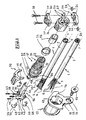
- FIGS. 1, 9A and 10 show the constitution of this optical cable input device.
- junction box 8 composed of a hollow bottom 81 and a cover 82 which close one on the other with conventional interposition of a peripheral seal 10.
- the inlet passage 11 having to have a particular shape, as will be seen below, and this housing being on the other hand a standard housing, there is here provided an adaptation piece 12 which is placed, with interposition of the seal 10 which is locally annular at this location, in the standard inlet port 67 of the housing 8.
- This part 12 advantageously has a side lug 13 pierced with a hole 14 for passage of a screw 15, or a holding pin or other device, which allows to fix it in position on the housing 8.
- This mooring sole 16 is telescopically plugged as shown in the drawing and as will be explained in more detail below, in a tubular sealing body 17, made of plastic material, these two elements 16 and 17 then solidarisant using a locking screw 18.
- This sealing body 17 receives an outer O-ring seal 19, and if its front portion 68 is shaped to receive the mooring flange 16, its rear portion 20 is shaped like a gland, with a thread 21 and support slats 22 which cooperate, conventionally per se, with an annular sealing gasket 23 in fitted relationship with the diameter of the cable 1 and a very special clamping nut 24 of hexagonal outer section, to be clamped on the outer sheath 2 of the cable 1.
- the optical cables can be of different diameters, it is provided, also in adjusted relationship with the diameter of the cable 1 used, a rigid ring compensation 25 which is threaded on the thread 21 and which therefore allows to limit its correct value the tightening of the nut 24, the latter abutting on the ring 25 at the end of clamping stroke.
- the nut 24 also has two longitudinal and lateral tabs 26, 27 which receive, by means of two screws 28 and two associated nuts 29, the two halves 30, 31 of a clamping clamp mechanical cable 1 by clamping this caliper on the outer sheath 2 of this cable.
- a semi-rigid fork shaped key 32 which is intended for locking the device when the latter is mounted on the cable 1 and finally placed in the housing 8.
- the free end 33 of the cable 1 begins by threading successively on this cable very special gland nut 24, the annular seal 23 and the compensation ring 25 if necessary, then the tubular sealing body 17 previously packed with the O-ring 19.
- the piece 17 is made of a plastic material which, while being very rigid, nevertheless retains sufficient flexibility to allow the gland slats 22 to tighten the annular seal 23 when screwing the gland nut 24 (of which, as seen in Figure 10, the inner section is conventionally frustoconical) on its receiving thread 21.
- the plastic used for this is for example an unfilled polyamide.
- the "preparation" of the cable 1 is carried out. For this, it is stripped from the chosen location 34 to leave the desired length of optical fibers 4 free inside the box 8 , its outer sheath 2 and its small protective tubes 3, and the optical fibers 4 thus stripped are stripped.
- the reinforcing tows 5, 6 are cut in such a way that they do not protrude from the transverse stripping plane 34 by a length substantially equal to the length L of the mooring flange 16.
- the metal soleplate 16 is composed (see also FIG. 1) of a single block, of a head 35 which is intended, as will be seen below, to carry out the mooring of the peripheral reinforcements, for example the reinforcements 5 and 6, and the central carrier 7 ( Figure 10) if there is, and a shank 36 in the form of half-cylinder semicircular section.
- This tail 36 will come, as described below, close tightly into the tubular orifice formed at the front half 68 of the sealing body 17.
- the mooring sole 16 is then positioned contiguously with the non-stripped end of the cable 1, that is to say from so that the transverse stripping plane 34 and the transverse plane 37 of the rear end of the tail 36 are substantially merged into one and the same vertical transverse plane in the drawing.
- this head 35 is provided (see in particular FIGS. 1, 4A to 4C) with two lateral notches 38, 39 for lateral introduction of the peripheral reinforcements 6 and 5.
- each of these notches 38, 39 is placed a metal "U" yoke, 40 and 41 respectively, which is slidably mounted from top to bottom, along a vertical guide groove 42 and a vertical orifice of Guiding 43.
- a metal "U" yoke, 40 and 41 respectively, which is slidably mounted from top to bottom, along a vertical guide groove 42 and a vertical orifice of Guiding 43.
- the head 35 is also shaped to moor the possible central carrier 7 (Figure 10).
- the head 35 is pierced, along the median longitudinal axis 48 of the device, of an axial orifice 49, with an oblong section in the vertical direction, which receives and maintains another metal mooring bracket 50 ( Figures 1 and 10).
- the mooring of the central carrier 7 is performed, as before, by wedging the central carrier between the stirrup 50 and the wall of the oblong hole 49 in which the central carrier 7 has been previously introduced, which is also actuated by a vertical tightening screw 51.
- stirrups 40, 41, 50 are not mandatory, and one could be satisfied, as is done for copper son, to block the reinforcing tows 5, 6, and 7 with the help of corresponding screws 44, 45 and 51.
- these calipers are very useful here because they allow to dock securely these reinforcements 5, 6, 7 without injuring them in a way damaging to the reliability of the mooring.
- the front periphery of the sealing body 17 is provided (FIG. 1) with a longitudinal protrusion 52 which is plugged into a longitudinal and conjugate female notch 53 of the head 35 of the metallic soleplate.
- two lateral ribs 65, 66 (FIG. 9A) of the cylindrical internal wall of the body 17 participate in guiding the body 17 when it slides on the tail 36 of the metal soleplate 16.
- the sole 16 and the body 17 are then secured by means of the screw 18 which passes through a vertical orifice 54 of the protrusion 52 and is screwed into a vertical tapping 55 of the head 35 (FIGS. 1 and 10), this tapping. 55 and this orifice 54 then being coaxial.
- hexagonal outer shape, therefore hexagonal, of the nut 24 allows, if desired, to screw it with a wrench.
- the two square nuts 29 are inserted laterally into their respective receiving recesses 56 of the lower stirrup half 31, the two stirrup halves 30, 31 are put in place so that their passage openings 57, 58 two screws 28 coincide with orifices 59, also through which these two screws, which are provided on each of the rear legs 26, 27 of the gland nut 24.
- the two clamping screws 28 are then inserted and screwed into each other. to securely clamp together the nut 24, the stirrup 30, 31 and the cable 1 by its outer sheath 2.
- stirrup 30, 31 is made of a very rigid plastic material, for example Polyamide filled with glass fibers.
- the body 17 and its associated nut 24 are for example polyamide loaded or not, giving them a very slight flexibility, essential to the operation of the gland.
- connection box 8 The assembly is thus thus, according to FIG. 8, completely prepared, moored, and provided with sealing, all this being advantageously carried out outside the connection box 8.
- the following operation consists, according to FIGS. 8 and 9, in introducing this assembly into the box 8, through its inlet passage 11 provided for this purpose, until it reaches a stop in a position (FIG. 9) where only the head 35 of the metal plate 16 and a front groove 60 of the body 17 protrude from the inlet passage 11 towards the inside of the box 8, the inlet seal in this passage 11 being formed by the aforementioned O-ring 19.
- the inlet passage 11 has a particular shape, conjugated for this purpose to that conferred on the body 17, this particular form being, in this embodiment and therefore in no way limiting in itself, conferred by that of the aforementioned adaptation piece 12.
- the inlet passage 11 that is to say here the inner wall of the adapter piece 12
- the O-ring 19 is positioned in an annular groove 64 of the body 17, located here just before the abutment shoulder 63, and, in the stop position according to FIG. 9, this seal 19 is pressed between this groove 64 and the inner wall. passage 11, so the part 12, whose section is, at this location, adjusted accordingly.
- the rear half 70 of the inlet passage 11, that is to say the rear inner surface of the adapter piece 12, has very advantageously a hexagonal shape which is the conjugate female form of the hexagonal outer surface of the In the stop position according to FIG. 9, the nut 24 is at least partially introduced into this hexagonal entry 70 of the passage 11, which blocks it in rotation, so that this input device cable will then effectively withstand the external stresses of torsion that may possibly be exerted later on the cable 1.
- the assembly and implementation of this device is particularly simple and user-friendly, which greatly facilitates the task of the user, and In addition, its longitudinal size inside the chamber or container is significantly reduced.
- the adapter piece 12 could be omitted and simply replaced by a corresponding shape of the inner surface of the inlet passage 11, then made in one piece, typically molding, with the box. 8, as shown schematically in FIG.
Landscapes
- Physics & Mathematics (AREA)
- General Physics & Mathematics (AREA)
- Optics & Photonics (AREA)
- Engineering & Computer Science (AREA)
- Architecture (AREA)
- Civil Engineering (AREA)
- Structural Engineering (AREA)
- Mechanical Coupling Of Light Guides (AREA)
- Light Guides In General And Applications Therefor (AREA)
- Cable Accessories (AREA)
Claims (8)
- Vorrichtung für den dichten Eintritt eines optische Fasern (4) und mindestens eine Verstärkungsschnur (5, 6, 7) aufweisenden Kabels (1) in eine Kammer (8) und durch einen zu diesem Zweck vorgesehenen Eintrittsdurchlass (11), mit:- einem rohrförmigen Dichtkörper (17), der Dichteinrichtungen (19, 21, 22, 23, 24, 25) trägt, welche um den Dichtkörper (17) herum angeordnet sind,- einem Spannelement (30, 31) zum Befestigen des äußeren Mantels (2) des Kabels,- einem Befestigungselement (16), das in bezug auf die Einführrichtung in den Eintrittsdurchlass (11) stromabwärts der Dichteinrichtungen (19, 21, 22, 23, 24, 25) angeordnet und derart ausgebildet ist, dass die Verstärkungsschnur oder -schnüre (5, 6, 7) des Kabels (1) an diesem angebracht und befestigt werden können, bevor dieses in die Kammer (8) eingeführt wird,- wobei eine der Dichteinrichtungen (24) zum Aufnehmen des Spannelements (30, 31) unmittelbar auf dem Dichtkörper (17) in bezug auf die Einführrichtung in den Eintrittsdurchlass (11) stromaufwärts der anderen Dichteinrichtungen (19, 21, 22, 23, 25) ausgebildet ist, und- einer Keilverbindungseinrichtung (32), welche das Verriegeln der Vorrichtung für den dichten Eintritt ermöglicht, wenn diese durch Einsetzen in der Kammer (8) aufgenommen ist.
- Vorrichtung nach Anspruch 1, dadurch gekennzeichnet, dass sie umfasst:- im vorderen Bereich: eine starre Befestigungsklemme (16) mit Öffnungen (49) oder Schlitzen (38, 39) zum Einführen der mittleren (7) und/oder seitlichen (5, 6) Verstärkungsschnüre des Kabels, wobei die Öffnungen oder Schlitze (38, 39, 49) jeweils mit einem üblicherweise durch Drehen einer Schraube (44. 45, 51) wirkenden Klemmelement (40, 41, 50) für die Schnur oder die Schnüre (5, 6, 7), welche es aufnimmt, zusammenwirken,- im hinteren Bereich: eine Mutter (24) zum Klemmen der Stopfbuchse (20), die ferner zum Aufnehmen des Elements (30, 31) zum Spannen des äußeren Mantels (2) des optischen Kabels (1) ausgebildet ist (26, 27),- zwischen dem vorderen und dem hinteren Bereich: den rohrförmigen Dichtkörper (17), dessen vorderer Teil (68) teleskopartig in die Befestigungsklemme (16) eingespannt ist, wobei Einrichtungen (18) zum Verbinden des Dichtkörpers (17) und der Befestigungsklemme (16) in der eingespannten Position vorgesehen sind, und wobei der hintere Teil (20) des rohrförmigen Körpers (17) zusammen mit einem Dichtring (23) die zu der Klemmmutter (24) komplementäre Dichtungsstopfbuchse (21, 22) bildet, welche die Abdichtung durch Klemmung auf den äußeren Mantel (2) des Kabels bewirkt,wobei der Dichtkörper ferner eine Einrichtung (19) zur Abdichtung in bezug auf den Eintrittsdurchlass (11) in die Kammer (8) umfasst, und ferner ein Anschlagelement (63) aufweist, das durch Zusammenwirken mit einer komplementären Ausgestaltung (62) des Eintrittsdurchlasses (11) das Einführen des vorderen Teils der Vorrichtung (16, 17, 24) durch den Eintrittsdurchlass (11) begrenzt, wobei der Anschlag (62, 63) derart positioniert ist, dass der Kopf (35, 60) der Vorrichtung in das Innere der Kammer (8) ragt, wobei zu diesem Zeitpunkt die Keilverbindungseinrichtung (32) vorgesehen wird, um die Vorrichtung in dieser Position zu verriegeln.
- Vorrichtung nach Anspruch 2, dadurch gekennzeichnet, dass die Klemmmutter (24) eine äußere Form mit mehreren Flächen aufweist, während der hintere Teil (70) der Durchlassöffnung (11) die entsprechende weibliche Form aufweist.
- Vorrichtung nach einem der vorhergehenden Ansprüche, dadurch gekennzeichnet, dass die Keilverbindungseinrichtung durch eine halbstarre Spanngabel (32) gebildet ist, die in eine äußere Ringnut (60) der Kabeleingangsvorrichtung eingreift, so dass sie darin teilweise gefangen ist, wobei die Nut (60) infolgedessen in bezug auf den Eintrittsdurchlass (11) stromaufwärts austritt, wenn die Vorrichtung bis zu ihrer Anschlagposition in diesen eingesetzt ist.
- Vorrichtung nach Anspruch 2 oder 3, dadurch gekennzeichnet, dass die Stopfbuchsenmutter (24) zwei hintere Laschen (26, 27) aufweist, die zum Aufnehmen des Spannelements (31, 32) auf dem äußeren Mantel (2) des optischen Kabels (1) ausgebildet sind.
- Vorrichtung nach Anspruch 5, dadurch gekennzeichnet, dass das Spannelement als ein aus zwei Hälften (31, 32) bestehender Bügel ausgebildet ist.
- Vorrichtung nach einem der Ansprüche 2 bis 6, dadurch gekennzeichnet, dass der Dichtkörper (17) einen starren Ausgleichsring (25) aufnimmt, der entsprechend dem Durchmesser des optischen Kabels (1) angepasst ist, um die Klemmung der Stopfbuchsenmutter (24) auf den richtigen Wert zu begrenzen.
- Vorrichtung nach einem der vorhergehenden Ansprüche, dadurch gekennzeichnet, dass die Außenfläche des Dichtkörpers (17) mit einer der Dichteinrichtungen (24) eine Form bildet, welche die der hinteren Innenfläche (70) des Eintrittsdurchlasses (11) entsprechende Form ist, so dass die Vorrichtung gegen Drehen gesichert ist, wenn sie in dem Eintrittsdurchlass (11) aufgenommen ist.
Applications Claiming Priority (2)
| Application Number | Priority Date | Filing Date | Title |
|---|---|---|---|
| FR9810172 | 1998-08-04 | ||
| FR9810172A FR2782172B1 (fr) | 1998-08-04 | 1998-08-04 | Dispositif d'entree de cable a fibres optiques |
Publications (2)
| Publication Number | Publication Date |
|---|---|
| EP0978745A1 EP0978745A1 (de) | 2000-02-09 |
| EP0978745B1 true EP0978745B1 (de) | 2007-10-31 |
Family
ID=9529507
Family Applications (1)
| Application Number | Title | Priority Date | Filing Date |
|---|---|---|---|
| EP99420158A Expired - Lifetime EP0978745B1 (de) | 1998-08-04 | 1999-07-12 | Eingangsstück für ein Faseroptischkabel |
Country Status (19)
| Country | Link |
|---|---|
| US (2) | US6487344B1 (de) |
| EP (1) | EP0978745B1 (de) |
| CN (1) | CN100401122C (de) |
| AR (1) | AR019972A1 (de) |
| AT (1) | ATE377206T1 (de) |
| AU (1) | AU759995B2 (de) |
| BR (1) | BRPI9903376B1 (de) |
| CA (1) | CA2277339C (de) |
| DE (1) | DE69937430T2 (de) |
| DK (1) | DK0978745T3 (de) |
| EG (1) | EG22159A (de) |
| ES (1) | ES2292229T3 (de) |
| FR (1) | FR2782172B1 (de) |
| ID (1) | ID23717A (de) |
| IL (1) | IL131114A (de) |
| MY (1) | MY120256A (de) |
| PL (1) | PL196633B1 (de) |
| TW (1) | TW468072B (de) |
| ZA (1) | ZA994607B (de) |
Families Citing this family (50)
| Publication number | Priority date | Publication date | Assignee | Title |
|---|---|---|---|---|
| US6438300B1 (en) * | 1999-09-21 | 2002-08-20 | Tycom (Us) Inc. | Fiber retaining system |
| TW525789U (en) * | 2001-10-31 | 2003-03-21 | Hon Hai Prec Ind Co Ltd | Fixing apparatus for optical fiber |
| DE10322004B4 (de) * | 2003-05-16 | 2008-09-18 | Hager Electro Gmbh | Vorrichtung zur Befestigung eines Stromkabels |
| DE102004019805B4 (de) * | 2004-04-24 | 2006-08-17 | Telegärtner Gerätebau GmbH | Schutzhülle für Lichtwellenleiterkabel |
| US7268299B2 (en) * | 2004-08-11 | 2007-09-11 | 3M Innovative Properties Company | Telecommunications cable enclosure |
| US7256349B2 (en) * | 2004-08-11 | 2007-08-14 | 3M Innovative Properties Company | Telecommunications cable enclosure |
| US7738759B2 (en) * | 2007-03-16 | 2010-06-15 | 3M Innovative Properties Company | Optical fiber cable inlet device |
| US7711236B2 (en) * | 2007-10-22 | 2010-05-04 | Adc Telecommunications, Inc. | Fiber optic cable clamp |
| CN101910902B (zh) * | 2007-11-19 | 2012-10-03 | 3M创新有限公司 | 通信电缆入口设备 |
| MX2010010708A (es) * | 2008-04-09 | 2010-10-26 | 3M Innovative Properties Co | Dispositivo de entrada de cable de telecomunicaciones. |
| CN101615775A (zh) * | 2008-06-24 | 2009-12-30 | 3M创新有限公司 | 通信线缆引入装置 |
| WO2010014476A2 (en) | 2008-08-01 | 2010-02-04 | 3M Innovative Properties Company | Optical fiber cable inlet device with integral optical device |
| EP2508928B1 (de) | 2008-09-23 | 2015-08-19 | 3M Innovative Properties Company | Gehäuse für Telekommunikationskabel mit entfernbarem Ordnungssystem |
| US8073302B2 (en) * | 2008-12-17 | 2011-12-06 | 3M Innovative Properties Company | Telecommunication enclosure with an interlocking seal |
| MX2011004768A (es) * | 2009-07-16 | 2011-06-01 | Afl Telecommunications Llc | Abrazadera con soporte para retencion de cables. |
| WO2011159639A1 (en) * | 2010-06-15 | 2011-12-22 | Tyco Electronics Corporation | Cable enclosure systems, plugs and methods for using the same |
| CA2804727C (en) * | 2010-07-17 | 2015-11-17 | Harting Electric Gmbh & Co. Kg | Helical cable tension relief |
| WO2012074685A2 (en) * | 2010-11-29 | 2012-06-07 | 3M Innovative Properties Company | Strain relief device |
| RU2597075C2 (ru) | 2012-01-13 | 2016-09-10 | Зм Инновейтив Пропертиз Компани | Коннектор для телекоммуникационных корпусов |
| US11852883B2 (en) * | 2012-04-03 | 2023-12-26 | CommScope Connectivity Belgium BVBA | Cable clamp and telecommunications enclosure |
| US8934751B2 (en) | 2012-11-13 | 2015-01-13 | 3M Innovative Properties Company | Telecommunications cable inlet device |
| US9201205B2 (en) | 2013-01-16 | 2015-12-01 | 3M Innovative Properties Company | Telecommunications cable inlet device |
| WO2015050605A1 (en) | 2013-07-16 | 2015-04-09 | 3M Innovative Properties Company | Strain relief assembly |
| WO2015009435A1 (en) | 2013-07-16 | 2015-01-22 | 3M Innovative Properties Company | Telecommunication enclosure for external connection |
| MX2016000475A (es) | 2013-07-16 | 2016-04-07 | 3M Innovative Properties Co | Conector para cubiertas de telecomunicaciones. |
| US9720198B2 (en) | 2013-07-23 | 2017-08-01 | Panduit Corp. | Strain relief for armored cable |
| US9310568B2 (en) | 2013-11-15 | 2016-04-12 | 3M Innovative Properties Company | Hybrid fiber connector patch cord assemblies |
| GB2532294B (en) * | 2014-11-14 | 2017-11-08 | Coherent Scotland Ltd | Frequency-converted Fiber-MOPA |
| EP3021145B1 (de) * | 2014-11-14 | 2020-04-29 | Corning Optical Communications LLC | Optischer Adapter zur Montage an einem Behälter zum optischen Verbinden anschlussfertiger optischer Kabel |
| JP6210330B2 (ja) * | 2014-12-25 | 2017-10-11 | 株式会社オートネットワーク技術研究所 | 多芯ケーブルのシール構造、及び、シール部材 |
| US9448365B2 (en) | 2014-12-31 | 2016-09-20 | Commscope, Inc. Of North Carolina | Trunk gland adapters and related trunk gland units and methods of connecting trunk cables to fiber optic enclosures |
| US10811862B2 (en) * | 2015-05-21 | 2020-10-20 | CommScope Connectivity Belgium BVBA | Sealable cable port assemblies for telecommunications enclosure |
| ES1151408Y (es) | 2016-01-19 | 2016-05-17 | Giko Group Telecomunicaciones S L | Dispositivo de retención y sellado para cables |
| PL3336992T3 (pl) | 2016-12-14 | 2021-07-26 | Corning Research & Development Corporation | Przepust kablowy |
| EP3396798B1 (de) | 2017-04-25 | 2021-04-07 | Corning Research & Development Corporation | Dichtungskörper für telekommunikationskabel |
| ES2947683T3 (es) | 2017-06-28 | 2023-08-16 | Corning Res And Development Corporation | Conectores de fibra óptica compactos con varios tamaños de conector y conjuntos de cable |
| CN110167303A (zh) * | 2018-01-10 | 2019-08-23 | 重庆三峡学院 | 一种具有防护功能的多路输出同步脉冲控制仪 |
| TWM561954U (zh) * | 2018-01-10 | 2018-06-11 | Amphenol Fiber Optic Technology Shenzhen Co Ltd | 光纖纜線穿設輔助裝置 |
| WO2019231963A1 (en) | 2018-05-30 | 2019-12-05 | Corning Research & Development Corporation | Cable sealing device |
| IT201800005960A1 (it) | 2018-06-01 | 2019-12-01 | Pressacavo | |
| CN109709652A (zh) * | 2019-01-17 | 2019-05-03 | 杭州七友通信科技有限公司 | 光缆接头盒 |
| US11143343B2 (en) * | 2019-05-30 | 2021-10-12 | Bridgeport Fittings, Llc | Adjustable transition coupler |
| CN114072714B (zh) * | 2019-06-26 | 2023-12-05 | 扇港元器件有限公司 | 可现场安装的光纤连接器 |
| US11721932B2 (en) * | 2019-07-09 | 2023-08-08 | Arris Enterprises Llc | Tool-less service cable connector and corresponding systems and methods |
| US11460655B2 (en) | 2020-02-16 | 2022-10-04 | Corning Research & Development Corporation | Cable entry sealing systems for telecommunication enclosures |
| EP4154045A1 (de) * | 2020-05-20 | 2023-03-29 | CommScope Technologies LLC | Aktive optische kabelanordnungen |
| US11604320B2 (en) | 2020-09-30 | 2023-03-14 | Corning Research & Development Corporation | Connector assemblies for telecommunication enclosures |
| US11994722B2 (en) | 2020-11-30 | 2024-05-28 | Corning Research & Development Corporation | Fiber optic adapter assemblies including an adapter housing and a locking housing |
| US11585998B2 (en) | 2021-03-31 | 2023-02-21 | Sterlite Technologies Limited | Optical fibre cable clamping apparatus |
| CH718543A2 (de) * | 2021-04-16 | 2022-10-31 | Agro Ag | Mehrfacheinführung. |
Family Cites Families (19)
| Publication number | Priority date | Publication date | Assignee | Title |
|---|---|---|---|---|
| JPS61267007A (ja) * | 1985-05-21 | 1986-11-26 | Seiko Giken:Kk | 光フアイバコネクタ |
| US4958903A (en) * | 1988-12-09 | 1990-09-25 | At&T Bell Laboratories | Splice closure |
| US5042901A (en) | 1990-07-31 | 1991-08-27 | Siecor Corporation | Preconnectorized optical splice closure |
| US5280556A (en) * | 1992-09-25 | 1994-01-18 | At&T Bell Laboratories | Cable closure which includes a cable sheath gripping assembly |
| CA2160470A1 (en) * | 1993-04-16 | 1994-10-27 | Van Le Huynh | Bonding assembly for fiber optic cable and associated method |
| CN1133644A (zh) * | 1993-09-03 | 1996-10-16 | 雷伊公司 | 光纤连接器 |
| US5425121A (en) | 1994-02-02 | 1995-06-13 | Siecor Corporation | Cable assembly for use with opto-electronic equipment enclosures |
| US5416874A (en) | 1994-07-01 | 1995-05-16 | Siecor Corporation | Optical receiver stub fitting |
| FR2728079B1 (fr) * | 1994-12-08 | 1997-01-10 | Alcatel Cable Interface | Dispositif de maintien d'au moins un cable a fibres optiques et boitier d'epissurage en faisant application |
| FR2729230B1 (fr) * | 1995-01-09 | 1997-03-28 | Crespel Daniel | Dispositif de fixation, de reprise de masse et d'etancheite pour cable optique |
| US5793921A (en) | 1995-03-20 | 1998-08-11 | Psi Telecommunications, Inc. | Kit and method for converting a conductive cable closure to a fiber optic cable closure |
| AU7077996A (en) * | 1995-09-29 | 1997-04-17 | Psi Telecommunications, Inc. | Fiber optic cable splice closure |
| CN2283866Y (zh) * | 1996-01-11 | 1998-06-10 | 姜运平 | 光缆接头盒 |
| DE59703529D1 (de) * | 1996-03-20 | 2001-06-21 | Rxs Ges Fuer Vermoegensverwalt | Kabelmuffe |
| US5745633A (en) | 1996-12-24 | 1998-04-28 | Siecor Corporation | Fiber optic cable assembly for securing a fiber optic cable within an input port of a splice closure |
| US5778122A (en) | 1996-12-24 | 1998-07-07 | Siecor Corporation | Fiber optic cable assembly for interconnecting optical fibers within a receptacle mounted within the wall of an enclosure |
| US5870515A (en) * | 1997-06-06 | 1999-02-09 | Siecor Corporation | Receptacle and associated method for permitting the selective withdrawal of a ferrule |
| FR2782171B1 (fr) * | 1998-08-04 | 2001-11-30 | Pouyet Sa | Dispositif de raccordement de cables a fibres optiques |
| US6028974A (en) * | 1998-08-10 | 2000-02-22 | Alcatel | Seal for underwater cable joint |
-
1998
- 1998-08-04 FR FR9810172A patent/FR2782172B1/fr not_active Expired - Lifetime
-
1999
- 1999-07-07 EG EG81899A patent/EG22159A/xx active
- 1999-07-09 CA CA002277339A patent/CA2277339C/en not_active Expired - Fee Related
- 1999-07-12 AT AT99420158T patent/ATE377206T1/de not_active IP Right Cessation
- 1999-07-12 EP EP99420158A patent/EP0978745B1/de not_active Expired - Lifetime
- 1999-07-12 DE DE69937430T patent/DE69937430T2/de not_active Expired - Lifetime
- 1999-07-12 DK DK99420158T patent/DK0978745T3/da active
- 1999-07-12 ES ES99420158T patent/ES2292229T3/es not_active Expired - Lifetime
- 1999-07-14 AU AU40123/99A patent/AU759995B2/en not_active Ceased
- 1999-07-16 ZA ZA9904607A patent/ZA994607B/xx unknown
- 1999-07-21 MY MYPI99003061A patent/MY120256A/en unknown
- 1999-07-22 ID IDP990695A patent/ID23717A/id unknown
- 1999-07-26 IL IL13111499A patent/IL131114A/en not_active IP Right Cessation
- 1999-07-28 PL PL334666A patent/PL196633B1/pl unknown
- 1999-07-30 AR ARP990103798A patent/AR019972A1/es active IP Right Grant
- 1999-08-02 BR BRPI9903376A patent/BRPI9903376B1/pt not_active IP Right Cessation
- 1999-08-02 US US09/365,622 patent/US6487344B1/en not_active Expired - Lifetime
- 1999-08-03 CN CNB991112466A patent/CN100401122C/zh not_active Expired - Lifetime
- 1999-10-07 TW TW088117287A patent/TW468072B/zh not_active IP Right Cessation
-
2004
- 2004-11-23 US US10/996,326 patent/USRE41743E1/en not_active Expired - Lifetime
Also Published As
| Publication number | Publication date |
|---|---|
| BRPI9903376B1 (pt) | 2016-04-12 |
| AU4012399A (en) | 2000-02-24 |
| DE69937430T2 (de) | 2008-02-21 |
| ES2292229T3 (es) | 2008-03-01 |
| PL334666A1 (en) | 2000-02-14 |
| EG22159A (en) | 2002-09-30 |
| FR2782172A1 (fr) | 2000-02-11 |
| EP0978745A1 (de) | 2000-02-09 |
| CA2277339C (en) | 2009-10-06 |
| DK0978745T3 (da) | 2007-11-26 |
| IL131114A0 (en) | 2001-01-28 |
| ID23717A (id) | 2000-05-11 |
| CA2277339A1 (en) | 2000-02-04 |
| US6487344B1 (en) | 2002-11-26 |
| USRE41743E1 (en) | 2010-09-21 |
| ZA994607B (en) | 1999-08-04 |
| IL131114A (en) | 2002-08-14 |
| ATE377206T1 (de) | 2007-11-15 |
| MY120256A (en) | 2005-09-30 |
| TW468072B (en) | 2001-12-11 |
| PL196633B1 (pl) | 2008-01-31 |
| CN100401122C (zh) | 2008-07-09 |
| AU759995B2 (en) | 2003-05-01 |
| BR9903376A (pt) | 2000-09-19 |
| AR019972A1 (es) | 2002-03-27 |
| CN1248709A (zh) | 2000-03-29 |
| DE69937430D1 (de) | 2007-12-13 |
| FR2782172B1 (fr) | 2001-11-30 |
Similar Documents
| Publication | Publication Date | Title |
|---|---|---|
| EP0978745B1 (de) | Eingangsstück für ein Faseroptischkabel | |
| EP0243234B1 (de) | Bauelement und Verfahren für die Auffächerung der aus einem Kabel für eine Verbindung herausragenden optischen Fasern | |
| EP0439411B1 (de) | Verbundisolator und dessen Herstellungsverfahren | |
| EP0978746A1 (de) | Verbindungsvorrichtung für faseroptische Kabel | |
| FR2763437A1 (fr) | Dispositif d'entree de cable | |
| EP0356329B2 (de) | Abzweigungseinrichtung für die Verbindung eines Nebenkabels an ein durchgehendes Hauptkabel | |
| EP1258666B1 (de) | Schnellkupplung mit Befestigung durch elastischen, äusseren Ring | |
| EP0695900B1 (de) | Dichter Durchgang für Fernmeldekabel | |
| EP0476024B1 (de) | Verbindung für glasfasern | |
| EP2525000B1 (de) | Device for attaching a pipe fitting to a wall | |
| CA2296201C (fr) | Element de connecteur pour fibre optique | |
| EP2112416B1 (de) | Steckanschluss für mindestens ein Rohr | |
| FR2694655A1 (fr) | Dispositif de traversée étanche d'une cloison par des câbles tels que des câbles électriques. | |
| EP0432682B1 (de) | Längswasserdichte Vorrichtung für die Seele eines faseroptischen Kabels | |
| FR2578621A1 (fr) | Dispositif de raccordement amovible pour tuyaux | |
| EP1067324A1 (de) | Schnellkupplung für Verbundrohr mit metallischem Kern | |
| FR2602572A1 (fr) | Dispositif de raccordement d'un tuyau souple autour d'un embout tubulaire rigide | |
| EP2259030B1 (de) | Flüssigkeitszähler, insbesondere für Wasser | |
| EP2998208A1 (de) | Vorrichtung zur befestigung einer schutzummantelung einer hand auf dem griff des lenkers eines motorrads | |
| FR2668240A1 (fr) | Dispositif de raccordement de deux tuyaux de part et d'autre d'un element de cloison. | |
| FR2589210A1 (fr) | Dispositif de fixation d'un culot de maintien sur l'extremite d'un cable | |
| EP1254391A1 (de) | Fixierungsschlauch für faseroptische kabel | |
| FR3048309B1 (fr) | Dispositif de raccordement electrique entre un fil et un element conducteur | |
| WO2022253888A1 (fr) | Réservoir pour gaz sous pression | |
| WO2020079237A1 (fr) | Dispositif de raccordement pour realiser le piquage d'un tube sur une paroi de canalisation |
Legal Events
| Date | Code | Title | Description |
|---|---|---|---|
| PUAI | Public reference made under article 153(3) epc to a published international application that has entered the european phase |
Free format text: ORIGINAL CODE: 0009012 |
|
| AK | Designated contracting states |
Kind code of ref document: A1 Designated state(s): AT BE CH CY DE DK ES FI FR GB GR IE IT LI LU MC NL PT SE |
|
| AX | Request for extension of the european patent |
Free format text: AL;LT;LV;MK;RO;SI |
|
| 17P | Request for examination filed |
Effective date: 20000624 |
|
| AKX | Designation fees paid |
Free format text: AT BE CH CY DE DK ES FI FR GB GR IE IT LI LU MC NL PT SE |
|
| 17Q | First examination report despatched |
Effective date: 20050607 |
|
| REG | Reference to a national code |
Ref country code: HK Ref legal event code: WD Ref document number: 1025388 Country of ref document: HK |
|
| RTI1 | Title (correction) |
Free format text: ENTRY PIECE FOR AN OPTICAL CABLE |
|
| GRAP | Despatch of communication of intention to grant a patent |
Free format text: ORIGINAL CODE: EPIDOSNIGR1 |
|
| GRAS | Grant fee paid |
Free format text: ORIGINAL CODE: EPIDOSNIGR3 |
|
| GRAA | (expected) grant |
Free format text: ORIGINAL CODE: 0009210 |
|
| AK | Designated contracting states |
Kind code of ref document: B1 Designated state(s): AT BE CH CY DE DK ES FI FR GB GR IE IT LI LU MC NL PT SE |
|
| REG | Reference to a national code |
Ref country code: GB Ref legal event code: FG4D Free format text: NOT ENGLISH |
|
| REG | Reference to a national code |
Ref country code: DK Ref legal event code: T3 |
|
| REG | Reference to a national code |
Ref country code: IE Ref legal event code: FG4D Free format text: LANGUAGE OF EP DOCUMENT: FRENCH |
|
| REG | Reference to a national code |
Ref country code: CH Ref legal event code: EP |
|
| REF | Corresponds to: |
Ref document number: 69937430 Country of ref document: DE Date of ref document: 20071213 Kind code of ref document: P |
|
| REG | Reference to a national code |
Ref country code: ES Ref legal event code: FG2A Ref document number: 2292229 Country of ref document: ES Kind code of ref document: T3 |
|
| PG25 | Lapsed in a contracting state [announced via postgrant information from national office to epo] |
Ref country code: SE Free format text: LAPSE BECAUSE OF FAILURE TO SUBMIT A TRANSLATION OF THE DESCRIPTION OR TO PAY THE FEE WITHIN THE PRESCRIBED TIME-LIMIT Effective date: 20080131 |
|
| GBV | Gb: ep patent (uk) treated as always having been void in accordance with gb section 77(7)/1977 [no translation filed] | ||
| PG25 | Lapsed in a contracting state [announced via postgrant information from national office to epo] |
Ref country code: PT Free format text: LAPSE BECAUSE OF FAILURE TO SUBMIT A TRANSLATION OF THE DESCRIPTION OR TO PAY THE FEE WITHIN THE PRESCRIBED TIME-LIMIT Effective date: 20080331 |
|
| REG | Reference to a national code |
Ref country code: IE Ref legal event code: FD4D |
|
| PG25 | Lapsed in a contracting state [announced via postgrant information from national office to epo] |
Ref country code: AT Free format text: LAPSE BECAUSE OF FAILURE TO SUBMIT A TRANSLATION OF THE DESCRIPTION OR TO PAY THE FEE WITHIN THE PRESCRIBED TIME-LIMIT Effective date: 20071031 |
|
| PLBE | No opposition filed within time limit |
Free format text: ORIGINAL CODE: 0009261 |
|
| STAA | Information on the status of an ep patent application or granted ep patent |
Free format text: STATUS: NO OPPOSITION FILED WITHIN TIME LIMIT |
|
| 26N | No opposition filed |
Effective date: 20080801 |
|
| PG25 | Lapsed in a contracting state [announced via postgrant information from national office to epo] |
Ref country code: IE Free format text: LAPSE BECAUSE OF FAILURE TO SUBMIT A TRANSLATION OF THE DESCRIPTION OR TO PAY THE FEE WITHIN THE PRESCRIBED TIME-LIMIT Effective date: 20071031 |
|
| PG25 | Lapsed in a contracting state [announced via postgrant information from national office to epo] |
Ref country code: GB Free format text: LAPSE BECAUSE OF FAILURE TO SUBMIT A TRANSLATION OF THE DESCRIPTION OR TO PAY THE FEE WITHIN THE PRESCRIBED TIME-LIMIT Effective date: 20071031 |
|
| PG25 | Lapsed in a contracting state [announced via postgrant information from national office to epo] |
Ref country code: GR Free format text: LAPSE BECAUSE OF FAILURE TO SUBMIT A TRANSLATION OF THE DESCRIPTION OR TO PAY THE FEE WITHIN THE PRESCRIBED TIME-LIMIT Effective date: 20080201 |
|
| PG25 | Lapsed in a contracting state [announced via postgrant information from national office to epo] |
Ref country code: FI Free format text: LAPSE BECAUSE OF FAILURE TO SUBMIT A TRANSLATION OF THE DESCRIPTION OR TO PAY THE FEE WITHIN THE PRESCRIBED TIME-LIMIT Effective date: 20071031 |
|
| REG | Reference to a national code |
Ref country code: CH Ref legal event code: PL |
|
| PG25 | Lapsed in a contracting state [announced via postgrant information from national office to epo] |
Ref country code: MC Free format text: LAPSE BECAUSE OF NON-PAYMENT OF DUE FEES Effective date: 20080731 |
|
| PG25 | Lapsed in a contracting state [announced via postgrant information from national office to epo] |
Ref country code: LI Free format text: LAPSE BECAUSE OF NON-PAYMENT OF DUE FEES Effective date: 20080731 Ref country code: CH Free format text: LAPSE BECAUSE OF NON-PAYMENT OF DUE FEES Effective date: 20080731 |
|
| PG25 | Lapsed in a contracting state [announced via postgrant information from national office to epo] |
Ref country code: CY Free format text: LAPSE BECAUSE OF FAILURE TO SUBMIT A TRANSLATION OF THE DESCRIPTION OR TO PAY THE FEE WITHIN THE PRESCRIBED TIME-LIMIT Effective date: 20071031 |
|
| PG25 | Lapsed in a contracting state [announced via postgrant information from national office to epo] |
Ref country code: LU Free format text: LAPSE BECAUSE OF NON-PAYMENT OF DUE FEES Effective date: 20080712 |
|
| PGFP | Annual fee paid to national office [announced via postgrant information from national office to epo] |
Ref country code: IT Payment date: 20110719 Year of fee payment: 13 |
|
| PG25 | Lapsed in a contracting state [announced via postgrant information from national office to epo] |
Ref country code: IT Free format text: LAPSE BECAUSE OF NON-PAYMENT OF DUE FEES Effective date: 20120712 |
|
| PGFP | Annual fee paid to national office [announced via postgrant information from national office to epo] |
Ref country code: DK Payment date: 20130711 Year of fee payment: 15 Ref country code: NL Payment date: 20130710 Year of fee payment: 15 |
|
| REG | Reference to a national code |
Ref country code: DK Ref legal event code: EBP Effective date: 20140731 |
|
| REG | Reference to a national code |
Ref country code: NL Ref legal event code: V1 Effective date: 20150201 |
|
| PG25 | Lapsed in a contracting state [announced via postgrant information from national office to epo] |
Ref country code: NL Free format text: LAPSE BECAUSE OF NON-PAYMENT OF DUE FEES Effective date: 20150201 |
|
| PG25 | Lapsed in a contracting state [announced via postgrant information from national office to epo] |
Ref country code: DK Free format text: LAPSE BECAUSE OF NON-PAYMENT OF DUE FEES Effective date: 20140731 |
|
| REG | Reference to a national code |
Ref country code: FR Ref legal event code: PLFP Year of fee payment: 18 |
|
| REG | Reference to a national code |
Ref country code: FR Ref legal event code: PLFP Year of fee payment: 19 |
|
| REG | Reference to a national code |
Ref country code: DE Ref legal event code: R082 Ref document number: 69937430 Country of ref document: DE Representative=s name: EPPING HERMANN FISCHER PATENTANWALTSGESELLSCHA, DE Ref country code: DE Ref legal event code: R082 Ref document number: 69937430 Country of ref document: DE Representative=s name: DOMPATENT VON KREISLER SELTING WERNER - PARTNE, DE Ref country code: DE Ref legal event code: R081 Ref document number: 69937430 Country of ref document: DE Owner name: POUYET 3M TELECOMMUNICATIONS SAS, FR Free format text: FORMER OWNER: POUYET S.A., IVRY SUR SEINE, FR |
|
| REG | Reference to a national code |
Ref country code: DE Ref legal event code: R082 Ref document number: 69937430 Country of ref document: DE Representative=s name: EPPING HERMANN FISCHER PATENTANWALTSGESELLSCHA, DE Ref country code: DE Ref legal event code: R082 Ref document number: 69937430 Country of ref document: DE Representative=s name: DOMPATENT VON KREISLER SELTING WERNER - PARTNE, DE Ref country code: DE Ref legal event code: R081 Ref document number: 69937430 Country of ref document: DE Owner name: POUYET 3M TELECOMMUNICATIONS SAS, FR Free format text: FORMER OWNER: POUYET 3M TELECOMMUNICATIONS SAS, IVRY SUR SEINE, FR |
|
| REG | Reference to a national code |
Ref country code: BE Ref legal event code: HC Owner name: POUYET 3M TELECOMMUNICATIONS SAS; FR Free format text: DETAILS ASSIGNMENT: CHANGE OF OWNER(S), CHANGEMENT DE NOM DU PROPRIETAIRE; FORMER OWNER NAME: POUYET S.A. Effective date: 20171221 |
|
| REG | Reference to a national code |
Ref country code: ES Ref legal event code: PC2A Owner name: POUYET 3M TELECOMMUNICATIONS, SAS Effective date: 20180321 |
|
| REG | Reference to a national code |
Ref country code: FR Ref legal event code: CJ Effective date: 20180320 Ref country code: FR Ref legal event code: CD Owner name: POUYET 3M TELECOMMUNICATIONS, FR Effective date: 20180320 Ref country code: FR Ref legal event code: CA Effective date: 20180320 |
|
| REG | Reference to a national code |
Ref country code: FR Ref legal event code: PLFP Year of fee payment: 20 |
|
| PGFP | Annual fee paid to national office [announced via postgrant information from national office to epo] |
Ref country code: FR Payment date: 20180612 Year of fee payment: 20 |
|
| PGFP | Annual fee paid to national office [announced via postgrant information from national office to epo] |
Ref country code: ES Payment date: 20180801 Year of fee payment: 20 Ref country code: DE Payment date: 20180618 Year of fee payment: 20 |
|
| REG | Reference to a national code |
Ref country code: DE Ref legal event code: R082 Ref document number: 69937430 Country of ref document: DE Representative=s name: EPPING HERMANN FISCHER PATENTANWALTSGESELLSCHA, DE |
|
| PGFP | Annual fee paid to national office [announced via postgrant information from national office to epo] |
Ref country code: BE Payment date: 20180719 Year of fee payment: 20 |
|
| REG | Reference to a national code |
Ref country code: DE Ref legal event code: R071 Ref document number: 69937430 Country of ref document: DE |
|
| REG | Reference to a national code |
Ref country code: BE Ref legal event code: MK Effective date: 20190712 |
|
| REG | Reference to a national code |
Ref country code: ES Ref legal event code: FD2A Effective date: 20201201 |
|
| PG25 | Lapsed in a contracting state [announced via postgrant information from national office to epo] |
Ref country code: ES Free format text: LAPSE BECAUSE OF EXPIRATION OF PROTECTION Effective date: 20190713 |