EP0975492B1 - Airbag - Google Patents
Airbag Download PDFInfo
- Publication number
- EP0975492B1 EP0975492B1 EP98917398A EP98917398A EP0975492B1 EP 0975492 B1 EP0975492 B1 EP 0975492B1 EP 98917398 A EP98917398 A EP 98917398A EP 98917398 A EP98917398 A EP 98917398A EP 0975492 B1 EP0975492 B1 EP 0975492B1
- Authority
- EP
- European Patent Office
- Prior art keywords
- airbag
- fabric
- side impact
- compartment
- folding
- Prior art date
- Legal status (The legal status is an assumption and is not a legal conclusion. Google has not performed a legal analysis and makes no representation as to the accuracy of the status listed.)
- Expired - Lifetime
Links
Images


Classifications
-
- B—PERFORMING OPERATIONS; TRANSPORTING
- B60—VEHICLES IN GENERAL
- B60R—VEHICLES, VEHICLE FITTINGS, OR VEHICLE PARTS, NOT OTHERWISE PROVIDED FOR
- B60R21/00—Arrangements or fittings on vehicles for protecting or preventing injuries to occupants or pedestrians in case of accidents or other traffic risks
- B60R21/02—Occupant safety arrangements or fittings, e.g. crash pads
- B60R21/16—Inflatable occupant restraints or confinements designed to inflate upon impact or impending impact, e.g. air bags
- B60R21/23—Inflatable members
- B60R21/237—Inflatable members characterised by the way they are folded
-
- B—PERFORMING OPERATIONS; TRANSPORTING
- B60—VEHICLES IN GENERAL
- B60R—VEHICLES, VEHICLE FITTINGS, OR VEHICLE PARTS, NOT OTHERWISE PROVIDED FOR
- B60R21/00—Arrangements or fittings on vehicles for protecting or preventing injuries to occupants or pedestrians in case of accidents or other traffic risks
- B60R21/02—Occupant safety arrangements or fittings, e.g. crash pads
- B60R21/16—Inflatable occupant restraints or confinements designed to inflate upon impact or impending impact, e.g. air bags
- B60R21/20—Arrangements for storing inflatable members in their non-use or deflated condition; Arrangement or mounting of air bag modules or components
- B60R21/201—Packaging straps or envelopes for inflatable members
-
- B—PERFORMING OPERATIONS; TRANSPORTING
- B60—VEHICLES IN GENERAL
- B60R—VEHICLES, VEHICLE FITTINGS, OR VEHICLE PARTS, NOT OTHERWISE PROVIDED FOR
- B60R21/00—Arrangements or fittings on vehicles for protecting or preventing injuries to occupants or pedestrians in case of accidents or other traffic risks
- B60R21/02—Occupant safety arrangements or fittings, e.g. crash pads
- B60R21/16—Inflatable occupant restraints or confinements designed to inflate upon impact or impending impact, e.g. air bags
- B60R21/23—Inflatable members
- B60R21/231—Inflatable members characterised by their shape, construction or spatial configuration
- B60R21/23138—Inflatable members characterised by their shape, construction or spatial configuration specially adapted for side protection
-
- B—PERFORMING OPERATIONS; TRANSPORTING
- B60—VEHICLES IN GENERAL
- B60R—VEHICLES, VEHICLE FITTINGS, OR VEHICLE PARTS, NOT OTHERWISE PROVIDED FOR
- B60R21/00—Arrangements or fittings on vehicles for protecting or preventing injuries to occupants or pedestrians in case of accidents or other traffic risks
- B60R21/02—Occupant safety arrangements or fittings, e.g. crash pads
- B60R21/16—Inflatable occupant restraints or confinements designed to inflate upon impact or impending impact, e.g. air bags
- B60R21/23—Inflatable members
- B60R21/231—Inflatable members characterised by their shape, construction or spatial configuration
- B60R21/233—Inflatable members characterised by their shape, construction or spatial configuration comprising a plurality of individual compartments; comprising two or more bag-like members, one within the other
- B60R2021/23324—Inner walls crating separate compartments, e.g. communicating with vents
-
- B—PERFORMING OPERATIONS; TRANSPORTING
- B60—VEHICLES IN GENERAL
- B60R—VEHICLES, VEHICLE FITTINGS, OR VEHICLE PARTS, NOT OTHERWISE PROVIDED FOR
- B60R21/00—Arrangements or fittings on vehicles for protecting or preventing injuries to occupants or pedestrians in case of accidents or other traffic risks
- B60R21/02—Occupant safety arrangements or fittings, e.g. crash pads
- B60R21/16—Inflatable occupant restraints or confinements designed to inflate upon impact or impending impact, e.g. air bags
- B60R21/23—Inflatable members
- B60R21/235—Inflatable members characterised by their material
- B60R2021/23504—Inflatable members characterised by their material characterised by material
- B60R2021/23509—Fabric
-
- B—PERFORMING OPERATIONS; TRANSPORTING
- B60—VEHICLES IN GENERAL
- B60R—VEHICLES, VEHICLE FITTINGS, OR VEHICLE PARTS, NOT OTHERWISE PROVIDED FOR
- B60R21/00—Arrangements or fittings on vehicles for protecting or preventing injuries to occupants or pedestrians in case of accidents or other traffic risks
- B60R21/02—Occupant safety arrangements or fittings, e.g. crash pads
- B60R21/16—Inflatable occupant restraints or confinements designed to inflate upon impact or impending impact, e.g. air bags
- B60R21/23—Inflatable members
- B60R21/231—Inflatable members characterised by their shape, construction or spatial configuration
- B60R21/2334—Expansion control features
- B60R21/2342—Tear seams
Definitions
- the present invention relates to an airbag for a vehicle safety restraint and particularly to a side impact airbag to protect a vehicle occupant from injury in the event of the vehicle sustaining a laterally inflicted impact, and to a method of folding a side impact airbag.
- the object of the present invention is to provide an improved side impact protection device, in particular a side impact airbag and also to provide an improved method of folding the same.
- An object of one aspect of the present invention is to provide an improved side impact airbag which is shaped and mounted so as to inflate at such a speed and in such a direction as to reduce the risk of inflation induced injuries to the vehicle occupant.
- a side impact airbag comprising a first and a second inflatable compartment, the first compartment being adapted and mounted in a vehicle in a position from which it can inflate, on deployment in the event of a crash, to occupy an area generally adjacent to the thorax and the shoulder of a vehicle occupant, and the second inflatable compartment being adapted to inflate, on deployment, to occupy an area generally adjacent to the head of the vehicle occupant, wherein the first and the second compartments are separated one from the other by a dividing panel formed of airbag fabric and are pneumatically connected to each other by means of at least one vent hole formed in the panel, characterised in that fabric of a first weight is used for the lower compartment which protects the thorax and shoulder areas of the vehicle occupant, and the second, upper, compartment of the airbag, which protects the head of the occupant, is formed of fabric of a second, lower, weight.
- the lower compartment has a hole for receiving inflation gas from an inflator in the event of airbag deployment, and the dividing panel is arranged so that it will be in a position approximately at the level of the occupant's shoulder when the airbag is fully inflated.
- the lower compartment may thus be of increased size compared to known dual cavity airbags and this allows the airbag to inflate more quickly past the arm of an occupant and thus for the upper, second compartment to pass the shoulder and thus restrain the head earlier in a crash event.
- Traditional side impact airbags tend to have a problem of interference with an occupant's arm, whereas this invention reduces that problem.
- the airbag is formed of three pieces of fabric stitched together: a first piece forms one side wall of the airbag, a second piece forms a second side wall and a third piece forms the panel dividing the two compartments.
- additional material may be used for one/or more tethers, and/or for reinforcing the gas inlet opening and/or for other strengthening.
- the airbag is arranged and mounted so that as it inflates a rotational force is imparted to the upper, outer region of they airbag (relative to the vehicle occupant) to bias the airbag to move towards the occupant.
- This twisting motion may be imparted by mounting the airbag at an oblique angle to the horizontal, for example at an angle of between 10° and 40° to the horizontal.
- the inflation profile of the airbag and the elongation of it towards the occupant during deployment is further controlled by retaining tethers within one or both inflatable compartments and/or by stitches either joining the side panels of the airbag together, or forming one or more tucks in one or both sides.
- the stitches may be tear stitches which burst at a predetermined pressure as the airbag inflates.
- the tethers may also have tucks in them by means of tear stitches.
- the requirement for strength is not so important in the head bag as in the thorax bag, but it is preferable that the head bag deploys quickly to move past the arm and shoulder before movement of the occupant blocks its deployment path.
- the head bag is preferably formed of a low permeability and a low frictional fabric.
- fabric of 210 denier would be suitable for the upper head compartment and of 630 denier for the lower thorax compartment.
- the low denier fabric has the advantage, for the head compartment, of being of relatively low weight and will therefore move faster on deployment.
- the inflation characteristics of this airbag cushion gives the surprising result that there is less risk to the occupant who is out of position.
- this may advantageously be accomplished by forming the main side panels of the airbag together with the dividing panel from only two pieces of fabric.
- One piece, of a predetermined denier is folded in half and stitched at the sides and the top to form the upper head compartment.
- One or two vent holes are formed in the middle region and this forms the dividing panel.
- the second piece is folded and stitched at the sides, the open top being joined by stitching to the head section on either side of the vent hole or holes.
- the second piece of fabric can be of a different denier.
- 210 denier material may be used for the upper head section and heavier, less permeable 630 denier material for the lower thorax section.
- the lower compartment may be formed first and stitched to the fabric for the upper compartment before the upper compartment is stitched.
- the airbag according to the first aspect of the invention may be mounted in a vehicle door, for example in the door trim or in the padded upholstery.
- the airbag may be mounted in the vehicle seat, either in the upholstery or in the structure of the seat itself.
- a new method of folding a side impact airbag and particularly folding an airbag according to the first aspect aims to overcome many of the disadvantages of the prior art folding methods by producing more consistent unfolding of a side impact airbag during deployment and more reliable positioning of the airbag and of the different compartments of the airbag in relation to the parts of the body of the vehicle occupant to be protected.
- This new folding method comprises laying an uninflated airbag generally flat so that it presents a generally oblong shape in plan view with two opposing minor sides and two opposing major sides, the airbag having a gas inlet opening arranged at or in the region of a first minor side of the shape so formed, subsequently, folding or rolling the upper part of the airbag and folding the folded or rolled part to be on top of the lower part, and, as a first step: folding the two major sides inwardly towards a central major axis, preferably by folding the sides behind and underneath the body of the airbag; as a second step: rolling the minor side remote from the gas inlet opening down towards the gas inlet opening, preferably in a sense opposite to the first folding step (i.e.
- the airbag comprises two interlinked inflatable compartments, adjacent each other along the major sides.
- a first one of the compartments has an inflation opening formed in one side wall and the walls of the second compartment comprise said rolled second minor side, so that the fourth step comprises laying the rolled minor side on the fabric of the first compartment.
- the first compartment is intended for protecting the thorax and shoulder of a vehicle occupant and the second compartment is intended for protecting the head of the vehicle occupant.
- An airbag folded according to the second aspect of the present invention directs the upper head section (second compartment) in a vertically upward direction more quickly than in known systems so that the head section assumes an optimum safety position more quickly and thus generally lessens the risk of entanglement with the occupant's arm. This is particularly useful when the occupant is not sitting in the correct position (for example if he is slewed to the side as may happen if he is asleep) . Since the airbag is primarily accelerated vertically there is a reduced cushion mass accelerating in the horizontal direction (the direction of movement of the vehicle) and this in itself will lessen the effects of impact of the airbag on parts of the occupant's body and thus reduce airbag inflicted injuries.
- An airbag folded according to such a folding method also has a reduced interaction with the vehicle trim as it inflates and thus leads to improved performance of the safety restraint.
- the airbag 10 of Figure 1 is formed from two panels 1 and 2 laid on top of each other and stitched around the periphery at 3.
- a third panel 4 is stitched along its periphery 14 to the middle of each of panels 1 and 2 to form a dividing panel between two compartments 5 and 6 of the airbag.
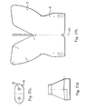
- the shape of the dividing panel 4 is shown more clearly in Figure 2a.
- a inflation inlet hole 11 comprises an H-shaped slit in a reinforcing patch 12 and this inlet hole 11 is preferably set at an angle of between 10° and 40° to the horizontal whereas the mounting is parallel to the horizontal.
- a tether 8 connects the two panels 1 and 2 in the area of the mounting region and the tether shape is shown clearly in Figure 2b.
- the tether is connected to respective panels 1 and 2 along mounting lines 9. Additional tethers 50, 51 are arranged at the narrowest part to help the bag deploy easily in restricted areas (e.g. where the door and seat limit space on each side).
- Tear stitches connect the two panels 1 and 2 at 35 to reduce the initial airbag volume and provide control to the inflation pattern.
- a vent hole 13 is formed in the dividing panel 4 to allow pneumatic communication between the two compartments 5 and 6.
- Two holes may be used optionally joined by a slit or a tear seam either formed by a line of stitches or by a designed structural weakness or by perforations in the vent panel fabric.
- the vent panel 4 may be formed of two pieces sewn together which will separate once the pressure inside the first compartment reaches a predetermined level. This provides a safety venting facility which instantly reduces the inflation speed of the bag in a situation such as when a child is leaning against the airbag deployment direction. In this way a safety vent is provided for dangerous situations while the dual compartment airbag operates normally in other situations inflation gas passing at a controlled rate through the vent hole or holes 13.
- Figure 3 shows the shape in plan view of a suitable cover 15 for the airbag.
- This is typically made of paper and has a generally oblong shape with laterally extending arms 16; two on each long side of the oblong.
- Figure 4 shows the airbag 10 laid flat so that the side panels 1 and 2 overlie each other and the dividing panel 4 is folded in half between the side panels 1 and 2.
- the inflation inlet hole 11 is shown uppermost.
- Figure 5 shows the initial fold lines 17 and 18 and folds are made along these lines to tuck the sides underneath the body of the airbag 10 to form the shape of Figure 6. Then the bag is rolled from the upper end 19 down to the line 20, preferably three times to form the shape of Figure 7.
- the paper cover 15 (see Figure 3) is then attached as shown by lining up the points 22 (which appear as dots in the Figures) on one side of the cover with corresponding points shown on the tether mounting line 9.
- Line 23 provides the next fold line, resulting in the shape of Figure 9 and then a section 24 is folded over to form the shape shown in Figure 10.
- a flap 25 is folded up along fold line 26 as shown in Figure 11 and is subsequently folded down again along line 29 to produce the shape shown in Figure 13.
- the cover 15 is wrapped around the folded airbag so as to effectively encase it in a tube as shown in Figure 14. This is accomplished by folding the bag under along line 31 and folding the cover over along the same line and tucking the upper edge underneath the folded bag.
- the cover may be held in place by spots of adhesive at points 22 and 30.
- the points 22 on one side of the cover 15 are aligned with points 30 on the opposing side of the cover 15 as shown.
- the rolled section of the bag referred to with reference to ( Figure 6) comprise substantially the head section and that this be folded onto the thorax section as shown in Figure 10. In this way, on inflation the head section is directed in a more vertical direction along the side of the vehicle structure providing a faster positioning of the head section into the desired inflated position than was previously possible with known folding methods.
- Figure 17a shows an airbag suitable for mounting in the seat of a vehicle. As with the airbag of Figure 1, it is formed from two panels 1 and 2 stitched around the periphery along line 3. An upper head compartment 5 and a lower thorax compartment 6 are separated by a dividing panel 4 through which a vent hole (not shown) is preferably formed. The alternative areas A, B and C indicated alternative inflation mounting areas. These are always positioned below the dividing panel 4 so as to inflate the thorax compartment 6 before the head compartment 5.
- Figure 17b shows an alternative form for a seat mounted airbag in which the upper head compartment 5 is formed extending at an angle compared to the lower thorax compartment 6. This is formed from a single piece of fabric folded along line 40 and stitched along its periphery.
- the dividing panel 4 is shown in Figure 17c with vent holes 13 formed therein.
- a reinforcing panel for the mounting area 7 is shown in Figure 17d.
- Figures 18 to 25 illustrate a method of folding the seat mounted airbag of Figure 17a or of Figures 17b to d.
- the airbag is laid generally flat as shown in Figure 18.
- the lower left-hand corner is tucked under the airbag as shown in Figure 19.
- the top of the upper compartment 5 is folded down to take the shape shown in Figure 20, i.e. a kite shape.
- Left-hand edges of the kite-shape are then folded in twice as shown in Figure 21.
- the shape is turned through 90° and flattened as indicated by Figure 22.
- the corner D is folded over by about 150mm to form the shape of Figure 23.
- the corner E is folded over by about 85mm to form the shape of Figure 24. This is then folded along line 41 to form generally the compact shape of Figure 25.
- Figures 26 to 31 illustrate an alternative folding method which is nonetheless very similar to the method of Figures 18 to 25.
- the initial steps are identical in that the airbag is laid flat as shown in Figure 26 and the bottom left-hand corner is tucked under as in Figure 27.
- the upper section of the airbag is folded to achieve an elongated hexagon shape 42 in Figure 28.
- the long sides of this elongated hexagon shape are folded over twice towards the middle as indicated by the arrows 43.
- This folded top portion is then folded down and rotated through 90° as shown in Figure 29 so as to achieve the shape of Figure 30.
- This shape is folded along line 43 to achieve the shape of Figure 31 and then the corners F and G are folded over.
- the folded packaging shape is shown in Figure 32 and this is generally the same as the shape shown in Figure 25 which was achieved by the method of Figures 18 to 24.
- Figures 33 to 35 illustrate a method of construction of a dual compartment airbag which has particular advantages.
- This construction method requires only two pieces of fabric.
- One piece of fabric is used for the upper head section 5 and another piece of fabric is used for the lower thorax section 6.
- the piece 5 is folded along centre line 44 and stitched around it periphery at 3.
- the lower section 6 is attached at its outer edges 45 and 46 to lines 47 on the head sections.
- the vent holes 13 are formed in the centre region of the head section 5 and it will be seen that no intermediate panel 4 is required in this method of construction.
- the reinforcing inflation mounting patch is shown at 12 and the inflation inlet at 11.
- the lower section 6 may be attached to the head section 5 first before the sections are stitched to form the compartments.
- the airbag of Figures 33a and b is particularly applicable to a door mounted airbag, whereas a seat mounted airbag is shown in Figures 34a and b.
- the airbag is made from two pieces of fabric 5 and 6, the lower thorax section 6 is shown in Figure 34a and the upper head section 6, again the inflator mounting area is shown at 7 and vent holes at 13.
- FIG 35 schematically illustrates the construction of the airbags of Figures 33a and 33b and 34a and 34b.
- the single airbag of the upper compartment 5 is stitched along its periphery at 3.
- the lower section 6 of fabric is stitched at its open edges to the fabric shown at 5 along stitch lines 3 which are spaced on either side of the vent hole 13.
Landscapes
- Engineering & Computer Science (AREA)
- Mechanical Engineering (AREA)
- Air Bags (AREA)
Description
- The present invention relates to an airbag for a vehicle safety restraint and particularly to a side impact airbag to protect a vehicle occupant from injury in the event of the vehicle sustaining a laterally inflicted impact, and to a method of folding a side impact airbag.
- Side impact airbags are known and are for example described in applicant's own International application published under number WO 96/07563, the subject matter of which is incorporated by reference into the present application. A side impact airbag with two compartments to protect respectively the head and the thorax of an occupant, is also known from
GB 2 229 061. - The object of the present invention is to provide an improved side impact protection device, in particular a side impact airbag and also to provide an improved method of folding the same.
- A problem occurs in side impact airbags in that the occupant's door-side arm tends to interfere with and restrict the correct inflation of the airbag. This can result in injuries to the occupant's arm and/or shoulder.
- An object of one aspect of the present invention is to provide an improved side impact airbag which is shaped and mounted so as to inflate at such a speed and in such a direction as to reduce the risk of inflation induced injuries to the vehicle occupant.
- According to a first aspect of the invention there is provided a side impact airbag comprising a first and a second inflatable compartment, the first compartment being adapted and mounted in a vehicle in a position from which it can inflate, on deployment in the event of a crash, to occupy an area generally adjacent to the thorax and the shoulder of a vehicle occupant, and the second inflatable compartment being adapted to inflate, on deployment, to occupy an area generally adjacent to the head of the vehicle occupant, wherein the first and the second compartments are separated one from the other by a dividing panel formed of airbag fabric and are pneumatically connected to each other by means of at least one vent hole formed in the panel, characterised in that fabric of a first weight is used for the lower compartment which protects the thorax and shoulder areas of the vehicle occupant, and the second, upper, compartment of the airbag, which protects the head of the occupant, is formed of fabric of a second, lower, weight.
- Advantageously the lower compartment has a hole for receiving inflation gas from an inflator in the event of airbag deployment, and the dividing panel is arranged so that it will be in a position approximately at the level of the occupant's shoulder when the airbag is fully inflated.
- The lower compartment may thus be of increased size compared to known dual cavity airbags and this allows the airbag to inflate more quickly past the arm of an occupant and thus for the upper, second compartment to pass the shoulder and thus restrain the head earlier in a crash event. Traditional side impact airbags tend to have a problem of interference with an occupant's arm, whereas this invention reduces that problem.
- According to one embodiment the airbag is formed of three pieces of fabric stitched together: a first piece forms one side wall of the airbag, a second piece forms a second side wall and a third piece forms the panel dividing the two compartments. Of course, additional material may be used for one/or more tethers, and/or for reinforcing the gas inlet opening and/or for other strengthening.
- Preferably the airbag is arranged and mounted so that as it inflates a rotational force is imparted to the upper, outer region of they airbag (relative to the vehicle occupant) to bias the airbag to move towards the occupant. This twisting motion may be imparted by mounting the airbag at an oblique angle to the horizontal, for example at an angle of between 10° and 40° to the horizontal.
- Optionally the inflation profile of the airbag and the elongation of it towards the occupant during deployment is further controlled by retaining tethers within one or both inflatable compartments and/or by stitches either joining the side panels of the airbag together, or forming one or more tucks in one or both sides. The stitches may be tear stitches which burst at a predetermined pressure as the airbag inflates. The tethers may also have tucks in them by means of tear stitches.
- The requirement for strength is not so important in the head bag as in the thorax bag, but it is preferable that the head bag deploys quickly to move past the arm and shoulder before movement of the occupant blocks its deployment path. The head bag is preferably formed of a low permeability and a low frictional fabric. For example fabric of 210 denier would be suitable for the upper head compartment and of 630 denier for the lower thorax compartment. The low denier fabric has the advantage, for the head compartment, of being of relatively low weight and will therefore move faster on deployment. The inflation characteristics of this airbag cushion gives the surprising result that there is less risk to the occupant who is out of position.
- According to another embodiment this may advantageously be accomplished by forming the main side panels of the airbag together with the dividing panel from only two pieces of fabric. One piece, of a predetermined denier is folded in half and stitched at the sides and the top to form the upper head compartment. One or two vent holes are formed in the middle region and this forms the dividing panel. The second piece is folded and stitched at the sides, the open top being joined by stitching to the head section on either side of the vent hole or holes. The second piece of fabric can be of a different denier. For example 210 denier material may be used for the upper head section and heavier, less permeable 630 denier material for the lower thorax section. Of course the lower compartment may be formed first and stitched to the fabric for the upper compartment before the upper compartment is stitched.
- Evidently further fabric pieces may be required for reinforcement, for example in the region of the inflation inlet, and for tethers and such like.
- This arrangement requires less critical sewing lines than with the known arrangements, less pieces of fabric and is thus easier to sew, and produces overall a lighter airbag since a lighter fabric can easily be used for the upper section without prejudicing the performance of the lower compartment. The use of fabrics of different permeabilities also allows for tailoring the damping characteristics as appropriate to the body region to be protected. Previously this was only achievable by coating part of the bag which is expensive.
- The airbag according to the first aspect of the invention may be mounted in a vehicle door, for example in the door trim or in the padded upholstery.
- Alternatively the airbag may be mounted in the vehicle seat, either in the upholstery or in the structure of the seat itself.
- According to a second aspect of the present invention there is provided a new method of folding a side impact airbag and particularly folding an airbag according to the first aspect. This folding method aims to overcome many of the disadvantages of the prior art folding methods by producing more consistent unfolding of a side impact airbag during deployment and more reliable positioning of the airbag and of the different compartments of the airbag in relation to the parts of the body of the vehicle occupant to be protected.
- This new folding method comprises laying an uninflated airbag generally flat so that it presents a generally oblong shape in plan view with two opposing minor sides and two opposing major sides, the airbag having a gas inlet opening arranged at or in the region of a first minor side of the shape so formed, subsequently, folding or rolling the upper part of the airbag and folding the folded or rolled part to be on top of the lower part, and, as a first step: folding the two major sides inwardly towards a central major axis, preferably by folding the sides behind and underneath the body of the airbag; as a second step: rolling the minor side remote from the gas inlet opening down towards the gas inlet opening, preferably in a sense opposite to the first folding step (i.e. forwards and on top of the airbag) preferably rolling the fabric over three times; as a third step: turning the airbag over; as a fourth step: folding the resultant shape so as to bring the rolled second minor side generally parallel to and in close proximity with a generally diagonal line bisecting the resultant shape, in the region of the thorax portion of the airbag; as a fifth step: folding a top corner of the resultant shape over the rolled portion, as a sixth step: folding the sides inwardly on to the top of the rolled portion; and as a seventh step; folding one of the major sides over onto the shape thus formed.
- Preferably the airbag comprises two interlinked inflatable compartments, adjacent each other along the major sides. A first one of the compartments has an inflation opening formed in one side wall and the walls of the second compartment comprise said rolled second minor side, so that the fourth step comprises laying the rolled minor side on the fabric of the first compartment. The first compartment is intended for protecting the thorax and shoulder of a vehicle occupant and the second compartment is intended for protecting the head of the vehicle occupant.
- An airbag folded according to the second aspect of the present invention directs the upper head section (second compartment) in a vertically upward direction more quickly than in known systems so that the head section assumes an optimum safety position more quickly and thus generally lessens the risk of entanglement with the occupant's arm. This is particularly useful when the occupant is not sitting in the correct position (for example if he is slewed to the side as may happen if he is asleep) . Since the airbag is primarily accelerated vertically there is a reduced cushion mass accelerating in the horizontal direction (the direction of movement of the vehicle) and this in itself will lessen the effects of impact of the airbag on parts of the occupant's body and thus reduce airbag inflicted injuries.
- An airbag folded according to such a folding method also has a reduced interaction with the vehicle trim as it inflates and thus leads to improved performance of the safety restraint.
- For a better understanding of the present invention, and to show how the same may be carried into effect reference will now be made, by way of example, to the accompanying drawings, in which:
- Figure 1 is a schematic side view of an airbag according to a first embodiment of the invention, for door mounting;
- Figure 2a illustrates the shape of a dividing panel in the airbag of Figure 1;
- Figure 2b illustrates the shape of a tether used in the airbag of Figure 1;
- Figure 3 illustrates the shape of an airbag cover used to enclose the airbag of Figure 1 when it is folded;
- Figures 4 to 16 illustrate the method of folding the airbag of Figure 1;
- Figures 17a and b illustrate plan views of an airbag according to a second and third embodiment of the invention, for seat mounting;
- Figures 18 to 25 illustrate a method of folding the airbag of Figure 17a or 17b;
- Figures 26 to 32 illustrate an alternative method of folding the airbag of Figure 17a or 17b;
- Figures 33a and b illustrate construction of one embodiment for an airbag according to the first embodiment of the invention;
- Figures 34a and b illustrate the construction of another embodiment of an airbag according to the invention; and
- Figure 35 is a schematic side view of the airbag constructed according to Figures 33 and 34.
-
- The
airbag 10 of Figure 1 is formed from twopanels - A
third panel 4 is stitched along itsperiphery 14 to the middle of each ofpanels compartments panel 4 is shown more clearly in Figure 2a. - The airbag is mounted to the vehicle (door or seat) in the
mounting region 7, for example by mounting pins or rivets. Ainflation inlet hole 11 comprises an H-shaped slit in a reinforcingpatch 12 and thisinlet hole 11 is preferably set at an angle of between 10° and 40° to the horizontal whereas the mounting is parallel to the horizontal. - A tether 8 connects the two
panels respective panels Additional tethers - Tear stitches connect the two
panels - A
vent hole 13 is formed in the dividingpanel 4 to allow pneumatic communication between the twocompartments vent panel 4 may be formed of two pieces sewn together which will separate once the pressure inside the first compartment reaches a predetermined level. This provides a safety venting facility which instantly reduces the inflation speed of the bag in a situation such as when a child is leaning against the airbag deployment direction. In this way a safety vent is provided for dangerous situations while the dual compartment airbag operates normally in other situations inflation gas passing at a controlled rate through the vent hole or holes 13. - The broken lines across the body of the airbag in Figure 1 indicate fold lines for the method of the invention and will be described later in reference to Figures 4 to 16.
- Figure 3 shows the shape in plan view of a
suitable cover 15 for the airbag. This is typically made of paper and has a generally oblong shape with laterally extendingarms 16; two on each long side of the oblong. - A method of folding the airbag of Figures 1 to 3 will now be described.
- Figure 4 shows the
airbag 10 laid flat so that theside panels panel 4 is folded in half between theside panels inflation inlet hole 11 is shown uppermost. - Figure 5 shows the
initial fold lines airbag 10 to form the shape of Figure 6. Then the bag is rolled from theupper end 19 down to theline 20, preferably three times to form the shape of Figure 7. - Subsequently the bag is folded along
line 21, parallel to the major lines of theinflation inlet 11, and parallel to the tether mounting line 9 and this results in the shape of Figure 8. - The paper cover 15 (see Figure 3) is then attached as shown by lining up the points 22 (which appear as dots in the Figures) on one side of the cover with corresponding points shown on the tether mounting line 9.
-
Line 23 provides the next fold line, resulting in the shape of Figure 9 and then asection 24 is folded over to form the shape shown in Figure 10. Aflap 25 is folded up alongfold line 26 as shown in Figure 11 and is subsequently folded down again alongline 29 to produce the shape shown in Figure 13. Thecover 15 is wrapped around the folded airbag so as to effectively encase it in a tube as shown in Figure 14. This is accomplished by folding the bag under alongline 31 and folding the cover over along the same line and tucking the upper edge underneath the folded bag. The cover may be held in place by spots of adhesive atpoints points 22 on one side of thecover 15 are aligned withpoints 30 on the opposing side of thecover 15 as shown. - Subsequently the laterally extending
portions cover arms 16 are folded under to form the folded covered shape of Figure 16. The arms may be attached by spots of adhesive at points 34. - Of course not every step described and/or shown in these Figures is absolutely necessary and some steps may be omitted yet the same effect be achieved. It is however advantageous if the rolled section of the bag referred to with reference to (Figure 6) comprise substantially the head section and that this be folded onto the thorax section as shown in Figure 10. In this way, on inflation the head section is directed in a more vertical direction along the side of the vehicle structure providing a faster positioning of the head section into the desired inflated position than was previously possible with known folding methods.
- This also reduces the interaction of the airbag with the interior trim of the vehicle and tends to reduce inflation induced injuries to the occupant in out-of-position situations since overall less airbag mass is accelerated in the longitudinal direction of the vehicle.
- Figure 17a shows an airbag suitable for mounting in the seat of a vehicle. As with the airbag of Figure 1, it is formed from two
panels line 3. Anupper head compartment 5 and alower thorax compartment 6 are separated by a dividingpanel 4 through which a vent hole (not shown) is preferably formed. The alternative areas A, B and C indicated alternative inflation mounting areas. These are always positioned below the dividingpanel 4 so as to inflate thethorax compartment 6 before thehead compartment 5. - Figure 17b shows an alternative form for a seat mounted airbag in which the
upper head compartment 5 is formed extending at an angle compared to thelower thorax compartment 6. This is formed from a single piece of fabric folded alongline 40 and stitched along its periphery. The dividingpanel 4 is shown in Figure 17c with vent holes 13 formed therein. A reinforcing panel for the mountingarea 7 is shown in Figure 17d. - Figures 18 to 25 illustrate a method of folding the seat mounted airbag of Figure 17a or of Figures 17b to d.
- Firstly the airbag is laid generally flat as shown in Figure 18. Then the lower left-hand corner is tucked under the airbag as shown in Figure 19. Subsequently the top of the
upper compartment 5 is folded down to take the shape shown in Figure 20, i.e. a kite shape. Left-hand edges of the kite-shape are then folded in twice as shown in Figure 21. Then the shape is turned through 90° and flattened as indicated by Figure 22. Then the corner D is folded over by about 150mm to form the shape of Figure 23. Subsequently the corner E is folded over by about 85mm to form the shape of Figure 24. This is then folded alongline 41 to form generally the compact shape of Figure 25. - Figures 26 to 31 illustrate an alternative folding method which is nonetheless very similar to the method of Figures 18 to 25. The initial steps are identical in that the airbag is laid flat as shown in Figure 26 and the bottom left-hand corner is tucked under as in Figure 27. In this case however the upper section of the airbag is folded to achieve an
elongated hexagon shape 42 in Figure 28. The long sides of this elongated hexagon shape are folded over twice towards the middle as indicated by thearrows 43. This folded top portion is then folded down and rotated through 90° as shown in Figure 29 so as to achieve the shape of Figure 30. This shape is folded alongline 43 to achieve the shape of Figure 31 and then the corners F and G are folded over. The folded packaging shape is shown in Figure 32 and this is generally the same as the shape shown in Figure 25 which was achieved by the method of Figures 18 to 24. - Figures 33 to 35 illustrate a method of construction of a dual compartment airbag which has particular advantages. This construction method requires only two pieces of fabric. One piece of fabric is used for the
upper head section 5 and another piece of fabric is used for thelower thorax section 6. Thepiece 5 is folded alongcentre line 44 and stitched around it periphery at 3. Subsequently thelower section 6 is attached at itsouter edges lines 47 on the head sections. The vent holes 13 are formed in the centre region of thehead section 5 and it will be seen that nointermediate panel 4 is required in this method of construction. The reinforcing inflation mounting patch is shown at 12 and the inflation inlet at 11. Of course thelower section 6 may be attached to thehead section 5 first before the sections are stitched to form the compartments. - The airbag of Figures 33a and b is particularly applicable to a door mounted airbag, whereas a seat mounted airbag is shown in Figures 34a and b. As in Figure 33, the airbag is made from two pieces of
fabric lower thorax section 6 is shown in Figure 34a and theupper head section 6, again the inflator mounting area is shown at 7 and vent holes at 13. - Figure 35 schematically illustrates the construction of the airbags of Figures 33a and 33b and 34a and 34b. The single airbag of the
upper compartment 5 is stitched along its periphery at 3. Thelower section 6 of fabric is stitched at its open edges to the fabric shown at 5 alongstitch lines 3 which are spaced on either side of thevent hole 13.
Claims (22)
- A side impact airbag comprising a first (6) and a second (5) inflatable compartment, the first compartment being adapted and mounted in a vehicle in a position from which it can inflate, on deployment in the event of a crash, to occupy an area generally adjacent to the thorax and the shoulder of a vehicle occupant, and the second inflatable compartment (5) being adapted to inflate, on deployment, to occupy an area generally adjacent to the head of the vehicle occupant, wherein the first (6) and the second (5) compartments are separated one from the other by a dividing panel (4) formed of airbag fabric and are pneumatically connected to each other by means of at least one vent hole (13) formed in the panel (4), characterised in that fabric of a first weight is used for the lower compartment (6) which protects the thorax and shoulder areas of the vehicle occupant, and the second, upper, compartment (5) of the airbag, which protects the head of the occupant, is formed of fabric of a second, lower, weight.
- A side impact airbag according to claim 1 wherein the fabric of a first weight is a high strength and high weight fabric.
- A side impact airbag according to any one of claims 1 and 2 wherein the upper compartment (5) is formed of a low permeability and a low frictional fabric.
- A side impact airbag according to claim 3 wherein said low permeability and low frictional fabric is fabric of 210 denier and the other fabric is of 630 denier.
- A side impact airbag according to any one of the preceding claims wherein the dividing panel (4) is arranged to be in a position approximately at the level of the occupant's shoulder when the airbag is fully inflated.
- A side impact airbag according to any one of the preceding claims wherein the lower compartment (6) has a hole for receiving inflation gas from an inflator in the event of airbag deployment.
- A side impact airbag according to any preceding claim wherein the airbag is formed of three pieces of fabric stitched together such that: a first piece forms one side wall (1) of the airbag, a second piece forms a second side wall (2) and a third piece forms the panel (4) dividing the two compartments.
- A side impact airbag according to claim 7 wherein additional material is used for one or more tethers (8), and/or for reinforcing the gas inlet opening and/or for other strengthening of the airbag.
- A side impact airbag according to any preceding claim wherein the airbag is arranged and mounted so that as it inflates a rotational force is imparted to the upper, outer region of the airbag, relative to the vehicle occupant to bias the airbag to move towards the occupant.
- A side impact airbag according to claim 9 wherein the airbag is mounted at an oblique angle to the horizontal.
- A side impact airbag according to claim 10 wherein said angle is between 10° and 40° to the horizontal.
- A side impact airbag according to any preceding claim wherein the inflation profile of the airbag and the elongation of it towards the occupant during deployment is further controlled by retaining tethers (50, 51) within one or both inflatable compartments.
- A side impact airbag according to any preceding claim wherein stitches are provided joining the side panels (1, 2) of the airbag together.
- A side impact airbag according to any preceding claim wherein the inflation profile of the airbag and the elongation of it towards the occupant during deployment is further controlled by stitches (35) forming one or more tucks in one or both side panels (1, 2).
- A side impact airbag according to claim 13 or 14 wherein the stitches are arranged to burst at a predetermined pressure as the airbag inflates.
- A side impact airbag according to any preceding claim wherein the two side panels and the dividing panel (4) are all formed from two pieces of fabric.
- A side impact airbag according to claim 16 comprising a first piece of fabric of a predetermined denier, folded in half and stitched at the sides and the top to form the upper, head, compartment (5), one or two vent holes (13) formed in the middle region which forms the dividing panel (4), and a second piece of fabric of a different denier folded and stitched at the sides, the open top being joined by stitching to the upper, head, compartment on each side of the vent hole or holes (13).
- A side impact airbag according to claim 17 wherein fabric pieces are used for reinforcement.
- A side impact airbag according to any preceding claim mounted in a vehicle door.
- A side impact airbag according to claim 19 when mounted in the vehicle door trim.
- A side impact airbag according to any one of claims 1 to 18 wherein the airbag is mounted in the vehicle seat, either in the upholstery or in the structure of the seat itself.
- A method of folding an airbag comprising laying an uninflated airbag generally flat so that it presents a generally oblong shape in plan view with two opposing minor sides and two opposing major sides, the airbag having a gas inlet opening (11) arranged at or in the region of a first minor side of the shape so formed, subsequently, folding or rolling the upper part of the airbag and folding the folded or rolled part to be on top of the lower part, and comprising as a first step: folding the two major sides inwardly towards a central major axis, preferably by folding the sides behind and underneath the body of the airbag; as a second step: rolling the minor side remote from the gas inlet opening down towards the gas inlet opening, preferably in a sense opposite to the first folding step (i.e. forwards and on top of the airbag) preferably rolling the fabric over three times; as a third step: turning the airbag over; as a fourth step: folding the resultant shape so as to bring the rolled second minor side generally parallel to and in close proximity with a generally diagonal line bisecting the resultant shape, in the region of the thorax portion of the airbag; as a fifth step: folding a top corner of the resultant shape over the rolled portion, as a sixth step: folding the sides inwardly on to the top of the rolled portion; and as a seventh step; folding one of the major sides over onto the shape thus formed, wherein the airbag comprises two interlinked inflatable compartments (5, 6), adjacent each other along the major sides and a first one of the compartments has an inflation opening (11) formed in one side wall and the walls of the second compartment comprise said rolled second minor side, so that the fourth step comprises laying the rolled minor side on the fabric of the first compartment.
Applications Claiming Priority (3)
| Application Number | Priority Date | Filing Date | Title |
|---|---|---|---|
| GB9707857A GB2324280A (en) | 1997-04-18 | 1997-04-18 | A side impact airbag and a method of folding an airbag |
| GB9707857 | 1997-04-18 | ||
| PCT/GB1998/001130 WO1998047744A1 (en) | 1997-04-18 | 1998-04-17 | Airbag |
Publications (2)
| Publication Number | Publication Date |
|---|---|
| EP0975492A1 EP0975492A1 (en) | 2000-02-02 |
| EP0975492B1 true EP0975492B1 (en) | 2002-01-02 |
Family
ID=10810974
Family Applications (1)
| Application Number | Title | Priority Date | Filing Date |
|---|---|---|---|
| EP98917398A Expired - Lifetime EP0975492B1 (en) | 1997-04-18 | 1998-04-17 | Airbag |
Country Status (5)
| Country | Link |
|---|---|
| US (1) | US6213500B1 (en) |
| EP (1) | EP0975492B1 (en) |
| DE (1) | DE69803370T2 (en) |
| GB (1) | GB2324280A (en) |
| WO (1) | WO1998047744A1 (en) |
Families Citing this family (22)
| Publication number | Priority date | Publication date | Assignee | Title |
|---|---|---|---|---|
| US6371518B1 (en) * | 2000-02-23 | 2002-04-16 | Breed Automotive Technology, Inc. | Air bag, module and method of folding a side air bag or cushion |
| US6962363B2 (en) * | 2000-07-07 | 2005-11-08 | Milliken & Company | Multiple chamber airbags and methods |
| EP1698523A3 (en) * | 2000-08-30 | 2008-04-02 | Milliken & Company | Abrasion and/or puncture resistant fabrics, airbag cushions, and methods |
| US20020122908A1 (en) | 2000-08-30 | 2002-09-05 | Shulong Li | Abrasion and/or puncture resistant fabrics, airbag cushions, and methods |
| US6508486B1 (en) * | 2001-06-06 | 2003-01-21 | Delphi Technologies, Inc. | Door mounted side restraint |
| US20030222446A1 (en) * | 2002-05-30 | 2003-12-04 | Quin Soderquist | Inflator insertion apparatus and method for airbag systems |
| US6942242B2 (en) * | 2002-06-25 | 2005-09-13 | Delphi Technologies, Inc. | Biasing deployment flap and inflatable cushion cover |
| US7223224B2 (en) * | 2003-01-27 | 2007-05-29 | Tk Holdings Inc. | Airbag folding method |
| US7063350B2 (en) * | 2003-09-23 | 2006-06-20 | Autoliv Asp, Inc. | Dual chamber side airbag apparatus and method |
| US20050134032A1 (en) * | 2003-12-17 | 2005-06-23 | Downing Drew G. | Airbag folding method |
| US7059630B2 (en) * | 2004-03-31 | 2006-06-13 | Tk Holdings, Inc. | Head side airbag cushion fold |
| US20060012155A1 (en) * | 2004-07-01 | 2006-01-19 | Ford Global Technologies, Llc | Vehicle side airbag apparatus and seat containing same |
| US7448645B2 (en) * | 2006-03-31 | 2008-11-11 | Ford Global Technologies, Llc | Contoured side impact airbag |
| JP4434193B2 (en) * | 2006-10-30 | 2010-03-17 | トヨタ自動車株式会社 | Side airbag device for vehicle |
| US7278656B1 (en) * | 2007-01-30 | 2007-10-09 | Key Safety Systems, Inc. | Seat mounted side impact airbag module |
| KR100803624B1 (en) | 2007-06-12 | 2008-02-19 | 델파이코리아 주식회사 | Side airbag |
| JP5081532B2 (en) * | 2007-08-09 | 2012-11-28 | タカタ株式会社 | Side airbag device |
| DE102008036403A1 (en) * | 2008-08-01 | 2010-04-01 | Takata-Petri Ag | airbag |
| US9272683B2 (en) * | 2013-03-14 | 2016-03-01 | Tk Holdings Inc. | Dual chambered passenger airbag |
| KR102505747B1 (en) * | 2018-08-07 | 2023-03-03 | 현대모비스 주식회사 | Folding method of far-side airbag |
| US10994687B2 (en) * | 2018-12-11 | 2021-05-04 | Autoliv Asp, Inc. | Airbag compression wrappers and related airbag assemblies |
| CN109774646B (en) * | 2019-03-13 | 2023-09-01 | 上海临港均胜汽车安全系统有限公司 | Overhead type air bag |
Family Cites Families (16)
| Publication number | Priority date | Publication date | Assignee | Title |
|---|---|---|---|---|
| US3642303A (en) * | 1970-02-13 | 1972-02-15 | Gen Motors Corp | Vehicle occupant restraint system |
| US3752501A (en) * | 1971-10-20 | 1973-08-14 | Ford Motor Co | Steering wheel inflatable cushion device |
| AU654090B2 (en) * | 1992-10-16 | 1994-10-20 | Morton International, Inc. | Multi-chamber passenger air bag cushion with interchamber venting |
| JP3456754B2 (en) * | 1994-06-14 | 2003-10-14 | 本田技研工業株式会社 | How to deploy vehicle airbags |
| WO1996007563A1 (en) | 1994-09-08 | 1996-03-14 | Alliedsignal Deutschland Gmbh | Inflatable safety restraint for vehicle occupant protection |
| US5556128A (en) * | 1994-11-24 | 1996-09-17 | Volkswagen Ag | Safety arrangement for a vehicle occupant |
| DE4443027A1 (en) * | 1994-12-02 | 1996-06-05 | Trw Repa Gmbh | Side impact gas bag |
| GB2299061B (en) * | 1995-03-23 | 1998-09-30 | Autoliv Dev | Improvements in or relating to a safety arrangement |
| US5586782A (en) * | 1995-06-26 | 1996-12-24 | Alliedsignal Inc. | Dual pressure side impact air bag |
| US5730464A (en) * | 1995-08-11 | 1998-03-24 | General Motors Corporation | Air bag module with tether |
| DE19538657A1 (en) * | 1995-10-17 | 1997-04-24 | Trw Repa Gmbh | Airbag side impact protection device |
| US5718450A (en) * | 1996-01-19 | 1998-02-17 | Takata, Inc. | Inflatable restraint system having a head/thorax cushion for side impact protection |
| US5848804A (en) * | 1996-05-29 | 1998-12-15 | Trw Vehicle Safety Systems Inc. | Side impact air bag module |
| GB2317370B (en) * | 1996-09-21 | 1998-12-02 | Breed Automotive Tech | Apparatus for protecting a vehicle occupant |
| JP3430835B2 (en) * | 1996-09-26 | 2003-07-28 | 三菱自動車工業株式会社 | Air bag device |
| US5791685A (en) * | 1997-02-20 | 1998-08-11 | Alliedsignal Inc. | Three-chambered side impact air bag |
-
1997
- 1997-04-18 GB GB9707857A patent/GB2324280A/en not_active Withdrawn
-
1998
- 1998-04-17 EP EP98917398A patent/EP0975492B1/en not_active Expired - Lifetime
- 1998-04-17 US US09/403,159 patent/US6213500B1/en not_active Expired - Lifetime
- 1998-04-17 DE DE69803370T patent/DE69803370T2/en not_active Expired - Lifetime
- 1998-04-17 WO PCT/GB1998/001130 patent/WO1998047744A1/en active IP Right Grant
Also Published As
| Publication number | Publication date |
|---|---|
| DE69803370D1 (en) | 2002-02-28 |
| DE69803370T2 (en) | 2002-08-14 |
| US6213500B1 (en) | 2001-04-10 |
| EP0975492A1 (en) | 2000-02-02 |
| GB9707857D0 (en) | 1997-06-04 |
| GB2324280A (en) | 1998-10-21 |
| WO1998047744A1 (en) | 1998-10-29 |
Similar Documents
| Publication | Publication Date | Title |
|---|---|---|
| EP0975492B1 (en) | Airbag | |
| US8328229B2 (en) | Airbag module | |
| EP0710194B1 (en) | Air bag with inflation limiter | |
| JP3577208B2 (en) | Passenger airbag device | |
| JP3781292B2 (en) | Side airbag for vehicle and folding method thereof | |
| JP6064876B2 (en) | Side airbag device | |
| US5454595A (en) | Hidden volume cushion | |
| US5378019A (en) | Controlled deployment driver's side air bag | |
| US5290061A (en) | Folded air bag | |
| EP1577172B1 (en) | Airbag device | |
| US20090091111A1 (en) | Air bag with deployment flap | |
| JP2000289559A (en) | Airbag | |
| JP2004512209A (en) | Multi-chamber airbag and method | |
| KR20130045058A (en) | Knee airbag for vehicel and folding method thereof | |
| EP1636072B1 (en) | An air-bag | |
| KR100494985B1 (en) | A side air bag for automobile | |
| KR100493723B1 (en) | A side air bag for automobile | |
| JP2009107577A (en) | Airbag and airbag device | |
| JP5171707B2 (en) | Airbag device | |
| JPH07125587A (en) | Air bag | |
| CN117984936A (en) | Far-end air bag, far-end air bag device and air bag sewing method | |
| KR20220017164A (en) | Side airbag apparatus and manufacturing method thereof | |
| WO2004078534A1 (en) | An air-bag | |
| GB2317369A (en) | Method of folding an airbag | |
| WO1995006574A1 (en) | Air bag with improved tear stitch pattern |
Legal Events
| Date | Code | Title | Description |
|---|---|---|---|
| PUAI | Public reference made under article 153(3) epc to a published international application that has entered the european phase |
Free format text: ORIGINAL CODE: 0009012 |
|
| 17P | Request for examination filed |
Effective date: 19991029 |
|
| AK | Designated contracting states |
Kind code of ref document: A1 Designated state(s): DE FR GB IT |
|
| GRAG | Despatch of communication of intention to grant |
Free format text: ORIGINAL CODE: EPIDOS AGRA |
|
| GRAG | Despatch of communication of intention to grant |
Free format text: ORIGINAL CODE: EPIDOS AGRA |
|
| 17Q | First examination report despatched |
Effective date: 20010326 |
|
| GRAG | Despatch of communication of intention to grant |
Free format text: ORIGINAL CODE: EPIDOS AGRA |
|
| GRAH | Despatch of communication of intention to grant a patent |
Free format text: ORIGINAL CODE: EPIDOS IGRA |
|
| GRAH | Despatch of communication of intention to grant a patent |
Free format text: ORIGINAL CODE: EPIDOS IGRA |
|
| GRAA | (expected) grant |
Free format text: ORIGINAL CODE: 0009210 |
|
| REG | Reference to a national code |
Ref country code: GB Ref legal event code: IF02 |
|
| AK | Designated contracting states |
Kind code of ref document: B1 Designated state(s): DE FR GB IT |
|
| REF | Corresponds to: |
Ref document number: 69803370 Country of ref document: DE Date of ref document: 20020228 |
|
| ET | Fr: translation filed | ||
| PLBE | No opposition filed within time limit |
Free format text: ORIGINAL CODE: 0009261 |
|
| STAA | Information on the status of an ep patent application or granted ep patent |
Free format text: STATUS: NO OPPOSITION FILED WITHIN TIME LIMIT |
|
| 26N | No opposition filed | ||
| REG | Reference to a national code |
Ref country code: GB Ref legal event code: 732E |
|
| REG | Reference to a national code |
Ref country code: FR Ref legal event code: TP |
|
| PGFP | Annual fee paid to national office [announced via postgrant information from national office to epo] |
Ref country code: GB Payment date: 20090312 Year of fee payment: 12 |
|
| PGFP | Annual fee paid to national office [announced via postgrant information from national office to epo] |
Ref country code: IT Payment date: 20090418 Year of fee payment: 12 Ref country code: FR Payment date: 20090406 Year of fee payment: 12 |
|
| GBPC | Gb: european patent ceased through non-payment of renewal fee |
Effective date: 20100417 |
|
| REG | Reference to a national code |
Ref country code: FR Ref legal event code: ST Effective date: 20101230 |
|
| PG25 | Lapsed in a contracting state [announced via postgrant information from national office to epo] |
Ref country code: IT Free format text: LAPSE BECAUSE OF NON-PAYMENT OF DUE FEES Effective date: 20100417 Ref country code: GB Free format text: LAPSE BECAUSE OF NON-PAYMENT OF DUE FEES Effective date: 20100417 |
|
| PG25 | Lapsed in a contracting state [announced via postgrant information from national office to epo] |
Ref country code: FR Free format text: LAPSE BECAUSE OF NON-PAYMENT OF DUE FEES Effective date: 20100430 |
|
| PGFP | Annual fee paid to national office [announced via postgrant information from national office to epo] |
Ref country code: DE Payment date: 20170428 Year of fee payment: 20 |
|
| REG | Reference to a national code |
Ref country code: DE Ref legal event code: R071 Ref document number: 69803370 Country of ref document: DE |