EP0920363B1 - A method of producing a cutting tool insert - Google Patents
A method of producing a cutting tool insert Download PDFInfo
- Publication number
- EP0920363B1 EP0920363B1 EP97934787A EP97934787A EP0920363B1 EP 0920363 B1 EP0920363 B1 EP 0920363B1 EP 97934787 A EP97934787 A EP 97934787A EP 97934787 A EP97934787 A EP 97934787A EP 0920363 B1 EP0920363 B1 EP 0920363B1
- Authority
- EP
- European Patent Office
- Prior art keywords
- cutting edge
- ion beam
- cutting
- diamond
- produced
- Prior art date
- Legal status (The legal status is an assumption and is not a legal conclusion. Google has not performed a legal analysis and makes no representation as to the accuracy of the status listed.)
- Expired - Lifetime
Links
- 238000005520 cutting process Methods 0.000 title claims abstract description 64
- 238000000034 method Methods 0.000 title claims abstract description 23
- 239000010432 diamond Substances 0.000 claims abstract description 28
- 229910003460 diamond Inorganic materials 0.000 claims abstract description 27
- 239000000463 material Substances 0.000 claims abstract description 20
- 238000010849 ion bombardment Methods 0.000 claims abstract description 12
- 238000003698 laser cutting Methods 0.000 claims abstract description 6
- 238000010884 ion-beam technique Methods 0.000 claims description 28
- XKRFYHLGVUSROY-UHFFFAOYSA-N Argon Chemical compound [Ar] XKRFYHLGVUSROY-UHFFFAOYSA-N 0.000 claims description 6
- 229910052786 argon Inorganic materials 0.000 claims description 3
- 230000001419 dependent effect Effects 0.000 claims description 2
- 239000007789 gas Substances 0.000 claims description 2
- 238000005530 etching Methods 0.000 description 6
- 238000009499 grossing Methods 0.000 description 5
- 238000005229 chemical vapour deposition Methods 0.000 description 4
- 238000004519 manufacturing process Methods 0.000 description 3
- 230000010355 oscillation Effects 0.000 description 3
- 238000005498 polishing Methods 0.000 description 3
- 230000000694 effects Effects 0.000 description 2
- 229910000831 Steel Inorganic materials 0.000 description 1
- 238000007796 conventional method Methods 0.000 description 1
- 239000013078 crystal Substances 0.000 description 1
- 230000007547 defect Effects 0.000 description 1
- 238000003801 milling Methods 0.000 description 1
- 238000007517 polishing process Methods 0.000 description 1
- 238000000992 sputter etching Methods 0.000 description 1
- 239000010959 steel Substances 0.000 description 1
- 238000001308 synthesis method Methods 0.000 description 1
- 230000000930 thermomechanical effect Effects 0.000 description 1
Images

Classifications
-
- B—PERFORMING OPERATIONS; TRANSPORTING
- B23—MACHINE TOOLS; METAL-WORKING NOT OTHERWISE PROVIDED FOR
- B23P—METAL-WORKING NOT OTHERWISE PROVIDED FOR; COMBINED OPERATIONS; UNIVERSAL MACHINE TOOLS
- B23P15/00—Making specific metal objects by operations not covered by a single other subclass or a group in this subclass
- B23P15/28—Making specific metal objects by operations not covered by a single other subclass or a group in this subclass cutting tools
- B23P15/40—Making specific metal objects by operations not covered by a single other subclass or a group in this subclass cutting tools shearing tools
-
- A—HUMAN NECESSITIES
- A61—MEDICAL OR VETERINARY SCIENCE; HYGIENE
- A61F—FILTERS IMPLANTABLE INTO BLOOD VESSELS; PROSTHESES; DEVICES PROVIDING PATENCY TO, OR PREVENTING COLLAPSING OF, TUBULAR STRUCTURES OF THE BODY, e.g. STENTS; ORTHOPAEDIC, NURSING OR CONTRACEPTIVE DEVICES; FOMENTATION; TREATMENT OR PROTECTION OF EYES OR EARS; BANDAGES, DRESSINGS OR ABSORBENT PADS; FIRST-AID KITS
- A61F9/00—Methods or devices for treatment of the eyes; Devices for putting in contact-lenses; Devices to correct squinting; Apparatus to guide the blind; Protective devices for the eyes, carried on the body or in the hand
- A61F9/007—Methods or devices for eye surgery
- A61F9/013—Instruments for compensation of ocular refraction ; Instruments for use in cornea removal, for reshaping or performing incisions in the cornea
Definitions
- This invention relates to a method of producing cutting tool inserts such as surgical blades made from single crystal or polycrystalline diamond.
- a method of producing or cutting edge comprising the features of the preamble of claim 1 is known from ZA-A-9307997.
- Diamond has successfully been used since the early 1970's as the ultimate material for surgical scalpels, in particular, for use in eye operations (ophthalmology). Its hardness, strength and perfect crystalline nature allow the manufacture of cutting edges that are defect free under microscopic examination at for instance 100 x magnification, as required for ophthalmology. Surgical instruments equipped with diamond scalpels outperform steel scalpels by lowering cutting resistance and creating less deformation of the tissue being cut thus allowing better precision in the operation. This is particularly important as some operations require operating precision down to 1/100 of a millimeter or better.
- polycrystalline diamond Although the basic properties of polycrystalline diamond make it suitable for use in surgical scalpels, the conventional methods for working monocrystalline diamond are not suitable when applied to polycrystalline material. For example, the time needed to polish a single facet on a monocrystalline scalpel is of the order of minutes. Using the same method on polycrystalline material many hours are required thus losing the cost advantage of the material. In addition, the resulting cutting edge will fail to reach the quality required as it is extremely difficult to avoid chipping the cutting edge during the polishing process.
- a practical method to shape diamond products known in the diamond industry is to laser cut the material, usually with a Nd-YAG laser beam.
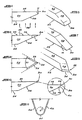
- This method produces a typical profile as represented in Figure 1. Referring to this figure, it can be seen that at the laser beam 10 entry side, the material edge 12 is rounded producing what is called a shoulder.
- this shoulder is a disadvantage.
- a method of producing a cutting edge on a layer of ultra-hard material includes the steps of providing a plate of the material, which plate has major flat surfaces on opposite sides thereof, laser cutting the plate transverse to the major surfaces to produce two or more layers each having a cutting edge defined on a surface produced by the laser cut and exposing the cutting edge to an ion bombardment etch (also known as ion beam milling).
- the cutting edge is typically defined between the surface produced by the laser cut and a major surface of the plate.
- the method includes the step of ion beam smoothing the other surface or one or both of the major surfaces of the plate prior to or after the laser cutting. It has been found that ion beam smoothing reduces the friction during cutting and can lead to an improved initial cutting edge being produced by the laser cut.
- the cutting edge which is produced may be a single faceted or multifaceted cutting edge. Alternatively, two or more such cutting edges may be provided.
- the cutting edge or edges may be straight or curved, or a combination thereof.
- the cutting edge may be non-symmetric or symmetric.
- Non-symmetric cutting edges in the context of blades are those in which one of the two intersecting surfaces forming the cutting edge is a surface of the blade itself.
- Symmetric cutting edges in the context of blades are edges in which neither of the two intersecting surfaces forming the cutting edge is a surface of the blade itself.
- the invention has application to producing cutting blades for cutting tools and, more particularly, for diamond cutting tools.
- the diamond may be single crystalline or polycrystalline in nature, although the invention has greatest application with diamond which is polycrystalline in nature.
- the diamond may be natural, but is preferably produced synthetically, and more particularly by chemical vapour deposition (CVD).
- the laser beam which is used to effect the laser cut may be any known in the art, typically a Nd-YAG beam.
- the ion bombardment etch is achieved using an ion beam. preferably neutralised, with argon as the preferable gas source.
- the ion bombardment will etch away the material at a rate which depends on the nature of the material. In the case of diamond, the rate will be approximately 0,05 to 10 ⁇ m per hour. It has been found that the etch rate is a function of the angle of incidence.
- the maximum etch rate has been measured at a 54 degree incident angle, as can be seen from the graph illustrated by Figure 3. The maximum etch rate will typically occur around 54 degrees but this angle ( ⁇ ) is dependent on the condition of the etch.
- Suitable ion bombardment etch conditions using argon are a voltage of 250 to 1500 volts to accelerate the ion beam and a current density of between 0,2 mA/cm 2 and 20 mA/cm 2 , these conditions being maintained for a time suitable to remove a layer of thickness between 1 and 50 ⁇ m from a surface of the material.
- Conditions similar to the ion bombardment etch may be used for ion beam smoothing one or more of the surfaces of the plate or layer.
- the incident angle of the ion beam will typically be about 0 degrees (normal to the surface) and may be stationary or oscillating.
- the invention is capable of producing very fine cutting edges and ones which have an apex radius of less than 50nm. and preferably less than 20nm.
- the method of the invention may be used to produce a high quality, sharp cutting edge for a cutting tool insert, particularly a surgical blade. Further, the invention can also be used to improve the surface quality of a surface or facet which leads to a cutting edge. This has particular importance for surgical blades as it reduces the t p value (this is an accepted standard measure for the smoothness of a surface) of such a surface thereby reducing the blade's resistance during tissue cutting.
- a polycrystalline CVD diamond plate is cut into two, producing two layers of polycrystalline CVD diamond as illustrated by Figure 1 or Figure 2. Edges of the layers, e.g. edges 12 or 16. may thereafter be subjected to an ion beam etch to produce a sharp cutting edge. It is preferred that the major flat surfaces of the plates, indicated as D1 and D2 (if not polished), are ion beam smoothed prior to the laser cut being effected.
- a diamond cutting blade 20 has opposed flat longitudinal surfaces 22, 24 and a transverse surface 26 created by a laser cut.
- the ion beam preferably a neutralised ion beam, is directed at the cutting tool in the direction of the arrows 28, i.e. normal to the surface 24. This, as mentioned, produces an included angle ( ⁇ ), at the cutting edge 30.
- This angle is independent of the initial cross section and thus the method of the invention eliminates the laser cut shoulder and edge radius as is found in prior art laser cuts (see Figure 1). It is possible to reduce the included angle resulting from the ion beam etch by appropriately tilting the ion beam and choosing an angle of incidence greater than 0 degrees, for example, 10 degrees. Further, the method of the invention can also be applied effectively on multifaceted products, by rotating the product during the etching process.
- a cutting edge with no waviness can be achieved by polishing a microflat on to a laser shaped cutting edge and thereafter polishing a microfacet on to the now blunt edge.
- This embodiment is illustrated by Figure 10 where parts similar to those of Figures 4 and 5 carry like numerals.
- the surface 26 produced by the laser cut may be polished to create a microflat 38 and thereafter a microfacet 40 is polished on to the now blunt edge.
- This polishing can be mechanical or thermomechanical. As the amount of material being removed is very small, this can be done relatively quickly.
- the blade is then sharpened by ion beam etching, as described above in relation to the embodiment of Figures 4 and 5, to remove the remnants of the small facet 40, as shown by the dotted line 42. This gives a very sharp, smooth cutting edge.
- the cutting edge is identified as 44. However, since the removal of material at 38 and 40 is so small, the ion beam etching effectively sharpens the cutting edge 30 defined between the laser cut surface 26 and the surface 22.
- the invention is capable of producing very fine cutting edges and ones which have an apex radius of less than 50nm, and preferably less than 20nm. For all cutting edges, no matter how fine, there will be an apex radius. This apex radius is "r" shown in Figure 11.
- the cutting edge is 44 and the surfaces leading to the cutting edge are 46, 48.
Landscapes
- Engineering & Computer Science (AREA)
- Mechanical Engineering (AREA)
- Laser Beam Processing (AREA)
- Turning (AREA)
- Crystals, And After-Treatments Of Crystals (AREA)
- Surgical Instruments (AREA)
- Scissors And Nippers (AREA)
Abstract
Description
Claims (8)
- A method of producing a cutting edge (30) on a layer (20) of diamond includes the steps of providing a diamond plate, which plate has major flat surfaces (D1, D2) on opposite sides thereof, laser cutting the plate transverse to the major surfaces (D1, D2) to produce two or more layers (20), each having a cutting edge (30) defined between the transverse surface (26) produced by the laser cut and one of the major surfaces (D1, D2), wherein a first major surface (22) and the transverse surface (26) include a sharp angle, characterized by exposing the cutting edge (30) to an ion bombardment etch, wherein said ion beam is tiltable, such that the angle of incidence between the ion beam and the normal on a second major surface (24) will be varied between 0° to 90° minus said sharp angle, in a quadrant formed by said second major surface (24) and the normal thereof, said quadrant being remote from the cutting edge (30), dependent on the shape of the cutting edge to be produced, or wherein the ion beam is directed to said first major surface (22) such that the angle of incidence is generally greater than 50° in a quadrant remote from said cutting edge (30).
- A method according to claim 1 wherein one or both of the major surfaces (D1, D2) of the plate are ion beam smoothed prior to the laser cutting step.
- A method according to any one of the preceding claims wherein the ion beam for the ion bombardment etch is a neutralised ion beam.
- A method according to any of the preceding claims wherein the gas source for the ion beam of the ion bombardment etch is argon.
- A method according to claim 4 wherein the ion bombardment etch conditions are a voltage of 250 to 1500 volts to accelerate the ion beam and a current density of between 0,2mA/cm2 and 20mA/cm2, these conditions being maintained for a time suitable to remove a layer of thickness between 1 and 50 microns from the surface of the material.
- A method according to any one of the preceding claims wherein the ion bombardment etch removes material at a rate of 0.05 to 10µm per hour.
- A method according to any one of the preceding claims wherein the cutting edge produced has an apex radius less than 50 nm.
- A method according to claims 1 to 6 wherein the cutting edge produced has an apex radius of less than 20 nm.
Applications Claiming Priority (3)
| Application Number | Priority Date | Filing Date | Title |
|---|---|---|---|
| ZA9606459 | 1996-07-30 | ||
| ZA966459 | 1996-07-30 | ||
| PCT/NL1997/000448 WO1998004382A1 (en) | 1996-07-30 | 1997-07-30 | A method of producing a cutting tool insert |
Publications (2)
| Publication Number | Publication Date |
|---|---|
| EP0920363A1 EP0920363A1 (en) | 1999-06-09 |
| EP0920363B1 true EP0920363B1 (en) | 2002-12-04 |
Family
ID=25585815
Family Applications (1)
| Application Number | Title | Priority Date | Filing Date |
|---|---|---|---|
| EP97934787A Expired - Lifetime EP0920363B1 (en) | 1996-07-30 | 1997-07-30 | A method of producing a cutting tool insert |
Country Status (7)
| Country | Link |
|---|---|
| US (1) | US6353204B1 (en) |
| EP (1) | EP0920363B1 (en) |
| JP (1) | JP2000515818A (en) |
| AT (1) | ATE228914T1 (en) |
| AU (1) | AU3786997A (en) |
| DE (1) | DE69717635T2 (en) |
| WO (1) | WO1998004382A1 (en) |
Families Citing this family (43)
| Publication number | Priority date | Publication date | Assignee | Title |
|---|---|---|---|---|
| DE19859905C2 (en) | 1998-01-27 | 2002-05-23 | Gfd Ges Fuer Diamantprodukte M | Diamond cutting tool |
| US6615496B1 (en) * | 2000-05-04 | 2003-09-09 | Sandia Corporation | Micromachined cutting blade formed from {211}-oriented silicon |
| DE10112286C1 (en) * | 2001-03-14 | 2002-08-29 | Brasseler Gmbh & Co Kg Geb | Method of making a surgical saw blade |
| US20050028389A1 (en) * | 2001-06-12 | 2005-02-10 | Wort Christopher John Howard | Cvd diamond cutting insert |
| US7140812B2 (en) * | 2002-05-29 | 2006-11-28 | 3M Innovative Properties Company | Diamond tool with a multi-tipped diamond |
| GB0212530D0 (en) * | 2002-05-30 | 2002-07-10 | Diamanx Products Ltd | Diamond cutting insert |
| US20040186493A1 (en) * | 2003-03-17 | 2004-09-23 | Mcwhorter Paul Jackson | Microkeratome cutting head assembly with single bevel cutting blade |
| US20040181950A1 (en) * | 2003-03-17 | 2004-09-23 | Rodgers Murray Steven | Alignment of microkeratome blade to blade handle |
| US20040181928A1 (en) * | 2003-03-17 | 2004-09-23 | Smith Norman Frank | Mounting a blade handle on a microkeratome blade |
| US20040186494A1 (en) * | 2003-03-17 | 2004-09-23 | Mcwhorter Paul Jackson | Microkeratome cutting head assembly with reduced contact between cutting blade and eye flap |
| US6993818B2 (en) * | 2003-03-17 | 2006-02-07 | Memx, Inc. | Multi-fixture assembly of cutting tools |
| US20040204726A1 (en) * | 2003-03-17 | 2004-10-14 | Memx, Inc. | Separating a microkeratome blade from a wafer |
| GB0317854D0 (en) * | 2003-07-30 | 2003-09-03 | Element Six Ltd | Method of manufacturing diamond substrates |
| US20060144821A1 (en) * | 2005-01-04 | 2006-07-06 | Academia Sinica | Method for engraving irreproducible pattern on the surface of a diamond |
| US8709219B2 (en) * | 2005-03-10 | 2014-04-29 | Panasonic Corporation | Structured diamond tool made by focused ion beam nanomachining |
| TWI410538B (en) * | 2005-11-15 | 2013-10-01 | Carnegie Inst Of Washington | New diamond uses/applications based on single-crystal cvd diamond produced at rapid growth rate |
| US7448135B2 (en) * | 2006-03-29 | 2008-11-11 | The Gillette Company | Multi-blade razors |
| US7882640B2 (en) * | 2006-03-29 | 2011-02-08 | The Gillette Company | Razor blades and razors |
| US20070227008A1 (en) * | 2006-03-29 | 2007-10-04 | Andrew Zhuk | Razors |
| US8011104B2 (en) | 2006-04-10 | 2011-09-06 | The Gillette Company | Cutting members for shaving razors |
| US8499462B2 (en) | 2006-04-10 | 2013-08-06 | The Gillette Company | Cutting members for shaving razors |
| KR101830969B1 (en) * | 2007-10-16 | 2018-02-21 | 쓰리엠 이노베이티브 프로퍼티즈 컴파니 | Higher transmission light control film |
| WO2009061766A2 (en) * | 2007-11-05 | 2009-05-14 | Baker Hughes Incorporated | Methods and apparatuses for forming cutting elements having a chamfered edge for earth-boring tools |
| US10016876B2 (en) | 2007-11-05 | 2018-07-10 | Baker Hughes, A Ge Company, Llc | Methods of forming polycrystalline compacts and earth-boring tools including polycrystalline compacts |
| KR101546554B1 (en) * | 2007-12-21 | 2015-08-25 | 쓰리엠 이노베이티브 프로퍼티즈 컴파니 | Light control film |
| US9248579B2 (en) * | 2008-07-16 | 2016-02-02 | The Gillette Company | Razors and razor cartridges |
| WO2010148082A2 (en) | 2009-06-18 | 2010-12-23 | 3M Innovative Properties Company | Light control film |
| US9463531B2 (en) | 2009-10-23 | 2016-10-11 | Kennametal Inc. | Three-dimensional surface shaping of rotary cutting tool edges with lasers |
| JP4976576B2 (en) * | 2010-11-01 | 2012-07-18 | 住友電気工業株式会社 | Cutting tool, manufacturing method thereof and manufacturing apparatus |
| EP2495081B1 (en) | 2011-03-01 | 2014-05-07 | GFD Gesellschaft für Diamantprodukte mbH | Cutting tool with blade made from fine-crystalline diamond |
| EP2495080B1 (en) | 2011-03-01 | 2014-05-21 | GFD Gesellschaft für Diamantprodukte mbH | Cutting tool with blade made from fine-crystalline diamond |
| JP5878086B2 (en) | 2012-06-21 | 2016-03-08 | 住友電工ハードメタル株式会社 | Cutting tool manufacturing method |
| JP5956855B2 (en) * | 2012-07-04 | 2016-07-27 | 日本航空電子工業株式会社 | Cutting edge processing method and tool manufacturing method |
| DE102014207507B4 (en) | 2014-04-17 | 2021-12-16 | Kennametal Inc. | Cutting tool and method for producing a cutting tool |
| DE102014207510B4 (en) | 2014-04-17 | 2021-12-16 | Kennametal Inc. | Cutting tool and method for producing a cutting tool |
| US20150374402A1 (en) * | 2014-06-26 | 2015-12-31 | University Of Utah Research Foundation | Surgical blade |
| US9643282B2 (en) | 2014-10-17 | 2017-05-09 | Kennametal Inc. | Micro end mill and method of manufacturing same |
| EP3327179B1 (en) | 2015-07-22 | 2023-08-23 | Sumitomo Electric Industries, Ltd. | Single crystal diamond material, single crystal diamond tip, and drilling tool |
| US9931714B2 (en) | 2015-09-11 | 2018-04-03 | Baker Hughes, A Ge Company, Llc | Methods and systems for removing interstitial material from superabrasive materials of cutting elements using energy beams |
| WO2020021501A1 (en) * | 2018-07-27 | 2020-01-30 | Ecole Polytechnique Federale De Lausanne (Epfl) | Non-contact polishing of a crystalline layer or substrate by ion beam etching |
| CA3143929A1 (en) * | 2019-06-25 | 2020-12-30 | Howard L. Shackelford | Retractable surgical blade device and method |
| CN111185942B (en) * | 2020-02-25 | 2023-10-27 | 深圳市誉和光学精密刀具有限公司 | Cutter and processing method thereof |
| US12168281B2 (en) | 2022-01-11 | 2024-12-17 | Baker Hughes Oilfield Operations Llc | Polycrystalline diamond compact cutting elements, methods of forming same and earth-boring tools |
Family Cites Families (11)
| Publication number | Priority date | Publication date | Assignee | Title |
|---|---|---|---|---|
| GB1544130A (en) * | 1977-06-28 | 1979-04-11 | Gillette Co | Formation of sharp cutting edges |
| IE48798B1 (en) * | 1978-08-18 | 1985-05-15 | De Beers Ind Diamond | Method of making tool inserts,wire-drawing die blank and drill bit comprising such inserts |
| GB8821944D0 (en) * | 1988-09-19 | 1988-10-19 | Gillette Co | Method & apparatus for forming surface of workpiece |
| JPH03138546A (en) * | 1989-10-25 | 1991-06-12 | Sumitomo Electric Ind Ltd | Diamond microtome knife and its manufacture |
| US5178645A (en) * | 1990-10-08 | 1993-01-12 | Sumitomo Electric Industries, Ltd. | Cutting tool of polycrystalline diamond and method of manufacturing the same |
| JPH05180736A (en) * | 1991-12-27 | 1993-07-23 | Sumitomo Electric Ind Ltd | Manufacturing method of diamond knife for microtome |
| ZA937997B (en) * | 1992-10-26 | 1994-06-13 | De Beers Ind Diamond | A method of producing a tool insert |
| US5347887A (en) * | 1993-03-11 | 1994-09-20 | Microsurgical Techniques, Inc. | Composite cutting edge |
| US5447208A (en) * | 1993-11-22 | 1995-09-05 | Baker Hughes Incorporated | Superhard cutting element having reduced surface roughness and method of modifying |
| ZA958166B (en) | 1994-10-04 | 1996-04-24 | Drukker Int Bv | Cutting tool |
| US5643523A (en) * | 1995-04-18 | 1997-07-01 | Saint-Gobain/Norton Industrial Ceramics Corp. | Method of manufacturing diamond-coated cutting tool inserts |
-
1997
- 1997-07-30 EP EP97934787A patent/EP0920363B1/en not_active Expired - Lifetime
- 1997-07-30 AT AT97934787T patent/ATE228914T1/en not_active IP Right Cessation
- 1997-07-30 DE DE69717635T patent/DE69717635T2/en not_active Expired - Fee Related
- 1997-07-30 JP JP10508721A patent/JP2000515818A/en active Pending
- 1997-07-30 US US09/230,606 patent/US6353204B1/en not_active Expired - Fee Related
- 1997-07-30 WO PCT/NL1997/000448 patent/WO1998004382A1/en active IP Right Grant
- 1997-07-30 AU AU37869/97A patent/AU3786997A/en not_active Abandoned
Also Published As
| Publication number | Publication date |
|---|---|
| ATE228914T1 (en) | 2002-12-15 |
| DE69717635D1 (en) | 2003-01-16 |
| US6353204B1 (en) | 2002-03-05 |
| WO1998004382A1 (en) | 1998-02-05 |
| AU3786997A (en) | 1998-02-20 |
| EP0920363A1 (en) | 1999-06-09 |
| JP2000515818A (en) | 2000-11-28 |
| DE69717635T2 (en) | 2003-04-10 |
Similar Documents
| Publication | Publication Date | Title |
|---|---|---|
| EP0920363B1 (en) | A method of producing a cutting tool insert | |
| CA1243588A (en) | Cutting implement and method of making same | |
| AU782041B2 (en) | Atomically sharp edged cutting blades and methods for making same | |
| US4653373A (en) | Knife blade and method for making same | |
| EP1397234B1 (en) | Cvd diamond cutting insert | |
| JP5956855B2 (en) | Cutting edge processing method and tool manufacturing method | |
| US5048191A (en) | Razor blade technology | |
| US5121660A (en) | Razor blade technology | |
| EP0476087A1 (en) | Razor blade technology | |
| EP2813304B1 (en) | Edge tool | |
| WO2019065949A1 (en) | Diamond-coated rotation cutting tool | |
| US5667344A (en) | CVD diamond cutting tools with oriented crystal grain boundaries | |
| JP5568649B1 (en) | Cutlery tool | |
| EP0720887A1 (en) | Cutting tool | |
| JPH06194593A (en) | Production of polygon mirror | |
| CZ20003600A3 (en) | Atomically sharp edged cutting blades and methods for making same | |
| MXPA00010076A (en) | Atomically sharp edged cutting blades and methods for making same | |
| JPH029505A (en) | Cutting tool made from ultra hard brittle material |
Legal Events
| Date | Code | Title | Description |
|---|---|---|---|
| PUAI | Public reference made under article 153(3) epc to a published international application that has entered the european phase |
Free format text: ORIGINAL CODE: 0009012 |
|
| 17P | Request for examination filed |
Effective date: 19990202 |
|
| AK | Designated contracting states |
Kind code of ref document: A1 Designated state(s): AT CH DE FR GB IT LI NL SE |
|
| 17Q | First examination report despatched |
Effective date: 19990615 |
|
| GRAG | Despatch of communication of intention to grant |
Free format text: ORIGINAL CODE: EPIDOS AGRA |
|
| GRAG | Despatch of communication of intention to grant |
Free format text: ORIGINAL CODE: EPIDOS AGRA |
|
| GRAH | Despatch of communication of intention to grant a patent |
Free format text: ORIGINAL CODE: EPIDOS IGRA |
|
| GRAH | Despatch of communication of intention to grant a patent |
Free format text: ORIGINAL CODE: EPIDOS IGRA |
|
| GRAA | (expected) grant |
Free format text: ORIGINAL CODE: 0009210 |
|
| AK | Designated contracting states |
Kind code of ref document: B1 Designated state(s): AT CH DE FR GB IT LI NL SE |
|
| PG25 | Lapsed in a contracting state [announced via postgrant information from national office to epo] |
Ref country code: IT Free format text: LAPSE BECAUSE OF FAILURE TO SUBMIT A TRANSLATION OF THE DESCRIPTION OR TO PAY THE FEE WITHIN THE PRESCRIBED TIME-LIMIT;WARNING: LAPSES OF ITALIAN PATENTS WITH EFFECTIVE DATE BEFORE 2007 MAY HAVE OCCURRED AT ANY TIME BEFORE 2007. THE CORRECT EFFECTIVE DATE MAY BE DIFFERENT FROM THE ONE RECORDED. Effective date: 20021204 Ref country code: AT Free format text: LAPSE BECAUSE OF FAILURE TO SUBMIT A TRANSLATION OF THE DESCRIPTION OR TO PAY THE FEE WITHIN THE PRESCRIBED TIME-LIMIT Effective date: 20021204 |
|
| REF | Corresponds to: |
Ref document number: 228914 Country of ref document: AT Date of ref document: 20021215 Kind code of ref document: T |
|
| REG | Reference to a national code |
Ref country code: GB Ref legal event code: FG4D |
|
| REG | Reference to a national code |
Ref country code: CH Ref legal event code: NV Representative=s name: BOVARD AG PATENTANWAELTE Ref country code: CH Ref legal event code: EP |
|
| REF | Corresponds to: |
Ref document number: 69717635 Country of ref document: DE Date of ref document: 20030116 |
|
| PG25 | Lapsed in a contracting state [announced via postgrant information from national office to epo] |
Ref country code: SE Free format text: LAPSE BECAUSE OF FAILURE TO SUBMIT A TRANSLATION OF THE DESCRIPTION OR TO PAY THE FEE WITHIN THE PRESCRIBED TIME-LIMIT Effective date: 20030304 |
|
| ET | Fr: translation filed | ||
| PLBE | No opposition filed within time limit |
Free format text: ORIGINAL CODE: 0009261 |
|
| STAA | Information on the status of an ep patent application or granted ep patent |
Free format text: STATUS: NO OPPOSITION FILED WITHIN TIME LIMIT |
|
| 26N | No opposition filed |
Effective date: 20030905 |
|
| PGFP | Annual fee paid to national office [announced via postgrant information from national office to epo] |
Ref country code: DE Payment date: 20080814 Year of fee payment: 12 Ref country code: CH Payment date: 20080815 Year of fee payment: 12 |
|
| PGFP | Annual fee paid to national office [announced via postgrant information from national office to epo] |
Ref country code: NL Payment date: 20080703 Year of fee payment: 12 Ref country code: FR Payment date: 20080718 Year of fee payment: 12 |
|
| PGFP | Annual fee paid to national office [announced via postgrant information from national office to epo] |
Ref country code: GB Payment date: 20080806 Year of fee payment: 12 |
|
| REG | Reference to a national code |
Ref country code: CH Ref legal event code: PL |
|
| GBPC | Gb: european patent ceased through non-payment of renewal fee |
Effective date: 20090730 |
|
| NLV4 | Nl: lapsed or anulled due to non-payment of the annual fee |
Effective date: 20100201 |
|
| REG | Reference to a national code |
Ref country code: FR Ref legal event code: ST Effective date: 20100331 |
|
| PG25 | Lapsed in a contracting state [announced via postgrant information from national office to epo] |
Ref country code: LI Free format text: LAPSE BECAUSE OF NON-PAYMENT OF DUE FEES Effective date: 20090731 Ref country code: FR Free format text: LAPSE BECAUSE OF NON-PAYMENT OF DUE FEES Effective date: 20090731 Ref country code: CH Free format text: LAPSE BECAUSE OF NON-PAYMENT OF DUE FEES Effective date: 20090731 |
|
| PG25 | Lapsed in a contracting state [announced via postgrant information from national office to epo] |
Ref country code: GB Free format text: LAPSE BECAUSE OF NON-PAYMENT OF DUE FEES Effective date: 20090730 |
|
| PG25 | Lapsed in a contracting state [announced via postgrant information from national office to epo] |
Ref country code: DE Free format text: LAPSE BECAUSE OF NON-PAYMENT OF DUE FEES Effective date: 20100202 |
|
| PG25 | Lapsed in a contracting state [announced via postgrant information from national office to epo] |
Ref country code: NL Free format text: LAPSE BECAUSE OF NON-PAYMENT OF DUE FEES Effective date: 20100201 |