EP0801506A2 - A method and apparatus for suppressing blocking artifacts in block-transform coded images - Google Patents
A method and apparatus for suppressing blocking artifacts in block-transform coded images Download PDFInfo
- Publication number
- EP0801506A2 EP0801506A2 EP97200913A EP97200913A EP0801506A2 EP 0801506 A2 EP0801506 A2 EP 0801506A2 EP 97200913 A EP97200913 A EP 97200913A EP 97200913 A EP97200913 A EP 97200913A EP 0801506 A2 EP0801506 A2 EP 0801506A2
- Authority
- EP
- European Patent Office
- Prior art keywords
- block
- values
- coefficient
- blocks
- image
- Prior art date
- Legal status (The legal status is an assumption and is not a legal conclusion. Google has not performed a legal analysis and makes no representation as to the accuracy of the status listed.)
- Withdrawn
Links
Images


Classifications
-
- H—ELECTRICITY
- H04—ELECTRIC COMMUNICATION TECHNIQUE
- H04N—PICTORIAL COMMUNICATION, e.g. TELEVISION
- H04N19/00—Methods or arrangements for coding, decoding, compressing or decompressing digital video signals
- H04N19/85—Methods or arrangements for coding, decoding, compressing or decompressing digital video signals using pre-processing or post-processing specially adapted for video compression
- H04N19/86—Methods or arrangements for coding, decoding, compressing or decompressing digital video signals using pre-processing or post-processing specially adapted for video compression involving reduction of coding artifacts, e.g. of blockiness
-
- H—ELECTRICITY
- H04—ELECTRIC COMMUNICATION TECHNIQUE
- H04N—PICTORIAL COMMUNICATION, e.g. TELEVISION
- H04N19/00—Methods or arrangements for coding, decoding, compressing or decompressing digital video signals
- H04N19/10—Methods or arrangements for coding, decoding, compressing or decompressing digital video signals using adaptive coding
- H04N19/102—Methods or arrangements for coding, decoding, compressing or decompressing digital video signals using adaptive coding characterised by the element, parameter or selection affected or controlled by the adaptive coding
- H04N19/117—Filters, e.g. for pre-processing or post-processing
-
- H—ELECTRICITY
- H04—ELECTRIC COMMUNICATION TECHNIQUE
- H04N—PICTORIAL COMMUNICATION, e.g. TELEVISION
- H04N19/00—Methods or arrangements for coding, decoding, compressing or decompressing digital video signals
- H04N19/10—Methods or arrangements for coding, decoding, compressing or decompressing digital video signals using adaptive coding
- H04N19/134—Methods or arrangements for coding, decoding, compressing or decompressing digital video signals using adaptive coding characterised by the element, parameter or criterion affecting or controlling the adaptive coding
- H04N19/136—Incoming video signal characteristics or properties
- H04N19/14—Coding unit complexity, e.g. amount of activity or edge presence estimation
-
- H—ELECTRICITY
- H04—ELECTRIC COMMUNICATION TECHNIQUE
- H04N—PICTORIAL COMMUNICATION, e.g. TELEVISION
- H04N19/00—Methods or arrangements for coding, decoding, compressing or decompressing digital video signals
- H04N19/10—Methods or arrangements for coding, decoding, compressing or decompressing digital video signals using adaptive coding
- H04N19/134—Methods or arrangements for coding, decoding, compressing or decompressing digital video signals using adaptive coding characterised by the element, parameter or criterion affecting or controlling the adaptive coding
- H04N19/146—Data rate or code amount at the encoder output
- H04N19/149—Data rate or code amount at the encoder output by estimating the code amount by means of a model, e.g. mathematical model or statistical model
-
- H—ELECTRICITY
- H04—ELECTRIC COMMUNICATION TECHNIQUE
- H04N—PICTORIAL COMMUNICATION, e.g. TELEVISION
- H04N19/00—Methods or arrangements for coding, decoding, compressing or decompressing digital video signals
- H04N19/10—Methods or arrangements for coding, decoding, compressing or decompressing digital video signals using adaptive coding
- H04N19/134—Methods or arrangements for coding, decoding, compressing or decompressing digital video signals using adaptive coding characterised by the element, parameter or criterion affecting or controlling the adaptive coding
- H04N19/154—Measured or subjectively estimated visual quality after decoding, e.g. measurement of distortion
-
- H—ELECTRICITY
- H04—ELECTRIC COMMUNICATION TECHNIQUE
- H04N—PICTORIAL COMMUNICATION, e.g. TELEVISION
- H04N19/00—Methods or arrangements for coding, decoding, compressing or decompressing digital video signals
- H04N19/10—Methods or arrangements for coding, decoding, compressing or decompressing digital video signals using adaptive coding
- H04N19/169—Methods or arrangements for coding, decoding, compressing or decompressing digital video signals using adaptive coding characterised by the coding unit, i.e. the structural portion or semantic portion of the video signal being the object or the subject of the adaptive coding
- H04N19/18—Methods or arrangements for coding, decoding, compressing or decompressing digital video signals using adaptive coding characterised by the coding unit, i.e. the structural portion or semantic portion of the video signal being the object or the subject of the adaptive coding the unit being a set of transform coefficients
-
- H—ELECTRICITY
- H04—ELECTRIC COMMUNICATION TECHNIQUE
- H04N—PICTORIAL COMMUNICATION, e.g. TELEVISION
- H04N19/00—Methods or arrangements for coding, decoding, compressing or decompressing digital video signals
- H04N19/44—Decoders specially adapted therefor, e.g. video decoders which are asymmetric with respect to the encoder
-
- H—ELECTRICITY
- H04—ELECTRIC COMMUNICATION TECHNIQUE
- H04N—PICTORIAL COMMUNICATION, e.g. TELEVISION
- H04N19/00—Methods or arrangements for coding, decoding, compressing or decompressing digital video signals
- H04N19/48—Methods or arrangements for coding, decoding, compressing or decompressing digital video signals using compressed domain processing techniques other than decoding, e.g. modification of transform coefficients, variable length coding [VLC] data or run-length data
-
- H—ELECTRICITY
- H04—ELECTRIC COMMUNICATION TECHNIQUE
- H04N—PICTORIAL COMMUNICATION, e.g. TELEVISION
- H04N19/00—Methods or arrangements for coding, decoding, compressing or decompressing digital video signals
- H04N19/50—Methods or arrangements for coding, decoding, compressing or decompressing digital video signals using predictive coding
- H04N19/503—Methods or arrangements for coding, decoding, compressing or decompressing digital video signals using predictive coding involving temporal prediction
- H04N19/51—Motion estimation or motion compensation
- H04N19/527—Global motion vector estimation
-
- H—ELECTRICITY
- H04—ELECTRIC COMMUNICATION TECHNIQUE
- H04N—PICTORIAL COMMUNICATION, e.g. TELEVISION
- H04N19/00—Methods or arrangements for coding, decoding, compressing or decompressing digital video signals
- H04N19/60—Methods or arrangements for coding, decoding, compressing or decompressing digital video signals using transform coding
-
- H—ELECTRICITY
- H04—ELECTRIC COMMUNICATION TECHNIQUE
- H04N—PICTORIAL COMMUNICATION, e.g. TELEVISION
- H04N19/00—Methods or arrangements for coding, decoding, compressing or decompressing digital video signals
- H04N19/10—Methods or arrangements for coding, decoding, compressing or decompressing digital video signals using adaptive coding
- H04N19/134—Methods or arrangements for coding, decoding, compressing or decompressing digital video signals using adaptive coding characterised by the element, parameter or criterion affecting or controlling the adaptive coding
- H04N19/146—Data rate or code amount at the encoder output
Definitions
- the invention relates generally to the field of image processing and, more particularly, to removing artifacts resulting from block-transform coded images.
- DCT discrete cosine transform
- a digital representation of an image is divided into a plurality of non-overlapping, contiguous 8x8 blocks of pixel data.
- Each non-overlapping 8x8 pixel block of image data is then transformed, via the DCT, from a pixel representation space into a DCT representation space.
- Each transformed block of image data is comprised of one DC coefficient and 63 AC coefficients.
- the DC coefficient represents the average brightness of the block and the AC coefficients represent the spatial frequency information in the block.
- the DC and AC coefficients for each block are quantized and encoded into a bit-stream prior to any transmission to another computer workstation.
- Quantization in effect, introduces numerical loss by mapping a range of coefficient values to one value, which mapping is referred to hereinafter as a quantization level.
- Encoding assigns a binary code to the resulting set of quantized values.
- the bit-stream is decoded and dequantized to reconstruct the set of dequantized coefficient values. These dequantized coefficients are subsequently transformed back into the pixel representation space via an inverse discrete cosine transform (IDCT), as is well known in the art.
- IDCT inverse discrete cosine transform
- the number of bits generated by the compression process corresponds, in part, to the number of quantization levels used in the quantization.
- coarse quantization will generate a fewer number of bits than a less coarse quantization.
- coarse quantization introduces undesirable blocking artifacts at the decoding workstation.
- Coarse quantization may increase the disparity between the DC coefficients of neighboring blocks, and it may destroy low frequency AC coefficient information within a block. This results in a blocking artifact which is visually more objectionable in regions of slowly varying intensity.
- an image region is said to be “busy” if it contains high spatial frequency texture and edge detail. Conversely, an image region is said to be “quiet” if it contains relatively low spatial frequency texture and edge detail as is the case in regions of slowly varying intensity.
- AC prediction A standard technique for reducing blocking artifacts is known as AC prediction, such as that disclosed by Mitchell, J.L. and W.B. Pennebaker "JPEG ENHANCEMENTS" Still Image Data Compression Standard 1993, page 261-265, and is applied at the decompression workstation.
- AC prediction for low frequency AC coefficients is formed using dequantized DC coefficients from the current block and its eight nearest neighbor blocks.
- the AC predicted coefficient values for the block replace the corresponding dequantized AC coefficient values prior to transforming the image back into the pixel representation space.
- One shortcoming of this technique is that the AC predicted coefficients replace the dequantized AC coefficient values regardless of the block activity or, in other words, whether the block is in a "busy" area or a "quiet” area. This has the undesirable tendency of visually smoothing out high frequency image detail or "busy” areas in the block, and of introducing low frequency AC information which has no effect in reducing the disparity of dequantized DC coefficients between neighboring blocks.
- An adaptive method for reducing blocking artifacts is disclosed in an European Patent Application 0585573A2 by De Garido et. al.
- An adaptive AC Predictor is based on a prescribed activity measure of the current image block and its eight nearest neighbor blocks. This technique, unlike the above-described method, does not introduce low frequency information via AC prediction in "busy" areas; thus, high spatial frequency and texture information which is indicative of high activity blocks is preserved.
- This adaptive AC prediction technique still has the disadvantage of not reducing the disparity of the dequantized DC coefficients between neighboring blocks in low activity image areas.
- an improved method for removing blocking artifacts in regions of slowly varying intensity in an electronic image decoded from a transform coded representation of an image includes the steps of: receiving signals indicative of quantized DC and AC coefficient values of transformed blocks of image data; dequantizing the quantized coefficient values; modifying the DC value in each of the blocks based on the level of activity within the block and the DC values in neighboring blocks; replacing the AC values in each block with the AC predicted values based on the level of activity within the block and the modified DC values in neighboring blocks; and reconstructing the image using the modified DC and AC coefficient values.
- a digital camera 10 such as a "KODAK” DC 50, includes a charge-coupled device, CCD (not shown), for receiving incident light through a lens 20, and for converting the incident light into an electronic, digital representation of an image 25 that is contained within the incident light, as is well known in the photographic industry.
- the CCD transfers the electronic representation of the image to a personal computer card (PCC) 30 for storing the image for later retrieval.
- PCC personal computer card
- JPEG compression software which is stored on a memory module (not shown) of the camera 10 is used for compressing the digital representation of the image received from the CCD. Such compression is desirable for limiting the amount of memory necessary for storing the digital representation of the image on the PCC 30.
- the PCC 30 is inserted into a local computer or workstation 40 for permitting the representation of the image to be decompressed and viewed on a monitor 50 that is electrically connected to the local computer 40.
- the digital representation of the image 25, which is still in compressed form may be transmitted to another remote computer or workstation 60 where it is decompressed for viewing on a monitor 70, printing by a printer (not shown) or further processing by a remote user.
- a software program of the present invention is stored both on the local computer 40 and the remote computer 50 for decompressing the digital representation of the image while also reducing the occurrence of blocking artifacts for permitting such viewing.
- Fig. 2 there is shown a graphical illustration of the software program of the present invention for reducing the occurrence of artifacts in the image when it is reconstructed.
- this software receives the image in a form which has been compressed by lossy JPEG compressor.
- a standard JPEG-encoded, compressed bit-stream, E bs is decoded via a decoder 80 to form signals representative of quantized DC and AC coefficient values of a plurality of transformed blocks of image data
- the decoder 80 also decodes and produces a quantization table Q tab representing the quantization that was applied at the compressor workstation 60 to the DC and AC coefficient values of each block.
- the quantized coefficient values are subsequently dequantized using the quantization table, Q tab , by a dequantizer 85 to form dequantized coefficient values of a plurality of transformed blocks of image data,
- the plurality of dequantized transformed blocks of image data are input to an ADAPTIVE DC CORRELATOR 100 to reduce the disparity between DC coefficients of neighboring blocks.
- the ADAPTIVE DC CORRELATOR 100 described in detail below, modifies the reconstructed DC coefficient of each block, based on an activity measure (also described below) of the block and eight nearest neighbor blocks to form transformed blocks of image data with modified DC coefficients,
- the modified DC coefficients are used by an ADAPTIVE AC PREDICTOR 110 to form adaptive AC predictions (as is well known in the art) for low frequency AC coefficients in the block.
- the output of the ADAPTIVE AC PREDICTOR 110 is transformed blocks of image data with modified DC and AC coefficients,
- the modified DC and AC coefficient values in each block are made consistent by an AC/DC CONSISTENCY CHECK module 120.
- the AC/DC CONSISTENCY CHECK module 120 with inputs and the quantization table, Q tab produces a consistent set of DC and AC coefficient values which are denoted as
- the DC and AC coefficient values in each block are consistent if, when quantized by the corresponding Q tab entry, they result in quantized DC and AC coefficient values which are the same as those in If is not consistent, the AC/DC CONSISTENCY CHECK module 120 increases or decreases the appropriate coefficient values in each block until the corresponding DC and AC coefficient values are made consistent. This method of consistency checking introduces the smallest magnitude change of the coefficient values.
- the consistent blocks of DCT representative data are then transformed back into a pixel representation space by a well-known INVERSE DCT module 130 to form blocks of reconstructed image data,
- FIG. 3 An alternate preferred embodiment of the present invention is shown in Figure 3.
- the modules in Figure 3 which are equivalently numbered to those modules in Figure 2 are functionally identical.
- the embodiment in Figure 3 is comprised of an additional DC CONSISTENCY CHECK module 105, and an AC CONSISTENCY CHECK module 115, but does not include the combined AC/DC CONSISTENCY CHECK module 120 (shown in Figure 2).
- the DC CONSISTENCY CHECK module 105 takes inputs and Q tab and makes consistent with in the same manner described for the AC/DC CONSISTENCY CHECK module 120 (shown in Figure 2) to produce
- the AC CONSISTENCY CHECK module 115 takes inputs and Q tab and makes the AC coefficients (i.e., i ⁇ 0 or j ⁇ 0) consistent with in the same manner described for the AC/DC CONSISTENCY CHECK module 120 (shown in Figure 2) to produce
- the reconstructed image data may be used by any suitable computing station, such as workstations 40 or 60, to transform the image data into a hardcopy image that has reduced blocking artifacts, particularly in regions of slowly varying intensity.
- LPF low pass filter
- the low pass filter 150, [B] is a 3x3 element matrix with the following coefficients:
- Equation (2) An alternate embodiment of the low pass filtering operation denoted by equation (2) is given by equation (4).
- This alternative filtering process uses previously filtered coefficient values for modifying the current coefficient value.
- a COMPUTE BLOCK ACTIVITY module 160 determines the activity for each dequantized transformed block of image data, The output of this module 160 is an activity indicator, ⁇ , which takes on values greater than or equal to 0.0 and less than 1.0.
- the nomenclature illustrated in block 90 is an alternate representation of illustrating the diagonal zig-zag ordering as defined by the JPEG international standard; the index k represents the AC coefficient's index. Each AC k coefficient value in a block is examined and determined if the coefficient takes on a zero or a non-zero value.
- Each index of k with a non-zero coefficient value is stored in memory (not shown).
- the stored indices are retrieved from memory and the maximum index value k is determined and is denoted as k nz .
- the activity measure ⁇ is calculated by taking the ratio of k nz and the numerical value 64.
- ⁇ k nz / 64
- the numerical value 64 in the denominator of equation (5) corresponds to the total number of DC and AC coefficient values in a block.
- the k nz value may also be obtained by reading the end of block (EOB) indicator from the decoder as defined in the JPEG standard, as is known by those skilled in the art.
- EOB end of block
- a maximum local gradient is computed between the DC coefficient of a block 90 and the DC coefficient from its eight nearest neighbors by the COMPUTE MAXIMUM LOCAL GRAD module 170.
- This module 170 determines the maximum absolute value difference between the DC value of the current block and the DC values of the eight nearest neighbor blocks as denoted by ⁇ max .
- ⁇ max MAX(
- the original dequantized DC values low pass filtered DC values the activity measure ⁇ , and the maximum local gradient ⁇ max are inputs to an ADAPTIVE FILTER module 180 to generate an adaptively filtered DC coefficient
- the ADAPTIVE FILTER module 180 adaptively combines the coefficients to produce according to the following logic: Where ⁇ Thresh is a user defined value and is preferably set to 256 for pixel representative data which has a binary representation of 8 bits per pixel for the JPEG baseline. According to the above logic, the low pass filtered DC coefficient is combined with the original dequantized DC coefficient only if ⁇ max is less than ⁇ Thresh . This is a switching mechanism which allows the adaptive filtering to be invoked in image regions for slowly varying intensity.
- the adaptively filtered DC coefficient replaces by the INSERT DC COEFFICIENT module 190 to produce a block of quantized transform representative data with a modified DC coefficient,
Landscapes
- Engineering & Computer Science (AREA)
- Multimedia (AREA)
- Signal Processing (AREA)
- Physics & Mathematics (AREA)
- Algebra (AREA)
- General Physics & Mathematics (AREA)
- Mathematical Analysis (AREA)
- Mathematical Optimization (AREA)
- Pure & Applied Mathematics (AREA)
- Compression Or Coding Systems Of Tv Signals (AREA)
- Compression Of Band Width Or Redundancy In Fax (AREA)
Abstract
An improved method for removing blocking artifacts in regions of slowly varying intensity in an electronic image decoded from a transform coded representation of an image, includes the steps of: receiving signals indicative of DC and AC coefficient values of transformed blocks of image data; modifying the DC value in each of the blocks based on the level of activity within the block and the DC values in neighboring blocks; performing AC prediction in each block using the modified DC values; replacing the AC values in each block with the AC predicted values based on the level of activity within the block and the modified DC values in neighboring blocks; and reconstructing the image using the modified DC and AC coefficient values. <IMAGE>
Description
- The invention relates generally to the field of image processing and, more particularly, to removing artifacts resulting from block-transform coded images.
- Various numerically lossy compression methods are used in digital image processing to compress image data prior to transmission from one computer workstation to another computer workstation where the image data is decompressed (i.e., reconstructed). A well-known compression method employs a discrete cosine transform (DCT), such as lossy JPEG (Joint Photographic Expert Group) international standard.
- In this regard, a digital representation of an image is divided into a plurality of non-overlapping, contiguous 8x8 blocks of pixel data. Each non-overlapping 8x8 pixel block of image data is then transformed, via the DCT, from a pixel representation space into a DCT representation space. Each transformed block of image data is comprised of one DC coefficient and 63 AC coefficients. The DC coefficient represents the average brightness of the block and the AC coefficients represent the spatial frequency information in the block.
- During the coding process, the DC and AC coefficients for each block are quantized and encoded into a bit-stream prior to any transmission to another computer workstation. Quantization, in effect, introduces numerical loss by mapping a range of coefficient values to one value, which mapping is referred to hereinafter as a quantization level. Encoding assigns a binary code to the resulting set of quantized values. At the receiving workstation, the bit-stream is decoded and dequantized to reconstruct the set of dequantized coefficient values. These dequantized coefficients are subsequently transformed back into the pixel representation space via an inverse discrete cosine transform (IDCT), as is well known in the art.
- At the compression workstation, the number of bits generated by the compression process corresponds, in part, to the number of quantization levels used in the quantization. Using a fewer number of quantization levels, coarse quantization, will generate a fewer number of bits than a less coarse quantization. However, coarse quantization introduces undesirable blocking artifacts at the decoding workstation. Coarse quantization may increase the disparity between the DC coefficients of neighboring blocks, and it may destroy low frequency AC coefficient information within a block. This results in a blocking artifact which is visually more objectionable in regions of slowly varying intensity.
- As used herein, an image region is said to be "busy" if it contains high spatial frequency texture and edge detail. Conversely, an image region is said to be "quiet" if it contains relatively low spatial frequency texture and edge detail as is the case in regions of slowly varying intensity.
- A standard technique for reducing blocking artifacts is known as AC prediction, such as that disclosed by Mitchell, J.L. and W.B. Pennebaker "JPEG ENHANCEMENTS" Still Image Data Compression Standard 1993, page 261-265, and is applied at the decompression workstation. AC prediction for low frequency AC coefficients is formed using dequantized DC coefficients from the current block and its eight nearest neighbor blocks. The AC predicted coefficient values for the block replace the corresponding dequantized AC coefficient values prior to transforming the image back into the pixel representation space. One shortcoming of this technique is that the AC predicted coefficients replace the dequantized AC coefficient values regardless of the block activity or, in other words, whether the block is in a "busy" area or a "quiet" area. This has the undesirable tendency of visually smoothing out high frequency image detail or "busy" areas in the block, and of introducing low frequency AC information which has no effect in reducing the disparity of dequantized DC coefficients between neighboring blocks.
- An adaptive method for reducing blocking artifacts is disclosed in an European Patent Application 0585573A2 by De Garido et. al. An adaptive AC Predictor is based on a prescribed activity measure of the current image block and its eight nearest neighbor blocks. This technique, unlike the above-described method, does not introduce low frequency information via AC prediction in "busy" areas; thus, high spatial frequency and texture information which is indicative of high activity blocks is preserved. This adaptive AC prediction technique still has the disadvantage of not reducing the disparity of the dequantized DC coefficients between neighboring blocks in low activity image areas.
- Consequently, a need exists for improvements in the decompression of block-transform coded images so as to overcome the above-described drawbacks.
- The present invention is directed to overcoming one or more of the problems set forth above. Briefly summarized, according to one aspect of the present invention, an improved method for removing blocking artifacts in regions of slowly varying intensity in an electronic image decoded from a transform coded representation of an image, includes the steps of: receiving signals indicative of quantized DC and AC coefficient values of transformed blocks of image data; dequantizing the quantized coefficient values; modifying the DC value in each of the blocks based on the level of activity within the block and the DC values in neighboring blocks; replacing the AC values in each block with the AC predicted values based on the level of activity within the block and the modified DC values in neighboring blocks; and reconstructing the image using the modified DC and AC coefficient values.
- It is an object of the present invention to overcome the above-described shortcomings.
- It is another object of the present invention to apply the invention without requiring a change to the standard nature of a JPEG compressed bit-stream.
- It is a feature of the present invention to provide modifying the DC value in each of the blocks based on the level of activity within the block and the DC values in neighboring blocks.
- It is an advantage of the present invention to provide a method which may either be implemented via software or hardware for performing the invention.
- These and other aspects, objects, features and advantages of the present invention will be more clearly understood and appreciated from a review of the following detailed description of the preferred embodiments and appended claims, and by reference to the accompanying drawings.
-
- Fig. 1 is a schematic diagram of a computer system for implementing the present invention;
- Fig. 2 is a block diagram of the decompression system according to the current invention utilizing an improved block artifact reduction technique;
- Fig. 3 is a block diagram of an alternative decompression system according to the present invention utilizing an improved block artifact reduction technique; and
- Fig. 4 is a detailed block diagram of the method used to modify the DC coefficients.
- In the following description, the present invention will be described in the preferred embodiment as a software program. Those skilled in the art will readily recognize that the equivalent of such software may also be constructed in hardware.
- Referring to Fig. 1, there is shown a system for implementing the present invention. A
digital camera 10, such as a "KODAK"DC 50, includes a charge-coupled device, CCD (not shown), for receiving incident light through alens 20, and for converting the incident light into an electronic, digital representation of animage 25 that is contained within the incident light, as is well known in the photographic industry. The CCD transfers the electronic representation of the image to a personal computer card (PCC) 30 for storing the image for later retrieval. - However, before storage of the image on the
PCC 30, JPEG compression software which is stored on a memory module (not shown) of thecamera 10 is used for compressing the digital representation of the image received from the CCD. Such compression is desirable for limiting the amount of memory necessary for storing the digital representation of the image on thePCC 30. - The PCC 30 is inserted into a local computer or
workstation 40 for permitting the representation of the image to be decompressed and viewed on amonitor 50 that is electrically connected to thelocal computer 40. Alternatively, the digital representation of theimage 25, which is still in compressed form, may be transmitted to another remote computer orworkstation 60 where it is decompressed for viewing on amonitor 70, printing by a printer (not shown) or further processing by a remote user. For decompressing the digital representation of the image, a software program of the present invention is stored both on thelocal computer 40 and theremote computer 50 for decompressing the digital representation of the image while also reducing the occurrence of blocking artifacts for permitting such viewing. - Referring now to Fig. 2, there is shown a graphical illustration of the software program of the present invention for reducing the occurrence of artifacts in the image when it is reconstructed. It is instructive to note that this software receives the image in a form which has been compressed by lossy JPEG compressor. A standard JPEG-encoded, compressed bit-stream, Ebs, is decoded via a
decoder 80 to form signals representative of quantized DC and AC coefficient values of a plurality of transformed blocks of image data,The
decoder 80 also decodes and produces a quantization table Qtab representing the quantization that was applied at thecompressor workstation 60 to the DC and AC coefficient values of each block. The quantized coefficient values,are subsequently dequantized using the quantization table, Qtab, by a
dequantizer 85 to form dequantized coefficient values of a plurality of transformed blocks of image data,
- It facilitates understanding to note that the subscripts i and j index the coefficient values within a block where both i and j take on numerical values ranging from 0 to 7 inclusively. Index values of i=0 and j=0 correspond to the DC coefficient value in the block. Index values of i≠0 or j≠0 correspond to the AC coefficient values in the block. Furthermore, the subscripts m and n denote the horizontal and vertical position of a
block 90 from the plurality of blocks respectively. The ij and mn subscript notation herein be used as described to denote coefficient values within the block and locations of the block respectively. - The plurality of dequantized transformed blocks of image data,are input to an

ADAPTIVE DC CORRELATOR 100 to reduce the disparity between DC coefficients of neighboring blocks. TheADAPTIVE DC CORRELATOR 100, described in detail below, modifies the reconstructed DC coefficient of each block,based on an activity measure (also described below) of the block and eight nearest neighbor blocks to form transformed blocks of image data with modified DC coefficients, The modified DC coefficients
 are used by an
ADAPTIVE AC PREDICTOR 110 to form adaptive AC predictions (as is well known in the art) for low frequency AC coefficients in the block. The equations describing the predicted AC coefficient values are: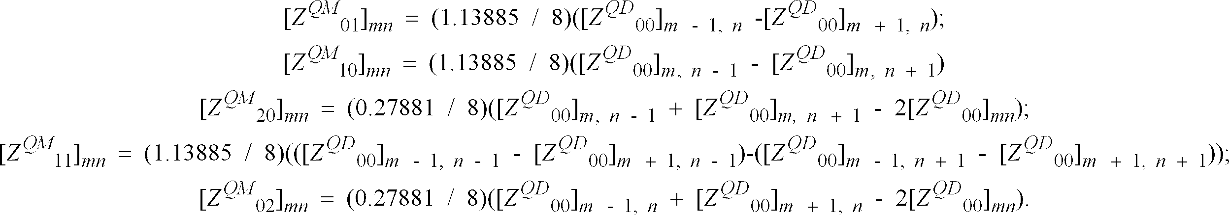
ADAPTIVE AC PREDICTOR 110 is transformed blocks of image data with modified DC and AC coefficients,The modified DC and AC coefficient values in each block are made consistent by an AC/DC
CONSISTENCY CHECK module 120. The AC/DCCONSISTENCY CHECK module 120 with inputsand the quantization table, Qtab produces a consistent set of DC and AC coefficient values which are denoted as The DC and AC coefficient values in each block
 are consistent if, when quantized by the corresponding Qtab entry, they result in quantized DC and AC coefficient values which are the same as those in
 If
If is not consistent, the AC/DC
CONSISTENCY CHECK module 120 increases or decreases the appropriate coefficient values in each blockuntil the corresponding DC and AC coefficient values are made consistent. This method of consistency checking introduces the smallest magnitude change of the coefficient values. The consistent blocks of DCT representative data, are then transformed back into a pixel representation space by a well-known
INVERSE DCT module 130 to form blocks of reconstructed image data,
- An alternate preferred embodiment of the present invention is shown in Figure 3. The modules in Figure 3 which are equivalently numbered to those modules in Figure 2 are functionally identical. The embodiment in Figure 3 is comprised of an additional DC
CONSISTENCY CHECK module 105, and an ACCONSISTENCY CHECK module 115, but does not include the combined AC/DC CONSISTENCY CHECK module 120 (shown in Figure 2). The DCCONSISTENCY CHECK module 105 takes inputsand Qtab and makes consistent with
 in the same manner described for the AC/DC CONSISTENCY CHECK module 120 (shown in Figure 2) to produce
 The AC
CONSISTENCY CHECK module 115 takes inputsand Qtab and makes the AC coefficients (i.e., i≠0 or j≠0) consistent with in the same manner described for the AC/DC CONSISTENCY CHECK module 120 (shown in Figure 2) to produce

- As is well known in the art, the reconstructed image data may be used by any suitable computing station, such as
workstations - A detailed block diagram of the
ADAPTIVE DC CORRELATOR 100 is shown in Fig. 4. Dequantized transformed blocks of image data,are passed to the EXTRACT
DC COEFFICIENT module 140 which extracts the DC coefficient from each block which is denoted asThe DC low pass filter (LPF)
module 150 generates a low pass filtered version of thedenoted as by convolving
 with a low pass filter denoted as [B].

low pass filter 150, [B], is a 3x3 element matrix with the following coefficients:
- An alternate embodiment of the low pass filtering operation denoted by equation (2) is given by equation (4).

- A COMPUTE
BLOCK ACTIVITY module 160 determines the activity for each dequantized transformed block of image data,The output of this
module 160 is an activity indicator, α, which takes on values greater than or equal to 0.0 and less than 1.0. Each blockis comprised of one DC coefficient (for i=0 and j=0) value and 63 AC coefficient values (for i≠0 or j≠0). The nomenclature illustrated in
block 90 is an alternate representation ofillustrating the diagonal zig-zag ordering as defined by the JPEG international standard; the index k represents the AC coefficient's index. Each ACk coefficient value in a block is examined and determined if the coefficient takes on a zero or a non-zero value. Each index of k with a non-zero coefficient value is stored in memory (not shown). The stored indices are retrieved from memory and the maximum index value k is determined and is denoted as knz. The activity measure α is calculated by taking the ratio of knz and the numerical value 64.

- In conjunction with the computing of the activity of a
block 90, a maximum local gradient is computed between the DC coefficient of ablock 90 and the DC coefficient from its eight nearest neighbors by the COMPUTE MAXIMUMLOCAL GRAD module 170. Thismodule 170 determines the maximum absolute value difference between the DC value of the current block and the DC values of the eight nearest neighbor blocks as denoted by Δmax.
-1 ≤ u ≤ 1, and -1 ≤v ≤ 1. - The original dequantized DC valueslow pass filtered DC values
 the activity measure α, and the maximum local gradient Δmax are inputs to an
ADAPTIVE FILTER module 180 to generate an adaptively filtered DC coefficient,The
ADAPTIVE FILTER module 180 adaptively combines thecoefficients to produce according to the following logic:
 Where ΔThresh is a user defined value and is preferably set to 256 for pixel representative data which has a binary representation of 8 bits per pixel for the JPEG baseline. According to the above logic, the low pass filtered DC coefficient
 is combined with the original dequantized DC coefficient
 only if Δmax is less than ΔThresh. This is a switching mechanism which allows the adaptive filtering to be invoked in image regions for slowly varying intensity. The adaptively filtered DC coefficient
 replaces
 by the INSERT
DC COEFFICIENT module 190 to produce a block of quantized transform representative data with a modified DC coefficient,
- As shown in Figure 2,is an input to the ADAPTIVE

AC PREDICTOR module 110 as previously described; and as shown in Figure 3,is an input to the DC
CONSISTENCY CHECK module 105. -
- 10
- camera
- 20
- lens
- 25
- image
- 30
- personal computer card (PCC)
- 40
- workstation
- 50
- monitor
- 60
- workstation
- 70
- monitor
- 80
- decoder
- 90
- block
- 100
- adaptive DC correlator
- 110
- adaptive AC predictor module
- 120
- consistency check module
- 130
- inverse DCT module
- 140
- extract DC coefficient
- 150
- low pass filter
- 160
- compute block activity
- 170
- compute maximum local grad module
- 180
- adaptive filter module
- 190
- insert DC coefficient module
Claims (10)
- An improved method for removing blocking artifacts in regions of slowly varying intensity in an electronic image decoded from a transform-coded representation of an image, the method comprising the steps of:(a) receiving signals indicative of DC and AC coefficient values of transformed blocks of image data;(b) dequantizing the quantized coefficient values;(c) modifying the DC value in each of the blocks based on the level of activity within the block and the DC values in neighboring blocks;(d) replacing the AC values in each block with the AC predicted values based on the modified DC values in the block and in neighboring blocks; and(e) reconstructing the image using the modified DC and AC coefficient values.
- The method as in claim 1, wherein step (c) further comprises computing the activity level by identifying a highest AC coefficient index that represents a non-zero frequency component in the block.
- The method as in claim 1, wherein step (c) further comprises computing the activity level by calculating a maximum absolute value difference between the DC value of a block and its eight nearest neighbors for forming a local gradient.
- The method as in claim 1, wherein step (c) further comprises modifying the DC value by convolving a low pass filter with the DC coefficients derived from the received transformed blocks of image data and replacing the DC coefficient derived from the received transformed blocks of image data with the convolved DC coefficient if a predetermined criterion is met.
- The method as in claim 4, wherein the predetermined criterion includes determining when the local gradient is less than a threshold.
- The method as in claim 1 further comprising performing adaptive AC prediction on the result of step (d).
- The method as in claim 1 further comprising performing a consistency check of the results of the modified DC values and AC predicted values.
- A computer for receiving signals indicative of DC and AC coefficient values of transformed blocks of image data and for removing artifacts of slowly varying intensity from the image data, the computer comprising:(a) means for dequantizing coefficient values;(b) means for modifying the DC value in each of the blocks based on the level of activity within the block and the DC values in neighboring blocks; and(c) means for replacing the AC values in each block with the AC predicted values based on the level of activity within the block and the modified DC values in neighboring blocks.
- The computer as in claim 8 further comprising means for computing the activity level by identifying a highest AC coefficient index that represents a non-zero frequency component in the block.
- The computer as in claim 8 further comprising means for computing the activity level by calculating a maximum absolute value difference between the DC value of a block and its eight nearest neighbors for forming a local gradient.
Applications Claiming Priority (2)
| Application Number | Priority Date | Filing Date | Title |
|---|---|---|---|
| US630553 | 1996-04-10 | ||
| US08/630,553 US5737451A (en) | 1996-04-10 | 1996-04-10 | Method and apparatus for suppressing blocking artifacts in block-transform coded images |
Publications (2)
| Publication Number | Publication Date |
|---|---|
| EP0801506A2 true EP0801506A2 (en) | 1997-10-15 |
| EP0801506A3 EP0801506A3 (en) | 1999-12-22 |
Family
ID=24527633
Family Applications (1)
| Application Number | Title | Priority Date | Filing Date |
|---|---|---|---|
| EP97200913A Withdrawn EP0801506A3 (en) | 1996-04-10 | 1997-03-26 | A method and apparatus for suppressing blocking artifacts in block-transform coded images |
Country Status (2)
| Country | Link |
|---|---|
| US (1) | US5737451A (en) |
| EP (1) | EP0801506A3 (en) |
Cited By (11)
| Publication number | Priority date | Publication date | Assignee | Title |
|---|---|---|---|---|
| WO2000033254A1 (en) * | 1998-12-03 | 2000-06-08 | Koninklijke Philips Electronics N.V. | Post-processing decompressed images |
| EP1081958A1 (en) * | 1999-08-31 | 2001-03-07 | Lucent Technologies Inc. | Method and apparatus for macroblock DC and AC coefficient prediction for video coding |
| DE19718063C2 (en) * | 1997-04-29 | 2001-05-17 | Rohde & Schwarz | Method for detecting and quantifying image changes in a video image that is processed with a block-based, data-reducing video code |
| DE19734881C2 (en) * | 1997-07-30 | 2002-04-25 | Lg Electronics Inc | Methods for reducing blockage artifacts generated when encoding film recordings |
| DE19829468C2 (en) * | 1997-09-09 | 2002-07-18 | Lg Electronics Inc | Method for eliminating blocking artifacts in a system for encoding moving pictures at low bit rate |
| EP1589762A1 (en) * | 2004-04-23 | 2005-10-26 | Samsung Electronics Co., Ltd. | Image compression with reduced block artefacts |
| GB2429593A (en) * | 2005-08-26 | 2007-02-28 | Electrosonic Ltd | Data compressing using a wavelet compression scheme |
| EP2018070A1 (en) * | 2007-07-17 | 2009-01-21 | Thomson Licensing | Method for processing images and the corresponding electronic device |
| WO2012119655A1 (en) * | 2011-03-10 | 2012-09-13 | Telefonaktiebolaget L M Ericsson (Publ) | Decoding of transforms with curved basis functions |
| EP1542163B1 (en) * | 2003-12-09 | 2016-09-14 | Sagemcom Broadband SAS | Method of reducing blocking artefacts in block compressed images |
| US9992252B2 (en) | 2015-09-29 | 2018-06-05 | Rgb Systems, Inc. | Method and apparatus for adaptively compressing streaming video |
Families Citing this family (20)
| Publication number | Priority date | Publication date | Assignee | Title |
|---|---|---|---|---|
| JP3222780B2 (en) * | 1996-08-29 | 2001-10-29 | 旭光学工業株式会社 | Image compression device |
| KR100229796B1 (en) * | 1996-08-30 | 1999-11-15 | 전주범 | Image decoding system with compensation function for degraded image |
| KR100303685B1 (en) * | 1996-09-30 | 2001-09-24 | 송문섭 | Image predictive encoding device and method |
| JP3800704B2 (en) * | 1997-02-13 | 2006-07-26 | ソニー株式会社 | Video signal processing apparatus and method |
| KR100243225B1 (en) * | 1997-07-16 | 2000-02-01 | 윤종용 | Signal adaptive filtering method for reducting blocking effect and ringing noise and filter thereof |
| KR100366643B1 (en) * | 1998-11-25 | 2003-02-19 | 삼성전자 주식회사 | Method and apparatus for de-blocking |
| US7003174B2 (en) * | 2001-07-02 | 2006-02-21 | Corel Corporation | Removal of block encoding artifacts |
| US6983079B2 (en) * | 2001-09-20 | 2006-01-03 | Seiko Epson Corporation | Reducing blocking and ringing artifacts in low-bit-rate coding |
| US7003170B1 (en) | 2002-09-20 | 2006-02-21 | Pegasus Imaging Corporation | Methods and apparatus for improving quality of block-transform coded images |
| US6931061B2 (en) * | 2002-11-13 | 2005-08-16 | Sony Corporation | Method of real time MPEG-4 texture decoding for a multiprocessor environment |
| US7643688B2 (en) * | 2003-10-10 | 2010-01-05 | Hewlett-Packard Development Company, L.P. | Reducing artifacts in compressed images |
| US7570818B2 (en) * | 2003-10-17 | 2009-08-04 | Hewlett-Packard Development Company, L.P. | Method for deblocking and transcoding a media stream |
| US7388999B2 (en) * | 2003-10-29 | 2008-06-17 | Hewlett-Packard Development Company, L.P. | Transformations for denoising images |
| US20060034531A1 (en) * | 2004-05-10 | 2006-02-16 | Seiko Epson Corporation | Block noise level evaluation method for compressed images and control method of imaging device utilizing the evaluation method |
| JP4533081B2 (en) * | 2004-10-12 | 2010-08-25 | キヤノン株式会社 | Image encoding apparatus and method |
| WO2008071028A1 (en) * | 2006-12-11 | 2008-06-19 | Thomson Licensing | Method of encoding an image and device implementing said method |
| EP2127390A2 (en) * | 2006-12-28 | 2009-12-02 | Thomson Licensing | Detecting block artifacts in coded images and video |
| US8238675B2 (en) * | 2008-03-24 | 2012-08-07 | Microsoft Corporation | Spectral information recovery for compressed image restoration with nonlinear partial differential equation regularization |
| US9398300B2 (en) * | 2011-10-07 | 2016-07-19 | Texas Instruments Incorporated | Method, system and apparatus for intra-prediction in video signal processing using combinable blocks |
| CN115278232B (en) | 2015-11-11 | 2024-12-10 | 三星电子株式会社 | Method for decoding video and method for encoding video |
Family Cites Families (7)
| Publication number | Priority date | Publication date | Assignee | Title |
|---|---|---|---|---|
| US4774574A (en) * | 1987-06-02 | 1988-09-27 | Eastman Kodak Company | Adaptive block transform image coding method and apparatus |
| US5001559A (en) * | 1989-10-12 | 1991-03-19 | International Business Machines Corporation | Transform coding using coefficient prediction techniques |
| US5146326A (en) * | 1989-11-14 | 1992-09-08 | Fujitsu Limited | Coded picture information decoding apparatus having means for improving picture distortion |
| EP0585573A3 (en) * | 1992-08-31 | 1994-07-13 | Ibm | System and method for suppressing blocking artifacts in decoded transform coded images |
| JP3466705B2 (en) * | 1993-05-28 | 2003-11-17 | ゼロックス・コーポレーション | How to decompress compressed images |
| KR0128881B1 (en) * | 1994-04-30 | 1998-04-10 | 배순훈 | Digital image decoder |
| US5590064A (en) * | 1994-10-26 | 1996-12-31 | Intel Corporation | Post-filtering for decoded video signals |
-
1996
- 1996-04-10 US US08/630,553 patent/US5737451A/en not_active Expired - Fee Related
-
1997
- 1997-03-26 EP EP97200913A patent/EP0801506A3/en not_active Withdrawn
Cited By (24)
| Publication number | Priority date | Publication date | Assignee | Title |
|---|---|---|---|---|
| DE19718063C2 (en) * | 1997-04-29 | 2001-05-17 | Rohde & Schwarz | Method for detecting and quantifying image changes in a video image that is processed with a block-based, data-reducing video code |
| DE19734881C2 (en) * | 1997-07-30 | 2002-04-25 | Lg Electronics Inc | Methods for reducing blockage artifacts generated when encoding film recordings |
| DE19829468C2 (en) * | 1997-09-09 | 2002-07-18 | Lg Electronics Inc | Method for eliminating blocking artifacts in a system for encoding moving pictures at low bit rate |
| US6317522B1 (en) | 1998-12-03 | 2001-11-13 | Philips Electronics North America Corp. | Systems and methods for post-processing decompressed images |
| WO2000033254A1 (en) * | 1998-12-03 | 2000-06-08 | Koninklijke Philips Electronics N.V. | Post-processing decompressed images |
| US6977961B1 (en) | 1999-08-31 | 2005-12-20 | Lucent Technologies Inc. | Method and apparatus for macroblock DC and AC coefficient prediction for video coding |
| EP1081958A1 (en) * | 1999-08-31 | 2001-03-07 | Lucent Technologies Inc. | Method and apparatus for macroblock DC and AC coefficient prediction for video coding |
| WO2001017266A1 (en) * | 1999-08-31 | 2001-03-08 | Lucent Technologies Inc. | Method and apparatus for macroblock dc and ac coefficient prediction for video coding |
| EP1542163B1 (en) * | 2003-12-09 | 2016-09-14 | Sagemcom Broadband SAS | Method of reducing blocking artefacts in block compressed images |
| EP1589762A1 (en) * | 2004-04-23 | 2005-10-26 | Samsung Electronics Co., Ltd. | Image compression with reduced block artefacts |
| US9204170B2 (en) | 2005-08-26 | 2015-12-01 | Rgb Systems, Inc. | Method for image data processing utilizing multiple transform engines |
| US10244263B2 (en) | 2005-08-26 | 2019-03-26 | Rgb Systems, Inc. | Method and apparatus for packaging image data for transmission over a network |
| US10051288B2 (en) | 2005-08-26 | 2018-08-14 | Rgb Systems, Inc. | Method and apparatus for compressing image data using a tree structure |
| GB2429593A (en) * | 2005-08-26 | 2007-02-28 | Electrosonic Ltd | Data compressing using a wavelet compression scheme |
| US9930364B2 (en) | 2005-08-26 | 2018-03-27 | Rgb Systems, Inc. | Method and apparatus for encoding image data using wavelet signatures |
| US9924199B2 (en) | 2005-08-26 | 2018-03-20 | Rgb Systems, Inc. | Method and apparatus for compressing image data using compression profiles |
| CN101779463B (en) * | 2007-07-17 | 2012-05-23 | 汤姆森许可贸易公司 | Method for processing images and the corresponding electronic device |
| KR101500781B1 (en) * | 2007-07-17 | 2015-03-09 | 톰슨 라이센싱 | Method for processing images and the corresponding electronic device |
| US8285064B2 (en) | 2007-07-17 | 2012-10-09 | Thomson Licensing | Method for processing images and the corresponding electronic device |
| WO2009010515A1 (en) * | 2007-07-17 | 2009-01-22 | Thomson Licensing | Method for processing images and the corresponding electronic device |
| EP2018070A1 (en) * | 2007-07-17 | 2009-01-21 | Thomson Licensing | Method for processing images and the corresponding electronic device |
| US8515191B2 (en) | 2011-03-10 | 2013-08-20 | Telefonaktiebolaget Lm Ericsson (Publ) | Decoder and a method therof for improving decoding of image and video signals |
| WO2012119655A1 (en) * | 2011-03-10 | 2012-09-13 | Telefonaktiebolaget L M Ericsson (Publ) | Decoding of transforms with curved basis functions |
| US9992252B2 (en) | 2015-09-29 | 2018-06-05 | Rgb Systems, Inc. | Method and apparatus for adaptively compressing streaming video |
Also Published As
| Publication number | Publication date |
|---|---|
| EP0801506A3 (en) | 1999-12-22 |
| US5737451A (en) | 1998-04-07 |
Similar Documents
| Publication | Publication Date | Title |
|---|---|---|
| US5737451A (en) | Method and apparatus for suppressing blocking artifacts in block-transform coded images | |
| US6427031B1 (en) | Method for removing artifacts in an electronic image decoded from a block-transform coded representation of an image | |
| CA2097951C (en) | Compression and reconstruction of radiological images | |
| US6985632B2 (en) | Image processing system, image processing apparatus, and image processing method | |
| EP0771507B1 (en) | Method and apparatus for reduction of image data compression noise | |
| EP0635985B1 (en) | Improved decompression standard for ADCT-compressed document images | |
| EP0626790B1 (en) | Segmentation-based JPEG image artifacts reduction | |
| US6870963B2 (en) | Configurable pattern optimizer | |
| US20050100235A1 (en) | System and method for classifying and filtering pixels | |
| US20050100241A1 (en) | System and method for reducing ringing artifacts in images | |
| EP1821545A2 (en) | Video encoding and decoding apparatus | |
| EP0577350B1 (en) | A video signal coding and decoding apparatus with an adaptive edge enhancement filter | |
| EP2145476B1 (en) | Image compression and decompression using the pixon method | |
| EP1168823A2 (en) | A method of determining the extent of blocking artifacts in a digital image | |
| JP2004533181A (en) | Selective chrominance decimation for digital images | |
| AU2002305838A1 (en) | Selective chrominance decimation for digital images | |
| US7209594B1 (en) | Methods and apparatus for improving quality of block-transform coded images | |
| JPH07123269A (en) | Corder for picture signal | |
| EP0585573A2 (en) | System and method for suppressing blocking artifacts in decoded transform coded images | |
| Frost et al. | JPEG dequantization array for regularized decompression | |
| JPH08191444A (en) | Video signal decoding device | |
| JP3027605B2 (en) | Image processing device | |
| JPH1023261A (en) | Image-processing unit | |
| Wilson | Compressed radiological images and workstation viewing | |
| EP1589762A1 (en) | Image compression with reduced block artefacts |
Legal Events
| Date | Code | Title | Description |
|---|---|---|---|
| PUAI | Public reference made under article 153(3) epc to a published international application that has entered the european phase |
Free format text: ORIGINAL CODE: 0009012 |
|
| AK | Designated contracting states |
Kind code of ref document: A2 Designated state(s): DE FR GB |
|
| PUAL | Search report despatched |
Free format text: ORIGINAL CODE: 0009013 |
|
| AK | Designated contracting states |
Kind code of ref document: A3 Designated state(s): DE FR GB |
|
| STAA | Information on the status of an ep patent application or granted ep patent |
Free format text: STATUS: THE APPLICATION IS DEEMED TO BE WITHDRAWN |
|
| 18D | Application deemed to be withdrawn |
Effective date: 19990121 |