EP0760308A2 - Seat back latch - Google Patents
Seat back latch Download PDFInfo
- Publication number
- EP0760308A2 EP0760308A2 EP96202163A EP96202163A EP0760308A2 EP 0760308 A2 EP0760308 A2 EP 0760308A2 EP 96202163 A EP96202163 A EP 96202163A EP 96202163 A EP96202163 A EP 96202163A EP 0760308 A2 EP0760308 A2 EP 0760308A2
- Authority
- EP
- European Patent Office
- Prior art keywords
- latch mechanism
- legs
- striker plate
- seat back
- pin
- Prior art date
- Legal status (The legal status is an assumption and is not a legal conclusion. Google has not performed a legal analysis and makes no representation as to the accuracy of the status listed.)
- Granted
Links
Images


Classifications
-
- B—PERFORMING OPERATIONS; TRANSPORTING
- B60—VEHICLES IN GENERAL
- B60N—SEATS SPECIALLY ADAPTED FOR VEHICLES; VEHICLE PASSENGER ACCOMMODATION NOT OTHERWISE PROVIDED FOR
- B60N2/00—Seats specially adapted for vehicles; Arrangement or mounting of seats in vehicles
- B60N2/24—Seats specially adapted for vehicles; Arrangement or mounting of seats in vehicles for particular purposes or particular vehicles
- B60N2/32—Seats specially adapted for vehicles; Arrangement or mounting of seats in vehicles for particular purposes or particular vehicles convertible for other use
- B60N2/36—Seats specially adapted for vehicles; Arrangement or mounting of seats in vehicles for particular purposes or particular vehicles convertible for other use into a loading platform
- B60N2/366—Seats specially adapted for vehicles; Arrangement or mounting of seats in vehicles for particular purposes or particular vehicles convertible for other use into a loading platform characterised by the locking device
-
- B—PERFORMING OPERATIONS; TRANSPORTING
- B60—VEHICLES IN GENERAL
- B60N—SEATS SPECIALLY ADAPTED FOR VEHICLES; VEHICLE PASSENGER ACCOMMODATION NOT OTHERWISE PROVIDED FOR
- B60N2/00—Seats specially adapted for vehicles; Arrangement or mounting of seats in vehicles
- B60N2/02—Seats specially adapted for vehicles; Arrangement or mounting of seats in vehicles the seat or part thereof being movable, e.g. adjustable
- B60N2/22—Seats specially adapted for vehicles; Arrangement or mounting of seats in vehicles the seat or part thereof being movable, e.g. adjustable the back-rest being adjustable
- B60N2/2245—Seats specially adapted for vehicles; Arrangement or mounting of seats in vehicles the seat or part thereof being movable, e.g. adjustable the back-rest being adjustable provided with a lock mechanism on the upper part of the back-rest
-
- B—PERFORMING OPERATIONS; TRANSPORTING
- B60—VEHICLES IN GENERAL
- B60N—SEATS SPECIALLY ADAPTED FOR VEHICLES; VEHICLE PASSENGER ACCOMMODATION NOT OTHERWISE PROVIDED FOR
- B60N2/00—Seats specially adapted for vehicles; Arrangement or mounting of seats in vehicles
- B60N2/24—Seats specially adapted for vehicles; Arrangement or mounting of seats in vehicles for particular purposes or particular vehicles
- B60N2/30—Non-dismountable or dismountable seats storable in a non-use position, e.g. foldable spare seats
- B60N2/3002—Non-dismountable or dismountable seats storable in a non-use position, e.g. foldable spare seats back-rest movements
- B60N2/3004—Non-dismountable or dismountable seats storable in a non-use position, e.g. foldable spare seats back-rest movements by rotation only
- B60N2/3009—Non-dismountable or dismountable seats storable in a non-use position, e.g. foldable spare seats back-rest movements by rotation only about transversal axis
- B60N2/3011—Non-dismountable or dismountable seats storable in a non-use position, e.g. foldable spare seats back-rest movements by rotation only about transversal axis the back-rest being hinged on the cushion, e.g. "portefeuille movement"
Definitions
- the present invention relates to a seat back latch for a seat, in particular, a rear seat, in a motor vehicle, and to a seat back latch mechanism.
- Seat back latches are provided in motor vehicles to allow the seat back to pivot between a substantially upright position (in which the latch mechanism engages a striker plate or bar) and a substantially horizontal position.
- the latch mechanism is released from the striker plate or bar to allow the seat back to pivot about a hinge mechanism located at or near the lowermost edge of the seat back.
- the latch mechanism is usually located in the seat back and is typically released by depressing a push button located in the uppermost surface of the seat back, and the striker plate or bar is secured to the vehicle body.
- a seat back latch mechanism in accordance with the present invention comprises a housing which is substantially tubular and extending in an axial direction, the housing having a substantially rectangular cross-section defined by first and second opposed walls, the first opposed walls having aligned apertures therethrough through which a striker plate can extend; a first spring member defined by a pair of axially extending substantially planar legs with a gap therebetween through which the striker plate can extend when the striker plate extends through the housing, the first spring member being positioned inside the housing with the legs extending alongside the second opposed walls of the housing, the legs having free ends which are positioned outside the housing and which are biased towards one another; a pin movable between a first position in which the pin extends through aligned apertures in the second opposed walls of the housing and the legs of the first spring member and a second position in which the pin is withdrawn from the gap between the legs of the first spring member, the pin being capable of passing through an aperture in the striker plate when the striker plate extends through the housing; a substantially rectangular member pivotally
- the present invention also includes a seat back latch comprising the seat back latch mechanism of the present invention, a striker plate, and a manually operable device.
- a seat back latch 10 in accordance with the present invention comprises a seat back latch mechanism 12 in accordance with the present invention (as will be described in more detail below), a striker plate 14, and a manually operable device in the form of a button 16 connected to the latch mechanism by a substantially rigid rod 18.
- the latch mechanism 12 is secured to a seat back 20 with the button 16 positioned at the top of the seat back and a hinge mechanism (not shown) secured to the seat back towards or at the bottom of the seat back.
- a hinge mechanism (not shown) secured to the seat back towards or at the bottom of the seat back.
- An example of a suitable hinge mechanism is described in our GB patent application no. 9512334.5 filed 16 June 1995.
- the seat back 20 is the seat back of a rear seat in a motor vehicle.
- the striker plate 14 is secured to a portion 22 of the vehicle body.
- the seat back 20 can be pivoted about the hinge mechanism and then locked in any one of four substantially upright positions, or can be pivoted to lie in a substantially horizontal position, by depressing the button 16. Depression of the button 16 whilst the striker plate 14 extends through the latch mechanism 12 moves the latch mechanism to an open position to allow the latch mechanism and the seat back 20 to move relative to the striker plate. Release of the button 16 whilst the striker plate 14 extends through the latch mechanism 12 allows the latch mechanism to move to its closed position to lock the seat back 20 in one of the substantially upright positions.
- the seat back latch mechanism 12 comprises a housing 24, a first spring member 26, a pin 28, a substantially rectangular member 30, a lever member 32, and preferably a second spring member 34.
- the housing 24 is substantially tubular with a substantially rectangular cross-section.
- the housing 24 has a longitudinal axis A and is define by first opposed walls 36,38, and second opposed walls 40,42.
- the first opposed walls 36,38 have aligned apertures 44,46, ( Figure 2) respectively, therein, through which the striker plate 14 can extend.
- the second opposed walls 40,42 have aligned apertures 48,50, ( Figure 2) respectively, therein, through which the pin 28 can extend.
- a striker guide 52 ( Figure 2) may be secured in the aperture 44 in the first opposed wall 36 to assist the entrance of the striker plate 14 into the latch mechanism 12.
- a guideway 54 is preferably secured to the outer surface of the second opposed wall 42 and has an open sided guide channel 56 along which the pin 28 can slide in a direction substantially perpendicular to the axis A. The guideway 54 assists in aligning the pin 28 with the apertures 48,50 in the second opposed walls 40,42.
- An apertured cover 58 may be secured to the outer surface of the other second opposed wall 40 to also provide guidance for the pin 28.
- the first spring member 26 is substantially U-shaped and has a pair of legs 60,62 which are substantially planar.
- the first spring member 26 is secured adjacent its base portion 64 within the housing 24 such that each leg 60,62 extends parallel with, lies alongside, and is normally slightly spaced from, one of the second opposed walls 40,42.
- Each leg 60,62 has an aperture 66,68, respectively, therethrough which aligns with the corresponding aperture 48,50 in the adjacent second opposed wall 40,42, and through which the pin 28 can extend.
- the free end 70,72 of each leg 60,62, respectively extends outside of the housing 24 and is bent to define a C-shaped portion 74,76, respectively, such that the C-shaped portions have open sides which face one another.
- the first spring member 26 is such that the free ends 70,72 of the legs 60,62, respectively, are biased towards one another.
- the rectangular member 30 is in the form of a bent wire spring.
- the rectangular member 30 has a first edge 78 which is positioned in, and is pivotally movable in, the C-shaped portion 74 of the free end 70 of the leg 60 of the first spring member 26. Opposite the first edge 78, the rectangular member 30 has a second edge 80.
- the lever member 32 is in the form of a bent leaf spring.
- the lever member 32 has first and second substantially planar portions 82,84 which lie at an angle to one another.
- the junction of the first and second portions 82,84 defines an intermediate position which has an edge 86 which is positioned in, and is pivotally movable in, the C-shaped portion 76 of the free end 72 of the leg 62 of the first spring member 26.
- the first portion 82 is bent at its end remote from the edge 86 to define a hook portion 88 which is attached to the rod 18 on mounting the latch mechanism 12 in the seat back 20, and to provide a hinge portion 90 within which the second edge 80 of the rectangular member 30 can be positioned and pivotally mounted.
- the second portion 84 is split to define a fork portion 92, the legs of which pass on either side of the open sided channel 56 in the guideway 54.
- the fork portion 92 is attached to one end of the pin 28 by way of a spring clip 94 which extends through the open sides in the channel 56.
- the second spring member 34 is in the form of a leaf spring which has been bent into a substantially Z-shape. One end 96 of the second spring member is secured to the first opposed wall 38, and the other end 98 of the second spring member is secured to the first opposed wall 36.
- the second spring member 34 is positioned to extend between the legs 60,62 adjacent their free ends 70,72, and has a surface or edge 100 directed towards the first portion 82 of the lever member 32 and towards the rectangular member 30, and a bent portion 102 directed towards the striker plate 14 (when the striker plate extends through the latch mechanism 12) and towards the base portion 64 of the first spring member 26.
- the striker plate 14 comprises four apertures 104 therethrough through which the pin 28 of the latch mechanism 12 can extend. Aligned with each aperture is a notch 106 which is formed in a surface 108 of the striker plate 14. When the striker plate 14 extends through the latch mechanism 12, the bent portion 102 of the second spring member 34 engages in one of the notches 106 to align the pin 28 with the corresponding aperture 104 in the striker plate.
- FIGS 6 and 7 show the latch mechanism 12 in its closed (or normal, steady-state) position.
- the striker plate 14 extends through the latch mechanism 12 by way of the apertures 44,46 in the first opposed walls 36,38 of the housing 24. In this position, the striker plate 14 also passes through the gap between the legs 60,62 of the first spring member 26; the bent portion 102 of the second spring member 34 engages one of the notches 106 in the striker plate; and the pin 28 extends through the apertures 48,50 in the second opposed walls 40,42, the apertures 66,68 in the legs, and one of the apertures 104 in the striker plate.
- the rectangular member 30 and the lever member 32 have the relative positions shown in Figure 7. That is, the bias exerted by the legs 60,62 pushes the first edge 78 of the rectangular member 30 and the edge 86 on the lever member 32 towards one another, and, because of the pivotal connections, pushes the second edge 80 of the rectangular member and the hinge portion 90 on the lever member to a position in which they are directed away from the striker plate 14.
- the forces acting on the lever member 32 retain the pin 28 in the position shown (its first position).
- the bias exerted by the legs 60,62 brings the legs into engagement with the striker plate 14 to clamp the striker plate thereby reducing the risk of, and substantially eliminating, rattle noises occurring between the striker plate and the latch mechanism 12.
- the button 16 ( Figure 1) is pushed down towards the latch mechanism.
- This action exerts a force, by way of rod 18 ( Figure 1) on the hook portion 88 of the lever member 32, and due to the pivotal connections, pushes the hook portion and the hinge portion 90 of the lever member and the second edge 80 of the rectangular member 30 towards the second spring member 34 and the striker plate 14, until the rectangular member 30 and the first portion 82 of the lever member substantially lie in a common plane.
- the second spring member 34 is slightly compressed between the striker plate 14 and the hinge portion 90 of the lever member 32/second edge 80 of the rectangular member 30.
- the free ends 70,72 of the legs 60,62 are moved away from one another to increase the gap therebetween and release the grip exerted by the legs on the striker plate 14.
- the lever member 32 pivots about its edge 86 to pull the pin 28 out of the aperture 104 in the striker plate 14.
- the striker plate 14 is now free to move relative to the latch mechanism 12.
- the seat back 20 ( Figure 1) can be pivoted to an alternative upright position and the button 16 released so that the latch mechanism 12 moves back to its closed position and locked to the striker plate 14, or the seat back can be moved to a substantially horizontal position in which the striker plate is removed from the latch mechanism.
- the second spring member 34 moves away from the hinge portion 90 of the lever member 32/second edge 80 of the rectangular member 30, and the rectangular member 30 and the first portion 82 of the lever member remain in the common plane with the pin 28 retracted from the gap between the legs 60,62 of the first spring member 26. In this position, the latch member 12 is ready to receive the insertion of the striker plate 14.
- the surface 108 of the striker plate 14 engages the second spring 34 to move the surface or edge 100 of the second spring member 34 into engagement with the hinge portion 90 of the lever member 32/second edge 80 of the rectangular member 30. This action pushes the hinge portion 90 of the lever member 32 and the second edge 80 of the rectangular member 30 away from the striker plate 14.
- the bent portion 102 of the second spring member 34 locates in a notch 106 in the striker plate 14
- the rectangular member 30 and the lever member 32 can fully return to the position shown in Figures 6 and 7 and the pin 28 passes through the corresponding aperture 104 in the striker plate.
- This arrangement provides for automatic locking of the latch mechanism 12 on the striker plate 14.
- the positive locking of the pin 28 of the latch mechanism 12 with one of the apertures 104 in the striker plate 14 provides a seat back latch 10 with increased strength when compared to previously known arrangements. This increase in strength reduces the risk of failure of the latch should the seat back be subjected to an impact by an object from the rear of the seat back.
- the provision of the possibility of locking the seat back in one of a number of substantially upright positions allows the vehicle occupant to select an upright position dependent on comfort and load space utilisation. It will be appreciated that the number of potential upright positions can easily be changed simply by using a striker plate with a different number of apertures. The feature of the legs gripping the striker plate reduces the risk of rattle noise.
Landscapes
- Engineering & Computer Science (AREA)
- Aviation & Aerospace Engineering (AREA)
- Transportation (AREA)
- Mechanical Engineering (AREA)
- Seats For Vehicles (AREA)
Abstract
Description
- The present invention relates to a seat back latch for a seat, in particular, a rear seat, in a motor vehicle, and to a seat back latch mechanism.
- Seat back latches are provided in motor vehicles to allow the seat back to pivot between a substantially upright position (in which the latch mechanism engages a striker plate or bar) and a substantially horizontal position. The latch mechanism is released from the striker plate or bar to allow the seat back to pivot about a hinge mechanism located at or near the lowermost edge of the seat back. The latch mechanism is usually located in the seat back and is typically released by depressing a push button located in the uppermost surface of the seat back, and the striker plate or bar is secured to the vehicle body.
- It is an object of the present invention to provide an improvement to the previously known arrangements.
- A seat back latch mechanism in accordance with the present invention comprises a housing which is substantially tubular and extending in an axial direction, the housing having a substantially rectangular cross-section defined by first and second opposed walls, the first opposed walls having aligned apertures therethrough through which a striker plate can extend; a first spring member defined by a pair of axially extending substantially planar legs with a gap therebetween through which the striker plate can extend when the striker plate extends through the housing, the first spring member being positioned inside the housing with the legs extending alongside the second opposed walls of the housing, the legs having free ends which are positioned outside the housing and which are biased towards one another; a pin movable between a first position in which the pin extends through aligned apertures in the second opposed walls of the housing and the legs of the first spring member and a second position in which the pin is withdrawn from the gap between the legs of the first spring member, the pin being capable of passing through an aperture in the striker plate when the striker plate extends through the housing; a substantially rectangular member pivotally mounted at a first edge to the free end of one of the legs of the first spring member, the rectangular member having a second edge opposed the first edge; and a lever member secured at one end to one end of the pin outside of the housing, pivotally attached at its other end to the second edge of the rectangular member, and pivotally mounted at a position intermediate its ends to the free end of the other leg of the first spring member; the latch mechanism having a closed position in which the pin is in its first position, and in which the engaging second edge of the rectangular member and the other end of the lever member are directed away from the gap between the legs of the first spring member, and being movable to an open position by pushing the engaging second edge of the rectangular member and the other end of the lever member towards the gap between the legs of the first member to (a) push the free ends of the legs away from one another against the bias of the first spring member to increase the gap therebetween and (b) to pivot the lever member about its intermediate position to move the pin to its second position.
- The present invention also includes a seat back latch comprising the seat back latch mechanism of the present invention, a striker plate, and a manually operable device.
- The present invention will now be described, by way of example, with reference to the accompanying drawings, in which:-
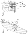
- Figure 1 is a cross-sectional view of a seat back having a seat back latch in accordance with the present invention;
- Figure 2 is a cross-sectional view on the line II-II of Figure 1 with the striker plate secured to the vehicle body;
- Figure 3 is a side view of a seat back latch mechanism in accordance with the present invention as used in the seat back latch of Figure 1;
- Figure 4 is an end view of the seat back latch mechanism of Figure 3;
- Figure 5 is an exploded view of the seat back latch mechanism of Figures 3 and 4;
- Figure 6 is a cross-section view of the seat back latch mechanism of Figures 3 to 5 in its closed position with a striker plate fixed therein;
- Figure 7 is a cross-sectional view on the line VII-VII of Figure 6;
- Figure 8 is a cross-section view of the seat back latch mechanism of Figures 3 to 5 in its open position with a striker plate positioned therein;
- Figure 9 is a cross-sectional view on the line IX-IX of Figure 8;
- Figure 10 is a cross-section view of the seat back latch mechanism of Figures 3 to 5 in its open position with a striker plate removed; and
- Figure 11 is a cross-sectional view on the line XI-XI of Figure 10.
- Referring to Figures 1 and 2, a
seat back latch 10 in accordance with the present invention comprises a seatback latch mechanism 12 in accordance with the present invention (as will be described in more detail below), astriker plate 14, and a manually operable device in the form of abutton 16 connected to the latch mechanism by a substantiallyrigid rod 18. Thelatch mechanism 12 is secured to a seat back 20 with thebutton 16 positioned at the top of the seat back and a hinge mechanism (not shown) secured to the seat back towards or at the bottom of the seat back. An example of a suitable hinge mechanism is described in our GB patent application no. 9512334.5 filed 16 June 1995. Theseat back 20 is the seat back of a rear seat in a motor vehicle. Thestriker plate 14 is secured to aportion 22 of the vehicle body. As will be explained in more detail below, theseat back 20 can be pivoted about the hinge mechanism and then locked in any one of four substantially upright positions, or can be pivoted to lie in a substantially horizontal position, by depressing thebutton 16. Depression of thebutton 16 whilst thestriker plate 14 extends through thelatch mechanism 12 moves the latch mechanism to an open position to allow the latch mechanism and the seat back 20 to move relative to the striker plate. Release of thebutton 16 whilst thestriker plate 14 extends through thelatch mechanism 12 allows the latch mechanism to move to its closed position to lock the seat back 20 in one of the substantially upright positions. - The seat
back latch mechanism 12 will now be described with reference to Figures 3 to 5. Thelatch mechanism 12 comprises ahousing 24, afirst spring member 26, apin 28, a substantiallyrectangular member 30, alever member 32, and preferably asecond spring member 34. Thehousing 24 is substantially tubular with a substantially rectangular cross-section. Thehousing 24 has a longitudinal axis A and is define by firstopposed walls opposed walls opposed walls apertures striker plate 14 can extend. The secondopposed walls apertures pin 28 can extend. A striker guide 52 (Figure 2) may be secured in theaperture 44 in the firstopposed wall 36 to assist the entrance of thestriker plate 14 into thelatch mechanism 12. Aguideway 54 is preferably secured to the outer surface of the secondopposed wall 42 and has an opensided guide channel 56 along which thepin 28 can slide in a direction substantially perpendicular to the axis A. Theguideway 54 assists in aligning thepin 28 with theapertures opposed walls cover 58 may be secured to the outer surface of the other secondopposed wall 40 to also provide guidance for thepin 28. - The
first spring member 26 is substantially U-shaped and has a pair oflegs first spring member 26 is secured adjacent itsbase portion 64 within thehousing 24 such that eachleg opposed walls leg aperture corresponding aperture opposed wall pin 28 can extend. Thefree end leg housing 24 and is bent to define a C-shaped portion first spring member 26 is such that thefree ends legs - The
rectangular member 30 is in the form of a bent wire spring. Therectangular member 30 has afirst edge 78 which is positioned in, and is pivotally movable in, the C-shaped portion 74 of thefree end 70 of theleg 60 of thefirst spring member 26. Opposite thefirst edge 78, therectangular member 30 has asecond edge 80. - The
lever member 32 is in the form of a bent leaf spring. Thelever member 32 has first and second substantiallyplanar portions second portions edge 86 which is positioned in, and is pivotally movable in, the C-shaped portion 76 of thefree end 72 of theleg 62 of thefirst spring member 26. Thefirst portion 82 is bent at its end remote from theedge 86 to define ahook portion 88 which is attached to therod 18 on mounting thelatch mechanism 12 in the seat back 20, and to provide ahinge portion 90 within which thesecond edge 80 of therectangular member 30 can be positioned and pivotally mounted. Thesecond portion 84 is split to define afork portion 92, the legs of which pass on either side of the opensided channel 56 in theguideway 54. Thefork portion 92 is attached to one end of thepin 28 by way of aspring clip 94 which extends through the open sides in thechannel 56. - The
second spring member 34 is in the form of a leaf spring which has been bent into a substantially Z-shape. Oneend 96 of the second spring member is secured to the firstopposed wall 38, and theother end 98 of the second spring member is secured to the firstopposed wall 36. Thesecond spring member 34 is positioned to extend between thelegs free ends edge 100 directed towards thefirst portion 82 of thelever member 32 and towards therectangular member 30, and abent portion 102 directed towards the striker plate 14 (when the striker plate extends through the latch mechanism 12) and towards thebase portion 64 of thefirst spring member 26. - As can be seen from Figure 1, the
striker plate 14 comprises fourapertures 104 therethrough through which thepin 28 of thelatch mechanism 12 can extend. Aligned with each aperture is anotch 106 which is formed in asurface 108 of thestriker plate 14. When thestriker plate 14 extends through thelatch mechanism 12, thebent portion 102 of thesecond spring member 34 engages in one of thenotches 106 to align thepin 28 with thecorresponding aperture 104 in the striker plate. - The operation of the
latch mechanism 12 will now be described with reference to Figures 6 to 11. Figures 6 and 7 show thelatch mechanism 12 in its closed (or normal, steady-state) position. Thestriker plate 14 extends through thelatch mechanism 12 by way of theapertures opposed walls housing 24. In this position, thestriker plate 14 also passes through the gap between thelegs first spring member 26; thebent portion 102 of thesecond spring member 34 engages one of thenotches 106 in the striker plate; and thepin 28 extends through theapertures opposed walls apertures apertures 104 in the striker plate. Therectangular member 30 and thelever member 32 have the relative positions shown in Figure 7. That is, the bias exerted by thelegs first edge 78 of therectangular member 30 and theedge 86 on thelever member 32 towards one another, and, because of the pivotal connections, pushes thesecond edge 80 of the rectangular member and thehinge portion 90 on the lever member to a position in which they are directed away from thestriker plate 14. The forces acting on thelever member 32 retain thepin 28 in the position shown (its first position). Further still, the bias exerted by thelegs striker plate 14 to clamp the striker plate thereby reducing the risk of, and substantially eliminating, rattle noises occurring between the striker plate and thelatch mechanism 12. - In order to move the
latch mechanism 12 to its open or released position (Figures 8 and 9), the button 16 (Figure 1) is pushed down towards the latch mechanism. This action exerts a force, by way of rod 18 (Figure 1) on thehook portion 88 of thelever member 32, and due to the pivotal connections, pushes the hook portion and thehinge portion 90 of the lever member and thesecond edge 80 of therectangular member 30 towards thesecond spring member 34 and thestriker plate 14, until therectangular member 30 and thefirst portion 82 of the lever member substantially lie in a common plane. In this position, thesecond spring member 34 is slightly compressed between thestriker plate 14 and thehinge portion 90 of thelever member 32/second edge 80 of therectangular member 30. As a consequence of this relative movement, the free ends 70,72 of thelegs striker plate 14. Also, thelever member 32 pivots about itsedge 86 to pull thepin 28 out of theaperture 104 in thestriker plate 14. Thestriker plate 14 is now free to move relative to thelatch mechanism 12. This means the seat back 20 (Figure 1) can be pivoted to an alternative upright position and thebutton 16 released so that thelatch mechanism 12 moves back to its closed position and locked to thestriker plate 14, or the seat back can be moved to a substantially horizontal position in which the striker plate is removed from the latch mechanism. - When the
striker plate 14 is removed from the latch mechanism 12 (Figures 10 and 11), thesecond spring member 34 moves away from thehinge portion 90 of thelever member 32/second edge 80 of therectangular member 30, and therectangular member 30 and thefirst portion 82 of the lever member remain in the common plane with thepin 28 retracted from the gap between thelegs first spring member 26. In this position, thelatch member 12 is ready to receive the insertion of thestriker plate 14. - On inserting the
striker plate 14 through theaperture 44 in the firstopposed wall 36 and between thelegs surface 108 of thestriker plate 14 engages thesecond spring 34 to move the surface or edge 100 of thesecond spring member 34 into engagement with thehinge portion 90 of thelever member 32/second edge 80 of therectangular member 30. This action pushes thehinge portion 90 of thelever member 32 and thesecond edge 80 of therectangular member 30 away from thestriker plate 14. When thebent portion 102 of thesecond spring member 34 locates in anotch 106 in thestriker plate 14, therectangular member 30 and thelever member 32 can fully return to the position shown in Figures 6 and 7 and thepin 28 passes through the correspondingaperture 104 in the striker plate. This arrangement provides for automatic locking of thelatch mechanism 12 on thestriker plate 14. - The positive locking of the
pin 28 of thelatch mechanism 12 with one of theapertures 104 in thestriker plate 14 provides a seat back latch 10 with increased strength when compared to previously known arrangements. This increase in strength reduces the risk of failure of the latch should the seat back be subjected to an impact by an object from the rear of the seat back. The provision of the possibility of locking the seat back in one of a number of substantially upright positions allows the vehicle occupant to select an upright position dependent on comfort and load space utilisation. It will be appreciated that the number of potential upright positions can easily be changed simply by using a striker plate with a different number of apertures. The feature of the legs gripping the striker plate reduces the risk of rattle noise. - Although primarily intended to be used with a rear seat of a motor vehicle, it will be appreciated that the present invention could also be adapted to be used with the seat back of a front seat of a motor vehicle.
Claims (13)
- A seat back latch mechanism (12) comprising a housing (24) which is substantially tubular and extending in an axial direction, the housing having a substantially rectangular cross-section defined by first and second opposed walls (36-42), the first opposed walls having aligned apertures (46) therethrough through which a striker plate (14) can extend; a first spring member (26) defined by a pair of axially extending substantially planar legs (60,62) with a gap therebetween through which the striker plate can extend when the striker plate extends through the housing, the first spring member being positioned inside the housing with the legs extending alongside the second opposed walls of the housing, the legs having free ends (70,72) which are positioned outside the housing and which are biased towards one another; a pin (28) movable between a first position in which the pin extends through aligned apertures (48,50,66,68) in the second opposed walls of the housing and the legs of the first spring member and a second position in which the pin is withdrawn from the gap between the legs of the first spring member, the pin being capable of passing through an aperture (104) in the striker plate when the striker plate extends through the housing; a substantially rectangular member (30) pivotally mounted at a first edge (78) to the free end (70) of one of the legs of the first spring member, the rectangular member having a second edge (80) opposed the first edge; and a lever member (32) secured at one end (92) to one end of the pin outside of the housing, pivotally attached at its other end (90) to the second edge of the rectangular member, and pivotally mounted at a position (86) intermediate its ends to the free end (72) of the other leg of the first spring member; the latch mechanism having a closed position in which the pin is in its first position, and in which the engaging second edge of the rectangular member and the other end of the lever member are directed away from the gap between the legs of the first spring member, and being movable to an open position by pushing the engaging second edge of the rectangular member and the other end of the lever member towards the gap between the legs of the first member to (a) push the free ends of the legs away from one another against the bias of the first spring member to increase the gap therebetween and (b) to pivot the lever member about its intermediate position to move the pin to its second position.
- A seat back latch mechanism as claimed in Claim 1, further comprising a second spring member (34) having a substantially Z-shape, the second spring member being mounted on the first opposed walls (36,38) of the housing (24) to extend between the legs (60,62) of the first spring member (26) adjacent their free ends, the second spring member being engageable with the striker plate (14) when the striker plate extends through the housing, and, when the latch mechanism is in its open position and when the striker plate extends through the housing, acts on the second edge (80) of the rectangular member (30) and the other end (90) of the lever member (32) to bias the latch mechanism towards its closed position.
- A seat back latch mechanism as claimed in Claim 2, wherein the second spring (34) member is in the form of a leaf spring.
- A seat back latch mechanism as claimed in any one of Claims 1 to 3, wherein the rectangular member (30) is in the form of a bent wire spring.
- A seat back latch mechanism as claimed in any one of Claims 1 to 4, wherein the lever member (32) is in the form of a leaf spring.
- A seat back latch mechanism as claimed in any one of Claims 1 to 5, wherein the pin (28) is slidable between its first and second positions in a guideway (54) attached to the housing (24).
- A seat back latch mechanism as claimed in any one of Claims 1 to 6, wherein the free end (70,72) of each leg (60,62) of the first spring member (26) is bent into a substantially C-shape to define a portion of the pivotal connection between the free end of each leg and the first edge (78) of the rectangular member (30) and the intermediate position (86) of the lever member (32) respectively.
- A seat back latch mechanism as claimed in any one of Claims 1 to 7, wherein the first spring member (26) has a substantially U-shape defining a base portion (64) and the planar legs (60,62), the first spring member being secured to the housing (24) adjacent the base portion thereof.
- A seat back latch comprising a seat back latch mechanism as claimed in any one of Claims 1 to 8; a striker plate (14) which can extend through the aligned apertures (46) in the first opposed walls (36,38) of the housing (24) of the latch mechanism and the gap between the legs (60,62) in the first spring member (26), the striker plate having at least one aperture (104) through which the pin (28) can extend in the closed position of the latch mechanism; and a manually operable device (16) connected to the other end (90) of the lever member (32) or to the second edge (80) of the rectangular member (30) for moving the latch mechanism from its closed position to its open position.
- A seat back latch as claimed in Claim 9, wherein the gap between the legs (60,62) of the first spring member (26) is such that the legs grip the striker plate (14) when the latch mechanism is in the closed position.
- A seat back latch as claimed in Claim 9 or Claim 10, wherein the striker plate (14) has two or more apertures (104) therethrough, the pin (28) extending through a selected aperture when the latch mechanism is in its closed position.
- A seat back latch as claimed in any one of Claims 9 to 11, in which the latch mechanism has a second spring member (34) as claimed in Claim 2 or Claim 3, wherein the striker plate (14) has aligned with the or each aperture (104) therethrough a corresponding notch (106) in its surface (108), the second spring member having a bent portion (102) for locating in the or one of the notches to align the pin with the corresponding aperture in the striker plate.
- A seat back latch as claimed in any one of Claims 9 to 12, wherein the manually operable device comprises a button (16) which is connected to the other end (90) of the lever member (32) or to the second edge (80) of the rectangular member (30) by a substantially rigid rod (18).
Applications Claiming Priority (2)
| Application Number | Priority Date | Filing Date | Title |
|---|---|---|---|
| GB9516914 | 1995-08-18 | ||
| GB9516914A GB2305209B (en) | 1995-08-18 | 1995-08-18 | Seat back latch |
Publications (3)
| Publication Number | Publication Date |
|---|---|
| EP0760308A2 true EP0760308A2 (en) | 1997-03-05 |
| EP0760308A3 EP0760308A3 (en) | 1998-02-25 |
| EP0760308B1 EP0760308B1 (en) | 2001-10-17 |
Family
ID=10779405
Family Applications (1)
| Application Number | Title | Priority Date | Filing Date |
|---|---|---|---|
| EP19960202163 Expired - Lifetime EP0760308B1 (en) | 1995-08-18 | 1996-07-31 | Seat back latch |
Country Status (3)
| Country | Link |
|---|---|
| EP (1) | EP0760308B1 (en) |
| DE (1) | DE69615968T2 (en) |
| GB (1) | GB2305209B (en) |
Cited By (5)
| Publication number | Priority date | Publication date | Assignee | Title |
|---|---|---|---|---|
| FR2778876A1 (en) * | 1998-05-25 | 1999-11-26 | Coutier Moulage Gen Ind | Fastener for inclinable back of passenger vehicle bench seat |
| FR2789638A1 (en) * | 1999-02-16 | 2000-08-18 | Faure Bertrand Equipements Sa | Adjustable seat back for motor vehicle seat has seat locked in each angled position by catch |
| FR2789639A1 (en) * | 1999-02-16 | 2000-08-18 | Cesa | Seat catch for motor vehicle has lock cooperating with catch having lost motion connection to compensate for play |
| FR2789635A1 (en) * | 1999-02-12 | 2000-08-18 | Peugeot | Longitudinally adjustable rear vehicle seat assembly, comprises a mounting located on the side of the vehicle that can be released enabling the folding of the seat assembly |
| FR2818940A1 (en) * | 2001-01-03 | 2002-07-05 | Peugeot Citroen Automobiles Sa | Pivot mechanism, for rear seat of vehicle, has locking mechanism linked to mechanism for immobilising pivot axis to allow easy movement between two positions. |
Families Citing this family (3)
| Publication number | Priority date | Publication date | Assignee | Title |
|---|---|---|---|---|
| JP3810944B2 (en) * | 1999-05-21 | 2006-08-16 | 株式会社大井製作所 | Seat back locking device |
| GB2442518B (en) * | 2006-09-30 | 2009-04-08 | Lander Automotive Ltd | Vehicle seat backrest tilt adjuster with independent release activating a shot bolt latch |
| DE102017214149B4 (en) | 2017-08-14 | 2024-09-12 | Ford Global Technologies, Llc | Locking device of a vehicle seat |
Citations (1)
| Publication number | Priority date | Publication date | Assignee | Title |
|---|---|---|---|---|
| DE4329634A1 (en) * | 1993-09-02 | 1995-03-09 | Ewald Witte Gmbh & Co Kg | Backrest lock |
-
1995
- 1995-08-18 GB GB9516914A patent/GB2305209B/en not_active Expired - Fee Related
-
1996
- 1996-07-31 EP EP19960202163 patent/EP0760308B1/en not_active Expired - Lifetime
- 1996-07-31 DE DE1996615968 patent/DE69615968T2/en not_active Expired - Lifetime
Patent Citations (1)
| Publication number | Priority date | Publication date | Assignee | Title |
|---|---|---|---|---|
| DE4329634A1 (en) * | 1993-09-02 | 1995-03-09 | Ewald Witte Gmbh & Co Kg | Backrest lock |
Cited By (5)
| Publication number | Priority date | Publication date | Assignee | Title |
|---|---|---|---|---|
| FR2778876A1 (en) * | 1998-05-25 | 1999-11-26 | Coutier Moulage Gen Ind | Fastener for inclinable back of passenger vehicle bench seat |
| FR2789635A1 (en) * | 1999-02-12 | 2000-08-18 | Peugeot | Longitudinally adjustable rear vehicle seat assembly, comprises a mounting located on the side of the vehicle that can be released enabling the folding of the seat assembly |
| FR2789638A1 (en) * | 1999-02-16 | 2000-08-18 | Faure Bertrand Equipements Sa | Adjustable seat back for motor vehicle seat has seat locked in each angled position by catch |
| FR2789639A1 (en) * | 1999-02-16 | 2000-08-18 | Cesa | Seat catch for motor vehicle has lock cooperating with catch having lost motion connection to compensate for play |
| FR2818940A1 (en) * | 2001-01-03 | 2002-07-05 | Peugeot Citroen Automobiles Sa | Pivot mechanism, for rear seat of vehicle, has locking mechanism linked to mechanism for immobilising pivot axis to allow easy movement between two positions. |
Also Published As
| Publication number | Publication date |
|---|---|
| GB2305209A (en) | 1997-04-02 |
| GB2305209A8 (en) | 1997-04-21 |
| GB9516914D0 (en) | 1995-10-18 |
| EP0760308B1 (en) | 2001-10-17 |
| DE69615968D1 (en) | 2001-11-22 |
| EP0760308A3 (en) | 1998-02-25 |
| GB2305209B (en) | 1999-07-14 |
| DE69615968T2 (en) | 2002-10-17 |
Similar Documents
| Publication | Publication Date | Title |
|---|---|---|
| US7249813B2 (en) | Retraction device for drawers | |
| CA1184840A (en) | Seat positioner | |
| US6742846B1 (en) | Modified head restraint assembly for motor vehicle seats | |
| US5700056A (en) | Securable locking device for a movable element of an automobile vehicle seat | |
| US6921227B1 (en) | Retaining spring for detachably connecting two components | |
| EP1849649B1 (en) | Device for fastening a child seat to a fixed striker in a motor vehicle | |
| US4545097A (en) | Lock for a safety belt | |
| US20020079418A1 (en) | Positive engagement latch | |
| EP0760308B1 (en) | Seat back latch | |
| US10584521B2 (en) | Mechanism to open hood | |
| JPH01256677A (en) | Latch housing and assembly of latch housing and step | |
| KR20030037978A (en) | Locking system of seat rail for vehicle | |
| JPS58199232A (en) | Guide apparatus for sliding strip of seat of car | |
| EP0639480A1 (en) | Module retention spring clip | |
| KR960040231A (en) | Auto lock slider for concealed slide fastener | |
| US4802266A (en) | Seat belt buckle | |
| JPH0624484B2 (en) | Belt locking device for safety belt device | |
| EP1025774A2 (en) | Seat belt buckle | |
| JP3704578B2 (en) | Slide rail structure for vehicle seat | |
| US5611580A (en) | Release mechanism for fuel filler door | |
| JP5430331B2 (en) | Lock unit mounting structure for vehicle seat slide lock device | |
| GB1570062A (en) | Push button lock for safety belts | |
| JP4097115B2 (en) | Buckle for seat belt | |
| GB2215586A (en) | Safety belt system with backrest locking mechanism | |
| CN109072638B (en) | Motor vehicle door handle device with guide element of handle hook |
Legal Events
| Date | Code | Title | Description |
|---|---|---|---|
| PUAI | Public reference made under article 153(3) epc to a published international application that has entered the european phase |
Free format text: ORIGINAL CODE: 0009012 |
|
| AK | Designated contracting states |
Kind code of ref document: A2 Designated state(s): DE ES FR IT |
|
| RAP1 | Party data changed (applicant data changed or rights of an application transferred) |
Owner name: DELPHI AUTOMOTIVE SYSTEMS DEUTSCHLAND GMBH |
|
| PUAL | Search report despatched |
Free format text: ORIGINAL CODE: 0009013 |
|
| AK | Designated contracting states |
Kind code of ref document: A3 Designated state(s): DE ES FR IT |
|
| 17P | Request for examination filed |
Effective date: 19980825 |
|
| RAP1 | Party data changed (applicant data changed or rights of an application transferred) |
Owner name: LEAR CORPORATION |
|
| GRAG | Despatch of communication of intention to grant |
Free format text: ORIGINAL CODE: EPIDOS AGRA |
|
| 17Q | First examination report despatched |
Effective date: 20001120 |
|
| GRAG | Despatch of communication of intention to grant |
Free format text: ORIGINAL CODE: EPIDOS AGRA |
|
| GRAH | Despatch of communication of intention to grant a patent |
Free format text: ORIGINAL CODE: EPIDOS IGRA |
|
| GRAH | Despatch of communication of intention to grant a patent |
Free format text: ORIGINAL CODE: EPIDOS IGRA |
|
| GRAA | (expected) grant |
Free format text: ORIGINAL CODE: 0009210 |
|
| AK | Designated contracting states |
Kind code of ref document: B1 Designated state(s): DE ES FR IT |
|
| PG25 | Lapsed in a contracting state [announced via postgrant information from national office to epo] |
Ref country code: IT Free format text: LAPSE BECAUSE OF FAILURE TO SUBMIT A TRANSLATION OF THE DESCRIPTION OR TO PAY THE FEE WITHIN THE PRESCRIBED TIME-LIMIT;WARNING: LAPSES OF ITALIAN PATENTS WITH EFFECTIVE DATE BEFORE 2007 MAY HAVE OCCURRED AT ANY TIME BEFORE 2007. THE CORRECT EFFECTIVE DATE MAY BE DIFFERENT FROM THE ONE RECORDED. Effective date: 20011017 Ref country code: FR Free format text: LAPSE BECAUSE OF FAILURE TO SUBMIT A TRANSLATION OF THE DESCRIPTION OR TO PAY THE FEE WITHIN THE PRESCRIBED TIME-LIMIT Effective date: 20011017 |
|
| REF | Corresponds to: |
Ref document number: 69615968 Country of ref document: DE Date of ref document: 20011122 |
|
| PG25 | Lapsed in a contracting state [announced via postgrant information from national office to epo] |
Ref country code: ES Free format text: LAPSE BECAUSE OF FAILURE TO SUBMIT A TRANSLATION OF THE DESCRIPTION OR TO PAY THE FEE WITHIN THE PRESCRIBED TIME-LIMIT Effective date: 20020430 |
|
| EN | Fr: translation not filed | ||
| PLBE | No opposition filed within time limit |
Free format text: ORIGINAL CODE: 0009261 |
|
| STAA | Information on the status of an ep patent application or granted ep patent |
Free format text: STATUS: NO OPPOSITION FILED WITHIN TIME LIMIT |
|
| 26N | No opposition filed | ||
| PGFP | Annual fee paid to national office [announced via postgrant information from national office to epo] |
Ref country code: DE Payment date: 20110727 Year of fee payment: 16 |
|
| PG25 | Lapsed in a contracting state [announced via postgrant information from national office to epo] |
Ref country code: DE Free format text: LAPSE BECAUSE OF NON-PAYMENT OF DUE FEES Effective date: 20130201 |
|
| REG | Reference to a national code |
Ref country code: DE Ref legal event code: R119 Ref document number: 69615968 Country of ref document: DE Effective date: 20130201 |