EP0726064B1 - Screw-rod-connector of an anterior spiral fixation device - Google Patents
Screw-rod-connector of an anterior spiral fixation device Download PDFInfo
- Publication number
- EP0726064B1 EP0726064B1 EP96300411A EP96300411A EP0726064B1 EP 0726064 B1 EP0726064 B1 EP 0726064B1 EP 96300411 A EP96300411 A EP 96300411A EP 96300411 A EP96300411 A EP 96300411A EP 0726064 B1 EP0726064 B1 EP 0726064B1
- Authority
- EP
- European Patent Office
- Prior art keywords
- connector
- bolt
- post
- fastener
- vertebra
- Prior art date
- Legal status (The legal status is an assumption and is not a legal conclusion. Google has not performed a legal analysis and makes no representation as to the accuracy of the status listed.)
- Expired - Lifetime
Links
Images


Classifications
-
- A—HUMAN NECESSITIES
- A61—MEDICAL OR VETERINARY SCIENCE; HYGIENE
- A61B—DIAGNOSIS; SURGERY; IDENTIFICATION
- A61B17/00—Surgical instruments, devices or methods
- A61B17/56—Surgical instruments or methods for treatment of bones or joints; Devices specially adapted therefor
- A61B17/58—Surgical instruments or methods for treatment of bones or joints; Devices specially adapted therefor for osteosynthesis, e.g. bone plates, screws or setting implements
- A61B17/68—Internal fixation devices, including fasteners and spinal fixators, even if a part thereof projects from the skin
- A61B17/70—Spinal positioners or stabilisers, e.g. stabilisers comprising fluid filler in an implant
- A61B17/7001—Screws or hooks combined with longitudinal elements which do not contact vertebrae
- A61B17/7041—Screws or hooks combined with longitudinal elements which do not contact vertebrae with single longitudinal rod offset laterally from single row of screws or hooks
-
- A—HUMAN NECESSITIES
- A61—MEDICAL OR VETERINARY SCIENCE; HYGIENE
- A61B—DIAGNOSIS; SURGERY; IDENTIFICATION
- A61B17/00—Surgical instruments, devices or methods
- A61B17/56—Surgical instruments or methods for treatment of bones or joints; Devices specially adapted therefor
- A61B17/58—Surgical instruments or methods for treatment of bones or joints; Devices specially adapted therefor for osteosynthesis, e.g. bone plates, screws or setting implements
- A61B17/68—Internal fixation devices, including fasteners and spinal fixators, even if a part thereof projects from the skin
- A61B17/70—Spinal positioners or stabilisers, e.g. stabilisers comprising fluid filler in an implant
- A61B17/7001—Screws or hooks combined with longitudinal elements which do not contact vertebrae
- A61B17/7044—Screws or hooks combined with longitudinal elements which do not contact vertebrae also having plates, staples or washers bearing on the vertebrae
-
- A—HUMAN NECESSITIES
- A61—MEDICAL OR VETERINARY SCIENCE; HYGIENE
- A61B—DIAGNOSIS; SURGERY; IDENTIFICATION
- A61B17/00—Surgical instruments, devices or methods
- A61B17/56—Surgical instruments or methods for treatment of bones or joints; Devices specially adapted therefor
- A61B17/58—Surgical instruments or methods for treatment of bones or joints; Devices specially adapted therefor for osteosynthesis, e.g. bone plates, screws or setting implements
- A61B17/68—Internal fixation devices, including fasteners and spinal fixators, even if a part thereof projects from the skin
- A61B17/70—Spinal positioners or stabilisers, e.g. stabilisers comprising fluid filler in an implant
- A61B17/7049—Connectors, not bearing on the vertebrae, for linking longitudinal elements together
-
- A—HUMAN NECESSITIES
- A61—MEDICAL OR VETERINARY SCIENCE; HYGIENE
- A61B—DIAGNOSIS; SURGERY; IDENTIFICATION
- A61B17/00—Surgical instruments, devices or methods
- A61B17/56—Surgical instruments or methods for treatment of bones or joints; Devices specially adapted therefor
- A61B17/58—Surgical instruments or methods for treatment of bones or joints; Devices specially adapted therefor for osteosynthesis, e.g. bone plates, screws or setting implements
- A61B17/68—Internal fixation devices, including fasteners and spinal fixators, even if a part thereof projects from the skin
- A61B17/80—Cortical plates, i.e. bone plates; Instruments for holding or positioning cortical plates, or for compressing bones attached to cortical plates
- A61B17/809—Cortical plates, i.e. bone plates; Instruments for holding or positioning cortical plates, or for compressing bones attached to cortical plates with bone-penetrating elements, e.g. blades or prongs
Definitions
- the present invention broadly concerns devices for use in spinal implant systems, particularly those using spinal rods contoured for connection at various locations along the length of the spinal column. More specifically, the invention concerns an apparatus for spanning between spinal rods to support vertebral fixation elements of the implant system which provide direct engagement to vertebrae of the spinal column. The invention is particularly useful with methods and devices for anterior fixation of the spine.
- An anterior approach allows complete clearance from the spinal canal of bone fragments and/or total resection of a tumor. It also permits fusion of a minimal number of motion segments. In spite of these advantages, the use of anterior approaches has been limited by the risk of complications and other disadvantages of current systems.
- FR-A-2 704 136 discloses a spinal fixation system comprising at least two longitudinal members, a transverse connector and two bolt and fastener arrangements for clamping the transverse connector to the two longitudinal members.
- US-A-5 108 395 discloses a spinal fixation system comprising a pair of spiked clamps provided with screws and an interconnecting plate for fixing to two corresponding vertebrae.
- the Syracuse I-Plate (Danek and Synthes) may use rigid or semi-rigid screws in combination with a plate. Distraction or compression of the bone graft is not possible with this system.
- the CASF Plate marketed by Acromed is designed to be used in a semi-rigid manner.
- the Stafix Plating System marketed by Daruma of Taipei, Taiwan, is an anterior thoracolumbar plate designed to address similar indications. This plate incorporates slots and holes as well as permitting quadrilateral placement of screws.
- the Anterior Thoracolumbar Plating System under development with Danek and Dr. Zdeblick is a slotted plate designed to attach to the anterior lateral aspect of the vertebral body. The plate allows distraction and/or compression through the use of two screw and two bolts.
- the Kaneda device is a system which includes a rod coupler distant from the point of attachment to the vertebral bodies. Rods are inserted through holes in the spinal screw heads which are then attached to the superior and inferior vertebral bodies. Normally two screws are placed in each body, therefore two rods are required. These rods are threaded to allow compression and distraction and are connected to form a solid construct at the end of the procedure.
- the Texas Scottish Rite Hospital System is also a modular spinal system which can be used anterioraly for the management for burst fractures or tumors. This device can be configured much in the same way as the Kaneda device with two screws in the superior and inferior vertebral body, each connected by rods which are in turn connected together.
- the Dunn device is another anterior spinal fixation device for use in tumor or thoracolumbar burst fractures.
- This device similar to Kaneda, involves vertebral body staples, screws positioned in the vertebral body, and two threaded rods connecting a superior and inferior vertebral body to form a rigid construct.
- a spinal fixation system that is readily adapted to provide lateral coupling between spinal rods and multiple stages or segments of the spinal column. Such a system should provide this segmental interconnection without interfering with vertebral areas available for bone grafting to achieve permanent fixation or immobilization of damaged vertebrae.
- a spinal fixation system comprising:
- a spinal fixation system for spanning between a pair of longitudinal members situated adjacent a patient's vertebrae along the sagittal plane.
- the system preferably includes a number of connectors which are engagable to the longitudinal members via clamping surfaces provided in a slot defined in the connector.
- the locking mechanism may include radial splines on the lower surface of the connector and also on a mating face on the bone bolt.
- the spinal fixation system may be used in laterally connecting longitudinal members implanted adjacent a patient's vertebral column.
- the spinal fixation system provides for convenient management of thoracolumbar burst fractures and tumors and which permits anterior load sharing as well as compression and distraction.
- One benefit of the apparatus of the present invention is that it combines means for connecting the vertebral fixation elements to the spinal rods with means for laterally or transversely connecting the spinal rods together.
- An additional benefit is that the invention provides a more compact construct with a lower profile as compared to prior spinal rod constructs employing many individual components to connect vertebrae and spinal rods.
- Yet another benefit achieved by the invention resides in providing segmental coupling or connection of the spinal rods, while permitting a wide variation of orientations at the vertebral fixation elements relative to the spinal rods.
- Another advantage of this invention is that it provides fixation assemblies that can be top loaded, or implanted over bolts after the bolts have been engaged in the vertebrae.
- FIG. 1 is an exploded perspective view of the spinal fixation system of the present invention including a pair of transverse connectors spanning between two spinal rods with a pair of vertebral fixation bolts and corresponding nuts.
- FIG. 2 is an end elevational view of a transverse connector according to one embodiment.
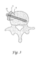
- FIG. 3 is a side cross-sectional view of a transverse connector engaged to a vertebra.
- FIG. 4 is a side elevational view of a bone bolt according to one embodiment of the invention for use with the fixation system shown in FIG. 1.
- FIG. 5 is a bottom elevational view of the lower surface of a transverse connector shown in FIG. 1.
- FIG. 6 is a top elevational view of the bone bolt according to one embodiment as shown in FIG. 2.
- the present invention is useful for anterior internal fixation of the spine which is indicated for thoracolumbar burst fractures with significant canal compromise, vertebral body tumors, lesions due to infection, spondylolisthesis, degenerative discs, and post-laminectomy instability.
- This invention provides a top-loaded, low profile anterior fixation system which requires minimal instrumentation yet permits anterior load sharing and compression or distraction.
- the unique constructs of this invention permit fixation and compression or distraction with only two bolts, two rods and two rod connectors.
- FIG. 1 A spinal fixation system 10 in accordance with a preferred embodiment of the present invention is depicted in FIG. 1.
- the system 10 includes a transverse connector 15 defining a thru-hole 16 and having a lower bone engagement surface 20 and an upper surface 23.
- the transverse connector 15 engages a number of longitudinal members 11 by clamping surface 22 provided in a slot 21 defined in the connector 15.
- the longitudinal members 11 are spinal fixation rods.
- the members 11 are smooth shot peened rods.
- fixation spikes 17 are fixedly attached to the lower surface 20 of the connector 15.
- the lower surface 20 of the connector 15 in combination with an inner surface 19 of the fixation spikes 17 are configured to fit snugly around either side of a vertebra.
- the fixation spikes 17 may be slightly embedded into the vertebra.
- the end of each spike 17 is preferably beveled on its outer surface 24 so that each fixation spike 17 terminates in a wedge shape 18 which may aid in fixing and holding the connector 15 in place over a vertebra.
- Bolts 30 are used to attach the system 10 to the vertebrae. It is understood that “bolt” refers to any of various bone fasteners, including a standard bone screw. The present invention is unique because it requires only one bolt per connector. Previous devices have required two.
- FIG. 4 shows one embodiment of a bolt 30 in detail.
- the bolt 30 has a vertebra engaging portion 31 at a first end 33 and a post 32 at a second end 35.
- the vertebra engaging portion 31 of the bolt 30 may be configured, for example, with cancellous threads for fixation in the spongy bone of the vertebral body.
- the bolt also includes an integral flange 36 for supporting and clamping the connector 15.
- the second end 35 is configured to receive a driving tool.
- the configuration may include an internal or external hex as is well known in the art.
- the fixation system 10 can be top-loaded, i.e., implanted over a bolt 30 after the bolt 30 is engaged to a vertebra. This is advantageous because it reduces the required size of the surgical opening and trauma to the patient. Top-loading also provides a mechanical advantage during implantation of the system.
- the post 32 is insertable through the thru-hole 16 of the connector 15.
- a fastener 40 is provided for each of the bolts 30. The fastener 40 engages to the post 32 of the bolt 30 to secure the connector 15 to the bolt 30 and to clamp the longitudinal members 11 within the slot 21 of the connector 15.
- the longitudinal members 11 and the connector 15 are secured by a single bolt 30.
- the fastener 40 is a threaded nut
- the post 32 of the bolt 30 may included machine threads to engage with the nut.
- the nut or other fastener 40 is then top- tightened with a tool such as a socket wrench.
- the connector 15 may define recesses 41 surrounding each thru-hole 16 defined in the connector 15.
- Each recess can be configured to accept a fastener 40 in low profile so that the fastener 40 does not extend over the upper surface 23 of the connector 15 when it is engaged to a posts 32.
- the recesses 41 can be concave to accept an arcuate underside of the fastener 40.
- the spinal fixation system 10 may also be provided with a locking mechanism configured to prevent the bolts 30 from rotating relative to the connector 15 and the vertebra when the fastener or nut 40 is being tightened onto the bolt 30.
- Tile locking mechanism also prevents the bolts from pulling out over time.
- the locking mechanism includes an annular ring 45 defined on the lower surface 20 (FIG. 5) of the connector 15 and a mating face 50 affixed to each bolt 30 at a location between the post 32 and the vertebrae engaging portion 31.
- the annular ring 45 on the lower surface 20 of the connector 15 is concentrically disposed around the thru-hole 16 and includes a number of radial splines 46. Referring to FIGS.
- the mating face 50 is concentrically disposed around and affixed to the bolt 30 and includes a number of opposing radial splines 51 for interdigitated engagement with the radial splines 46 on the lower surface 20 of the connector 15.
- the annular ring 45 may alternately be a washer affixed to or a ring integrally formed on the lower surface 20 of the connector 15.
- the clamping surface 22 provided by the slot 21 defined in the connector 15 may include a number of scallops (FIG. 6).
- the scallops are configured to receive the longitudinal members 11 in a manner that is well known in the art.
- each scallop can be generally formed at a radius that is slightly smaller than the radius of the longitudinal member 11 which is to be situated within the scallop.
- the scallops provide means for fixing the spinal rods so that the longitudinal members 11 and connector 15 do not shift relative to each other.
- the slot 21 defined in the connector 15 may be smooth and that other means may be provided to firmly fix the longitudinal members 11.
- the slot 21 is smooth and the engagement of the longitudinal members 11 with the connector 15 is secured by a clamping action.
- the tightening of a fastener 40 on the post 32 causes a narrowing of the slot 21 of the connector 15 which in turn causes the connector 15 to securely clamp the longitudinal members 11.
- a dynamic transverse connector 55 (FIG. 1) is slideable along the two longitudinal members 11 for compression and distraction of the vertebral bodies attached to the system 10.
- One or more other connectors 15 may be engaged to the longitudinal members at a fixed location.
- the dynamic connector 55 can be fixed by either tightening the bolt 30 to which the connector 55 is fastened.
- the nuts 40 which attach to the bolts 30 can then be top tightened with a tool such as a socket wrench.
- a spine may be fixated using the system in accordance with the invention by drilling a first hole in the first vertebral body and drilling a second hole in a second vertebral body.
- a bone bolt 30 is engaged to each of the first and second holes.
- the vertebrae are then supported with a fixation system 10 which includes two longitudinal members 11, such as rods.
- a first connector 15 is attached to a first end of each of the longitudinal members 11, and a dynamic rod connector 55 is slidably engaged to the longitudinal members 11.
- One of the bone bolts 30 is engaged to the thru-hole 16 of the first connector 15.
- the dynamic rod connector 55 is situated so that another bolt 30 engages a thru-hole 16 in the dynamic rod connector 55.
- the dynamic rod connector 55 is then slid along the longitudinal members 11 to vary the distance between the first and second vertebrae.
- the post 32 of each bone bolt 30 is then engaged with a nut 40 to secure the fixation system 10 to the vertebrae.
- the dynamic rod connector 55 may be slid along the longitudinal members 11 in the direction towards the fixed connector 15 to compress the vertebrae before engaging bone bolts 30 with the nuts 40.
- the dynamic connector 55 may also be slid in a direction away from the fixed connector for distraction.
- the spinal fixation system 10 is preferably formed of medical grade stainless steel or similar high strength material. Other materials are contemplated, provided the material is strong enough to endure the high loads transmitted through the components, and yet are biocompatible. Specifically, the system could be manufactured in 6A14V titanium or 316LVM stainless steel. The system can be provided in several different sizes ranging from, but not limited to 5.0cm to 13.75cm (2.0 inches to 5.5 inches).
Landscapes
- Health & Medical Sciences (AREA)
- Orthopedic Medicine & Surgery (AREA)
- Life Sciences & Earth Sciences (AREA)
- Neurology (AREA)
- Surgery (AREA)
- Heart & Thoracic Surgery (AREA)
- Engineering & Computer Science (AREA)
- Biomedical Technology (AREA)
- Nuclear Medicine, Radiotherapy & Molecular Imaging (AREA)
- Medical Informatics (AREA)
- Molecular Biology (AREA)
- Animal Behavior & Ethology (AREA)
- General Health & Medical Sciences (AREA)
- Public Health (AREA)
- Veterinary Medicine (AREA)
- Surgical Instruments (AREA)
- Prostheses (AREA)
Abstract
Description
- The present invention broadly concerns devices for use in spinal implant systems, particularly those using spinal rods contoured for connection at various locations along the length of the spinal column. More specifically, the invention concerns an apparatus for spanning between spinal rods to support vertebral fixation elements of the implant system which provide direct engagement to vertebrae of the spinal column. The invention is particularly useful with methods and devices for anterior fixation of the spine.
- Spinal fractures often occur at the thoracolumbar junction. Most of these fractures are burst injuries which are particularly dangerous because retropulsed bone fragments can cause spinal cord or caudal equina injuries. Posterior fixation has long been the primary approach for traumatic spinal injuries of this type.
- The development of posterior internal fixation procedures for burst fractures was a substantial improvement over early approaches of bed rest and body casts. However, several disadvantages to these procedures were discovered. For example, this approach fails to reduce kyphosis or allow complete clearing of the spinal canal. Other complications include pseudoarthroses, late rod disengagement and inadequate reduction. Also, some posterior instrumentations require the fusion to extend at least two levels above and below the injury, particularly at the thoracolumbar junction. The posterior approach is also limited in the viability for use in burst fractures because in such fractures neural compression generally occurs from the anterior direction. Therefore, it is better to decompress and fuse the spine anteriorly. These difficulties have motivated attempts at anterior approaches. Various anterior and posterior spinal fixation devices and methods are discussed in Howard S. An, et al., (1992) Spinal Instrumentation, herein incorporated by reference.
- There are several advantages to anterior internal fixation. An anterior approach allows complete clearance from the spinal canal of bone fragments and/or total resection of a tumor. It also permits fusion of a minimal number of motion segments. In spite of these advantages, the use of anterior approaches has been limited by the risk of complications and other disadvantages of current systems.
- Several plate and screw systems have been designed for anterior instrumentation of the spinal column. FR-A-2 704 136 discloses a spinal fixation system comprising at least two longitudinal members, a transverse connector and two bolt and fastener arrangements for clamping the transverse connector to the two longitudinal members. US-A-5 108 395 discloses a spinal fixation system comprising a pair of spiked clamps provided with screws and an interconnecting plate for fixing to two corresponding vertebrae. The Syracuse I-Plate (Danek and Synthes) may use rigid or semi-rigid screws in combination with a plate. Distraction or compression of the bone graft is not possible with this system. The CASF Plate marketed by Acromed is designed to be used in a semi-rigid manner. This device, as well, does not permit compression or distraction of the bone graft and in addition cannot be used in a rigid construct. The Stafix Plating System marketed by Daruma of Taipei, Taiwan, is an anterior thoracolumbar plate designed to address similar indications. This plate incorporates slots and holes as well as permitting quadrilateral placement of screws. The Anterior Thoracolumbar Plating System under development with Danek and Dr. Zdeblick is a slotted plate designed to attach to the anterior lateral aspect of the vertebral body. The plate allows distraction and/or compression through the use of two screw and two bolts.
- Several modular spinal instrumentation systems were developed for anterior instrumentation. The Kaneda device is a system which includes a rod coupler distant from the point of attachment to the vertebral bodies. Rods are inserted through holes in the spinal screw heads which are then attached to the superior and inferior vertebral bodies. Normally two screws are placed in each body, therefore two rods are required. These rods are threaded to allow compression and distraction and are connected to form a solid construct at the end of the procedure. The Texas Scottish Rite Hospital System is also a modular spinal system which can be used anterioraly for the management for burst fractures or tumors. This device can be configured much in the same way as the Kaneda device with two screws in the superior and inferior vertebral body, each connected by rods which are in turn connected together. The Dunn device is another anterior spinal fixation device for use in tumor or thoracolumbar burst fractures. This device, similar to Kaneda, involves vertebral body staples, screws positioned in the vertebral body, and two threaded rods connecting a superior and inferior vertebral body to form a rigid construct.
- These systems have proved unsatisfactory. Many of these devices such as the Syracuse I-plate and the Casp plate do not allow distraction or compression of a bone graft in fusion cases. Such static systems cannot be used to correct certain disorders such as kyphosis. The systems that do allow distraction and/or compression are often too complicated and involve the use of multiple screws and bolts. The prominent bone screws and rods of some devices increase the danger of vascular injury. Hardware failures, such a screw pull-out, have led to complications, including pseudoarthrosis. Some systems are further limited because they cannot be used in a rigid construct.
- It would therefore be desirable to have a low profile, streamlined system with a minimum of separately implanted components to reduce the amount of time required to implant the system, the risk of vascular injury and the problem of irritation to the surrounding soft tissue of the patient.
- A need exists for devices for anterior fixation which reduce the risks of anterior fixation by providing a mechanism to prevent hardware failures, such as screw pull-out.
- It is desirable to have a spinal fixation system that is readily adapted to provide lateral coupling between spinal rods and multiple stages or segments of the spinal column. Such a system should provide this segmental interconnection without interfering with vertebral areas available for bone grafting to achieve permanent fixation or immobilization of damaged vertebrae.
- There is also a need for low profile, streamlined systems which allow variation of the distances between vertebrae, i.e., compression and distraction, without the need for complicated instrumentation and tools.
- There is currently no system that addresses each of these features in a single apparatus. The present invention addresses these needs and provides other benefits not previously found in spinal fixation systems of the prior art.
- In accordance with the present invention there is provided a spinal fixation system comprising:
- at least two longitudinal members;
- a transverse connector defining a thru-hole and having
- a lower bone engagement surface,
- an opposite upper surface, and
- a number of internal clamping surfaces configured to engage said members;
- a bolt having
- a vertebra engaging portion on a first end,
- a post on a second end, said post being insertable through said thru-hole of said connector, and
- a fastener which in use engages the post, characterised in that the clamping surfaces are provided in a slot defined in the connector, a number of spikes project from said lower surface of said connector, said spikes being configured to engage a vertebra, said bolt has an integral flange between said vertebra engaging portion and said post for supporting said connector; and said fastener when engaged on the post of said bolt secures the connector to the bolt and clamps said connector against said flange of said bolt.
-
- Thus a spinal fixation system is provided for spanning between a pair of longitudinal members situated adjacent a patient's vertebrae along the sagittal plane. The system preferably includes a number of connectors which are engagable to the longitudinal members via clamping surfaces provided in a slot defined in the connector.
- It is preferred that there is provided a locking mechanism configured to prevent the bolt from rotating relative to the connector and the vertebra when the nut is being tightened. The locking mechanism may include radial splines on the lower surface of the connector and also on a mating face on the bone bolt.
- The spinal fixation system may be used in laterally connecting longitudinal members implanted adjacent a patient's vertebral column.
- The spinal fixation system provides for convenient management of thoracolumbar burst fractures and tumors and which permits anterior load sharing as well as compression and distraction.
- One benefit of the apparatus of the present invention is that it combines means for connecting the vertebral fixation elements to the spinal rods with means for laterally or transversely connecting the spinal rods together. An additional benefit is that the invention provides a more compact construct with a lower profile as compared to prior spinal rod constructs employing many individual components to connect vertebrae and spinal rods.
- Yet another benefit achieved by the invention resides in providing segmental coupling or connection of the spinal rods, while permitting a wide variation of orientations at the vertebral fixation elements relative to the spinal rods.
- Another advantage of this invention is that it provides fixation assemblies that can be top loaded, or implanted over bolts after the bolts have been engaged in the vertebrae.
- Other objects and further benefits of the present invention will become apparent to persons of ordinary skill iii the art from the following written description and accompanying figures.
- FIG. 1 is an exploded perspective view of the spinal fixation system of the present invention including a pair of transverse connectors spanning between two spinal rods with a pair of vertebral fixation bolts and corresponding nuts.
- FIG. 2 is an end elevational view of a transverse connector according to one embodiment.
- FIG. 3, is a side cross-sectional view of a transverse connector engaged to a vertebra.
- FIG. 4 is a side elevational view of a bone bolt according to one embodiment of the invention for use with the fixation system shown in FIG. 1.
- FIG. 5 is a bottom elevational view of the lower surface of a transverse connector shown in FIG. 1.
- FIG. 6 is a top elevational view of the bone bolt according to one embodiment as shown in FIG. 2.
- For the purposes of promoting an understanding of the principles of the invention, reference will now be made to the embodiments illustrated in the drawings and specific language will be used to describe the same. It will nevertheless be understood that no limitation of the scope of the invention is thereby intended, such alterations and further modifications in the illustrated devices, and such further applications of the principles of the invention as illustrated therein being contemplated as would normally occur to one skilled in the art to which the invention relates.
- The present invention is useful for anterior internal fixation of the spine which is indicated for thoracolumbar burst fractures with significant canal compromise, vertebral body tumors, lesions due to infection, spondylolisthesis, degenerative discs, and post-laminectomy instability.
- This invention provides a top-loaded, low profile anterior fixation system which requires minimal instrumentation yet permits anterior load sharing and compression or distraction. The unique constructs of this invention permit fixation and compression or distraction with only two bolts, two rods and two rod connectors.
- A
spinal fixation system 10 in accordance with a preferred embodiment of the present invention is depicted in FIG. 1. Thesystem 10 includes atransverse connector 15 defining a thru-hole 16 and having a lowerbone engagement surface 20 and anupper surface 23. Thetransverse connector 15 engages a number oflongitudinal members 11 by clampingsurface 22 provided in aslot 21 defined in theconnector 15. Preferably thelongitudinal members 11 are spinal fixation rods. In one embodiment, themembers 11 are smooth shot peened rods. - Referring to FIGS. 1, 2, and 3, a number of fixation spikes 17 are fixedly attached to the
lower surface 20 of theconnector 15. Thelower surface 20 of theconnector 15 in combination with aninner surface 19 of the fixation spikes 17 are configured to fit snugly around either side of a vertebra. In another application, the fixation spikes 17 may be slightly embedded into the vertebra. The end of each spike 17 is preferably beveled on itsouter surface 24 so that eachfixation spike 17 terminates in awedge shape 18 which may aid in fixing and holding theconnector 15 in place over a vertebra. -
Bolts 30 are used to attach thesystem 10 to the vertebrae. It is understood that "bolt" refers to any of various bone fasteners, including a standard bone screw. The present invention is unique because it requires only one bolt per connector. Previous devices have required two. FIG. 4 shows one embodiment of abolt 30 in detail. Thebolt 30 has avertebra engaging portion 31 at afirst end 33 and apost 32 at asecond end 35. Thevertebra engaging portion 31 of thebolt 30 may be configured, for example, with cancellous threads for fixation in the spongy bone of the vertebral body. The bolt also includes anintegral flange 36 for supporting and clamping theconnector 15. In one embodiment, thesecond end 35 is configured to receive a driving tool. The configuration may include an internal or external hex as is well known in the art. - The
fixation system 10 can be top-loaded, i.e., implanted over abolt 30 after thebolt 30 is engaged to a vertebra. This is advantageous because it reduces the required size of the surgical opening and trauma to the patient. Top-loading also provides a mechanical advantage during implantation of the system. After abolt 30 is engaged to a vertebra by conventional means, thepost 32 is insertable through the thru-hole 16 of theconnector 15. Afastener 40 is provided for each of thebolts 30. Thefastener 40 engages to thepost 32 of thebolt 30 to secure theconnector 15 to thebolt 30 and to clamp thelongitudinal members 11 within theslot 21 of theconnector 15. Thus, thelongitudinal members 11 and theconnector 15 are secured by asingle bolt 30. Where thefastener 40 is a threaded nut, as in the preferred embodiment, thepost 32 of thebolt 30 may included machine threads to engage with the nut. The nut orother fastener 40 is then top- tightened with a tool such as a socket wrench. - The
connector 15 may definerecesses 41 surrounding each thru-hole 16 defined in theconnector 15. Each recess can be configured to accept afastener 40 in low profile so that thefastener 40 does not extend over theupper surface 23 of theconnector 15 when it is engaged to aposts 32. Therecesses 41 can be concave to accept an arcuate underside of thefastener 40. - The
spinal fixation system 10 may also be provided with a locking mechanism configured to prevent thebolts 30 from rotating relative to theconnector 15 and the vertebra when the fastener ornut 40 is being tightened onto thebolt 30. Tile locking mechanism also prevents the bolts from pulling out over time. In one embodiment of the invention, the locking mechanism includes anannular ring 45 defined on the lower surface 20 (FIG. 5) of theconnector 15 and amating face 50 affixed to eachbolt 30 at a location between thepost 32 and thevertebrae engaging portion 31. Theannular ring 45 on thelower surface 20 of theconnector 15 is concentrically disposed around the thru-hole 16 and includes a number ofradial splines 46. Referring to FIGS. 1 and 6, themating face 50 is concentrically disposed around and affixed to thebolt 30 and includes a number of opposingradial splines 51 for interdigitated engagement with the radial splines 46 on thelower surface 20 of theconnector 15. Theannular ring 45 may alternately be a washer affixed to or a ring integrally formed on thelower surface 20 of theconnector 15. - The clamping
surface 22 provided by theslot 21 defined in theconnector 15 may include a number of scallops (FIG. 6). The scallops are configured to receive thelongitudinal members 11 in a manner that is well known in the art. For example, each scallop can be generally formed at a radius that is slightly smaller than the radius of thelongitudinal member 11 which is to be situated within the scallop. The scallops provide means for fixing the spinal rods so that thelongitudinal members 11 andconnector 15 do not shift relative to each other. However, it is understood that theslot 21 defined in theconnector 15 may be smooth and that other means may be provided to firmly fix thelongitudinal members 11. - For example, in one embodiment, the
slot 21 is smooth and the engagement of thelongitudinal members 11 with theconnector 15 is secured by a clamping action. The tightening of afastener 40 on thepost 32 causes a narrowing of theslot 21 of theconnector 15 which in turn causes theconnector 15 to securely clamp thelongitudinal members 11. - The distance between vertebral bodies may be varied. A dynamic transverse connector 55 (FIG. 1) is slideable along the two
longitudinal members 11 for compression and distraction of the vertebral bodies attached to thesystem 10. One or moreother connectors 15 may be engaged to the longitudinal members at a fixed location. After compression or distraction is achieved, thedynamic connector 55 can be fixed by either tightening thebolt 30 to which theconnector 55 is fastened. The nuts 40 which attach to thebolts 30 can then be top tightened with a tool such as a socket wrench. - A spine may be fixated using the system in accordance with the invention by drilling a first hole in the first vertebral body and drilling a second hole in a second vertebral body. A
bone bolt 30 is engaged to each of the first and second holes. The vertebrae are then supported with afixation system 10 which includes twolongitudinal members 11, such as rods. Afirst connector 15 is attached to a first end of each of thelongitudinal members 11, and adynamic rod connector 55 is slidably engaged to thelongitudinal members 11. One of thebone bolts 30 is engaged to the thru-hole 16 of thefirst connector 15. Thedynamic rod connector 55 is situated so that anotherbolt 30 engages a thru-hole 16 in thedynamic rod connector 55. Thedynamic rod connector 55 is then slid along thelongitudinal members 11 to vary the distance between the first and second vertebrae. Thepost 32 of eachbone bolt 30 is then engaged with anut 40 to secure thefixation system 10 to the vertebrae. Thedynamic rod connector 55 may be slid along thelongitudinal members 11 in the direction towards the fixedconnector 15 to compress the vertebrae before engagingbone bolts 30 with the nuts 40. Thedynamic connector 55 may also be slid in a direction away from the fixed connector for distraction. - The
spinal fixation system 10 is preferably formed of medical grade stainless steel or similar high strength material. Other materials are contemplated, provided the material is strong enough to endure the high loads transmitted through the components, and yet are biocompatible. Specifically, the system could be manufactured in 6A14V titanium or 316LVM stainless steel. The system can be provided in several different sizes ranging from, but not limited to 5.0cm to 13.75cm (2.0 inches to 5.5 inches). - While the invention has been illustrated and described in detail and the drawings and foregoing description, the same is to be considered as illustrative and not restrictive in character, it being understood that only the preferred embodiments have been shown and described and that all changes and modifications that come within the scope of the attached claims are to be protected.
Claims (12)
- A spinal fixation system comprising:characterised in that the clamping surfaces (22) are provided in a slot (21) defined in the connector (15,55), a number of spikes (17) project from said lower surface (20) of said connector (15,55), said spikes (17) being configured to engage a vertebra, said bolt (30) has an integral flange (36) between said vertebra engaging portion (31) and said post (32) for supporting said connector (15,55); and said fastener (40) when engaged on the post (32) of said bolt (30) secures the connector (15,55) to the bolt (30) and clamps said connector (15,55) against said flange (36) of said bolt (30).at least two longitudinal members (11);a transverse connector (15,55) defining a thru-hole (16) and havinga lower bone engagement surface (20),an opposite upper surface (23), anda number of internal clamping surfaces (22) configured to engage said members (11);a bolt (30) havinga vertebra engaging portion (31) on a first end (33),a post (32) on a second end (35), said post (32) being insertable through said thru-hole (16) of said connector (15,55), anda fastener (40) which in use engages the post (32),
- The system of claim 1, wherein the post (32) of said bolt (30) is threaded and the fastener (40) is a threaded nut.
- The system of claim 1 or 2, wherein the second end (35) of said bolt (30) is configured to receive a driving tool for driving the bolt (30) into a vertebra.
- The system of claim 3, wherein the second end (35) includes an external hex configured to receive a driving tool.
- The system of claim 3, wherein the second end (35) includes an internal hex configured to receive a driving tool.
- The system of any preceding claim, wherein said thru-hole (16) includes a recess (41) defined in the upper surface (23) of said connector (15,55) and said fastener (40) is sized to be received in the recess (41) without extending above the upper surface (23).
- The system of claim 6, wherein said recess (41) is concave and said fastener (40) includes an arcuate underside, said recess (41) being configured to accept said fastener (40).
- The system of claim 2 or any preceding claim dependent upon claim 2, further comprising a locking mechanism configured to prevent the bolt (30) from rotating relative to said connector (15,55) and the vertebra when the connector (15, 55) is clamped by the threaded nut (40) against said flange (36) of said bolt (30).
- The system of claim 8, wherein said locking mechanism includes:an annular ring (45) defined on the lower surface (20) of said connector (15,55) and concentrically disposed around the thru-hole (16), said annular ring (45) defining a number of radial splines (46); anda mating face (50) affixed to said flange (36) and concentrically disposed around said post (32) of said bolt (30), said mating face (50) defining a number of opposing radial splines (51) for interdigitating engagement with the radial splines (46) on said lower surface (20) of said connector (15,55).
- The system of claim 9, wherein the annular ring (45) is integrally formed on the lower surface (20) of said connector (15,55).
- The system of claim 9, wherein the annular ring (45) is a washer affixed to the lower surface (20) of said connector (15,55).
- The system of claim 2 or any claim dependent upon claim 2, wherein the clamping surfaces (22) are defined by a number of scallops formed in said slot (21), said scallops being shaped to receive and engage said member (11) therein, said scallops surrounding and clamping a portion of said members (11) after the nut (40) has been tightened on the post (32) of the bolt (30).
Applications Claiming Priority (2)
| Application Number | Priority Date | Filing Date | Title |
|---|---|---|---|
| US377658 | 1995-01-25 | ||
| US08/377,658 US5620443A (en) | 1995-01-25 | 1995-01-25 | Anterior screw-rod connector |
Publications (3)
| Publication Number | Publication Date |
|---|---|
| EP0726064A2 EP0726064A2 (en) | 1996-08-14 |
| EP0726064A3 EP0726064A3 (en) | 1998-10-28 |
| EP0726064B1 true EP0726064B1 (en) | 2003-08-27 |
Family
ID=23490021
Family Applications (1)
| Application Number | Title | Priority Date | Filing Date |
|---|---|---|---|
| EP96300411A Expired - Lifetime EP0726064B1 (en) | 1995-01-25 | 1996-01-22 | Screw-rod-connector of an anterior spiral fixation device |
Country Status (8)
| Country | Link |
|---|---|
| US (6) | US5620443A (en) |
| EP (1) | EP0726064B1 (en) |
| JP (1) | JP4540757B2 (en) |
| AT (1) | ATE247931T1 (en) |
| AU (1) | AU4204896A (en) |
| CA (1) | CA2167990C (en) |
| DE (1) | DE69629605T2 (en) |
| ES (1) | ES2206542T3 (en) |
Cited By (2)
| Publication number | Priority date | Publication date | Assignee | Title |
|---|---|---|---|---|
| US9408646B2 (en) | 2003-09-03 | 2016-08-09 | DePuy Synthes Products, Inc. | Bone plate with captive clips |
| US9414870B2 (en) | 2003-09-03 | 2016-08-16 | DePuy Synthes Products, Inc. | Translatable carriage fixation system |
Families Citing this family (355)
| Publication number | Priority date | Publication date | Assignee | Title |
|---|---|---|---|---|
| US5888221A (en) * | 1992-08-11 | 1999-03-30 | Gelbard; Steven D. | Spinal stabilization implant system |
| US5620443A (en) | 1995-01-25 | 1997-04-15 | Danek Medical, Inc. | Anterior screw-rod connector |
| US5681312A (en) * | 1996-05-31 | 1997-10-28 | Acromed Corporation | Spine construct with band clamp |
| CA2229382A1 (en) * | 1996-06-18 | 1997-12-24 | Marc D. Grynpas | Bone prosthesis fixation device and methods of using same |
| JP3766104B2 (en) * | 1996-07-09 | 2006-04-12 | ジンテーズ アクチエンゲゼルシャフト クール | Bone surgery device |
| US5800435A (en) * | 1996-10-09 | 1998-09-01 | Techsys, Llc | Modular spinal plate for use with modular polyaxial locking pedicle screws |
| WO1998017188A1 (en) | 1996-10-24 | 1998-04-30 | Spinal Concepts, Inc. | Method and apparatus for spinal fixation |
| US6416515B1 (en) | 1996-10-24 | 2002-07-09 | Spinal Concepts, Inc. | Spinal fixation system |
| US6139550A (en) * | 1997-02-11 | 2000-10-31 | Michelson; Gary K. | Skeletal plating system |
| DE69832389T3 (en) * | 1997-02-11 | 2009-09-24 | Zimmer Spine, Inc., Minneapolis | SYSTEM FOR THE FRONT-VERPLATTUNG OF THE HALSWIRBELSÄULE |
| US6045579A (en) | 1997-05-01 | 2000-04-04 | Spinal Concepts, Inc. | Adjustable height fusion device |
| ZA983955B (en) | 1997-05-15 | 2001-08-13 | Sdgi Holdings Inc | Anterior cervical plating system. |
| US5899902A (en) * | 1997-07-03 | 1999-05-04 | Depuy Motech Acromed Corporation | Fastener |
| EP0888754A1 (en) * | 1997-07-03 | 1999-01-07 | Acromed Corporation | Osteosynthetic Fastener |
| US6287308B1 (en) | 1997-07-14 | 2001-09-11 | Sdgi Holdings, Inc. | Methods and apparatus for fusionless treatment of spinal deformities |
| US5951553A (en) * | 1997-07-14 | 1999-09-14 | Sdgi Holdings, Inc. | Methods and apparatus for fusionless treatment of spinal deformities |
| US5928243A (en) | 1997-07-16 | 1999-07-27 | Spinal Concepts, Inc. | Pedicle probe and depth gage |
| US6030389A (en) | 1997-08-04 | 2000-02-29 | Spinal Concepts, Inc. | System and method for stabilizing the human spine with a bone plate |
| US6454769B2 (en) * | 1997-08-04 | 2002-09-24 | Spinal Concepts, Inc. | System and method for stabilizing the human spine with a bone plate |
| US5964769A (en) | 1997-08-26 | 1999-10-12 | Spinal Concepts, Inc. | Surgical cable system and method |
| US6053921A (en) | 1997-08-26 | 2000-04-25 | Spinal Concepts, Inc. | Surgical cable system and method |
| FR2784282B1 (en) * | 1998-10-09 | 2001-03-23 | Dimso Sa | SPINAL OSTEOSYNTHESIS SYSTEM WITH IMPROVED RIGIDITY |
| ES2155427T3 (en) * | 1998-04-29 | 2003-07-01 | Dimso Sa | RAQUIDEA OSTEOSYNTHESIS SYSTEM WITH TIGHTENING MEDIA, IN PARTICULAR FOR PREVIOUS FIXATION. |
| US20040220571A1 (en) * | 1998-04-30 | 2004-11-04 | Richard Assaker | Bone plate assembly |
| FR2778088B1 (en) | 1998-04-30 | 2000-09-08 | Materiel Orthopedique En Abreg | ANTERIOR IMPLANT, PARTICULARLY FOR THE CERVICAL RACHIS |
| US6533786B1 (en) * | 1999-10-13 | 2003-03-18 | Sdgi Holdings, Inc. | Anterior cervical plating system |
| US6126660A (en) * | 1998-07-29 | 2000-10-03 | Sofamor Danek Holdings, Inc. | Spinal compression and distraction devices and surgical methods |
| US5925047A (en) * | 1998-10-19 | 1999-07-20 | Third Millennium Engineering, Llc | Coupled rod, anterior vertebral body screw, and staple assembly |
| US5899904A (en) * | 1998-10-19 | 1999-05-04 | Third Milennium Engineering, Llc | Compression locking vertebral body screw, staple, and rod assembly |
| US5899905A (en) * | 1998-10-19 | 1999-05-04 | Third Millennium Engineering Llc | Expansion locking vertebral body screw, staple, and rod assembly |
| US5947969A (en) * | 1998-10-19 | 1999-09-07 | Third Millennium Engineering, Llc | Rotatable locking vertebral body screw, staple and rod assembly |
| CA2352185C (en) | 1998-11-26 | 2008-04-15 | Synthes (U.S.A.) | Bone screw having a constant diameter thread |
| US6136002A (en) * | 1999-02-05 | 2000-10-24 | Industrial Technology Research Institute | Anterior spinal fixation system |
| US6234705B1 (en) | 1999-04-06 | 2001-05-22 | Synthes (Usa) | Transconnector for coupling spinal rods |
| US6283967B1 (en) | 1999-12-17 | 2001-09-04 | Synthes (U.S.A.) | Transconnector for coupling spinal rods |
| US6315779B1 (en) * | 1999-04-16 | 2001-11-13 | Sdgi Holdings, Inc. | Multi-axial bone anchor system |
| US6280445B1 (en) * | 1999-04-16 | 2001-08-28 | Sdgi Holdings, Inc. | Multi-axial bone anchor system |
| US6746450B1 (en) * | 1999-07-07 | 2004-06-08 | Children's Hospital Medical Center | Spinal correction system |
| US6692503B2 (en) * | 1999-10-13 | 2004-02-17 | Sdgi Holdings, Inc | System and method for securing a plate to the spinal column |
| US6331179B1 (en) | 2000-01-06 | 2001-12-18 | Spinal Concepts, Inc. | System and method for stabilizing the human spine with a bone plate |
| US20040010275A1 (en) * | 2000-05-19 | 2004-01-15 | Daniel Jacobs | Multi-point tissue tension distribution device and method, a custom-fittable variation |
| US6533787B1 (en) | 2000-07-31 | 2003-03-18 | Sdgi Holdings, Inc. | Contourable spinal staple with centralized and unilateral prongs |
| US7833250B2 (en) | 2004-11-10 | 2010-11-16 | Jackson Roger P | Polyaxial bone screw with helically wound capture connection |
| FR2816196B1 (en) * | 2000-11-07 | 2003-01-03 | Medicrea | VERTEBRAL ARTHRODESIS MATERIAL |
| US6579319B2 (en) | 2000-11-29 | 2003-06-17 | Medicinelodge, Inc. | Facet joint replacement |
| US20050080486A1 (en) | 2000-11-29 | 2005-04-14 | Fallin T. Wade | Facet joint replacement |
| US6702815B2 (en) | 2000-12-01 | 2004-03-09 | Charles Kuntz | Method and device to correct instability of hinged joints |
| US6524311B2 (en) * | 2000-12-01 | 2003-02-25 | Robert W. Gaines, Jr. | Method and apparatus for performing spinal procedures |
| US6663631B2 (en) * | 2000-12-01 | 2003-12-16 | Charles A. Kuntz | Method and device to correct instability of hinge joints |
| US8377100B2 (en) | 2000-12-08 | 2013-02-19 | Roger P. Jackson | Closure for open-headed medical implant |
| US6726689B2 (en) | 2002-09-06 | 2004-04-27 | Roger P. Jackson | Helical interlocking mating guide and advancement structure |
| US6565605B2 (en) | 2000-12-13 | 2003-05-20 | Medicinelodge, Inc. | Multiple facet joint replacement |
| US6419703B1 (en) | 2001-03-01 | 2002-07-16 | T. Wade Fallin | Prosthesis for the replacement of a posterior element of a vertebra |
| US6902565B2 (en) | 2001-02-21 | 2005-06-07 | Synthes (U.S.A.) | Occipital plate and system for spinal stabilization |
| US7090698B2 (en) | 2001-03-02 | 2006-08-15 | Facet Solutions | Method and apparatus for spine joint replacement |
| US6641583B2 (en) * | 2001-03-29 | 2003-11-04 | Endius Incorporated | Apparatus for retaining bone portions in a desired spatial relationship |
| FR2823095B1 (en) * | 2001-04-06 | 2004-02-06 | Ldr Medical | RACHIS OSTEOSYNTHESIS DEVICE AND PLACEMENT METHOD |
| WO2002085217A2 (en) | 2001-04-19 | 2002-10-31 | Spineology, Inc. | Stacked intermedular rods for spinal fixation |
| TW524094U (en) * | 2001-05-02 | 2003-03-11 | Jung-Chiuan Ye | Retaining and recovering apparatus for spines |
| US8353932B2 (en) | 2005-09-30 | 2013-01-15 | Jackson Roger P | Polyaxial bone anchor assembly with one-piece closure, pressure insert and plastic elongate member |
| US10729469B2 (en) | 2006-01-09 | 2020-08-04 | Roger P. Jackson | Flexible spinal stabilization assembly with spacer having off-axis core member |
| US8292926B2 (en) | 2005-09-30 | 2012-10-23 | Jackson Roger P | Dynamic stabilization connecting member with elastic core and outer sleeve |
| US7862587B2 (en) | 2004-02-27 | 2011-01-04 | Jackson Roger P | Dynamic stabilization assemblies, tool set and method |
| US10258382B2 (en) | 2007-01-18 | 2019-04-16 | Roger P. Jackson | Rod-cord dynamic connection assemblies with slidable bone anchor attachment members along the cord |
| US6899714B2 (en) * | 2001-10-03 | 2005-05-31 | Vaughan Medical Technologies, Inc. | Vertebral stabilization assembly and method |
| FR2831049B1 (en) * | 2001-10-18 | 2004-08-13 | Ldr Medical | PLATE FOR OSTEOSYNTHESIS DEVICE AND PRE-ASSEMBLY METHOD |
| FR2831048B1 (en) * | 2001-10-18 | 2004-09-17 | Ldr Medical | PROGRESSIVE APPROACH OSTEOSYNTHESIS DEVICE AND PRE-ASSEMBLY PROCESS |
| AU2002349962B2 (en) * | 2001-10-19 | 2006-04-06 | Baylor College Of Medicine | Bone compression devices and systems and methods of contouring and using same |
| US7766947B2 (en) | 2001-10-31 | 2010-08-03 | Ortho Development Corporation | Cervical plate for stabilizing the human spine |
| FR2833151B1 (en) * | 2001-12-12 | 2004-09-17 | Ldr Medical | BONE ANCHORING IMPLANT WITH POLYAXIAL HEAD |
| US7070599B2 (en) * | 2002-07-24 | 2006-07-04 | Paul Kamaljit S | Bone support assembly |
| US6755833B1 (en) | 2001-12-14 | 2004-06-29 | Kamaljit S. Paul | Bone support assembly |
| FR2835174B1 (en) * | 2002-01-31 | 2004-03-19 | Materiel Orthopedique En Abreg | CONNECTOR FOR SPINAL OSTEOSYNTHESIS DEVICE, BONE ANCHOR CONNECTOR / MEMBER ASSEMBLY AND SPINAL OSTEOSYNTHESIS DEVICE USING THE SAME |
| CA2702131A1 (en) | 2002-03-11 | 2003-09-25 | Zimmer Spine, Inc. | Instrumentation and procedure for implanting spinal implant devices |
| US6755839B2 (en) * | 2002-06-19 | 2004-06-29 | Sdgi Holdings, Inc. | Adjustable surgical guide and method of treating vertebral members |
| US7250054B2 (en) * | 2002-08-28 | 2007-07-31 | Smith & Nephew, Inc. | Systems, methods, and apparatuses for clamping and reclamping an orthopedic surgical cable |
| US8257402B2 (en) | 2002-09-06 | 2012-09-04 | Jackson Roger P | Closure for rod receiving orthopedic implant having left handed thread removal |
| US8876868B2 (en) | 2002-09-06 | 2014-11-04 | Roger P. Jackson | Helical guide and advancement flange with radially loaded lip |
| US8282673B2 (en) | 2002-09-06 | 2012-10-09 | Jackson Roger P | Anti-splay medical implant closure with multi-surface removal aperture |
| JP2004097707A (en) * | 2002-09-12 | 2004-04-02 | Showa Ika Kohgyo Co Ltd | Vertebral body plate for spine fixing system |
| US20040092929A1 (en) * | 2002-09-27 | 2004-05-13 | Zindrick Michael R. | Spinal plate with means to secure a graft |
| US20040087952A1 (en) * | 2002-10-31 | 2004-05-06 | Amie Borgstrom | Universal polyaxial washer assemblies |
| US7306602B2 (en) * | 2002-10-31 | 2007-12-11 | Depuy Actomed, Inc. | Snap-in washers and assemblies thereof |
| US7094238B2 (en) * | 2002-11-22 | 2006-08-22 | Sdgi Holdings, Inc. | Variable angle adaptive plate |
| US20040111088A1 (en) * | 2002-12-06 | 2004-06-10 | Picetti George D. | Multi-rod bone attachment member |
| US20040116931A1 (en) * | 2002-12-17 | 2004-06-17 | Carlson Gregory D. | Vertebrae fixation device and method of use |
| FR2848408B1 (en) | 2002-12-17 | 2005-08-19 | Vitatech | DEVICE WITH ANTERIOR PLATE FOR MAINTAINING THE RACHIS |
| US7914561B2 (en) | 2002-12-31 | 2011-03-29 | Depuy Spine, Inc. | Resilient bone plate and screw system allowing bi-directional assembly |
| US7175624B2 (en) | 2002-12-31 | 2007-02-13 | Depuy Spine, Inc. | Bone plate and screw system allowing bi-directional assembly |
| US7341591B2 (en) * | 2003-01-30 | 2008-03-11 | Depuy Spine, Inc. | Anterior buttress staple |
| WO2004071276A2 (en) * | 2003-02-05 | 2004-08-26 | Pioneer Laboratories, Inc. | Bone plate system |
| US7608096B2 (en) | 2003-03-10 | 2009-10-27 | Warsaw Orthopedic, Inc. | Posterior pedicle screw and plate system and methods |
| WO2004084742A1 (en) | 2003-03-24 | 2004-10-07 | Theken Surgical Llc | Spinal implant adjustment device |
| US7621918B2 (en) | 2004-11-23 | 2009-11-24 | Jackson Roger P | Spinal fixation tool set and method |
| US6716214B1 (en) | 2003-06-18 | 2004-04-06 | Roger P. Jackson | Polyaxial bone screw with spline capture connection |
| US8540753B2 (en) | 2003-04-09 | 2013-09-24 | Roger P. Jackson | Polyaxial bone screw with uploaded threaded shank and method of assembly and use |
| US7377923B2 (en) | 2003-05-22 | 2008-05-27 | Alphatec Spine, Inc. | Variable angle spinal screw assembly |
| US8377102B2 (en) | 2003-06-18 | 2013-02-19 | Roger P. Jackson | Polyaxial bone anchor with spline capture connection and lower pressure insert |
| US8366753B2 (en) | 2003-06-18 | 2013-02-05 | Jackson Roger P | Polyaxial bone screw assembly with fixed retaining structure |
| US8936623B2 (en) | 2003-06-18 | 2015-01-20 | Roger P. Jackson | Polyaxial bone screw assembly |
| US8092500B2 (en) | 2007-05-01 | 2012-01-10 | Jackson Roger P | Dynamic stabilization connecting member with floating core, compression spacer and over-mold |
| US8137386B2 (en) | 2003-08-28 | 2012-03-20 | Jackson Roger P | Polyaxial bone screw apparatus |
| US7766915B2 (en) | 2004-02-27 | 2010-08-03 | Jackson Roger P | Dynamic fixation assemblies with inner core and outer coil-like member |
| US8257398B2 (en) | 2003-06-18 | 2012-09-04 | Jackson Roger P | Polyaxial bone screw with cam capture |
| US8398682B2 (en) | 2003-06-18 | 2013-03-19 | Roger P. Jackson | Polyaxial bone screw assembly |
| US7776067B2 (en) | 2005-05-27 | 2010-08-17 | Jackson Roger P | Polyaxial bone screw with shank articulation pressure insert and method |
| US7967850B2 (en) | 2003-06-18 | 2011-06-28 | Jackson Roger P | Polyaxial bone anchor with helical capture connection, insert and dual locking assembly |
| US6945974B2 (en) * | 2003-07-07 | 2005-09-20 | Aesculap Inc. | Spinal stabilization implant and method of application |
| US6945975B2 (en) * | 2003-07-07 | 2005-09-20 | Aesculap, Inc. | Bone fixation assembly and method of securement |
| FR2859095B1 (en) | 2003-09-01 | 2006-05-12 | Ldr Medical | BONE ANCHORING IMPLANT WITH A POLYAXIAL HEAD AND METHOD OF PLACING THE IMPLANT |
| ATE513571T1 (en) * | 2003-09-15 | 2011-07-15 | Allergan Inc | IMPLANTABLE DEVICE FIXATION SYSTEM |
| US7255714B2 (en) | 2003-09-30 | 2007-08-14 | Michel H. Malek | Vertically adjustable intervertebral disc prosthesis |
| US7182782B2 (en) * | 2003-09-30 | 2007-02-27 | X-Spine Systems, Inc. | Spinal fusion system and method for fusing spinal bones |
| US8372152B2 (en) | 2003-09-30 | 2013-02-12 | X-Spine Systems, Inc. | Spinal fusion system utilizing an implant plate having at least one integral lock and ratchet lock |
| US9078706B2 (en) | 2003-09-30 | 2015-07-14 | X-Spine Systems, Inc. | Intervertebral fusion device utilizing multiple mobile uniaxial and bidirectional screw interface plates |
| US8062367B2 (en) | 2003-09-30 | 2011-11-22 | X-Spine Systems, Inc. | Screw locking mechanism and method |
| US8821553B2 (en) * | 2003-09-30 | 2014-09-02 | X-Spine Systems, Inc. | Spinal fusion system utilizing an implant plate having at least one integral lock |
| US7641701B2 (en) * | 2003-09-30 | 2010-01-05 | X-Spine Systems, Inc. | Spinal fusion system and method for fusing spinal bones |
| US20050090822A1 (en) * | 2003-10-24 | 2005-04-28 | Dipoto Gene | Methods and apparatus for stabilizing the spine through an access device |
| US7481827B2 (en) * | 2003-10-09 | 2009-01-27 | Synthes (U.S.A.) | Linking transconnector for coupling spinal rods |
| US7862586B2 (en) * | 2003-11-25 | 2011-01-04 | Life Spine, Inc. | Spinal stabilization systems |
| US8926700B2 (en) | 2003-12-10 | 2015-01-06 | Gmedelware 2 LLC | Spinal facet joint implant |
| US7527638B2 (en) | 2003-12-16 | 2009-05-05 | Depuy Spine, Inc. | Methods and devices for minimally invasive spinal fixation element placement |
| US11419642B2 (en) | 2003-12-16 | 2022-08-23 | Medos International Sarl | Percutaneous access devices and bone anchor assemblies |
| US7179261B2 (en) | 2003-12-16 | 2007-02-20 | Depuy Spine, Inc. | Percutaneous access devices and bone anchor assemblies |
| US20060161260A1 (en) * | 2003-12-23 | 2006-07-20 | Gareth Thomas | Total wrist prosthesis |
| US7815666B2 (en) * | 2004-02-10 | 2010-10-19 | Atlas Spine, Inc. | Dynamic cervical plate |
| US20050177160A1 (en) * | 2004-02-10 | 2005-08-11 | Baynham Bret O. | Dynamic cervical plate |
| US8002809B2 (en) * | 2004-02-10 | 2011-08-23 | Atlas Spine, Inc. | Dynamic cervical plate |
| US8328854B2 (en) * | 2004-02-10 | 2012-12-11 | Atlas Spine, Inc. | Cervical plate ratchet pedicle screws |
| US7993373B2 (en) | 2005-02-22 | 2011-08-09 | Hoy Robert W | Polyaxial orthopedic fastening apparatus |
| US8900273B2 (en) | 2005-02-22 | 2014-12-02 | Gmedelaware 2 Llc | Taper-locking fixation system |
| US8353933B2 (en) | 2007-04-17 | 2013-01-15 | Gmedelaware 2 Llc | Facet joint replacement |
| US8562649B2 (en) | 2004-02-17 | 2013-10-22 | Gmedelaware 2 Llc | System and method for multiple level facet joint arthroplasty and fusion |
| US8900277B2 (en) | 2004-02-26 | 2014-12-02 | Pioneer Surgical Technology, Inc. | Bone plate system |
| US7311712B2 (en) * | 2004-02-26 | 2007-12-25 | Aesculap Implant Systems, Inc. | Polyaxial locking screw plate assembly |
| US7740649B2 (en) | 2004-02-26 | 2010-06-22 | Pioneer Surgical Technology, Inc. | Bone plate system and methods |
| JP2007525274A (en) | 2004-02-27 | 2007-09-06 | ロジャー・ピー・ジャクソン | Orthopedic implant rod reduction instrument set and method |
| US7160300B2 (en) | 2004-02-27 | 2007-01-09 | Jackson Roger P | Orthopedic implant rod reduction tool set and method |
| US8152810B2 (en) | 2004-11-23 | 2012-04-10 | Jackson Roger P | Spinal fixation tool set and method |
| US7344537B1 (en) | 2004-03-05 | 2008-03-18 | Theken Spine, Llc | Bone fixation rod system |
| US7491221B2 (en) * | 2004-03-23 | 2009-02-17 | Stryker Spine | Modular polyaxial bone screw and plate |
| US7749268B2 (en) * | 2004-05-26 | 2010-07-06 | Warsaw Orthopedic, Inc. | Methods for treating the spine |
| US8034085B2 (en) * | 2004-05-28 | 2011-10-11 | Depuy Spine, Inc. | Non-fusion spinal correction systems and methods |
| US7588578B2 (en) | 2004-06-02 | 2009-09-15 | Facet Solutions, Inc | Surgical measurement systems and methods |
| US7758581B2 (en) * | 2005-03-28 | 2010-07-20 | Facet Solutions, Inc. | Polyaxial reaming apparatus and method |
| US8764801B2 (en) * | 2005-03-28 | 2014-07-01 | Gmedelaware 2 Llc | Facet joint implant crosslinking apparatus and method |
| US8079823B2 (en) * | 2004-07-21 | 2011-12-20 | Delta T Corporation | Fan blades |
| US8114158B2 (en) | 2004-08-03 | 2012-02-14 | Kspine, Inc. | Facet device and method |
| US7854752B2 (en) | 2004-08-09 | 2010-12-21 | Theken Spine, Llc | System and method for dynamic skeletal stabilization |
| WO2006020530A2 (en) * | 2004-08-09 | 2006-02-23 | Innovative Spinal Technologies | System and method for dynamic skeletal stabilization |
| US7883510B2 (en) * | 2004-08-27 | 2011-02-08 | Depuy Spine, Inc. | Vertebral staples and insertion tools |
| US7651502B2 (en) | 2004-09-24 | 2010-01-26 | Jackson Roger P | Spinal fixation tool set and method for rod reduction and fastener insertion |
| US20090030465A1 (en) * | 2004-10-20 | 2009-01-29 | Moti Altarac | Dynamic rod |
| US8162985B2 (en) | 2004-10-20 | 2012-04-24 | The Board Of Trustees Of The Leland Stanford Junior University | Systems and methods for posterior dynamic stabilization of the spine |
| US7935134B2 (en) | 2004-10-20 | 2011-05-03 | Exactech, Inc. | Systems and methods for stabilization of bone structures |
| US20090228045A1 (en) * | 2004-10-20 | 2009-09-10 | Stanley Kyle Hayes | Dynamic rod |
| US8025680B2 (en) | 2004-10-20 | 2011-09-27 | Exactech, Inc. | Systems and methods for posterior dynamic stabilization of the spine |
| US20080262554A1 (en) * | 2004-10-20 | 2008-10-23 | Stanley Kyle Hayes | Dyanamic rod |
| US20070225713A1 (en) * | 2004-10-20 | 2007-09-27 | Moti Altarac | Systems and methods for posterior dynamic stabilization of the spine |
| US8926672B2 (en) | 2004-11-10 | 2015-01-06 | Roger P. Jackson | Splay control closure for open bone anchor |
| JP2008519656A (en) | 2004-11-10 | 2008-06-12 | ロジャー・ピー・ジャクソン | Helical guide and forward flange with break extension |
| DE102004055454A1 (en) | 2004-11-17 | 2006-05-24 | Biedermann Motech Gmbh | Flexible element for setting of bones e.g. spinal cord has loop-shaped staff which runs along the connecting axle from one end to another end on two opposite sides of axle |
| US9980753B2 (en) | 2009-06-15 | 2018-05-29 | Roger P Jackson | pivotal anchor with snap-in-place insert having rotation blocking extensions |
| US8308782B2 (en) | 2004-11-23 | 2012-11-13 | Jackson Roger P | Bone anchors with longitudinal connecting member engaging inserts and closures for fixation and optional angulation |
| US20100331887A1 (en) | 2006-01-09 | 2010-12-30 | Jackson Roger P | Longitudinal connecting member with sleeved tensioned cords |
| US9216041B2 (en) | 2009-06-15 | 2015-12-22 | Roger P. Jackson | Spinal connecting members with tensioned cords and rigid sleeves for engaging compression inserts |
| US7875065B2 (en) | 2004-11-23 | 2011-01-25 | Jackson Roger P | Polyaxial bone screw with multi-part shank retainer and pressure insert |
| US8444681B2 (en) | 2009-06-15 | 2013-05-21 | Roger P. Jackson | Polyaxial bone anchor with pop-on shank, friction fit retainer and winged insert |
| US9168069B2 (en) | 2009-06-15 | 2015-10-27 | Roger P. Jackson | Polyaxial bone anchor with pop-on shank and winged insert with lower skirt for engaging a friction fit retainer |
| WO2006057837A1 (en) | 2004-11-23 | 2006-06-01 | Jackson Roger P | Spinal fixation tool attachment structure |
| WO2006058221A2 (en) | 2004-11-24 | 2006-06-01 | Abdou Samy M | Devices and methods for inter-vertebral orthopedic device placement |
| US20060149371A1 (en) * | 2004-12-10 | 2006-07-06 | Sdgi Holdings, Inc. | Intervertebral prosthetic device and method with locking mechanism |
| EP1719468A1 (en) * | 2004-12-17 | 2006-11-08 | Zimmer GmbH | Intervertebral stabilization system |
| US20060184170A1 (en) * | 2005-02-14 | 2006-08-17 | Altiva Corporation | Bone fixation apparatus |
| US7361196B2 (en) * | 2005-02-22 | 2008-04-22 | Stryker Spine | Apparatus and method for dynamic vertebral stabilization |
| US7901437B2 (en) | 2007-01-26 | 2011-03-08 | Jackson Roger P | Dynamic stabilization member with molded connection |
| US10076361B2 (en) | 2005-02-22 | 2018-09-18 | Roger P. Jackson | Polyaxial bone screw with spherical capture, compression and alignment and retention structures |
| US7722647B1 (en) | 2005-03-14 | 2010-05-25 | Facet Solutions, Inc. | Apparatus and method for posterior vertebral stabilization |
| US8273086B2 (en) * | 2005-03-24 | 2012-09-25 | Depuy Spine, Inc. | Low profile spinal tethering devices |
| US7993380B2 (en) * | 2005-03-31 | 2011-08-09 | Alphatel Spine, Inc. | Active compression orthopedic plate system and method for using the same |
| US7780709B2 (en) * | 2005-04-12 | 2010-08-24 | Warsaw Orthopedic, Inc. | Implants and methods for inter-transverse process dynamic stabilization of a spinal motion segment |
| US7789898B2 (en) * | 2005-04-15 | 2010-09-07 | Warsaw Orthopedic, Inc. | Transverse process/laminar spacer |
| WO2006111852A2 (en) * | 2005-04-20 | 2006-10-26 | Dalmatic Lystrup A/S | Fixation of bones after fracture |
| AU2006244021A1 (en) * | 2005-05-11 | 2006-11-16 | Children's Hospital Medical Center | Spinal correction system |
| US7727239B2 (en) * | 2005-06-10 | 2010-06-01 | Zimmer Technology, Inc. | Milling system with guide paths and related methods for resecting a joint articulation surface |
| US7883531B2 (en) * | 2005-07-06 | 2011-02-08 | Stryker Spine | Multi-axial bone plate system |
| EP1903959A4 (en) * | 2005-07-18 | 2011-01-19 | Dong Myung Jeon | Bi-polar bone screw assembly |
| US7628799B2 (en) | 2005-08-23 | 2009-12-08 | Aesculap Ag & Co. Kg | Rod to rod connector |
| KR101335475B1 (en) | 2005-08-24 | 2013-12-05 | 비이더만 테크놀로지스 게엠베하 & 코. 카게 | Rod-shaped Implant Element for the Application in Spine Surgery or Trauma Surgery and Stabilization Device with such a Rod-shaped Implant Element |
| EP1757243B1 (en) | 2005-08-24 | 2008-05-28 | BIEDERMANN MOTECH GmbH | Rod-shaped implant element for the application in spine surgery or trauma surgery and stabilization device with such a rod-shaped implant element |
| US9072554B2 (en) * | 2005-09-21 | 2015-07-07 | Children's Hospital Medical Center | Orthopedic implant |
| EP1926442A4 (en) * | 2005-09-21 | 2011-06-22 | Childrens Hosp Medical Center | ENDOSCOPIC INSTRUMENTS AND METHODS OF INSTALLING SPINAL IMPLANTS |
| WO2007040553A1 (en) * | 2005-09-26 | 2007-04-12 | Dong Jeon | Hybrid jointed bone screw system |
| US20080243194A1 (en) * | 2005-09-26 | 2008-10-02 | The Regents Of The University Of California | Articulating instrumentation for dynamic spinal stabilization |
| US8034113B2 (en) * | 2005-09-27 | 2011-10-11 | Randall Lane Acker | Joint prosthesis and method of implanting same |
| US7658739B2 (en) | 2005-09-27 | 2010-02-09 | Zimmer Spine, Inc. | Methods and apparatuses for stabilizing the spine through an access device |
| US8105368B2 (en) | 2005-09-30 | 2012-01-31 | Jackson Roger P | Dynamic stabilization connecting member with slitted core and outer sleeve |
| US7803174B2 (en) * | 2005-11-04 | 2010-09-28 | Warsaw Orthopedic, Inc. | Dorsal adjusting multi-rod connector |
| US8100946B2 (en) | 2005-11-21 | 2012-01-24 | Synthes Usa, Llc | Polyaxial bone anchors with increased angulation |
| US7704271B2 (en) | 2005-12-19 | 2010-04-27 | Abdou M Samy | Devices and methods for inter-vertebral orthopedic device placement |
| US20070233089A1 (en) * | 2006-02-17 | 2007-10-04 | Endius, Inc. | Systems and methods for reducing adjacent level disc disease |
| US8025681B2 (en) | 2006-03-29 | 2011-09-27 | Theken Spine, Llc | Dynamic motion spinal stabilization system |
| WO2007114834A1 (en) * | 2006-04-05 | 2007-10-11 | Dong Myung Jeon | Multi-axial, double locking bone screw assembly |
| US20070288012A1 (en) * | 2006-04-21 | 2007-12-13 | Dennis Colleran | Dynamic motion spinal stabilization system and device |
| US20070270818A1 (en) * | 2006-04-24 | 2007-11-22 | Sdgi Holdings, Inc. | Connector apparatus |
| US20070270817A1 (en) * | 2006-04-24 | 2007-11-22 | Sdgi Holdings, Inc. | Connector apparatus |
| US7942901B2 (en) * | 2006-04-24 | 2011-05-17 | Warsaw Orthopedic, Inc. | Connector apparatus |
| US8414616B2 (en) * | 2006-09-12 | 2013-04-09 | Pioneer Surgical Technology, Inc. | Mounting devices for fixation devices and insertion instruments used therewith |
| US7918858B2 (en) | 2006-09-26 | 2011-04-05 | Depuy Spine, Inc. | Minimally invasive bone anchor extensions |
| ATE486534T1 (en) | 2006-09-26 | 2010-11-15 | Synthes Gmbh | TRANSCONNECTOR |
| US20080086130A1 (en) * | 2006-10-06 | 2008-04-10 | Depuy Spine, Inc. | Torsionally stable fixation |
| DE102006053880A1 (en) * | 2006-10-24 | 2008-05-08 | Aesculap Ag & Co. Kg | Implant for connecting lumbar vertebra and sacral bone of human or animal vertebral column, has base body and upper and lower slides connected with one another in detachable manner by using connection device |
| US8262710B2 (en) | 2006-10-24 | 2012-09-11 | Aesculap Implant Systems, Llc | Dynamic stabilization device for anterior lower lumbar vertebral fusion |
| WO2008091266A1 (en) * | 2006-12-07 | 2008-07-31 | Dong Myung Jeon | Spinal rod transverse connector system |
| AU2007332794C1 (en) | 2006-12-08 | 2012-01-12 | Roger P. Jackson | Tool system for dynamic spinal implants |
| US7744632B2 (en) | 2006-12-20 | 2010-06-29 | Aesculap Implant Systems, Inc. | Rod to rod connector |
| US8475498B2 (en) | 2007-01-18 | 2013-07-02 | Roger P. Jackson | Dynamic stabilization connecting member with cord connection |
| US8366745B2 (en) | 2007-05-01 | 2013-02-05 | Jackson Roger P | Dynamic stabilization assembly having pre-compressed spacers with differential displacements |
| US10792074B2 (en) | 2007-01-22 | 2020-10-06 | Roger P. Jackson | Pivotal bone anchor assemly with twist-in-place friction fit insert |
| KR100991204B1 (en) * | 2007-01-23 | 2010-11-01 | 주식회사 바이오스마트 | Spinos process for spine spacer |
| WO2008094572A2 (en) * | 2007-01-30 | 2008-08-07 | Dong Myung Jeon | Anterior cervical plating system |
| US8012177B2 (en) | 2007-02-12 | 2011-09-06 | Jackson Roger P | Dynamic stabilization assembly with frusto-conical connection |
| WO2008115981A1 (en) * | 2007-03-19 | 2008-09-25 | Alpinespine Llc | Active compression orthopedic plate system and method for using the same |
| WO2008128105A1 (en) * | 2007-04-12 | 2008-10-23 | Texas Scottish Rite Hospital For Children | Orthopedic fastener for stabilization and fixation |
| US9161781B2 (en) * | 2007-04-19 | 2015-10-20 | Mi4Spine, Llc | Minimally invasive percutaneous pedicle screw and slotted rod assembly |
| US8202302B2 (en) * | 2007-04-19 | 2012-06-19 | Mi4Spine, Llc | Pedicle screw and rod system |
| US10383660B2 (en) | 2007-05-01 | 2019-08-20 | Roger P. Jackson | Soft stabilization assemblies with pretensioned cords |
| US8197517B1 (en) | 2007-05-08 | 2012-06-12 | Theken Spine, Llc | Frictional polyaxial screw assembly |
| US7942911B2 (en) | 2007-05-16 | 2011-05-17 | Ortho Innovations, Llc | Polyaxial bone screw |
| US7947065B2 (en) | 2008-11-14 | 2011-05-24 | Ortho Innovations, Llc | Locking polyaxial ball and socket fastener |
| US7942910B2 (en) | 2007-05-16 | 2011-05-17 | Ortho Innovations, Llc | Polyaxial bone screw |
| US7942909B2 (en) | 2009-08-13 | 2011-05-17 | Ortho Innovations, Llc | Thread-thru polyaxial pedicle screw system |
| US7951173B2 (en) | 2007-05-16 | 2011-05-31 | Ortho Innovations, Llc | Pedicle screw implant system |
| US8197518B2 (en) | 2007-05-16 | 2012-06-12 | Ortho Innovations, Llc | Thread-thru polyaxial pedicle screw system |
| US8480715B2 (en) | 2007-05-22 | 2013-07-09 | Zimmer Spine, Inc. | Spinal implant system and method |
| AU2008263148C1 (en) | 2007-05-31 | 2012-05-24 | Roger P. Jackson | Dynamic stabilization connecting member with pre-tensioned solid core |
| FR2916956B1 (en) | 2007-06-08 | 2012-12-14 | Ldr Medical | INTERSOMATIC CAGE, INTERVERTEBRAL PROSTHESIS, ANCHORING DEVICE AND IMPLANTATION INSTRUMENTATION |
| US8623019B2 (en) | 2007-07-03 | 2014-01-07 | Pioneer Surgical Technology, Inc. | Bone plate system |
| US8361126B2 (en) | 2007-07-03 | 2013-01-29 | Pioneer Surgical Technology, Inc. | Bone plate system |
| US7963982B2 (en) * | 2007-07-16 | 2011-06-21 | X-Spine Systems, Inc. | Implant plate screw locking system and screw having a locking member |
| US20090024171A1 (en) * | 2007-07-19 | 2009-01-22 | Vincent Leone | Anatomical Anterior Vertebral Plating System |
| US9439681B2 (en) | 2007-07-20 | 2016-09-13 | DePuy Synthes Products, Inc. | Polyaxial bone fixation element |
| US8486134B2 (en) | 2007-08-01 | 2013-07-16 | Boston Scientific Scimed, Inc. | Bifurcation treatment system and methods |
| US20090076549A1 (en) * | 2007-09-17 | 2009-03-19 | Warsaw Orthopedic, Inc. | Orthopedic implant system |
| US8414588B2 (en) | 2007-10-04 | 2013-04-09 | Depuy Spine, Inc. | Methods and devices for minimally invasive spinal connection element delivery |
| US8911477B2 (en) | 2007-10-23 | 2014-12-16 | Roger P. Jackson | Dynamic stabilization member with end plate support and cable core extension |
| US20090112261A1 (en) * | 2007-10-29 | 2009-04-30 | Barry Richard J | Minimally invasive spine internal fixation system |
| US8821546B2 (en) | 2007-11-06 | 2014-09-02 | Stanus Investments, Inc. | Vertebral screw arrangement with locking pin |
| KR101570213B1 (en) | 2007-12-17 | 2015-11-18 | 신세스 게엠바하 | Dynamic bone fixation element and method of using the same |
| US20090171395A1 (en) * | 2007-12-28 | 2009-07-02 | Jeon Dong M | Dynamic spinal rod system |
| US8617214B2 (en) | 2008-01-07 | 2013-12-31 | Mmsn Limited Partnership | Spinal tension band |
| US20090192548A1 (en) * | 2008-01-25 | 2009-07-30 | Jeon Dong M | Pedicle-laminar dynamic spinal stabilization device |
| US20090194206A1 (en) * | 2008-01-31 | 2009-08-06 | Jeon Dong M | Systems and methods for wrought nickel/titanium alloy flexible spinal rods |
| WO2009097623A2 (en) | 2008-02-02 | 2009-08-06 | Texas Scottish Rite Hospital For Children | Pedicle screw |
| US9345517B2 (en) | 2008-02-02 | 2016-05-24 | Globus Medical, Inc. | Pedicle screw having a removable rod coupling |
| US9408641B2 (en) * | 2008-02-02 | 2016-08-09 | Globus Medical, Inc. | Spinal rod link reducer |
| US9579126B2 (en) | 2008-02-02 | 2017-02-28 | Globus Medical, Inc. | Spinal rod link reducer |
| US7935133B2 (en) | 2008-02-08 | 2011-05-03 | Mmsn Limited Partnership | Interlaminar hook |
| US20090228046A1 (en) * | 2008-03-04 | 2009-09-10 | Laszlo Garamszegi | Transverse vertebral connector |
| US8500783B2 (en) * | 2008-04-30 | 2013-08-06 | Atlas Spine, Inc. | Dynamic cervical plate with spacer |
| US8123785B2 (en) * | 2008-05-08 | 2012-02-28 | Aesculap Implant Systems, Llc | Minimally invasive spinal stabilization system |
| EP2135562B1 (en) | 2008-06-20 | 2015-09-09 | Arthrex, Inc. | Wedged profile plate |
| WO2010019791A2 (en) * | 2008-08-14 | 2010-02-18 | Vertiflex, Inc. | Dynamic rod |
| US20100049252A1 (en) * | 2008-08-21 | 2010-02-25 | Southern Spine, Llc | Transverse Connector Device for Extending an Existing Spinal Fixation System |
| WO2010025405A1 (en) * | 2008-08-29 | 2010-03-04 | Life Spine, Inc. | Single-sided dynamic spine plates |
| EP2484300B1 (en) * | 2008-09-05 | 2015-05-20 | Biedermann Technologies GmbH & Co. KG | Stabilization device for bones, in particular for the spinal column |
| ATE548982T1 (en) | 2008-09-12 | 2012-03-15 | Synthes Gmbh | SYSTEM FOR SPINAL STABILIZATION AND DIRECTIONAL FIXATION |
| CA2738659A1 (en) | 2008-09-29 | 2010-04-01 | Synthes Usa, Llc | Polyaxial bottom-loading screw and rod assembly |
| US20100094358A1 (en) * | 2008-10-10 | 2010-04-15 | K2M, Inc. | Spinal staple |
| US8226695B2 (en) * | 2008-10-10 | 2012-07-24 | K2M, Inc. | Occipital plate for cervical fixation |
| JP2012505668A (en) * | 2008-10-14 | 2012-03-08 | ケー2エム, インコーポレイテッド | Semi-constrained screw and spine plate assembly |
| US8628558B2 (en) | 2008-11-03 | 2014-01-14 | DePuy Synthes Products, LLC | Uni-planer bone fixation assembly |
| GB2465156B (en) * | 2008-11-05 | 2012-09-26 | Dalmatic Lystrup As | Bone fixation system |
| US8187304B2 (en) | 2008-11-10 | 2012-05-29 | Malek Michel H | Facet fusion system |
| US8828058B2 (en) | 2008-11-11 | 2014-09-09 | Kspine, Inc. | Growth directed vertebral fixation system with distractible connector(s) and apical control |
| US20090143823A1 (en) * | 2008-11-13 | 2009-06-04 | Jeon Dong M | Transverse connector system for spinal rods |
| WO2010059881A2 (en) * | 2008-11-19 | 2010-05-27 | Brett Babat | Bone fixation assembly |
| US8137355B2 (en) * | 2008-12-12 | 2012-03-20 | Zimmer Spine, Inc. | Spinal stabilization installation instrumentation and methods |
| US9492214B2 (en) * | 2008-12-18 | 2016-11-15 | Michel H. Malek | Flexible spinal stabilization system |
| WO2010096773A1 (en) | 2009-02-20 | 2010-08-26 | Spartan Cage Holding, Llc | Interbody fusion system with intervertebral implant retention assembly |
| US8357183B2 (en) | 2009-03-26 | 2013-01-22 | Kspine, Inc. | Semi-constrained anchoring system |
| JP2012523927A (en) | 2009-04-15 | 2012-10-11 | ジンテス ゲゼルシャフト ミット ベシュレンクテル ハフツング | Correction connector for spinal components |
| US8372120B2 (en) | 2009-05-20 | 2013-02-12 | Spine Wave, Inc. | Multi-axial cross connector |
| US11229457B2 (en) | 2009-06-15 | 2022-01-25 | Roger P. Jackson | Pivotal bone anchor assembly with insert tool deployment |
| US9668771B2 (en) | 2009-06-15 | 2017-06-06 | Roger P Jackson | Soft stabilization assemblies with off-set connector |
| EP2753252A1 (en) | 2009-06-15 | 2014-07-16 | Jackson, Roger P. | Polyaxial bone anchor with pop-on shank and friction fit retainer with low profile edge lock |
| EP2757988A4 (en) | 2009-06-15 | 2015-08-19 | Jackson Roger P | Polyaxial bone anchor with pop-on shank and winged insert with friction fit compressive collet |
| US8998959B2 (en) | 2009-06-15 | 2015-04-07 | Roger P Jackson | Polyaxial bone anchors with pop-on shank, fully constrained friction fit retainer and lock and release insert |
| CA2764841A1 (en) | 2009-06-17 | 2010-12-23 | Synthes Usa, Llc | Revision connector for spinal constructs |
| US9168071B2 (en) | 2009-09-15 | 2015-10-27 | K2M, Inc. | Growth modulation system |
| EP2485654B1 (en) | 2009-10-05 | 2021-05-05 | Jackson P. Roger | Polyaxial bone anchor with non-pivotable retainer and pop-on shank, some with friction fit |
| US20110087292A1 (en) * | 2009-10-14 | 2011-04-14 | K2M, Inc. | Occipital fixation assembly, system and method for attaching the same |
| EP2496162B1 (en) | 2009-11-05 | 2018-10-31 | K2M, Inc. | Semi-constrained bone screw |
| US8764806B2 (en) | 2009-12-07 | 2014-07-01 | Samy Abdou | Devices and methods for minimally invasive spinal stabilization and instrumentation |
| US10219842B2 (en) * | 2010-03-23 | 2019-03-05 | Scapa Flow, Llc | Cervical link system |
| US8647369B2 (en) | 2010-05-19 | 2014-02-11 | Josef E. Gorek | Minimal profile anterior bracket for spinal fixation |
| US20110307018A1 (en) * | 2010-06-10 | 2011-12-15 | Spartek Medical, Inc. | Adaptive spinal rod and methods for stabilization of the spine |
| US9084634B1 (en) | 2010-07-09 | 2015-07-21 | Theken Spine, Llc | Uniplanar screw |
| US10603083B1 (en) | 2010-07-09 | 2020-03-31 | Theken Spine, Llc | Apparatus and method for limiting a range of angular positions of a screw |
| US9089372B2 (en) * | 2010-07-12 | 2015-07-28 | DePuy Synthes Products, Inc. | Pedicular facet fusion screw with plate |
| WO2012030712A1 (en) | 2010-08-30 | 2012-03-08 | Zimmer Spine, Inc. | Polyaxial pedicle screw |
| BR112013005465A2 (en) | 2010-09-08 | 2019-09-24 | P Jackson Roger | connecting element in a medical implant assembly having at least two bone attachment structures cooperating with a dynamic longitudinal connecting element |
| US9301787B2 (en) | 2010-09-27 | 2016-04-05 | Mmsn Limited Partnership | Medical apparatus and method for spinal surgery |
| AU2011324058A1 (en) | 2010-11-02 | 2013-06-20 | Roger P. Jackson | Polyaxial bone anchor with pop-on shank and pivotable retainer |
| US8992579B1 (en) * | 2011-03-08 | 2015-03-31 | Nuvasive, Inc. | Lateral fixation constructs and related methods |
| WO2012128825A1 (en) | 2011-03-24 | 2012-09-27 | Jackson Roger P | Polyaxial bone anchor with compound articulation and pop-on shank |
| CN103781429B (en) | 2011-06-03 | 2017-02-15 | 科斯班公司 | Spinal correction system actuators |
| US8845728B1 (en) | 2011-09-23 | 2014-09-30 | Samy Abdou | Spinal fixation devices and methods of use |
| US9451987B2 (en) | 2011-11-16 | 2016-09-27 | K2M, Inc. | System and method for spinal correction |
| US8920472B2 (en) | 2011-11-16 | 2014-12-30 | Kspine, Inc. | Spinal correction and secondary stabilization |
| US9468469B2 (en) | 2011-11-16 | 2016-10-18 | K2M, Inc. | Transverse coupler adjuster spinal correction systems and methods |
| WO2014172632A2 (en) | 2011-11-16 | 2014-10-23 | Kspine, Inc. | Spinal correction and secondary stabilization |
| US9468468B2 (en) | 2011-11-16 | 2016-10-18 | K2M, Inc. | Transverse connector for spinal stabilization system |
| WO2013106217A1 (en) | 2012-01-10 | 2013-07-18 | Jackson, Roger, P. | Multi-start closures for open implants |
| US20130226240A1 (en) | 2012-02-22 | 2013-08-29 | Samy Abdou | Spinous process fixation devices and methods of use |
| US9060815B1 (en) | 2012-03-08 | 2015-06-23 | Nuvasive, Inc. | Systems and methods for performing spine surgery |
| KR102120622B1 (en) | 2012-03-13 | 2020-06-10 | 신세스 게엠바하 | Dynamic bone fixation element |
| US8828056B2 (en) | 2012-04-16 | 2014-09-09 | Aesculap Implant Systems, Llc | Rod to rod cross connector |
| US8771319B2 (en) | 2012-04-16 | 2014-07-08 | Aesculap Implant Systems, Llc | Rod to rod cross connector |
| US9198767B2 (en) | 2012-08-28 | 2015-12-01 | Samy Abdou | Devices and methods for spinal stabilization and instrumentation |
| US9320617B2 (en) | 2012-10-22 | 2016-04-26 | Cogent Spine, LLC | Devices and methods for spinal stabilization and instrumentation |
| US8911478B2 (en) | 2012-11-21 | 2014-12-16 | Roger P. Jackson | Splay control closure for open bone anchor |
| US9757158B2 (en) | 2012-12-06 | 2017-09-12 | In Queue Innovations, Llc | Minimally invasive spinal column realignment system and method |
| US10058354B2 (en) | 2013-01-28 | 2018-08-28 | Roger P. Jackson | Pivotal bone anchor assembly with frictional shank head seating surfaces |
| US8852239B2 (en) | 2013-02-15 | 2014-10-07 | Roger P Jackson | Sagittal angle screw with integral shank and receiver |
| US9468471B2 (en) | 2013-09-17 | 2016-10-18 | K2M, Inc. | Transverse coupler adjuster spinal correction systems and methods |
| US9517089B1 (en) | 2013-10-08 | 2016-12-13 | Nuvasive, Inc. | Bone anchor with offset rod connector |
| US20150112393A1 (en) * | 2013-10-23 | 2015-04-23 | Trinity Medical, Inc. | Lateral plate for spinal fusion |
| US9566092B2 (en) | 2013-10-29 | 2017-02-14 | Roger P. Jackson | Cervical bone anchor with collet retainer and outer locking sleeve |
| US9717533B2 (en) | 2013-12-12 | 2017-08-01 | Roger P. Jackson | Bone anchor closure pivot-splay control flange form guide and advancement structure |
| US9451993B2 (en) | 2014-01-09 | 2016-09-27 | Roger P. Jackson | Bi-radial pop-on cervical bone anchor |
| US9597119B2 (en) | 2014-06-04 | 2017-03-21 | Roger P. Jackson | Polyaxial bone anchor with polymer sleeve |
| US10064658B2 (en) | 2014-06-04 | 2018-09-04 | Roger P. Jackson | Polyaxial bone anchor with insert guides |
| US9949763B2 (en) * | 2014-06-13 | 2018-04-24 | Warsaw Orthopedic, Inc. | Bone fastener and methods of use |
| US10016222B2 (en) | 2014-08-19 | 2018-07-10 | Geoffrey Cronen | Circumferential vertebral column fixation system |
| DE102014117175A1 (en) * | 2014-11-24 | 2016-05-25 | Aesculap Ag | Pedicle screw system and spine stabilization system |
| US9987052B2 (en) | 2015-02-24 | 2018-06-05 | X-Spine Systems, Inc. | Modular interspinous fixation system with threaded component |
| US10123831B2 (en) | 2015-03-03 | 2018-11-13 | Pioneer Surgical Technology, Inc. | Bone compression device and method |
| WO2017035031A1 (en) * | 2015-08-21 | 2017-03-02 | Scott Meyer | Pedicle screw placement system and method for spinal surgery |
| US10857003B1 (en) | 2015-10-14 | 2020-12-08 | Samy Abdou | Devices and methods for vertebral stabilization |
| US10194949B2 (en) | 2016-02-22 | 2019-02-05 | Nuvasive, Inc. | Integral double rod spinal construct |
| US10973648B1 (en) | 2016-10-25 | 2021-04-13 | Samy Abdou | Devices and methods for vertebral bone realignment |
| US10744000B1 (en) | 2016-10-25 | 2020-08-18 | Samy Abdou | Devices and methods for vertebral bone realignment |
| US10507043B1 (en) | 2017-10-11 | 2019-12-17 | Seaspine Orthopedics Corporation | Collet for a polyaxial screw assembly |
| US11020149B2 (en) * | 2018-02-28 | 2021-06-01 | Globus Medical Inc. | Scoliosis correction systems, methods, and instruments |
| CN112367937A (en) | 2018-06-29 | 2021-02-12 | 先锋外科技术公司 | Bone plating system |
| US10603084B1 (en) * | 2018-09-06 | 2020-03-31 | Tether Implant Corporation | Systems for treatment of spinal deformities |
| US11179248B2 (en) | 2018-10-02 | 2021-11-23 | Samy Abdou | Devices and methods for spinal implantation |
| US11877779B2 (en) | 2020-03-26 | 2024-01-23 | Xtant Medical Holdings, Inc. | Bone plate system |
| US11723778B1 (en) | 2021-09-23 | 2023-08-15 | Nofusco Corporation | Vertebral implant system and methods of use |
| US11259936B2 (en) | 2020-06-15 | 2022-03-01 | Nofusco Corporation | Intravertebral implant system and methods of use |
| US11883300B2 (en) | 2020-06-15 | 2024-01-30 | Nofusco Corporation | Orthopedic implant system and methods of use |
| US12144742B2 (en) | 2020-06-15 | 2024-11-19 | Foundation Surgical Group, Inc. | Implant system and methods of use |
| CN112294501B (en) * | 2020-10-30 | 2021-09-10 | 东南大学 | Adjustable and assembled animal vertebral body fixing instrument |
Family Cites Families (51)
| Publication number | Priority date | Publication date | Assignee | Title |
|---|---|---|---|---|
| US2699774A (en) * | 1952-05-12 | 1955-01-18 | Livingston Herman Harrison | Bone pin locking device |
| US3242922A (en) | 1963-06-25 | 1966-03-29 | Charles B Thomas | Internal spinal fixation means |
| US3741205A (en) * | 1971-06-14 | 1973-06-26 | K Markolf | Bone fixation plate |
| GB1519139A (en) * | 1974-06-18 | 1978-07-26 | Crock H V And Pericic L | L securing elongate members to structurs more especially in surgical procedures |
| GB1551705A (en) | 1975-04-28 | 1979-08-30 | Downs Surgicial Ltd | Surgial implant |
| GB1551706A (en) * | 1975-04-28 | 1979-08-30 | Downs Surgical Ltd | Surgical implant |
| US4289123A (en) * | 1980-03-31 | 1981-09-15 | Dunn Harold K | Orthopedic appliance |
| CH648197A5 (en) * | 1980-05-28 | 1985-03-15 | Synthes Ag | IMPLANT AND SCREW FASTENING ON ITS BONE. |
| US4611581A (en) * | 1983-12-16 | 1986-09-16 | Acromed Corporation | Apparatus for straightening spinal columns |
| US4653481A (en) * | 1985-07-24 | 1987-03-31 | Howland Robert S | Advanced spine fixation system and method |
| US4773402A (en) * | 1985-09-13 | 1988-09-27 | Isola Implants, Inc. | Dorsal transacral surgical implant |
| US4719905B1 (en) * | 1985-11-01 | 1995-10-31 | Acromed Corp | Apparatus and method for maintaining vertebrae in a desired relationship |
| US4648388B1 (en) * | 1985-11-01 | 1995-10-31 | Acromed Corp | Apparatus and method for maintaining vertebrae in a desired relationship |
| DE3611319A1 (en) * | 1986-04-04 | 1987-10-15 | Witzel Ulrich | FIXATEUR EXTERNAL ON OSTEOSYNTHESIS |
| US5112332A (en) * | 1988-12-21 | 1992-05-12 | Zimmer, Inc. | Method of performing spinal surgery |
| US5024213A (en) * | 1989-02-08 | 1991-06-18 | Acromed Corporation | Connector for a corrective device |
| US5167223A (en) * | 1989-09-08 | 1992-12-01 | Tibor Koros | Heart valve retractor and sternum spreader surgical instrument |
| FR2651992B1 (en) * | 1989-09-18 | 1991-12-13 | Sofamor | IMPLANT FOR ANTERIOR DORSO-LUMBAR SPINE OSTEOSYNTHESIS FOR CORRECTION OF CYPHOSIS. |
| JPH066810Y2 (en) * | 1989-11-29 | 1994-02-23 | 旭光学工業株式会社 | Vertebral body fixation plate |
| US5290288A (en) * | 1990-02-08 | 1994-03-01 | Vignaud Jean Louis | Multi-function device for the osteosynthesis of rachis |
| FR2657774B1 (en) * | 1990-02-08 | 1992-05-22 | Sofamor | SACRED TAKING SHOE FOR A SPINAL OSTEOSYNTHESIS DEVICE. |
| FR2658413B1 (en) * | 1990-02-19 | 1997-01-03 | Sofamor | OSTEOSYNTHESIS DEVICE FOR THE CORRECTION OF SPINAL DEVIATIONS. |
| FR2659225B1 (en) * | 1990-03-08 | 1995-09-08 | Sofamor | TRANSVERSE FIXING DEVICE FOR PROVIDING A RIGID CROSS-LINK BETWEEN TWO RODS OF A SPINAL OSTEOSYNTHESIS SYSTEM. |
| US5030220A (en) | 1990-03-29 | 1991-07-09 | Advanced Spine Fixation Systems Incorporated | Spine fixation system |
| WO1991016020A1 (en) * | 1990-04-26 | 1991-10-31 | Danninger Medical Technology, Inc. | Transpedicular screw system and method of use |
| US5085660A (en) * | 1990-11-19 | 1992-02-04 | Lin Kwan C | Innovative locking plate system |
| US5486176A (en) * | 1991-03-27 | 1996-01-23 | Smith & Nephew Richards, Inc. | Angled bone fixation apparatus |
| US5129899A (en) * | 1991-03-27 | 1992-07-14 | Smith & Nephew Richards Inc. | Bone fixation apparatus |
| US5261911A (en) * | 1991-06-18 | 1993-11-16 | Allen Carl | Anterolateral spinal fixation system |
| US5152303A (en) * | 1991-06-18 | 1992-10-06 | Carl Allen | Anterolateral spinal fixation system and related insertion process |
| PT100685A (en) * | 1991-07-15 | 1994-05-31 | Danek Group Inc | SPINAL FIXING SYSTEM |
| NL9200288A (en) * | 1992-02-17 | 1993-09-16 | Acromed Bv | DEVICE FOR FIXING AT LEAST A PART OF THE CERVICAL AND / OR THORACAL SPIRIT COLUMN. |
| US5261909A (en) * | 1992-02-18 | 1993-11-16 | Danek Medical, Inc. | Variable angle screw for spinal implant system |
| US5324290A (en) * | 1992-09-24 | 1994-06-28 | Danek Medical, Inc. | Anterior thoracolumbar plate |
| FR2697742B1 (en) * | 1992-11-06 | 1994-12-16 | Biomat | Osteosynthesis device for spinal consolidation. |
| US5498262A (en) * | 1992-12-31 | 1996-03-12 | Bryan; Donald W. | Spinal fixation apparatus and method |
| US5306275A (en) * | 1992-12-31 | 1994-04-26 | Bryan Donald W | Lumbar spine fixation apparatus and method |
| US5403314A (en) * | 1993-02-05 | 1995-04-04 | Acromed Corporation | Apparatus for retaining spinal elements in a desired spatial relationship |
| US5423826A (en) * | 1993-02-05 | 1995-06-13 | Danek Medical, Inc. | Anterior cervical plate holder/drill guide and method of use |
| FR2701650B1 (en) * | 1993-02-17 | 1995-05-24 | Psi | Double shock absorber for intervertebral stabilization. |
| US5330473A (en) * | 1993-03-04 | 1994-07-19 | Advanced Spine Fixation Systems, Inc. | Branch connector for spinal fixation systems |
| FR2704136A1 (en) * | 1993-04-21 | 1994-10-28 | Fournitures Hospitalieres | Screw, in particular for surgical operation |
| SE501265C2 (en) * | 1993-05-07 | 1994-12-19 | Elos Ind Ab | Device for fixing vertebrae |
| US5395372A (en) * | 1993-09-07 | 1995-03-07 | Danek Medical, Inc. | Spinal strut graft holding staple |
| US5522816A (en) * | 1994-03-09 | 1996-06-04 | Acromed Corporation | Transverse connection for spinal column corrective devices |
| US5498263A (en) * | 1994-06-28 | 1996-03-12 | Acromed Corporation | Transverse connector for spinal column corrective devices |
| DE4434574A1 (en) * | 1994-09-28 | 1996-04-04 | Ulrich Heinrich | Implant for spinal correction |
| US5620443A (en) * | 1995-01-25 | 1997-04-15 | Danek Medical, Inc. | Anterior screw-rod connector |
| US5582612A (en) * | 1995-05-01 | 1996-12-10 | Lin; Chih-I | Vertebral fixing and retrieving device having centrally two fixation |
| US5681312A (en) * | 1996-05-31 | 1997-10-28 | Acromed Corporation | Spine construct with band clamp |
| US5713900A (en) * | 1996-05-31 | 1998-02-03 | Acromed Corporation | Apparatus for retaining bone portions in a desired spatial relationship |
-
1995
- 1995-01-25 US US08/377,658 patent/US5620443A/en not_active Expired - Lifetime
-
1996
- 1996-01-17 AU AU42048/96A patent/AU4204896A/en not_active Abandoned
- 1996-01-22 ES ES96300411T patent/ES2206542T3/en not_active Expired - Lifetime
- 1996-01-22 DE DE69629605T patent/DE69629605T2/en not_active Expired - Lifetime
- 1996-01-22 EP EP96300411A patent/EP0726064B1/en not_active Expired - Lifetime
- 1996-01-22 AT AT96300411T patent/ATE247931T1/en not_active IP Right Cessation
- 1996-01-24 CA CA002167990A patent/CA2167990C/en not_active Expired - Fee Related
- 1996-01-25 JP JP01118596A patent/JP4540757B2/en not_active Expired - Fee Related
- 1996-11-06 US US08/743,901 patent/US6083224A/en not_active Expired - Lifetime
-
1998
- 1998-09-24 US US09/159,923 patent/US6066140A/en not_active Expired - Lifetime
-
2000
- 2000-02-17 US US09/506,283 patent/US6254603B1/en not_active Expired - Lifetime
-
2001
- 2001-03-12 US US09/804,277 patent/US6471704B2/en not_active Expired - Fee Related
-
2002
- 2002-05-31 US US10/159,665 patent/US6602254B2/en not_active Expired - Lifetime
Cited By (2)
| Publication number | Priority date | Publication date | Assignee | Title |
|---|---|---|---|---|
| US9408646B2 (en) | 2003-09-03 | 2016-08-09 | DePuy Synthes Products, Inc. | Bone plate with captive clips |
| US9414870B2 (en) | 2003-09-03 | 2016-08-16 | DePuy Synthes Products, Inc. | Translatable carriage fixation system |
Also Published As
| Publication number | Publication date |
|---|---|
| EP0726064A2 (en) | 1996-08-14 |
| US6602254B2 (en) | 2003-08-05 |
| JP4540757B2 (en) | 2010-09-08 |
| CA2167990A1 (en) | 1996-07-26 |
| JPH08229052A (en) | 1996-09-10 |
| US6254603B1 (en) | 2001-07-03 |
| US6083224A (en) | 2000-07-04 |
| ES2206542T3 (en) | 2004-05-16 |
| DE69629605T2 (en) | 2004-06-17 |
| EP0726064A3 (en) | 1998-10-28 |
| US6066140A (en) | 2000-05-23 |
| DE69629605D1 (en) | 2003-10-02 |
| US20020193795A1 (en) | 2002-12-19 |
| CA2167990C (en) | 2007-09-11 |
| AU4204896A (en) | 1996-08-01 |
| ATE247931T1 (en) | 2003-09-15 |
| US5620443A (en) | 1997-04-15 |
| US6471704B2 (en) | 2002-10-29 |
| US20010010000A1 (en) | 2001-07-26 |
Similar Documents
| Publication | Publication Date | Title |
|---|---|---|
| EP0726064B1 (en) | Screw-rod-connector of an anterior spiral fixation device | |
| EP1152705B1 (en) | Spinal fixation system | |
| EP1101448B1 (en) | Anterior transpedicular fixation system for maintaining a vertebral column | |
| US6136003A (en) | Device for linking adjacent rods in spinal instrumentation | |
| US5947966A (en) | Device for linking adjacent rods in spinal instrumentation | |
| US7344537B1 (en) | Bone fixation rod system | |
| EP1014878B1 (en) | A modular spinal plate | |
| US5569247A (en) | Enhanced variable angle bone bolt | |
| EP1635722B1 (en) | Variable offset spinal fixation system | |
| US7883513B2 (en) | Polyaxial drill guide | |
| US5885284A (en) | Hinged variable length cross-link device | |
| EP0955929B1 (en) | A variable length and angle cross-link device | |
| US5324290A (en) | Anterior thoracolumbar plate | |
| KR100493994B1 (en) | Multi-axial bone screw assembly | |
| US6520990B1 (en) | Lateral fixation plates for a spinal system | |
| US5624442A (en) | Transverse link for use with a spinal implant system | |
| US6623484B2 (en) | Methods and apparatus for fusionless treatment of spinal deformities | |
| US20020151896A1 (en) | Hinged anterior thoracic/lumbar plate | |
| US20040015166A1 (en) | System and method for stabilizing the spine by securing spine stabilization rods in crossed disposition | |
| US20060149252A1 (en) | Bone anchorage screw with built-in hinged plate | |
| HK1036744B (en) | Anterior transpedicular fixation system for maintaining a vertebral column | |
| MXPA01000418A (en) | Bone fixation system |
Legal Events
| Date | Code | Title | Description |
|---|---|---|---|
| PUAI | Public reference made under article 153(3) epc to a published international application that has entered the european phase |
Free format text: ORIGINAL CODE: 0009012 |
|
| AK | Designated contracting states |
Kind code of ref document: A2 Designated state(s): AT BE CH DE DK ES FR GB GR IE IT LI LU MC NL PT SE |
|
| PUAL | Search report despatched |
Free format text: ORIGINAL CODE: 0009013 |
|
| AK | Designated contracting states |
Kind code of ref document: A3 Designated state(s): AT BE CH DE DK ES FR GB GR IE IT LI LU MC NL PT SE |
|
| 17P | Request for examination filed |
Effective date: 19990422 |
|
| 17Q | First examination report despatched |
Effective date: 20010219 |
|
| RAP1 | Party data changed (applicant data changed or rights of an application transferred) |
Owner name: SDGI HOLDINGS, INC. |
|
| GRAH | Despatch of communication of intention to grant a patent |
Free format text: ORIGINAL CODE: EPIDOS IGRA |
|
| GRAH | Despatch of communication of intention to grant a patent |
Free format text: ORIGINAL CODE: EPIDOS IGRA |
|
| GRAA | (expected) grant |
Free format text: ORIGINAL CODE: 0009210 |
|
| AK | Designated contracting states |
Designated state(s): AT BE CH DE DK ES FR GB GR IE IT LI LU MC NL PT SE |
|
| PG25 | Lapsed in a contracting state [announced via postgrant information from national office to epo] |
Ref country code: NL Free format text: LAPSE BECAUSE OF FAILURE TO SUBMIT A TRANSLATION OF THE DESCRIPTION OR TO PAY THE FEE WITHIN THE PRESCRIBED TIME-LIMIT Effective date: 20030827 Ref country code: LI Free format text: LAPSE BECAUSE OF FAILURE TO SUBMIT A TRANSLATION OF THE DESCRIPTION OR TO PAY THE FEE WITHIN THE PRESCRIBED TIME-LIMIT Effective date: 20030827 Ref country code: IT Free format text: LAPSE BECAUSE OF FAILURE TO SUBMIT A TRANSLATION OF THE DESCRIPTION OR TO PAY THE FEE WITHIN THE PRE;WARNING: LAPSES OF ITALIAN PATENTS WITH EFFECTIVE DATE BEFORE 2007 MAY HAVE OCCURRED AT ANY TIME BEFORE 2007. THE CORRECT EFFECTIVE DATE MAY BE DIFFERENT FROM THE ONE RECORDED.SCRIBED TIME-LIMIT Effective date: 20030827 Ref country code: CH Free format text: LAPSE BECAUSE OF FAILURE TO SUBMIT A TRANSLATION OF THE DESCRIPTION OR TO PAY THE FEE WITHIN THE PRESCRIBED TIME-LIMIT Effective date: 20030827 |
|
| REG | Reference to a national code |
Ref country code: GB Ref legal event code: FG4D |
|
| REG | Reference to a national code |
Ref country code: CH Ref legal event code: EP |
|
| REG | Reference to a national code |
Ref country code: IE Ref legal event code: FG4D |
|
| REF | Corresponds to: |
Ref document number: 69629605 Country of ref document: DE Date of ref document: 20031002 Kind code of ref document: P |
|
| PG25 | Lapsed in a contracting state [announced via postgrant information from national office to epo] |
Ref country code: SE Free format text: LAPSE BECAUSE OF FAILURE TO SUBMIT A TRANSLATION OF THE DESCRIPTION OR TO PAY THE FEE WITHIN THE PRESCRIBED TIME-LIMIT Effective date: 20031127 Ref country code: GR Free format text: LAPSE BECAUSE OF FAILURE TO SUBMIT A TRANSLATION OF THE DESCRIPTION OR TO PAY THE FEE WITHIN THE PRESCRIBED TIME-LIMIT Effective date: 20031127 Ref country code: DK Free format text: LAPSE BECAUSE OF FAILURE TO SUBMIT A TRANSLATION OF THE DESCRIPTION OR TO PAY THE FEE WITHIN THE PRESCRIBED TIME-LIMIT Effective date: 20031127 |
|
| PG25 | Lapsed in a contracting state [announced via postgrant information from national office to epo] |
Ref country code: LU Free format text: LAPSE BECAUSE OF NON-PAYMENT OF DUE FEES Effective date: 20040122 Ref country code: IE Free format text: LAPSE BECAUSE OF NON-PAYMENT OF DUE FEES Effective date: 20040122 |
|
| PG25 | Lapsed in a contracting state [announced via postgrant information from national office to epo] |
Ref country code: PT Free format text: LAPSE BECAUSE OF FAILURE TO SUBMIT A TRANSLATION OF THE DESCRIPTION OR TO PAY THE FEE WITHIN THE PRESCRIBED TIME-LIMIT Effective date: 20040127 |
|
| PG25 | Lapsed in a contracting state [announced via postgrant information from national office to epo] |
Ref country code: MC Free format text: LAPSE BECAUSE OF NON-PAYMENT OF DUE FEES Effective date: 20040131 |
|
| NLV1 | Nl: lapsed or annulled due to failure to fulfill the requirements of art. 29p and 29m of the patents act | ||
| REG | Reference to a national code |
Ref country code: CH Ref legal event code: PL |
|
| REG | Reference to a national code |
Ref country code: ES Ref legal event code: FG2A Ref document number: 2206542 Country of ref document: ES Kind code of ref document: T3 |
|
| ET | Fr: translation filed | ||
| PLBE | No opposition filed within time limit |
Free format text: ORIGINAL CODE: 0009261 |
|
| STAA | Information on the status of an ep patent application or granted ep patent |
Free format text: STATUS: NO OPPOSITION FILED WITHIN TIME LIMIT |
|
| 26N | No opposition filed |
Effective date: 20040528 |
|
| REG | Reference to a national code |
Ref country code: IE Ref legal event code: MM4A |
|
| PGFP | Annual fee paid to national office [announced via postgrant information from national office to epo] |
Ref country code: ES Payment date: 20080117 Year of fee payment: 13 |
|
| PGFP | Annual fee paid to national office [announced via postgrant information from national office to epo] |
Ref country code: AT Payment date: 20071212 Year of fee payment: 13 |
|
| PGFP | Annual fee paid to national office [announced via postgrant information from national office to epo] |
Ref country code: BE Payment date: 20080201 Year of fee payment: 13 |
|
| PG25 | Lapsed in a contracting state [announced via postgrant information from national office to epo] |
Ref country code: AT Free format text: LAPSE BECAUSE OF NON-PAYMENT OF DUE FEES Effective date: 20090122 |
|
| PG25 | Lapsed in a contracting state [announced via postgrant information from national office to epo] |
Ref country code: BE Free format text: LAPSE BECAUSE OF NON-PAYMENT OF DUE FEES Effective date: 20090131 |
|
| REG | Reference to a national code |
Ref country code: ES Ref legal event code: FD2A Effective date: 20090123 |
|
| PG25 | Lapsed in a contracting state [announced via postgrant information from national office to epo] |
Ref country code: ES Free format text: LAPSE BECAUSE OF NON-PAYMENT OF DUE FEES Effective date: 20090123 |
|
| PGFP | Annual fee paid to national office [announced via postgrant information from national office to epo] |
Ref country code: GB Payment date: 20091211 Year of fee payment: 15 |
|
| PGFP | Annual fee paid to national office [announced via postgrant information from national office to epo] |
Ref country code: FR Payment date: 20100125 Year of fee payment: 15 |
|
| PGFP | Annual fee paid to national office [announced via postgrant information from national office to epo] |
Ref country code: DE Payment date: 20100129 Year of fee payment: 15 |
|
| GBPC | Gb: european patent ceased through non-payment of renewal fee |
Effective date: 20110122 |
|
| REG | Reference to a national code |
Ref country code: FR Ref legal event code: ST Effective date: 20110930 |
|
| PG25 | Lapsed in a contracting state [announced via postgrant information from national office to epo] |
Ref country code: FR Free format text: LAPSE BECAUSE OF NON-PAYMENT OF DUE FEES Effective date: 20110131 |
|
| PG25 | Lapsed in a contracting state [announced via postgrant information from national office to epo] |
Ref country code: GB Free format text: LAPSE BECAUSE OF NON-PAYMENT OF DUE FEES Effective date: 20110122 |
|
| REG | Reference to a national code |
Ref country code: DE Ref legal event code: R119 Ref document number: 69629605 Country of ref document: DE Effective date: 20110802 |
|
| PG25 | Lapsed in a contracting state [announced via postgrant information from national office to epo] |
Ref country code: DE Free format text: LAPSE BECAUSE OF NON-PAYMENT OF DUE FEES Effective date: 20110802 |