EP0718100A1 - Method for applying a spacing-substance on a printing sheet and sheet printing press provided for carrying out such a method - Google Patents
Method for applying a spacing-substance on a printing sheet and sheet printing press provided for carrying out such a method Download PDFInfo
- Publication number
- EP0718100A1 EP0718100A1 EP95118266A EP95118266A EP0718100A1 EP 0718100 A1 EP0718100 A1 EP 0718100A1 EP 95118266 A EP95118266 A EP 95118266A EP 95118266 A EP95118266 A EP 95118266A EP 0718100 A1 EP0718100 A1 EP 0718100A1
- Authority
- EP
- European Patent Office
- Prior art keywords
- spacer
- cylinder
- printing
- sheet
- particles
- Prior art date
- Legal status (The legal status is an assumption and is not a legal conclusion. Google has not performed a legal analysis and makes no representation as to the accuracy of the status listed.)
- Granted
Links
- 238000000034 method Methods 0.000 title claims description 34
- 239000000126 substance Substances 0.000 title description 3
- 239000002245 particle Substances 0.000 claims abstract description 148
- 125000006850 spacer group Chemical group 0.000 claims abstract description 111
- 239000000463 material Substances 0.000 claims abstract description 18
- 239000011248 coating agent Substances 0.000 claims abstract description 10
- 238000000576 coating method Methods 0.000 claims abstract description 10
- 239000007921 spray Substances 0.000 claims description 56
- 239000007788 liquid Substances 0.000 claims description 33
- 239000000853 adhesive Substances 0.000 claims description 29
- 230000001070 adhesive effect Effects 0.000 claims description 29
- XLYOFNOQVPJJNP-UHFFFAOYSA-N water Substances O XLYOFNOQVPJJNP-UHFFFAOYSA-N 0.000 claims description 13
- 238000002844 melting Methods 0.000 claims description 10
- 230000008018 melting Effects 0.000 claims description 10
- 238000003860 storage Methods 0.000 claims description 10
- 239000000843 powder Substances 0.000 claims description 9
- 239000004922 lacquer Substances 0.000 claims description 8
- 239000000203 mixture Substances 0.000 claims description 8
- 230000005684 electric field Effects 0.000 claims description 7
- 238000005507 spraying Methods 0.000 claims description 6
- 239000007900 aqueous suspension Substances 0.000 claims description 5
- 239000000155 melt Substances 0.000 claims description 5
- 230000002093 peripheral effect Effects 0.000 claims description 5
- 238000007669 thermal treatment Methods 0.000 claims description 5
- 230000015572 biosynthetic process Effects 0.000 claims description 4
- 238000001816 cooling Methods 0.000 claims description 4
- 238000004140 cleaning Methods 0.000 claims description 3
- 238000001035 drying Methods 0.000 claims description 3
- 239000003973 paint Substances 0.000 claims description 3
- 239000007787 solid Substances 0.000 claims description 3
- 238000007711 solidification Methods 0.000 claims description 3
- 230000008023 solidification Effects 0.000 claims description 3
- 230000005660 hydrophilic surface Effects 0.000 claims description 2
- 230000005661 hydrophobic surface Effects 0.000 claims description 2
- 230000035515 penetration Effects 0.000 claims description 2
- 239000002966 varnish Substances 0.000 claims description 2
- 230000008021 deposition Effects 0.000 abstract 1
- 239000001993 wax Substances 0.000 description 97
- 238000009826 distribution Methods 0.000 description 8
- 239000000725 suspension Substances 0.000 description 7
- 238000010586 diagram Methods 0.000 description 4
- 238000006073 displacement reaction Methods 0.000 description 4
- 230000000694 effects Effects 0.000 description 4
- 239000004831 Hot glue Substances 0.000 description 3
- 239000000839 emulsion Substances 0.000 description 3
- 239000000243 solution Substances 0.000 description 3
- 239000007864 aqueous solution Substances 0.000 description 2
- 239000006185 dispersion Substances 0.000 description 2
- 239000000428 dust Substances 0.000 description 2
- 238000011049 filling Methods 0.000 description 2
- 230000001771 impaired effect Effects 0.000 description 2
- 239000004698 Polyethylene Substances 0.000 description 1
- 238000010521 absorption reaction Methods 0.000 description 1
- 230000003213 activating effect Effects 0.000 description 1
- 230000006978 adaptation Effects 0.000 description 1
- 238000004026 adhesive bonding Methods 0.000 description 1
- 239000003086 colorant Substances 0.000 description 1
- 238000011109 contamination Methods 0.000 description 1
- 239000000194 fatty acid Substances 0.000 description 1
- 239000012530 fluid Substances 0.000 description 1
- 238000010438 heat treatment Methods 0.000 description 1
- 230000002209 hydrophobic effect Effects 0.000 description 1
- 230000003116 impacting effect Effects 0.000 description 1
- 230000003993 interaction Effects 0.000 description 1
- 230000001050 lubricating effect Effects 0.000 description 1
- 238000002156 mixing Methods 0.000 description 1
- 230000004048 modification Effects 0.000 description 1
- 238000012986 modification Methods 0.000 description 1
- 230000003287 optical effect Effects 0.000 description 1
- 230000000149 penetrating effect Effects 0.000 description 1
- 230000010152 pollination Effects 0.000 description 1
- -1 polyethylene Polymers 0.000 description 1
- 229920000573 polyethylene Polymers 0.000 description 1
- 238000007670 refining Methods 0.000 description 1
- 230000001105 regulatory effect Effects 0.000 description 1
- 239000002699 waste material Substances 0.000 description 1
Images


Classifications
-
- B—PERFORMING OPERATIONS; TRANSPORTING
- B41—PRINTING; LINING MACHINES; TYPEWRITERS; STAMPS
- B41F—PRINTING MACHINES OR PRESSES
- B41F22/00—Means preventing smudging of machine parts or printed articles
-
- B—PERFORMING OPERATIONS; TRANSPORTING
- B41—PRINTING; LINING MACHINES; TYPEWRITERS; STAMPS
- B41F—PRINTING MACHINES OR PRESSES
- B41F23/00—Devices for treating the surfaces of sheets, webs, or other articles in connection with printing
- B41F23/04—Devices for treating the surfaces of sheets, webs, or other articles in connection with printing by heat drying, by cooling, by applying powders
- B41F23/06—Powdering devices, e.g. for preventing set-off
-
- B—PERFORMING OPERATIONS; TRANSPORTING
- B41—PRINTING; LINING MACHINES; TYPEWRITERS; STAMPS
- B41M—PRINTING, DUPLICATING, MARKING, OR COPYING PROCESSES; COLOUR PRINTING
- B41M7/00—After-treatment of prints, e.g. heating, irradiating, setting of the ink, protection of the printed stock
- B41M7/0027—After-treatment of prints, e.g. heating, irradiating, setting of the ink, protection of the printed stock using protective coatings or layers by lamination or by fusion of the coatings or layers
-
- B—PERFORMING OPERATIONS; TRANSPORTING
- B41—PRINTING; LINING MACHINES; TYPEWRITERS; STAMPS
- B41M—PRINTING, DUPLICATING, MARKING, OR COPYING PROCESSES; COLOUR PRINTING
- B41M7/00—After-treatment of prints, e.g. heating, irradiating, setting of the ink, protection of the printed stock
- B41M7/02—Dusting, e.g. with an anti-offset powder for obtaining raised printing such as by thermogravure ; Varnishing
Definitions
- the invention relates to a method for applying a spacer material to printed sheets and a sheet-fed printing press equipped to carry out the method.
- the application of a spacer material to a printed sheet pursues the goal of protecting the printed image from damage which can occur in particular in a delivery of a sheet-fed printing press when a delivery stack is formed.
- the object of the present invention is to provide a method or a printing machine equipped for carrying it out, which eliminates the aforementioned disadvantages and, in particular, achieves good and damage-free alignment of a stack of printed printed sheets.
- the advantage of the solution according to the invention is that the spacer material is not applied over the entire surface of the sheet, but rather only selectively. On the one hand, this saves spacer material, and on the other hand, the punctiform spacer particles applied when the sheets are stacked ensure that air cushions form between the individual sheets, which enable the stack to be easily aligned without damaging the printed image on a particular sheet and are easy to process ensure the same.
- the spacer particles preferably have a size of approximately 5 to 30 micrometers and are randomly applied to the sheet at a mutual mean spacing of 50 to 400 micrometers in such a way that an at least almost equal number of spacer particles is present on mutually identical partial surfaces of the surface of the sheet.
- the average distance selected from the range of 50 to 400 micrometers specified depends on the desired coverage density of the spacer particles, depending on the print image present, the consistency of the colors used for its creation and the nature of the print medium used.
- the spacer particles are mixed with the printing ink or the dispersion varnishes used to refine the printed surface of the sheet and then applied together on the sheet. Additional devices for applying the spacer particles can thus be dispensed with.
- the spacer particles are fixed on the sheet by automatically gluing them using the printing ink or the lacquer in the course of drying them.
- the refining properties, in particular of the lacquer, in particular its contribution to increasing the gloss, are not impaired if the size of the particles of the spacer does not exceed a certain level.
- An upper limit for this dimension can be set at around 10 micrometers.
- the spacer particles of the paint or lacquer are preferably mixed in a ratio of 1:10 to 1: 100.
- a further advantageous embodiment of the method is characterized in that water and a water-soluble adhesive are added to the spacer and that this mixture is applied to the sheet (1) in the form of individual spacer particles (2) with a coating of water and adhesive.
- spacer particles (2) indirectly via at least one printing unit cylinder or be applied directly to the sheet.
- a further preferred embodiment is characterized in that the spacer material is provided in the form of spacer particles (2) with a coating of water-soluble adhesive, and that when the spacer particles (2) are applied, the adhesive is activated by moistening to remove the spacer particles on the sheet (1) to fix.
- wax is preferably used as the spacer, which is applied to the sheet in the form of wax particles.
- a process variant based on this is characterized in that the wax particles (2) are obtained from a melt, drops being separated from them for application, and that the wax particles (2) are fixed by partial penetration of the drop into the arch (1 ) or sticking to the surface of the sheet (1) and then cooling and solidifying.
- Another variant of the method is characterized by the formation of a respective one of the wax particles in the form of a core from a first wax and one of the core surrounding sheathing from a second wax with a lower melting point than the first wax.
- the coating is first melted on, while the strength of the core is maintained. Compared to the variant described above, it is advantageous here that the process can run with similar other advantages at lower values of the necessary temperatures.
- the wax particles are provided in the form of powder and that the fixing is carried out by brief thermal treatment.
- Another process variant is finally characterized in that an aqueous suspension containing the wax particles is provided and the wax particles are fixed on the sheet by brief thermal treatment.
- a printing press for printing sheets in particular with an inking unit and with printing unit cylinders in the form of a plate cylinder, a blanket cylinder and a printing cylinder, is equipped with an application device for carrying out the method for punctually applying spacer particles formed from a spacer material to the sheet with a container for storage of the spacer material and with rollers in the form of a take-up roller for receiving the spacer material from the container and an applicator roller associated therewith, the printing cylinder or the applicator roller having an outer surface with a surface structure suitable for punctual application of the spacer material particles and formed by means of depressions.
- An alternative to this equipment of the printing press mentioned is to equip it with an application device for the selective application of spacer particles formed from a spacer to the sheet with a container for storing the spacer and with rollers in the form of a pick-up roller for receiving the spacer from the container, one Applicator roller for punctual application of the spacer particles on the blanket cylinder or the printing cylinder and an intermediate roller arranged between the take-up roller and the applicator roller, at least one of the lateral surfaces of the impression cylinder, applicator roller and intermediate roller having a surface structure which is suitable for punctual application of the spacer particles and is formed by depressions.
- the applicator roller is assigned to the printing cylinder and that the printing cylinder has the surface structure.
- the surface structure of the impression cylinder has spherical-spherical elevations and valleys between them, representing the depressions, are dimensioned such that at least one spacer particle can be accommodated therein, while another preferred embodiment provides is that the applicator roller is assigned to the impression cylinder or the blanket cylinder, and that the depressions are provided in the outer surface of the applicator roller and are formed by means of cups adapted to the size of the spacer particles or at least substantially grooves running in the circumferential direction of the outer surface.
- the application roller is the printing cylinder or assigned to the blanket cylinder and the depressions are formed in the lateral surfaces of the application roller or the intermediate roller by means of cups adapted to the size of the spacer particles or at least essentially grooves running in the circumferential direction of the lateral surface.
- the above-mentioned adaptation of the cells to the size of the spacer particles is carried out in a particularly advantageous manner in such a way that a respective cell is dimensioned such that it can accommodate a spacer particle.
- the desired distribution of the spacer particles transferred to the sheet can be brought about directly by the distribution of the cells.
- the depressions have a hydrophilic surface and are surrounded by hydrophobic surface areas.
- the pick-up roller has an elastic jacket surface
- a further embodiment which is advantageous in particular with regard to regulating the mean mutual spacing of the spacer particles, is distinguished by a difference in the peripheral speeds of the rollers of the application device.
- a further development of the invention is characterized in particular by a printing machine having an inking unit and printing unit cylinder in the form of a plate cylinder, a blanket cylinder and a printing cylinder for printing sheets by a spray device which sprays a spray liquid formed by the spacer onto one of the printing unit cylinders or the sheet one Storage container for the spray liquid, a nozzle, a pump which supplies the spray liquid from the storage container to the nozzle, two mutually parallel, gap-forming rollers which limit a spray cone emerging from the nozzle, and with a cleaning device assigned to the two rollers, the Remnants of the spray liquid adhering to the rollers are removed from the rollers and returned to the storage container.
- the nozzle can be pivoted, the application of the spray liquid being interrupted by pivoting the nozzle.
- rollers of the spray device are arranged so as to be displaceable parallel to one another in order to be able to close the gap between them and thus to interrupt the application of the spray liquid.
- a printing machine which has in particular an inking unit and printing unit cylinder in the form of a plate cylinder, a blanket cylinder and a printing cylinder for printing sheets is characterized by a spray device with a nozzle directed towards a printing unit cylinder, in particular the printing cylinder, and a container for storage a possibly a mixture with an adhesive-forming spacer and with a conductive plate, which is arranged such that the opening of the nozzle is in the space between the plate and the printing unit cylinder, an electrical field can be formed between the printing unit cylinder and the plate and at Activating this electrical field, particles of the spacer or the mixture are drawn from the nozzle to the printing unit cylinder.
- the spacer material can be applied to the sheet and fixed there.
- Spherical or teardrop-shaped wax particles with a size of 5 to 30 micrometers are preferably used as the spacer. This choice of size ensures that the wax particles are not visible to the naked human eye, that is to say that no changes in color, loss of gloss or other changes in the optical properties of a printed product are recognizable.
- the waxes which are preferably used are, in particular, polyethylene waxes which, compared with today's powder materials, have good sliding properties which result from the fact that the wax liquefies at the surface pressure of the wax particles and forms a lubricating film.
- the wax particles 2 are mixed with a dispersion lacquer 3, which is used to refine the surface of the sheet 1. This is preferably done in a ratio of 1:10 to 1: 100 (parts by weight).
- the wax particles 2 are then applied accordingly to the sheet 1 previously printed with ink 5 using a coating unit.
- the lacquer layer 3 applied to the paper for finishing acts like an adhesive for the wax particles 2, which holds them to the paper surface and fixes them on the sheet 1 during the drying of the lacquer layer.
- FIG. 2a A further possibility of fixing a wax particle 2 on a sheet 1 is explained below with reference to FIG. 2.
- the wax particles 2 are coated with an aqueous solution 4 of adhesive.
- the dissolved adhesive has the task of fixing the wax particle 2 on the paper after it has been applied to the sheet 1. This happens because that after the application of the wax particle 2, the aqueous solution 4 runs and partially penetrates into the paper, as is shown schematically in FIG. 2b.
- the wax particle 2 is thus fixed in a punctiform manner on the paper without the adhesive having an optically disadvantageous effect.
- the wax particles 2 are used in the form of a powder or as part of an aqueous suspension without an adhesive component, there is a possibility within the scope of the invention for fixing the wax particles 2 on the sheet 1 following application to the latter by briefly heating the sheet 1.
- a liquid film, possibly surrounding the wax particles 2, formed by the suspension evaporates, and that the wax particles 2 are melted on the surface, so that part of a respective wax particle 2 strikes into the paper and the wax particles 2 after cooling are fixed to the sheet 1.
- the aqueous suspension mentioned can either be provided for application to the sheet 1 or can also be formed by mixing the wax particles 2 provided in powder form with the liquid portion of the suspension during the application of the wax particles 2. In any case, dust formation is avoided.
- an indirect application can also be carried out by first applying the wax particles 2 to a roller and only then transferring them to the paper.
- wax particles 2 are shown schematically, which are applied to the paper. A certain part of the wax of the wax particles 2, as indicated, has penetrated into the paper, with which the necessary fixation is achieved. After the wax particles 2 have a solid physical state at ambient temperature and thus cannot penetrate the paper, at least a part of the wax particle must be brought into a viscous state so that this part can penetrate the paper. This can be done on the one hand by a thermal treatment after the wax particles 2 have been applied. On the other hand, however, it is also possible to store the wax particles 2 as a melt before application. This requires a temperature of around 100 to 300 ° C.
- drops of wax are formed, for example by means of a spraying device according to FIG. 9 or 12, and sprayed onto the sheet 1.
- An initially melted wax drop cools during this time and increasingly solidifies.
- part of the not yet fully solidified wax penetrates the paper and, after a further certain cooling time and associated solidification, causes the wax particles 2 to form from the wax drops and fix them on the sheet 1.
- a modification of the previously described method is that a wax melt is again used for fixing on the paper, but in which wax particles are in at least almost solid aggregate state. This can be achieved by using two waxes with different melting points, the fixing wax having a lower melting point. The wax particles separated from the melt and then encased with a coating made of the wax with a lower melting point are fixed in place, as in the example described above, by penetrating the melted wax into the paper and then solidifying it.
- thermal fixation Another possibility of a thermal fixation is to coat the wax particles 2 with a hot melt adhesive and to heat the wax particles 2 applied and thus coated.
- the temperature provided for this must correspond exactly to the melting point of the hot melt adhesive, which is then used for fixing.
- the melting point of the wax particle 2 should not be reached in order to prevent it from melting.
- a water-soluble adhesive can be used for this. This adhesive can then be activated by targeted moistening on the surface of the sheet. Due to the water absorption capacity of the paper forming the sheet the water is removed from the adhesive and the wax particles are then fixed on the surface of the sheet.
- FIG. 4 is a diagram of a part of a printing press for printing on the sheets 1.
- a printing unit 25 and an adjoining delivery arm 21 are shown.
- the printing unit 25 comprises a printing cylinder 12, a blanket cylinder 15 and a plate cylinder 16, around which an inking unit 18 and, in the case of operation of the printing machine in the wet offset process, a dampening unit 17 are grouped.
- a respective sheet 1 is fed to the impression cylinder 12 by means of a sheet guide cylinder 19.
- the printing cylinder 12 is assigned an application device 11 with an application roller 13 and a take-up roller 14, which picks up a suspension of water, adhesive and spacer particles 2 provided therein from a storage container 24.
- the pressure cylinder 12 according to FIG Spacer particles 2 contained in the suspension are forced to have their desired distribution.
- the layer thickness of water and adhesive in the non-recessed areas of the outer surface of the printing cylinder 12 is too small to allow any appreciable transfer of adhesive by liquid splitting onto the paper effect.
- the spacer particles 2 in the depressions 31 adhere to the paper due to the water-soluble adhesive.
- the application roller 13 can either have the diameter of the printing cylinder 12 and a corresponding cutout for the grippers of the printing cylinder 12. However, it can also be designed with a smaller diameter and can be turned on and off, for example by means of a cam control, in order to avoid the grippers of the pressure cylinder 12 in the parked state.
- FIGS. 6a and 6b each show a diagram of a part of a printing press which essentially corresponds to that shown in FIG. 4.
- the application device 11 is, however, not assigned to the printing cylinder 12 but to the blanket cylinder 15, whereby according to FIG. 6a it is placed with respect to this in such a way that first color and then the spacer particles 2 on the Blanket cylinder 15 are transferred. This sequence is reversed in the arrangement according to FIG. 6b.
- the outer surface of the application roller 13 of the application device 11 is provided with a certain surface structure in the exemplary embodiments according to FIGS. 6a and 6b in order to punctually remove the spacer particles 2 and with the desired distribution already explained by means of a to apply the blanket cylinder 15 stretched blanket on the paper.
- the lateral surface of the application roller 13 is provided with cups 27. These cups 27 are dimensioned such that a spacer particle 2 can be picked up with a little water-soluble adhesive.
- the surfaces of the wells 27 are preferably hydrophilic, while the remaining surface portions of the outer surface of the application roller 13, which come into contact with the rubber blanket of the blanket cylinder 15, preferably have a hydrophobic property, for example due to a special coating.
- the spacer particles 2 or the suspension are removed from the storage container 24 by means of the pick-up roller 14 and fed to the applicator roller 13.
- the wells 27 fill with the spacer particles 2 or with the suspension, while the non-recessed outer surface regions of the application roller 13 remain uninvolved in the transfer of the spacer particles 2.
- the desired distribution of the spacer particles 2 is determined here by a corresponding distribution of the cups 27 in the lateral surface of the application roller 13.
- the pickup roller 14 is preferably provided with an elastic jacket surface.
- the contact pressure between the applicator roller 13 and the take-up roller 14 is set such that most of the liquid is squeezed out of the well again when a well is filled without spacer particles 2. This process is illustrated schematically in FIGS. 7a and 7b.
- FIG. 7a shows the case of a cup filling without spacer particles 2.
- This curvature has the effect that any liquid, in particular water-soluble adhesive, which may be in the well 27 is squeezed out when there is no spacer particle 2 in the well 27. This prevents adhesive dissolved in water from being transferred without spacer particles 2 and the printed product thereby being impaired optically.
- FIG. 7b shows the case in which a spacer particle 2 is located in one of the cups 27 of the application roller 13.
- the spacer particle 2 ensures that the elastic outer surface of the take-up roller 14 bulges toward its axis, as is indicated schematically in the figure.
- the drive of the two rollers 13, 14 can be designed so that there is preferably a low relative speed between these two rollers, the relative speed being variable.
- the advantage here is that the wax particles 2 more easily get into the wells 27 due to the friction between the two roll surface areas.
- the application device 11 'shown in FIG. 8b is slightly modified compared to the application device described above.
- the suspension taken up by the take-up roller 14 is not transferred directly to the application roller 13, but first to an intermediate roller 30, from which the transfer to the application roller 13 then takes place.
- the intermediate roller 30 - like the rest of the applicator roller 13 - can have grooves or grooves 32 running in the circumferential direction of the lateral surface or in a direction inclined to the circumferential direction, as shown schematically in Figure 8a.
- the way in which the wax particles 2 are received and passed on to the applicator roller 13 or to the blanket cylinder 15 essentially corresponds to that of the lateral surface provided with cups 27.
- the desired distribution of the wax particles 2 is in this case achieved by a suitable choice of the distances between the grooves 32 and a peripheral speed of the intermediate roller 30 which then deviates from that of the applicator roller 13.
- the applicator roller 13 has the applicator roller 13 the peripheral speed of the blanket cylinder 15 and the intermediate roller 30 a lower peripheral speed, so that in the individual Grooves 32 of the intermediate roller 30 lying wax particles 2 transferred to the applicator roller 13 at a distance which is increased compared to a distance between the wax particles 2 located in the grooves 32.
- the application device 11 can, for example, also lie in front of the plate cylinder 16 or can be assigned to the printing cylinder 12.
- a surface structure formed by means of depressions 31 in the form of valleys between spherical dome-shaped elevations, cups 27 or grooves 32 is basically only required on one of the lateral surfaces involved in the transfer of the wax particles 2.
- two wax surfaces provided with a respective surface structure follow one another on the way of the wax particles 2 from the storage container 24 to the outer surface of the printing cylinder 12 or the rubber blanket cylinder 15, for example one with the grooves 32 on the way to the rubber blanket cylinder 15 provided surface of the intermediate roller 30 and a surface of the application roller 13 provided with the cups 27 or also a surface 32 of the application roller 13 provided with grooves 32, the grooves of the intermediate roller 30 and application roller 13 having different inclinations with respect to the respective longitudinal axis of the roller, or as for example on the Towards the printing cylinder 12, a lateral surface of the application roller 13 provided with the grooves 32 and a lateral surface of the printing cylinder 12 provided with the depressions 31 in the form of the valleys between the spherical spherical elevations.
- the wax particles 2 can also be applied using a spray device 40, by means of which a spray liquid formed by means of the spacer substance is sprayed and which can be arranged in the printing press in such a way that the sheet 1 itself or a printing cylinder contacting it is sprayed.
- the spray liquid can be in the form of the above-mentioned melt of the wax used as a spacer or in the form of the above-mentioned aqueous suspension containing the wax particles 2 and an adhesive dissolved in water.
- such a spray device 40 comprises nozzles 41, to which compressed air is supplied on the one hand via a corresponding compressed air line 48 and on the other hand the spray liquid via a spray line 49.
- the spray liquid supplied via the spray line 49 is sucked out of a reservoir 46 by means of a pump 47.
- a limiting device is preferably provided, which is formed from two rollers 42, 43, as shown in FIG. 9. The arrangement of the two rollers 42, 43 is such that a gap is formed between them through which a part of the spray cone can pass.
- the two rollers 42, 43 are rotated and doctored off.
- the direction of rotation is selected so that the two lateral surfaces in the area of the gap rotate opposite to the spray direction.
- a cleaning device for the rollers 42, 43 which consists of doctor blades 44 and 45 in the arrangement shown in FIG. 9, cleans the rollers 42, 43 of adhering residues of the spray liquid and returns them to the reservoir 46.
- the amount of the spray liquid passing through the gap between the rollers 42 and 43 can be controlled in addition to the setting of spray parameters, such as the amount of compressed air or the amount of the spray liquid fed to the nozzle, by the width of the said gap.
- the rollers 42, 43 are arranged so as to be adjustable relative to one another. In addition to a parallel displacement of the two rollers 42 and 43 to each other, which results in a constant width of the gap over the entire length of the rollers 42 and 43, it is also conceivable, by a corresponding displacement of one of the rollers 42 and 43, a different width of the gap over the Adjust press width.
- FIGS. 11 a and 11 b Two possibilities of this are shown in FIGS. 11 a and 11 b.
- the spray device 40 is arranged in such a way that the spray liquid hits the printed side of the sheet 1.
- a spray device 40 ' is directed according to the functional principle of the spray device 40 to an area of the printing cylinder 12 on which the sheet 1 is placed as the rotation thereof continues. The spray liquid is thus applied indirectly via the pressure cylinder 12 to the back of the sheet 1.
- FIGS. 11 a and 11 b Two possibilities of this are shown in FIGS. 11 a and 11 b.
- the spray device 40 is arranged in such a way that the spray liquid hits the printed side of the sheet 1.
- a spray device 40 ' is directed according to the functional principle of the spray device 40 to an area of the printing cylinder 12 on which the sheet 1 is placed as the rotation thereof continues.
- the spray liquid is thus applied indirectly via the pressure cylinder 12 to the back of the sheet 1.
- other conceivable arrangements are also possible.
- Figure 12 shows schematically a further embodiment of a spray device.
- it is not compressed air but an electric field that is used to apply the spray liquid.
- the spray device 60 shown in FIG. 12 comprises a nozzle 51 which is supplied with the spray liquid from a reservoir 55.
- the nozzle 51 is aligned radially with the pressure cylinder 12.
- An electrical voltage is applied to a plate 53, which is substantially perpendicular to the intended orientation of the nozzle 51, and to the pressure cylinder 12, which builds up an electric field.
- the spray liquid contained in the reservoir 55 is preferably a mixture 56 of wax particles 2 in an adhesive solution.
- the wax particles 2 and adhesive 58 adhering to them become by the electric field accelerated, which ultimately ensures the necessary fixation of the wax particles 2 on the paper of the sheet 1.
- This device 60 can preferably be arranged at the same locations in the printing press as the aforementioned application devices 11, 11 ', 40, 40'.
- a nozzle array is arranged across the entire width of the sheet 1 transversely to the sheet running direction. The selective application of the wax particles 2 and a control of the application amount is carried out by switching the applied voltage on and off.
Landscapes
- Engineering & Computer Science (AREA)
- Mechanical Engineering (AREA)
- Printing Methods (AREA)
- Printing Plates And Materials Therefor (AREA)
- Coating Apparatus (AREA)
- Sheets, Magazines, And Separation Thereof (AREA)
- Inking, Control Or Cleaning Of Printing Machines (AREA)
- Rotary Presses (AREA)
- Cleaning In Electrography (AREA)
- Accessory Devices And Overall Control Thereof (AREA)
Abstract
Description
Die Erfindung betrifft ein Verfahren zum Aufbringen eines Abstandstoffs auf Druckbogen und eine zur Durchführung des Verfahrens ausgerüstete Bogendruckmaschine.The invention relates to a method for applying a spacer material to printed sheets and a sheet-fed printing press equipped to carry out the method.
Mit dem Aufbringen eines Abstandstoffes auf einen Druckbogen wird das Ziel verfolgt, das Druckbild vor Beschädigungen zu schützen, die insbesondere in einem Ausleger einer Bogendruckmaschine bei der Bildung eines Auslegestapels auftreten können.The application of a spacer material to a printed sheet pursues the goal of protecting the printed image from damage which can occur in particular in a delivery of a sheet-fed printing press when a delivery stack is formed.
Hierzu wird im Stand der Technik unter anderem vorgeschlagen, die Oberfläche bedruckter Druckbogen mit einem Puder zu bestäuben. Ein hierzu geeignetes Bestäubungsgerät ist beispielsweise aus der Druckschrift DE 38 19 203 A1 bekannt. Der Einsatz von Pudermaterialien führt jedoch auch zu nachteiligen Folgen. So wird beispielsweise die Bogendruckmaschine durch den eingesetzten Puder verunreinigt, da dieser nicht ausschließlich auf die Oberfläche des Druckbogens gelangt, sondern sich insbesondere auch auf Bogentransportmitteln absetzt, die einen jeweiligen Bogen von einem Druckwerk zu einer Stapeleinrichtung befördern. Der aufgestäubte Puder kann sich darüber hinaus bei einem wiederholten Druckvorgang wieder vom Druckbogen lösen und somit zu Verunreinigungen der Druckwerke einer Bogendruckmaschine und infolgedessen zu erhöhtem Makulaturanteil führen.For this purpose, it is proposed in the prior art, among other things, to dust the surface of printed printed sheets with a powder. A suitable pollination device is known for example from the document DE 38 19 203 A1. However, the use of powder materials also leads to disadvantageous consequences. For example, the sheet printing machine is contaminated by the powder used, since it does not only get onto the surface of the printing sheet, but in particular also settles on sheet transport means which convey a respective sheet from a printing unit to a stacking device. The dusted-on powder can moreover detach itself from the printed sheet in the case of a repeated printing operation and thus lead to contamination of the printing units of a sheet-fed printing machine and, as a result, to an increased proportion of waste.
Aus der Druckschrift JP Hei 5-85074 A ist es bekannt, einen bedruckten Bogen mit einer wässrigen Emulsion aus Wachs und einem Alkohol-Fettsäuren-Ester zu überziehen. Diese Emulsion wird gleichmäßig und flächig auf die gesamte Oberfläche des zuvor bedruckten Bogens aufgebracht. Nachteilig dabei ist, daß insbesondere bei großformatigen Druckbogen erhebliche Mengen der genannten Emulsion benötigt werden und daß sich beim Stapeln solcher flächig bestrichenen Druckbogen keine Luftpolster zwischen den einzelnen Boden ausbilden können. Dies erschwert insbesondere eine kantengenaue Stapelbildung.From JP Hei 5-85074 A it is known to coat a printed sheet with an aqueous emulsion of wax and an alcohol-fatty acid ester. This emulsion becomes even and flat on the whole Surface of the previously printed sheet applied. The disadvantage here is that considerable amounts of the emulsion mentioned are required, in particular in the case of large-format printed sheets, and that no air cushions can form between the individual bases when stacking such flat coated sheets. This complicates in particular an edge-accurate stack formation.
Demgemäß besteht die Aufgabe der vorliegenden Erfindung darin, ein Verfahren beziehungsweise eine zu dessen Durchführung ausgestattete Druckmaschine anzugeben, womit die zuvor genannten Nachteile beseitigt werden und insbesondere eine gute und beschädigungsfreie Ausrichtbarkeit eines Stapels aus bedruckten Druckbogen erreicht wird.Accordingly, the object of the present invention is to provide a method or a printing machine equipped for carrying it out, which eliminates the aforementioned disadvantages and, in particular, achieves good and damage-free alignment of a stack of printed printed sheets.
Diese Aufgabe wird durch das Verfahren gemäß Anspruch 1 beziehungsweise eine gemäß Anspruch 13, 14, 22 beziehungsweise 25 ausgestattete Druckmaschine gelöst.This object is achieved by the method according to
Der Vorteil der erfindungsgemäßen Lösung besteht darin, daß der Abstandstoff nicht flächig über die gesamte Oberfläche des Bogens aufgebracht wird, sondern lediglich punktuell. Zum einen erreicht man dadurch eine Einsparung von Abstandstoff, zum anderen sorgen die punktuell aufgetragenen Abstandstoffpartikel beim Stapeln der Bogen dafür, daß sich zwischen den einzelnen Bogen Luftpolster ausbilden, die eine gute Ausrichtbarkeit des Stapels ohne Beschädigungen des Druckbilds auf einem jeweiligen Bogen und eine gute Weiterverarbeitbarkeit derselben gewährleisten.The advantage of the solution according to the invention is that the spacer material is not applied over the entire surface of the sheet, but rather only selectively. On the one hand, this saves spacer material, and on the other hand, the punctiform spacer particles applied when the sheets are stacked ensure that air cushions form between the individual sheets, which enable the stack to be easily aligned without damaging the printed image on a particular sheet and are easy to process ensure the same.
Vorzugsweise besitzen die Abstandstoffpartikel eine Größe von etwa 5 bis 30 Mikrometer und sind regellos in einem gegenseitigen mittleren Abstand von 50 bis 400 Mikrometer auf den Bogen derart aufgebracht, daß auf untereinander gleichen Teilflächen der Oberfläche des Bogens eine zumindest nahezu gleiche Anzahl von Abstandstoffpartikeln vorhanden ist. Dabei richtet sich der aus dem angegebenen Bereich von 50 bis 400 Mikrometer ausgewählte mittlere Abstand nach der gewünschten Belegungsdichte der Abstandstoffpartikel je nach dem vorliegenden Druckbild, der Konsistenz der zu dessen Erstellung verwendeten Farben und nach der Beschaffenheit des verwendeten Druckträgers.The spacer particles preferably have a size of approximately 5 to 30 micrometers and are randomly applied to the sheet at a mutual mean spacing of 50 to 400 micrometers in such a way that an at least almost equal number of spacer particles is present on mutually identical partial surfaces of the surface of the sheet. Here The average distance selected from the range of 50 to 400 micrometers specified depends on the desired coverage density of the spacer particles, depending on the print image present, the consistency of the colors used for its creation and the nature of the print medium used.
In einem bevorzugten Ausführungsbeispiel werden die Abstandstoffpartikel mit der Druckfarbe oder den zur Veredelung der bedruckten Oberfläche des Bogens benutzten Dispersionslacken vor dem Auftragen gemischt und dann zusammen auf den Bogen aufgetragen. Somit kann auf zusätzliche Vorrichtungen zum Auftragen der Abstandstoffpartikel verzichtet werden. Eine Fixierung der Abstandstoffpartikel auf dem Bogen erfolgt hierbei durch deren selbsttätiges Verkleben mittels der Druckfarbe bzw. mittels des Lacks im Zuge von deren Trocknung. Dabei werden die veredelnden Eigenschaften insbesondere des Lacks, wie vor allem dessen Beitrag zu einer Glanzsteigerung, nicht beeinträchtigt, wenn die Größe der Partikel des Abstandstoffs ein gewisses Maß nicht überschreitet. Eine obere Grenze für dieses Maß kann hierfür in etwa bei 10 Mikrometer angesetzt werden.In a preferred embodiment, the spacer particles are mixed with the printing ink or the dispersion varnishes used to refine the printed surface of the sheet and then applied together on the sheet. Additional devices for applying the spacer particles can thus be dispensed with. The spacer particles are fixed on the sheet by automatically gluing them using the printing ink or the lacquer in the course of drying them. The refining properties, in particular of the lacquer, in particular its contribution to increasing the gloss, are not impaired if the size of the particles of the spacer does not exceed a certain level. An upper limit for this dimension can be set at around 10 micrometers.
Bevorzugt werden die Abstandstoffpartikel der Farbe bzw. dem Lack im Verhältnis von 1 : 10 bis 1 : 100 zugemischt.The spacer particles of the paint or lacquer are preferably mixed in a ratio of 1:10 to 1: 100.
Eine weitere vorteilhafte Ausgestaltung des Verfahrens zeichnet sich dadurch aus, daß des Abstandstoff Wasser und ein wasserlöslicher Kleber beigemischt wird, und daß dieses Gemisch in Form einzelner Abstandstoffpartikel (2) mit einer Umhüllung aus Wasser und Kleber auf den Bogen (1) aufgebracht wird.A further advantageous embodiment of the method is characterized in that water and a water-soluble adhesive are added to the spacer and that this mixture is applied to the sheet (1) in the form of individual spacer particles (2) with a coating of water and adhesive.
Weitere Varianten des erfindungsgemäßen Verfahrens bestehen darin, daß die Abstandstoffpartikel (2) indirekt über zumindest einen Druckwerkszylinder oder direkt auf den Bogen aufgebracht werden.Further variants of the method according to the invention consist in that the spacer particles (2) indirectly via at least one printing unit cylinder or be applied directly to the sheet.
Eine weitere bevorzugte Ausgestaltung zeichnet sich dadurch aus, daß der Abstandstoff in Form von Abstandstoffpartiklen (2) mit einer Umhüllung aus wasserlöslichem Klebstoff bereitgestellt wird, und daß beim Auftragen der Abstandstoffpartikel (2) der Klebstoff durch Befeuchten aktiviert wird, um die Abstanndstoffpartikel auf dem Bogen (1) zu fixieren.A further preferred embodiment is characterized in that the spacer material is provided in the form of spacer particles (2) with a coating of water-soluble adhesive, and that when the spacer particles (2) are applied, the adhesive is activated by moistening to remove the spacer particles on the sheet (1) to fix.
Des weiteren wird als Abstandstoff bevorzugt Wachs verwendet, das in Form von Wachspartikeln auf den Bogen aufgetragen wird.Furthermore, wax is preferably used as the spacer, which is applied to the sheet in the form of wax particles.
Eine auf dieser Basis beruhende Verfahrensvariante zeichnet sich dadurch aus, daß die Wachspartikel (2) aus einer Schmelze gewonnen werden, wobei zum Auftragen Tropfen daraus vereinzelt werden, und daß die Fixierung der Wachspartikel (2) durch teilweises Eindringen des Tropfens in den Bogen (1) oder Festkleben auf der Oberfläche des Bogens (1) und durch anschließendes Abkühlen und Verfestigen erreicht wird.A process variant based on this is characterized in that the wax particles (2) are obtained from a melt, drops being separated from them for application, and that the wax particles (2) are fixed by partial penetration of the drop into the arch (1 ) or sticking to the surface of the sheet (1) and then cooling and solidifying.
Bei dieser im Hinblick auf die Fixierung der Wachspartikel vorteilhaften Verfahrensvariante dringen noch nicht vollständig verfestigte Wachspartikel teilweise in den Bogen ein und fixieren sich daran selbsttätig mit zunehmender Verfestigung. Vorteilhaft ist hierbei auch, daß ein einfach zu handhabendes und leicht beherrschbares Einstoffsystem benutzt werden kann.In this variant of the method, which is advantageous with regard to the fixation of the wax particles, partially not yet fully solidified wax particles penetrate into the arch and fix themselves automatically with increasing solidification. It is also advantageous here that an easy-to-use and easily controllable single-substance system can be used.
Eine weitere Variante des Verfahrens zeichnet sich aus durch eine Ausbildung eines jeweiligen der Wachspartikel in Form eines Kerns aus einem ersten Wachs und einer den Kern umgebenden Umhüllung aus einem zweiten Wachs mit einem gegenüber dem ersten Wachs niedrigeren Schmelzpunkt.Another variant of the method is characterized by the formation of a respective one of the wax particles in the form of a core from a first wax and one of the core surrounding sheathing from a second wax with a lower melting point than the first wax.
Hierbei wird zur Fixierung der Wachspartikel die Umhüllung zunächst angeschmolzen, während die Festigkeit des Kerns beibehalten wird. Gegenüber der zuvor beschriebenen Variante ist hierbei vorteilhaft, daß das Verfahren bei ähnlichen sonstigen Vorteilen bei niedrigeren Werten der notwendigen Temperaturen ablaufen kann.To fix the wax particles, the coating is first melted on, while the strength of the core is maintained. Compared to the variant described above, it is advantageous here that the process can run with similar other advantages at lower values of the necessary temperatures.
Bei einer weiteren Variante des Verfahrens ist bevorzugt vorgesehen, daß die Wachspartikel in Form von Pulver bereitgestellt werden, und daß das Fixieren durch kurzzeitige thermische Behandlung erfolgt.In a further variant of the method, it is preferably provided that the wax particles are provided in the form of powder and that the fixing is carried out by brief thermal treatment.
Eine weitere Verfahrensvariante zeichnet sich schließlich dadurch aus, daß eine die Wachspartikel enthaltende wässrige Suspension bereitgestellt wird und die Wachspartikel durch kurzzeitige thermische Behandlung auf dem Bogen fixiert werden.Another process variant is finally characterized in that an aqueous suspension containing the wax particles is provided and the wax particles are fixed on the sheet by brief thermal treatment.
Eine Druckmaschine zum Bedrucken von Bogen, insbesondere mit einem Farbwerk sowie mit Druckwerkszylindern in Form eines Plattenzylinders, eines Gummituchzylinders und eines Druckzylinders ist zur Durchführung des Verfahrens ausgestattet mit einer Auftragvorrichtung zum punktuellen Auftragen von aus einem Abstandstoff gebildeten Abstandstoffpartikeln auf den Bogen mit einem Behälter zur Bevorratung des Abstandstoffs und mit Walzen in Form einer Aufnahmewalze zur Aufnahme des Abstandstoffs aus dem Behälter und einer dieser zugeordneten Auftragwalze, wobei der Druckzylinder oder die Auftragwalze eine Mantelfläche mit einer zur punktuellen Aufbringung der Abstandstoffpartikel, geeigneten, mittels Vertiefungen gebildeten Oberflächenstruktur aufweist.A printing press for printing sheets, in particular with an inking unit and with printing unit cylinders in the form of a plate cylinder, a blanket cylinder and a printing cylinder, is equipped with an application device for carrying out the method for punctually applying spacer particles formed from a spacer material to the sheet with a container for storage of the spacer material and with rollers in the form of a take-up roller for receiving the spacer material from the container and an applicator roller associated therewith, the printing cylinder or the applicator roller having an outer surface with a surface structure suitable for punctual application of the spacer material particles and formed by means of depressions.
Eine Alternative zu dieser Ausstattung der genannten Druckmaschine besteht in deren Ausstattung mit einer Auftragvorrichtung zum punktuellen Auftragen von aus einem Abstandstoff gebildeten Abstandstoffpartiklen auf den Bogen mit einem Behälter zur Bevorratung des Abstandstoffs und mit Walzen in Form einer Aufnahmewalze zur Aufnahme des Abstandstoffs aus dem Behälter, einer Auftragwalze zum punktuellen Auftragen der Abstandstoffpartikel auf den Gummituchzylinder bzw. den Druckzylinder und einer zwischen der Aufnahmewalze und der Auftragwalze angeordneten Zwischenwalze, wobei wenigstens eine der Mantelflächen von Druckzylinder, Auftragwalze und Zwischenwalze eine zum punktullen Auftrag der Abstandstoffpartikel geeignete, mittels Vertiefungen gebildeteoberflächenstruktur aufweist.An alternative to this equipment of the printing press mentioned is to equip it with an application device for the selective application of spacer particles formed from a spacer to the sheet with a container for storing the spacer and with rollers in the form of a pick-up roller for receiving the spacer from the container, one Applicator roller for punctual application of the spacer particles on the blanket cylinder or the printing cylinder and an intermediate roller arranged between the take-up roller and the applicator roller, at least one of the lateral surfaces of the impression cylinder, applicator roller and intermediate roller having a surface structure which is suitable for punctual application of the spacer particles and is formed by depressions.
In beiden Fällen ist in bevorzugter Ausgestaltung vorgesehen, daß, die Auftragwalze dem Druckzylinder zugeordnet ist, und daß der Druckzylinder die Oberflächenstruktur aufweist.In both cases, it is provided in a preferred embodiment that the applicator roller is assigned to the printing cylinder and that the printing cylinder has the surface structure.
Bei einer Ausbildung der Vertiefungen in der Mantelfläche des Druckzylinders ist bevorzugt vorgesehen, daß die Oberflächenstruktur des Druckzylinders kugelkalottenförmige Erhebungen aufweist und hierzwischen liegende, die Vertiefungen darstellende Täler so dimensoniert sind, daß darin wenigstens ein Abstandstoffpartikel aufgenommen werden kann, während bei einer anderen bevorzugten Ausgestaltung vorgesehen ist, daß die Auftragwalze dem Druckzylinder oder dem Gummituchzylinder zugeordnet ist, und daß die Vertiefungen in der Mantelfläche der Auftragwalze vorgesehen und mittels an die Größe der Abstandstoffpartikel angepaßter Näpfchen oder zumindest im wesentlichen in Umfangsrichtung der Mantelfläche verlaufender Rillen gebildet sind.When the depressions are formed in the lateral surface of the impression cylinder, it is preferably provided that the surface structure of the impression cylinder has spherical-spherical elevations and valleys between them, representing the depressions, are dimensioned such that at least one spacer particle can be accommodated therein, while another preferred embodiment provides is that the applicator roller is assigned to the impression cylinder or the blanket cylinder, and that the depressions are provided in the outer surface of the applicator roller and are formed by means of cups adapted to the size of the spacer particles or at least substantially grooves running in the circumferential direction of the outer surface.
In bevorzugter Ausgestaltung der Druckmaschine, die mit der die genannte Zwischenwalze aufweisenden Auftragvorrichtung ausgestattet ist, ist die Auftragwalze dem Druckzylinder oder dem Gummituchzylinder zugeordnet und die Vertiefungen sind in den Mantelflächen der Auftragwalze bzw. der Zwischenwalze mittels an die Größe der Abstandstoffpartikel angepaßter Näpfen oder zumindest im wesentlichen in Umfangsrichtung der Mantelfläche verlaufender Rillen gebildet.In a preferred embodiment of the printing press, which is equipped with the application device having the intermediate roller mentioned, the application roller is the printing cylinder or assigned to the blanket cylinder and the depressions are formed in the lateral surfaces of the application roller or the intermediate roller by means of cups adapted to the size of the spacer particles or at least essentially grooves running in the circumferential direction of the lateral surface.
Die genannte Anpassung der Näpfchen an die Größe der Abstandstoffpartikel erfolgt in besonders günstiger weise derart, daß ein jeweiliges Näpfchen so dimensioniert ist, daß es gerade einen Abstandstoffpartikel aufnehmen kann. Auf diese Weise kann die gewünschte Verteilung der auf den Bogen übertragenen Abstandstoffpartikel unmittelbar durch die Verteilung der Näpfchen bewirkt werden.The above-mentioned adaptation of the cells to the size of the spacer particles is carried out in a particularly advantageous manner in such a way that a respective cell is dimensioned such that it can accommodate a spacer particle. In this way, the desired distribution of the spacer particles transferred to the sheet can be brought about directly by the distribution of the cells.
Unabhängig davon, mit welcher der genannten Auftragvorrichtungen die genannte Druckmaschine ausgestattet ist, ist des weiteren bevorzugt vorgesehen, daß die Vertiefungen eine hydrophile Oberfläche aufweisen und von hydrophoben Mantelflächenbereichen umgeben sind.Regardless of which of the application devices mentioned the printing press is equipped with, it is further preferably provided that the depressions have a hydrophilic surface and are surrounded by hydrophobic surface areas.
In weiterer Ausgestaltung der genannten Auftragvorrichtungen zeichnen sich diese dadurch aus, daß die Aufnahmewalze eine elastische Mantelfläche aufweist, während sich eine weitere, insbesondere im Hinblick auf eine Regulierung des mittleren gegenseitigen Abstands der Abstandstoffpartikel vorteilhafte Ausgestaltung durch eine Differenz der Umfangsgeschwindigkeiten der Walzen der Auftragvorrichtung auszeichnet.In a further embodiment of the application devices mentioned, they are characterized in that the pick-up roller has an elastic jacket surface, while a further embodiment, which is advantageous in particular with regard to regulating the mean mutual spacing of the spacer particles, is distinguished by a difference in the peripheral speeds of the rollers of the application device.
In Weiterbildung der Erfindung zeichnet sich eine insbesondere ein Farbwerk sowie Druckwerkszylinder in Form eines Plattenzylinders, eines Gummituchzylinders und eines Druckzylinders aufweisende Druckmaschine zum Bedrucken von Bogen aus durch eine Sprühvorrichtung, welche eine mittels des Abstandstoffs gebildete Sprühflüssigkeit auf einen der Druckwerkszylinder oder den Bogen aufsprüht, mit einem Vorratsbehälter für die Sprühflüssigkeit, einer Düse, einer Pumpe, welche die Sprühflüssigkeit aus dem Vorratsbehälter der Düse zuführt, zwei zueinander parallel angeordneten, einen Spalt bildenden Walzen, welche einen aus der Düse austretenden Sprühkegel begrenzen, und mit einer den beiden Walzen zugeordneten Reinigungsvorrichtung, die an den Walzen haftende Reste der Sprühflüssigkeit von den Walzen entfernt und in den Vorratsbehälter zurückführt.A further development of the invention is characterized in particular by a printing machine having an inking unit and printing unit cylinder in the form of a plate cylinder, a blanket cylinder and a printing cylinder for printing sheets by a spray device which sprays a spray liquid formed by the spacer onto one of the printing unit cylinders or the sheet one Storage container for the spray liquid, a nozzle, a pump which supplies the spray liquid from the storage container to the nozzle, two mutually parallel, gap-forming rollers which limit a spray cone emerging from the nozzle, and with a cleaning device assigned to the two rollers, the Remnants of the spray liquid adhering to the rollers are removed from the rollers and returned to the storage container.
Hierbei ist des weiteren bevorzugt vorgesehen, daß die Düse schwenkbar ist, wobei durch Schwenken der Düse das Auftragen der Sprühflüssigkeit unterbrochen werden kann.It is further preferably provided that the nozzle can be pivoted, the application of the spray liquid being interrupted by pivoting the nozzle.
In weiterer Ausgestaltung ist vorgesehen, daß die Walzen der Sprühvorrichtung parallel zueinander verschiebbar angeordnet sind, um den zwischen ihnen liegenden Spalt schließen zu können und somit das Auftragen der Sprühflüssigkeit zu unterbrechen.In a further embodiment it is provided that the rollers of the spray device are arranged so as to be displaceable parallel to one another in order to be able to close the gap between them and thus to interrupt the application of the spray liquid.
In einer anderen Weiterbildung der Erfindung zeichnet sich eine insbesondere ein Farbwerk sowie Druckwerkszylinder in Form eines Plattenzylinders, eines Gummituchzylinders und eines Druckzylinders aufweisende Druckmaschine zum Bedrucken von Bogen aus durch eine Sprühvorrichtung mit einer auf einen Druckwerkszylinder, insbesondere den Druckzylinder gerichteten Düse, einem Behälter zur Bevorratung eines gegebenenfalls eine Mischung mit einem Klebstoff bildenden Abstandstoffs und mit einer leitfähigen Platte, die derart angeordnet ist, daß sich die öffnung der Düse im Raum zwischen der Platte und dem Druckwerkszylinder befindet, wobei zwischen den Druckwerkszylinder und der Platte ein elektrisches Feld ausbildbar ist und bei Aktivieren dieses elektrischen Feldes Partikel des Abstandstoffs bzw. der Mischung aus der Düse zum Druckwerkszylinder gezogen werden.In another development of the invention, a printing machine which has in particular an inking unit and printing unit cylinder in the form of a plate cylinder, a blanket cylinder and a printing cylinder for printing sheets is characterized by a spray device with a nozzle directed towards a printing unit cylinder, in particular the printing cylinder, and a container for storage a possibly a mixture with an adhesive-forming spacer and with a conductive plate, which is arranged such that the opening of the nozzle is in the space between the plate and the printing unit cylinder, an electrical field can be formed between the printing unit cylinder and the plate and at Activating this electrical field, particles of the spacer or the mixture are drawn from the nozzle to the printing unit cylinder.
Anhand der detaillierten Beschreibung mehrerer Ausführungsbeispiele (mit Bezugnahme auf die beigefügten Figuren) wird die Erfindung im folgenden näher beschrieben.The invention is described in more detail below with the aid of the detailed description of several exemplary embodiments (with reference to the attached figures).
Dabei zeigen:
- Fig. 1
- eine Lackschicht mit Wachspartikeln auf einem bedruckten Bogen zur Erläuterung eines ersten Ausführungsbeispiels des erfindungsgemäßen Verfahrens,
- Fig. 2a
- einen mit einer Mischung aus Wasser und Klebstoff umhüllten Wachspartikel bzw. einen Wachspartikel in Form eines Kerns aus einem ersten Waschs mit einer Umhüllung aus einem zweiten Wachs mit niedrigerem Schmelzpunkt,
- Fig. 2b
- den Wachspartikel gemäß Fig. 2a nach dessen Fixierung auf dem Bogen,
- Fig. 3
- aus einer Wachsschmelze stammende, auf einen Bogen aufgetragene Wachspartikel entsprechend einem weiteren Ausführungsbeispiel des erfindungsgemäßen Verfahrens,
- Fig. 4
- ein Schema eines Teils einer Druckmaschine zum Bedrucken von Bogen mit einer einem Druckwerkszylinder zugeordneten Auftragvorrichtung für Wachspartikel,
- Fig. 5a
- ein eine Oberflächenstruktur aufweisendes, stark vergrößert dargestelltes Teilstück eines Druckzylinders im Längsschnitt,
- Fig. 5b
- ein Fig. 5a entsprechendes Teilstück im Querschnitt,
- Fig. 6a u. 6b
- schematische Darstellungen eines Teils der Druckmaschine, wobei jeweils eine Auftragvorrichtung unterschiedlich angeordnet ist,
- Fig. 7a u. 7b
- schematisch das Zusammenwirken einer Aufnahmewalze und einer Auftragwalze,
- Fig. 8a
- einen stark vegrößerten Längsschnitt eines Teilstücks einer mit Vertiefungen versehenen Walze einer Auftragvorrichtung für den Abstandstoff,
- Fig. 8b
- ein Schema eines Teils der Druckmaschine zur Verdeutlichung der Anordnung einer Auftragvorrichtung für den Abstandstoff,
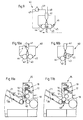
- Fig. 9
- schematisch eine Sprühvorrichtung zum Auftragen des Abstandstoffs,
- Fig. 10a u. 10b
- schematisch die Sprühvorrichtung gemäß Figur 9 zur Veranschaulichung der Unterbrechung eines von der Sprühvorrichtung abgegebenen Sprühkegels,
- Fig. 11a u. 11b
- jeweils ein Schema eines Teils der Druckmaschine mit jeweils unterschiedlich angeordneten Sprühvorrichtungen gemäß Figur 9,
- Fig. 12
- schematisch eine weitere Auftragvorrichtung für den Abstandstoff.
- Fig. 1
- a lacquer layer with wax particles on a printed sheet to explain a first exemplary embodiment of the method according to the invention,
- Fig. 2a
- a wax particle coated with a mixture of water and adhesive or a wax particle in the form of a core from a first wash with a coating made from a second wax with a lower melting point,
- Fig. 2b
- 2a after its fixing on the arch,
- Fig. 3
- wax particles originating from a wax melt and applied to an arch in accordance with a further exemplary embodiment of the method according to the invention,
- Fig. 4
- 1 shows a diagram of part of a printing press for printing sheets with an application device for wax particles assigned to a printing unit cylinder,
- Fig. 5a
- FIG. 2 shows a section of a printing cylinder with a surface structure, shown in greatly enlarged form, in longitudinal section,
- Fig. 5b
- 5a corresponding section in cross section,
- Fig. 6a u. 6b
- schematic representations of a part of the printing press, wherein an application device is arranged differently,
- Fig. 7a u. 7b
- schematically the interaction of a take-up roller and an applicator roller,
- Fig. 8a
- a greatly enlarged longitudinal section of a portion of a roller provided with recesses of an applicator for the spacer,
- Fig. 8b
- 1 shows a diagram of a part of the printing press to illustrate the arrangement of an application device for the spacer material,
- Fig. 9
- schematically a spray device for applying the spacer,
- 10a u. 10b
- schematically the spraying device according to FIG. 9 to illustrate the interruption of a spray cone emitted by the spraying device,
- 11a u. 11b
- each a schematic of a part of the printing press, each with differently arranged spraying devices according to FIG. 9,
- Fig. 12
- schematically another applicator for the spacer.
Zunächst werden mit Bezug auf die Figuren 1 bis 3 verschiedene Möglichkeiten dargelegt, wie der Abstandstoff auf den Bogen aufgebracht und dort fixiert werden kann. Vorzugsweise werden als Abstandstoff kugel- oder tropfenförmige Wachspartikel benutzt, die eine Größe von 5 bis 30 Mikrometern aufweisen. Durch diese Größenwahl ist gewährleistet, daß die Wachspartikel für das bloße menschliche Auge nicht sichtbar sind, das heißt keine Farbveränderungen, Glanzverluste oder andere optische Eigenschaftsänderungen eines Druckprodukts erkennbar sind. Bei den vorzugsweise eingesetzten wachsen handelt es sich insbesondere um Polyethylen-Wachse, die gegenüber den heutigen Pudermaterialien gute Gleiteigenschaften aufweisen, die dadurch entstehen, daß sich bei entsprechender Flächenpressung das Wachs an der Oberfläche der Wachspartikel verflüssigt und einen Schmierfilm bildet.First, with reference to FIGS. 1 to 3, various options are presented for how the spacer material can be applied to the sheet and fixed there. Spherical or teardrop-shaped wax particles with a size of 5 to 30 micrometers are preferably used as the spacer. This choice of size ensures that the wax particles are not visible to the naked human eye, that is to say that no changes in color, loss of gloss or other changes in the optical properties of a printed product are recognizable. The waxes which are preferably used are, in particular, polyethylene waxes which, compared with today's powder materials, have good sliding properties which result from the fact that the wax liquefies at the surface pressure of the wax particles and forms a lubricating film.
Im Beispiel der Figur 1, sind die Wachspartikel 2 einem Dispersionslack 3 beigemischt, der zur Veredelung der Oberfläche des Bogens 1 benutzt wird, beigemischt. Dies geschieht vorzugsweise in einem Verhältnis von 1:10 bis 1:100 (Gewichtsanteile). Das Auftragen der Wachspartikel 2 auf den zuvor mit Farbe 5 bedruckten Bogen 1 erfolgt dann entsprechend über ein Lackwerk. In diesem Fall wirkt die zur Veredelung auf das Papier aufgetragene Lackschicht 3 für die Wachspartikel 2 wie ein Klebstoff, der diese an der Papieroberfläche festhält und im Zuge der Trocknung der Lackschicht auf dem Bogen 1 fixiert.In the example of FIG. 1, the
Mit Bezug auf die Figur 2 wird im folgenden eine weitere Möglichkeit der Fixierung eines Wachspartikels 2 auf einem Bogen 1 erläutert. Die Wachspartikel 2 werden, wie in Figur 2a schematisch gezeigt, mit einer wässrigen Lösung 4 von Klebstoff umhüllt. Der gelöste Klebstoff hat dabei die Aufgabe, den Wachspartikel 2 nach dem Auftragen auf den Bogen 1 auf dem Papier zu fixieren. Dies geschieht dadurch, daß nach dem Auftragen des Wachspartikels 2 die wässrige Lösung 4 verläuft und teilweise in das Papier eindringt, wie es schematisch in Figur 2b gezeigt ist. Somit wird der Wachspartikel 2 punktförmig auf dem Papier fixiert, ohne daß der Klebstoff eine optisch nachteilige Wirkung hat.A further possibility of fixing a
Im Falle einer Verwendung der Wachspartikel 2 In Form eines Pulvers oder als Bestandteil einer wässrigen Suspension ohne Klebstoffanteil besteht im Rahmen der Erfindung eine Möglichkeit zur Fixierung der Wachspartikel 2 auf dem Bogen 1 im Anschluß an den Auftrag auf Letzteren durch eine kurzzeitige Erwärmung des Bogens 1. Dies hat zur Folge, daß ein die Wachspartikel 2 gegebenenfalls umgebender, von der Suspension gebildeter Flüssigkeitsfilm verdampft, und daß die Wachspartikel 2 an der Oberfläche angeschmolzen werden, so daß ein Teil eines jeweiligen Wachspartikels 2 in das Papier abschlägt und die Wachspartikel 2 nach erfolgter Abkühlung an dem Bogen 1 fixiert sind.If the
Die genannte wässrige Suspension kann dabei entweder zum Auftrag auf den Bogen 1 bereitgestellt oder auch durch eine Vermischung der in Pulverform bereitgestellten Wachspartikel 2 mit dem Flüssigkeitsanteil der Suspension während des Auftrags der Wachspartikel 2 gebildet werden. In jedem Falle wird dabei eine Staubbildung vermieden.The aqueous suspension mentioned can either be provided for application to the
Statt einem direkten Auftragen der Wachspartikel 2 auf das Papier kann auch ein indirekter Auftrag erfolgen, indem die Wachspartikel 2 zunächst auf eine Walze aufgebracht und erst dann auf das Papier übertragen werden.Instead of directly applying the
Auf im Rahmen der Erfindung bestehende Möglichkeiten zur Umhüllung eines Wachspartikels 2 mit einer Hülle, wie beispielsweise einer solchen aus der genannten Lösung 4 wird im weiteren Verlauf der Beschreibung noch näher eingegangen.Possibilities within the scope of the invention for enveloping a
Mit Bezug auf die Figur 3 wird eine weitere Möglichkeit dargestellt, wie die Wachspartikel 2 auf das Papier aufgetragen und dort fixiert werden können. In dieser Figur sind schematisch Wachspartikel 2 aufgezeigt, die auf das Papier aufgetragen sind. Ein gewisser Teil des Wachsei der Wachspartikel 2 ist, wie angedeutet, in das Papier eingedrungen, womit die nötige Fixierung erzielt wird. Nachdem die Wachspartikel 2 bei Umgebungstemperatur einen festen Aggregatzustand besitzen und somit nicht in das Papier eindringen können, muß zumindest ein Teil des Wachspartikels in einen viskosen Zustand gebracht werden, so daß dieser Teil in das Papier eindringen kann. Dies kann zum einen durch eine thermische Behandlung nach dem Auftragen der Wachspartikel 2 geschehen. Andererseits ist es jedoch auch möglich, die Wachspartikel 2 vor dem Auftragen als Schmelze zu bevorraten. Dafür ist eine Temperatur von etwa 100 bis 300 °C notwendig. Aus dieser Schmelze werden beispielsweise mittels einer Sprühvorrichtung gemäß Fig. 9 oder 12 wachstropfen gebildet und auf den Bogen 1 gesprüht. Ein zunächst noch geschmolzener Wachstropfen kühlt während dessen ab und verfestigt sich zunehmend. Beim Kontakt des Wachstropfens mit dem Bogen 1 dringt ein Teil des noch nicht vollständig verfestigten Wachses in das Papier ein und bewirkt nach einer weiteren gewissen Abkühlzeit und damit verbundener Verfestigung die Bildung von Wachspartikeln 2 aus den Wachstropfen und deren Fixierung auf dem Bogen 1.With reference to FIG. 3, a further possibility is shown of how the
Bei der Einstellung der zwischen der Sprühvorrichtung und dem Bogen 1 vom wachstropfen zurückgelegten Strecke muß darauf geachtet werden, daß diese zum einen nicht zu lang ist. Dann nämlich kühlt der Wachstropfen zu stark ab und besitzt somit nicht mehr ausreichend fließfähige wachsschmelze, die zur Fixierung notwendig wäre. Ist die zurückgelegte Strecke andererseits zu kurz, so kühlt der Wachstropfen nicht genügend ab, was dazu führt, daß der auf das Papier auftreffende Wachstropfen zu stark zerfließt und somit eine zu geringe Höhe gegenüber der Papieroberfläche aufweist.When setting the distance covered by the wax droplet between the spray device and the
Eine Abwandlung des zuvor beschriebenen Verfahrens besteht darin, daß zum Fixieren auf dem Papier zwar wiederum eine Wachsschmelze benutzt wird, in welcher sich jedoch Wachspartikel in zumindest nahezu festem Aggregatzustand befinden. Dies kann dadurch erreicht werden, daß zwei wachse mit unterschiedlichen Schmelzpunkten verwendet werden, wobei das fixierende Wachs einen niedrigeren Schmelzpunkt aufweist. Die Fixierung der aus der Schmelze vereinzelten und sodann mit einer Umhüllung aus dem Wachs mit niedrigerem Schmelpunkt umgegenen Wachspartikel erfolgt wie im zuvor beschriebenen Beispiel durch Eindringen des geschmolzenen Wachses in das Papier und das anschließende Verfestigen.A modification of the previously described method is that a wax melt is again used for fixing on the paper, but in which wax particles are in at least almost solid aggregate state. This can be achieved by using two waxes with different melting points, the fixing wax having a lower melting point. The wax particles separated from the melt and then encased with a coating made of the wax with a lower melting point are fixed in place, as in the example described above, by penetrating the melted wax into the paper and then solidifying it.
Dies hat den Vorteil, daß mit niedrigeren Temperaturen gearbeitet werden kann als dies der Fall wäre bei der Aufschmelzung des als Abstandstoff dienenden Wachspartikels, der mechanisch wesentlich beständiger sein muß und mithin auch einen höheren Schmelzpunkt aufweist.This has the advantage that it is possible to work at lower temperatures than would be the case when the wax particle serving as a spacer is melted, which has to be mechanically much more stable and therefore also has a higher melting point.
Eine weitere Möglichkeit einer thermischen Fixierung besteht darin, die Wachspartikel 2 mit einem Schmelzkleber zu umhüllen und den aufgetragenen und derart umhüllten Wachspartikel 2 zu erwärmen. Die dazu vorgesehene Temperatur muß gerade dem Schmelzpunkt des Schmelzklebers entsprechen, der dann zur Fixierung dient. Der Schmelzpunkt des Wachspartikels 2 sollte jedoch nicht erreicht werden, um ein Aufschmelzen desselben zu vermeiden.Another possibility of a thermal fixation is to coat the
Statt die Wachspartikel 2 mit einem Schmelzkleber zu umhüllen, kann hierzu ein wasserlöslicher Klebstoff benutzt werden. Dieser Klebstoff kann dann durch gezieltes Befeuchten auf der Oberfläche des Bogens aktiviert werden. Durch das Wasseraufnahmevermögen des den Bogen bildenden Papiers wird dem Klebstoff das Wasser wieder entzogen und die Wachspartikel sind dann auf der Oberfläche des Bogens fixiert.Instead of enveloping the
Mit Bezug auf die Figuren 4 bis 12 werden im folgenden verschiedene Vorrichtungen zur Durchführung des erfindungsgemäßen Verfahrens und dessen Ausführungsarten beschrieben.Various devices for carrying out the method according to the invention and its embodiments are described below with reference to FIGS. 4 to 12.
Figur 4 ist ein Schema eines Teils einer Druckmaschine zum Bedrucken der Bogen 1. Insbesondere ist ein Druckwerk 25 und ein daran anschließender Ausleger 21 gezeigt. Das Druckwerk 25 umfaßt einen Druckzylinder 12, einen Gummituchzylinder 15 und einen Plattenzylinder 16, um den ein Farbwerk 18 und im Falle eines Betriebs der Druckmaschine im Naßoffsetverfahren ein Feuchtwerk 17 gruppiert sind. Ein jeweiliger Bogen 1 wird dem Druckzylinder 12 mittels eines Bogenführungszylinders 19 zugeführt. Dem Druckzylinder 12 ist eine Auftragvorrichtung 11 mit einer Auftragwalze 13 und einer Aufnahmewalze 14 zugeordnet, welche aus einem Vorratsbehälter 24 eine darin bereitgestellte Suspension aus Wasser, Klebstoff und Abstandstoffpartikeln 2 aufnimmt.FIG. 4 is a diagram of a part of a printing press for printing on the
Um die Abstandstoffpartikel 2 erfindungsgemäß punktuell auf den Bogen 1 aufzutragen, besitzt bei einer ersten Variante der Auftragvorrichtung 11 mit einer Auftragwalze 13 mit glatter Mantelfläche der Druckzylinder 12 gemäß Figur 5a eine Mantelfläche mit kugelkalottenförmigen Erhebungen und hierzwischen liegenden, Vertiefungen 31 bildenden Tälern, mittels welchen den in der Suspension enthaltenen Abstandstoffpartikeln 2 deren gewünschte Verteilung aufgezwungen wird. Beim Kontakt des Druckzylinders mit dem Papier ist die Schichtdicke von Wasser und Klebstoff in den nicht vertieften Bereichen der Mantelfläche des Druckzylinders 12 zu gering, um eine nennenswerte übertragung von Klebstoff durch Flüssigkeitsspaltung auf das Papier zu bewirken. Die Abstandstoffpartikel 2 in den Vertiefungen 31 haften durch den wasserlöslichen Klebstoff am Papier. Beim Herauslösen der Abstandstoffpartikel 2 aus den Vertiefungen 31 infolge des Abschälens des Bogens 1 vom Druckzylinder 12 wird im allgemeinen nur ein Teil einer aus Wasser und Klebstoff gebildeten Flüssigkeit 6 vom jeweiligen Abstandstoffpartikel 2 in Form einer Umhüllung desselben mitgenommen, wie dies schematisch in der Figur 5b gezeigt ist. Aus dem in der Vertiefung 31 zurückbleibenden Teil der Flüssigkeit 6 ergeben sich jedoch keine verfahrenstechnischen Nachteile.In order to selectively apply the
Die Auftragwalze 13 kann entweder den Durchmesser des Druckzylinders 12 und einen entsprechenden Ausschnitt für die Greifer des Druckzylinders 12 aufweisen. Sie kann aber auch mit kleinerem Durchmesser ausgebildet werden und beispielsweise mittels einer Kurvensteuerung zu- und abgestellt werden, um im abgestellten Zustand den Greifern des Druckzylinders 12 auszuweichen.The
Die insoweit erläuterte Zuordnung der Auftragvorrichtung 11 zum Druckzylinder 12 bewirkt, daß die Abstandstoffpartikel 2 nicht auf die bedruckte Seite des Bogens 1 sondern auf dessen Rückseite aufgebracht werden. Auf die Funktion der Abstandstoffpartikel 2 als Abstandhalter hat dies jedoch keinen Einfluß.The assignment of the
Die Figuren 6a und 6b zeigen jeweils ein Schema eines Teils einer Druckmaschine, die der in Figur 4 gezeigten im wesentlichen entspricht. Im Unterschied zu dem in Figur 4 gezeigten Ausführungsbeispiel ist die Auftragvorrichtung 11 jedoch nicht dem Druckzylinder 12 sondern dem Gummituchzylinder 15 zugeordnet, wobei sie gemäß Fig. 6a so bezüglich diesem plaziert ist, daß zunächst Farbe und anschließend die Abstandstoffpartikel 2 auf den Gummituchzylinder 15 übertragen werden. Diese Reihenfolge ist bei der Anordnung gemäß Fig. 6b vertauscht.FIGS. 6a and 6b each show a diagram of a part of a printing press which essentially corresponds to that shown in FIG. 4. In contrast to the exemplary embodiment shown in FIG. 4, the
Nachdem der Gummituchzylinder 15 eine im wesentlichen glatte Oberfläche besitzt, ist bei den Ausführungsbeispielen gemäß Fig. 6a und 6b die Mantelfläche der Auftragwalze 13 der Auftragvorrichtung 11 mit einer bestimmten Oberflächenstruktur versehen, um die Abstandstoffpartikel 2 punktuell und mit der bereits erläuterten gewünschten Verteilung mittels eines auf den Gummituchzylinder 15 aufgespannten Gummituchs auf das Papier aufzubringen.After the
In vorteilhafter Ausgestaltung ist die Mantelfläche der Auftragwalze 13 mit Näpfchen 27 versehen. Diese Näpfchen 27 sind so dimensioniert, daß gerade ein Abstandstoffpartikel 2 mit etwas wassergelöstem Kleber aufgenommen werden kann. Vorzugsweise sind die Oberflächen der Näpfchen 27 hydrophil, während die übrigen Flächenanteile der Mantelfläche der Auftragwalze 13, die mit dem Gummituch des Gummituchzylinders 15 in Kontakt kommen, beispielsweise durch eine spezielle Beschichtung bevorzugt eine hydrophobe Eigenschaft haben. Wie bereits im Zusammenhang mit Figur 4 beschrieben, werden die Abstandstoffpartikel 2 beziehungsweise die Suspension mittels der Aufnahmewalze 14 aus dem Vorratsbehälter 24 entnommen und der Auftragwalze 13 zugeführt. Unterstützt durch das beschriebene Annahmeverhalten der Mantelflächenbereiche der Auftragwalze 13 füllen sich die Näpfchen 27 mit den Abstandstoffpartikeln 2 beziehungsweise mit der Suspension, während die nicht vertieften Mantelflächenbereiche der Auftragwalze 13 an einer übertragung der Abstandstoffpartikel 2 unbeteiligt bleiben. Die gewünschte Verteilung der Abstandstoffpartikel 2 ist hierbei durch eine entsprechende Verteilung der Näpfchen 27 in der Mantelfläche der Auftragwalze 13 bestimmt.In an advantageous embodiment, the lateral surface of the
Vorzugsweise ist die Aufnahmewalze 14 mit einer elastischen Mantelfläche versehen. Der Anpressdruck zwischen der Auftragwalze 13 und der Aufnahmewalze 14 ist dabei so eingestellt, daß bei einer Näpfchenfüllung ohne Abstandstoffpartikel 2 die meiste Flüssigkeit wieder aus dem Näpfchen herausgequetscht wird. Dieser Vorgang ist schematisch in den Figuren 7a und 7b verdeutlicht. Figur 7a zeigt den Fall einer Näpfchenfüllung ohne Abstandstoffpartikel 2. Durch die Wahl einer elastischen Mantelfläche der Aufnahmewalze 14 wölbt sich der über dem Näpfchen 27 der Auftragwalze 13 liegende Bereich der Mantelfläche der Aufnahmewalze 14 in das Näpfchen 27 hinein. Dabei hängt der Grad der Wölbung zum einen von der Elastizität der Mantelfläche und zum anderen von dem Anpressdruck zwischen Auftragwalze 13 und Aufnahmewalze 14 ab. Diese Wölbung bewirkt, daß eine gegebenenfalls im Näpfchen 27 befindliche Flüssigkeit, insbesondere wasserlöslicher Kleber, herausgequetscht wird, wenn sich kein Abstandstoffpartikel 2 im Näpfchen 27 befindet. Damit wird verhindert, daß im Wasser gelöster Klebstoff ohne Abstandstoffpartikel 2 übertragen wird und dadurch das Druckprodukt optisch beeinträchtigt wird.The
Figur 7b zeigt dagegen den Fall, daß sich ein Abstandstoffpartikel 2 in einem der Näpfchen 27 der Auftragwalze 13 befindet. Dabei sorgt der Abstandstoffpartikel 2 dafür, daß sich die elastische Mantelfläche der Aufnahmewalze 14 zu deren Achse hin wölbt, wie dies schematisch in der Figur angedeutet ist. Bei der Wahl des Anpreßdrucks beziehungsweise des Materials zur Bildung der elastischen Mantelfläche der Aufnahmewalze 14 ist darauf zu achten, daß sich bei der bevorzugten Verwendung von Abstandstoffpartikeln 2 in Form von Wachspartikeln ein jeweiliger Wachspartikel 2 beim Kontakt mit der Auftragwalze 13 nicht übermäßig deformiert.FIG. 7b, on the other hand, shows the case in which a
Um ein betriebsmäßiges Füllen der Näpfchen 27 mit einem jeweiligen Wachspartikel 2 zu erleichtern, kann der Antrieb der beiden Walzen 13, 14 so konzipiert sein, daß vorzugsweise eine kleine Relativgeschwindigkeit zwischen diesen beiden Walzen herrscht, wobei die Relativgeschwindigkeit veränderbar ist. Der Vorteil dabei liegt darin, daß durch die Reibung zwischen den beiden Walzenmantelflächen die Wachspartikel 2 Leichter in die Näpfchen 27 gelangen.In order to facilitate the operational filling of the
Die in der Figur 8b gezeigte Auftragvorrichtung 11' ist gegenüber der zuvor beschriebenen Auftragvorrichtung leicht modifiziert. Die von der Aufnahmewalze 14 aufgenommene Suspension wird hierbei nicht unmittelbar an die Auftragwalze 13 übertragen, sondern zunächst an eine Zwischenwalze 30, von der aus sodann die Weitergabe an die Auftragwalze 13 erfolgt.The application device 11 'shown in FIG. 8b is slightly modified compared to the application device described above. The suspension taken up by the take-up
Anstelle einer mittels der Näpfchen 27 gebildeten Oberflächenstruktur kann die Zwischenwalze 30 - wie im übrigen auch die Auftragwalze 13 - in Umfangsrichtung der Mantelfläche oder in einer zur Umfangsrichtung geneigten Richtung verlaufende Nuten oder Rillen 32 aufweisen,
wie dies schematisch in Figur 8a dargestellt ist. Die Funktionsweise der Aufnahme der Wachspartikel 2 und deren Weitergabe an die Auftragwalze 13 beziehungsweise an den Gummituchzylinder 15 entspricht dabei im wesentlichen derjenigen der mit Näpfchen 27 versehenen Mantelfläche.
Die gewünschte Verteilung der Wachspartikel 2 wird hierbei durch geeignete Wahl der Abstände zwischen den Rillen 32 und einer sodann gegebenenfalls von jender der Auftragwalze 13 abweichenden Umfangsgeschwindigkeit der Zwischenwalze 30 erzielt. Besitzt beispielsweise
die Auftragwalze 13 die Umfangsgeschwindigkeit des Gummituchzylinders 15 und die Zwischenwalze 30 eine geringere Umfangsgeschwindigkeit, so werden die in den einzelnen Rillen 32 der Zwischenwalze 30 liegenden Wachspartikel 2 unter einem Abstand auf die Auftragwalze 13 übertragen, der gegenüber einem Abstand zwischen den in den Rillen 32 befindlichen Wachspartikeln 2 vergrößert ist.Instead of a surface structure formed by means of the
as shown schematically in Figure 8a. The way in which the
The desired distribution of the
the
Wie bereits zuvor erwähnt, kann die Auftragvorrichtung 11 beispielweise auch vor dem Plattenzylinder 16 liegen oder dem Druckzylinder 12 zugeordnet sein.As already mentioned above, the
Zur Erzielung der gewünschten Verteilung der Wachspartikel 2 ist eine mittels Vertiefungen 31 in Form von Tälern zwischen kugelkalottenförmigen Erhebungen, Näpfchen 27 oder Rillen 32 gebildete Oberflächenstruktur grundsätzlich lediglich an einer der an der übertragung der Wachspartikel 2 beteiligten Mantelflächen erforderlich. Es kann jedoch durchaus vorteilhaft sein, wenn auf dem Weg der Wachspartikel 2 aus dem Vorratsbehälter 24 zur Mantelfläche des Druckzylinders 12 bzw. des Gummituchzylinders 15 zwei mit einer jeweiligen Oberflächenstruktur versehene Mantelflächen aufeinanderfolgen, wie beispielsweise auf dem Weg zum Gummituchzylinder 15 eine mit den Rillen 32 versehene Mantelfläche der Zwischenwalze 30 und eine mit den Näpfchen 27 versehene Mantelfläche der Auftragwalze 13 oder auch eine mit Rillen 32 versehene Mantelfläche der Auftragwalze 13, wobei die Rillen von Zwischenwalze 30 und Auftragwalze 13 unterschiedliche Neigung gegenüber der jeweiligen Walzenlängsachse aufweisen, oder wie beispielsweise auf dem Weg zum Druckzylinder 12 eine mit den Rillen 32 versehene Mantelfläche der Auftragwalze 13 und eine mit den Vertiefungen 31 in Form der Täler zwischen den kugelkalottenförmigen Erhebungen versehene Mantelfläche des Druckzylinders 12.In order to achieve the desired distribution of the
Wie bereits erwähnt, kann der Auftrag der Wachspartikel 2 anstatt mittels der Auftragwalze 13 der Auftragvorrichtung 11 bzw. 11' auch mittels einer Sprühvorrichtung 40 erfolgen, mittels welcher eine mittels des Abstandsstoffs gebildete Sprühflüssigkeit versprüht wird und welche in der Druckmaschine so angeordnet werden kann, daß der Bogen 1 selbst oder ein damit kontaktierender Druckzylinder besprüht wird. Die Sprühflüssigkeit kann hierbei in Form der genannten Schmelze des als Abstandstoff benutzten Wachses oder in Form der genannten, die Wachspartikel 2 und einen in Wasser gelösten Klebstoff enthaltenden wässrigen Suspension vorliegen.As already mentioned, instead of using the
Allgemein umfaßt eine solche Sprühvorrichtung 40 Düsen 41, denen einerseits Druckluft über eine entsprechende Druckluftleitung 48 und andererseits die Sprühflüssigkeit über eine Sprühstoffleitung 49 zugeführt werden. Die über die Sprühstoffleitung 49 zugeführte Sprühflüssigkeit wird aus einem Vorratsbehälter 46 mittels einer Pumpe 47 abgesaugt. Zur Begrenzung eines an einer jeweiligen Düse 41 entstehenden Sprühkegels ist eine vorzugsweise aus zwei Walzen 42, 43 gebildete Begrenzungsvorrichtung vorgesehen, wie dies in Figur 9 gezeigt ist. Die Anordnung der beiden Walzen 42, 43 erfolgt derart, daß sich ein Spalt zwischen ihnen ausbildet, durch den ein Teil des Sprühkegels hindurchtreten kann. Um zu verhindern, daß an den Mantelflächen der Walzen 42 und 43 abgelagerte Reste der Sprühflüssigkeit den Spalt verstopfen, werden die beiden Walzen 42, 43 gedreht und abgerakelt. Dabei wird die Drehrichtung so gewählt, daß sich die beiden Mantelflächen im Bereich des Spalts entgegengesetzt zur Sprührichtung drehen.In general, such a
Eine Reinigungsvorrichtung für die Walzen 42, 43, die in der in Figur 9 gezeigten Anordnung aus Rakeln 44 und 45 besteht, reinigt die Walzen 42, 43 von anhaftendem Resten der Sprühflüssigkeit und führt diese in den Vorratsbehälter 46 zurück.A cleaning device for the
Die den Spalt zwischen den Walzen 42 und 43 passierende Menge der Sprühflüssigkeit kann neben der Einstellung von Sprühparametern, wie Druckluftmenge oder Menge der der Düse zugeführten Sprühflüssigkeit, durch die Breite des genannten Spalts gesteuert werden. Hierzu sind die Walzen 42, 43 zueinander verstellbar angeordnet. Neben einer parallelen Verschiebung der beiden Walzen 42 und 43 zueinander, die eine konstante Breite des Spalts über die gesamte Länge der Walzen 42 und 43 ergibt, ist auch denkbar, durch eine entsprechende Verschiebung einer der Walzen 42 und 43 eine unterschiedliche Breite des Spalts über die Druckmaschinenbreite einzustellen. Zur Abschaltung beziehungsweise Unterbrechung des Sprühkegels gibt es außer der Abschaltung der Pumpe 47 beziehungsweise der Druckluft 48 die in Figur 10a gezeigte Möglichkeit, die Düse 41 so zu schwenken, daß der von dieser abgegebene Sprühkegel nicht auf den Spalt trifft. Hierbei wird jedoch zweckmäßigerweise sichergestellt, daß die Sprühflüssigkeit in den Vorratsbehälter 46 gelangt. In dem in Figur 9 gezeigten Beispiel wird dies dadurch erreicht, daß sich die Düse 41 innerhalb des Vorratsbehälters 46 befindet und nach dem Schwenken beispielsweise auf eine Seitenwand desselben gerichtet ist. Eine weitere Möglichkeit besteht darin, den von den beiden Walzen 42, 43 gebildeten Spalt zu schließen, indem diese aufeinander zu bewegt werden, wie dies schematisch in Figur 10b gezeigt ist. Dabei ist neben einer Parallelverschiebung einer der Walzen 42, 43 auch eine Verschiebung in eine schräg nach oben oder schräg nach unten gerichtete Lage möglich.The amount of the spray liquid passing through the gap between the
Durch entsprechendes unterbrechen des Sprühkegels ist insbesondere erreichbar, daß beispielsweise ein Besprühen von Greifereinrichtungen verhindert wird, mittels welcher die Bogen 1 transportiert werden.By correspondingly interrupting the spray cone, it can be achieved in particular that, for example, spraying of gripper devices by means of which the
Ebenso wie im Falle der Verwendung der beschriebenen Auftragvorrichtung 11, bestehen im Falle der Verwendung von Sprühvorrichtungen 40 verschiedene Anordnungsmöglichkeiten für diese in der Druckmaschine. Zwei Möglichkeiten davon sind in den Figuren 11 a und 11b gezeigt. In der Figur 11a ist die Sprühvorrichtung 40 so angeordnet, daß die Sprühflüssigkeit auf die bedruckte Seite des Bogens 1 trifft. In Abbildung 11b dagegen ist eine Sprühvorrichtung 40' nach dem Funktionsprinzip der Sprühvorrichtung 40 auf einen Bereich des Druckzylinders 12 gerichtet, auf den sich im weiteren Verlauf der Drehung desselben der Bogen 1 auflegt. Damit erfolgt der Auftrag der Sprühflüssigkeit indirekt über den Druckzylinder 12 auf die Rückseite des Bogens 1. Selbstverständlich sind auch andere denkbare Anordnungen möglich.Just as in the case of the use of the
Figur 12 zeigt schematisch eine weitere Ausgestaltung einer Sprühvorrichtung. Im Gegensatz zu der zuvor beschriebenen Sprühvorrichtung 40 wird hier nicht Druckluft sondern ein elektrisches Feld zur Ausbringung der Sprühflüssigkeit benutzt.Figure 12 shows schematically a further embodiment of a spray device. In contrast to the
Die in Fig. 12 wiedergegebene Sprühvorrichtung 60 umfaßt eine Düse 51, die aus einem Vorratsbehälter 55 mit der Sprühflüssigkeit versorgt ist. Die Düse 51 ist im gezeigten Beispiel radial auf den Druckzylinder 12 ausgerichtet. An eine im wesentlichen senkrecht zur vorgesehenen Ausrichtung der Düse 51 stehende Platte 53 einerseits und an den Druckzylinder 12 andererseits ist eine elektrische Spannung angelegt, welche ein elektrisches Feld aufbaut.The spray device 60 shown in FIG. 12 comprises a
Die im Vorratsbehälter 55 enthaltene Sprühflüssigkeit ist vorzugsweise ein Stoffgemisch 56 aus Wachspartikeln 2 in einer Klebstofflösung. Durch das elektrische Feld werden die Wachspartikel 2 und daran haftender Klebstoff 58 beschleunigt, der letztlich für die nötige Fixierung der Wachspartikel 2 auf dem Papier des Bogens 1 sorgt.The spray liquid contained in the
Diese Vorrichtung 60 kann vorzugsweise an den gleichen Stellen in der Druckmaschine wie die vorgenannten Auftragvorrichtungen 11, 11', 40, 40' angeordnet werden. Quer zur Bogenlaufrichtung wird ein Düsenarray über die gesamte Breite des Bogens 1 angeordnet. Der punktuelle Auftrag der Wachspartikel 2 sowie eine Steuerung der Auftragsmenge erfolgt durch Ein- und Ausschalten der angelegten Spannung.This device 60 can preferably be arranged at the same locations in the printing press as the
Claims (25)
gekennzeichnet durch
die Schritte:
Bereitstellen eines zumindest bei Umgebungstemperatur festen Abstandstoffs,
punktuelles Auftragen einzelner aus dem Abstandstoff gebildeter Abstandstoffpartikel (2) auf eine Oberfläche des Bogens (1) und Fixieren der aufgetragenen Abstandstoffpartikel (2) auf dem Bogen (1).Process for applying a spacer material to sheets which are printed on and then stacked by means of a printing machine using printing unit cylinders,
marked by
the steps:
Providing a spacer that is solid at least at ambient temperature,
selective application of individual spacer particles (2) formed from the spacer to a surface of the sheet (1) and fixing the applied spacer particles (2) on the sheet (1).
dadurch gekennzeichnet,
daß die Abstandstoffpartikel (2) eine Größe von 5 bis 30 Mikrometer aufweisen und regellos in einem gegenseitigen mittleren Abstand von 50 bis 400 Mikrometer auf den Bogen (1) derart aufgebracht werden, daß auf untereinander gleichen Teilflächen der Oberfläche des Bogens (1) eine zumindest nahezu gleiche Anzahl von Abstandstoffpartikeln vorhanden ist.Method according to claim 1,
characterized by
that the spacer particles (2) have a size of 5 to 30 micrometers and are randomly applied at a mutual mean distance of 50 to 400 micrometers to the sheet (1) in such a way that at least one of the same partial areas of the surface of the sheet (1) almost the same number of spacer particles is present.
dadurch gekennzeichnet,
daß die Abstandstoffpartikel (2) zusammen mit einer Farbe oder einem Lack auf den Bogen (1) aufgebracht und anschließend unter Trocknung auf dem Bogen (1) fixiert werden.Method according to claim 1,
characterized by
that the spacer particles (2) are applied together with a paint or varnish to the sheet (1) and then fixed while drying on the sheet (1).
dadurch gekennzeichnet,
daß die Abstandstoffpartikel (2) im Verhältnis 1:10 bis 1:100 (Gewichtsanteile) der Farbe beziehungsweise dem Lack zugemischt werden.Method according to claim 3,
characterized by
that the spacer particles (2) are mixed in a ratio of 1:10 to 1: 100 (parts by weight) of the paint or lacquer.
dadurch gekennzeichnet,
daß dem Abstandstoff Wasser und ein wasserlöslicher Kleber beigemischt wird, und daß dieses Gemisch in Form einzelner Abstandstoffpartikel (2) mit einer Umhüllung aus Wasser und Kleber auf den Bogen (1) aufgebracht wird.Method according to claim 1,
characterized by
that water and a water-soluble adhesive are added to the spacer, and that this mixture is applied to the sheet (1) in the form of individual spacer particles (2) with a coating of water and adhesive.
dadurch gekennzeichnet,
daß die Abstandstoffpartikel (2) indirekt über zumindest einen Druckwerkszylinder (12, 15) oder direkt auf den Bogen (1) aufgebracht werden.Method according to claim 1,
characterized by
that the spacer particles (2) are applied indirectly via at least one printing unit cylinder (12, 15) or directly to the sheet (1).
dadurch gekennzeichnet,
daß der Abstandstoff in Form von Abstandstoffpartiklen (2) mit einer Umhüllung aus wasserlöslichem Klebstoff bereitgestellt wird, und daß beim Auftragen der Abstandstoffpartikel (2) der Klebstoff durch Befeuchten aktiviert wird, um die Abstanndstoffpartikel auf dem Bogen (1) zu fixieren.Method according to claim 1,
characterized by
that the spacer in the form of spacer particles (2) is provided with a coating of water-soluble adhesive, and that when the spacer particles (2) are applied, the adhesive is activated by moistening in order to fix the spacer particles on the sheet (1).
dadurch gekennzeichnet,
daß als Abstandstoff Wachs verwendet wird, das in Form von Wachspartikeln (2) auf den Bogen (1) aufgetragen wird.Method according to claim 1,
characterized by
that wax is used as a spacer, which is applied in the form of wax particles (2) to the sheet (1).
dadurch gekennzeichnet,
daß die Wachspartikel (2) aus einer Schmelze gewonnen werden, wobei zum Auftragen Tropfen daraus vereinzelt werden, und daß die Fixierung der Wachspartikel (2) durch teilweises Eindringen des Tropfens in den Bogen (1) oder Festkleben auf der Oberfläche des Bogens (1) und durch anschließendes Abkühlen und Verfestigen erreicht wird.A method according to claim 8,
characterized by
that the wax particles (2) are obtained from a melt, drops from which are separated for application, and that the wax particles (2) are fixed by partial penetration of the drop into the sheet (1) or sticking to the surface of the sheet (1) and is achieved by subsequent cooling and solidification.
gekennzeichnet dadurch
eine Ausbildung eines jeweiligen der Wachspartikel (2) in Form eines Kerns (2') aus einem ersten Wachs und einer den Kern (2') umgebenden Umhüllung (4') aus einem zweiten Wachs mit einem gegenüber dem ersten Wachs niedrigeren Schmelzpunkt.A method according to claim 8,
characterized by it
a formation of a respective one of the wax particles (2) in the form of a core (2 ') from a first wax and a covering (4') surrounding the core (2 ') from a second wax with a melting point lower than that of the first wax.
dadurch gekennzeichnet,
daß die Wachspartikel (2) in Form von Pulver bereitgestellt werden, und daß das Fixieren durch kurzzeitige thermische Behandlung erfolgt.A method according to claim 8,
characterized by
that the wax particles (2) are provided in the form of powder, and that the fixation is carried out by brief thermal treatment.
dadurch gekennzeichnet,
daß eine die Wachspartikel (2) enthaltende wässrige Suspension bereitgestellt wird und die Wachspartikel (2) durch kurzzeitige thermische Behandlung auf dem Bogen (1) fixiert werden.A method according to claim 8,
characterized by
that an aqueous suspension containing the wax particles (2) is provided and the wax particles (2) are fixed on the sheet (1) by brief thermal treatment.
gekennzeichnet dadurch
eine Auftragvorrichtung (11) zum punktuellen Auftragen von aus einem Abstandstoff gebildeten Abstandstoffpartikeln (2) auf den Bogen (1) mit einem Behälter (24) zur Bevorratung des Abstandstoffs und mit Walzen in Form einer Aufnahmewalze (14) zur Aufnahme des Abstandstoffs aus dem Behälter (24) und einer dieser zugeordneten Auftragwalze (13), wobei der Druckzylinder (12) oder die Auftragwalze (13) eine Mantelfläche mit einer zur punktuellen Aufbringung der Abstandstoffpartikel (2) geeigneten, mittels Vertiefungen (31, 27, 32) gebildeten Oberflächenstruktur aufweist.Printing machine for printing sheets (1), in particular with an inking unit (18), and with printing unit cylinders in the form of a plate cylinder (16), a blanket cylinder (15) and a printing cylinder (12),
characterized by it
an application device (11) for the selective application of spacer particles (2) formed from a spacer onto the sheet (1) with a container (24) for storing the spacer and with rollers in the form of a pick-up roller (14) for receiving the spacer from the container (24) and an applicator roller (13) assigned to them, the pressure cylinder (12) or the applicator roller (13) having an outer surface with a surface structure which is suitable for punctual application of the spacer particles (2) and is formed by means of depressions (31, 27, 32) .
gekennzeichnet dadurch
eine Auftragvorrichtung (11') zum punktuellen Auftragen von aus einem Abstandstoff gebildeten Abstandstoffpartiklen (2) auf den Bogen (1) mit einem Behälter (24) zur Bevorratung des Abstandstoffs und mit Walzen in Form einer Aufnahmewalze (14) zur Aufnahme des Abstandstoffs aus dem Behälter (24), einer Auftragwalze (13) zum punktuellen Auftragen der Abstandstoffpartikel (2) auf den Gummituchzylinder (15) bzw. den Druckzylinder (12) und einer zwischen der Aufnahmewalze (14) und der Auftragwalze (13) angeordneten Zwischenwalze (30), wobei wenigstens eine der Mantelflächen von Druckzylinder (12), Auftragwalze (13) und Zwischenwalze (30) eine zum punktuellen Auftrag der Abstandstoffpartikel (2) geeignete, mittels Vertiefungen (31, 27, 32) gebildete Oberflächenstruktur aufweist.Printing machine for printing sheets (1), in particular with an inking unit (18), as well as with printing unit cylinders in the form of a plate cylinder (16), a blanket cylinder (15) and a printing cylinder (12)
characterized by it
an application device (11 ') for the selective application of spacer particles (2) formed from a spacer onto the sheet (1) with a container (24) for storing the spacer and with rollers in the form of a pick-up roller (14) for receiving the spacer from the Container (24), an application roller (13) for the selective application of the spacer particles (2) to the blanket cylinder (15) or the impression cylinder (12) and an intermediate roller (30) arranged between the pick-up roller (14) and the application roller (13) wherein at least one of the lateral surfaces of the pressure cylinder (12), applicator roller (13) and intermediate roller (30) has a surface structure which is suitable for the punctual application of the spacer particles (2) and is formed by means of depressions (31, 27, 32).
dadurch gekennzeichnet,
daß die Auftragwalze (13) dem Druckzylinder (12) zugeordnet ist, und daß der Druckzylinder (12) die Oberflächenstruktur aufweist.Printing machine according to claim 13 or 14,
characterized by
that the applicator roller (13) is assigned to the impression cylinder (12) and that the impression cylinder (12) has the surface structure.
dadurch gekennzeichnet,
daß die Oberflächenstruktur des Druckzylinders (12) kugelkalottenförmige Erhebungen aufweist und hierzwischen liegende, die Vertiefungen (31) darstellende Täler so dimensoniert sind, daß darin wenigstens ein Abstandstoffpartikel (2) aufgenommen werden kann.Printing machine according to claim 13 or 14,
characterized by
that the surface structure of the pressure cylinder (12) has spherical dome-shaped elevations and valleys between them which represent the depressions (31) are dimensioned such that at least one spacer particle (2) can be accommodated therein.
dadurch gekennzeichnet,
daß die Auftragwalze (13) dem Druckzylinder (12) oder dem Gummituchzylinder (15) zugeordnet ist, und daß die Vertiefungen in der Mantelfläche der Auftragwalze (13) vorgesehen und mittels an die Größe der Abstandstoffpartikel (2) angepaßten Näpfchen (27) oder zumindest im wesentlichen in Umfangsrichtung der Mantelfläche verlaufenden Rillen (32) gebildet sind.Printing machine according to claim 13 or 14,
characterized by
that the application roller (13) is assigned to the impression cylinder (12) or the blanket cylinder (15), and that the depressions are provided in the lateral surface of the application roller (13) and are adapted to the size of the spacer particles (2) or at least grooves (32) extending essentially in the circumferential direction of the lateral surface are formed.
dadurch gekennzeichnet,
daß die Auftragwalze (13) dem Druckzylinder (12) oder dem Gummituchzylinder (15) zugeordnet ist und die Vertiefungen in den Mantelflächen der Auftragwalze (13) bzw. der Zwischenwalze (30) mittels an die Größe der Abstandstoffpartikel (2) angepaßten Näpfchen (27) oder zumindest im wesentlichen in Umfangsrichtung der Mantelflächen verlaufenden Rillen (32) gebildet sind.Printing machine according to claim 14,
characterized by
that the applicator roller (13) is assigned to the impression cylinder (12) or the blanket cylinder (15) and the depressions in the lateral surfaces of the applicator roller (13) or the intermediate roller (30) by means of cups (27) adapted to the size of the spacer particles (2) ) or at least substantially grooves (32) extending in the circumferential direction of the lateral surfaces.
dadurch gekennzeichnet,
daß die Vertiefungen (27, 32) eine hydrophile Oberfläche aufweisen und von hydrophoben Mantelflächenbereichen umgeben sind.Printing machine according to claim 13 or 14,
characterized,
that the depressions (27, 32) have a hydrophilic surface and are surrounded by hydrophobic surface areas.
dadurch gekennzeichnet,
daß die Aufnahmewalze (14) eine elastische Mantelfläche aufweist.Printing machine according to claim 13 or 14,
characterized by
that the pickup roller (14) has an elastic jacket surface.
gekennzeichnet dadurch
eine Differenz der Umfangsgeschwindigkeiten der Walzen der Auftragvorrichtung (11 bzw. 11')Printing machine according to claim 13 or 14,
characterized by it
a difference in the peripheral speeds of the rollers of the application device (11 or 11 ')
gekennzeichnet dadurch
eine Sprühvorrichtung (40), welche eine mittels des Abstandstoffs gebildete Sprühflüssigkeit auf einen der Druckwerkszylinder (12, 15) oder den Bogen (1) aufsprüht, mit einem Vorratsbehälter (46) für die Sprühflüssigkeit, einer Düse (41), einer Pumpe (47), welche die Sprühflüssigkeit aus dem Vorratsbehälter (46) der Düse (41) zuführt, zwei zueinander parallel angeordneten, einen Spalt bildenden Walzen (42, 43), welche einen aus der Düse (41) austretenden Sprühkegel begrenzen, und mit einer den beiden Walzen (42, 43) zugeordneten Reinigungsvorrichtung (44, 45), die an den Walzen (42, 43) haftende Reste der Sprühflüssigkeit von den Walzen (42, 43) entfernt und in den Vorratsbehälter (46) zurückführt.Printing machine for printing sheets (1), in particular with an inking unit (18), and with printing unit cylinders in the form of a plate cylinder (16), a blanket cylinder (15) and a printing cylinder (12),
characterized by it
a spray device (40) which sprays a spray liquid formed by means of the spacer onto one of the printing unit cylinders (12, 15) or the sheet (1), with a reservoir (46) for the spray liquid, a nozzle (41), a pump (47 ), which supplies the spray liquid from the reservoir (46) to the nozzle (41), two mutually parallel, gap-forming rollers (42, 43) which delimit a spray cone emerging from the nozzle (41), and one of the two Cleaning device (44, 45) associated with rollers (42, 43), which removes residues of the spray liquid adhering to the rollers (42, 43) from the rollers (42, 43) and returns them to the storage container (46).
dadurch gekennzeichnet,
daß die Düse (41) schwenkbar ist, wobei durch Schwenken der Düse (41) das Auftragen der Sprühflüssigkeit unterbrochen werden kann.Printing machine according to claim 22,
characterized by
that the nozzle (41) is pivotable, the application of the spray liquid can be interrupted by pivoting the nozzle (41).
dadurch gekennzeichnet,
daß die Walzen (42, 43) der Sprühvorrichtung (40) parallel zueinander verschiebbar angeordnet sind, um den zwischen ihnen Liegenden Spalt schließen zu können und somit das Auftragen der Sprühflüssigkeit zu unterbrechen.Printing machine according to claim 2,
characterized by
that the rollers (42, 43) of the spray device (40) are arranged so as to be displaceable parallel to one another in order to be able to close the gap between them and thus to interrupt the application of the spray liquid.
gekennzeichnet dadurch
eine Sprühvorrichtung mit einer auf einen Druckwerkszylinder, insbesondere den Druckzylinder (12) gerichteten Düse (51), einem Behälter (55) zur Bevorratung eines gegebenenfalls eine Mischung mit einem Klebstoff bildenden Abstandstoffs und einer leitfähigen Platte (53), die derart angeordnet ist, daß sich die öffnung der Düse (51) im Raum zwischen der Platte (53) und dem Druckwerkszylinder (12) befindet, wobei zwischen Druckwerkszylinder (12) und der Platte (53) ein elektrisches Feld ausbildbar ist und bei Aktivieren dieses elektrischen Feldes Partikel des Abstandsstoffs bzw. der Mischung aus der Düse zum Druckwerkszylinder (12) gezogen werden.Printing machine for printing sheets (1), in particular with an inking unit (18), and with printing unit cylinders in the form of a plate cylinder (16), a blanket cylinder (15) and a printing cylinder (12),
characterized by it
a spraying device with a nozzle (51) directed towards a printing unit cylinder, in particular the printing cylinder (12), a container (55) for storing a spacer material which may form a mixture with an adhesive, and a conductive plate (53) which is arranged such that the opening of the nozzle (51) is located in the space between the plate (53) and the printing group cylinder (12), an electrical field being able to be formed between the printing group cylinder (12) and the plate (53) and particles of the spacer material when this electrical field is activated or the mixture can be drawn from the nozzle to the printing unit cylinder (12).
Priority Applications (1)
| Application Number | Priority Date | Filing Date | Title |
|---|---|---|---|
| EP98113761A EP0890434B1 (en) | 1994-12-20 | 1995-11-21 | Sheet printing machine |
Applications Claiming Priority (2)
| Application Number | Priority Date | Filing Date | Title |
|---|---|---|---|
| DE4445457A DE4445457A1 (en) | 1994-12-20 | 1994-12-20 | Method for applying a spacer material to a printing sheet and sheet printing machine equipped for carrying out the method |
| DE4445457 | 1994-12-20 |
Related Child Applications (1)
| Application Number | Title | Priority Date | Filing Date |
|---|---|---|---|
| EP98113761A Division EP0890434B1 (en) | 1994-12-20 | 1995-11-21 | Sheet printing machine |
Publications (2)
| Publication Number | Publication Date |
|---|---|
| EP0718100A1 true EP0718100A1 (en) | 1996-06-26 |
| EP0718100B1 EP0718100B1 (en) | 2000-03-01 |
Family
ID=6536378
Family Applications (2)
| Application Number | Title | Priority Date | Filing Date |
|---|---|---|---|
| EP95118266A Expired - Lifetime EP0718100B1 (en) | 1994-12-20 | 1995-11-21 | Method for applying a spacing-substance on a printing sheet and sheet printing press provided for carrying out such a method |
| EP98113761A Expired - Lifetime EP0890434B1 (en) | 1994-12-20 | 1995-11-21 | Sheet printing machine |
Family Applications After (1)
| Application Number | Title | Priority Date | Filing Date |
|---|---|---|---|
| EP98113761A Expired - Lifetime EP0890434B1 (en) | 1994-12-20 | 1995-11-21 | Sheet printing machine |
Country Status (5)
| Country | Link |
|---|---|
| US (1) | US5797326A (en) |
| EP (2) | EP0718100B1 (en) |
| JP (1) | JP4010577B2 (en) |
| AT (2) | ATE190009T1 (en) |
| DE (3) | DE4445457A1 (en) |
Families Citing this family (14)
| Publication number | Priority date | Publication date | Assignee | Title |
|---|---|---|---|---|
| DE19601603A1 (en) * | 1996-01-18 | 1997-07-24 | Weitmann & Konrad Fa | Dusting of printed sheets stacked at high speed from modern colour offset printing press |
| EP0847856A3 (en) * | 1996-12-10 | 1998-12-30 | Heidelberger Druckmaschinen Aktiengesellschaft | Powdering device for sheets |
| KR100359109B1 (en) * | 2000-02-25 | 2002-11-04 | 삼성전자 주식회사 | Sheet coating apparatus |
| DE10149009B4 (en) * | 2001-10-04 | 2009-11-12 | Manroland Ag | Process for processing an inhibitor and oligomer-containing printing ink in a printing unit of a rotary printing press |
| DE10227242A1 (en) | 2002-06-19 | 2004-02-05 | Koenig & Bauer Ag | Arrangement for powdering fabrics in a printing press |
| DE10256320A1 (en) * | 2002-11-28 | 2004-06-09 | Weitmann & Konrad Gmbh & Co Kg | Device for dusting printed sheets |
| US20060266237A1 (en) * | 2005-05-31 | 2006-11-30 | Heidelberger Druckmaschinen Ag | Printing-material-carrying surface with micro-elevations, printing press cylinder and printing press having the surface and process having the surface and process for applying a fluid additive and printing process using the surface |
| DE102006051277A1 (en) * | 2006-10-31 | 2008-05-08 | Man Roland Druckmaschinen Ag | Adhesive application system in a printing machine and method for producing writing or notepad |
| US7523704B2 (en) * | 2007-01-19 | 2009-04-28 | Julius Domotor | Lithographic offset press and lithographic offset press printing method |
| DE102009032226A1 (en) | 2008-07-28 | 2010-02-04 | Heidelberger Druckmaschinen Ag | Method for distributing particles i.e. wax particles, on printing substrate e.g. paper sheet, in e.g. printing machine, involves guiding melted wax particles in molten state or as droplet using hot air to printing substrate |
| JP5202663B2 (en) | 2011-02-21 | 2013-06-05 | 富士フイルム株式会社 | Matting agent coating apparatus and inkjet recording apparatus |
| JP5225407B2 (en) * | 2011-02-21 | 2013-07-03 | 富士フイルム株式会社 | Matting agent applying apparatus and ink jet recording apparatus |
| JP2012183804A (en) | 2011-03-08 | 2012-09-27 | Fujifilm Corp | Image forming method |
| CN102642391B (en) * | 2012-05-15 | 2014-07-09 | 上海美声服饰辅料有限公司 | Powder spreading machine |
Citations (16)
| Publication number | Priority date | Publication date | Assignee | Title |
|---|---|---|---|---|
| US3050416A (en) * | 1957-05-27 | 1962-08-21 | Oxy Dry Sprayer Corp | Method of preventing offset on a freshly printed sheet |
| GB1020544A (en) * | 1961-07-26 | 1966-02-23 | Walter Beushausen | Improvements in or relating to the preparation of dry powders for preventing smudging of freshly printed articles |
| DE1932179A1 (en) * | 1968-07-09 | 1970-03-26 | Epple Dipl Chem Rudolf | Polyethylene wax powder to prevent printing ink - deposition on stacked surfaces |
| FR2157424A5 (en) * | 1971-10-14 | 1973-06-01 | Maschf Augsburg Nuernberg Ag | |
| DE2936754A1 (en) * | 1979-09-12 | 1981-04-02 | Weitmann & Konrad GmbH & Co KG, 7023 Echterdingen | DEVICE FOR ELECTROSTATICALLY APPLYING MATERIAL PARTICLES CONTAINED IN A GAS FLOW TO A PROVIDING, FLAT-BASED BASE |
| DE3229035C1 (en) * | 1982-08-04 | 1984-01-05 | M.A.N.- Roland Druckmaschinen AG, 6050 Offenbach | Web offset rotary printing machine with a device for applying powder |
| JPS6036167A (en) * | 1983-08-09 | 1985-02-25 | Mitsubishi Heavy Ind Ltd | Powder applicator for paper-discharging part of printing press |
| DE3330665A1 (en) * | 1983-08-25 | 1985-03-14 | Weitmann & Konrad GmbH & Co KG, 7022 Leinfelden-Echterdingen | DEVICE FOR DUSTING MOVING OBJECTS, IN PARTICULAR AREA DOCUMENTS |
| DE3533436A1 (en) * | 1985-09-19 | 1987-03-26 | Huels Chemische Werke Ag | METHOD FOR PRODUCING MICRONIZED WAXES |
| JPS6424796A (en) * | 1987-07-22 | 1989-01-26 | Duplo Seizo Kk | Powder-applying printer |
| DE8911255U1 (en) * | 1989-09-21 | 1989-11-02 | Heidelberger Druckmaschinen Ag, 6900 Heidelberg | Sheet-guiding foil as a lift for impression cylinders and sheet transfer cylinders in sheet-fed offset printing machines for perfecting and reverse printing |
| DE3904311A1 (en) * | 1989-02-14 | 1990-08-23 | Wanfried Druck Kalden Gmbh | Method of applying microcapsules filled with evaporating substances to support material |
| EP0424740A1 (en) * | 1989-10-21 | 1991-05-02 | Follmann, Rainer, Dipl.-Chem. Dr. | Printing and colouring material containing spacers and microcapsules |
| DE4224443A1 (en) * | 1992-07-24 | 1994-01-27 | Dox Maschinenbau Gmbh | Inking or damping device with at least one ink or colour application roller - working with further roller to form roller gap and application roller adjacent to electrode system is acted on with different voltage compared to application roller |
| EP0588091A1 (en) * | 1992-09-12 | 1994-03-23 | Heidelberger Druckmaschinen Aktiengesellschaft | Foil as covering for an impression cylinder of a sheet-fed offset rotary perfecting press |
| DE4341566A1 (en) * | 1993-12-07 | 1995-06-08 | Heidelberger Druckmasch Ag | Surface-protection system for freshly-printed sheets |
Family Cites Families (17)
| Publication number | Priority date | Publication date | Assignee | Title |
|---|---|---|---|---|
| US1638572A (en) * | 1925-03-03 | 1927-08-09 | Cottrell C B & Sons Co | Antioffset mechanism for printing presses |
| DE435993C (en) * | 1926-02-17 | 1926-10-22 | Ullstein Akt Ges | Method of handling fresh prints |
| US2142666A (en) * | 1936-05-15 | 1939-01-03 | Atlas Powder Co | Method of and means for preventing offset |
| US2142668A (en) * | 1937-03-30 | 1939-01-03 | Atlas Powder Co | Cellulose derivative antioffset composition |
| US2321140A (en) * | 1939-12-28 | 1943-06-08 | Interchem Corp | Method and apparatus for printing |
| US2317370A (en) * | 1940-06-13 | 1943-04-27 | Geese Charles | Method of setting printing inks and composition therefor |
| US2317372A (en) * | 1940-12-26 | 1943-04-27 | Interchem Corp | Method of printing and composition useful therein |
| BE628600A (en) * | 1962-03-06 | 1900-01-01 | ||
| US3619742A (en) * | 1970-05-21 | 1971-11-09 | Rosemount Eng Co Ltd | Shielded capacitance pressure sensor |
| DE2047350A1 (en) * | 1970-09-25 | 1972-03-30 | Epple, Dipl Chem Rudolf, 8900 Augs bürg | Printing offset preventing - using polyethylene wax and starch dusting mixture |
| US4270483A (en) * | 1978-12-26 | 1981-06-02 | Butler Denton G | Printing coater |
| US4869921A (en) * | 1986-08-14 | 1989-09-26 | Pierce Companies, Inc. | Image permanence method |
| US4867063A (en) * | 1986-11-25 | 1989-09-19 | Gerald Baker | Method and apparatus for dispensing powder in a printing press |
| DE3819203A1 (en) * | 1988-06-06 | 1989-12-07 | Klaschka Ind Elektronik | DUSTING DEVICE |
| US4882992A (en) * | 1988-07-29 | 1989-11-28 | Airtech Company, Inc. | Combination powder applying and/or infrared drying attachment for printing presses |
| JPH0737193B2 (en) * | 1991-09-26 | 1995-04-26 | 三洋化成工業株式会社 | Lubricant for printing process and its use |
| US6119597A (en) * | 1994-06-14 | 2000-09-19 | Howard W. DeMoore | Method and apparatus for handling printed sheet material |
-
1994
- 1994-12-20 DE DE4445457A patent/DE4445457A1/en not_active Ceased
-
1995
- 1995-11-21 AT AT95118266T patent/ATE190009T1/en not_active IP Right Cessation
- 1995-11-21 AT AT98113761T patent/ATE200248T1/en not_active IP Right Cessation
- 1995-11-21 DE DE59507900T patent/DE59507900D1/en not_active Expired - Fee Related
- 1995-11-21 EP EP95118266A patent/EP0718100B1/en not_active Expired - Lifetime
- 1995-11-21 DE DE59509163T patent/DE59509163D1/en not_active Expired - Fee Related
- 1995-11-21 EP EP98113761A patent/EP0890434B1/en not_active Expired - Lifetime
- 1995-12-20 JP JP33200995A patent/JP4010577B2/en not_active Expired - Fee Related
- 1995-12-20 US US08/575,491 patent/US5797326A/en not_active Expired - Fee Related
Patent Citations (16)
| Publication number | Priority date | Publication date | Assignee | Title |
|---|---|---|---|---|
| US3050416A (en) * | 1957-05-27 | 1962-08-21 | Oxy Dry Sprayer Corp | Method of preventing offset on a freshly printed sheet |
| GB1020544A (en) * | 1961-07-26 | 1966-02-23 | Walter Beushausen | Improvements in or relating to the preparation of dry powders for preventing smudging of freshly printed articles |
| DE1932179A1 (en) * | 1968-07-09 | 1970-03-26 | Epple Dipl Chem Rudolf | Polyethylene wax powder to prevent printing ink - deposition on stacked surfaces |
| FR2157424A5 (en) * | 1971-10-14 | 1973-06-01 | Maschf Augsburg Nuernberg Ag | |
| DE2936754A1 (en) * | 1979-09-12 | 1981-04-02 | Weitmann & Konrad GmbH & Co KG, 7023 Echterdingen | DEVICE FOR ELECTROSTATICALLY APPLYING MATERIAL PARTICLES CONTAINED IN A GAS FLOW TO A PROVIDING, FLAT-BASED BASE |
| DE3229035C1 (en) * | 1982-08-04 | 1984-01-05 | M.A.N.- Roland Druckmaschinen AG, 6050 Offenbach | Web offset rotary printing machine with a device for applying powder |
| JPS6036167A (en) * | 1983-08-09 | 1985-02-25 | Mitsubishi Heavy Ind Ltd | Powder applicator for paper-discharging part of printing press |
| DE3330665A1 (en) * | 1983-08-25 | 1985-03-14 | Weitmann & Konrad GmbH & Co KG, 7022 Leinfelden-Echterdingen | DEVICE FOR DUSTING MOVING OBJECTS, IN PARTICULAR AREA DOCUMENTS |
| DE3533436A1 (en) * | 1985-09-19 | 1987-03-26 | Huels Chemische Werke Ag | METHOD FOR PRODUCING MICRONIZED WAXES |
| JPS6424796A (en) * | 1987-07-22 | 1989-01-26 | Duplo Seizo Kk | Powder-applying printer |
| DE3904311A1 (en) * | 1989-02-14 | 1990-08-23 | Wanfried Druck Kalden Gmbh | Method of applying microcapsules filled with evaporating substances to support material |
| DE8911255U1 (en) * | 1989-09-21 | 1989-11-02 | Heidelberger Druckmaschinen Ag, 6900 Heidelberg | Sheet-guiding foil as a lift for impression cylinders and sheet transfer cylinders in sheet-fed offset printing machines for perfecting and reverse printing |
| EP0424740A1 (en) * | 1989-10-21 | 1991-05-02 | Follmann, Rainer, Dipl.-Chem. Dr. | Printing and colouring material containing spacers and microcapsules |
| DE4224443A1 (en) * | 1992-07-24 | 1994-01-27 | Dox Maschinenbau Gmbh | Inking or damping device with at least one ink or colour application roller - working with further roller to form roller gap and application roller adjacent to electrode system is acted on with different voltage compared to application roller |
| EP0588091A1 (en) * | 1992-09-12 | 1994-03-23 | Heidelberger Druckmaschinen Aktiengesellschaft | Foil as covering for an impression cylinder of a sheet-fed offset rotary perfecting press |
| DE4341566A1 (en) * | 1993-12-07 | 1995-06-08 | Heidelberger Druckmasch Ag | Surface-protection system for freshly-printed sheets |
Non-Patent Citations (2)
| Title |
|---|
| PATENT ABSTRACTS OF JAPAN vol. 13, no. 202 (M - 824) 12 May 1989 (1989-05-12) * |
| PATENT ABSTRACTS OF JAPAN vol. 9, no. 162 (M - 394) 6 July 1985 (1985-07-06) * |
Also Published As
| Publication number | Publication date |
|---|---|
| JP4010577B2 (en) | 2007-11-21 |
| EP0890434B1 (en) | 2001-04-04 |
| EP0890434A3 (en) | 1999-03-31 |
| ATE200248T1 (en) | 2001-04-15 |
| US5797326A (en) | 1998-08-25 |
| DE59509163D1 (en) | 2001-05-10 |
| EP0718100B1 (en) | 2000-03-01 |
| EP0890434A2 (en) | 1999-01-13 |
| ATE190009T1 (en) | 2000-03-15 |
| DE59507900D1 (en) | 2000-04-06 |
| DE4445457A1 (en) | 1996-07-04 |
| JPH08224978A (en) | 1996-09-03 |
Similar Documents
| Publication | Publication Date | Title |
|---|---|---|
| EP0718100A1 (en) | Method for applying a spacing-substance on a printing sheet and sheet printing press provided for carrying out such a method | |
| DE4227136C3 (en) | Method and device for moistening a printed and then thermally dried, moving material web, in particular paper web | |
| DE4105524C2 (en) | ||
| DE2916047C2 (en) | Ink and dampening system for lithographic printing plates | |
| DE2525688A1 (en) | METHOD AND DEVICE FOR SUPPLYING WET LIQUID TO A LITHOGRAPHIC PRINTING DEVICE | |
| WO2002018142A1 (en) | Unit for the continuous production of printed textile strips, in particular printed label strips | |
| WO2010069900A1 (en) | Method and printing press for printing a substrate | |
| EP0028420A1 (en) | Method and device for dosing printing ink, and change-over ink reservoir | |
| DE3432807C2 (en) | ||
| DE3303988A1 (en) | INK | |
| DE4042100C2 (en) | Method and device for applying self-adhesive labels and use of a device for self-adhesive labels | |
| CH656351A5 (en) | OVERLAPPING OVERWRITABLE RIBBON. | |
| DD143060A5 (en) | PRINTING MACHINE AND COLORING WORK FOR A PRINTING MACHINE | |
| DE19645799A1 (en) | Paper web catcher | |
| EP3984746B1 (en) | Rotation printing device and method for operating a rotation printing device | |
| DE2942750C2 (en) | Inking unit for an offset rotary printing press | |
| DE69911472T2 (en) | DEVICE FOR APPLYING AN ADHESIVE TATTOO AND FOR HANDLING PHARMACEUTICAL OR COSMETIC PRODUCTS | |
| DE10352865B4 (en) | Method and device for coating sheet-like substrates such as paper | |
| EP2527149B1 (en) | Colour deck of a printing press with a cleaning device for an ink roller and cleaning process for a colour deck | |
| DE102008042620A1 (en) | Device for removing fountain solution from inking system of printing unit of printing machine, particularly fed rotary offset printing machine, has microwave dryers which emit electromagnetic radiation | |
| DE9421763U1 (en) | Sheet-fed rotary printing machine | |
| DE102018123471B4 (en) | Method and device for printing surfaces | |
| DE69804175T2 (en) | Method and coating agent for electrocoagulation printing | |
| DE68915340T2 (en) | Colored dampening roller for stone printing. | |
| DE102013001825A1 (en) | Method for the indirect application of printing fluid to a printing substrate |
Legal Events
| Date | Code | Title | Description |
|---|---|---|---|
| PUAI | Public reference made under article 153(3) epc to a published international application that has entered the european phase |
Free format text: ORIGINAL CODE: 0009012 |
|
| 17P | Request for examination filed |
Effective date: 19951121 |
|
| AK | Designated contracting states |
Kind code of ref document: A1 Designated state(s): AT CH DE FR GB IT LI |
|
| 17Q | First examination report despatched |
Effective date: 19971223 |
|
| GRAG | Despatch of communication of intention to grant |
Free format text: ORIGINAL CODE: EPIDOS AGRA |
|
| GRAG | Despatch of communication of intention to grant |
Free format text: ORIGINAL CODE: EPIDOS AGRA |
|
| GRAG | Despatch of communication of intention to grant |
Free format text: ORIGINAL CODE: EPIDOS AGRA |
|
| GRAH | Despatch of communication of intention to grant a patent |
Free format text: ORIGINAL CODE: EPIDOS IGRA |
|
| GRAH | Despatch of communication of intention to grant a patent |
Free format text: ORIGINAL CODE: EPIDOS IGRA |
|
| GRAA | (expected) grant |
Free format text: ORIGINAL CODE: 0009210 |
|
| AK | Designated contracting states |
Kind code of ref document: B1 Designated state(s): AT CH DE FR GB IT LI |
|
| REF | Corresponds to: |
Ref document number: 190009 Country of ref document: AT Date of ref document: 20000315 Kind code of ref document: T |
|
| REG | Reference to a national code |
Ref country code: CH Ref legal event code: EP |
|
| REF | Corresponds to: |
Ref document number: 59507900 Country of ref document: DE Date of ref document: 20000406 |
|
| GBT | Gb: translation of ep patent filed (gb section 77(6)(a)/1977) |
Effective date: 20000403 |
|
| ITF | It: translation for a ep patent filed | ||
| ET | Fr: translation filed | ||
| PGFP | Annual fee paid to national office [announced via postgrant information from national office to epo] |
Ref country code: GB Payment date: 20001024 Year of fee payment: 6 |
|
| PGFP | Annual fee paid to national office [announced via postgrant information from national office to epo] |
Ref country code: FR Payment date: 20001121 Year of fee payment: 6 |
|
| PGFP | Annual fee paid to national office [announced via postgrant information from national office to epo] |
Ref country code: AT Payment date: 20001122 Year of fee payment: 6 |
|
| PGFP | Annual fee paid to national office [announced via postgrant information from national office to epo] |
Ref country code: CH Payment date: 20001128 Year of fee payment: 6 |
|
| PLBE | No opposition filed within time limit |
Free format text: ORIGINAL CODE: 0009261 |
|
| STAA | Information on the status of an ep patent application or granted ep patent |
Free format text: STATUS: NO OPPOSITION FILED WITHIN TIME LIMIT |
|
| 26N | No opposition filed | ||
| PG25 | Lapsed in a contracting state [announced via postgrant information from national office to epo] |
Ref country code: GB Free format text: LAPSE BECAUSE OF NON-PAYMENT OF DUE FEES Effective date: 20011121 Ref country code: AT Free format text: LAPSE BECAUSE OF NON-PAYMENT OF DUE FEES Effective date: 20011121 |
|
| PG25 | Lapsed in a contracting state [announced via postgrant information from national office to epo] |
Ref country code: LI Free format text: LAPSE BECAUSE OF NON-PAYMENT OF DUE FEES Effective date: 20011130 Ref country code: CH Free format text: LAPSE BECAUSE OF NON-PAYMENT OF DUE FEES Effective date: 20011130 |
|
| REG | Reference to a national code |
Ref country code: GB Ref legal event code: IF02 |
|
| GBPC | Gb: european patent ceased through non-payment of renewal fee |
Effective date: 20011121 |
|
| REG | Reference to a national code |
Ref country code: CH Ref legal event code: PL |
|
| PG25 | Lapsed in a contracting state [announced via postgrant information from national office to epo] |
Ref country code: FR Free format text: LAPSE BECAUSE OF NON-PAYMENT OF DUE FEES Effective date: 20020730 |
|
| REG | Reference to a national code |
Ref country code: FR Ref legal event code: ST |
|
| REG | Reference to a national code |
Ref country code: FR Ref legal event code: ST |
|
| PG25 | Lapsed in a contracting state [announced via postgrant information from national office to epo] |
Ref country code: IT Free format text: LAPSE BECAUSE OF NON-PAYMENT OF DUE FEES;WARNING: LAPSES OF ITALIAN PATENTS WITH EFFECTIVE DATE BEFORE 2007 MAY HAVE OCCURRED AT ANY TIME BEFORE 2007. THE CORRECT EFFECTIVE DATE MAY BE DIFFERENT FROM THE ONE RECORDED. Effective date: 20051121 |
|
| PGFP | Annual fee paid to national office [announced via postgrant information from national office to epo] |
Ref country code: DE Payment date: 20081210 Year of fee payment: 14 |
|
| PG25 | Lapsed in a contracting state [announced via postgrant information from national office to epo] |
Ref country code: DE Free format text: LAPSE BECAUSE OF NON-PAYMENT OF DUE FEES Effective date: 20100601 |