EP0693948B1 - Lubricious catheters - Google Patents
Lubricious catheters Download PDFInfo
- Publication number
- EP0693948B1 EP0693948B1 EP94916763A EP94916763A EP0693948B1 EP 0693948 B1 EP0693948 B1 EP 0693948B1 EP 94916763 A EP94916763 A EP 94916763A EP 94916763 A EP94916763 A EP 94916763A EP 0693948 B1 EP0693948 B1 EP 0693948B1
- Authority
- EP
- European Patent Office
- Prior art keywords
- catheter
- catheter according
- distal
- segment
- proximal
- Prior art date
- Legal status (The legal status is an assumption and is not a legal conclusion. Google has not performed a legal analysis and makes no representation as to the accuracy of the status listed.)
- Expired - Lifetime
Links
- 238000000576 coating method Methods 0.000 claims abstract description 34
- 239000011248 coating agent Substances 0.000 claims abstract description 30
- 229920000642 polymer Polymers 0.000 claims description 33
- 239000000463 material Substances 0.000 claims description 27
- 230000007704 transition Effects 0.000 claims description 23
- -1 polyethylene Polymers 0.000 claims description 16
- 239000000178 monomer Substances 0.000 claims description 13
- NIXOWILDQLNWCW-UHFFFAOYSA-M Acrylate Chemical compound [O-]C(=O)C=C NIXOWILDQLNWCW-UHFFFAOYSA-M 0.000 claims description 11
- 239000002202 Polyethylene glycol Substances 0.000 claims description 9
- 229920001223 polyethylene glycol Polymers 0.000 claims description 9
- TZCXTZWJZNENPQ-UHFFFAOYSA-L barium sulfate Chemical compound [Ba+2].[O-]S([O-])(=O)=O TZCXTZWJZNENPQ-UHFFFAOYSA-L 0.000 claims description 8
- 229920001577 copolymer Polymers 0.000 claims description 8
- 229920001296 polysiloxane Polymers 0.000 claims description 8
- 239000004743 Polypropylene Substances 0.000 claims description 7
- 229920001155 polypropylene Polymers 0.000 claims description 7
- 229920001400 block copolymer Polymers 0.000 claims description 6
- 229920000915 polyvinyl chloride Polymers 0.000 claims description 6
- 239000004800 polyvinyl chloride Substances 0.000 claims description 6
- 239000000203 mixture Substances 0.000 claims description 5
- 229920002635 polyurethane Polymers 0.000 claims description 5
- 239000004814 polyurethane Substances 0.000 claims description 5
- HRPVXLWXLXDGHG-UHFFFAOYSA-N Acrylamide Chemical compound NC(=O)C=C HRPVXLWXLXDGHG-UHFFFAOYSA-N 0.000 claims description 4
- WHNWPMSKXPGLAX-UHFFFAOYSA-N N-Vinyl-2-pyrrolidone Chemical compound C=CN1CCCC1=O WHNWPMSKXPGLAX-UHFFFAOYSA-N 0.000 claims description 4
- 239000004952 Polyamide Substances 0.000 claims description 4
- 229940036348 bismuth carbonate Drugs 0.000 claims description 4
- WMWLMWRWZQELOS-UHFFFAOYSA-N bismuth(III) oxide Inorganic materials O=[Bi]O[Bi]=O WMWLMWRWZQELOS-UHFFFAOYSA-N 0.000 claims description 4
- GMZOPRQQINFLPQ-UHFFFAOYSA-H dibismuth;tricarbonate Chemical compound [Bi+3].[Bi+3].[O-]C([O-])=O.[O-]C([O-])=O.[O-]C([O-])=O GMZOPRQQINFLPQ-UHFFFAOYSA-H 0.000 claims description 4
- 229920002647 polyamide Polymers 0.000 claims description 4
- 229910052715 tantalum Inorganic materials 0.000 claims description 4
- GUVRBAGPIYLISA-UHFFFAOYSA-N tantalum atom Chemical compound [Ta] GUVRBAGPIYLISA-UHFFFAOYSA-N 0.000 claims description 4
- WFKWXMTUELFFGS-UHFFFAOYSA-N tungsten Chemical compound [W] WFKWXMTUELFFGS-UHFFFAOYSA-N 0.000 claims description 4
- 229910052721 tungsten Inorganic materials 0.000 claims description 4
- 239000010937 tungsten Substances 0.000 claims description 4
- XHZPRMZZQOIPDS-UHFFFAOYSA-N 2-Methyl-2-[(1-oxo-2-propenyl)amino]-1-propanesulfonic acid Chemical compound OS(=O)(=O)CC(C)(C)NC(=O)C=C XHZPRMZZQOIPDS-UHFFFAOYSA-N 0.000 claims description 3
- 239000007769 metal material Substances 0.000 claims description 3
- 229920002401 polyacrylamide Polymers 0.000 claims description 3
- 229920000036 polyvinylpyrrolidone Polymers 0.000 claims description 3
- 239000001267 polyvinylpyrrolidone Substances 0.000 claims description 3
- 235000013855 polyvinylpyrrolidone Nutrition 0.000 claims description 3
- 150000003839 salts Chemical class 0.000 claims description 3
- BKBSGDFMEPRLDG-UHFFFAOYSA-N 2-[2-(2-hydroxyethoxy)ethoxy]-1-methoxyethanol Chemical compound COC(O)COCCOCCO BKBSGDFMEPRLDG-UHFFFAOYSA-N 0.000 claims description 2
- SHJIJMBTDZCOFE-UHFFFAOYSA-N 2-[2-[2-(2-hydroxyethoxy)ethoxy]ethoxy]-1-methoxyethanol Chemical compound COC(O)COCCOCCOCCO SHJIJMBTDZCOFE-UHFFFAOYSA-N 0.000 claims description 2
- 239000004677 Nylon Substances 0.000 claims description 2
- 229920001971 elastomer Polymers 0.000 claims description 2
- 239000000806 elastomer Substances 0.000 claims description 2
- 229920001778 nylon Polymers 0.000 claims description 2
- 229920000728 polyester Polymers 0.000 claims description 2
- 229920000139 polyethylene terephthalate Polymers 0.000 claims description 2
- 239000005020 polyethylene terephthalate Substances 0.000 claims description 2
- 239000004698 Polyethylene Substances 0.000 claims 3
- 229920000573 polyethylene Polymers 0.000 claims 3
- 238000000034 method Methods 0.000 abstract description 27
- 239000003795 chemical substances by application Substances 0.000 abstract description 14
- 230000001225 therapeutic effect Effects 0.000 abstract description 6
- 230000002526 effect on cardiovascular system Effects 0.000 abstract description 2
- 238000001802 infusion Methods 0.000 description 17
- 239000000243 solution Substances 0.000 description 14
- 239000002904 solvent Substances 0.000 description 11
- 239000000758 substrate Substances 0.000 description 10
- 210000005166 vasculature Anatomy 0.000 description 10
- 230000017531 blood circulation Effects 0.000 description 8
- KFZMGEQAYNKOFK-UHFFFAOYSA-N Isopropanol Chemical compound CC(C)O KFZMGEQAYNKOFK-UHFFFAOYSA-N 0.000 description 6
- 229920001684 low density polyethylene Polymers 0.000 description 6
- 239000004702 low-density polyethylene Substances 0.000 description 6
- 230000000052 comparative effect Effects 0.000 description 5
- 210000004369 blood Anatomy 0.000 description 4
- 239000008280 blood Substances 0.000 description 4
- 230000037361 pathway Effects 0.000 description 4
- 239000000725 suspension Substances 0.000 description 4
- XLYOFNOQVPJJNP-UHFFFAOYSA-N water Substances O XLYOFNOQVPJJNP-UHFFFAOYSA-N 0.000 description 4
- ZWEHNKRNPOVVGH-UHFFFAOYSA-N 2-Butanone Chemical compound CCC(C)=O ZWEHNKRNPOVVGH-UHFFFAOYSA-N 0.000 description 3
- XEKOWRVHYACXOJ-UHFFFAOYSA-N Ethyl acetate Chemical compound CCOC(C)=O XEKOWRVHYACXOJ-UHFFFAOYSA-N 0.000 description 3
- OKKJLVBELUTLKV-UHFFFAOYSA-N Methanol Chemical compound OC OKKJLVBELUTLKV-UHFFFAOYSA-N 0.000 description 3
- 125000003545 alkoxy group Chemical group 0.000 description 3
- 238000013459 approach Methods 0.000 description 3
- 238000010586 diagram Methods 0.000 description 3
- MTHSVFCYNBDYFN-UHFFFAOYSA-N diethylene glycol Chemical compound OCCOCCO MTHSVFCYNBDYFN-UHFFFAOYSA-N 0.000 description 3
- 238000007598 dipping method Methods 0.000 description 3
- 239000012530 fluid Substances 0.000 description 3
- 238000012360 testing method Methods 0.000 description 3
- MYRTYDVEIRVNKP-UHFFFAOYSA-N 1,2-Divinylbenzene Chemical compound C=CC1=CC=CC=C1C=C MYRTYDVEIRVNKP-UHFFFAOYSA-N 0.000 description 2
- KWOLFJPFCHCOCG-UHFFFAOYSA-N Acetophenone Chemical compound CC(=O)C1=CC=CC=C1 KWOLFJPFCHCOCG-UHFFFAOYSA-N 0.000 description 2
- 208000022211 Arteriovenous Malformations Diseases 0.000 description 2
- YMWUJEATGCHHMB-UHFFFAOYSA-N Dichloromethane Chemical compound ClCCl YMWUJEATGCHHMB-UHFFFAOYSA-N 0.000 description 2
- IAZDPXIOMUYVGZ-UHFFFAOYSA-N Dimethylsulphoxide Chemical compound CS(C)=O IAZDPXIOMUYVGZ-UHFFFAOYSA-N 0.000 description 2
- LFQSCWFLJHTTHZ-UHFFFAOYSA-N Ethanol Chemical compound CCO LFQSCWFLJHTTHZ-UHFFFAOYSA-N 0.000 description 2
- KDLHZDBZIXYQEI-UHFFFAOYSA-N Palladium Chemical compound [Pd] KDLHZDBZIXYQEI-UHFFFAOYSA-N 0.000 description 2
- FAPWRFPIFSIZLT-UHFFFAOYSA-M Sodium chloride Chemical compound [Na+].[Cl-] FAPWRFPIFSIZLT-UHFFFAOYSA-M 0.000 description 2
- WYURNTSHIVDZCO-UHFFFAOYSA-N Tetrahydrofuran Chemical compound C1CCOC1 WYURNTSHIVDZCO-UHFFFAOYSA-N 0.000 description 2
- 150000001252 acrylic acid derivatives Chemical class 0.000 description 2
- 239000012190 activator Substances 0.000 description 2
- 150000001298 alcohols Chemical class 0.000 description 2
- 230000005744 arteriovenous malformation Effects 0.000 description 2
- 238000004132 cross linking Methods 0.000 description 2
- ZQMIGQNCOMNODD-UHFFFAOYSA-N diacetyl peroxide Chemical compound CC(=O)OOC(C)=O ZQMIGQNCOMNODD-UHFFFAOYSA-N 0.000 description 2
- 230000003073 embolic effect Effects 0.000 description 2
- STVZJERGLQHEKB-UHFFFAOYSA-N ethylene glycol dimethacrylate Substances CC(=C)C(=O)OCCOC(=O)C(C)=C STVZJERGLQHEKB-UHFFFAOYSA-N 0.000 description 2
- 230000004927 fusion Effects 0.000 description 2
- 238000010438 heat treatment Methods 0.000 description 2
- 230000002439 hemostatic effect Effects 0.000 description 2
- 229920001903 high density polyethylene Polymers 0.000 description 2
- 239000004700 high-density polyethylene Substances 0.000 description 2
- 230000005865 ionizing radiation Effects 0.000 description 2
- 238000004519 manufacturing process Methods 0.000 description 2
- 238000005259 measurement Methods 0.000 description 2
- 239000002245 particle Substances 0.000 description 2
- BASFCYQUMIYNBI-UHFFFAOYSA-N platinum Chemical compound [Pt] BASFCYQUMIYNBI-UHFFFAOYSA-N 0.000 description 2
- 239000002243 precursor Substances 0.000 description 2
- 230000008569 process Effects 0.000 description 2
- 229920005604 random copolymer Polymers 0.000 description 2
- 230000003014 reinforcing effect Effects 0.000 description 2
- 239000011780 sodium chloride Substances 0.000 description 2
- 150000003440 styrenes Chemical class 0.000 description 2
- 238000003466 welding Methods 0.000 description 2
- XMNIXWIUMCBBBL-UHFFFAOYSA-N 2-(2-phenylpropan-2-ylperoxy)propan-2-ylbenzene Chemical compound C=1C=CC=CC=1C(C)(C)OOC(C)(C)C1=CC=CC=C1 XMNIXWIUMCBBBL-UHFFFAOYSA-N 0.000 description 1
- OEPOKWHJYJXUGD-UHFFFAOYSA-N 2-(3-phenylmethoxyphenyl)-1,3-thiazole-4-carbaldehyde Chemical compound O=CC1=CSC(C=2C=C(OCC=3C=CC=CC=3)C=CC=2)=N1 OEPOKWHJYJXUGD-UHFFFAOYSA-N 0.000 description 1
- DBCAQXHNJOFNGC-UHFFFAOYSA-N 4-bromo-1,1,1-trifluorobutane Chemical compound FC(F)(F)CCCBr DBCAQXHNJOFNGC-UHFFFAOYSA-N 0.000 description 1
- 239000004342 Benzoyl peroxide Substances 0.000 description 1
- OMPJBNCRMGITSC-UHFFFAOYSA-N Benzoylperoxide Chemical compound C=1C=CC=CC=1C(=O)OOC(=O)C1=CC=CC=C1 OMPJBNCRMGITSC-UHFFFAOYSA-N 0.000 description 1
- 229920001651 Cyanoacrylate Polymers 0.000 description 1
- CERQOIWHTDAKMF-UHFFFAOYSA-M Methacrylate Chemical compound CC(=C)C([O-])=O CERQOIWHTDAKMF-UHFFFAOYSA-M 0.000 description 1
- GYCMBHHDWRMZGG-UHFFFAOYSA-N Methylacrylonitrile Chemical compound CC(=C)C#N GYCMBHHDWRMZGG-UHFFFAOYSA-N 0.000 description 1
- 239000004642 Polyimide Substances 0.000 description 1
- 239000004809 Teflon Substances 0.000 description 1
- 229920006362 Teflon® Polymers 0.000 description 1
- ZJCCRDAZUWHFQH-UHFFFAOYSA-N Trimethylolpropane Chemical compound CCC(CO)(CO)CO ZJCCRDAZUWHFQH-UHFFFAOYSA-N 0.000 description 1
- XTXRWKRVRITETP-UHFFFAOYSA-N Vinyl acetate Chemical compound CC(=O)OC=C XTXRWKRVRITETP-UHFFFAOYSA-N 0.000 description 1
- BZHJMEDXRYGGRV-UHFFFAOYSA-N Vinyl chloride Chemical compound ClC=C BZHJMEDXRYGGRV-UHFFFAOYSA-N 0.000 description 1
- 230000004913 activation Effects 0.000 description 1
- 239000002246 antineoplastic agent Substances 0.000 description 1
- 229940041181 antineoplastic drug Drugs 0.000 description 1
- QVGXLLKOCUKJST-UHFFFAOYSA-N atomic oxygen Chemical compound [O] QVGXLLKOCUKJST-UHFFFAOYSA-N 0.000 description 1
- 230000008901 benefit Effects 0.000 description 1
- RWCCWEUUXYIKHB-UHFFFAOYSA-N benzophenone Chemical compound C=1C=CC=CC=1C(=O)C1=CC=CC=C1 RWCCWEUUXYIKHB-UHFFFAOYSA-N 0.000 description 1
- 239000012965 benzophenone Substances 0.000 description 1
- 235000019400 benzoyl peroxide Nutrition 0.000 description 1
- 230000015572 biosynthetic process Effects 0.000 description 1
- 210000004204 blood vessel Anatomy 0.000 description 1
- 238000006243 chemical reaction Methods 0.000 description 1
- 230000006835 compression Effects 0.000 description 1
- 238000007906 compression Methods 0.000 description 1
- 230000001010 compromised effect Effects 0.000 description 1
- 239000002872 contrast media Substances 0.000 description 1
- 230000003247 decreasing effect Effects 0.000 description 1
- 230000006866 deterioration Effects 0.000 description 1
- 239000000032 diagnostic agent Substances 0.000 description 1
- 229940039227 diagnostic agent Drugs 0.000 description 1
- 238000009792 diffusion process Methods 0.000 description 1
- 201000010099 disease Diseases 0.000 description 1
- 208000037265 diseases, disorders, signs and symptoms Diseases 0.000 description 1
- 239000003814 drug Substances 0.000 description 1
- JJJFUHOGVZWXNQ-UHFFFAOYSA-N enbucrilate Chemical compound CCCCOC(=O)C(=C)C#N JJJFUHOGVZWXNQ-UHFFFAOYSA-N 0.000 description 1
- 229950010048 enbucrilate Drugs 0.000 description 1
- 150000002170 ethers Chemical class 0.000 description 1
- 229920002457 flexible plastic Polymers 0.000 description 1
- 125000000524 functional group Chemical group 0.000 description 1
- 230000009477 glass transition Effects 0.000 description 1
- PCHJSUWPFVWCPO-UHFFFAOYSA-N gold Chemical compound [Au] PCHJSUWPFVWCPO-UHFFFAOYSA-N 0.000 description 1
- 229910052737 gold Inorganic materials 0.000 description 1
- 239000010931 gold Substances 0.000 description 1
- 229920001519 homopolymer Polymers 0.000 description 1
- 229920001477 hydrophilic polymer Polymers 0.000 description 1
- 230000002209 hydrophobic effect Effects 0.000 description 1
- 125000002887 hydroxy group Chemical group [H]O* 0.000 description 1
- 239000003999 initiator Substances 0.000 description 1
- 238000002347 injection Methods 0.000 description 1
- 239000007924 injection Substances 0.000 description 1
- 208000014674 injury Diseases 0.000 description 1
- KQNPFQTWMSNSAP-UHFFFAOYSA-N isobutyric acid Chemical compound CC(C)C(O)=O KQNPFQTWMSNSAP-UHFFFAOYSA-N 0.000 description 1
- 239000007788 liquid Substances 0.000 description 1
- 239000012567 medical material Substances 0.000 description 1
- 238000012986 modification Methods 0.000 description 1
- 230000004048 modification Effects 0.000 description 1
- 238000012544 monitoring process Methods 0.000 description 1
- 229910052760 oxygen Inorganic materials 0.000 description 1
- 239000001301 oxygen Substances 0.000 description 1
- 229910052763 palladium Inorganic materials 0.000 description 1
- WXZMFSXDPGVJKK-UHFFFAOYSA-N pentaerythritol Chemical compound OCC(CO)(CO)CO WXZMFSXDPGVJKK-UHFFFAOYSA-N 0.000 description 1
- 150000002978 peroxides Chemical class 0.000 description 1
- 239000002831 pharmacologic agent Substances 0.000 description 1
- 239000006069 physical mixture Substances 0.000 description 1
- 229910052697 platinum Inorganic materials 0.000 description 1
- 239000002798 polar solvent Substances 0.000 description 1
- 229920002492 poly(sulfone) Polymers 0.000 description 1
- 229920001721 polyimide Polymers 0.000 description 1
- 238000006116 polymerization reaction Methods 0.000 description 1
- 229920002689 polyvinyl acetate Polymers 0.000 description 1
- 239000011118 polyvinyl acetate Substances 0.000 description 1
- BDERNNFJNOPAEC-UHFFFAOYSA-N propan-1-ol Chemical compound CCCO BDERNNFJNOPAEC-UHFFFAOYSA-N 0.000 description 1
- KOPQZJAYZFAPBC-UHFFFAOYSA-N propanoyl propaneperoxoate Chemical compound CCC(=O)OOC(=O)CC KOPQZJAYZFAPBC-UHFFFAOYSA-N 0.000 description 1
- 230000000171 quenching effect Effects 0.000 description 1
- 230000005855 radiation Effects 0.000 description 1
- 238000002601 radiography Methods 0.000 description 1
- 230000009257 reactivity Effects 0.000 description 1
- 230000003252 repetitive effect Effects 0.000 description 1
- 239000003229 sclerosing agent Substances 0.000 description 1
- 238000007789 sealing Methods 0.000 description 1
- 239000004447 silicone coating Substances 0.000 description 1
- 238000000935 solvent evaporation Methods 0.000 description 1
- 238000005507 spraying Methods 0.000 description 1
- 229910001220 stainless steel Inorganic materials 0.000 description 1
- 239000010935 stainless steel Substances 0.000 description 1
- YLQBMQCUIZJEEH-UHFFFAOYSA-N tetrahydrofuran Natural products C=1C=COC=1 YLQBMQCUIZJEEH-UHFFFAOYSA-N 0.000 description 1
- 229940124597 therapeutic agent Drugs 0.000 description 1
- YRHRIQCWCFGUEQ-UHFFFAOYSA-N thioxanthen-9-one Chemical compound C1=CC=C2C(=O)C3=CC=CC=C3SC2=C1 YRHRIQCWCFGUEQ-UHFFFAOYSA-N 0.000 description 1
- 230000008733 trauma Effects 0.000 description 1
- 230000002792 vascular Effects 0.000 description 1
- 229920003169 water-soluble polymer Polymers 0.000 description 1
Images


Classifications
-
- A—HUMAN NECESSITIES
- A61—MEDICAL OR VETERINARY SCIENCE; HYGIENE
- A61L—METHODS OR APPARATUS FOR STERILISING MATERIALS OR OBJECTS IN GENERAL; DISINFECTION, STERILISATION OR DEODORISATION OF AIR; CHEMICAL ASPECTS OF BANDAGES, DRESSINGS, ABSORBENT PADS OR SURGICAL ARTICLES; MATERIALS FOR BANDAGES, DRESSINGS, ABSORBENT PADS OR SURGICAL ARTICLES
- A61L29/00—Materials for catheters, medical tubing, cannulae, or endoscopes or for coating catheters
- A61L29/08—Materials for coatings
- A61L29/085—Macromolecular materials
-
- A—HUMAN NECESSITIES
- A61—MEDICAL OR VETERINARY SCIENCE; HYGIENE
- A61L—METHODS OR APPARATUS FOR STERILISING MATERIALS OR OBJECTS IN GENERAL; DISINFECTION, STERILISATION OR DEODORISATION OF AIR; CHEMICAL ASPECTS OF BANDAGES, DRESSINGS, ABSORBENT PADS OR SURGICAL ARTICLES; MATERIALS FOR BANDAGES, DRESSINGS, ABSORBENT PADS OR SURGICAL ARTICLES
- A61L29/00—Materials for catheters, medical tubing, cannulae, or endoscopes or for coating catheters
- A61L29/14—Materials characterised by their function or physical properties, e.g. lubricating compositions
-
- A—HUMAN NECESSITIES
- A61—MEDICAL OR VETERINARY SCIENCE; HYGIENE
- A61M—DEVICES FOR INTRODUCING MEDIA INTO, OR ONTO, THE BODY; DEVICES FOR TRANSDUCING BODY MEDIA OR FOR TAKING MEDIA FROM THE BODY; DEVICES FOR PRODUCING OR ENDING SLEEP OR STUPOR
- A61M25/00—Catheters; Hollow probes
- A61M25/0043—Catheters; Hollow probes characterised by structural features
- A61M25/0045—Catheters; Hollow probes characterised by structural features multi-layered, e.g. coated
- A61M2025/0046—Coatings for improving slidability
Definitions
- This invention is in the general field of surgical instruments. It relates specifically to catheters which may be used in cardiovascular and endovascular procedures to deliver diagnostic, therapeutic, or vaso-occlusive agents or devices to a target site within a human or animal body which is accessible by a system of natural passageways within that body.
- the catheters are coated in such a way that they are exceptionally slippery and the coating is very durable.
- Catheters are increasingly used to deliver diagnostic or therapeutic agents and devices to internal target sites that can be accessed through the circulatory or other system.
- a torqueable guidewire is introduced into the vasculature and, using radiography to monitor its advance through the body's passageways, is rotated to allow the guidewire's bent guide tip to follow a chosen route (when a choice of pathways is found) and advanced towards the target site.
- the catheter is slid along the guidewire until the distal end of the catheter approaches the distal end of the guidewire. This procedure is repeated until the distal end of the catheter is positioned at the target site.
- a second technique for advancing a catheter to a target site is to use the blood flow as the motive force in placing the distal end of the catheter at the desired target site.
- Such methods often employ a highly flexible catheter having an inflatable, but pre-punctured balloon at its distal end.
- the balloon is partially inflated, and carried by blood flow into the target site.
- the balloon is continually inflated to replenish fluid leaking from the balloon.
- This technique too, has drawbacks including the fact that at least the distal portion of the catheter is so floppy that it cannot be pushed without buckling. Instead the catheter must be advanced using injected fluid to inflate the balloon to propel the catheter to the target site. Additionally, there is a risk of rupture of a vessel by a balloon that has been overinflated.
- over-the-wire catheters having variable stiffness are comparatively quite slow in time of access. Friction with the interior of the guide catheter or the vessel path considerably slows the procedure time.
- the over-the-wire catheters can be directed to portions of the vasculature inaccessible to the flow-directed catheter. Lowering the resistance of the over-the-wire catheter to improve its lubricity and allow improved access time to remote body sites forms a further aspect of this invention.
- This invention is generically a coated catheter having portions of differing flexibility which is suitable for the delivery of diagnostic, therapeutic, or vaso-occlusive agents or devices to potentially remote portions of the vascular system or other systems of open lumen within the body.
- the coating is significantly slipperier than other known coatings and is very durable.
- This invention also includes a method of coating catheters using lubricious hydrophilic polymers and a method for producing a thin layer of such polymers on polymeric substrates.
- US 4876126 refers to a medical instrument that has, on its surface, a reactive functional group which is covalently bonded with a water-soluble polymer. A large number of different polymers are described in columns 4 and 6.
- EP-A-0389632 refers to a slippery medical material and a process for its production. This material has surfaces possessing low frictional properties, allegedly provided by a large number of different materials mentioned on pages 4 to 12.
- US 5171232 on whose disclosure is based the preamble of claim 1, refers to a flexible plastic catheter, but there is no mention of a lubricious coating.
- the present invention relates to a catheter assembly comprising an elongated tubular (102, 402) member having proximal and distal (104, 106, 404, 406) ends and an inner lumen (108) extending between these ends, the member comprising:
- This coated catheter is suitable for placement within a tortuous, small vessel pathway and a method for delivery of an agent or device to a target site.
- the coating is very slippery and quite durable.
- the catheter may be directed to the target site either by means of the blood flow to that site or by the use of a guidewire.
- the catheter has an elongate tubular body having proximal and distal ends and a lumen extending between the ends through which the diagnostic, therapeutic, or vaso-occlusive agent or device is delivered. Where appropriate, the lumen may be used for passage of a guidewire.
- the elongate tubular body typically is formed of (a) a relatively stiff and, perhaps, tapered proximal segment, (b) a relatively flexible distal segment, and (c) a transition or intermediate section between the proximal and distal segments that is less flexible than the distal segment but more flexible than the proximal segment. At least the distal segment and, desirably, the transition segment of the catheter is treated with a lubricious, polymeric material. If so desired , all but the portion of the proximal section actually handled by the physician during final manipulation may be coated with the lubricious polymers.
- the catheter bodies are coated with hydrophilic polymeric materials by a method involving application of the polymer from a dilute polymer or oligomer solution followed by simultaneous solvent removal and curing of the applied precursor. Multiple coatings of the polymeric material are contemplated.
- FIG. 1 is a diagram that shows an infusion catheter constructed according to a preferred embodiment of the present invention.
- FIG. 2 is a diagram that shows the distal end on one embodiment of a flow-directed infusion catheter of the present invention in which the distal end is formed in an "S" shaped configuration.
- FIG. 3 is a diagram showing a flow-directed infusion catheter, stylet, and guiding catheter assembly.
- FIG. 4 is a side view of a typical catheter assembly according to this invention adapted for use with a guidewire.
- This invention is a catheter, optionally including a guidewire, having discrete sections of varying flexibility.
- the catheter has a relatively stiff proximal section and a less stiff mid portion.
- the distal end section is quite flexible; for devices intended for use with guidewires, the distal end section need not be quite as flexible since it need only follow the path of the guidewire without substantial disturbance of that pre-determined path.
- At least the distal portion of the catheter is coated with a polymeric material to increase its lubricity and to minimize the potential for trauma as it moves through the body lumen.
- the mid or transition section of the catheter may also be coated with the polymeric material.
- the proximal section may also be coated although most desirably a small proximal end portion is left uncoated for increased control.
- Particularly suitable as coatings in the catheter assembly of this invention are polymers or oligomers of monomers selected from N-vinylpyrrolidone; polyethylene glycol acrylates such as mono-alkoxy polyethylene glycol mono(meth) acrylates, including mono-methoxy triethylene glycol mono (meth) acrylate, mono-methoxy tetraethylene glycol mono (meth) acrylate, polyethylene glycol mono (meth) acrylate; acrylamide; acrylamidomethylpropane sulfonic acid and its salts. These monomers may be formed into homopolymers or block or random copolymers. The use of oligomers of these monomers in coating the catheter for further polymerization is also an alternative.
- Preferred monomers include N-vinylpyrrolidone; acrylamide polymerized into random or block copolymers.
- hydrophobic monomers may be included in the coating polymeric material in an amount up to about 30% by weight of the resulting copolymer so long as the hydrophilic nature of the resulting copolymer is not substantially compromised.
- Suitable monomers include ethylene, propylene, styrene, styrene derivatives, alkylmethacrylates, vinylchloride, vinylidenechloride, methacrylonitrile, and vinyl acetate.
- Preferred, because of their propensity for ease of linkage to the typical polymeric catheter substrates, are ethylene, propylene, styrene, and styrene derivatives.
- Polymers or oligomers applied using the procedure described below are activated or functionalized with photoactive or radiation-active groups to permit reaction of the polymers or oligomers with the underlying polymeric surface.
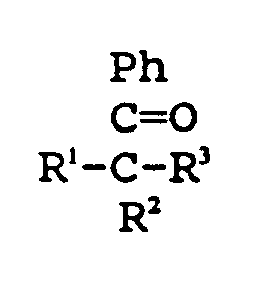
- Suitable activation groups include benzophenone, thioxanthone, and the like; acetophenone and its derivatives specified as: where
- the polymeric coating may then be linked with the substrate using known and appropriate techniques selected on the basis of the chosen activators, e.g., by ultraviolet light, heat, or ionizing radiation.
- Crosslinking with the listed polymers or oligomers may be accomplished by use of peroxides or azo compounds such as acetyl peroxide, cumyl peroxide, propionyl peroxide, benzoyl peroxide, or the like.
- a polyfunctional monomer such as divinylbenzene, ethylene glycol dimethacrylate, trimethylolpropane, pentaerythritol di- (or tri- or tetra-) methacrylate, diethylene glycol, or polyethylene glycol dimethacrylate, and similar multifunctional monomers capable of linking the polymers and oligomers discussed above is also appropriate for this invention.
- the polymeric coating may be applied to the catheter body or other polymeric substrate by any of a variety of methods, e.g., by spraying a solution or suspension of the polymers or of oligomers of the monomers onto the catheter or by dipping the catheter into the solution or suspension (after sealing the open ends, if so desired). Initiators may be included in the solution or applied in a separate step.
- the catheter may be sequentially or simultaneously dried to remove solvent after application of the polymer or oligomer to the polymeric body and crosslinked.
- the solution or suspension should be very dilute since only a very thin layer of polymer is to be applied.
- Preferred solvents for this procedure when using the preferred polymers and procedure are water, low molecular weight alcohols, and ethers, especially methanol, propanol, isopropanol, ethanol, and their mixtures.
- water miscible solvents e.g., tetrahydrofuran, methylene dichloride, methylethylketone, dimethylacetate, ethyl acetate, etc.
- tetrahydrofuran methylene dichloride
- methylethylketone dimethylacetate
- ethyl acetate etc.
- catheter bodies particularly preferred as a coating for the catheter bodies discussed below are physical mixtures of homo-oligomers of polyvinylpyrrolidone and polyacrylamide.
- the catheter bodies,or substrates are preferably sprayed or dipped, dried, and irradiated to produce a polymerized and crosslinked polymeric skin of the noted oligomers.
- the lubricious hydrophilic coating is preferably produced using generally simultaneous solvent removal and crosslinking operations.
- the coating is applied at a rate allowing "sheeting" of the solution, e.g., formation of a visibly smooth layer without "runs".
- the optimum coating rates are found at a linear removal rate between 0.25 and 2.0 inches/sec, preferably 0.5 and 1.0 inches/sec.
- the solvent evaporation operations may be conducted using a heating chamber suitable for maintaining the surface at a temperature between 25°C and the glass transition temperature (T g ) of the underlying substrate.
- Preferred temperatures are 50°C to 125°C.
- Most preferred for the noted and preferred solvent systems is the range of 75° to 110°C.
- Ultraviolet light sources may be used to crosslink the polymer precursors onto the substrate. Movement through an irradiation chamber having an ultraviolet light source at 90-375nm (preferably 300-350nm) having an irradiation density of 50-300 mW/cm 2 (preferably 150-250 mW/cm 2 )for a period of three to seven seconds is desired. Passage of a catheter through the chamber at a rate of 0.64 to 5.08 cm (0.25 to 2.0 inches)/second (1.27 cm to 2.54 cm or 0.5 to 1.0 inches/second) in a chamber having three to nine inches length is suitable. When using ionizing radiation, a radiation density of 1 to 100 kRads/cm 2 (preferably 20 to 50 kRads/cm 2 ) may be applied to the solution or suspension on the polymeric substrate.
- Exceptional durability of the resulting coating is produced by repetition of the dipping/solvent removal/irradiation steps up to five times. Preferred are two to four repetitions.
- FIG. 1 shows an infusion catheter (100) constructed according to one embodiment of the invention.
- the catheter (100) has an elongate tubular body (102) with proximal (104) and distal (106) ends and an open inner lumen (108) extending between the ends.
- the elongate tubular body (102) has three segments; a relatively flexible and strong distal segment (120), a relatively stiff tapered proximal segment (122) and a transition section or segment (124) between the proximal band distal segments that is less flexible than the distal segment (120) but more flexible than the proximal segment (122).
- the elongate tubular body (102) has a strong distal segment (120) which is desirably relatively flexible such that the catheter can easily navigate a tortuous vessel pathway.
- a force of about 4.5 x 10 -4 N (1 x 10 -4 pounds) corresponds to a deflection of the material that is 10° from horizontal, or only about 22.5 x 10 -4 N (5 x 10 -4 pounds) of force to deflect the material about 80° from horizontal.
- relatively strong is meant that the material has a burst pressure of greater than 13.5 bar (195 psi), more preferably, the burst pressure is between about 13.5 and 15.2 bar (195 and 220 psi).
- the flexible distal segment (120) has an open end which allows for the infusion of diagnostic, therapeutic, or vaso-occlusive agents into the target site.
- the flexible distal segment (120) preferably is made of a polymer that is springy and biologically compatible such as low density polyethylene, polyurethane, a block copolymer of polyamide, polyvinyl chloride, or silicone or blends of the above.
- the flexible distal segment (120) may carry one or more radiopaque bands (130) or may be doped with a radiopaque material such as barium sulfate, bismuth trioxide, bismuth carbonate, tungsten, tantalum or the like so that the location of the distal region of the catheter within the vessel may be visualized radiographically.
- the distal segment (120) typically makes up between about 5 and 25% of the total length of the tubular member and is between about 5 and 40 cm long, preferably between about 10 and 20 cm long.
- the inner diameter of the distal segment (120) may be between about 0.25 and 0.50 mm, more preferably between about 0.25 and 0.35 mm.
- the outer diameter of the distal segment may be between about 0.50 and 0.80 mm, more preferably between about 0.60 and 0.70 mm.
- the wall thickness of the distal segment 120 is between about 0.1 and 0.3 mm.
- the proximal segment (122) of the elongate tubular body (102), when used as a flow-directed infusion catheter, is relatively stiff such that it can be easily pushed thus eliminating the need for guidewire support.
- the proximal segment (122) may be made of a polymeric or metallic material that is relatively stiff and biologically compatible such as high density polyethylene, polypropylene, Nylon, polyurethane, polyimides, polyvinyl chloride, polysulfones, polyfluorocarbons, polyethylene terephthalate, their mixtures, copolymers; or polyester elastomers or a braided shaft (a polymer outer core with a metallic mesh inner core).
- the proximal segment (122) may comprise a tapered proximal section (134) for attachment to the proximal end fitting (150) and a distal section (132).
- the proximal section (134) of proximal segment (122) may make up between about 60% and 80% of the total length of the tubular member (102) and typically is between about 90 and 130 cm long, preferably between about 100 and 120 cm long.
- the largest inner diameter of the proximal section (134), measured at the proximal end (104) of the tubular member 102, is often between about 0.40 and 0.60 mm, more preferably between about 0.45 and 0.55 mm.
- the outer diameter of the proximal section (134) at the proximal end (104) of the tubular member (102) is between about 0.8 and 1.2 mm.
- the wall thickness of the proximal section (134) of proximal segment (122) is between about 0.1 and 0.4 mm, more preferably between about 0.2 and 0.3 mm.
- the distal section (132) of proximal segment (122) makes up between 10 and 20% of the total length of the tubular body (102) and is between about 20 and 40 cm long, preferably between about 20 and 30 cm long.
- the inner diameter of the distal section (132) of proximal segment (122) may be between about 0.20 and 0.50 mm, more preferably between about 0.25 and 0.35 mm.
- the outer diameter of the distal section (132) of proximal segment (122) is between about 0.60 and 0.90 mm, more preferably between about 0.60 and 0.70 mm.
- the wall thickness of the distal section (134) of proximal segment (122) is typically between about 0.1 and 0.3 mm.
- the transition section (124) of the elongate tubular body (102) is less stiff than the proximal segment (122) but more stiff than the distal segment (120).
- a suitable material that is biologically compatible is a polymer such as polyurethane, a block copolymer of polyamide, polyvinyl chloride or silicone with greater durometer reading (i.e. that is stiffer) than the flexible distal segment (120).
- the transition section (124) may be radiopaque and thus observable in the event that the catheter becomes lodged in a particular portion of the vasculature or buckles.
- the polymeric material may be doped with a radiopaque material such as barium sulfate, bismuth carbonate, bismuth trioxide, tungsten, tantalum or the like.
- the transition section (124) may make up between about 10 and 20% of the total length of the tubular member (102) and is between about 20 and 40 cm long, preferably between about 25 and 35 cm long.
- the transition section (124) may be of constant diameter or may be tapered.
- the inner diameter of the transition section (124) may be between about 0.20 and 0.50 mm, more preferably between about 0.20 and 0.35 mm.
- the outer diameter of the transition section (124) may be between about 0.50 and 0.90 mm, more preferably between about 0.60 and 0.70 mm.
- the wall thickness of the transition section (124) may be between about 0.1 and 0.3 mm.
- the proximal segment (122), transition section (124), and distal segment (120) are joined at junctions (140) and (142), respectively.
- the junctions may be formed by flaring, overlapping, and heat fusing the materials of the proximal segment (122) and transition section (124) and the transition section (124) and distal segment (120). Other methods for forming the junction, e.g., heat welding, solvent welding, etc. are also suitable.
- the distal segment (120), transition section (124) and distal section (132) of proximal segment (122) may all have approximately the same outside diameter or the transition section (124) and the distal section (132) of the proximal segment (122) may be tapered.
- a standard proximal end fitting (150) is attached to the proximal end (134) of the proximal segment (122) often by heat fusion with reinforcing tubing.
- FIG. 2 shows an embodiment of the distal segment (120) of the catheter where the tip (160) of the catheter is pre-shaped by heating with steam so that the distal end (106) points towards the wall of the vessel rather than in the direction of blood flow to increase the ease of manipulation through the tortuous vessel pathway.
- the particular embodiment shown is an "S" shape, but the tip may be any shape that allows for access to the particular vasculature being treated.
- One additional shape is that of a hockey stick. In this way, if the catheter becomes lodged against the vessel wall, the infusion of liquid through the catheter propels the distal end (106) of the catheter away from the vessel wall. Since the stiff proximal segment (122) is pushed, the distal segment (120) will be carried by the blood flood to the target site.
- the catheter described above is useful in delivering diagnostic, therapeutic, or vaso-occlusive agents and devices to deep tissue, usually without need for a guidewire.
- FIG. 3 shows a catheter assembly (200) for placing the infusion catheter (100) at the target site.
- An appropriate guiding catheter (202) is inserted into the vasculature using standard placement techniques.
- a rotating hemostatic valve (204) may be utilized by connection to the guiding catheter luer adapter (206).
- the guiding catheter (202) is continuously flushed with saline.
- the thumb-screw of the valve (204) is opened and the infusion catheter (100) is inserted through the rotating hemostatic valve (204).
- a Teflon-coated stainless steel stylet (208) is first inserted into the flow-directed infusion catheter (100) in order to prevent kinking of the infusion catheter (100) within the valve (204).
- the distal end (106) of the infusion catheter (100) is advanced proximal to the tip of the guiding catheter (202).
- the stylet (208) is then removed from the infusion catheter (100). Once the stylet (208) is removed, the infusion catheter (100) is pushed out of the guiding catheter (202).
- the flow-directed infusion catheter (100) is gently guided by the flow of blood in the vasculature to the target site.
- gentle pushing and pulling and injection of saline or contrast medium through the catheter lumen (108) may aid in the placement of the catheter at the target site.
- Such agents may include radiopaque agents for viewing blood vessel anatomy and blood flow characteristics in the target region, vaso-occlusive agents which can be used to produce small-artery vaso-occlusion in the tissue region supplied by the target vessel, and pharmacological agents, such as anti-tumor drugs or sclerosing agents such as alcohols, which are effective against identified disease states at the target site.
- Vaso-occlusive agents useful in the treatment of arteriovenous malformations include polymers that are activated in the presence of polar solvents such as water and include materials such as n-butylcyanoacrylate.
- vaso-occlusive agents useful in the treatment of arteriovenous malformations include polymer solutions that coagulate by diffusion of the solvent when in contact with blood. Polyvinyl acetate dissolved in dimethylsulfoxide is one such agent.
- vaso-occlusive coils may be injected into the infusion catheter and delivered to a target site to occlude the blood flow at that site.
- Figure 4 shows a variation of the invention in which the catheter is guided to its intended site by the use of a guidewire rather than through the use of blood flow.
- the catheter assembly (400) includes an elongate member (402) having a proximal end (404) and a distal end (406) and an inner lumen which extends between those two ends.
- the elongate tubular body (402) has three segments; a relatively flexible distal segment (408), a relatively stiff proximal segment (410) and a transition section or middle segment (412) (separated at junction (414) from the proximal segment) between the proximal and distal segments that is less flexible than the distal segment (408) but more flexible than the proximal segment (410).
- guidewire (414) often having a bent tip (416) to allow ease of passage through the vasculature.
- a catheter will have a small radiopaque band (418) of gold, platinum, palladium, or the like to permit monitoring of the catheter tip's position in relation to the tip of the guidewire or, when the guidewire is not in the catheter, to the vasculature itself.
- a standard proximal end fitting (420) may attached to the proximal end (404) of the proximal segment (410) often by heat fusion with reinforcing tubing. As is described in U.S. Pat. No.
- the variation of flexibility may be introduced into the catheter assembly by use of sections of discrete coaxial tubing, e.g., by use of an inner stiff tube of polypropylene or high density polyethylene covered by a flexible tube of low density polyethylene or silicone in the proximal section (410) with the inner tubing junction found at (410).
- a thinner wall inner tubing of the same polymer as found in the proximal section (410) may be used as the inner tubing in middle section (412) to provide decreased stiffness in the middle section (412).
- the outer coaxial layer could be of the same composition and dimensions from proximal end (404) to distal end (406).
- the catheters had three discrete sections: A proximal section of low-density polyethylene laminated over polypropylene tubing (having 0,559mm (0.022") I.D. and 0,991 mm (0.039") O.D.) of 115 cm. length, a transition section of low density polyethylene laminated over polypropylene tubing (having 0,559 mm (0.022”) I.D. and 0,991 mm (0.036”) O.D.) of 15 cm., and a distal section of low density polyethylene of 20 cm.
- the low density polyethylene outer covering was a single piece covering throughout the length of the catheters.
- the inventive catheter coating was produced using the following procedure:
- the comparative silicone catheter coating was applied using the following procedure:
- the catheters were separately introduced into a USCI Angiographic Systems Berenstein J-tip guiding catheter in a test rig allowing measurement of the force needed to push and to pull the catheters through the guiding catheter.
- Each of the catheters was tested through 20 pulls and pushes of 2 inches pushed and pulled at a rate of 2.54 cm (1 inch)/minute. In this way both absolute force needed to introduce the catheter may be recorded as well as the magnitude of all deterioration in the slipperiness.
- the measurements were taken for both the midsection and for the distal sections of the two catheters. MIDSECTION Pull. No.
- Comparative Invention 1 0.198 (0.044) 0.112 (0.025) 20 0.243 (0.054) 0.112 (0.025) DISTAL SECTION Pull. No. Comparative Invention 1 0.104 (0.023) 0.058 (0.013) 20 0.122 (0.027) 0.058 (0.013)
Landscapes
- Health & Medical Sciences (AREA)
- Life Sciences & Earth Sciences (AREA)
- Animal Behavior & Ethology (AREA)
- Veterinary Medicine (AREA)
- Public Health (AREA)
- General Health & Medical Sciences (AREA)
- Epidemiology (AREA)
- Engineering & Computer Science (AREA)
- Hematology (AREA)
- Heart & Thoracic Surgery (AREA)
- Biomedical Technology (AREA)
- Anesthesiology (AREA)
- Pulmonology (AREA)
- Biophysics (AREA)
- Materials For Medical Uses (AREA)
- Media Introduction/Drainage Providing Device (AREA)
- Medicines That Contain Protein Lipid Enzymes And Other Medicines (AREA)
Abstract
Description
characterised in that at least the distal segment has a lubricious coating comprising two or more polymers formed from, or a copolymer of, at least two monomers from N-vinylpyrrolidone, acrylamide or polyethylene glycol acrylate monomers and/or a polymer or copolymer comprising acrylamidomethylpropane sulfonic acid and its salts.
| MIDSECTION | ||
| Pull. No. | Force, N(lbs.) | |
| Comparative | Invention | |
| 1 | 0.198 (0.044) | 0.112 (0.025) |
| 20 | 0.243 (0.054) | 0.112 (0.025) |
| DISTAL SECTION | ||
| Pull. No. | Comparative | Invention |
| 1 | 0.104 (0.023) | 0.058 (0.013) |
| 20 | 0.122 (0.027) | 0.058 (0.013) |
Claims (15)
- A catheter assembly comprising an elongated tubular (102, 402) member having proximal and distal (104, 106, 404, 406) ends and an inner lumen (108) extending between these ends, the member comprising:(a) a relatively stiff proximal segment (122, 410);(b) a relatively flexible distal segment (120, 408); and(c) a transition section (124, 412) between the proximal and distal segments that is less flexible than the distal segment but more flexible than the proximal segment;
characterized in that at least the distal segment has a lubricious coating comprising two or more polymers formed from, or a copolymer of, at least two monomers from N-vinylpyrrolidone, acrylamide or polyethylene glycol acrylate monomers and/or a polymer or copolymer comprising acrylamidomethylpropane sulfonic acid and its salts. - A catheter according to claim 1 wherein the distal segment (120, 408) and the transition section (124, 412) are both coated with a lubricious coating.
- A catheter according to claim 1 or 2 wherein at least a portion of the proximal segment (122, 412) is also coated with a lubricious coating.
- A catheter according to claim 3 in which the polyethylene glycol acrylate is a mono-alkoxy polyethylene glycol mono(meth)acrylate.
- A catheter according to claim 4 wherein the mono(meth)acrylate comprises mono-methoxy triethylene glycol mono(meth)acrylate, mono-methoxy tetraethylene glycol mono(meth)acrylate or polyethylene glycol mono(meth)acrylate.
- A catheter according to any of claims 1 to 3 wherein the lubricious coating is of a copolymer of polyvinylpyrrolidone and polyacrylamide.
- A catheter according to any preceding claim wherein the distal segment (120, 408) has a burst pressure of at least about 13.5 bar (195 psi) and is made of a material which will show a force of about 4.5 x 10⁻⁴N (10-4 pounds) or less when ten centimetres of the material is deflected 10° from horizontal.
- A catheter according to claim 7 wherein the burst pressure of the distal segment (120, 408) is between about 13.5 to 15.2 bar (195 to 220 psi).
- A catheter according to claim 7 wherein the distal segment (120,408) is made of a material that further will show an additional force of about 4.5 x 10⁻⁵N (10-5 pounds) or less for each 1° of deflection of the material from horizontal.
- A catheter according to any preceding claim wherein the proximal segment (122, 410) is made of a polymeric material which is polyethylene, polypropylene, nylon, polyvinyl chloride, polyethylene terephthalate or other polyester elastomer and/or a polymer outer core with a metallic mesh inner core and laminates thereof.
- A catheter according to any preceding claim wherein the distal segment (120, 408) is made of a polymeric material which is polyethylene, polypropylene, polyurethane, a block copolymer of polyamide, polyvinyl chloride, silicone and/or a blend thereof.
- A catheter according to claim 11 wherein the polymeric material of the distal segment (120, 408) is doped with a metallic material which is barium sulfate, bismuth trioxide, bismuth carbonate, tungsten and/or tantalum.
- A catheter according to any preceding claim wherein the transition section (124, 412) is made of a polymeric material which is polyethylene, polypropylene, polyurethane, a block copolymer of polyamide, polyvinyl chloride and/or silicone or a laminate thereof.
- A catheter according to claim 13 wherein the polymeric material of the transition section (124, 412) is doped with a metallic material which is barium sulfate, bismuth trioxide, bismuth carbonate, tungsten and/or tantalum.
- A catheter according to any preceding claim wherein the distal segment (120, 408) is in an S-shaped or hockey stick-shaped configuration.
Applications Claiming Priority (3)
| Application Number | Priority Date | Filing Date | Title |
|---|---|---|---|
| US60401 | 1993-05-12 | ||
| US08/060,401 US5531715A (en) | 1993-05-12 | 1993-05-12 | Lubricious catheters |
| PCT/US1994/005343 WO1994026336A1 (en) | 1993-05-12 | 1994-05-12 | Lubricious catheters |
Publications (3)
| Publication Number | Publication Date |
|---|---|
| EP0693948A4 EP0693948A4 (en) | 1995-12-07 |
| EP0693948A1 EP0693948A1 (en) | 1996-01-31 |
| EP0693948B1 true EP0693948B1 (en) | 1998-07-22 |
Family
ID=22029228
Family Applications (1)
| Application Number | Title | Priority Date | Filing Date |
|---|---|---|---|
| EP94916763A Expired - Lifetime EP0693948B1 (en) | 1993-05-12 | 1994-05-12 | Lubricious catheters |
Country Status (10)
| Country | Link |
|---|---|
| US (4) | US5531715A (en) |
| EP (1) | EP0693948B1 (en) |
| JP (1) | JP2705852B2 (en) |
| AT (1) | ATE168568T1 (en) |
| AU (1) | AU680911B2 (en) |
| CA (1) | CA2127257C (en) |
| DE (1) | DE69411903T2 (en) |
| IL (1) | IL109637A0 (en) |
| TW (1) | TW275586B (en) |
| WO (1) | WO1994026336A1 (en) |
Cited By (2)
| Publication number | Priority date | Publication date | Assignee | Title |
|---|---|---|---|---|
| US7763077B2 (en) | 2003-12-24 | 2010-07-27 | Biomerix Corporation | Repair of spinal annular defects and annulo-nucleoplasty regeneration |
| US7803395B2 (en) | 2003-05-15 | 2010-09-28 | Biomerix Corporation | Reticulated elastomeric matrices, their manufacture and use in implantable devices |
Families Citing this family (281)
| Publication number | Priority date | Publication date | Assignee | Title |
|---|---|---|---|---|
| US5538512A (en) * | 1993-02-25 | 1996-07-23 | Zenzon; Wendy J. | Lubricious flow directed catheter |
| US5531715A (en) | 1993-05-12 | 1996-07-02 | Target Therapeutics, Inc. | Lubricious catheters |
| US5991650A (en) * | 1993-10-15 | 1999-11-23 | Ep Technologies, Inc. | Surface coatings for catheters, direct contacting diagnostic and therapeutic devices |
| JP2000511946A (en) * | 1994-07-22 | 2000-09-12 | アドバンスト・カーディオバスキュラー・システムズ・インコーポレイテッド | Hydrophilic coating material for internal use |
| US5662622A (en) * | 1995-04-04 | 1997-09-02 | Cordis Corporation | Intravascular catheter |
| EP0782463B1 (en) * | 1995-04-28 | 2000-03-01 | Target Therapeutics, Inc. | High performance braided catheter |
| US6824553B1 (en) | 1995-04-28 | 2004-11-30 | Target Therapeutics, Inc. | High performance braided catheter |
| WO1996034635A2 (en) * | 1995-05-05 | 1996-11-07 | Advanced Cardiovascular Systems, Inc. | Intraluminal device with lubricious surface |
| US6045734A (en) * | 1995-05-24 | 2000-04-04 | Becton Dickinson And Company | Process of making a catheter |
| US6774278B1 (en) | 1995-06-07 | 2004-08-10 | Cook Incorporated | Coated implantable medical device |
| AUPN766296A0 (en) * | 1996-01-22 | 1996-02-15 | Endogad Research Pty Limited | Trocar and introducing kit |
| SE9600276D0 (en) | 1996-01-25 | 1996-01-25 | Astra Ab | A wetting device for wetting a hydrophilic catheter and a urine collection bag incorporating said device |
| DK172941B1 (en) * | 1996-09-18 | 1999-10-11 | Coloplast As | A urinary catheter assembly |
| US5976120A (en) * | 1997-05-05 | 1999-11-02 | Micro Therapeutics, Inc. | Single segment microcatheter |
| US6221467B1 (en) | 1997-06-03 | 2001-04-24 | Scimed Life Systems, Inc. | Coating gradient for lubricious coatings on balloon catheters |
| US5902631A (en) * | 1997-06-03 | 1999-05-11 | Wang; Lixiao | Lubricity gradient for medical devices |
| WO1998058989A1 (en) † | 1997-06-20 | 1998-12-30 | Coloplast A/S | A hydrophilic coating and a method for the preparation thereof |
| EP1023617A1 (en) * | 1997-09-23 | 2000-08-02 | Novartis AG | Method for hydrogel surface treatment and article formed therefrom |
| US5891114A (en) * | 1997-09-30 | 1999-04-06 | Target Therapeutics, Inc. | Soft-tip high performance braided catheter |
| US6217566B1 (en) | 1997-10-02 | 2001-04-17 | Target Therapeutics, Inc. | Peripheral vascular delivery catheter |
| US6048338A (en) | 1997-10-15 | 2000-04-11 | Scimed Life Systems, Inc. | Catheter with spiral cut transition member |
| US5891110A (en) | 1997-10-15 | 1999-04-06 | Scimed Life Systems, Inc. | Over-the-wire catheter with improved trackability |
| US6159165A (en) | 1997-12-05 | 2000-12-12 | Micrus Corporation | Three dimensional spherical micro-coils manufactured from radiopaque nickel-titanium microstrand |
| US6221425B1 (en) | 1998-01-30 | 2001-04-24 | Advanced Cardiovascular Systems, Inc. | Lubricious hydrophilic coating for an intracorporeal medical device |
| US6295990B1 (en) | 1998-02-03 | 2001-10-02 | Salient Interventional Systems, Inc. | Methods and systems for treating ischemia |
| US6044845A (en) * | 1998-02-03 | 2000-04-04 | Salient Interventional Systems, Inc. | Methods and systems for treating ischemia |
| US6622367B1 (en) | 1998-02-03 | 2003-09-23 | Salient Interventional Systems, Inc. | Intravascular device and method of manufacture and use |
| US6097976A (en) * | 1998-02-27 | 2000-08-01 | Ep Technologies, Inc. | Catheter distal end assemblies with bonded surface coatings |
| US6517515B1 (en) | 1998-03-04 | 2003-02-11 | Scimed Life Systems, Inc. | Catheter having variable size guide wire lumen |
| US6113579A (en) | 1998-03-04 | 2000-09-05 | Scimed Life Systems, Inc. | Catheter tip designs and methods for improved stent crossing |
| US6796976B1 (en) * | 1998-03-06 | 2004-09-28 | Scimed Life Systems, Inc. | Establishing access to the body |
| US6171296B1 (en) | 1998-04-28 | 2001-01-09 | Microtherapeutics, Inc. | Flow directed catheter |
| US20050196431A1 (en) * | 1998-04-30 | 2005-09-08 | Upvan Narang | Adhesive applicator tip with a polymerization initiator, polymerization rate modifier, and/or bioactive material |
| US6200477B1 (en) * | 1998-05-06 | 2001-03-13 | Alltech Associates, Inc. | Continuously regenerated and integrated suppressor and detector for suppressed ion chromatography and method |
| US6106889A (en) * | 1998-06-11 | 2000-08-22 | Biocoat Incorporated | Method of selective coating of articles |
| US6126650A (en) * | 1998-06-30 | 2000-10-03 | Cordis Corporation | Flow directed catheter having radiopaque strain relief segment |
| US6093173A (en) * | 1998-09-09 | 2000-07-25 | Embol-X, Inc. | Introducer/dilator with balloon protection and methods of use |
| JP3885382B2 (en) * | 1998-10-05 | 2007-02-21 | 株式会社カネカ | Dilatation catheter |
| US8016852B2 (en) * | 1998-11-10 | 2011-09-13 | Stryker Corporation | Bioactive components for incorporation with vaso-occlusive members |
| PT2065061E (en) * | 1998-11-20 | 2015-07-30 | Coloplast As | METHOD FOR STERILIZING A MEDICAL DEVICE WITH A HYDROFILIC COATING |
| US6264630B1 (en) | 1998-12-23 | 2001-07-24 | Scimed Life Systems, Inc. | Balloon catheter having an oscillating tip configuration |
| US6192568B1 (en) | 1999-03-11 | 2001-02-27 | Ethicon, Inc. | Method of making an intravenous catheter assembly |
| US6673053B2 (en) | 1999-05-07 | 2004-01-06 | Scimed Life Systems, Inc. | Hydrophilic lubricity coating for medical devices comprising an antiblock agent |
| US6176849B1 (en) | 1999-05-21 | 2001-01-23 | Scimed Life Systems, Inc. | Hydrophilic lubricity coating for medical devices comprising a hydrophobic top coat |
| US6610035B2 (en) | 1999-05-21 | 2003-08-26 | Scimed Life Systems, Inc. | Hydrophilic lubricity coating for medical devices comprising a hybrid top coat |
| US6689120B1 (en) | 1999-08-06 | 2004-02-10 | Boston Scientific Scimed, Inc. | Reduced profile delivery system |
| CN1370086A (en) | 1999-08-24 | 2002-09-18 | 神经细胞治疗学公司 | Lumbar drainage catheter |
| US6592550B1 (en) * | 1999-09-17 | 2003-07-15 | Cook Incorporated | Medical device including improved expandable balloon |
| US6458867B1 (en) | 1999-09-28 | 2002-10-01 | Scimed Life Systems, Inc. | Hydrophilic lubricant coatings for medical devices |
| US6254921B1 (en) | 1999-12-08 | 2001-07-03 | Surmodics, Inc. | Coating process and apparatus |
| US6613432B2 (en) | 1999-12-22 | 2003-09-02 | Biosurface Engineering Technologies, Inc. | Plasma-deposited coatings, devices and methods |
| US6575888B2 (en) | 2000-01-25 | 2003-06-10 | Biosurface Engineering Technologies, Inc. | Bioabsorbable brachytherapy device |
| DE10015478A1 (en) * | 2000-03-29 | 2001-10-18 | Daniel Panzer | Medical lubricant for introduction of articles into body cavities, comprising aqueous solution of cellulose ether, especially useful for inserting respiratory aids or gynecological instruments |
| US6881209B2 (en) * | 2000-05-25 | 2005-04-19 | Cook Incorporated | Medical device including unitary, continuous portion of varying durometer |
| CN1245225C (en) * | 2000-06-12 | 2006-03-15 | 日本Acp株式会社 | Medical lead wires that double as catheters |
| US6623504B2 (en) | 2000-12-08 | 2003-09-23 | Scimed Life Systems, Inc. | Balloon catheter with radiopaque distal tip |
| DE10115740A1 (en) | 2001-03-26 | 2002-10-02 | Ulrich Speck | Preparation for restenosis prophylaxis |
| US20020156430A1 (en) * | 2001-04-19 | 2002-10-24 | Haarala Brett T. | Catheter slit valves |
| US7201940B1 (en) | 2001-06-12 | 2007-04-10 | Advanced Cardiovascular Systems, Inc. | Method and apparatus for thermal spray processing of medical devices |
| US8101196B2 (en) * | 2001-06-26 | 2012-01-24 | Biointeractions, Ltd. | Polysaccharide biomaterials and methods of use thereof |
| US7736336B2 (en) * | 2001-09-13 | 2010-06-15 | Allegiance Corporation | Paracentesis device having multiple detachable components |
| EP2428176B1 (en) | 2001-09-24 | 2013-10-23 | Applied Medical Resources Corporation | Bladeless obturator |
| US7947058B2 (en) | 2001-09-24 | 2011-05-24 | Applied Medical Resources Corporation | Bladeless optical obturator |
| US7201763B2 (en) * | 2001-10-24 | 2007-04-10 | Boston Scientific Scimed, Inc. | Distal balloon waist material relief and method of manufacture |
| JP4279676B2 (en) * | 2001-12-03 | 2009-06-17 | イコス コーポレイション | Small vessel ultrasound catheter |
| AU2002359576A1 (en) | 2001-12-03 | 2003-06-17 | Ekos Corporation | Catheter with multiple ultrasound radiating members |
| US7018346B2 (en) | 2001-12-18 | 2006-03-28 | Scimed Life Systems, Inc. | Guide wire with adjustable flexibility |
| US7914486B2 (en) * | 2001-12-20 | 2011-03-29 | Boston Scientific Scimed, Inc. | Catheter having an improved balloon-to-catheter bond |
| US6923787B2 (en) * | 2001-12-20 | 2005-08-02 | Scimed Life Systems, Inc. | Catheter having an improved balloon-to-catheter bond |
| WO2003072165A2 (en) * | 2002-02-28 | 2003-09-04 | Ekos Corporation | Ultrasound assembly for use with a catheter |
| US7008979B2 (en) | 2002-04-30 | 2006-03-07 | Hydromer, Inc. | Coating composition for multiple hydrophilic applications |
| CA2485481A1 (en) | 2002-05-16 | 2003-11-27 | Applied Medical Resources Corporation | Cone tip obturator |
| AU2003273339B2 (en) * | 2002-09-17 | 2008-08-14 | Iscience Interventional Corporation | Apparatus and method for surgical bypass of aqueous humor |
| DE10244847A1 (en) | 2002-09-20 | 2004-04-01 | Ulrich Prof. Dr. Speck | Medical device for drug delivery |
| US6970734B2 (en) * | 2002-12-02 | 2005-11-29 | Boston Scientific Scimed, Inc. | Flexible marker bands |
| US6918869B2 (en) * | 2002-12-02 | 2005-07-19 | Scimed Life Systems | System for administering a combination of therapies to a body lumen |
| US7032251B2 (en) * | 2002-12-10 | 2006-04-25 | Kimberly-Clark Worldwide, Inc. | Crosslinking agent for coated elastomeric articles |
| US7758880B2 (en) | 2002-12-11 | 2010-07-20 | Advanced Cardiovascular Systems, Inc. | Biocompatible polyacrylate compositions for medical applications |
| US7776926B1 (en) * | 2002-12-11 | 2010-08-17 | Advanced Cardiovascular Systems, Inc. | Biocompatible coating for implantable medical devices |
| EP1583569A4 (en) | 2003-01-03 | 2009-05-06 | Ekos Corp | Ultrasonic catheter with axial energy field |
| US20040133130A1 (en) * | 2003-01-06 | 2004-07-08 | Ferry Steven J. | Magnetically navigable medical guidewire |
| US8092450B2 (en) * | 2003-01-21 | 2012-01-10 | Baylis Medical Company Inc. | Magnetically guidable energy delivery apparatus and method of using same |
| US7438712B2 (en) * | 2003-03-05 | 2008-10-21 | Scimed Life Systems, Inc. | Multi-braid exterior tube |
| US7332227B2 (en) * | 2003-03-14 | 2008-02-19 | Becton, Dickinson And Company | Non-volatile lubricant system for medical devices |
| US6921880B2 (en) * | 2003-04-04 | 2005-07-26 | Constance F. Berger | Apparatus for heating bottles and method of manufacturing same |
| US7241455B2 (en) * | 2003-04-08 | 2007-07-10 | Boston Scientific Scimed, Inc. | Implantable or insertable medical devices containing radiation-crosslinked polymer for controlled delivery of a therapeutic agent |
| DE602004022397D1 (en) * | 2003-04-14 | 2009-09-17 | Cook Inc | DEPOSIT CATHETER / SLING WITH LARGE DIAMETER |
| IES20030294A2 (en) * | 2003-04-17 | 2004-10-20 | Medtronic Vascular Connaught | Coating for biomedical devices |
| WO2004093656A2 (en) | 2003-04-22 | 2004-11-04 | Ekos Corporation | Ultrasound enhanced central venous catheter |
| EP1631343B1 (en) * | 2003-04-28 | 2007-11-14 | Cook Incorporated | Flexible introducer sheath with varying durometer |
| US7914805B2 (en) * | 2003-07-31 | 2011-03-29 | Boston Scientific Scimed, Inc. | Implantable or insertable medical devices containing radiation-treated polymer for improved delivery of therapeutic agent |
| US20070198078A1 (en) | 2003-09-03 | 2007-08-23 | Bolton Medical, Inc. | Delivery system and method for self-centering a Proximal end of a stent graft |
| US8500792B2 (en) | 2003-09-03 | 2013-08-06 | Bolton Medical, Inc. | Dual capture device for stent graft delivery system and method for capturing a stent graft |
| US9198786B2 (en) | 2003-09-03 | 2015-12-01 | Bolton Medical, Inc. | Lumen repair device with capture structure |
| US8292943B2 (en) | 2003-09-03 | 2012-10-23 | Bolton Medical, Inc. | Stent graft with longitudinal support member |
| US11259945B2 (en) | 2003-09-03 | 2022-03-01 | Bolton Medical, Inc. | Dual capture device for stent graft delivery system and method for capturing a stent graft |
| US20080264102A1 (en) | 2004-02-23 | 2008-10-30 | Bolton Medical, Inc. | Sheath Capture Device for Stent Graft Delivery System and Method for Operating Same |
| US7763063B2 (en) | 2003-09-03 | 2010-07-27 | Bolton Medical, Inc. | Self-aligning stent graft delivery system, kit, and method |
| US11596537B2 (en) | 2003-09-03 | 2023-03-07 | Bolton Medical, Inc. | Delivery system and method for self-centering a proximal end of a stent graft |
| US8414524B2 (en) * | 2003-10-01 | 2013-04-09 | Micrus Endovascular Corporation | Long nose manipulatable catheter |
| US7762977B2 (en) | 2003-10-08 | 2010-07-27 | Hemosphere, Inc. | Device and method for vascular access |
| US20050096688A1 (en) * | 2003-10-30 | 2005-05-05 | Robert Slazas | Gripper for catheter shaft |
| SG183072A1 (en) * | 2004-01-23 | 2012-08-30 | Iscience Surgical Corp | Composite ophthalmic microcannula |
| JP2007520281A (en) * | 2004-01-29 | 2007-07-26 | イコス コーポレイション | Small vessel ultrasound catheter |
| US20080058704A1 (en) * | 2004-04-29 | 2008-03-06 | Michael Hee | Apparatus and Method for Ocular Treatment |
| KR20070033974A (en) * | 2004-04-29 | 2007-03-27 | 아이싸이언스 인터벤셔날 코포레이션 | Apparatus and method for surgical reinforcement of waterproof discharge |
| USD534649S1 (en) | 2004-06-08 | 2007-01-02 | Astra Tech Ab | Catheter package with collection bag |
| US7604830B2 (en) * | 2004-06-24 | 2009-10-20 | Cook Incorporated | Method and apparatus for coating interior surfaces of medical devices |
| EP2446803A1 (en) | 2004-06-25 | 2012-05-02 | Carnegie-Mellon University | Steerable, follow the leader device |
| EP3744271B1 (en) | 2004-06-29 | 2022-02-23 | Applied Medical Resources Corporation | Insufflating optical surgical instrument |
| DK2156852T3 (en) * | 2004-07-07 | 2011-08-08 | Coloplast As | Catheter comprising Estane 58212 |
| MX2007006335A (en) | 2004-11-29 | 2007-07-13 | Dsm Ip Assets Bv | Method for reducing the amount of migrateables of polymer coatings. |
| US7828790B2 (en) | 2004-12-03 | 2010-11-09 | Boston Scientific Scimed, Inc. | Selectively flexible catheter and method of use |
| US7815599B2 (en) | 2004-12-10 | 2010-10-19 | Boston Scientific Scimed, Inc. | Catheter having an ultra soft tip and methods for making the same |
| US7744574B2 (en) | 2004-12-16 | 2010-06-29 | Boston Scientific Scimed, Inc. | Catheter tip to reduce wire lock |
| US8864730B2 (en) | 2005-04-12 | 2014-10-21 | Rochester Medical Corporation | Silicone rubber male external catheter with absorbent and adhesive |
| US20060241000A1 (en) * | 2005-04-22 | 2006-10-26 | Cardiac Pacemakers, Inc. | Lubricious compound and medical device made of the same |
| US20060240059A1 (en) * | 2005-04-22 | 2006-10-26 | Cardiac Pacemakers, Inc. | Lubricious eluting polymer blend and coating made from the same |
| US20060240060A1 (en) * | 2005-04-22 | 2006-10-26 | Cardiac Pacemakers, Inc. | Lubricious compound and medical device made of the same |
| US20060240253A1 (en) * | 2005-04-22 | 2006-10-26 | Cardiac Pacemakers, Inc. | Guidewire and tube with lubricious coating |
| CA2609198A1 (en) * | 2005-06-02 | 2006-12-07 | Surmodics, Inc. | Hydrophilic polymeric coatings for medical articles |
| EP1745807B1 (en) * | 2005-07-18 | 2012-08-22 | Dentsply IH AB | Urinary catheter |
| EP1948047B1 (en) * | 2005-10-14 | 2010-09-08 | Applied Medical Resources Corporation | Surgical devices, systems and methods thereof having gel materials, gel coatings, or gel lubricants |
| WO2007050685A2 (en) | 2005-10-27 | 2007-05-03 | C.R. Bard, Inc. | Enhanced pre-wetted intermittent catheter with lubricious coating |
| EP1957127B1 (en) * | 2005-12-09 | 2018-02-21 | DSM IP Assets B.V. | Hydrophilic coating composition for urinary catheter |
| HUE032364T2 (en) | 2006-02-01 | 2017-09-28 | Hollister Inc | Methods of applying a hydrophilic coating to a substrate, and substrates having a hydrophilic coating |
| JP2007202846A (en) * | 2006-02-02 | 2007-08-16 | Ist Corp | Sliding member and manufacturing method thereof |
| US20090131884A1 (en) * | 2006-02-02 | 2009-05-21 | I.S.T. Corporation | Medical device for insertion into the human body, and method of manufacture |
| US8308711B2 (en) * | 2006-03-06 | 2012-11-13 | Advanced Cardiovascular Systems, Inc. | Catheter shaft with a lubricious surface |
| FR2898505B1 (en) * | 2006-03-16 | 2008-05-02 | Vygon Sa | UMBILICALLY CATHETER INTRODUCER AND KIT |
| WO2007127989A2 (en) * | 2006-04-28 | 2007-11-08 | Medtronic, Inc. | Wettable eptfe medical devices |
| KR100796509B1 (en) * | 2006-07-24 | 2008-01-21 | 동부일렉트로닉스 주식회사 | Manufacturing method of semiconductor device |
| BRPI0714489B8 (en) | 2006-08-14 | 2021-06-22 | Cardiorobotics Inc | airship multi-articulated device |
| EP2061528A1 (en) * | 2006-09-13 | 2009-05-27 | DSMIP Assets B.V. | Antimicrobial hydrophilic coating comprising metallic silver particles |
| US8828546B2 (en) * | 2006-09-13 | 2014-09-09 | Dsm Ip Assets B.V. | Coated medical device |
| US12161390B2 (en) | 2006-09-29 | 2024-12-10 | Boston Scientific Medical Device Limited | Connector system for electrosurgical device |
| US11666377B2 (en) | 2006-09-29 | 2023-06-06 | Boston Scientific Medical Device Limited | Electrosurgical device |
| AU2007303069B2 (en) | 2006-10-06 | 2013-03-21 | Applied Medical Resources Corporation | Visual insufflation port |
| CA2667576C (en) | 2006-10-24 | 2013-10-22 | Cardiorobotics, Inc. | Steerable multi-linked device having a modular link assembly |
| US20080140022A1 (en) * | 2006-12-08 | 2008-06-12 | Warsaw Orthopedic, Inc. | Coated Cannula with Protective Tip for Insertion Into a Patient |
| US10182833B2 (en) | 2007-01-08 | 2019-01-22 | Ekos Corporation | Power parameters for ultrasonic catheter |
| US20080245173A1 (en) | 2007-02-27 | 2008-10-09 | Carnegie Mellon University | System for controlling the movement of a multi-linked device |
| EP2125061A2 (en) * | 2007-02-28 | 2009-12-02 | DSM IP Assets B.V. | Hydrophilic coating |
| US8809411B2 (en) * | 2007-02-28 | 2014-08-19 | Dsm Ip Assets B.V. | Hydrophilic coating |
| US20080312639A1 (en) * | 2007-06-13 | 2008-12-18 | Jan Weber | Hardened polymeric lumen surfaces |
| ES2471118T3 (en) | 2007-06-22 | 2014-06-25 | Ekos Corporation | Method and apparatus for the treatment of intracranial hemorrhages |
| WO2009035457A1 (en) * | 2007-09-13 | 2009-03-19 | Reilly Dillon | Dip coating apparatus with height adjustable coating tubes and method of coating |
| US20090131886A1 (en) | 2007-11-16 | 2009-05-21 | Liu Y King | Steerable vertebroplasty system |
| US20090131867A1 (en) | 2007-11-16 | 2009-05-21 | Liu Y King | Steerable vertebroplasty system with cavity creation element |
| US9510885B2 (en) | 2007-11-16 | 2016-12-06 | Osseon Llc | Steerable and curvable cavity creation system |
| JP5432924B2 (en) | 2008-01-25 | 2014-03-05 | アプライド メディカル リソーシーズ コーポレイション | Insufflation access system |
| US20110295181A1 (en) | 2008-03-05 | 2011-12-01 | Hemosphere, Inc. | Implantable and removable customizable body conduit |
| ES2608823T3 (en) * | 2008-03-12 | 2017-04-17 | Dsm Ip Assets B.V. | Hydrophilic coating |
| CA2721495C (en) * | 2008-04-14 | 2017-12-12 | Carnegie Mellon University | Articulated device with visualization system |
| US8945096B2 (en) * | 2008-06-05 | 2015-02-03 | Carnegie Mellon University | Extendable articulated probe device |
| ES2638293T3 (en) | 2008-06-30 | 2017-10-19 | Bolton Medical Inc. | Abdominal aortic aneurysm systems |
| AU2009289450B2 (en) | 2008-09-05 | 2015-05-07 | Carnegie Mellon University | Multi-linked endoscopic device with spherical distal assembly |
| EP3799811B1 (en) | 2008-09-29 | 2022-03-30 | Applied Medical Resources Corporation | First-entry trocar system |
| US8425473B2 (en) | 2009-01-23 | 2013-04-23 | Iscience Interventional Corporation | Subretinal access device |
| US20100191177A1 (en) * | 2009-01-23 | 2010-07-29 | Iscience Interventional Corporation | Device for aspirating fluids |
| CA2752035A1 (en) * | 2009-02-20 | 2010-08-26 | Boston Scientific Scimed, Inc. | Hydrophilic coating that reduces particle development on ester-linked poly(ester-block-amide) |
| US9101506B2 (en) | 2009-03-13 | 2015-08-11 | Bolton Medical, Inc. | System and method for deploying an endoluminal prosthesis at a surgical site |
| JP5342301B2 (en) * | 2009-03-30 | 2013-11-13 | 三菱重工業株式会社 | Solar concentrator |
| US20100298832A1 (en) | 2009-05-20 | 2010-11-25 | Osseon Therapeutics, Inc. | Steerable curvable vertebroplasty drill |
| EP2442860B1 (en) | 2009-06-15 | 2019-03-27 | Perflow Medical Ltd. | Apparatus for allowing blood flow through an occluded vessel |
| JP2013500125A (en) | 2009-07-29 | 2013-01-07 | シー・アール・バード・インコーポレーテッド | Improved drainage device and / or catheter with retractable sleeve and method of using the same |
| EP2282070B1 (en) * | 2009-08-06 | 2012-10-17 | ECP Entwicklungsgesellschaft mbH | Catheter device with a coupling device for a drive device |
| WO2011019359A1 (en) | 2009-08-13 | 2011-02-17 | C. R. Bard, Inc. | Catheter having internal hydrating fluid storage and/or catheter package using the same and method of making and/or using the same |
| US8287890B2 (en) * | 2009-12-15 | 2012-10-16 | C.R. Bard, Inc. | Hydrophilic coating |
| EP3299056B2 (en) | 2009-12-23 | 2023-10-04 | C. R. Bard, Inc. | Catheter assembly/package utilizing a hydrating/hydrogel sleeve |
| US20110200828A1 (en) * | 2010-02-16 | 2011-08-18 | Biocoat Incorporated | Hydrophilic coatings for medical devices |
| WO2011109393A1 (en) | 2010-03-04 | 2011-09-09 | C.R. Bard, Inc. | Catheter assembly/package utilizing a hydrating/hydrogel sleeve and a foil outer layer and method of making and using the same |
| WO2011137377A1 (en) | 2010-04-29 | 2011-11-03 | Dfine, Inc. | System for use in treatment of vertebral fractures |
| EP2582745B1 (en) | 2010-06-16 | 2019-01-09 | DSM IP Assets B.V. | Coating formulation for preparing a hydrophilic coating |
| TWI875491B (en) | 2010-07-30 | 2025-03-01 | 瑞士商愛爾康公司 | Hydrated contact lens |
| US8541498B2 (en) | 2010-09-08 | 2013-09-24 | Biointeractions Ltd. | Lubricious coatings for medical devices |
| JP5795376B2 (en) | 2010-10-04 | 2015-10-14 | コヴィディエン リミテッド パートナーシップ | Distal access suction guide catheter |
| US9707375B2 (en) | 2011-03-14 | 2017-07-18 | Rochester Medical Corporation, a subsidiary of C. R. Bard, Inc. | Catheter grip and method |
| KR20140018324A (en) | 2011-05-02 | 2014-02-12 | 어플라이드 메디컬 리소시스 코포레이션 | Low-profile surgical universal access port |
| US10130789B2 (en) | 2011-06-30 | 2018-11-20 | Covidien Lp | Distal access aspiration guide catheter |
| US10779855B2 (en) | 2011-08-05 | 2020-09-22 | Route 92 Medical, Inc. | Methods and systems for treatment of acute ischemic stroke |
| US20130046375A1 (en) | 2011-08-17 | 2013-02-21 | Meng Chen | Plasma modified medical devices and methods |
| WO2013036643A2 (en) | 2011-09-06 | 2013-03-14 | Hemosphere, Inc. | Vascular access system with connector |
| EP2572749B1 (en) | 2011-09-23 | 2022-04-27 | Covidien LP | Distal access balloon guide catheter |
| CA2851668C (en) | 2011-10-12 | 2016-08-16 | Novartis Ag | Method for making uv-absorbing ophthalmic lenses by coating |
| US9821145B2 (en) | 2012-03-23 | 2017-11-21 | Pressure Products Medical Supplies Inc. | Transseptal puncture apparatus and method for using the same |
| WO2013154749A1 (en) | 2012-04-12 | 2013-10-17 | Bolton Medical, Inc. | Vascular prosthetic delivery device and method of use |
| WO2013179103A1 (en) | 2012-05-31 | 2013-12-05 | Baylis Medical Inc. | Radiofrequency perforation apparatus |
| WO2014035639A1 (en) | 2012-08-29 | 2014-03-06 | Cardiac Pacemakers, Inc. | Enhanced low friction coating for medical leads and methods of making |
| US9872969B2 (en) | 2012-11-20 | 2018-01-23 | Rochester Medical Corporation, a subsidiary of C.R. Bard, Inc. | Catheter in bag without additional packaging |
| US10092728B2 (en) | 2012-11-20 | 2018-10-09 | Rochester Medical Corporation, a subsidiary of C.R. Bard, Inc. | Sheath for securing urinary catheter |
| EP2922594B1 (en) | 2012-11-21 | 2018-02-14 | Cardiac Pacemakers, Inc. | Medical electrodes with layered coatings |
| CN104871036B (en) | 2012-12-17 | 2019-12-10 | 诺华股份有限公司 | Method for making improved UV-absorbing ophthalmic lenses |
| EP2934632B8 (en) | 2012-12-20 | 2022-07-06 | Embecta Corp. | Device and method for inhibiting movement of a medical device in a patient |
| WO2014107670A1 (en) * | 2013-01-04 | 2014-07-10 | Surmodics, Inc. | Low particulate lubricious coating with vinyl pyrrolidone and acidic polymer-containing layers |
| JP6437469B2 (en) | 2013-03-12 | 2018-12-12 | ベイリス メディカル カンパニー インコーポレイテッドBaylis Medical Company Inc. | Medical device having support structure |
| US11937873B2 (en) | 2013-03-12 | 2024-03-26 | Boston Scientific Medical Device Limited | Electrosurgical device having a lumen |
| US8998882B2 (en) | 2013-03-13 | 2015-04-07 | C. R. Bard, Inc. | Enhanced pre-wetted intermittent catheter with lubricious coating |
| US9439751B2 (en) | 2013-03-15 | 2016-09-13 | Bolton Medical, Inc. | Hemostasis valve and delivery systems |
| CA3220441A1 (en) | 2013-03-15 | 2015-09-17 | Boston Scientific Medical Device Limited | Electrosurgical device having a distal aperture |
| US9255173B2 (en) | 2013-03-15 | 2016-02-09 | Lake Region Manufacturing, Inc. | Oxirane (ethylene oxide) polyurethane coatings |
| US9714361B2 (en) | 2013-03-15 | 2017-07-25 | Lake Region Manfacturing, Inc. | Oxirane (ethylene oxide) polyurethane coatings |
| US9844383B2 (en) | 2013-05-08 | 2017-12-19 | Embolx, Inc. | Devices and methods for low pressure tumor embolization |
| JP6401781B2 (en) | 2013-05-08 | 2018-10-10 | エンボルクス, インク.Embolx, Inc. | Apparatus and method for transvascular tumor embolization with integrated flow regulation |
| KR102262007B1 (en) | 2013-08-07 | 2021-06-08 | 베이리스 메디컬 컴퍼니 아이엔씨. | Methods and devices for puncturing tissue |
| MY180543A (en) | 2013-12-17 | 2020-12-01 | Novartis Ag | A silicone hydrogel lens with a crosslinked hydrophilic coating |
| WO2015092768A1 (en) | 2013-12-20 | 2015-06-25 | Baylis Medical Company Inc. | Steerable medical device handle |
| US10682453B2 (en) | 2013-12-20 | 2020-06-16 | Merit Medical Systems, Inc. | Vascular access system with reinforcement member |
| ES2895849T3 (en) | 2014-08-26 | 2022-02-22 | Bard Inc C R | Urinary catheter |
| CN106715101B (en) | 2014-08-26 | 2019-11-05 | 诺华股份有限公司 | Method for applying a stable coating on a silicone hydrogel contact lens |
| US10780246B2 (en) * | 2014-09-12 | 2020-09-22 | Callisyn Biomedical, Inc. | Vascular microcatheter |
| US11065019B1 (en) | 2015-02-04 | 2021-07-20 | Route 92 Medical, Inc. | Aspiration catheter systems and methods of use |
| EP3878484A1 (en) | 2015-04-16 | 2021-09-15 | Hollister Incorporated | Hydrophilic coatings and methods of forming the same |
| EP3307388B1 (en) | 2015-06-10 | 2022-06-22 | Ekos Corporation | Ultrasound catheter |
| US10569047B2 (en) | 2015-06-17 | 2020-02-25 | Hollister Incorporated | Water disintegrable flushable catheter |
| CN107690314B (en) | 2015-07-16 | 2020-06-09 | 珀弗娄医疗有限公司 | Apparatus and method for vascular obstruction removal |
| US11324548B2 (en) | 2015-08-21 | 2022-05-10 | Baylis Medical Company Inc. | Transvascular electrosurgical devices and systems and methods of using the same |
| CA2995553C (en) | 2015-09-09 | 2024-04-23 | Baylis Medical Company Inc. | Epicardial access system & methods |
| US10716915B2 (en) | 2015-11-23 | 2020-07-21 | Mivi Neuroscience, Inc. | Catheter systems for applying effective suction in remote vessels and thrombectomy procedures facilitated by catheter systems |
| CN108369291B (en) | 2015-12-15 | 2021-07-20 | 爱尔康公司 | Method for applying a stable coating to a silicone hydrogel contact lens |
| JP2019503777A (en) | 2016-01-07 | 2019-02-14 | ベイリス メディカル カンパニー インコーポレイテッドBaylis Medical Company Inc. | Hybrid transseptal dilator and method of using the same |
| US12268824B2 (en) | 2018-07-27 | 2025-04-08 | Embolx, Inc. | Shaped catheter tip for tracking over a guidewire through turns in the vasculature |
| US11464948B2 (en) | 2016-02-16 | 2022-10-11 | Embolx, Inc. | Balloon catheters and methods of manufacture and use |
| US10350382B1 (en) | 2018-06-08 | 2019-07-16 | Embolx, Inc. | High torque catheter and methods of manufacture |
| US9550046B1 (en) | 2016-02-16 | 2017-01-24 | Embolx, Inc. | Balloon catheter and methods of fabrication and use |
| EP3436096B1 (en) | 2016-03-31 | 2025-04-16 | Surmodics, Inc. | Lubricious coating for medical device |
| CN109862834B (en) | 2016-10-27 | 2022-05-24 | Dfine有限公司 | Bendable osteotome with cement delivery channel |
| JP2019536532A (en) | 2016-11-01 | 2019-12-19 | ベイリス メディカル カンパニー インコーポレイテッドBaylis Medical Company Inc. | Method and device for piercing tissue |
| WO2018089625A2 (en) | 2016-11-10 | 2018-05-17 | Merit Medical Systems, Inc. | Anchor device for vascular anastomosis |
| JP7256119B2 (en) | 2016-11-28 | 2023-04-11 | ディファイン インコーポレイテッド | Tumor resection device and related method |
| CN110035704B (en) | 2016-12-09 | 2022-09-06 | Dfine有限公司 | Medical device for treating hard tissue and related methods |
| EP3554571B1 (en) | 2016-12-16 | 2024-11-13 | Surmodics, Inc. | Hydrophobic active agent particle coatings and methods for treatment |
| WO2018129180A1 (en) | 2017-01-06 | 2018-07-12 | Dfine, Inc. | Osteotome with a distal portion for simultaneous advancement and articulation |
| WO2018132573A1 (en) | 2017-01-12 | 2018-07-19 | Merit Medical Systems, Inc. | Methods and systems for selection and use of connectors between conduits |
| WO2018136703A1 (en) | 2017-01-20 | 2018-07-26 | Hollister Incorporated | Method for sterilizing a substrate having a hydrophilic coating and sterilized substrates |
| US11590010B2 (en) | 2017-01-25 | 2023-02-28 | Merit Medical Systems, Inc. | Methods and systems for facilitating laminar flow between conduits |
| US11220582B2 (en) | 2017-03-03 | 2022-01-11 | Harland Medical Systems, Inc. | Coating composition comprised of a hydrophilic crosslinker, a hydrophobic crosslinker and optionally a hydrogel and methods of making and using the same |
| ES2991874T3 (en) | 2017-03-06 | 2024-12-05 | Merit Medical Systems Inc | Systems and methods for removing clots from vascular access sets |
| EP3600150B1 (en) | 2017-03-24 | 2023-05-17 | Merit Medical Systems, Inc. | Subcutaneous vascular assemblies for improving blood flow |
| WO2019014444A2 (en) | 2017-07-14 | 2019-01-17 | Merit Medical Systems, Inc. | Releasable conduit connectors |
| EP3655086A4 (en) | 2017-07-20 | 2021-04-07 | Merit Medical Systems, Inc. | METHODS AND SYSTEMS FOR COUPLING PIPES |
| KR20200030610A (en) | 2017-08-10 | 2020-03-20 | 베이리스 메디컬 컴퍼니 아이엔씨. | Heat exchange and temperature sensing devices and methods of use |
| WO2019050962A1 (en) | 2017-09-05 | 2019-03-14 | Harland Medical Systems, Inc. | A coating apparatus with an automatic fluid level system, and methods of using the same |
| EP3675779B1 (en) | 2017-09-19 | 2025-09-10 | C. R. Bard, Inc. | Urinary catheter bridging device, systems and methods thereof |
| WO2019089569A1 (en) | 2017-10-31 | 2019-05-09 | Merit Medical Systems, Inc. | Subcutaneous vascular assemblies for improving blood flow and related devices and methods |
| EP3579909B1 (en) | 2017-12-05 | 2020-09-09 | Pedersen, Wesley Robert | Transseptal guide wire puncture system |
| HUE057348T2 (en) | 2017-12-13 | 2022-05-28 | Alcon Inc | Method for producing mps-compatible water gradient contact lenses |
| JPWO2019187860A1 (en) * | 2018-03-30 | 2021-04-08 | テルモ株式会社 | Medical devices and methods of manufacturing medical devices |
| AU2019265786B2 (en) | 2018-05-08 | 2024-10-10 | Boston Scientific Medical Device Limited | Coupling mechanisms for medical devices |
| US10899944B2 (en) | 2018-10-29 | 2021-01-26 | Lake Region Manufacturing, Inc. | Polyurethane urea-containing adipic acid dihydrazide where active hydrogens react with the epoxy group found on glycidol to form a diol |
| EP3876857B1 (en) | 2018-11-08 | 2025-08-27 | Dfine, Inc. | Ablation systems with parameter-based modulation and related devices |
| US20220047843A1 (en) * | 2018-12-21 | 2022-02-17 | Crannmed Limited | A Tube Having an Interior Lubricious Coating and Systems and Methods of Applying the Same |
| KR20220021468A (en) | 2019-04-29 | 2022-02-22 | 베이리스 메디컬 컴퍼니 아이엔씨. | Transseptal system, device and method |
| CN114555167A (en) | 2019-08-20 | 2022-05-27 | 埃姆博尔克斯公司 | Catheter and methods of making and using same |
| ES2987037T3 (en) * | 2019-09-11 | 2024-11-13 | Neuravi Ltd | Expandable buccal catheter |
| EP4031040B1 (en) | 2019-09-18 | 2025-04-09 | Merit Medical Systems, Inc. | Osteotome with inflatable portion and multiwire articulation |
| US11759190B2 (en) | 2019-10-18 | 2023-09-19 | Boston Scientific Medical Device Limited | Lock for medical devices, and related systems and methods |
| US11359156B2 (en) | 2019-10-21 | 2022-06-14 | Biocoat, Inc. | UV cure basecoatings for medical devices |
| US12037560B2 (en) | 2019-10-21 | 2024-07-16 | Biocoat, Incorporated | UV cure topcoatings for medical devices |
| US11801087B2 (en) | 2019-11-13 | 2023-10-31 | Boston Scientific Medical Device Limited | Apparatus and methods for puncturing tissue |
| US12214146B2 (en) | 2019-12-11 | 2025-02-04 | Biocoat, Incorporated | Controlled release of a hydrophilic agent from a coated surface |
| US11724070B2 (en) | 2019-12-19 | 2023-08-15 | Boston Scientific Medical Device Limited | Methods for determining a position of a first medical device with respect to a second medical device, and related systems and medical devices |
| US11931098B2 (en) | 2020-02-19 | 2024-03-19 | Boston Scientific Medical Device Limited | System and method for carrying out a medical procedure |
| US11986209B2 (en) | 2020-02-25 | 2024-05-21 | Boston Scientific Medical Device Limited | Methods and devices for creation of communication between aorta and left atrium |
| US12082792B2 (en) | 2020-02-25 | 2024-09-10 | Boston Scientific Medical Device Limited | Systems and methods for creating a puncture between aorta and the left atrium |
| US11819243B2 (en) | 2020-03-19 | 2023-11-21 | Boston Scientific Medical Device Limited | Medical sheath and related systems and methods |
| US12011279B2 (en) | 2020-04-07 | 2024-06-18 | Boston Scientific Medical Device Limited | Electro-anatomic mapping system |
| US11826075B2 (en) | 2020-04-07 | 2023-11-28 | Boston Scientific Medical Device Limited | Elongated medical assembly |
| US12420067B2 (en) | 2020-05-12 | 2025-09-23 | Boston Scientific Medical Device Limited | Guidewire assembly |
| US11938285B2 (en) | 2020-06-17 | 2024-03-26 | Boston Scientific Medical Device Limited | Stop-movement device for elongated medical assembly |
| EP4167890A4 (en) | 2020-06-17 | 2024-07-31 | Boston Scientific Medical Device Limited | Electroanatomical mapping system |
| US11937796B2 (en) | 2020-06-18 | 2024-03-26 | Boston Scientific Medical Device Limited | Tissue-spreader assembly |
| EP4171449A1 (en) | 2020-06-24 | 2023-05-03 | Bolton Medical, Inc. | Anti-backspin component for vascular prosthesis delivery device |
| US12343042B2 (en) | 2020-07-16 | 2025-07-01 | Boston Scientific Medical Device Limited | Pericardial puncture device and method |
| US12042178B2 (en) | 2020-07-21 | 2024-07-23 | Boston Scientific Medical Device Limited | System of medical devices and method for pericardial puncture |
| US12005202B2 (en) | 2020-08-07 | 2024-06-11 | Boston Scientific Medical Device Limited | Catheter having tissue-engaging device |
| US12396785B2 (en) | 2020-08-12 | 2025-08-26 | Boston Scientific Medical Device Limited | System of medical devices and method for pericardial puncture |
| CA3128527A1 (en) | 2020-09-10 | 2022-03-10 | Baylis Medical Company Inc. | Elongated medical catheter including marker band |
| US11980412B2 (en) | 2020-09-15 | 2024-05-14 | Boston Scientific Medical Device Limited | Elongated medical sheath |
| EP4363019A4 (en) | 2021-07-02 | 2025-07-16 | Embolx Inc | Catheters adapted for agent delivery |
| CN114712568B (en) * | 2022-06-07 | 2023-01-17 | 中国人民解放军总医院第一医学中心 | A kind of surface modified silicone rubber gastric tube and preparation method thereof |
Citations (1)
| Publication number | Priority date | Publication date | Assignee | Title |
|---|---|---|---|---|
| US5171232A (en) * | 1989-06-13 | 1992-12-15 | Cordis Corporation | Catheter having highly radiopaque, flexible tip |
Family Cites Families (74)
| Publication number | Priority date | Publication date | Assignee | Title |
|---|---|---|---|---|
| US2236397A (en) * | 1939-04-17 | 1941-03-25 | New Wrinkle Inc | Method of drying finishes |
| US3566874A (en) | 1968-08-13 | 1971-03-02 | Nat Patent Dev Corp | Catheter |
| US3955012A (en) * | 1970-08-06 | 1976-05-04 | Zaidan Hojin, Seisan Kaihatsu Kagaku Kenkyusho | Method for manufacturing medical articles composed of silicone rubber coated with collagen |
| US3695921A (en) | 1970-09-09 | 1972-10-03 | Nat Patent Dev Corp | Method of coating a catheter |
| US4055682A (en) * | 1971-11-19 | 1977-10-25 | High Voltage Engineering Corporation | Catheter and the method of making |
| US3957918A (en) * | 1974-12-31 | 1976-05-18 | Ford Motor Company | Radiation polymerizable coating composition containing an unsaturated phosphoric ester |
| US4407855A (en) * | 1980-01-07 | 1983-10-04 | Panelographic Corporation | Method for forming an abrasion resistant coating from cellulose ester and pentaerythritol acrylates |
| US4337327A (en) * | 1980-07-07 | 1982-06-29 | S.K.Y. Polymers, Inc. | Novel block copolymers including acrylonitrile sequences and sequences including units derived from glutarimide units and processes for preparing same |
| US4379874A (en) * | 1980-07-07 | 1983-04-12 | Stoy Vladimir A | Polymer composition comprising polyacrylonitrile polymer and multi-block copolymer |
| US4370451A (en) * | 1980-07-07 | 1983-01-25 | S.K.Y. Polymers | Novel block copolymers including acrylonitrile sequences and sequences including units derived from glutarimide units and processes for preparing same |
| US4420589A (en) * | 1980-07-07 | 1983-12-13 | Stoy Vladimir A | Polymer composition including polyacrylonitrile polymers and process for preparing same |
| US4331783A (en) * | 1980-09-17 | 1982-05-25 | S.K.Y. Polymers | Novel block copolymers including acrylonitrile sequences and glutarimide units and processes for preparing same |
| US4369294A (en) * | 1980-09-17 | 1983-01-18 | S.K.Y. Polmers | Novel block copolymers including acrylonitrile sequences and glutarimide units and processes for preparing same |
| US4326532A (en) * | 1980-10-06 | 1982-04-27 | Minnesota Mining And Manufacturing Company | Antithrombogenic articles |
| US4373009A (en) * | 1981-05-18 | 1983-02-08 | International Silicone Corporation | Method of forming a hydrophilic coating on a substrate |
| US4773901A (en) * | 1981-12-31 | 1988-09-27 | C. R. Bard, Inc. | Catheter with selectively rigidified portion |
| US4477327A (en) * | 1982-04-19 | 1984-10-16 | Ford Motor Company | Discoloration resistant, flexible, radiation curable coating compositions |
| US4503126A (en) * | 1982-08-18 | 1985-03-05 | Foster Grant Corporation | Method of making an abrasion resistant coating on a solid substrate and articles produced thereby |
| US5002582A (en) * | 1982-09-29 | 1991-03-26 | Bio-Metric Systems, Inc. | Preparation of polymeric surfaces via covalently attaching polymers |
| US4973493A (en) * | 1982-09-29 | 1990-11-27 | Bio-Metric Systems, Inc. | Method of improving the biocompatibility of solid surfaces |
| US4722906A (en) * | 1982-09-29 | 1988-02-02 | Bio-Metric Systems, Inc. | Binding reagents and methods |
| US4663163A (en) * | 1983-02-14 | 1987-05-05 | Hou Kenneth C | Modified polysaccharide supports |
| US4526579A (en) * | 1983-06-17 | 1985-07-02 | Pfizer Inc. | Method for graft copolymerization to natural rubber articles |
| US4773902A (en) * | 1983-10-24 | 1988-09-27 | Deseret Medical, Inc. | Oxidized cellulose as a medical lubricant |
| US4668224A (en) * | 1983-10-24 | 1987-05-26 | Warner-Lambert Company | Oxidized cellulose as a medical lubricant |
| NL8401362A (en) * | 1984-04-27 | 1985-11-18 | Tno | METHOD OF COOPERATING PARTICULAR MATERIALS WITH A POLYMER IN ORDER TO ENABLE THE REGULATED DELIVERY OF THESE MATERIALS TO THE ENVIRONMENT AND THEREFORE OBTAINED COVERED MATERIAL. |
| US4589873A (en) * | 1984-05-29 | 1986-05-20 | Becton, Dickinson And Company | Method of applying a hydrophilic coating to a polymeric substrate and articles prepared thereby |
| DE3582754D1 (en) * | 1984-06-04 | 1991-06-13 | Terumo Corp | MEDICAL TOOL AND PRODUCTION METHOD. |
| US4751133A (en) * | 1984-11-13 | 1988-06-14 | Thermedics, Inc. | Medical patches and processes for producing same |
| GB2172203B (en) * | 1985-03-14 | 1988-11-09 | Univ Manchester | A urethral catheter |
| US4634432A (en) * | 1985-05-13 | 1987-01-06 | Nuri Kocak | Introducer sheath assembly |
| SE8504501D0 (en) * | 1985-09-30 | 1985-09-30 | Astra Meditec Ab | METHOD OF FORMING AN IMPROVED HYDROPHILIC COATING ON A POLYMER SURFACE |
| US4806430A (en) * | 1985-12-03 | 1989-02-21 | Becton, Dickinson And Company | Film-forming silicone compositions having lubricating properties |
| US4720392A (en) * | 1985-12-04 | 1988-01-19 | Mark Livesay | Process for controlling monomeric emissions |
| US4838876A (en) * | 1986-04-29 | 1989-06-13 | The Kendall Company | Silicone rubber catheter having improved surface morphology |
| US4739768B2 (en) * | 1986-06-02 | 1995-10-24 | Target Therapeutics Inc | Catheter for guide-wire tracking |
| US4979959A (en) * | 1986-10-17 | 1990-12-25 | Bio-Metric Systems, Inc. | Biocompatible coating for solid surfaces |
| US4748651A (en) | 1987-06-12 | 1988-05-31 | Keptel, Inc. | Multiline transmission line test receptacle with provision for testing each line |
| US5001009A (en) * | 1987-09-02 | 1991-03-19 | Sterilization Technical Services, Inc. | Lubricious hydrophilic composite coated on substrates |
| US4943618A (en) * | 1987-12-18 | 1990-07-24 | Kingston Technologies Limited Partnership | Method for preparing polyacrylonitrile copolymers by heterogeneous reaction of polyacrylonitrile aquagel |
| US4975300A (en) * | 1987-12-31 | 1990-12-04 | Minnesota Mining And Manufacturing Company | Method for curing an organic coating using condensation heating and radiation energy |
| US4844986A (en) * | 1988-02-16 | 1989-07-04 | Becton, Dickinson And Company | Method for preparing lubricated surfaces and product |
| US4846812A (en) * | 1988-03-22 | 1989-07-11 | Menlo Care, Inc. | Softening catheter |
| US5061738A (en) * | 1988-04-18 | 1991-10-29 | Becton, Dickinson And Company | Blood compatible, lubricious article and composition and method therefor |
| US4884579A (en) * | 1988-04-18 | 1989-12-05 | Target Therapeutics | Catheter guide wire |
| US5182317A (en) | 1988-06-08 | 1993-01-26 | Cardiopulmonics, Inc. | Multifunctional thrombo-resistant coatings and methods of manufacture |
| WO1990001344A1 (en) * | 1988-08-09 | 1990-02-22 | Toray Industries, Inc. | Slippery medical material and process for its production |
| US5634946A (en) * | 1988-08-24 | 1997-06-03 | Focal, Inc. | Polymeric endoluminal paving process |
| US4968532A (en) * | 1989-01-13 | 1990-11-06 | Ciba-Geigy Corporation | Process for graft copolymerization on surfaces of preformed substrates to modify surface properties |
| US5004461A (en) * | 1989-03-23 | 1991-04-02 | Wilson Joseph E | Methods for rendering plastics thromboresistant and product |
| US5272012A (en) * | 1989-06-23 | 1993-12-21 | C. R. Bard, Inc. | Medical apparatus having protective, lubricious coating |
| US5135516A (en) * | 1989-12-15 | 1992-08-04 | Boston Scientific Corporation | Lubricious antithrombogenic catheters, guidewires and coatings |
| US5310581A (en) * | 1989-12-29 | 1994-05-10 | The Dow Chemical Company | Photocurable compositions |
| US5069673A (en) * | 1990-02-07 | 1991-12-03 | Cordis Corporation | Catheter with double step-down bore |
| US5084033A (en) * | 1990-03-12 | 1992-01-28 | Minnesota Mining And Manufacturing Company | Arterial cannula tip and method of manufacture |
| US5147315A (en) * | 1990-04-06 | 1992-09-15 | C. R. Bard, Inc. | Access catheter and system for use in the female reproductive system |
| DK146790D0 (en) * | 1990-06-15 | 1990-06-15 | Meadox Surgimed As | PROCEDURE FOR THE PREPARATION OF A FERTILIZER COATING COATING AND MEDICAL INSTRUMENT WITH COATING COATING |
| JP2830440B2 (en) * | 1990-09-21 | 1998-12-02 | 東洋紡績株式会社 | Cannula |
| WO1992007464A1 (en) * | 1990-10-24 | 1992-05-14 | University Of Florida | Combined plasma and gamma radiation polymerization method for modifying surfaces |
| CA2065092A1 (en) * | 1991-04-05 | 1992-10-06 | Masayoshi Kurisu | Curable coating resin composition and information recording medium using the same |
| US5234416A (en) * | 1991-06-06 | 1993-08-10 | Advanced Cardiovascular Systems, Inc. | Intravascular catheter with a nontraumatic distal tip |
| DE4122743C1 (en) * | 1991-07-10 | 1992-11-26 | Fraunhofer-Gesellschaft Zur Foerderung Der Angewandten Forschung Ev, 8000 Muenchen, De | |
| US5281682A (en) * | 1992-03-03 | 1994-01-25 | Air Products And Chemicals, Inc. | Radiation curable compositions and method of use |
| US5217802A (en) * | 1992-03-17 | 1993-06-08 | Millipore Corporation | Hydrophobic polymeric membrane composites |
| US5441759A (en) * | 1992-09-03 | 1995-08-15 | Sherwood Medical Company | Method to stabilize TDMAC heparin coating |
| US5342621A (en) | 1992-09-15 | 1994-08-30 | Advanced Cardiovascular Systems, Inc. | Antithrombogenic surface |
| US5336205A (en) * | 1993-02-25 | 1994-08-09 | Target Therapeutics, Inc. | Flow directed catheter |
| US5538512A (en) * | 1993-02-25 | 1996-07-23 | Zenzon; Wendy J. | Lubricious flow directed catheter |
| US5401257A (en) * | 1993-04-27 | 1995-03-28 | Boston Scientific Corporation | Ureteral stents, drainage tubes and the like |
| US5300048A (en) * | 1993-05-12 | 1994-04-05 | Sabin Corporation | Flexible, highly radiopaque plastic material catheter |
| US5531715A (en) | 1993-05-12 | 1996-07-02 | Target Therapeutics, Inc. | Lubricious catheters |
| US5603991A (en) * | 1995-09-29 | 1997-02-18 | Target Therapeutics, Inc. | Method for coating catheter lumens |
| US5830539A (en) * | 1995-11-17 | 1998-11-03 | The State Of Oregon Acting By And Through The State Board Of Higher Education On Behalf Of The University Of Oregon | Methods for functionalizing and coating substrates and devices made according to the methods |
| JP6433181B2 (en) | 2014-07-18 | 2018-12-05 | 国立大学法人信州大学 | Method for producing catechin and epicatechin 4- to 6-mer |
-
1993
- 1993-05-12 US US08/060,401 patent/US5531715A/en not_active Expired - Lifetime
-
1994
- 1994-05-12 IL IL10963794A patent/IL109637A0/en unknown
- 1994-05-12 AU AU68328/94A patent/AU680911B2/en not_active Ceased
- 1994-05-12 EP EP94916763A patent/EP0693948B1/en not_active Expired - Lifetime
- 1994-05-12 CA CA002127257A patent/CA2127257C/en not_active Expired - Fee Related
- 1994-05-12 AT AT94916763T patent/ATE168568T1/en not_active IP Right Cessation
- 1994-05-12 DE DE69411903T patent/DE69411903T2/en not_active Expired - Lifetime
- 1994-05-12 WO PCT/US1994/005343 patent/WO1994026336A1/en not_active Ceased
- 1994-05-12 JP JP6515507A patent/JP2705852B2/en not_active Expired - Fee Related
- 1994-05-16 TW TW083104410A patent/TW275586B/zh active
-
1996
- 1996-02-14 US US08/601,186 patent/US6221061B1/en not_active Expired - Lifetime
- 1996-02-21 US US08/604,500 patent/US5789018A/en not_active Expired - Lifetime
-
2001
- 2001-02-28 US US09/796,776 patent/US6706025B2/en not_active Expired - Fee Related
Patent Citations (2)
| Publication number | Priority date | Publication date | Assignee | Title |
|---|---|---|---|---|
| US5171232A (en) * | 1989-06-13 | 1992-12-15 | Cordis Corporation | Catheter having highly radiopaque, flexible tip |
| US5171232B1 (en) * | 1989-06-13 | 1997-10-28 | Cordis Corp | Catheter having highly radiopaque flexible tip |
Cited By (2)
| Publication number | Priority date | Publication date | Assignee | Title |
|---|---|---|---|---|
| US7803395B2 (en) | 2003-05-15 | 2010-09-28 | Biomerix Corporation | Reticulated elastomeric matrices, their manufacture and use in implantable devices |
| US7763077B2 (en) | 2003-12-24 | 2010-07-27 | Biomerix Corporation | Repair of spinal annular defects and annulo-nucleoplasty regeneration |
Also Published As
| Publication number | Publication date |
|---|---|
| EP0693948A1 (en) | 1996-01-31 |
| JPH07504599A (en) | 1995-05-25 |
| IL109637A0 (en) | 1994-08-26 |
| AU6832894A (en) | 1994-12-12 |
| CA2127257A1 (en) | 1994-11-13 |
| US5531715A (en) | 1996-07-02 |
| ATE168568T1 (en) | 1998-08-15 |
| DE69411903T2 (en) | 1999-04-01 |
| US6221061B1 (en) | 2001-04-24 |
| AU680911B2 (en) | 1997-08-14 |
| TW275586B (en) | 1996-05-11 |
| DE69411903D1 (en) | 1998-08-27 |
| US20010011165A1 (en) | 2001-08-02 |
| WO1994026336A1 (en) | 1994-11-24 |
| EP0693948A4 (en) | 1995-12-07 |
| CA2127257C (en) | 2002-04-23 |
| US5789018A (en) | 1998-08-04 |
| JP2705852B2 (en) | 1998-01-28 |
| US6706025B2 (en) | 2004-03-16 |
Similar Documents
| Publication | Publication Date | Title |
|---|---|---|
| EP0693948B1 (en) | Lubricious catheters | |
| US5603991A (en) | Method for coating catheter lumens | |
| US5538512A (en) | Lubricious flow directed catheter | |
| US5336205A (en) | Flow directed catheter | |
| EP0769306B1 (en) | Multi-coating stainless steel guidewire | |
| US5385152A (en) | Guidewire for crossing occlusions in blood vessels | |
| US5670558A (en) | Medical instruments that exhibit surface lubricity when wetted | |
| WO1990001345A1 (en) | Nylon-peba copolymer catheter | |
| WO1995029722A1 (en) | Method for producing lubricious catheters | |
| JPH09313594A (en) | Catheter and manufacturing method thereof | |
| JP3998918B2 (en) | Guide wire |
Legal Events
| Date | Code | Title | Description |
|---|---|---|---|
| A4 | Supplementary search report drawn up and despatched | ||
| AK | Designated contracting states |
Kind code of ref document: A4 Designated state(s): AT BE CH DE DK ES FR GB GR IE IT LI LU MC NL PT SE |
|
| PUAI | Public reference made under article 153(3) epc to a published international application that has entered the european phase |
Free format text: ORIGINAL CODE: 0009012 |
|
| 17P | Request for examination filed |
Effective date: 19940621 |
|
| AK | Designated contracting states |
Kind code of ref document: A1 Designated state(s): AT BE CH DE DK ES FR GB GR IE IT LI LU MC NL PT SE |
|
| 17Q | First examination report despatched |
Effective date: 19960415 |
|
| GRAG | Despatch of communication of intention to grant |
Free format text: ORIGINAL CODE: EPIDOS AGRA |
|
| GRAG | Despatch of communication of intention to grant |
Free format text: ORIGINAL CODE: EPIDOS AGRA |
|
| GRAG | Despatch of communication of intention to grant |
Free format text: ORIGINAL CODE: EPIDOS AGRA |
|
| GRAH | Despatch of communication of intention to grant a patent |
Free format text: ORIGINAL CODE: EPIDOS IGRA |
|
| GRAH | Despatch of communication of intention to grant a patent |
Free format text: ORIGINAL CODE: EPIDOS IGRA |
|
| GRAA | (expected) grant |
Free format text: ORIGINAL CODE: 0009210 |
|
| AK | Designated contracting states |
Kind code of ref document: B1 Designated state(s): AT BE CH DE DK ES FR GB GR IE IT LI LU MC NL PT SE |
|
| PG25 | Lapsed in a contracting state [announced via postgrant information from national office to epo] |
Ref country code: LI Free format text: LAPSE BECAUSE OF FAILURE TO SUBMIT A TRANSLATION OF THE DESCRIPTION OR TO PAY THE FEE WITHIN THE PRESCRIBED TIME-LIMIT Effective date: 19980722 Ref country code: IT Free format text: LAPSE BECAUSE OF FAILURE TO SUBMIT A TRANSLATION OF THE DESCRIPTION OR TO PAY THE FEE WITHIN THE PRE;WARNING: LAPSES OF ITALIAN PATENTS WITH EFFECTIVE DATE BEFORE 2007 MAY HAVE OCCURRED AT ANY TIME BEFORE 2007. THE CORRECT EFFECTIVE DATE MAY BE DIFFERENT FROM THE ONE RECORDED.SCRIBED TIME-LIMIT Effective date: 19980722 Ref country code: GR Free format text: LAPSE BECAUSE OF NON-PAYMENT OF DUE FEES Effective date: 19980722 Ref country code: ES Free format text: THE PATENT HAS BEEN ANNULLED BY A DECISION OF A NATIONAL AUTHORITY Effective date: 19980722 Ref country code: CH Free format text: LAPSE BECAUSE OF FAILURE TO SUBMIT A TRANSLATION OF THE DESCRIPTION OR TO PAY THE FEE WITHIN THE PRESCRIBED TIME-LIMIT Effective date: 19980722 Ref country code: BE Free format text: LAPSE BECAUSE OF FAILURE TO SUBMIT A TRANSLATION OF THE DESCRIPTION OR TO PAY THE FEE WITHIN THE PRESCRIBED TIME-LIMIT Effective date: 19980722 Ref country code: AT Free format text: LAPSE BECAUSE OF FAILURE TO SUBMIT A TRANSLATION OF THE DESCRIPTION OR TO PAY THE FEE WITHIN THE PRESCRIBED TIME-LIMIT Effective date: 19980722 |
|
| REF | Corresponds to: |
Ref document number: 168568 Country of ref document: AT Date of ref document: 19980815 Kind code of ref document: T |
|
| REG | Reference to a national code |
Ref country code: CH Ref legal event code: EP |
|
| REF | Corresponds to: |
Ref document number: 69411903 Country of ref document: DE Date of ref document: 19980827 |
|
| PG25 | Lapsed in a contracting state [announced via postgrant information from national office to epo] |
Ref country code: SE Free format text: LAPSE BECAUSE OF FAILURE TO SUBMIT A TRANSLATION OF THE DESCRIPTION OR TO PAY THE FEE WITHIN THE PRESCRIBED TIME-LIMIT Effective date: 19981022 Ref country code: PT Free format text: LAPSE BECAUSE OF FAILURE TO SUBMIT A TRANSLATION OF THE DESCRIPTION OR TO PAY THE FEE WITHIN THE PRESCRIBED TIME-LIMIT Effective date: 19981022 Ref country code: DK Free format text: LAPSE BECAUSE OF FAILURE TO SUBMIT A TRANSLATION OF THE DESCRIPTION OR TO PAY THE FEE WITHIN THE PRESCRIBED TIME-LIMIT Effective date: 19981022 |
|
| REG | Reference to a national code |
Ref country code: IE Ref legal event code: FG4D |
|
| ET | Fr: translation filed | ||
| REG | Reference to a national code |
Ref country code: CH Ref legal event code: PL |
|
| PG25 | Lapsed in a contracting state [announced via postgrant information from national office to epo] |
Ref country code: LU Free format text: LAPSE BECAUSE OF NON-PAYMENT OF DUE FEES Effective date: 19990512 Ref country code: IE Free format text: LAPSE BECAUSE OF NON-PAYMENT OF DUE FEES Effective date: 19990512 |
|
| PLBE | No opposition filed within time limit |
Free format text: ORIGINAL CODE: 0009261 |
|
| STAA | Information on the status of an ep patent application or granted ep patent |
Free format text: STATUS: NO OPPOSITION FILED WITHIN TIME LIMIT |
|
| RAP4 | Party data changed (patent owner data changed or rights of a patent transferred) |
Owner name: TARGET THERAPEUTICS, INC. |
|
| 26N | No opposition filed | ||
| PG25 | Lapsed in a contracting state [announced via postgrant information from national office to epo] |
Ref country code: MC Free format text: LAPSE BECAUSE OF NON-PAYMENT OF DUE FEES Effective date: 19991130 |
|
| REG | Reference to a national code |
Ref country code: GB Ref legal event code: IF02 |
|
| PGFP | Annual fee paid to national office [announced via postgrant information from national office to epo] |
Ref country code: GB Payment date: 20060406 Year of fee payment: 13 |
|
| GBPC | Gb: european patent ceased through non-payment of renewal fee |
Effective date: 20070512 |
|
| PG25 | Lapsed in a contracting state [announced via postgrant information from national office to epo] |
Ref country code: GB Free format text: LAPSE BECAUSE OF NON-PAYMENT OF DUE FEES Effective date: 20070512 |
|
| PGFP | Annual fee paid to national office [announced via postgrant information from national office to epo] |
Ref country code: NL Payment date: 20080410 Year of fee payment: 15 |
|
| NLV4 | Nl: lapsed or anulled due to non-payment of the annual fee |
Effective date: 20091201 |
|
| PG25 | Lapsed in a contracting state [announced via postgrant information from national office to epo] |
Ref country code: NL Free format text: LAPSE BECAUSE OF NON-PAYMENT OF DUE FEES Effective date: 20091201 |
|
| PGFP | Annual fee paid to national office [announced via postgrant information from national office to epo] |
Ref country code: FR Payment date: 20110511 Year of fee payment: 18 |
|
| PGFP | Annual fee paid to national office [announced via postgrant information from national office to epo] |
Ref country code: DE Payment date: 20110531 Year of fee payment: 18 |
|
| REG | Reference to a national code |
Ref country code: FR Ref legal event code: ST Effective date: 20130131 |
|
| REG | Reference to a national code |
Ref country code: DE Ref legal event code: R119 Ref document number: 69411903 Country of ref document: DE Effective date: 20121201 |
|
| PG25 | Lapsed in a contracting state [announced via postgrant information from national office to epo] |
Ref country code: FR Free format text: LAPSE BECAUSE OF NON-PAYMENT OF DUE FEES Effective date: 20120531 |
|
| PG25 | Lapsed in a contracting state [announced via postgrant information from national office to epo] |
Ref country code: DE Free format text: LAPSE BECAUSE OF NON-PAYMENT OF DUE FEES Effective date: 20121201 |