EP0622504A1 - Joint and jointing element for scaffolding system - Google Patents
Joint and jointing element for scaffolding system Download PDFInfo
- Publication number
- EP0622504A1 EP0622504A1 EP94106159A EP94106159A EP0622504A1 EP 0622504 A1 EP0622504 A1 EP 0622504A1 EP 94106159 A EP94106159 A EP 94106159A EP 94106159 A EP94106159 A EP 94106159A EP 0622504 A1 EP0622504 A1 EP 0622504A1
- Authority
- EP
- European Patent Office
- Prior art keywords
- node
- elements
- wedge
- web
- spacer bar
- Prior art date
- Legal status (The legal status is an assumption and is not a legal conclusion. Google has not performed a legal analysis and makes no representation as to the accuracy of the status listed.)
- Granted
Links
Images


Classifications
-
- E—FIXED CONSTRUCTIONS
- E04—BUILDING
- E04G—SCAFFOLDING; FORMS; SHUTTERING; BUILDING IMPLEMENTS OR AIDS, OR THEIR USE; HANDLING BUILDING MATERIALS ON THE SITE; REPAIRING, BREAKING-UP OR OTHER WORK ON EXISTING BUILDINGS
- E04G7/00—Connections between parts of the scaffold
- E04G7/30—Scaffolding bars or members with non-detachably fixed coupling elements
- E04G7/302—Scaffolding bars or members with non-detachably fixed coupling elements for connecting crossing or intersecting bars or members
- E04G7/306—Scaffolding bars or members with non-detachably fixed coupling elements for connecting crossing or intersecting bars or members the added coupling elements are fixed at several bars or members to connect
- E04G7/307—Scaffolding bars or members with non-detachably fixed coupling elements for connecting crossing or intersecting bars or members the added coupling elements are fixed at several bars or members to connect with tying means for connecting the bars or members
-
- E—FIXED CONSTRUCTIONS
- E04—BUILDING
- E04G—SCAFFOLDING; FORMS; SHUTTERING; BUILDING IMPLEMENTS OR AIDS, OR THEIR USE; HANDLING BUILDING MATERIALS ON THE SITE; REPAIRING, BREAKING-UP OR OTHER WORK ON EXISTING BUILDINGS
- E04G7/00—Connections between parts of the scaffold
- E04G7/30—Scaffolding bars or members with non-detachably fixed coupling elements
- E04G7/302—Scaffolding bars or members with non-detachably fixed coupling elements for connecting crossing or intersecting bars or members
- E04G7/306—Scaffolding bars or members with non-detachably fixed coupling elements for connecting crossing or intersecting bars or members the added coupling elements are fixed at several bars or members to connect
- E04G7/308—Scaffolding bars or members with non-detachably fixed coupling elements for connecting crossing or intersecting bars or members the added coupling elements are fixed at several bars or members to connect without tying means for connecting the bars or members
Definitions
- the invention relates to the structural design of scaffolding components, such as scaffolding nodes and the associated connection elements for a modular scaffolding in the combination of steel and aluminum.
- scaffolding poles are assembled as spacer elements in horizontal and vertical directions using node elements to create three-dimensional scaffolding structures in the form of facade and room scaffolding.
- the state of the art is characterized by a large number of scaffolding systems.
- the scaffold with connecting devices according to DE-OS 37 02 057 and DE-OS 38 13 513 has handles made of light metal tubing with perforated disks.
- the connector heads are slotted over the perforated washers and secured with wedges.
- the perforated discs are made of light metal and are welded with the help of welds.
- the connection heads are made of cast steel or forged steel.
- the wedge has a rivet or the like for securing against loss.
- a wedge plug connection is known, in which the assembly of scaffold nodes and connecting elements is carried out by the pairing of wedge-shaped U-profile as a plug element in a suitably designed pocket in an analogous manner to the plug element. At the end of the U-profile protruding below each pocket of the scaffold node there are means for locking the wedge-plug connection.
- the design of the wedge-plug connection proposed here is complicated and complex in construction; it has insufficient vertical frame strength.
- GB-PS 1 601 897 describes a connection element with a slotted web and a very low frame rigidity. Locking options are completely missing.
- the support surface for scaffold coverings is unfavorable and sometimes unsuitable, since the upper edge of the spacer or support bar does not provide a continuous horizontal.
- the object of the invention is to ensure a hitherto unprecedented vertical frame rigidity in the connection of scaffold nodes and connecting elements by suitable design measures. This means that if the vertical overload occurs, the scaffold tube should first fail before the clamping device (full clamping) is deformed or even fails.
- wedge-shaped plug elements are designed as simple wedge-shaped webs which are arranged at both ends of each spacer bar so that the web is on is attached to the wall of the spacer bar or is seated on a sleeve pushed onto each spacer bar end in the manner of a transverse bar and the wedge-shaped webs each engage in a pocket designed with an analog shape.
- At least one opening (12) for receiving locking elements (13) is made in the web end (7) projecting beyond the underside of the pocket (8).
- four pockets are cross-shaped, i.e. each offset by 90 °, attached to a tubular or frame-shaped carrier segment provided with a longitudinal slot, or the pockets are welded directly to the stand.
- the scaffold node can be anchored in the preferred embodiment at any height on the scaffold stand by means of a clamping connection.
- the pockets of the scaffold node have a U-shape or V-shape in cross-section, the end faces of the two parallel or V-shaped legs of a pocket being fastened to the carrier segment, for example by a welded connection.
- the U-legs or V-legs or side walls of the pockets can be trapezoidal to fit the geometry of the wedge-shaped web.
- a preferred embodiment of the connecting element consists of a spacer bar and two sleeves attached to the end faces of the spacer bar, each of which carries a wedge-shaped web for the plug connection with the scaffold node.
- the spacer bars themselves are made of aluminum or steel, the sleeves including the bars are only made of steel for reasons of strength.
- the spacer bar can be slotted on the end faces.
- the connection of sleeves and spacer bars is done by pushing on or pressing on the front and subsequent beading or other suitable measures.
- the sleeve can be slotted in the axial direction. In this case, the web is fitted into the slot before the sleeve is pressed onto the spacer bar and / or welded to the sleeve and / or the spacer bar in the slot area.
- the connecting elements can be tubular with a circular profile or oval profile, but also as box or pressed profiles in steel or aluminum.
- the spacer bars are made of steel or aluminum and the sleeves including the bars are only made of steel.
- the web protrudes from the underside of the respective pocket of the scaffold node.
- this projecting part of the web which is located outside the pocket, there is at least one opening for receiving locking elements which are intended to ensure the safety requirements.
- locking elements are only required for special constructions to prevent the stand or stand from slipping out.
- the web end and the underside of the pocket close an acute angle ⁇ .
- Wedges, tapered pins, tapered screws or other suitable securing elements are used as locking elements in interaction with the correspondingly adapted opening in the web end in an arrangement ensuring the tensioning effect.
- the locking element itself is secured, for example, by bores transverse to the longitudinal axis or direction of movement of the locking element in such a way that a spring pin or another securing element is inserted into the first bore after the locking element has passed through the opening provided in the web end.
- connection diagonals or window spreads on the transom in addition to the wedge-plug connection, a second locking and positioning of the connection element on the scaffold stand can be carried out.
- the spacer bar is designed so that it protrudes, as it were, beyond the edge sleeve until the edge zones of its end face which is shaped to match the profile of the scaffold stand partially surround the scaffold stand.
- This extension of the spacer bar can also be pressed, welded or inserted into the sleeve as an additional element in cross section which is adapted to the profile of the spacer bar or the sleeve.
- the second locking device engaging in the sleeve of the connecting element is designed as a socket, for example as a pipe socket.
- This nozzle is welded with its end face to the surface of the scaffold stand with the spacer bar or the nozzle is otherwise attached to the scaffold stand or spacer bar.
- the connection of the connector to the scaffold stand must be in the position that the connector can be pushed into the sleeve during assembly, ie the center axis of the connector and sleeve of the connecting element must match in the installed position.
- both measures that is, sockets on the scaffold stand and extension of the spacer bar beyond the sleeve, can be combined with one another in an adapted manner.
- connection solution consisting of scaffold nodes and node connection element is able to absorb forces in the extension of the central axis of the connection element, which would otherwise cause the wedge-shaped plug-in elements to move, tilt and deform above the pocket.
- the bending moments achieved with the scaffolding construction according to the invention and the resulting vertical frame rigidity exceed the analog technical parameters of previously known modular scaffolding systems.
- the high connection rigidity achieved which statically equates to full clamping, results in advantages of the new scaffolding construction, such as material and weight reduction, savings in vertical bracing, cost reductions, reduced assembly times and special design options based on the given high bending moments.
- FIG. 1 shows the overall view of the scaffold node 1 according to the invention with a node connection element 2 shown and the locking device 7, 13.
- the scaffold node 1 has four cross-shaped pockets 8 which are welded to a tubular support segment 9.
- the pockets 8 are U-shaped in cross-section with parallel side walls 18, the side walls having a trapezoidal shape to match the geometry of the wedge-shaped web 6 of the connecting element 2 inserted into the pocket in the case of assembly.
- the scaffold node 1 is anchored at the desired height on the scaffold stand 3 and the connecting elements 2 are suspended by means of the wedge-shaped web 6.
- Each connecting element 2 consists of a spacer bar 5 and the edge sleeves 4 carrying the webs 6.
- the sleeves 4 are pressed onto the end of the spacer bars 5 and fixed in their position by punctiform beads 11.
- the one to ensure the necessary special case combinations necessary locking of the webs 6 of the connecting elements 2 in the pockets 8 of the scaffold nodes 1 by means of pipes and couplings is accomplished by introducing locking elements 13 into the web end 7 projecting beyond the underside 19 of the pocket.
- a bore 12 is machined into the web end 7 at the bottom of the pocket 19, into which a suitable tapered pin or the like is hammered or pressed in as a locking element.
- FIG. 2 shows the scaffold node 1 according to FIG. 1 in a side view rotated by 90 °.
- FIG. 3 - a plan view of an assembled scaffold node.
- the carrier segment 9 is provided with a longitudinal slot and a tensioning device 10 is provided on the carrier segment.
- Fig. 4 illustrates two embodiments for recording Additional transverse forces on the wedge-shaped web (6) above the pocket (8) and their derivation in the scaffold stand (3).
- This additional device provided for the special case (combination with pipes and couplings) serves to lock and position the connection element 2 on the scaffold stand 3 and acts on the scaffold stand 3 in the axial extension of the connection element by means of an additional element 16, 17.
- this additional element 16 is realized by a tube piece inserted or pressed into the end face of the sleeve 4.
- the end face of the pipe section facing the scaffolding stand 3 is shaped in such a way that it abuts the scaffolding stand and partially encloses it.
- the connecting piece 17, which plunges into the sleeve 4 and is inserted into the sleeve 4 for the purpose of additionally locking the connecting element 2 is welded to the spacer bar.
- the longitudinal axis of the pipe socket 17 coincide with the longitudinal axis of the connecting element 2.
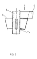
- FIG. 5 shows an embodiment of scaffold node 1 and connecting element 2 with pockets 8 welded directly onto the scaffold stand 3 and webs 6 welded directly to the spacer bar 5.
- the spacer bar is slit in the middle in the axial longitudinal direction in the insertion area of the web.
Landscapes
- Engineering & Computer Science (AREA)
- Architecture (AREA)
- Mechanical Engineering (AREA)
- Civil Engineering (AREA)
- Structural Engineering (AREA)
- Mutual Connection Of Rods And Tubes (AREA)
- Coating With Molten Metal (AREA)
Abstract
Description
Die Erfindung bezieht sich auf die konstruktive Ausführung von Gerüstbauelementen, wie Gerüstknoten und die zugehörigen Anschlußelemente für ein Modulgerüst in der Kombination Stahl und Aluminium.The invention relates to the structural design of scaffolding components, such as scaffolding nodes and the associated connection elements for a modular scaffolding in the combination of steel and aluminum.
Im Gerüstbau werden Gerüststangen als Distanzelemente in horizontaler und vertikaler Richtung mittels Knotenelementen zu dreidimensionalen Gerüstbauten in Form von Fassaden- und Raumgerüsten montiert.In scaffolding, scaffolding poles are assembled as spacer elements in horizontal and vertical directions using node elements to create three-dimensional scaffolding structures in the form of facade and room scaffolding.
Für eine preisgünstige Fertigung von Gerüstbauelementen und ihre effektive Montage bzw. Demontage sind originelle Lösungen für die Konstruktion der Knotenelemente und der Anschlußelemente gefragt.For an inexpensive manufacture of scaffolding components and their effective assembly and disassembly, original solutions for the construction of the node elements and the connecting elements are required.
Diese Elemente müssen so aufgebaut sein und in ihrem Zusammenwirken, in ihrer mechanischen Verbindung zur Aufnahme von Kräften, Lasten und Biegemomenten so harmonieren, daß alle sicherheitstechnischen Anforderungen zuverlässig erfüllt werden.These elements must be constructed and harmonize in their interaction, in their mechanical connection to absorb forces, loads and bending moments, so that all safety requirements are reliably met.
Der Stand der Technik ist durch eine Vielzahl von Gerüstbausysteme gekennzeichnet.The state of the art is characterized by a large number of scaffolding systems.
Das Gerüst mit Verbindungsvorrichtungen nach DE-OS 37 02 057 und DE-OS 38 13 513 hat Stiele aus Leichtmetallrohr mit Lochscheiben. Die Anschlußköpfe sind mit ihren Schlitzen über die Lochscheiben gesteckt und mit Keilen gesichert. Die Lochscheiben bestehen aus Leichtmetall und sind mit Hilfe von Schweißnähten festgeschweißt. Die Anschlußköpfe bestehen aus Stahlguß oder geschmiedetem Stahl. Für die Sicherung gegen Verlieren hat der Keil einen Niet oder dgl..The scaffold with connecting devices according to DE-OS 37 02 057 and DE-OS 38 13 513 has handles made of light metal tubing with perforated disks. The connector heads are slotted over the perforated washers and secured with wedges. The perforated discs are made of light metal and are welded with the help of welds. The connection heads are made of cast steel or forged steel. The wedge has a rivet or the like for securing against loss.
Weiterentwicklungen solcher als Verbindungsvorrichtungen für Gerüstelemente eingesetzte Lochscheiben sind in DE-OS 38 24 823, DE-OS 39 09 809 und DE-OS 39 34 857 beschrieben.Further developments of such perforated disks used as connecting devices for scaffolding elements are described in DE-OS 38 24 823, DE-OS 39 09 809 and DE-OS 39 34 857.
Aus FR-PS 23 52 194 ist eine Keil-Steckverbindung bekannt, bei der die Montage von Gerüstknoten und Anschlußelementen durch die Paarung keilförmiges U-Profil als Steckelement in einer paßfähig ausgebildeten in analoger Weise zum Steckelement aufwendig gestalteten Tasche erfolgt.
Am unterhalb jeder Tasche des Gerüstknotens überstehenden Ende des U-Profils sind Mittel zur Verriegung der Keil-Steck-Verbindung vorhanden. Die hier vorgeschlagene Ausbildung der Keil-Steck-Verbindung ist kompliziert und aufwendig im Aufbau; sie hat eine ungenügende vertikale Rahmenfestigkeit.From FR-PS 23 52 194 a wedge plug connection is known, in which the assembly of scaffold nodes and connecting elements is carried out by the pairing of wedge-shaped U-profile as a plug element in a suitably designed pocket in an analogous manner to the plug element.
At the end of the U-profile protruding below each pocket of the scaffold node there are means for locking the wedge-plug connection. The design of the wedge-plug connection proposed here is complicated and complex in construction; it has insufficient vertical frame strength.
In GB-PS 1 601 897 wird ein Anschlußelement mit einem geschlitzten Steg und einer sehr geringen Rahmensteifigkeit beschrieben.
Verriegelungsmöglichkeiten fehlen völlig. Die Auflagefläche für Gerüstbeläge ist ungünstig und teilweise ungeeignet ausgebildet, da die Oberkante des Distanz- bzw. Auflageriegels keine durchgängige Waagerechte ergibt.GB-
Locking options are completely missing. The support surface for scaffold coverings is unfavorable and sometimes unsuitable, since the upper edge of the spacer or support bar does not provide a continuous horizontal.
Mit DE-OS 29 49 403 wird ein Gerüst und ein zugehöriges Querelement vorgestellt. Die Enden des Querelements bzw. der rohrförmigen Strebe sind jeweils mit einem Zapfen in der Weise verbunden, daß jeder Zapfen an der rechtwinklig geformten, abgeflachten Stirnseite der Strebe durch langgestreckte Schweißnähte befestigt ist.With DE-OS 29 49 403 a scaffold and an associated cross element is presented. The ends of the cross member or the tubular strut are each connected to a pin in such a way that each pin on the right angle shaped, flattened face of the strut is attached by elongated welds.
Aufgabe der Erfindung ist es, eine bisher noch nicht erreichte vertikale Rahmensteifigkeit in der Verbindung von Gerüstknoten und Anschlußelementen durch geeignete konstruktive Maßnahmen sicherzustellen.
Das heißt, daß bei vertikaler Überlast zuerst das Gerüstrohr versagen soll, bevor an der Einspannvorrichtung (Volleinspannung) eine Verformung oder gar ein Versagen eintritt.The object of the invention is to ensure a hitherto unprecedented vertical frame rigidity in the connection of scaffold nodes and connecting elements by suitable design measures.
This means that if the vertical overload occurs, the scaffold tube should first fail before the clamping device (full clamping) is deformed or even fails.
Eine erfindungsgemäße Lösung dieser Aufgabe ist im Patentanspruch 1 angegeben. Weiterbildungen der Erfindung sind in den Unteransprüchen gekennzeichnet.An inventive solution to this problem is specified in
Das Wesen der Erfindung besteht darin, daß die prinzipiell bekannte Keil-Steck-Verbindung von Gerüstknoten und Anschlußelementen so weiterentwickelt wurde, daß die keilförmigen Steckelemente als einfache keilförmige Stege ausgebildet sind, die an beiden Enden eines jeden Distanzriegels so angeordnet sind, daß der Steg auf der Wandung des Distanzriegels oder auf einer auf jedes Distanzriegelende aufgeschobenen Hülse aufsitzend in der Art eines Querriegels befestigt ist und die keilförmigen Stege jeweils in eine mit analoger Formgebung ausgeführte Tasche eingreifen.The essence of the invention is that the principally known wedge-plug connection of scaffold nodes and connection elements has been further developed such that the wedge-shaped plug elements are designed as simple wedge-shaped webs which are arranged at both ends of each spacer bar so that the web is on is attached to the wall of the spacer bar or is seated on a sleeve pushed onto each spacer bar end in the manner of a transverse bar and the wedge-shaped webs each engage in a pocket designed with an analog shape.
Zur Verriegelung und gleichzeitigen Verspannung der Verbindungselemente Knoten und Anschlußelement(e) ist im über die Unterseite der Tasche (8) hinausragenden Stegende (7) mindestens eine Öffnung (12) zur Aufnahme von Verriegelungselementen (13) eingebracht.For locking and simultaneous bracing of the connecting elements node and connecting element (s), at least one opening (12) for receiving locking elements (13) is made in the web end (7) projecting beyond the underside of the pocket (8).
Darüberhinaus sind für Sonderfälle (Kombinationen mit Rohren und Kupplungen) zur Aufnahme horizontaler Querkräfte zwischen Gerüstständer und Anschlußelement Zusatzelemente vorhanden.In addition, additional elements are available for special cases (combinations with pipes and couplings) for absorbing horizontal transverse forces between the scaffold stand and the connecting element.
Bei einer bevorzugten Ausführungsform des Knotenelementes sind vier Taschen in Kreuzform, d.h. jeweils um 90° versetzt, an einem rohr- oder rahmenförmig ausgebildeten, mit einem Längsschlitz versehen Trägersegment befestigt, oder die Taschen sind direkt am Ständer verschweißt.In a preferred embodiment of the node element, four pockets are cross-shaped, i.e. each offset by 90 °, attached to a tubular or frame-shaped carrier segment provided with a longitudinal slot, or the pockets are welded directly to the stand.
Die Verankerung des Gerüstknotens bei der bevorzugten Ausführungsform kann in beliebiger Höhe am Gerüstständer mittels einer Spannverbindung erfolgen.
Die Taschen des Gerüstknotens weisen dabei im Querschnitt eine U-Form oder V-Form auf, wobei die Stirnseiten der beiden parallel oder V-förmig verlaufenden Schenkel einer Tasche am Trägersegment, beispielweise durch Schweißverbindung, befestigt sind.The scaffold node can be anchored in the preferred embodiment at any height on the scaffold stand by means of a clamping connection.
The pockets of the scaffold node have a U-shape or V-shape in cross-section, the end faces of the two parallel or V-shaped legs of a pocket being fastened to the carrier segment, for example by a welded connection.
Die U-Schenkel oder V-Schenkel bzw. Seitenwände der Taschen können paßfähig zur Geometrie des keilförmigen Steges trapezförmig ausgeführt sein.The U-legs or V-legs or side walls of the pockets can be trapezoidal to fit the geometry of the wedge-shaped web.
Eine bevorzugte Ausführungsform des Anschlußelementes besteht aus einem Distanzriegel und zwei an den Stirnseiten des Distanzriegels aufgebrachten Hülsen, die jeweils einen keilförmigen Steg für die Steckverbindung mit dem Gerüstknoten tragen. Die Distanzriegel selbst bestehen aus Aluminium oder Stahl, die Hülsen incl. der Stege sind aus Festigkeitsgründen nur aus Stahl gefertigt.A preferred embodiment of the connecting element consists of a spacer bar and two sleeves attached to the end faces of the spacer bar, each of which carries a wedge-shaped web for the plug connection with the scaffold node. The spacer bars themselves are made of aluminum or steel, the sleeves including the bars are only made of steel for reasons of strength.
Ein direktes Anschweißen der keilförmigen Stege in das Profil eines Distanzriegels aus Stahl ist ebenfalls möglich. Dazu kann der Distanzriegel an den Stirnseiten geschlitzt ausgeführt sein.A direct welding of the wedge-shaped webs into the profile of a steel spacer is also possible possible. For this purpose, the spacer bar can be slotted on the end faces.
Die Verbindung von Hülsen und Distanzriegeln erfolgt durch stirnseitiges Aufschieben bzw. Aufpressen und nachfolgendes punktuelles Sicken oder sonstige geeignete Maßnahmen. Zur Erleichterung des stirnseitigen Aufbringens der Hülsen auf den Distanzriegel kann die Hülse in axialer Richtung geschlitzt ausgeführt sein. In diesem Fall wird der Steg vor dem Aufpressen der Hülse auf den Distanzriegel in den Schlitz eingepaßt und/oder im Schlitzbereich mit der Hülse und/oder dem Distanzriegel verschweißt.The connection of sleeves and spacer bars is done by pushing on or pressing on the front and subsequent beading or other suitable measures. To facilitate the frontal application of the sleeves on the spacer bar, the sleeve can be slotted in the axial direction. In this case, the web is fitted into the slot before the sleeve is pressed onto the spacer bar and / or welded to the sleeve and / or the spacer bar in the slot area.
Die Anschlußelemente können rohrförmig mit Kreisprofil oder ovalem Profil, aber auch als Kasten- bzw. Preßprofile in Stahl oder Aluminium ausgeführt sein. Dabei sind die Distanzriegel aus Stahl oder Aluminium und die Hülsen incl. der Stege nur aus Stahl gefertigt.The connecting elements can be tubular with a circular profile or oval profile, but also as box or pressed profiles in steel or aluminum. The spacer bars are made of steel or aluminum and the sleeves including the bars are only made of steel.
Der Steg ragt nach vollzogener Keil-Steck-Verbindung von Anschlußelement und Gerüstknoten aus der Unterseite der jeweiligen Tasche des Gerüstknotens heraus.
In diesem überstehenden Teil des Steges, der sich außerhalb der Tasche befindet, ist mindestens eine Öffnung zur Aufnahme von Verriegelungselementen, die zur Gewährleistung der Sicherheitsanforderungen bestimmt sind, vorhanden. Derartige Verriegelungselemente sind nur bei Sonderkonstruktionen zur Verhinderung des Herausrutschens des Ständers bzw. der Ständer erforderlich.After the wedge-plug connection of the connecting element and scaffold node has been completed, the web protrudes from the underside of the respective pocket of the scaffold node.
In this projecting part of the web, which is located outside the pocket, there is at least one opening for receiving locking elements which are intended to ensure the safety requirements. Such locking elements are only required for special constructions to prevent the stand or stand from slipping out.
Zur Unterstützung der Verspannung bzw. Verkeilung der Funktionselemente Steg und Tasche bzw. Anschlußelement und Gerüstknoten schließen die Steg-Stirnseite und die Taschenunterseite einen spitzen Winkel α ein.To support the bracing or wedging of the functional elements web and pocket or connecting element and scaffold node, the web end and the underside of the pocket close an acute angle α.
Mittels dieser speziellen Geometrie wird die Voraussetzung geschaffen, daß bei Einbau der Verriegelungselemente in die im überstehenden Teil des Steges befindliche, in den Bereich der Unterkante der Tasche hineinreichende Öffnung die gewünschte Keil- und damit Spannwirkung zwischen Steg und Tasche sowie zwischen Anschlußelement und Gerüstknoten erreicht wird.By means of this special geometry, the prerequisite is created that when the locking elements are installed in the opening in the projecting part of the web, which extends into the region of the lower edge of the pocket, the desired wedge and thus tensioning effect between the web and the pocket and between the connecting element and the scaffold node is achieved .
Als Verriegelungselemente werden Keile, Kegelstifte, Kegelschrauben oder sonstige geeignete Sicherungselemente in Wechselwirkung mit der entsprechend angepaßten Öffnung im Stegende in einer die Verspannungswirkung gewährleistenden Anordnung eingesetzt.Wedges, tapered pins, tapered screws or other suitable securing elements are used as locking elements in interaction with the correspondingly adapted opening in the web end in an arrangement ensuring the tensioning effect.
Durch die keilförmige Ausbildung der Verriegelungselemente und die Keilwirkung des spitzen Winkels α zwischen Stegstirnseite und Taschenunterseite wird ein Festziehen des Steges ermöglicht, wodurch eine zusätzliche Verspannung dieses Teiles der Gerüstkonstruktion bei evtl. Erfordernis, beispielsweise für am Riegel abgehängte Ständer, gegeben ist.Due to the wedge-shaped design of the locking elements and the wedge effect of the acute angle α between the web end face and the underside of the pocket, tightening of the web is made possible, whereby additional bracing of this part of the scaffolding structure is possible if necessary, for example for stands suspended from the bolt.
Die Sicherung des Verriegelungselementes selbst erfolgt beispielsweise durch Bohrungen quer zur Längsachse bzw. Bewegungsrichtung des Verriegelungselementes in der Weise, daß in die erste Bohrung nach dem Durchtritt des Verriegelungselementes durch die dafür vorgesehene Öffnung im Stegende ein Federstecker oder ein sonstiges Sicherungselement eingesetzt wird.The locking element itself is secured, for example, by bores transverse to the longitudinal axis or direction of movement of the locking element in such a way that a spring pin or another securing element is inserted into the first bore after the locking element has passed through the opening provided in the web end.
Zur Aufnahme zusätzlicher horizontaler Querkräfte der Verbindung Anschlußelement mit Gerüstständer, z. B. Anschluß von Diagonalen oder Fensterspreizen am Riegel, kann neben der Keil-Steck-Verbindung eine zweite Arretierung und Positionierung des Anschlußelementes am Gerüstständer durchgeführt werden.To absorb additional horizontal transverse forces of the connection element with scaffold stand, z. B. Connection diagonals or window spreads on the transom, in addition to the wedge-plug connection, a second locking and positioning of the connection element on the scaffold stand can be carried out.
Dazu wird der Distanzriegel so ausgeführt, daß er quasi soweit über die Randhülse übersteht, bis die Randzonen seiner paßgerecht zum Profil des Gerüstständers ausgeformten Stirnseite den Gerüstständer teilweise umfassen.For this purpose, the spacer bar is designed so that it protrudes, as it were, beyond the edge sleeve until the edge zones of its end face which is shaped to match the profile of the scaffold stand partially surround the scaffold stand.
Diese Verlängerung des Distanzriegels kann auch als im Querschnitt dem Profil des Distanzriegels bzw. der Hülse angepaßtes Zusatzelement in die Hülse eingepreßt, geschweißt oder gesteckt sein.This extension of the spacer bar can also be pressed, welded or inserted into the sleeve as an additional element in cross section which is adapted to the profile of the spacer bar or the sleeve.
In einer anderen Ausführungsform ist die in die Hülse des Anschlußelementes eingreifende zweite Arretierung als Stutzen, beispielsweise als Rohrstutzen ausgeführt. Dieser Stutzen ist mit seiner Stirnseite an der Oberfläche des Gerüstständers anliegend mit dem Distanzriegel verschweißt oder der Stutzen ist anderweitig am Gerüstständer oder Distanzriegel befestigt.
Die Befestigung des Stutzens am Gerüstständer muß dabei in der Position erfolgen, daß bei der Montage der Stutzen in die Hülse geschoben werden kann, d.h. die Mittelachse von Stutzen und Hülse des Anschlußelementes müssen in der Einbaulage übereinstimmen.In another embodiment, the second locking device engaging in the sleeve of the connecting element is designed as a socket, for example as a pipe socket. This nozzle is welded with its end face to the surface of the scaffold stand with the spacer bar or the nozzle is otherwise attached to the scaffold stand or spacer bar.
The connection of the connector to the scaffold stand must be in the position that the connector can be pushed into the sleeve during assembly, ie the center axis of the connector and sleeve of the connecting element must match in the installed position.
Natürlich können auch beide Maßnahmen, also Stutzen am Gerüstständer und Verlängerung des Distanzriegels über die Hülse hinaus, in angepaßter Weise miteinander kombiniert werden.Of course, both measures, that is, sockets on the scaffold stand and extension of the spacer bar beyond the sleeve, can be combined with one another in an adapted manner.
Mit dieser Möglichkeit zur Aufnahme zusätzlicher horizontaler Querkräfte (Rohranschluß mit Kupplung) ist die Verbindungslösung aus Gerüstknoten und Knotenanschlußelement in der Lage, in Verlängerung der Mittelachse des Anschlußelementes Kräfte aufzunehmen, die sonst ein seitliches Verschieben, Verkanten und Verformen der keilförmigen Steckelemente oberhalb der Tasche bewirken würden.With this ability to accommodate additional horizontal Shear forces (pipe connection with coupling), the connection solution consisting of scaffold nodes and node connection element is able to absorb forces in the extension of the central axis of the connection element, which would otherwise cause the wedge-shaped plug-in elements to move, tilt and deform above the pocket.
Die mit der erfindungsgemäßen Gerüstbaukonstruktion erreichten Biegemomente und die sich daraus ergebende vertikale Rahmensteifigkeit übertreffen die analogen technischen Parameter bisher bekannter Modul-Gerüstsysteme. Durch die erreichte hohe Anschlußsteifigkeit, die statisch einer Volleinspannung gleichkommt, ergeben sich solche Vorzüge der neuen Gerüstbaukonstruktion, wie Material- und Gewichtsreduzierung, Einsparmöglichkeiten bei der Vertikalverstrebung, Kostensenkungen, Verringerung der Montagezeiten und Sonderkonstruktionsmöglichkeiten ausgehend von den gegebenen hohen Biegemomenten.The bending moments achieved with the scaffolding construction according to the invention and the resulting vertical frame rigidity exceed the analog technical parameters of previously known modular scaffolding systems. The high connection rigidity achieved, which statically equates to full clamping, results in advantages of the new scaffolding construction, such as material and weight reduction, savings in vertical bracing, cost reductions, reduced assembly times and special design options based on the given high bending moments.
Die Erfindung wird nachstehend ohne Beschränkung des allgemeinen Erfindungsgedankens anhand von Ausführungsbeispielen unter Bezugnahme auf die Zeichnung exemplarisch beschrieben, auf die im übrigen bezüglich der Offenbarung aller im Text nicht näher erläuterten erfindungsgemäßen Einzelheiten ausdrücklich verwiesen wird. Es zeigen:
- Fig. 1
- Gerüstknoten mit Anschlußelement und Verriegelungseinrichtung - als Vorderansicht;
- Fig. 2
- Gerüstknoten nach Fig. 1
- als Seitenansicht; - Fig. 3
- Gerüstknoten nach Fig. 1
- als Draufsicht; - Fig. 4
- Ausbildung der Sicherungseinrichtung in axialer Verlängerung des Anschlußelementes;
- Fig. 5
- Gerüstknoten mit direkt aufgeschweißten Taschen.
- Fig. 1
- Scaffolding node with connection element and locking device - as a front view;
- Fig. 2
- Scaffold node according to FIG. 1
- as a side view; - Fig. 3
- Scaffold node according to FIG. 1
- as a top view; - Fig. 4
- Training of the safety device in the axial extension of the connecting element;
- Fig. 5
- Scaffold knot with directly welded-on pockets.
Fig. 1 zeigt die Gesamtdarstellung des erfindungsgemäßen Gerüstknotens 1 mit einem eingezeichneten Knotenanschlußelement 2 und der Verriegelungseinrichtung 7, 13.1 shows the overall view of the
Der Gerüstknoten 1 besitzt vier kreuzförmig angeordnete Taschen 8, die an einem rohrförmigen Trägersegment 9 angeschweißt sind.The
Die Taschen 8 sind im Querschnitt U-förmig mit parallel verlaufenden Seitenwänden 18 ausgeführt, wobei die Seitenwände paßfähig zur Geometrie des im Montagefall in die Tasche eingeführten keilförmigen Steges 6 des Anschlußelementes 2 eine Trapezform besitzen.The
Der Gerüstknoten 1 ist in der gewünschten Höhe am Gerüstständer 3 verankert und mittels des keilförmigen Steges 6 sind die Anschlußelemente 2 eingehängt.
Jedes Anschlußelement 2 besteht aus einem Distanzriegel 5 und den die Stege 6 tragenden Randhülsen 4.
Die Hülsen 4 sind stirnseitig auf die Distanzriegel 5 aufgepreßt und in ihrer Position durch punktuelle Sicken 11 festgelegt.The
Each connecting
The
Werkstoffseitig wird für die Distanzriegel 5 Aluminium oder Stahl und für die Hülsen 4 sowie Stege 6 nur Stahl eingesetzt.On the material side, aluminum or steel is used for the spacer bars 5 and only steel for the
Die für die Gewährleistung der notwendigen Sonderfallkombinationen mit Rohren und Kupplungen notwendige Arretierung der Stege 6 der Anschlußelemente 2 in den Taschen 8 der Gerüstknoten 1 erfolgt durch Einbringen von Verriegelungselementen 13 in das über die Taschenunterseite 19 hinausragende Stegende 7.
Dazu ist in Höhe der Taschenunterseite 19 eine Bohrung 12 in das Stegende 7 eingearbeitet, in die als Verriegelungselement ein paßfähiger Kegelstift oder ähnliches eingeschlagen oder eingepreßt wird.The one to ensure the necessary special case combinations necessary locking of the
For this purpose, a bore 12 is machined into the
Eine weitere mit dem Anziehen des Verriegelungselementes 13 ausgenutzte Keilwirkung wird durch die spezielle Ausbildung der Taschenunterseite 19 in der Weise erreicht, daß zwischen dieser in Richtung des Trägersegments 9 aufsteigenden Taschenunterseite 19 und der Stegstirnseite ein spitzer Winkel α vorhanden ist.Another used with the tightening of the locking
In Fig. 2 ist der Gerüstknoten 1 nach Fig. 1 in einer um 90° gedrehten Seitenansicht dargestellt.FIG. 2 shows the
Zu erkennen ist die Sicherung des Verriegelungselementes 13, die dadurch erfolgt, daß quer zur Längsachse des Kegelstiftes 13 Bohrungen 14 eingebracht sind und in die erste Bohrung nach Durchtritt des Kegelstiftes ein Federstecker 15 eingeführt werden kann.The securing of the locking
Die Verankerung des Gerüstknotens 1 in einer beliebigen Höhe des Gerüstständers 3 ist aus Fig. 3 - einer Draufsicht auf einen montierten Gerüstknoten - ersichtlich. Zu diesem Zweck ist das Trägersegment 9 mit einem Längsschlitz versehen und am Trägersegment ist eine Spannvorrichtung 10 vorhanden.The anchoring of the
Fig. 4 veranschaulicht zwei Ausführungsformen zur Aufnahme zusätzlicher Querkräfte am keilförmigen Steg (6) oberhalb der Tasche (8) und deren Ableitung in den Gerüstständer (3).Fig. 4 illustrates two embodiments for recording Additional transverse forces on the wedge-shaped web (6) above the pocket (8) and their derivation in the scaffold stand (3).
Diese zusätzliche für den Sonderfall vorgesehene Einrichtung (Kombination mit Rohren und Kupplungen) dient zur Arretierung und Positionierung des Anschlußelementes 2 am Gerüstständer 3 und greift in axialer Verlängerung des Anschlußelementes mittels eines Zusatzelementes 16, 17 am Gerüstständer 3 an.This additional device provided for the special case (combination with pipes and couplings) serves to lock and position the
In Fig. 4.1 ist dieses Zusatzelement 16 durch ein in die Hülse 4 stirnseitig eingestecktes oder eingepreßtes Rohrstück realisiert. Die zum Gerüstständer 3 weisende Stirnseite des Rohrstücks ist dabei so ausgeformt, daß sie am Gerüstständer anliegt und diesen dabei teilweise umschließt.In Fig. 4.1, this
In einer anderen Ausführungsvariante nach Fig. 4.2 ist der zum Zwecke der zusätzlichen Arretierung des Anschlußelementes 2 am Gerüstständer 3 in die Hülse 4 eintauchende Stutzen 17 mit dem Distanzriegel verschweißt.
In der Einbaulage stimmen die Längsachse des Rohrstutzens 17 mit der Längsachse des Anschlußelementes 2 überein.In another embodiment variant according to FIG. 4.2, the connecting
In the installed position, the longitudinal axis of the
Fig. 5 zeigt eine Ausführungsform von Gerüstknoten 1 und Anschlußelement 2 mit direkt auf dem Gerüstständer 3 aufgeschweißten Taschen 8 und direkt mit dem Distanzriegel 5 verschweißten Stegen 6. Der Distanzriegel ist an den Stirnseiten mittig in axialer Längsrichtung im Einschubbereich des Steges geschlitzt ausgeführt.5 shows an embodiment of
Claims (10)
dadurch gekennzeichnet, daß die keilförmigen Steckelemente als einfache keilförmige Stege (6) ausgebildet sind, die an beiden Enden eines jeden Distanzriegels (5) so angeordnet sind, daß der Steg (6) auf der Wandung des Distanzriegels (5) oder auf einer auf jedes Distanzriegelende aufgeschobenen Hülse (4) aufsitzend in der Art eines Querriegels befestigt ist und die keilförmigen Stege jeweils in eine mit analoger Formgebung ausgeführten Tasche (8) eingreifen
und bei Erfordernis zur Verriegelung und gleichzeitigen Verspannung der Verbindungselemente Knoten (1) und Knotenanschlußelement (2) im über die Unterseite der Tasche (8) hinausragenden Stegende (7) mindestens eine Öffnung (12) zur Aufnahme von Verriegelungselementen (13) eingebracht ist, wobei zwischen der Stirnseite (20) des Steges (6) und der Unterseite (19) der Tasche (8) ein spitzer Winkel α vorhanden ist
und darüberhinaus zur Aufnahme zusätzlicher horizontaler Querkräfte zwischen Gerüstständer (3) und jeweiligem Anschlußelement (2) Zusatzelemente (16,17) zu ihrer Kopplung und damit Arretierung vorgesehen sind.Knot and knot connection element for scaffolding systems with a star-shaped knot element (1), which has four pockets (8), into which wedge-shaped plug elements (6) engage, which are fastened in the edge area of the connection elements (2) in the longitudinal direction and at right angles to the longitudinal axis of the connection elements,
characterized in that the wedge-shaped plug-in elements are designed as simple wedge-shaped webs (6) which are arranged at both ends of each spacer bar (5) such that the web (6) on the wall of the spacer bar (5) or on one on each The spacer bar end of the pushed-on sleeve (4) is fastened in the manner of a cross bar and the wedge-shaped webs each engage in a pocket (8) with an analog shape
and if required for locking and simultaneous bracing of the connecting elements knot (1) and knot connecting element (2) in the web (8) protruding beyond the bottom (7) at least one opening (12) for receiving locking elements (13) is introduced, wherein an acute angle α is present between the end face (20) of the web (6) and the underside (19) of the pocket (8)
and in addition to absorb additional horizontal transverse forces between the scaffold stand (3) and the respective connecting element (2) additional elements (16, 17) are provided for their coupling and thus locking.
dadurch gekennzeichnet, daß jedes Knotenelement (1) aus einem paßfähig zum Querschnitt der Gerüstständer (3) und Anschlußelemente (2) rohrförmig oder mit anderem Querschnitt ausgebildeten mit einem Längsschlitz und einer Spannverbindung (10) versehenen Trägersegment (9) aufgebaut ist, und die vier Taschen (8) auf dem Trägersegment (9) befestigt sind.Node and node connection element according to claim 1,
characterized in that each node element (1) from a suitable to the cross section of the scaffold stand (3) and Connection elements (2) tubular or with a different cross-section with a longitudinal slot and a clamping connection (10) provided support segment (9) is constructed, and the four pockets (8) are attached to the support segment (9).
dadurch gekennzeichnet, daß die Seitenwände (18) der Taschen (8) eine Trapezform besitzen, d.h. mit in Richtung zur Unterseite (19) der Tasche (8) abnehmenden Abstand des Taschenbodens zum Trägersegment (9) hin ausgebildet sind.Node and node connection element according to claim 1 or 2,
characterized in that the side walls (18) of the pockets (8) have a trapezoidal shape, ie are designed with a decreasing distance from the pocket bottom to the carrier segment (9) towards the underside (19) of the pocket (8).
dadurch gekennzeichnet, daß bei direkter Verbindung des jeweiligen Steges (6) mit dem Distanzriegel (5) der Distanzriegel im Einschubbereich des Steges in axialer Längsrichtung geschlitzt ausgeführt ist.Node and node connection element according to claim 1,
characterized in that when the respective web (6) is directly connected to the spacer bar (5), the spacer bar in the insertion region of the web is slotted in the axial longitudinal direction.
dadurch gekennzeichnet, daß die Randhülsen (4) mit den Stegen (6) auf die Distanzriegel (5) stirnseitig aufgeschoben und verschweißt oder aufgepreßt sind und durch nachfolgendes punktuelles Sicken (11) oder sonstige geeignete Maßnahmen zuverlässig arretiert sind.Node and node connection element according to claim 1,
characterized in that the edge sleeves (4) with the webs (6) are pushed onto the front side of the spacer bars (5) and are welded or pressed on and are reliably locked by subsequent puncturing (11) or other suitable measures.
dadurch gekennzeichnet, daß die Hülsen (4) in axialer Richtung geschlitzt ausgeführt sind und der Steg (6) nach erfolger Verbindung im Bereich des Schlitzes angeordnet ist.Node and node connection element according to claim 5,
characterized in that the sleeves (4) are slotted in the axial direction and the web (6) is arranged in the area of the slot after successful connection.
dadurch gekennzeichnet, daß zur Sicherung des jeweiligen Verriegelungselementes (13) Bohrungen (14) quer zur Längsachse bzw. Bewegungsrichtung des Verriegelungselementes eingebracht sind und, daß im Einbauzustand die erste Bohrung nach dem Durchtritt des Verriegelungselementes (13) durch die in das Stegende (7) eingebrachte Öffnung (12) einen Federstecker (15) oder ein sonstiges Sicherungselement bei Erfordernis aufnehmen kann.Node and node connection element according to claim 1,
characterized in that to secure the respective locking element (13) bores (14) transverse to Longitudinal axis or direction of movement of the locking element are introduced and that in the installed state, the first hole after the passage of the locking element (13) through the opening in the web (7) opening (12) can accommodate a spring pin (15) or other securing element if necessary .
dadurch gekennzeichnet, daß eine zusätzliche Arretierung des Anschlußelementes (2) am Gerüstständer (3) dadurch erfolgt, daß der Distanzriegel (5) soweit in Richtung Gerüstständer (3) über die Randhülse (4) übersteht, daß er mit den Randzonen seiner paßgerecht zum Profil des Gerüstständers (3) ausgeformten Stirnseite den Gerüstständer umfaßt.Node and node connection element according to one of claims 1 to 7,
characterized in that the connecting element (2) is additionally locked on the scaffold stand (3) in that the spacer bar (5) projects so far in the direction of the scaffold stand (3) over the edge sleeve (4) that it fits the profile with the edge zones thereof of the scaffold stand (3) formed front comprises the scaffold stand.
dadurch gekennzeichnet, daß die Verlängerung des Distanzriegels (5) als im Querschnitt dem Profil des Distanzriegels bzw. der Hülse (4) angepaßtes Zusatzelement (16) in die Hülse eingebracht ist.Node and node connection element according to claim 8,
characterized in that the extension of the spacer bar (5) is introduced into the sleeve as an additional element (16) adapted in cross section to the profile of the spacer bar or the sleeve (4).
dadurch gekennzeichnet, daß die in die Hülse (4) eingreifende zusätzliche Arretierung als Stutzen (17) ausgeführt ist, der mit seiner Stirnseite an der Oberfläche des Gerüstständers (3) anliegend mit dem Distanzriegel (5) verschweißt ist.Node and node connection element according to claims 1 and 8,
characterized in that the additional locking device engaging in the sleeve (4) is designed as a connecting piece (17) which is welded with its end face to the surface of the scaffolding stand (3) with the spacer bar (5).
Applications Claiming Priority (2)
| Application Number | Priority Date | Filing Date | Title |
|---|---|---|---|
| DE4314001A DE4314001C2 (en) | 1993-04-29 | 1993-04-29 | Scaffolding knot |
| DE4314001 | 1993-04-29 |
Publications (2)
| Publication Number | Publication Date |
|---|---|
| EP0622504A1 true EP0622504A1 (en) | 1994-11-02 |
| EP0622504B1 EP0622504B1 (en) | 1997-06-18 |
Family
ID=6486651
Family Applications (1)
| Application Number | Title | Priority Date | Filing Date |
|---|---|---|---|
| EP94106159A Expired - Lifetime EP0622504B1 (en) | 1993-04-29 | 1994-04-21 | Joint and jointing element for scaffolding system |
Country Status (3)
| Country | Link |
|---|---|
| EP (1) | EP0622504B1 (en) |
| AT (1) | ATE154660T1 (en) |
| DE (2) | DE4314001C2 (en) |
Cited By (4)
| Publication number | Priority date | Publication date | Assignee | Title |
|---|---|---|---|---|
| WO2010142797A1 (en) * | 2009-06-12 | 2010-12-16 | G.M.B. Trade And Service Company Ltd. | Latticework modular scaffolding system |
| CN106958347A (en) * | 2017-05-16 | 2017-07-18 | 杨秀峰 | Self-locking socket joint keyway cross bar |
| CN108517961A (en) * | 2018-05-25 | 2018-09-11 | 夏念涛 | A kind of direct insertion installation node of quick assembling beam column of steel structure and its installation method |
| EP3722059A3 (en) * | 2019-03-21 | 2020-12-23 | Stetter GMBH | Mixing installation and housing for a mixing plant |
Families Citing this family (2)
| Publication number | Priority date | Publication date | Assignee | Title |
|---|---|---|---|---|
| DE102011001908A1 (en) | 2011-04-08 | 2012-10-11 | G.M.B. Trade And Service Company Ltd. | Connection element for a wedge pocket module framework system |
| DE202017102638U1 (en) | 2017-05-03 | 2017-09-21 | Hennadii Oleksandrovych Rybak | Fisherman's three-dimensional mobile modular scaffolding trade fair system |
Citations (5)
| Publication number | Priority date | Publication date | Assignee | Title |
|---|---|---|---|---|
| FR1093342A (en) * | 1955-05-03 | |||
| FR2352194A1 (en) * | 1976-05-19 | 1977-12-16 | Entrepose | Two piece detachable safety coupling for scaffolding - has male elements, on jointing members, with slotted flanks protruding through female element and jammed tight by tapered cotter pin |
| GB2073355A (en) * | 1980-03-27 | 1981-10-14 | Select Etem Sa | Framework joint for scaffolding etc |
| FR2480836A1 (en) * | 1980-04-16 | 1981-10-23 | Entrepose | Connector for tubular rods such as scaffolding poles - has two hinged halves locked about pole with wedge key bolt |
| GB1601897A (en) * | 1978-05-25 | 1981-11-04 | Press Components Ltd | Scaffolding fixings |
Family Cites Families (5)
| Publication number | Priority date | Publication date | Assignee | Title |
|---|---|---|---|---|
| FR1332686A (en) * | 1962-06-06 | 1963-07-19 | Lorba | Connection for tubular structural elements |
| GB1488170A (en) * | 1974-12-06 | 1977-10-05 | Evans & Sons Ltd C | Supporting collar for use with builders scaffolding |
| ZA786869B (en) * | 1978-12-07 | 1980-03-26 | Form Scaff Pty Ltd | Improvements in or relating to scaffolding |
| SE423735B (en) * | 1979-10-19 | 1982-05-24 | Goeteborg Staellningsgruppen | DEVICE FOR CONNECTING SIDE-ORIENTED POSITION ELEMENTS WITH STANDS IN A BUILDING POSITION OR LIKE |
| DE3429630C2 (en) * | 1984-08-11 | 1986-11-20 | Peri-Werk Artur Schwörer GmbH & Co KG, 7912 Weißenhorn | Cross brace for stacking tower |
-
1993
- 1993-04-29 DE DE4314001A patent/DE4314001C2/en not_active Expired - Fee Related
-
1994
- 1994-04-21 AT AT94106159T patent/ATE154660T1/en active
- 1994-04-21 DE DE59403153T patent/DE59403153D1/en not_active Expired - Lifetime
- 1994-04-21 EP EP94106159A patent/EP0622504B1/en not_active Expired - Lifetime
Patent Citations (5)
| Publication number | Priority date | Publication date | Assignee | Title |
|---|---|---|---|---|
| FR1093342A (en) * | 1955-05-03 | |||
| FR2352194A1 (en) * | 1976-05-19 | 1977-12-16 | Entrepose | Two piece detachable safety coupling for scaffolding - has male elements, on jointing members, with slotted flanks protruding through female element and jammed tight by tapered cotter pin |
| GB1601897A (en) * | 1978-05-25 | 1981-11-04 | Press Components Ltd | Scaffolding fixings |
| GB2073355A (en) * | 1980-03-27 | 1981-10-14 | Select Etem Sa | Framework joint for scaffolding etc |
| FR2480836A1 (en) * | 1980-04-16 | 1981-10-23 | Entrepose | Connector for tubular rods such as scaffolding poles - has two hinged halves locked about pole with wedge key bolt |
Cited By (4)
| Publication number | Priority date | Publication date | Assignee | Title |
|---|---|---|---|---|
| WO2010142797A1 (en) * | 2009-06-12 | 2010-12-16 | G.M.B. Trade And Service Company Ltd. | Latticework modular scaffolding system |
| CN106958347A (en) * | 2017-05-16 | 2017-07-18 | 杨秀峰 | Self-locking socket joint keyway cross bar |
| CN108517961A (en) * | 2018-05-25 | 2018-09-11 | 夏念涛 | A kind of direct insertion installation node of quick assembling beam column of steel structure and its installation method |
| EP3722059A3 (en) * | 2019-03-21 | 2020-12-23 | Stetter GMBH | Mixing installation and housing for a mixing plant |
Also Published As
| Publication number | Publication date |
|---|---|
| DE59403153D1 (en) | 1997-07-24 |
| DE4314001C2 (en) | 1996-05-09 |
| EP0622504B1 (en) | 1997-06-18 |
| ATE154660T1 (en) | 1997-07-15 |
| DE4314001A1 (en) | 1994-11-03 |
Similar Documents
| Publication | Publication Date | Title |
|---|---|---|
| DE60020075T2 (en) | CONNECTION DEVICE | |
| EP1005598B1 (en) | Trelliswork modular scaffolding system | |
| DE1659550C3 (en) | railing | |
| EP0622504B1 (en) | Joint and jointing element for scaffolding system | |
| EP0369153B1 (en) | Device for connecting additional elements to forming panels | |
| DE10225403B4 (en) | studding | |
| DE19703558B4 (en) | Bar equipment for a scaffolding system | |
| DE69107935T2 (en) | Scaffolding structures. | |
| EP0443111B1 (en) | Fastener to attach a column to a tubular bar, attached column and assembly with at least a column and a bar | |
| EP0851074B1 (en) | Scaffolding for platform, staging or floorshuttering | |
| EP0317695B1 (en) | Metal scaffolding for buildings | |
| EP1288392B1 (en) | Support structure for the bearing system of a stage, a podium, a scaffold construction or similar | |
| DE9212546U1 (en) | Tubular frame | |
| DE2940030C2 (en) | Junction point for detachable rigid corner connections of bars | |
| DE9306437U1 (en) | Nodes and node connection elements for scaffolding systems | |
| DE2320515A1 (en) | CONSTRUCTION ELEMENT FOR ASSEMBLING PIPES | |
| EP1300521B1 (en) | Connecting device for a wooden mullion-transom connection | |
| EP0116303B1 (en) | Lattice truss for tunnelling | |
| DE3335444C2 (en) | Connection between a drawbar and an axle | |
| EP0356685B1 (en) | Fire-resistant partition wall made of plug-in type load-bearing metal profiles | |
| WO2024240934A1 (en) | Railing bar for a scaffold and method for erecting a scaffold | |
| AT406399B (en) | SCAFFOLDING | |
| DE29821290U1 (en) | Movable guidance system | |
| DE102021121380A1 (en) | shock clamp | |
| DE2346882A1 (en) | LOCALIZATION AND SECURITY MEANS |
Legal Events
| Date | Code | Title | Description |
|---|---|---|---|
| PUAI | Public reference made under article 153(3) epc to a published international application that has entered the european phase |
Free format text: ORIGINAL CODE: 0009012 |
|
| AK | Designated contracting states |
Kind code of ref document: A1 Designated state(s): AT BE CH DE DK ES FR GB GR IT LI LU NL PT SE |
|
| 17P | Request for examination filed |
Effective date: 19950331 |
|
| 17Q | First examination report despatched |
Effective date: 19951129 |
|
| GRAG | Despatch of communication of intention to grant |
Free format text: ORIGINAL CODE: EPIDOS AGRA |
|
| GRAG | Despatch of communication of intention to grant |
Free format text: ORIGINAL CODE: EPIDOS AGRA |
|
| GRAH | Despatch of communication of intention to grant a patent |
Free format text: ORIGINAL CODE: EPIDOS IGRA |
|
| RAP1 | Party data changed (applicant data changed or rights of an application transferred) |
Owner name: MERKEL, GERALD |
|
| GRAH | Despatch of communication of intention to grant a patent |
Free format text: ORIGINAL CODE: EPIDOS IGRA |
|
| GRAA | (expected) grant |
Free format text: ORIGINAL CODE: 0009210 |
|
| AK | Designated contracting states |
Kind code of ref document: B1 Designated state(s): AT BE CH DE DK ES FR GB GR IT LI LU NL PT SE |
|
| PG25 | Lapsed in a contracting state [announced via postgrant information from national office to epo] |
Ref country code: NL Free format text: LAPSE BECAUSE OF FAILURE TO SUBMIT A TRANSLATION OF THE DESCRIPTION OR TO PAY THE FEE WITHIN THE PRESCRIBED TIME-LIMIT Effective date: 19970618 Ref country code: IT Free format text: LAPSE BECAUSE OF FAILURE TO SUBMIT A TRANSLATION OF THE DESCRIPTION OR TO PAY THE FEE WITHIN THE PRESCRIBED TIME-LIMIT;WARNING: LAPSES OF ITALIAN PATENTS WITH EFFECTIVE DATE BEFORE 2007 MAY HAVE OCCURRED AT ANY TIME BEFORE 2007. THE CORRECT EFFECTIVE DATE MAY BE DIFFERENT FROM THE ONE RECORDED. Effective date: 19970618 Ref country code: GR Free format text: LAPSE BECAUSE OF FAILURE TO SUBMIT A TRANSLATION OF THE DESCRIPTION OR TO PAY THE FEE WITHIN THE PRESCRIBED TIME-LIMIT Effective date: 19970618 Ref country code: ES Free format text: THE PATENT HAS BEEN ANNULLED BY A DECISION OF A NATIONAL AUTHORITY Effective date: 19970618 Ref country code: DK Effective date: 19970618 |
|
| REF | Corresponds to: |
Ref document number: 154660 Country of ref document: AT Date of ref document: 19970715 Kind code of ref document: T |
|
| REG | Reference to a national code |
Ref country code: CH Ref legal event code: EP |
|
| REF | Corresponds to: |
Ref document number: 59403153 Country of ref document: DE Date of ref document: 19970724 |
|
| GBT | Gb: translation of ep patent filed (gb section 77(6)(a)/1977) |
Effective date: 19970729 |
|
| REG | Reference to a national code |
Ref country code: CH Ref legal event code: NV Representative=s name: OK PAT AG |
|
| PG25 | Lapsed in a contracting state [announced via postgrant information from national office to epo] |
Ref country code: SE Effective date: 19970918 Ref country code: PT Effective date: 19970918 |
|
| ET | Fr: translation filed | ||
| NLV1 | Nl: lapsed or annulled due to failure to fulfill the requirements of art. 29p and 29m of the patents act | ||
| PG25 | Lapsed in a contracting state [announced via postgrant information from national office to epo] |
Ref country code: LU Free format text: LAPSE BECAUSE OF NON-PAYMENT OF DUE FEES Effective date: 19980421 |
|
| PLBE | No opposition filed within time limit |
Free format text: ORIGINAL CODE: 0009261 |
|
| STAA | Information on the status of an ep patent application or granted ep patent |
Free format text: STATUS: NO OPPOSITION FILED WITHIN TIME LIMIT |
|
| PG25 | Lapsed in a contracting state [announced via postgrant information from national office to epo] |
Ref country code: BE Free format text: LAPSE BECAUSE OF NON-PAYMENT OF DUE FEES Effective date: 19980430 |
|
| 26N | No opposition filed | ||
| BERE | Be: lapsed |
Owner name: MERKEL GERALD Effective date: 19980430 |
|
| REG | Reference to a national code |
Ref country code: GB Ref legal event code: IF02 |
|
| PGFP | Annual fee paid to national office [announced via postgrant information from national office to epo] |
Ref country code: FR Payment date: 20110427 Year of fee payment: 18 Ref country code: CH Payment date: 20110421 Year of fee payment: 18 Ref country code: DE Payment date: 20110418 Year of fee payment: 18 |
|
| PGFP | Annual fee paid to national office [announced via postgrant information from national office to epo] |
Ref country code: AT Payment date: 20110418 Year of fee payment: 18 Ref country code: GB Payment date: 20110419 Year of fee payment: 18 |
|
| REG | Reference to a national code |
Ref country code: CH Ref legal event code: PL |
|
| REG | Reference to a national code |
Ref country code: AT Ref legal event code: MM01 Ref document number: 154660 Country of ref document: AT Kind code of ref document: T Effective date: 20120421 |
|
| GBPC | Gb: european patent ceased through non-payment of renewal fee |
Effective date: 20120421 |
|
| REG | Reference to a national code |
Ref country code: FR Ref legal event code: ST Effective date: 20121228 |
|
| PG25 | Lapsed in a contracting state [announced via postgrant information from national office to epo] |
Ref country code: LI Free format text: LAPSE BECAUSE OF NON-PAYMENT OF DUE FEES Effective date: 20120430 Ref country code: GB Free format text: LAPSE BECAUSE OF NON-PAYMENT OF DUE FEES Effective date: 20120421 Ref country code: AT Free format text: LAPSE BECAUSE OF NON-PAYMENT OF DUE FEES Effective date: 20120421 Ref country code: CH Free format text: LAPSE BECAUSE OF NON-PAYMENT OF DUE FEES Effective date: 20120430 |
|
| REG | Reference to a national code |
Ref country code: DE Ref legal event code: R119 Ref document number: 59403153 Country of ref document: DE Effective date: 20121101 |
|
| PG25 | Lapsed in a contracting state [announced via postgrant information from national office to epo] |
Ref country code: FR Free format text: LAPSE BECAUSE OF NON-PAYMENT OF DUE FEES Effective date: 20120430 |
|
| PG25 | Lapsed in a contracting state [announced via postgrant information from national office to epo] |
Ref country code: DE Free format text: LAPSE BECAUSE OF NON-PAYMENT OF DUE FEES Effective date: 20121101 |