EP0498586A1 - Prosthesis for knee replacement - Google Patents
Prosthesis for knee replacement Download PDFInfo
- Publication number
- EP0498586A1 EP0498586A1 EP92300878A EP92300878A EP0498586A1 EP 0498586 A1 EP0498586 A1 EP 0498586A1 EP 92300878 A EP92300878 A EP 92300878A EP 92300878 A EP92300878 A EP 92300878A EP 0498586 A1 EP0498586 A1 EP 0498586A1
- Authority
- EP
- European Patent Office
- Prior art keywords
- anterior
- component
- tibial
- plastics
- femoral
- Prior art date
- Legal status (The legal status is an assumption and is not a legal conclusion. Google has not performed a legal analysis and makes no representation as to the accuracy of the status listed.)
- Granted
Links
Images


Classifications
-
- A—HUMAN NECESSITIES
- A61—MEDICAL OR VETERINARY SCIENCE; HYGIENE
- A61F—FILTERS IMPLANTABLE INTO BLOOD VESSELS; PROSTHESES; DEVICES PROVIDING PATENCY TO, OR PREVENTING COLLAPSING OF, TUBULAR STRUCTURES OF THE BODY, e.g. STENTS; ORTHOPAEDIC, NURSING OR CONTRACEPTIVE DEVICES; FOMENTATION; TREATMENT OR PROTECTION OF EYES OR EARS; BANDAGES, DRESSINGS OR ABSORBENT PADS; FIRST-AID KITS
- A61F2/00—Filters implantable into blood vessels; Prostheses, i.e. artificial substitutes or replacements for parts of the body; Appliances for connecting them with the body; Devices providing patency to, or preventing collapsing of, tubular structures of the body, e.g. stents
- A61F2/02—Prostheses implantable into the body
- A61F2/30—Joints
- A61F2/38—Joints for elbows or knees
- A61F2/3868—Joints for elbows or knees with sliding tibial bearing
-
- A—HUMAN NECESSITIES
- A61—MEDICAL OR VETERINARY SCIENCE; HYGIENE
- A61F—FILTERS IMPLANTABLE INTO BLOOD VESSELS; PROSTHESES; DEVICES PROVIDING PATENCY TO, OR PREVENTING COLLAPSING OF, TUBULAR STRUCTURES OF THE BODY, e.g. STENTS; ORTHOPAEDIC, NURSING OR CONTRACEPTIVE DEVICES; FOMENTATION; TREATMENT OR PROTECTION OF EYES OR EARS; BANDAGES, DRESSINGS OR ABSORBENT PADS; FIRST-AID KITS
- A61F2/00—Filters implantable into blood vessels; Prostheses, i.e. artificial substitutes or replacements for parts of the body; Appliances for connecting them with the body; Devices providing patency to, or preventing collapsing of, tubular structures of the body, e.g. stents
- A61F2/02—Prostheses implantable into the body
- A61F2/30—Joints
- A61F2002/30001—Additional features of subject-matter classified in A61F2/28, A61F2/30 and subgroups thereof
- A61F2002/30316—The prosthesis having different structural features at different locations within the same prosthesis; Connections between prosthetic parts; Special structural features of bone or joint prostheses not otherwise provided for
- A61F2002/30329—Connections or couplings between prosthetic parts, e.g. between modular parts; Connecting elements
- A61F2002/30383—Connections or couplings between prosthetic parts, e.g. between modular parts; Connecting elements made by laterally inserting a protrusion, e.g. a rib into a complementarily-shaped groove
- A61F2002/3039—Connections or couplings between prosthetic parts, e.g. between modular parts; Connecting elements made by laterally inserting a protrusion, e.g. a rib into a complementarily-shaped groove with possibility of relative movement of the rib within the groove
- A61F2002/30398—Sliding
-
- A—HUMAN NECESSITIES
- A61—MEDICAL OR VETERINARY SCIENCE; HYGIENE
- A61F—FILTERS IMPLANTABLE INTO BLOOD VESSELS; PROSTHESES; DEVICES PROVIDING PATENCY TO, OR PREVENTING COLLAPSING OF, TUBULAR STRUCTURES OF THE BODY, e.g. STENTS; ORTHOPAEDIC, NURSING OR CONTRACEPTIVE DEVICES; FOMENTATION; TREATMENT OR PROTECTION OF EYES OR EARS; BANDAGES, DRESSINGS OR ABSORBENT PADS; FIRST-AID KITS
- A61F2/00—Filters implantable into blood vessels; Prostheses, i.e. artificial substitutes or replacements for parts of the body; Appliances for connecting them with the body; Devices providing patency to, or preventing collapsing of, tubular structures of the body, e.g. stents
- A61F2/02—Prostheses implantable into the body
- A61F2/30—Joints
- A61F2/30767—Special external or bone-contacting surface, e.g. coating for improving bone ingrowth
- A61F2/30771—Special external or bone-contacting surface, e.g. coating for improving bone ingrowth applied in original prostheses, e.g. holes or grooves
- A61F2002/30878—Special external or bone-contacting surface, e.g. coating for improving bone ingrowth applied in original prostheses, e.g. holes or grooves with non-sharp protrusions, for instance contacting the bone for anchoring, e.g. keels, pegs, pins, posts, shanks, stems, struts
-
- A—HUMAN NECESSITIES
- A61—MEDICAL OR VETERINARY SCIENCE; HYGIENE
- A61F—FILTERS IMPLANTABLE INTO BLOOD VESSELS; PROSTHESES; DEVICES PROVIDING PATENCY TO, OR PREVENTING COLLAPSING OF, TUBULAR STRUCTURES OF THE BODY, e.g. STENTS; ORTHOPAEDIC, NURSING OR CONTRACEPTIVE DEVICES; FOMENTATION; TREATMENT OR PROTECTION OF EYES OR EARS; BANDAGES, DRESSINGS OR ABSORBENT PADS; FIRST-AID KITS
- A61F2220/00—Fixations or connections for prostheses classified in groups A61F2/00 - A61F2/26 or A61F2/82 or A61F9/00 or A61F11/00 or subgroups thereof
- A61F2220/0025—Connections or couplings between prosthetic parts, e.g. between modular parts; Connecting elements
Definitions
- the present invention provides two approaches to a solution of this dilemma.
- First, it provides a femoral component which alters the sagittal radius and which has continuous contact surfaces for the tibial surface and also, preferably, with the patella surface.
- the invention relates to a sliding bearing type of prosthesis where guide tracks for the tibial bearing surface are curved in the sagittal plane to provide the necessary stability, as well as freedom for translational motion in the anterior-posterior direction.
- the above two broad concepts may be combined in a single prosthesis or employed individually depending on the requirements of a particular case.
- the invention also includes variations of the above concepts and various designs of tibial components.
- the tibial bearing surface when viewed in one or more sagittal sections, has a radius of curvature which substantially corresponds with the radius of the bearing surface of the femoral component.
- the profiles of the sagittal sections may be slightly smaller than the radii of the corresponding sections of the tibial bearing surface, so as to allow sufficient clearance for taking up differences in surgical placement of the two components of the prosthesis, and allowing adequate laxity for normal functions.
- the femoral component portion which encases the resected condyles may be formed with a slot to permit passage of the ligaments.
- the femoral component may be continued in the distal/posterior region across the full width, i.e in the lateral-medial direction.
- the extent to which the constant radius of the femoral component in sagittal planes extends around the distalmost point is the amount sufficient to give the desired degree of flexion of the joint.
- Conformity of the femoral and tibial bearing surfaces during all stages of flexion gives increased contact area between the metal and plastic bearing surfaces, leading to reduced wear and deformation. Also, as the sagittal curvature of the tibial component is upwardly concave, the up-sweep of the tibial bearing surface posteriorly and anteriorly gives increased stability in anterior-posterior, medial-lateral and internal-external rotations. Close contact between the patella (whether natural or artificial) with the patella groove during all stages of flexion also contributes to greater stability of the joint.
- the cylindrical bearing surface between the plastics component and the metal platform viewed in a sagittal plane constrains the movement in the anterior-posterior direction. Also, the upwardly curved interface between the plastics component and the metal platform introduces increasing constraint due to gravity forces as the plastics bearing component displaces further away from its central position.
- the knee displays both laxity (which can be termed freedom of motion) and stability, which is the control of displacements and rotations to within acceptable limits.
- Laxity can include linear or rotational translation in any of the three mutually perpendicular coordinate axes.
- laxity is only considered in anterior-posterior displacement, medial-lateral displacement and internal-external rotation, these being the most significant.
- the anterior-posterior stability is provided mainly by the cruciate ligaments.
- the anterior cruciate 5 can be seen in Figure 1, especially at the higher flexion angles.
- Rotational stability is provided by a combination of the cruciate and collateral ligaments.
- the muscles also play an important role in providing stability.
- the joint surfaces contribute to stability as force is applied across the joint, due to the slight dishing of the surfaces and the deformability of the articular cartilage.
- the laxity is due to the elastic extensibility of the ligaments, the joint surfaces, and other soft tissues surrounding the joint.
- a femoral component 20 is attached to the end of the femur and a tibial component 21 to the upper part of the tibia.
- the ends of the femoral condyles are resected and shaped to receive the femoral component and held in place with bone cement and/or pegs extending into the condyles.
- the collateral and cruciate ligaments can be preserved by providing a slot 22 in the femoral component, although in most designs, either the anterior is resected, or both cruciates are resected.
- FIG. 3(a) A typical femoral component in accordance with the invention is shown in Figure 3(a).
- the condylar surfaces 31 resemble the anatomical, especially in the sagittal view, and there is a cut-out or slot 32 for one or both cruciate ligaments.
- a patella groove 33 is continuous down to the cut-out 32 after which it splits.
- the larger femoral component in Figure 3(b) now has continuous surfaces throughout, including the patella groove, but is otherwise the same. Such a configuration requires resection of both cruciate ligaments.
- the femoral shape is then used to computer-generate a tibial surface 35, based on input laxity requirements in anterior-posterior displacement and internal-external rotation.
- FIG. 5 An improvement to the patello-femoral contact is apparent from Figure 5.
- the normal dome-shape (Figure 5(a)) has high conformity when seen in the overhead view ( Figure 6), but low conformity in the sagittal view.
- Figure 5(b) and 5(c) Several experimental and theoretical studies has shown that the angle through which the patella rotates relative to the femoral component in the sagittal plane is within 10 degrees ( Figure 5(b) and 5(c)). This means that a high degree of conformity can be desired into the patella with no loss in freedom of motion.
- the new sagittal profile of the patella is shown dotted in figure 5(d).
- the above design form in accordance with the invention is most suitable when the anterior and posterior cruciate ligaments are resected.
- anterior-posterior laxity approximately 5 mm total
- rotational laxity (+ - 12 degrees
- Such laxity will also be sufficient for activities of everyday living.
- the disadvantage is that the components are relied upon for stability, and in the long run, this may lead to problems with the fixation of the components to the bone.
- resection of the cruciates is believed to reduce the proprioceptive response of the knee with consequent compensatory gait patterns.
- a further disadvantage is that extremes of motion which occur during more demanding activities may be restricted, a possible disadvantage to younger or active patients.
- One further improvement provided by the present invention is to provide for sufficient anterior-posterior and rotational stability so that the prosthesis can be used with or without the cruciate ligaments, and to provide complete femoral-tibial conformity throughout the entire range of flexion.
- it consists of making the polished metal platform for supporting the plastic bearing piece or pieces concave when seen in the sagittal view. The effect will be to offer steadily increasing resistance to displacement away from the neutral position.
- the stability and laxity characteristics can be made similar to that of a normal knee, or to a usual type of condylar prosthesis.
- Figure 7(a) shows the overall arrangement seen in plan view, with a metal plate or platform 71, for attachment to the tibia, having a polished cylindrical surface on the top of the plate and a plastic bearing component 72 which slides on the polished surface.
- the femoral condylar surfaces are intended to have a constant sagittal radius in the region which articulates against the plastic surface, and conform closely with the tibial surface in both frontal and sagittal planes.
- An important feature is that the radius of the plastic surface is smaller than that of the cylindrical surface.
- the cylindrical shape of the bearing surfaces is shown in Figure 7(b) in which R2 is greater than R2.
- Figure 7(c) shows the medial-lateral section and a central fixation peg 73 and anti-rotation pegs 74 to prevent the platform 71 rotating on the tibia.
- FIG. 8(a) and 8(b) The metal platform 81 supports a plastics bearing component 81 which is guided for anterior-posterior motion on a rail 83 fixed or integral with the platform 81.
- the platform may be curved in the sagittal plane as shown in Figure 7(b) or be planar.
- anterior-posterior motion may be convenient to constrain anterior-posterior motion within limits by providing suitable stops, e.g by means of an upstanding post 84 secured to the platform and an elongated hole 85 in the bearing pad 82.
- the pad 82 may move freely in an anterior-posterior direction into the post 84 abutting one of the ends of the elongated hole.
- An alternative method of providing stops is indicated in dotted lines in Figure 8(a) in which the recess in the plastics meniscus component 82 has a wall 86 against which the end face of the rail 83 abuts to limit the anterior-posterior movement in one direction.
- Separate plastics pads 91,92 are an alternative arrangement supported on a common metal platform 93.
- Linear guidance is achieved by a metal rail 94, leaving a small clearance between the pads and the rail.
- the bearing surface between the platform and the pads may be curved or planar.
- both anterior-posterior translation and internal-external rotation are possible.
- only 0.8 mm inwards motion per side is needed to accommodate up to about + - 15 degrees of rotation.
- FIG. 10 is a view similar to Figure 7(c).
- a tibial bearing pad 101 is supported for sliding anterior-posterior motion on platform 103
- the pad 101 is trapped and guided by rail 102 having a 'T'-shaped profile section
- Figure 10 also shows an alternative trapping and guidance means by lateral guides 104 having inwardly turned projections 105 which engage in slots in the plastics pad.
- a central guide rail is preferred since this is less prone to jamming.
- the femoral components and tibial metal platform are made from a metal acceptable for use for implantation in the human body.
- a metal acceptable for use for implantation in the human body examples are cobalt-chromium and titanium alloys and stainless steels.
- the artificial patella (where present) and/or the plastics bearing components may be made from any biocompatible material capable of withstanding the imposed loads and providing appropriate bearing properties when in contact with a polished metal surface.
- the plastics material should exhibit low friction properties under these conditions.
- suitable materials are ultra-high molecular weight polyethylene or acetal copolymers.
Landscapes
- Health & Medical Sciences (AREA)
- Orthopedic Medicine & Surgery (AREA)
- Heart & Thoracic Surgery (AREA)
- Vascular Medicine (AREA)
- Oral & Maxillofacial Surgery (AREA)
- Transplantation (AREA)
- Engineering & Computer Science (AREA)
- Biomedical Technology (AREA)
- Physical Education & Sports Medicine (AREA)
- Cardiology (AREA)
- Life Sciences & Earth Sciences (AREA)
- Animal Behavior & Ethology (AREA)
- General Health & Medical Sciences (AREA)
- Public Health (AREA)
- Veterinary Medicine (AREA)
- Prostheses (AREA)
- Materials For Medical Uses (AREA)
- Steroid Compounds (AREA)
Abstract
Description
- This invention relates to prostheses for knee replacement.
- Most of the knee replacement designs in current use are of the Condylar Replacement type, where the arthritic joint surfaces are resected and are replaced with metal and plastic surfaces. There are two conflicting requirements in design; first, the desirability for freedom of motion requires relatively low conformity between the femoral and tibial surfaces, while the desirability for low contact stresses on the plastic surface requires high conformity. This conflict similarly applies to the patello-femoral bearing joint.
- The present invention provides two approaches to a solution of this dilemma. First, it provides a femoral component which alters the sagittal radius and which has continuous contact surfaces for the tibial surface and also, preferably, with the patella surface. Secondly, the invention relates to a sliding bearing type of prosthesis where guide tracks for the tibial bearing surface are curved in the sagittal plane to provide the necessary stability, as well as freedom for translational motion in the anterior-posterior direction.
- The above two broad concepts may be combined in a single prosthesis or employed individually depending on the requirements of a particular case. The invention also includes variations of the above concepts and various designs of tibial components.
- According to one aspect of the invention there is provided a knee prosthesis which comprises a femoral component having a bearing surface whose radius in each sagittal section, over a substantial distance in the lateral-medial direction, is substantially constant from posterior to a point more anterior than the distalmost point, and a tibial component having a concave bearing surface for supporting the femoral component, the bearing surfaces in the respective sagittal sections of the femoral and tibial components being substantially continuous from posterior to anterior whereby contact between the femoral and tibial surfaces can be maintained across a substantial width of the joint throughout the range of flexion.
- Preferably, the tibial bearing surface, when viewed in one or more sagittal sections, has a radius of curvature which substantially corresponds with the radius of the bearing surface of the femoral component. However, there may be differences in the profiles of the sagittal sections, provided that contact is substantially continuous from posterior to anterior. Indeed, this is desirable to provide for the required laxity in the joint. For example, the radii of the femoral sagittal sections may be slightly smaller than the radii of the corresponding sections of the tibial bearing surface, so as to allow sufficient clearance for taking up differences in surgical placement of the two components of the prosthesis, and allowing adequate laxity for normal functions.
- Where the cruciate ligaments are retained in the fitting of the prosthesis, the femoral component portion which encases the resected condyles may be formed with a slot to permit passage of the ligaments. However, many surgeons prefer to resect the cruciate ligaments and in this case, the femoral component may be continued in the distal/posterior region across the full width, i.e in the lateral-medial direction.
- The extent to which the constant radius of the femoral component in sagittal planes extends around the distalmost point is the amount sufficient to give the desired degree of flexion of the joint.
- Preferably, the anterior face of the femoral component is formed with a patella groove which is shaped so that there is contact between the patella and the groove through all degrees of flexion.
- Conformity of the femoral and tibial bearing surfaces during all stages of flexion gives increased contact area between the metal and plastic bearing surfaces, leading to reduced wear and deformation. Also, as the sagittal curvature of the tibial component is upwardly concave, the up-sweep of the tibial bearing surface posteriorly and anteriorly gives increased stability in anterior-posterior, medial-lateral and internal-external rotations. Close contact between the patella (whether natural or artificial) with the patella groove during all stages of flexion also contributes to greater stability of the joint.
- According to a second aspect of the invention there is provided a tibial component of a knee prosthesis which comprises a metal platform adapted to be secured to a resected tibia and a plastics bearing component mounted for sliding movement thereon, the mating surface between the plastics component and the metal platform being substantially cylindrical with the axis of the cylinder extending in a lateral-medial line and the radius of the cylinder being larger than the maximum sagittal radius of the bearing surface between the femoral and tibial components. The curvature of the bearing surface between the femoral component and the tibial component in the sagittal plane is in the same sense as the curvature of the cylindrical mating surface, between the plastics component and the metal platform.
- By providing for sliding movement in the anterior-posterior direction, the prosthesis has freedom of movement in the anterior-posterior direction, which allows a higher degree of flexion, while reducing shear stresses in the component-bone interfaces.
- The cylindrical bearing surface between the plastics component and the metal platform viewed in a sagittal plane constrains the movement in the anterior-posterior direction. Also, the upwardly curved interface between the plastics component and the metal platform introduces increasing constraint due to gravity forces as the plastics bearing component displaces further away from its central position.
- Various features and advantages of the present invention will become clear from the following description and accompanying drawings in which:-
- Figures 1(a), (b), (c), (d) and (e) are perspective views of the normal knee at various degrees of flexion from 0 to 120°,
- Figure 2(a) is a perspective view of a knee fitted with a prosthesis in accordance with the invention at zero flexion,
- Figure 2(b) is a perspective view of the knee (with the femur removed for clarity), fitted with same prosthesis at approximately 90° flexion,
- Figure 3(a) is a perspective view of a femoral component in accordance with a first embodiment of the invention,
- Figure 3(b) is a view similar to Figure 3(a) of a modified form of the femoral component,
- Figure 3(c) is a perspective view of a tibial component intended for use with the femoral component of Figure 3(b),
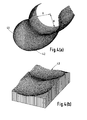
- Figure 4(a) is a perspective view similar to Figure 3(a) of a further embodiment in accordance with the invention and Figure 4(b) shows a perspective view of a corresponding tibial component,
- Figures 5(a), (b) & (c) show, diagrammatically, sagittal views of a prosthesis in accordance with the invention (Figures 5(b) & (c)) compared with a conventional design (Figure 5(a)),
- Figure 5(d) is a sagittal view of the profile of a patella replacement (in broken lines) compared with a conventional replacement (full lines),
- Figure 6 is an underside view of a femoral component showing the conformity of the patella with the patella groove,
- Figure 7(a) is a plan view of a tibial component in accordance with the invention,
- Figure 7(b) is a section taken on the line B-B in Figure 7(a),
- Figure 7(c) is a section taken on the line A-A in Figure 7(a),
- Figure 8(a) is a plan view of a modified tibial component,
- Figure 8(b) is a section taken on the line A-A in Figure 8(a) but with the anchoring pegs omitted,
- Figure 9(a) is a plan view of a further embodiment of tibial component and Figure 9(b) is a view taken on the line A-A in Figure 9(a), and
- Figure 10 is a view similar to Figures 7(b), 8(b) and 9b) of a modified tibial component showing alternative ways of guiding the plastics component.
- Figure 1 of the accompanying drawings shows a sagittal view of the natural knee at different flexion angles - 0 to 120° in thirty degree steps. The distal end 1 of the femur 2 can be seen to have a larger radius than the posterior 3. At zero degrees flexion, the larger radius distal end 1 contacts the top of the tibia 4, resulting in greater conformity and a greater area of contact. Other structures increase the contact area, notably the menisci, which are deformable discs interposed between the femoral and tibial condyles. When the knee is flexed, the femoral-tibial conformity is reduced, which would reduce the contact area and result in high contact stresses. However, the deformable menisci take up the shape between the femoral and tibial surface and once again spread the load. if the menisci are removed for injury, in later years, there is an increased chance of osteroarthritis.
- The knee displays both laxity (which can be termed freedom of motion) and stability, which is the control of displacements and rotations to within acceptable limits. Laxity can include linear or rotational translation in any of the three mutually perpendicular coordinate axes. For purposes of the invention, laxity is only considered in anterior-posterior displacement, medial-lateral displacement and internal-external rotation, these being the most significant. The anterior-posterior stability is provided mainly by the cruciate ligaments. The
anterior cruciate 5 can be seen in Figure 1, especially at the higher flexion angles. Rotational stability is provided by a combination of the cruciate and collateral ligaments. The muscles also play an important role in providing stability. The joint surfaces contribute to stability as force is applied across the joint, due to the slight dishing of the surfaces and the deformability of the articular cartilage. The laxity is due to the elastic extensibility of the ligaments, the joint surfaces, and other soft tissues surrounding the joint. - The patella is an important bone which transmits the force between the quadriceps and the upper tibia. In broad terms it can be regarded as a pulley, sliding up and down on the front of the femur. The patella fits closely into a groove on the front of the femur, such that the contact areas are broad bands across the width of the patella. Beyond about 90 degrees of flexion, the contact splits into two parts as the patella straddles the intercondylar groove.
- When a condylar replacement is introduced (Figure 2), a
femoral component 20 is attached to the end of the femur and atibial component 21 to the upper part of the tibia. Normally, the ends of the femoral condyles are resected and shaped to receive the femoral component and held in place with bone cement and/or pegs extending into the condyles. The collateral and cruciate ligaments can be preserved by providing aslot 22 in the femoral component, although in most designs, either the anterior is resected, or both cruciates are resected. Thepatella 23, either the natural patella or a replacement, fits into thegroove 24. When the knee is flexed with conventional prostheses, there is now a distinct lack of conformity between the femoral and tibial surfaces, with the result that the contact stresses on the plastic surface are high, leading to failure due to breakdown of the plastic in many cases. - Prior designs suffer from a number of problems; for example there is no meniscus to spread the force as in the normal knee. If the anterior cruciate is resected, there should ideally be a posterior upsweep of the tibial plastic surface to compensate, and if the posterior cruciate is resected also, an anterior upsweep is needed. in angles of flexion beyond about 90 degrees, there are two separate contacts on the patella component, leading to high stresses and deformation, and also sometimes 'catching'.
- A typical femoral component in accordance with the invention is shown in Figure 3(a). The condylar surfaces 31 resemble the anatomical, especially in the sagittal view, and there is a cut-out or slot 32 for one or both cruciate ligaments. A
patella groove 33 is continuous down to the cut-out 32 after which it splits. The larger femoral component in Figure 3(b) now has continuous surfaces throughout, including the patella groove, but is otherwise the same. Such a configuration requires resection of both cruciate ligaments. The femoral shape is then used to computer-generate atibial surface 35, based on input laxity requirements in anterior-posterior displacement and internal-external rotation. A computerised method of generating tibial surfaces is described in US Patent No. 4822365. The new femoral shape has two advantages. First, the contact on the tibial surface can now be spread over the entire width of the tibial surface, thus increasing the contact area. Second, the patella has a continuous track, and can maintain a broad contact area throughout motion, without a split of the contacts at higher flexion. However, there is still the disadvantage that the radius of curvature of the distal femur is greater than the posterior, such that once flexion is initiated, the smaller femoral radius contacts the tibia giving a reduction in contact area. - Figures 4(a) and 4(b) shows one solution to this problem. Here, the radius of the
posterior portion 41 of the femoral component has been carried round to thedistal femur 42. Now there is a constant radius R for contacting thetibial surface 43. A surface computer-generated with this component is clearly more dished than the previous component and provides an increase in the contact area throughout. The reduction in the contact stresses are calculated to be significant. Another benefit of the new surfaces is the enhanced stability. In the surfaces of Figure 3, it can be imagined that the flexed femur can slide forwards on the tibia with relatively little resistance. However, in Figure 4, the anterior sliding is much more restricted because of the steeper slope of the anterior tibial surface. - Certain characteristics of this design form are illustrated in Figure 5 which shows sagittal views of a standard design (Figure 5(a)) and a design in accordance with the invention, (Figures 5(b) and 5(c)). The differences in the distal femoral radii can be clearly seen. This change in distal radius has three consequences. More resection of anterior bone is needed for installation, although this is not a serious problem. The second problem is that the patella mechanics are altered. An important parameter of patella function is the lever arm, because this helps to determine quadriceps efficiency. With the knee at zero flexion, the lever arms are similar, but in mid-flexion (around 45 degrees), it can be appreciated that the lever arm of the design on the right will be reduced. This may not be a serious problem, but a possible remedy is to treat the bearing surfaces and patella surfaces as separate. The patella surface would then protrude as normal, in between the bearing surfaces. Such a solution reduces the width of the main bearing areas and may not represent an overall advantage. A final characteristic is that the femoral-tibial contact point is more posterior than normal. This has the advantage of improved quadriceps efficiency, as noted, but may result in upwards tilting of the front of the tibial component. If necessary, the position of the bottom of the curvature on the tibial surface could be moved anteriorly by 2-3mm which would alleviate this problem.
- An improvement to the patello-femoral contact is apparent from Figure 5. The normal dome-shape (Figure 5(a)) has high conformity when seen in the overhead view (Figure 6), but low conformity in the sagittal view. Several experimental and theoretical studies has shown that the angle through which the patella rotates relative to the femoral component in the sagittal plane is within 10 degrees (Figure 5(b) and 5(c)). This means that a high degree of conformity can be desired into the patella with no loss in freedom of motion. The new sagittal profile of the patella is shown dotted in figure 5(d). As can be seen, instead of having a continuous convex shape in sagittal view, it has a flattened
inner face 51 and outwardly extending surfaces 52 (Figure 6), giving greater conformity with the sides of thepatella groove 53. Such increase in conformity leads to greatly reduced contact stresses. A consequence of such a design is that if surgical placement is rotationally incorrect, there would be restriction of motion. However, the curvatures can be adjusted to allow for an appropriate margin of error. - The above design form in accordance with the invention is most suitable when the anterior and posterior cruciate ligaments are resected. In this case, there will still be sufficient anterior-posterior laxity (approximately 5 mm total) and rotational laxity (+ - 12 degrees), without restriction from taut ligaments. Such laxity will also be sufficient for activities of everyday living. The disadvantage is that the components are relied upon for stability, and in the long run, this may lead to problems with the fixation of the components to the bone. In addition, resection of the cruciates is believed to reduce the proprioceptive response of the knee with consequent compensatory gait patterns. A further disadvantage is that extremes of motion which occur during more demanding activities may be restricted, a possible disadvantage to younger or active patients. One approach to this problem is to use a meniscal bearing type of arrangement, already embodied in several designs, notably the LCS New Jersey, the Oxford, the Minns, and the Polyzoides - see US Patents Nos. 4340978 and 4085466. In these designs, anterior-posterior translation and internal-external rotation is completely unrestricted, except by impingement of the plastic bearing pieces onto capsular soft tissue at the anterior and posterior of the tracks. An important restriction to the designs however is that both the anterior and posterior cruciate ligaments are required, otherwise the stability is insufficient and the plastic bearings can dislocate.
- At least two of the designers of the above-named devices have considered the distal-posterior radius problem of the femoral component. If the radii were different, as in Figure 3, then the main advantage of the meniscal bearing concept, complete contact and low stresses, would be lost. US Patent No. 4,340,978 shows the meniscal bearing concept. In Figures 1 and 3 of this US Patent, the Oxford scheme is shown in US Patent No. 4,085,466. A uni-condylar femoral component has a spherical radius, but does not carry up into a patella flange. The New Jersey design opts for smaller radii posteriorly than distally (Figure 22), and illustrates the loss of full conformity in flexion in Figure 33.
- One further improvement provided by the present invention is to provide for sufficient anterior-posterior and rotational stability so that the prosthesis can be used with or without the cruciate ligaments, and to provide complete femoral-tibial conformity throughout the entire range of flexion. In essence, it consists of making the polished metal platform for supporting the plastic bearing piece or pieces concave when seen in the sagittal view. The effect will be to offer steadily increasing resistance to displacement away from the neutral position. In this respect, the stability and laxity characteristics can be made similar to that of a normal knee, or to a usual type of condylar prosthesis. The schematic views (Figure 7(a) shows the overall arrangement seen in plan view, with a metal plate or
platform 71, for attachment to the tibia, having a polished cylindrical surface on the top of the plate and aplastic bearing component 72 which slides on the polished surface. The femoral condylar surfaces are intended to have a constant sagittal radius in the region which articulates against the plastic surface, and conform closely with the tibial surface in both frontal and sagittal planes. An important feature is that the radius of the plastic surface is smaller than that of the cylindrical surface. The cylindrical shape of the bearing surfaces is shown in Figure 7(b) in which R² is greater than R². Figure 7(c) shows the medial-lateral section and acentral fixation peg 73 and anti-rotation pegs 74 to prevent theplatform 71 rotating on the tibia. - For a one-piece plastic component of the kind shown in Figures 7(a) - 7(c), rotation is not possible without loss of complete contact on the cylindrical surfaces. However, anterior-posterior displacement is possible. The arrangement providing anterior-posterior motion from a one-piece plastics tibial bearing component is shown in Figures 8(a) and 8(b) The
metal platform 81 supports aplastics bearing component 81 which is guided for anterior-posterior motion on arail 83 fixed or integral with theplatform 81. The platform may be curved in the sagittal plane as shown in Figure 7(b) or be planar. It may be convenient to constrain anterior-posterior motion within limits by providing suitable stops, e.g by means of anupstanding post 84 secured to the platform and anelongated hole 85 in thebearing pad 82. Thus, thepad 82 may move freely in an anterior-posterior direction into thepost 84 abutting one of the ends of the elongated hole. An alternative method of providing stops is indicated in dotted lines in Figure 8(a) in which the recess in theplastics meniscus component 82 has awall 86 against which the end face of therail 83 abuts to limit the anterior-posterior movement in one direction. -
Separate plastics pads 91,92 (see Figures 9(a) and 9(b)) are an alternative arrangement supported on acommon metal platform 93. Linear guidance is achieved by ametal rail 94, leaving a small clearance between the pads and the rail. Again, the bearing surface between the platform and the pads may be curved or planar. For two separate plastic components, both anterior-posterior translation and internal-external rotation are possible. For the latter, for bearing surfaces spaced apart 48 mm, only 0.8 mm inwards motion per side is needed to accommodate up to about + - 15 degrees of rotation. - Different ways can be envisaged to engage the plastic components, such as by T-shaped metal rails, under which a plastic lip is captured. This is illustrated in Figure 10, which is a view similar to Figure 7(c). A
tibial bearing pad 101 is supported for sliding anterior-posterior motion onplatform 103 Thepad 101 is trapped and guided byrail 102 having a 'T'-shaped profile section Figure 10 also shows an alternative trapping and guidance means bylateral guides 104 having inwardly turned projections 105 which engage in slots in the plastics pad. A central guide rail is preferred since this is less prone to jamming. - in the construction described above the femoral components and tibial metal platform are made from a metal acceptable for use for implantation in the human body. Examples are cobalt-chromium and titanium alloys and stainless steels. The artificial patella (where present) and/or the plastics bearing components may be made from any biocompatible material capable of withstanding the imposed loads and providing appropriate bearing properties when in contact with a polished metal surface. Preferably, the plastics material should exhibit low friction properties under these conditions. Examples of suitable materials are ultra-high molecular weight polyethylene or acetal copolymers.
Claims (12)
- A knee prosthesis which comprises a femoral component having a bearing surface whose radius in each sagittal section is substantially constant from posterior to a point more anterior than the distalmost point, and a tibial component having a concave bearing surface for supporting the femoral component, the bearing surfaces in the respective sagittal sections of the femoral and tibial components being substantially continuous from posterior to anterior, whereby contact between the femoral and tibial surfaces can be maintained across a substantial width of the joint throughout the range of flexion.
- A prosthesis according to claim 1 wherein the frontal plane sections of the femoral component are shaped to provide a patella groove whose shape corresponds to that of the anatomical or artificial patella, whereby the patella slides in substantial conformity with the patella groove through flexion between 0 and 90°.
- A prosthesis according to claim 1 or 2 wherein the tibial bearing surface comprises a plastics component which is mounted on a metal platform, the mating surface between the plastics component and the metal platform being substantially cylindrical with the axis of the cylinder extending in a lateral-medial line and the radius of the cylinder being at least as large as that of the sagittal radius of the femoral and tibial bearing surfaces.
- A prosthesis according to claim 3 wherein the motion of the tibial plastics component relative to the metal platform is constrained to an anterior-posterior direction by guide means.
- A prosthesis according to claim 4 wherein the guide means comprise a ridge formed in the metal plate extending in the anterior-posterior direction.
- A prosthesis according to claim 3 which includes two tibial plastics bearing components mounted on said metal platform, the mating surface between each plastics component and the metal platform being substantially cylindrical with the axis of the cylinder extending in a lateral-medial line.
- A prosthesis according to claim 6 wherein the plastics components are located on opposite sides of a guide rail extending in an anterior-posterior direction and serving to guide said plastics components for sliding movement relative to the metal platform in an anterior-posterior direction.
- A prosthesis according to claim 7 wherein a small clearance is provided between said plastics components and the guide rail, the arrangement being such as to permit limited freedom of anterior-posterior translation and internal-external rotation.
- A prosthesis according to claim 1 wherein the tibial bearing surface comprises a plastics component which is mounted on a metal platform for limited sliding motion in an anterior-posterior direction thereon and which includes guide means for constraining movement of the plastics component essentially in said anterior-posterior direction.
- A prosthesis according to claim 9 wherein said guide means comprises a rail member attached to the metal platform and extending in the anterior-posterior direction.
- A prosthesis according to claim 10 wherein the guide means includes stops limiting the extent of sliding motion of said plastics component in an anterior or posterior direction.
- A tibial component of a knee prosthesis which comprises a metal platform adapted to be secured to a resected tibia and a plastics bearing component mounted for sliding movement thereon, the mating surface between the plastics component and the metal platform being substantially cylindrical with the axis of the cylinder extending in a lateral-medial line and the radius of the cylinder being larger than the maximum sagittal radius of the femoral bearing surface.
Priority Applications (1)
| Application Number | Priority Date | Filing Date | Title |
|---|---|---|---|
| EP94112332A EP0626156B1 (en) | 1991-02-04 | 1992-01-31 | Prosthesis for knee replacement |
Applications Claiming Priority (2)
| Application Number | Priority Date | Filing Date | Title |
|---|---|---|---|
| GB9102348 | 1991-02-04 | ||
| GB919102348A GB9102348D0 (en) | 1991-02-04 | 1991-02-04 | Prosthesis for knee replacement |
Related Child Applications (1)
| Application Number | Title | Priority Date | Filing Date |
|---|---|---|---|
| EP94112332.5 Division-Into | 1992-01-31 |
Publications (2)
| Publication Number | Publication Date |
|---|---|
| EP0498586A1 true EP0498586A1 (en) | 1992-08-12 |
| EP0498586B1 EP0498586B1 (en) | 1997-01-08 |
Family
ID=10689495
Family Applications (2)
| Application Number | Title | Priority Date | Filing Date |
|---|---|---|---|
| EP92300878A Expired - Lifetime EP0498586B1 (en) | 1991-02-04 | 1992-01-31 | Prosthesis for knee replacement |
| EP94112332A Expired - Lifetime EP0626156B1 (en) | 1991-02-04 | 1992-01-31 | Prosthesis for knee replacement |
Family Applications After (1)
| Application Number | Title | Priority Date | Filing Date |
|---|---|---|---|
| EP94112332A Expired - Lifetime EP0626156B1 (en) | 1991-02-04 | 1992-01-31 | Prosthesis for knee replacement |
Country Status (6)
| Country | Link |
|---|---|
| US (1) | US5330533A (en) |
| EP (2) | EP0498586B1 (en) |
| AT (2) | ATE147252T1 (en) |
| DE (2) | DE69216437T2 (en) |
| ES (2) | ES2105441T3 (en) |
| GB (1) | GB9102348D0 (en) |
Cited By (30)
| Publication number | Priority date | Publication date | Assignee | Title |
|---|---|---|---|---|
| EP0546726A1 (en) * | 1991-11-28 | 1993-06-16 | Biomet Limited | Prosthetic knee joint |
| WO1993011720A1 (en) * | 1991-12-11 | 1993-06-24 | Theusner, Joachim | Artificial joint |
| FR2699399A1 (en) * | 1992-12-17 | 1994-06-24 | Luer Sa | Artificial knee prosthesis |
| US5326358A (en) * | 1991-08-28 | 1994-07-05 | Sulzer Medizinaltechnik Ag | Knee joint prosthesis |
| DE4310968A1 (en) * | 1993-04-03 | 1994-10-06 | Kubein Meesenburg Dietmar | Artificial joint to replace the human kneecap |
| US5358530A (en) * | 1993-03-29 | 1994-10-25 | Zimmer, Inc. | Mobile bearing knee |
| WO1994026212A1 (en) * | 1993-05-18 | 1994-11-24 | Walker Peter S | Knee prosthesis with femoral, tibial conformity |
| GB2280375A (en) * | 1993-07-16 | 1995-02-01 | Walker Peter S | Prosthesis for knee replacement |
| EP0634156A3 (en) * | 1993-07-16 | 1995-04-12 | Walker Peter S | Prosthesis for knee replacement. |
| WO1995014444A1 (en) * | 1993-11-23 | 1995-06-01 | Plus Endoprothetik Ag | System for constructing a knee-joint endoprosthesis |
| WO1995017860A1 (en) * | 1993-12-30 | 1995-07-06 | Plus Endoprothetik Ag | Knee endoprosthesis |
| FR2714819A1 (en) * | 1994-01-10 | 1995-07-13 | Billy Jean Louis | Knee joint replacement prosthesis components |
| FR2726174A1 (en) * | 1994-10-26 | 1996-05-03 | Cornic Michel | KNEE JOINT PROSTHESIS |
| WO1997000053A1 (en) * | 1995-06-14 | 1997-01-03 | Theusner, Joachim | Artificial joint, in particular endoprosthesis for replacing natural joints |
| US5609639A (en) * | 1991-02-04 | 1997-03-11 | Walker; Peter S. | Prosthesis for knee replacement |
| US5871541A (en) * | 1993-11-23 | 1999-02-16 | Plus Endoprothetik, Ag | System for producing a knee-joint endoprosthesis |
| DE19823325C1 (en) * | 1998-05-26 | 2000-03-23 | Werner Scholz | Prosthetic system for knee joint |
| US6123728A (en) * | 1997-09-17 | 2000-09-26 | Smith & Nephew, Inc. | Mobile bearing knee prosthesis |
| US6210445B1 (en) | 1999-10-26 | 2001-04-03 | Bristol-Myers Squibb Company | Tibial knee component with a mobile bearing |
| US6210444B1 (en) | 1999-10-26 | 2001-04-03 | Bristol-Myers Squibb Company | Tibial knee component with a mobile bearing |
| US6217618B1 (en) | 1999-10-26 | 2001-04-17 | Bristol-Myers Squibb Company | Tibial knee component with a mobile bearing |
| US6319283B1 (en) | 1999-07-02 | 2001-11-20 | Bristol-Myers Squibb Company | Tibial knee component with a mobile bearing |
| US6428577B1 (en) | 1998-05-20 | 2002-08-06 | Smith & Nephew, Inc. | Mobile bearing knee prosthesis |
| US6660039B1 (en) | 1998-05-20 | 2003-12-09 | Smith & Nephew, Inc. | Mobile bearing knee prosthesis |
| US6972039B2 (en) | 1999-03-01 | 2005-12-06 | Biomet, Inc. | Floating bearing knee joint prosthesis with a fixed tibial post |
| EP1525862A3 (en) * | 2003-10-21 | 2005-12-28 | Königsee Implantate und Instrumente zur Ostheosynthese GmbH | Tibial baseplate for a knee endoprothesis. |
| DE102004037877A1 (en) * | 2004-08-04 | 2006-02-23 | Fraunhofer-Gesellschaft zur Förderung der angewandten Forschung e.V. | Prosthetic device, in particular foot prosthesis |
| US7422605B2 (en) | 2003-07-17 | 2008-09-09 | Exactech, Inc. | Mobile bearing knee prosthesis |
| US7708782B2 (en) | 2003-07-17 | 2010-05-04 | Exactech, Inc. | Mobile bearing knee prosthesis |
| US8308808B2 (en) | 2010-02-19 | 2012-11-13 | Biomet Manufacturing Corp. | Latent mobile bearing for prosthetic device |
Families Citing this family (111)
| Publication number | Priority date | Publication date | Assignee | Title |
|---|---|---|---|---|
| US8603095B2 (en) | 1994-09-02 | 2013-12-10 | Puget Bio Ventures LLC | Apparatuses for femoral and tibial resection |
| US6695848B2 (en) | 1994-09-02 | 2004-02-24 | Hudson Surgical Design, Inc. | Methods for femoral and tibial resection |
| US5683468A (en) * | 1995-03-13 | 1997-11-04 | Pappas; Michael J. | Mobile bearing total joint replacement |
| US5702465A (en) * | 1996-05-13 | 1997-12-30 | Sulzer Orthopedics Inc. | Patella prosthesis having rotational and translational freedom |
| US5824100A (en) * | 1996-10-30 | 1998-10-20 | Osteonics Corp. | Knee prosthesis with increased balance and reduced bearing stress |
| US7618451B2 (en) | 2001-05-25 | 2009-11-17 | Conformis, Inc. | Patient selectable joint arthroplasty devices and surgical tools facilitating increased accuracy, speed and simplicity in performing total and partial joint arthroplasty |
| US8882847B2 (en) | 2001-05-25 | 2014-11-11 | Conformis, Inc. | Patient selectable knee joint arthroplasty devices |
| US8771365B2 (en) | 2009-02-25 | 2014-07-08 | Conformis, Inc. | Patient-adapted and improved orthopedic implants, designs, and related tools |
| US9603711B2 (en) | 2001-05-25 | 2017-03-28 | Conformis, Inc. | Patient-adapted and improved articular implants, designs and related guide tools |
| US8545569B2 (en) | 2001-05-25 | 2013-10-01 | Conformis, Inc. | Patient selectable knee arthroplasty devices |
| US8083745B2 (en) | 2001-05-25 | 2011-12-27 | Conformis, Inc. | Surgical tools for arthroplasty |
| US8556983B2 (en) | 2001-05-25 | 2013-10-15 | Conformis, Inc. | Patient-adapted and improved orthopedic implants, designs and related tools |
| US8735773B2 (en) | 2007-02-14 | 2014-05-27 | Conformis, Inc. | Implant device and method for manufacture |
| US7534263B2 (en) | 2001-05-25 | 2009-05-19 | Conformis, Inc. | Surgical tools facilitating increased accuracy, speed and simplicity in performing joint arthroplasty |
| US8480754B2 (en) | 2001-05-25 | 2013-07-09 | Conformis, Inc. | Patient-adapted and improved articular implants, designs and related guide tools |
| US7468075B2 (en) | 2001-05-25 | 2008-12-23 | Conformis, Inc. | Methods and compositions for articular repair |
| US6039764A (en) * | 1997-08-18 | 2000-03-21 | Arch Development Corporation | Prosthetic knee with adjusted center of internal/external rotation |
| US5951603A (en) * | 1997-09-25 | 1999-09-14 | Johnson & Johnson Professional, Inc. | Rotatable joint prosthesis with axial securement |
| US6010534A (en) * | 1997-09-25 | 2000-01-04 | Johnson & Johnson Professional, Inc. | Rotatable tibial prosthesis with keyed axial securement |
| US6053945A (en) * | 1997-09-25 | 2000-04-25 | Johnson & Johnson Professional, Inc. | Joint prosthesis having controlled rotation |
| US5957979A (en) * | 1997-12-12 | 1999-09-28 | Bristol-Myers Squibb Company | Mobile bearing knee with metal on metal interface |
| US6162253A (en) * | 1997-12-31 | 2000-12-19 | Iowa State University Research Foundation, Inc. | Total elbow arthroplasty system |
| CA2354525A1 (en) | 1998-09-14 | 2000-06-22 | Stanford University | Assessing the condition of a joint and preventing damage |
| US7239908B1 (en) | 1998-09-14 | 2007-07-03 | The Board Of Trustees Of The Leland Stanford Junior University | Assessing the condition of a joint and devising treatment |
| US6306171B1 (en) | 1998-12-09 | 2001-10-23 | Iowa State University Research Foundation, Inc. | Total elbow arthroplasty system |
| US6165223A (en) * | 1999-03-01 | 2000-12-26 | Biomet, Inc. | Floating bearing knee joint prosthesis with a fixed tibial post |
| US6413279B1 (en) | 1999-03-01 | 2002-07-02 | Biomet, Inc. | Floating bearing knee joint prosthesis with a fixed tibial post |
| US8066776B2 (en) * | 2001-12-14 | 2011-11-29 | Btg International Limited | Tibial component |
| FR2796836B1 (en) * | 1999-07-26 | 2002-03-22 | Michel Bercovy | NEW KNEE PROSTHESIS |
| WO2001080772A1 (en) * | 2000-04-21 | 2001-11-01 | Behrooz Tohidi | Wear-resistant artificial joint |
| EP1322224B1 (en) | 2000-09-14 | 2008-11-05 | The Board Of Trustees Of The Leland Stanford Junior University | Assessing condition of a joint and cartilage loss |
| ATE426357T1 (en) | 2000-09-14 | 2009-04-15 | Univ Leland Stanford Junior | ASSESSING THE CONDITION OF A JOINT AND PLANNING TREATMENT |
| US6558426B1 (en) | 2000-11-28 | 2003-05-06 | Medidea, Llc | Multiple-cam, posterior-stabilized knee prosthesis |
| US8062377B2 (en) | 2001-03-05 | 2011-11-22 | Hudson Surgical Design, Inc. | Methods and apparatus for knee arthroplasty |
| US7695521B2 (en) | 2001-05-01 | 2010-04-13 | Amedica Corporation | Hip prosthesis with monoblock ceramic acetabular cup |
| US7776085B2 (en) * | 2001-05-01 | 2010-08-17 | Amedica Corporation | Knee prosthesis with ceramic tibial component |
| US6770077B2 (en) | 2001-05-21 | 2004-08-03 | Nemco Medical, Ltd. | Femoral knee saw guide and method |
| US8439926B2 (en) | 2001-05-25 | 2013-05-14 | Conformis, Inc. | Patient selectable joint arthroplasty devices and surgical tools |
| EP1389980B1 (en) | 2001-05-25 | 2011-04-06 | Conformis, Inc. | Methods and compositions for articular resurfacing |
| EP1408874B1 (en) * | 2001-06-14 | 2012-08-08 | Amedica Corporation | Metal-ceramic composite articulation |
| CA2475142C (en) * | 2002-02-26 | 2009-04-28 | Donald M. Smucker | Patella resection guide |
| CA2474967C (en) * | 2002-03-05 | 2009-09-29 | Nemcomed, Inc. | Minimally invasive total knee arthroplasty method and instrumentation |
| DE10225217A1 (en) * | 2002-06-06 | 2003-12-18 | Klaus Draenert | Arrangement for partly replacing surfaces and bone under stress involves cylindrical basic body implant |
| ATE497740T1 (en) | 2002-10-07 | 2011-02-15 | Conformis Inc | MINIMALLY INVASIVE JOINT IMPLANT WITH A THREE-DIMENSIONAL GEOMETRY ADAPTED TO THE JOINT SURFACES |
| CN1780594A (en) | 2002-11-07 | 2006-05-31 | 康复米斯公司 | Methods for determining meniscal size and shape and for devising treatment |
| AU2003297195A1 (en) * | 2002-12-17 | 2004-07-22 | Amedica Corporation | Total disc implant |
| JP4943655B2 (en) | 2002-12-20 | 2012-05-30 | スミス アンド ネフュー インコーポレーテッド | High performance knee prosthesis |
| US20040153066A1 (en) * | 2003-02-03 | 2004-08-05 | Coon Thomas M. | Apparatus for knee surgery and method of use |
| US20050143832A1 (en) | 2003-10-17 | 2005-06-30 | Carson Christopher P. | High flexion articular insert |
| DE10361780B4 (en) * | 2003-10-21 | 2008-11-13 | Königsee Implantate und Instrumente zur Osteosynthese GmbH | Tibial plateau component for a knee endoprosthesis |
| US8021368B2 (en) | 2004-01-14 | 2011-09-20 | Hudson Surgical Design, Inc. | Methods and apparatus for improved cutting tools for resection |
| US20060030854A1 (en) | 2004-02-02 | 2006-02-09 | Haines Timothy G | Methods and apparatus for wireplasty bone resection |
| US8114083B2 (en) | 2004-01-14 | 2012-02-14 | Hudson Surgical Design, Inc. | Methods and apparatus for improved drilling and milling tools for resection |
| US20060030855A1 (en) | 2004-03-08 | 2006-02-09 | Haines Timothy G | Methods and apparatus for improved profile based resection |
| US7435448B2 (en) * | 2004-02-06 | 2008-10-14 | Hewlett-Packard Development Company, L.P. | Sulfur-containing inorganic media coatings for ink-jet applications |
| US8292964B2 (en) * | 2005-12-14 | 2012-10-23 | New York University | Surface guided knee replacement |
| US8211181B2 (en) * | 2005-12-14 | 2012-07-03 | New York University | Surface guided knee replacement |
| GB0526385D0 (en) * | 2005-12-28 | 2006-02-08 | Mcminn Derek J W | Improvements in or relating to knee prosthesis |
| US8623026B2 (en) | 2006-02-06 | 2014-01-07 | Conformis, Inc. | Patient selectable joint arthroplasty devices and surgical tools incorporating anatomical relief |
| CN102599960B (en) | 2006-02-06 | 2015-08-12 | 康复米斯公司 | The arthroplasty devices that patient-selectable selects and surgical instrument |
| EP1996122B1 (en) | 2006-03-21 | 2012-11-21 | DePuy (Ireland) | Moment induced total arthroplasty prosthetic |
| CN101484094B (en) | 2006-06-30 | 2013-01-02 | 史密夫和内修有限公司 | anatomical movement articulated prosthesis |
| US20080097450A1 (en) * | 2006-09-14 | 2008-04-24 | Zimmer Technology, Inc. | Patella clamp |
| WO2008101090A2 (en) | 2007-02-14 | 2008-08-21 | Conformis, Inc. | Implant device and method for manufacture |
| WO2008157412A2 (en) | 2007-06-13 | 2008-12-24 | Conformis, Inc. | Surgical cutting guide |
| DE102007056141B4 (en) | 2007-11-19 | 2020-04-23 | Ohst Medizintechnik Ag | Tibia insert |
| US8292965B2 (en) * | 2008-02-11 | 2012-10-23 | New York University | Knee joint with a ramp |
| US8682052B2 (en) | 2008-03-05 | 2014-03-25 | Conformis, Inc. | Implants for altering wear patterns of articular surfaces |
| AU2009246474B2 (en) | 2008-05-12 | 2015-04-16 | Conformis, Inc. | Devices and methods for treatment of facet and other joints |
| EP2323594B1 (en) * | 2008-06-24 | 2016-04-06 | Peter Stanley Walker | Recess-ramp knee joint prosthesis |
| US8206451B2 (en) | 2008-06-30 | 2012-06-26 | Depuy Products, Inc. | Posterior stabilized orthopaedic prosthesis |
| US8236061B2 (en) | 2008-06-30 | 2012-08-07 | Depuy Products, Inc. | Orthopaedic knee prosthesis having controlled condylar curvature |
| US9119723B2 (en) | 2008-06-30 | 2015-09-01 | Depuy (Ireland) | Posterior stabilized orthopaedic prosthesis assembly |
| US8187335B2 (en) | 2008-06-30 | 2012-05-29 | Depuy Products, Inc. | Posterior stabilized orthopaedic knee prosthesis having controlled condylar curvature |
| US9168145B2 (en) | 2008-06-30 | 2015-10-27 | Depuy (Ireland) | Posterior stabilized orthopaedic knee prosthesis having controlled condylar curvature |
| US8828086B2 (en) * | 2008-06-30 | 2014-09-09 | Depuy (Ireland) | Orthopaedic femoral component having controlled condylar curvature |
| US8192498B2 (en) | 2008-06-30 | 2012-06-05 | Depuy Products, Inc. | Posterior cructiate-retaining orthopaedic knee prosthesis having controlled condylar curvature |
| US8202323B2 (en) * | 2008-07-16 | 2012-06-19 | Depuy Products, Inc. | Knee prostheses with enhanced kinematics |
| US7981159B2 (en) * | 2008-07-16 | 2011-07-19 | Depuy Products, Inc. | Antero-posterior placement of axis of rotation for a rotating platform |
| US8808297B2 (en) | 2009-02-24 | 2014-08-19 | Microport Orthopedics Holdings Inc. | Orthopedic surgical guide |
| US12383287B2 (en) | 2009-02-24 | 2025-08-12 | Microport Orthopedics Holdings, Inc. | Systems and methods for installing an orthopedic implant |
| US9017334B2 (en) | 2009-02-24 | 2015-04-28 | Microport Orthopedics Holdings Inc. | Patient specific surgical guide locator and mount |
| EP2405865B1 (en) | 2009-02-24 | 2019-04-17 | ConforMIS, Inc. | Automated systems for manufacturing patient-specific orthopedic implants and instrumentation |
| US8808303B2 (en) | 2009-02-24 | 2014-08-19 | Microport Orthopedics Holdings Inc. | Orthopedic surgical guide |
| CN102448394B (en) | 2009-04-16 | 2015-07-22 | 康复米斯公司 | Patient-specific joint arthroplasty devices for ligament repair |
| US8915965B2 (en) | 2009-05-07 | 2014-12-23 | Depuy (Ireland) | Anterior stabilized knee implant |
| EP2272466A1 (en) * | 2009-07-10 | 2011-01-12 | Medizinische Hochschule Hannover | Knee joint prosthesis and method for producing said prosthesis |
| US8568485B2 (en) * | 2009-08-11 | 2013-10-29 | Imds Corporation | Articulating trials for prosthetic implants |
| US9095453B2 (en) * | 2009-08-11 | 2015-08-04 | Michael D. Ries | Position adjustable trial systems for prosthetic implants |
| US8998997B2 (en) | 2009-08-11 | 2015-04-07 | Michael D. Ries | Implantable mobile bearing prosthetics |
| US8382848B2 (en) * | 2009-08-11 | 2013-02-26 | Imds Corporation | Position adjustable trial systems for prosthetic implants |
| US8496666B2 (en) | 2009-08-11 | 2013-07-30 | Imds Corporation | Instrumentation for mobile bearing prosthetics |
| US8906105B2 (en) | 2009-08-11 | 2014-12-09 | Michael D. Ries | Systems and methods for mobile bearing prosthetic knee |
| CA2782137A1 (en) | 2009-12-11 | 2011-06-16 | Conformis, Inc. | Patient-specific and patient-engineered orthopedic implants |
| TR201815901T4 (en) | 2010-01-29 | 2018-11-21 | Smith & Nephew Inc | Knee replacement supporting cross ligament. |
| WO2012012726A1 (en) | 2010-07-23 | 2012-01-26 | Medicinelodge, Inc Dba Imds Co-Innovation | Systems and methods for prosthetic knee |
| CA2808090C (en) | 2010-08-12 | 2018-09-11 | Smith & Nephew, Inc. | Structures for use in orthopaedic implant fixation and methods of installation onto a bone |
| US8747410B2 (en) | 2010-10-26 | 2014-06-10 | Zimmer, Inc. | Patellar resection instrument with variable depth guide |
| WO2012112694A2 (en) | 2011-02-15 | 2012-08-23 | Conformis, Inc. | Medeling, analyzing and using anatomical data for patient-adapted implants. designs, tools and surgical procedures |
| US8409293B1 (en) | 2011-10-26 | 2013-04-02 | Sevika Holding AG | Knee prosthesis |
| US8702803B2 (en) | 2011-12-29 | 2014-04-22 | Mako Surgical Corp. | Locking assembly for tibial prosthesis component |
| US9486226B2 (en) | 2012-04-18 | 2016-11-08 | Conformis, Inc. | Tibial guides, tools, and techniques for resecting the tibial plateau |
| US20130317523A1 (en) * | 2012-05-22 | 2013-11-28 | Todd Borus | Total Knee Arthroplasty Apparatus and Method of Use |
| US9675471B2 (en) | 2012-06-11 | 2017-06-13 | Conformis, Inc. | Devices, techniques and methods for assessing joint spacing, balancing soft tissues and obtaining desired kinematics for joint implant components |
| AU2014228237B2 (en) | 2013-03-15 | 2016-09-08 | Mako Surgical Corp. | Unicondylar tibial knee implant |
| US10179052B2 (en) | 2016-07-28 | 2019-01-15 | Depuy Ireland Unlimited Company | Total knee implant prosthesis assembly and method |
| WO2018102610A2 (en) | 2016-11-30 | 2018-06-07 | Rasmussen G Lynn | Systems and methods for providing a tibial baseplate |
| EP3412252B1 (en) | 2017-06-09 | 2020-02-12 | Howmedica Osteonics Corp. | Polymer interlock support structure |
| CA3129217A1 (en) | 2019-05-29 | 2020-12-03 | Wright Medical Technology, Inc. | Preparing a tibia for receiving tibial implant component of a replacement ankle |
| US12396739B2 (en) | 2020-01-17 | 2025-08-26 | Wright Medical Technology, Inc. | Guidance tools, systems, and methods |
| WO2022182430A1 (en) | 2021-02-24 | 2022-09-01 | Wright Medical Technology, Inc. | Preparing a tibia for receiving tibial implant component of a replacement ankle |
Citations (6)
| Publication number | Priority date | Publication date | Assignee | Title |
|---|---|---|---|---|
| US4085466A (en) * | 1974-11-18 | 1978-04-25 | National Research Development Corporation | Prosthetic joint device |
| US4224696A (en) * | 1978-09-08 | 1980-09-30 | Hexcel Corporation | Prosthetic knee |
| US4340978A (en) * | 1979-07-02 | 1982-07-27 | Biomedical Engineering Corp. | New Jersey meniscal bearing knee replacement |
| US4586933A (en) * | 1983-09-30 | 1986-05-06 | Hiromu Shoji | Dual articulating total knee prosthesis |
| EP0349173A1 (en) * | 1988-06-22 | 1990-01-03 | John Polyzoides | Knee prosthesis |
| EP0442330A2 (en) * | 1990-02-16 | 1991-08-21 | Friatec Aktiengesellschaft Keramik- und Kunststoffwerke | Kneejoint endroprosthesis |
Family Cites Families (13)
| Publication number | Priority date | Publication date | Assignee | Title |
|---|---|---|---|---|
| GB1509194A (en) * | 1974-04-22 | 1978-05-04 | Nat Res Dev | Endoprosthetic devices |
| US4215439A (en) * | 1978-10-16 | 1980-08-05 | Zimmer, USA | Semi-restraining knee prosthesis |
| DE3433264C2 (en) * | 1984-09-11 | 1986-10-02 | S + G Implants GmbH, 2400 Lübeck | Tibial part for a knee joint endoprosthesis |
| US4673407A (en) * | 1985-02-20 | 1987-06-16 | Martin Daniel L | Joint-replacement prosthetic device |
| DE3529894A1 (en) * | 1985-08-21 | 1987-03-05 | Orthoplant Endoprothetik | Knee-joint endoprosthesis |
| US4714474A (en) * | 1986-05-12 | 1987-12-22 | Dow Corning Wright Corporation | Tibial knee joint prosthesis with removable articulating surface insert |
| US4822365A (en) * | 1986-05-30 | 1989-04-18 | Walker Peter S | Method of design of human joint prosthesis |
| US4822362A (en) * | 1987-05-19 | 1989-04-18 | Walker Peter S | Process and apparatus for tibial plateau compenent |
| US5147405A (en) * | 1990-02-07 | 1992-09-15 | Boehringer Mannheim Corporation | Knee prosthesis |
| GB9005496D0 (en) * | 1990-03-12 | 1990-05-09 | Howmedica | Tibial component for a replacement knee prosthesis and total knee prosthesis incorporating such a component |
| US5116375A (en) * | 1990-08-27 | 1992-05-26 | Hofmann Aaron A | Knee prosthesis |
| GB9102633D0 (en) * | 1991-02-07 | 1991-03-27 | Finsbury Instr Ltd | Knee prosthesis |
| US5133758A (en) * | 1991-09-16 | 1992-07-28 | Research And Education Institute, Inc. Harbor-Ucla Medical Center | Total knee endoprosthesis with fixed flexion-extension axis of rotation |
-
1991
- 1991-02-04 GB GB919102348A patent/GB9102348D0/en active Pending
-
1992
- 1992-01-31 EP EP92300878A patent/EP0498586B1/en not_active Expired - Lifetime
- 1992-01-31 EP EP94112332A patent/EP0626156B1/en not_active Expired - Lifetime
- 1992-01-31 ES ES94112332T patent/ES2105441T3/en not_active Expired - Lifetime
- 1992-01-31 AT AT92300878T patent/ATE147252T1/en not_active IP Right Cessation
- 1992-01-31 DE DE69216437T patent/DE69216437T2/en not_active Expired - Lifetime
- 1992-01-31 AT AT94112332T patent/ATE155667T1/en not_active IP Right Cessation
- 1992-01-31 ES ES92300878T patent/ES2096024T3/en not_active Expired - Lifetime
- 1992-01-31 DE DE69221162T patent/DE69221162T2/en not_active Expired - Lifetime
- 1992-02-03 US US07/829,369 patent/US5330533A/en not_active Expired - Lifetime
Patent Citations (6)
| Publication number | Priority date | Publication date | Assignee | Title |
|---|---|---|---|---|
| US4085466A (en) * | 1974-11-18 | 1978-04-25 | National Research Development Corporation | Prosthetic joint device |
| US4224696A (en) * | 1978-09-08 | 1980-09-30 | Hexcel Corporation | Prosthetic knee |
| US4340978A (en) * | 1979-07-02 | 1982-07-27 | Biomedical Engineering Corp. | New Jersey meniscal bearing knee replacement |
| US4586933A (en) * | 1983-09-30 | 1986-05-06 | Hiromu Shoji | Dual articulating total knee prosthesis |
| EP0349173A1 (en) * | 1988-06-22 | 1990-01-03 | John Polyzoides | Knee prosthesis |
| EP0442330A2 (en) * | 1990-02-16 | 1991-08-21 | Friatec Aktiengesellschaft Keramik- und Kunststoffwerke | Kneejoint endroprosthesis |
Cited By (44)
| Publication number | Priority date | Publication date | Assignee | Title |
|---|---|---|---|---|
| US5609639A (en) * | 1991-02-04 | 1997-03-11 | Walker; Peter S. | Prosthesis for knee replacement |
| US5326358A (en) * | 1991-08-28 | 1994-07-05 | Sulzer Medizinaltechnik Ag | Knee joint prosthesis |
| EP0546726A1 (en) * | 1991-11-28 | 1993-06-16 | Biomet Limited | Prosthetic knee joint |
| WO1993011720A1 (en) * | 1991-12-11 | 1993-06-24 | Theusner, Joachim | Artificial joint |
| US5556432A (en) * | 1991-12-11 | 1996-09-17 | Joachim Theusner | Artificial joint |
| FR2699399A1 (en) * | 1992-12-17 | 1994-06-24 | Luer Sa | Artificial knee prosthesis |
| US5358530A (en) * | 1993-03-29 | 1994-10-25 | Zimmer, Inc. | Mobile bearing knee |
| US5738686A (en) * | 1993-04-03 | 1998-04-14 | Joachim Theusner | Artificial joint to replace the human patella |
| DE4310968A1 (en) * | 1993-04-03 | 1994-10-06 | Kubein Meesenburg Dietmar | Artificial joint to replace the human kneecap |
| WO1994026212A1 (en) * | 1993-05-18 | 1994-11-24 | Walker Peter S | Knee prosthesis with femoral, tibial conformity |
| AU685804B2 (en) * | 1993-05-18 | 1998-01-29 | John Nevil Insall | Knee prosthesis with femoral, tibial conformity |
| US5725584A (en) * | 1993-05-18 | 1998-03-10 | Walker; Peter Stanley | Knee prosthesis with femoral, tibial conformity |
| EP0634156A3 (en) * | 1993-07-16 | 1995-04-12 | Walker Peter S | Prosthesis for knee replacement. |
| EP0634155A3 (en) * | 1993-07-16 | 1995-04-12 | Walker Peter S | Prosthesis for knee replacement. |
| AU685459B2 (en) * | 1993-07-16 | 1998-01-22 | Peter Stanley Walker | Prosthesis for knee replacement |
| GB2280375A (en) * | 1993-07-16 | 1995-02-01 | Walker Peter S | Prosthesis for knee replacement |
| GB2280375B (en) * | 1993-07-16 | 1997-09-10 | Walker Peter S | Prosthesis for knee replacement |
| US5871541A (en) * | 1993-11-23 | 1999-02-16 | Plus Endoprothetik, Ag | System for producing a knee-joint endoprosthesis |
| WO1995014444A1 (en) * | 1993-11-23 | 1995-06-01 | Plus Endoprothetik Ag | System for constructing a knee-joint endoprosthesis |
| WO1995017860A1 (en) * | 1993-12-30 | 1995-07-06 | Plus Endoprothetik Ag | Knee endoprosthesis |
| US5755802A (en) * | 1993-12-30 | 1998-05-26 | Bruno E. Gerber | Knee-joint endoprosthesis |
| FR2714819A1 (en) * | 1994-01-10 | 1995-07-13 | Billy Jean Louis | Knee joint replacement prosthesis components |
| EP0670151A3 (en) * | 1994-01-10 | 1997-12-29 | Jean-Louis Billy | Knee prothesis |
| WO1996013232A1 (en) * | 1994-10-26 | 1996-05-09 | Aurex | Knee joint prosthesis |
| FR2726174A1 (en) * | 1994-10-26 | 1996-05-03 | Cornic Michel | KNEE JOINT PROSTHESIS |
| WO1997000053A1 (en) * | 1995-06-14 | 1997-01-03 | Theusner, Joachim | Artificial joint, in particular endoprosthesis for replacing natural joints |
| US6123728A (en) * | 1997-09-17 | 2000-09-26 | Smith & Nephew, Inc. | Mobile bearing knee prosthesis |
| US6428577B1 (en) | 1998-05-20 | 2002-08-06 | Smith & Nephew, Inc. | Mobile bearing knee prosthesis |
| US6660039B1 (en) | 1998-05-20 | 2003-12-09 | Smith & Nephew, Inc. | Mobile bearing knee prosthesis |
| DE19823325C1 (en) * | 1998-05-26 | 2000-03-23 | Werner Scholz | Prosthetic system for knee joint |
| US6972039B2 (en) | 1999-03-01 | 2005-12-06 | Biomet, Inc. | Floating bearing knee joint prosthesis with a fixed tibial post |
| US6319283B1 (en) | 1999-07-02 | 2001-11-20 | Bristol-Myers Squibb Company | Tibial knee component with a mobile bearing |
| US6217618B1 (en) | 1999-10-26 | 2001-04-17 | Bristol-Myers Squibb Company | Tibial knee component with a mobile bearing |
| US6210444B1 (en) | 1999-10-26 | 2001-04-03 | Bristol-Myers Squibb Company | Tibial knee component with a mobile bearing |
| US6210445B1 (en) | 1999-10-26 | 2001-04-03 | Bristol-Myers Squibb Company | Tibial knee component with a mobile bearing |
| US7708782B2 (en) | 2003-07-17 | 2010-05-04 | Exactech, Inc. | Mobile bearing knee prosthesis |
| US7422605B2 (en) | 2003-07-17 | 2008-09-09 | Exactech, Inc. | Mobile bearing knee prosthesis |
| EP1525862A3 (en) * | 2003-10-21 | 2005-12-28 | Königsee Implantate und Instrumente zur Ostheosynthese GmbH | Tibial baseplate for a knee endoprothesis. |
| DE102004037877A1 (en) * | 2004-08-04 | 2006-02-23 | Fraunhofer-Gesellschaft zur Förderung der angewandten Forschung e.V. | Prosthetic device, in particular foot prosthesis |
| DE102004037877B4 (en) * | 2004-08-04 | 2010-04-29 | Bauerfeind Ag | Foot prosthesis |
| US7862621B2 (en) | 2004-08-04 | 2011-01-04 | Fraunhofer-Gesellschaft Zur Forderung Der Angewandten Forschung E.V. | Prosthesis, in particular prosthetic foot |
| US8308808B2 (en) | 2010-02-19 | 2012-11-13 | Biomet Manufacturing Corp. | Latent mobile bearing for prosthetic device |
| US8986391B2 (en) | 2010-02-19 | 2015-03-24 | Biomet Manufacturing, Llc | Latent mobile bearing for prosthetic device |
| US9498341B2 (en) | 2010-02-19 | 2016-11-22 | Biomet Manufacturing, Llc | Latent mobile bearing for prosthetic device |
Also Published As
| Publication number | Publication date |
|---|---|
| EP0626156A2 (en) | 1994-11-30 |
| EP0626156B1 (en) | 1997-07-23 |
| GB9102348D0 (en) | 1991-03-20 |
| ATE155667T1 (en) | 1997-08-15 |
| ES2096024T3 (en) | 1997-03-01 |
| DE69221162D1 (en) | 1997-08-28 |
| DE69216437D1 (en) | 1997-02-20 |
| US5330533A (en) | 1994-07-19 |
| DE69216437T2 (en) | 1997-04-24 |
| EP0626156A3 (en) | 1994-12-28 |
| ATE147252T1 (en) | 1997-01-15 |
| EP0498586B1 (en) | 1997-01-08 |
| DE69221162T2 (en) | 1997-11-27 |
| ES2105441T3 (en) | 1997-10-16 |
Similar Documents
| Publication | Publication Date | Title |
|---|---|---|
| EP0626156B1 (en) | Prosthesis for knee replacement | |
| US5609639A (en) | Prosthesis for knee replacement | |
| EP0634155B1 (en) | Prosthesis for knee replacement | |
| US5011496A (en) | Prosthetic joint | |
| US4888021A (en) | Knee and patellar prosthesis | |
| US5723016A (en) | Implantable prosthetic patellar components | |
| US10383738B2 (en) | Tibial component | |
| EP0848602B1 (en) | Knee prosthesis | |
| US5997577A (en) | Knee joint prosthesis | |
| US5871545A (en) | Prosthetic knee joint device | |
| US7060101B2 (en) | Tibial component | |
| EP0510178B1 (en) | Improved floating bearing prosthetic knee | |
| GB2277034A (en) | Implantable prosthetic patellar component | |
| AU707766B2 (en) | Knee prosthesis | |
| AU2602699A (en) | Knee prosthesis |
Legal Events
| Date | Code | Title | Description |
|---|---|---|---|
| PUAI | Public reference made under article 153(3) epc to a published international application that has entered the european phase |
Free format text: ORIGINAL CODE: 0009012 |
|
| AK | Designated contracting states |
Kind code of ref document: A1 Designated state(s): AT BE CH DE DK ES FR GB GR IT LI LU MC NL PT SE |
|
| 17P | Request for examination filed |
Effective date: 19920908 |
|
| 17Q | First examination report despatched |
Effective date: 19940120 |
|
| GRAG | Despatch of communication of intention to grant |
Free format text: ORIGINAL CODE: EPIDOS AGRA |
|
| GRAH | Despatch of communication of intention to grant a patent |
Free format text: ORIGINAL CODE: EPIDOS IGRA |
|
| GRAH | Despatch of communication of intention to grant a patent |
Free format text: ORIGINAL CODE: EPIDOS IGRA |
|
| GRAA | (expected) grant |
Free format text: ORIGINAL CODE: 0009210 |
|
| AK | Designated contracting states |
Kind code of ref document: B1 Designated state(s): AT BE CH DE DK ES FR GB GR IT LI LU MC NL PT SE |
|
| PG25 | Lapsed in a contracting state [announced via postgrant information from national office to epo] |
Ref country code: DK Effective date: 19970108 Ref country code: GR Free format text: LAPSE BECAUSE OF FAILURE TO SUBMIT A TRANSLATION OF THE DESCRIPTION OR TO PAY THE FEE WITHIN THE PRESCRIBED TIME-LIMIT Effective date: 19970108 |
|
| REF | Corresponds to: |
Ref document number: 147252 Country of ref document: AT Date of ref document: 19970115 Kind code of ref document: T |
|
| XX | Miscellaneous (additional remarks) |
Free format text: TEILANMELDUNG 94112332.5 EINGEREICHT AM 31/01/92. |
|
| REG | Reference to a national code |
Ref country code: CH Ref legal event code: EP Ref country code: CH Ref legal event code: NV Representative=s name: PATENTANWALTSBUREAU R. A. MASPOLI |
|
| PGFP | Annual fee paid to national office [announced via postgrant information from national office to epo] |
Ref country code: MC Payment date: 19970121 Year of fee payment: 6 |
|
| DX | Miscellaneous (deleted) | ||
| PGFP | Annual fee paid to national office [announced via postgrant information from national office to epo] |
Ref country code: DK Payment date: 19970129 Year of fee payment: 6 Ref country code: SE Payment date: 19970129 Year of fee payment: 6 |
|
| ET | Fr: translation filed | ||
| REF | Corresponds to: |
Ref document number: 69216437 Country of ref document: DE Date of ref document: 19970220 |
|
| REG | Reference to a national code |
Ref country code: ES Ref legal event code: FG2A Ref document number: 2096024 Country of ref document: ES Kind code of ref document: T3 |
|
| ITF | It: translation for a ep patent filed | ||
| PGFP | Annual fee paid to national office [announced via postgrant information from national office to epo] |
Ref country code: LU Payment date: 19970327 Year of fee payment: 6 |
|
| PG25 | Lapsed in a contracting state [announced via postgrant information from national office to epo] |
Ref country code: PT Effective date: 19970408 Ref country code: SE Effective date: 19970408 |
|
| PLBE | No opposition filed within time limit |
Free format text: ORIGINAL CODE: 0009261 |
|
| 26N | No opposition filed | ||
| PG25 | Lapsed in a contracting state [announced via postgrant information from national office to epo] |
Ref country code: LU Free format text: LAPSE BECAUSE OF NON-PAYMENT OF DUE FEES Effective date: 19980131 |
|
| PG25 | Lapsed in a contracting state [announced via postgrant information from national office to epo] |
Ref country code: MC Free format text: LAPSE BECAUSE OF NON-PAYMENT OF DUE FEES Effective date: 19980731 |
|
| REG | Reference to a national code |
Ref country code: GB Ref legal event code: IF02 |
|
| PGFP | Annual fee paid to national office [announced via postgrant information from national office to epo] |
Ref country code: AT Payment date: 20030121 Year of fee payment: 12 |
|
| PG25 | Lapsed in a contracting state [announced via postgrant information from national office to epo] |
Ref country code: AT Free format text: LAPSE BECAUSE OF NON-PAYMENT OF DUE FEES Effective date: 20040131 |
|
| PGFP | Annual fee paid to national office [announced via postgrant information from national office to epo] |
Ref country code: BE Payment date: 20050125 Year of fee payment: 14 |
|
| PGFP | Annual fee paid to national office [announced via postgrant information from national office to epo] |
Ref country code: NL Payment date: 20050131 Year of fee payment: 14 |
|
| PG25 | Lapsed in a contracting state [announced via postgrant information from national office to epo] |
Ref country code: BE Free format text: LAPSE BECAUSE OF NON-PAYMENT OF DUE FEES Effective date: 20060131 |
|
| PG25 | Lapsed in a contracting state [announced via postgrant information from national office to epo] |
Ref country code: NL Free format text: LAPSE BECAUSE OF NON-PAYMENT OF DUE FEES Effective date: 20060801 |
|
| NLV4 | Nl: lapsed or anulled due to non-payment of the annual fee |
Effective date: 20060801 |
|
| BERE | Be: lapsed |
Owner name: *WALKER PETER STANLEY Effective date: 20060131 |
|
| PGFP | Annual fee paid to national office [announced via postgrant information from national office to epo] |
Ref country code: ES Payment date: 20100126 Year of fee payment: 19 Ref country code: CH Payment date: 20100125 Year of fee payment: 19 |
|
| PGFP | Annual fee paid to national office [announced via postgrant information from national office to epo] |
Ref country code: FR Payment date: 20100205 Year of fee payment: 19 Ref country code: IT Payment date: 20100128 Year of fee payment: 19 |
|
| PGFP | Annual fee paid to national office [announced via postgrant information from national office to epo] |
Ref country code: DE Payment date: 20100127 Year of fee payment: 19 Ref country code: GB Payment date: 20100125 Year of fee payment: 19 |
|
| REG | Reference to a national code |
Ref country code: CH Ref legal event code: PL |
|
| GBPC | Gb: european patent ceased through non-payment of renewal fee |
Effective date: 20110131 |
|
| REG | Reference to a national code |
Ref country code: FR Ref legal event code: ST Effective date: 20110930 |
|
| PG25 | Lapsed in a contracting state [announced via postgrant information from national office to epo] |
Ref country code: LI Free format text: LAPSE BECAUSE OF NON-PAYMENT OF DUE FEES Effective date: 20110131 Ref country code: CH Free format text: LAPSE BECAUSE OF NON-PAYMENT OF DUE FEES Effective date: 20110131 Ref country code: FR Free format text: LAPSE BECAUSE OF NON-PAYMENT OF DUE FEES Effective date: 20110131 |
|
| PG25 | Lapsed in a contracting state [announced via postgrant information from national office to epo] |
Ref country code: GB Free format text: LAPSE BECAUSE OF NON-PAYMENT OF DUE FEES Effective date: 20110131 |
|
| PG25 | Lapsed in a contracting state [announced via postgrant information from national office to epo] |
Ref country code: IT Free format text: LAPSE BECAUSE OF NON-PAYMENT OF DUE FEES Effective date: 20110131 |
|
| REG | Reference to a national code |
Ref country code: ES Ref legal event code: FD2A Effective date: 20120220 |
|
| REG | Reference to a national code |
Ref country code: DE Ref legal event code: R119 Ref document number: 69216437 Country of ref document: DE Effective date: 20110802 |
|
| PG25 | Lapsed in a contracting state [announced via postgrant information from national office to epo] |
Ref country code: ES Free format text: LAPSE BECAUSE OF NON-PAYMENT OF DUE FEES Effective date: 20110201 |
|
| PG25 | Lapsed in a contracting state [announced via postgrant information from national office to epo] |
Ref country code: DE Free format text: LAPSE BECAUSE OF NON-PAYMENT OF DUE FEES Effective date: 20110802 |