EP0488548A1 - A drawer system - Google Patents
A drawer system Download PDFInfo
- Publication number
- EP0488548A1 EP0488548A1 EP91310438A EP91310438A EP0488548A1 EP 0488548 A1 EP0488548 A1 EP 0488548A1 EP 91310438 A EP91310438 A EP 91310438A EP 91310438 A EP91310438 A EP 91310438A EP 0488548 A1 EP0488548 A1 EP 0488548A1
- Authority
- EP
- European Patent Office
- Prior art keywords
- drawer
- sheet
- roll
- core cylinder
- rolled
- Prior art date
- Legal status (The legal status is an assumption and is not a legal conclusion. Google has not performed a legal analysis and makes no representation as to the accuracy of the status listed.)
- Withdrawn
Links
Images


Classifications
-
- A—HUMAN NECESSITIES
- A47—FURNITURE; DOMESTIC ARTICLES OR APPLIANCES; COFFEE MILLS; SPICE MILLS; SUCTION CLEANERS IN GENERAL
- A47B—TABLES; DESKS; OFFICE FURNITURE; CABINETS; DRAWERS; GENERAL DETAILS OF FURNITURE
- A47B88/00—Drawers for tables, cabinets or like furniture; Guides for drawers
- A47B88/90—Constructional details of drawers
- A47B88/969—Drawers having means for organising or sorting the content
- A47B88/994—Drawers having means for organising or sorting the content in the form of trays or inserts
Definitions
- This invention relates to a drawer system in which a drawer filled with contents can be moved in and out smoothly.
- the present invention provides an improved drawer system in order to overcome the above problems.
- a drawer system of the present invention comprises a sheet roll-up device including a core cylinder a retractable sheet that covers the upper surface of a drawer along which the sheet is rolled up onto said core cylinder by elasticity.
- the sheet roll-up device is placed above the entrance of the drawer and an end of said sheet is connected to the back wall of the drawer, wherein said sheet is drawn out against the elasticity to cover the surface of the drawer when the drawer is pushed inside of the entrance.
- the sheet is then rolled upon onto said sheet roll-up device by the elasticity when the drawer is withdrawn.
- rollers are fixed to both ends of a core cylinder of a sheet roll-up device and placed on the upper surface of the side walls of a drawer.
- the rollers roll accompanied with movement of the drawer, the sheet is rolled up to said sheet roll-up device or drawn out from it.
- the sheet works just as a conveyer to convey the contents placed in the upper space of the drawer forward or backward accompanied with movement of the sheet when the drawer is drawn forward or backward.
- Fig. 1 is an analyzed perspective view of a sheet roll-up device A.
- Numeral 1 is a rectangular sheet made of material such as flexible plastic one end of which is fixed to a core cylinder 2 so to be rolled up and the core cylinder 2 is made of plastic.
- Numeral 3a, 3b are holders which are symmetrical with each other comprising band plates 4, 4' and vertical walls 5, 5' provided at the outer edge of the band plates 4, 4' at 90 degree angle relative to the band plates 4, 4'.
- One end of a supporting lever 6 of a predetermined length is connected to the inner surface of the vertical wall 5 so as to be parallel to the band plate 4.
- the other end of the lever 6 is engaged with a coil spring 8 by means of a collar 7.
- a supporting lever 9 is provided at the corresponding position to the supporting lever 6 and it is parallel to the band plate 4.
- one end of the core cylinder 2 to which the sheet 1 is rolled up is engaged with the supporting lever 6, and the other end of the core cylinder 2 is movably engaged with the supporting lever 9.
- the sheet 1 tends to be rolled up to the core cylinder 2 by means of the resilience of the coil spring 8.
- long perforations 10, 10 are provided near the inner ends of the band plates 4, 4'.
- the long perforations 10, 10 are overlapped and fixed to each other with nuts 11', 11' by machine screws 11, 11, so that the distance between 5 and 5' is maintained the length of the core cylinder 2.
- Numeral 12, 12 are projecting pieces at the side edge of 4, 4' and have perforations 13, 13.
- Numeral 14 is a drawer of which the top is open and numeral 15 is a housing frame of the drawer 14.
- the drawer 14 comprises a bottom wall 16, and a front wall 17, a back wall 18, a left side wall 19 and a right side wall 19, each of which is provided on each side of the bottom wall 16.
- the housing frame 15 comprises a bar 21 provided above an entrance 20 and a receiving plate 22 which supports the bottom wall 16 slidably.
- the sheet roll-up device A is placed inside of the bar 21 horizontally and fixed to the bar 21 at the projecting pieces 12 by means of screws 23.
- the end of the sheet 1 to be drawn out from the sheet roll-up device A is fastened to the edge of the back wall 18 so that the sheet covers over the top surface of the drawer 14 when the drawer 14 is enclosed in the housing frame 15.
- the width of the sheet 1 and the length of the core cylinder 2 corresponding thereto can be cut down so as to be the same length as the width of the drawer 14.
- the length of the sheet 1 can also be cut down so as to be the same length as the depth of the drawer 14.
- the distance between the vertical walls 5, 5' is determined by sliding the band plates 4, 4' .
- the length of the supporting lever 6 is kept shorter than that of the core cylinder 2 in order to prevent any trouble in sliding the band plates 4, 4'.
- the sheet 1 As the sheet 1 is rolled up gradually when the drawer 14 is withdrawn, the sheet does not cause any trouble in the movement of the drawer.
- the sheet 1 works just as a conveyer to convey the contents placed in the upper space in the drawer 14 forward or backward accompanied with the sheet 1 as the drawer 14 is drawn forward or backward.
- the sheet roll-up device A may be fixed to the sides of the housing frame 15 instead of being fixed to the bar 21.
- Fig. 5 shows a sheet roll-up device A' of the second embodiment of the present invention.
- Vertical walls 5, 5' have perforations 24, 24 through which a core shaft 25 projects outside of the vertical walls 5, 5' and each end of the core shaft 25 is connected to a roller 28.
- a projecting part 26 of a supporting member 27 is engaged with the core cylinder 2.
- the rollers 28, 28on the end of the core might be substituted by knurling rollers to prevent slipping.
- rollers 28, 28 are placed on the upper surface of the side walls 19, 19 of the drawer 14. In this condition, the rollers 28, 28 roll accompanied by the movement of the drawer 14 and cause the sheet 1 to be extended or rolled-up.
- the sheet roll-up device A' in this embodiment need not attach said coil spring 8 to the supporting bar 6. Further, the supporting bar 6 can be shorter.
- said sheet is not necessarily made of elastic plastic plastic but may be made of other material if only it could be rolled up and it could cover the upper surface of the drawer.
Landscapes
- Unwinding Webs (AREA)
- Details Of Rigid Or Semi-Rigid Containers (AREA)
Abstract
A drawer system includes a roll-up device (A) comprising a core cylinder (2) and a sheet (1) to cover the upper open surface of a drawer (14) in which the sheet (1) is rolled up onto the core cylinder (2) by elasticity. The sheet roll-up device (A) is placed above the entrance of the drawer (14) and the end of the sheet (1) is secured to the top back side (18) of the drawer (14) so that the sheet (1) can be drawn out from the sheet roll-up device (A) against the elasticity to cover the open surface of the drawer (14) and the articles therein when the drawer (14) is pushed inside the entrance; when the drawer (14) is moved outwardly the sheet (1) is rolled onto the roll-up device (A) by the elasticity. Rollers (28) may be placed on the ends of the core cylinder (2) which rotate to feed the sheet (1) out or to feed the sheet onto the drawer (14) as the drawer is moved in and out.
Description
- This invention relates to a drawer system in which a drawer filled with contents can be moved in and out smoothly.
- As is well known in the prior art, a drawer fixed to a desk or a wardrobe is planned so that it is convenient to place in and remove books, clothes or notions.
- However, in case that a top-open drawer is full of contents or the contents are projecting upward, the contents suffer rumples or a mass in their upper surface, or sometimes the contents overflow backward of the drawer without being noticed by which one is upset because of a mistaken idea that the contents are lost.
- The present invention provides an improved drawer system in order to overcome the above problems.
- A drawer system of the present invention comprises a sheet roll-up device including a core cylinder a retractable sheet that covers the upper surface of a drawer along which the sheet is rolled up onto said core cylinder by elasticity. The sheet roll-up device is placed above the entrance of the drawer and an end of said sheet is connected to the back wall of the drawer, wherein said sheet is drawn out against the elasticity to cover the surface of the drawer when the drawer is pushed inside of the entrance. The sheet is then rolled upon onto said sheet roll-up device by the elasticity when the drawer is withdrawn.
- In another case, rollers are fixed to both ends of a core cylinder of a sheet roll-up device and placed on the upper surface of the side walls of a drawer. In this construction, as the rollers roll accompanied with movement of the drawer, the sheet is rolled up to said sheet roll-up device or drawn out from it.
- In the above mentioned drawer system, when a drawer is being enclosed in a housing frame, the upper surface of the drawer is covered with an extended sheet and the contents are prevented from projecting upward or flowing backward. As the sheet is rolled up gradually when the drawer is drawn forward, the sheet does not cause any trouble in movement of the drawer.
- In addition, even in case the drawer is full of contents, the sheet works just as a conveyer to convey the contents placed in the upper space of the drawer forward or backward accompanied with movement of the sheet when the drawer is drawn forward or backward.
-
- Figs. 1 through 4 show an embodiment of a drawer system of the present invention,
- Fig. 1 is an analyzed perspective view of a sheet roll-up device,
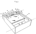
- Fig. 2 is a perspective view of a drawer,
- Figs. 3 and 4 are section views of a drawer under in use illustrated without end rollers;
- Fig. 5 and 6 show another embodiment of a drawer system of the present invention, wherein,
- Fig. 5 is a perspective view of a sheet roll-up device; and,
- Fig. 6 is a section view of a drawer in use.
- An embodiment of a drawer system of the present invention is described hereinafter with reference to the drawings.
- Fig. 1 is an analyzed perspective view of a sheet roll-up device A.
Numeral 1 is a rectangular sheet made of material such as flexible plastic one end of which is fixed to acore cylinder 2 so to be rolled up and thecore cylinder 2 is made of plastic. - Numeral 3a, 3b are holders which are symmetrical with each other comprising
band plates 4, 4' andvertical walls 5, 5' provided at the outer edge of theband plates 4, 4' at 90 degree angle relative to theband plates 4, 4'. One end of a supportinglever 6 of a predetermined length is connected to the inner surface of thevertical wall 5 so as to be parallel to theband plate 4. The other end of thelever 6 is engaged with acoil spring 8 by means of acollar 7. Onto the inner surface of another vertical wall 5', a supportinglever 9 is provided at the corresponding position to the supportinglever 6 and it is parallel to theband plate 4. - Further, one end of the
core cylinder 2 to which thesheet 1 is rolled up is engaged with the supportinglever 6, and the other end of thecore cylinder 2 is movably engaged with the supportinglever 9. By this construction, thesheet 1 tends to be rolled up to thecore cylinder 2 by means of the resilience of thecoil spring 8. - Further,
long perforations band plates 4, 4'. Thelong perforations core cylinder 2. Numeral 12, 12 are projecting pieces at the side edge of 4, 4' and haveperforations -
Numeral 14 is a drawer of which the top is open and numeral 15 is a housing frame of thedrawer 14. Thedrawer 14 comprises abottom wall 16, and afront wall 17, aback wall 18, aleft side wall 19 and aright side wall 19, each of which is provided on each side of thebottom wall 16. As shown in Figs. 2 and 3, thehousing frame 15 comprises abar 21 provided above anentrance 20 and areceiving plate 22 which supports thebottom wall 16 slidably. The sheet roll-up device A is placed inside of thebar 21 horizontally and fixed to thebar 21 at the projectingpieces 12 by means ofscrews 23. - The end of the
sheet 1 to be drawn out from the sheet roll-up device A is fastened to the edge of theback wall 18 so that the sheet covers over the top surface of thedrawer 14 when thedrawer 14 is enclosed in thehousing frame 15. - Furthermore, the width of the
sheet 1 and the length of thecore cylinder 2 corresponding thereto can be cut down so as to be the same length as the width of thedrawer 14. The length of thesheet 1 can also be cut down so as to be the same length as the depth of thedrawer 14. The distance between thevertical walls 5, 5' is determined by sliding theband plates 4, 4' . The length of the supportinglever 6 is kept shorter than that of thecore cylinder 2 in order to prevent any trouble in sliding theband plates 4, 4'. - In the above mentioned drawer system, when the
drawer 14 is being enclosed in thehousing frame 15, the upper surface of the drawer is covered with the extendedsheet 1 and the contents are prevented from projecting upward or overflowing, especially a thin paper is prevented from dropping off to the back of theback wall 18. - As the
sheet 1 is rolled up gradually when thedrawer 14 is withdrawn, the sheet does not cause any trouble in the movement of the drawer. - In addition, even in case the
drawer 14 is full of contents, thesheet 1 works just as a conveyer to convey the contents placed in the upper space in thedrawer 14 forward or backward accompanied with thesheet 1 as thedrawer 14 is drawn forward or backward. - The sheet roll-up device A may be fixed to the sides of the
housing frame 15 instead of being fixed to thebar 21. - Fig. 5 shows a sheet roll-up device A' of the second embodiment of the present invention.
Vertical walls 5, 5' haveperforations core shaft 25 projects outside of thevertical walls 5, 5' and each end of thecore shaft 25 is connected to aroller 28. A projecting part 26 of a supportingmember 27 is engaged with thecore cylinder 2. Therollers 28, 28on the end of the core might be substituted by knurling rollers to prevent slipping. - In this embodiment, the
rollers side walls drawer 14. In this condition, therollers drawer 14 and cause thesheet 1 to be extended or rolled-up. - The sheet roll-up device A' in this embodiment need not attach said
coil spring 8 to the supportingbar 6. Further, the supportingbar 6 can be shorter. - Further, several pieces of bendable and elastic band of narrow width may be attached to said
sheet 1 along longitudinal direction, which increase effect to push down contents inside of thedrawer 14. - Furthermore, said sheet is not necessarily made of elastic plastic plastic but may be made of other material if only it could be rolled up and it could cover the upper surface of the drawer.
- The foregoing relates to a preferred exemplary embodiment of the invention, it being understood that other variants and embodiments thereof are possible within the spirit and scope of the invention, the latter being defined by the appended claims.
Claims (3)
- A drawer system comprising a drawer, a sheet roll-up device including a core cylinder and a sheet of material secured at one end thereof to a back wall to cover the upper opening of the drawer in which the sheet material is rolled onto said core cylinder, said sheet roll-up device is placed above an entrance of the drawer so that said sheet can be withdrawn from the sheet roll-up device by the end of said sheet which is connected to the back wall of the drawer as the drawer is moved into place, said sheet is drawn out from the core cylinder to cover the open surface of the drawer when the drawn is pushed inside of the entrance, and said sheet is rolled onto said core cylinder of said sheet roll-up device when the drawer is withdrawn.
- A drawer system as claimed in claim 1, wherein said sheet of material is rolled onto said core cylinder by an elastic means.
- A drawer system of claim1, which includes rollers fixed to opposite ends of the core cylinder of said sheet roll-up device, said rollers are placed above upper surfaces of side walls of said drawer, wherein, the rollers roll with movement of the drawer so that the sheet is rolled onto said sheet roll-up device or withdrawn from it.
Applications Claiming Priority (2)
| Application Number | Priority Date | Filing Date | Title |
|---|---|---|---|
| JP127870/90 | 1990-05-17 | ||
| JP1990127870U JP2523000Y2 (en) | 1990-11-29 | 1990-11-29 | Extraction structure |
Publications (1)
| Publication Number | Publication Date |
|---|---|
| EP0488548A1 true EP0488548A1 (en) | 1992-06-03 |
Family
ID=14970685
Family Applications (1)
| Application Number | Title | Priority Date | Filing Date |
|---|---|---|---|
| EP91310438A Withdrawn EP0488548A1 (en) | 1990-11-29 | 1991-11-12 | A drawer system |
Country Status (3)
| Country | Link |
|---|---|
| US (1) | US5222789A (en) |
| EP (1) | EP0488548A1 (en) |
| JP (1) | JP2523000Y2 (en) |
Cited By (6)
| Publication number | Priority date | Publication date | Assignee | Title |
|---|---|---|---|---|
| WO1999043998A1 (en) * | 1998-02-24 | 1999-09-02 | Matsushita Refrigeration Company | Storage container for use in refrigerator |
| US7699414B1 (en) | 2007-03-30 | 2010-04-20 | Rhonda Shevrin | Drawer cover to prevent jams |
| EP2381814A2 (en) * | 2009-01-09 | 2011-11-02 | AutoMed Technologies, Inc. | Medication cabinetry |
| US9121197B2 (en) | 2009-01-09 | 2015-09-01 | Automed Technologies, Inc. | Cabinet system with improved drawer security |
| US9245405B2 (en) | 2009-01-09 | 2016-01-26 | Automed Technologies, Inc. | Cabinet system |
| US9345644B2 (en) | 2009-01-09 | 2016-05-24 | Arxium, Inc. | Medical cabinet access belt optimization system |
Families Citing this family (10)
| Publication number | Priority date | Publication date | Assignee | Title |
|---|---|---|---|---|
| JP3645884B2 (en) * | 2002-11-05 | 2005-05-11 | 松下電器産業株式会社 | Dishwasher |
| US8068932B2 (en) * | 2007-08-14 | 2011-11-29 | Roche Diagnostics Operations, Inc. | Access-controlled storage system |
| US8746908B2 (en) | 2010-01-27 | 2014-06-10 | Automed Technologies, Inc. | Medical supply cabinet with lighting features |
| US8506023B2 (en) * | 2010-03-26 | 2013-08-13 | Quickdrawer Llc | Handgun safe |
| KR101305738B1 (en) * | 2011-12-09 | 2013-09-06 | 현대자동차주식회사 | Rear bumper storage apparatus for vehicle |
| US8636329B1 (en) * | 2012-12-28 | 2014-01-28 | Lawrence J. Hug | Sliding cabinet drawer kit with drawer shield and method of installation |
| KR101716033B1 (en) * | 2015-06-16 | 2017-03-13 | 엘지전자 주식회사 | A refrigerator and a method controlling the same |
| JP7245064B2 (en) * | 2019-02-01 | 2023-03-23 | 林テレンプ株式会社 | vehicle storage box |
| CN115139922B (en) * | 2022-09-02 | 2022-12-02 | 江苏恒大警用装备制造有限公司 | On-vehicle police is with equipping safe strorage device |
| US20240260754A1 (en) * | 2023-02-07 | 2024-08-08 | Cameron Todd Gunn | Coffee Pod Holder |
Citations (5)
| Publication number | Priority date | Publication date | Assignee | Title |
|---|---|---|---|---|
| US1120028A (en) * | 1913-05-31 | 1914-12-08 | Dwight S Cole | Cabinet-drawer. |
| US1443352A (en) * | 1921-12-12 | 1923-01-30 | Dysthe Martinius | Drawer automatic cover placer |
| US2105783A (en) * | 1937-06-28 | 1938-01-18 | Gersten William | Cabinet |
| US4156549A (en) * | 1977-11-22 | 1979-05-29 | Clark Marvin A | Insect proof drawer |
| DE3202304A1 (en) * | 1982-01-26 | 1983-07-28 | Christian Miesen Fahrzeug- Und Karosseriewerk Gmbh, 5300 Bonn | Cabinet with removable drawer, especially for ambulances |
Family Cites Families (3)
| Publication number | Priority date | Publication date | Assignee | Title |
|---|---|---|---|---|
| US589159A (en) * | 1897-08-31 | Device for covering and protecting contents of drawers | ||
| US3982799A (en) * | 1975-05-27 | 1976-09-28 | Murray James M | Dish stabilizing mechanisms for dish-washing machines |
| US4021088A (en) * | 1976-04-07 | 1977-05-03 | Murray James M | Dish stabilizer for dish washing machines |
-
1990
- 1990-11-29 JP JP1990127870U patent/JP2523000Y2/en not_active Expired - Lifetime
-
1991
- 1991-11-12 EP EP91310438A patent/EP0488548A1/en not_active Withdrawn
- 1991-11-29 US US07/800,309 patent/US5222789A/en not_active Expired - Fee Related
Patent Citations (5)
| Publication number | Priority date | Publication date | Assignee | Title |
|---|---|---|---|---|
| US1120028A (en) * | 1913-05-31 | 1914-12-08 | Dwight S Cole | Cabinet-drawer. |
| US1443352A (en) * | 1921-12-12 | 1923-01-30 | Dysthe Martinius | Drawer automatic cover placer |
| US2105783A (en) * | 1937-06-28 | 1938-01-18 | Gersten William | Cabinet |
| US4156549A (en) * | 1977-11-22 | 1979-05-29 | Clark Marvin A | Insect proof drawer |
| DE3202304A1 (en) * | 1982-01-26 | 1983-07-28 | Christian Miesen Fahrzeug- Und Karosseriewerk Gmbh, 5300 Bonn | Cabinet with removable drawer, especially for ambulances |
Cited By (15)
| Publication number | Priority date | Publication date | Assignee | Title |
|---|---|---|---|---|
| WO1999043998A1 (en) * | 1998-02-24 | 1999-09-02 | Matsushita Refrigeration Company | Storage container for use in refrigerator |
| US7699414B1 (en) | 2007-03-30 | 2010-04-20 | Rhonda Shevrin | Drawer cover to prevent jams |
| EP2381814A2 (en) * | 2009-01-09 | 2011-11-02 | AutoMed Technologies, Inc. | Medication cabinetry |
| EP2381814A4 (en) * | 2009-01-09 | 2015-02-25 | Automed Technologies Inc | Medication cabinetry |
| US9111408B2 (en) | 2009-01-09 | 2015-08-18 | Automed Technologies, Inc. | Medication cabinetry |
| US9121197B2 (en) | 2009-01-09 | 2015-09-01 | Automed Technologies, Inc. | Cabinet system with improved drawer security |
| US9245405B2 (en) | 2009-01-09 | 2016-01-26 | Automed Technologies, Inc. | Cabinet system |
| US9345644B2 (en) | 2009-01-09 | 2016-05-24 | Arxium, Inc. | Medical cabinet access belt optimization system |
| US9511001B2 (en) | 2009-01-09 | 2016-12-06 | Arxium, Inc. | Medical cabinet access belt optimization system |
| US9536055B2 (en) | 2009-01-09 | 2017-01-03 | Arxium, Inc. | Cabinet system |
| EP3195758A1 (en) * | 2009-01-09 | 2017-07-26 | ARxIUM, Inc. | Medication cabinetry |
| US9770106B2 (en) | 2009-01-09 | 2017-09-26 | Arxium, Inc. | Cabinet system with improved drawer security |
| US9925123B2 (en) | 2009-01-09 | 2018-03-27 | Arxium, Inc. | Medical cabinet access belt optimization system |
| US10123944B2 (en) | 2009-01-09 | 2018-11-13 | Arxium, Inc. | Medical cabinet access belt optimization system |
| US10342740B2 (en) | 2009-01-09 | 2019-07-09 | Arxium, Inc. | Medical cabinet access belt optimization system |
Also Published As
| Publication number | Publication date |
|---|---|
| US5222789A (en) | 1993-06-29 |
| JP2523000Y2 (en) | 1997-01-22 |
| JPH0483034U (en) | 1992-07-20 |
Similar Documents
| Publication | Publication Date | Title |
|---|---|---|
| EP0488548A1 (en) | A drawer system | |
| US5680978A (en) | Baby bottle liner dispensing cabinet | |
| US3168275A (en) | Holder for boxed cleansing tissues | |
| US6453518B1 (en) | Holder for sheet material | |
| US4383657A (en) | Dispenser for products in sheet form | |
| US4650067A (en) | Conveyor | |
| US3140777A (en) | Card case | |
| US5238212A (en) | Beverage container support | |
| US4787334A (en) | House pet litter disposal device | |
| US5211458A (en) | Ribbed mat for placement on bottom of file cabinet drawer to prevent document slippage | |
| US2657873A (en) | Roll type paper dispensing cabinet | |
| US4998695A (en) | Multiple arrangeable strip support for a bag | |
| CA1222727A (en) | Container for photographic prints | |
| US4132380A (en) | Clip mechanism and wall retention device for cup dispensing housing or similar article | |
| US3840146A (en) | Paper towel dispenser | |
| US20070119082A1 (en) | Extensible Folder Tab | |
| US5366097A (en) | Recyclable material separating device | |
| US4869196A (en) | Coiled bookmark | |
| US5415279A (en) | Sleeving device, kit, and method | |
| US5425486A (en) | Wrap dispenser with compressible support | |
| GB2255925A (en) | Foil or film dispenser | |
| US3486711A (en) | Paper guide and holder | |
| GB2045726A (en) | A recording paper holder for use with an appliance such as an electronic calculator | |
| GB2195987A (en) | Dispensing device | |
| EP0599493A1 (en) | Kitchen roll dispenser |
Legal Events
| Date | Code | Title | Description |
|---|---|---|---|
| PUAI | Public reference made under article 153(3) epc to a published international application that has entered the european phase |
Free format text: ORIGINAL CODE: 0009012 |
|
| AK | Designated contracting states |
Kind code of ref document: A1 Designated state(s): DE FR GB IT SE |
|
| 17P | Request for examination filed |
Effective date: 19921123 |
|
| 17Q | First examination report despatched |
Effective date: 19940506 |
|
| STAA | Information on the status of an ep patent application or granted ep patent |
Free format text: STATUS: THE APPLICATION IS DEEMED TO BE WITHDRAWN |
|
| 18D | Application deemed to be withdrawn |
Effective date: 19941118 |