EP0444987A1 - Process for purifying high-temperature reducing gases and composite power plant with coal gasification - Google Patents
Process for purifying high-temperature reducing gases and composite power plant with coal gasification Download PDFInfo
- Publication number
- EP0444987A1 EP0444987A1 EP91400307A EP91400307A EP0444987A1 EP 0444987 A1 EP0444987 A1 EP 0444987A1 EP 91400307 A EP91400307 A EP 91400307A EP 91400307 A EP91400307 A EP 91400307A EP 0444987 A1 EP0444987 A1 EP 0444987A1
- Authority
- EP
- European Patent Office
- Prior art keywords
- gas
- sulfur compounds
- sulfur
- high temperature
- temperature reducing
- Prior art date
- Legal status (The legal status is an assumption and is not a legal conclusion. Google has not performed a legal analysis and makes no representation as to the accuracy of the status listed.)
- Granted
Links
Images


Classifications
-
- C—CHEMISTRY; METALLURGY
- C10—PETROLEUM, GAS OR COKE INDUSTRIES; TECHNICAL GASES CONTAINING CARBON MONOXIDE; FUELS; LUBRICANTS; PEAT
- C10J—PRODUCTION OF PRODUCER GAS, WATER-GAS, SYNTHESIS GAS FROM SOLID CARBONACEOUS MATERIAL, OR MIXTURES CONTAINING THESE GASES; CARBURETTING AIR OR OTHER GASES
- C10J3/00—Production of combustible gases containing carbon monoxide from solid carbonaceous fuels
-
- C—CHEMISTRY; METALLURGY
- C10—PETROLEUM, GAS OR COKE INDUSTRIES; TECHNICAL GASES CONTAINING CARBON MONOXIDE; FUELS; LUBRICANTS; PEAT
- C10K—PURIFYING OR MODIFYING THE CHEMICAL COMPOSITION OF COMBUSTIBLE GASES CONTAINING CARBON MONOXIDE
- C10K3/00—Modifying the chemical composition of combustible gases containing carbon monoxide to produce an improved fuel, e.g. one of different calorific value, which may be free from carbon monoxide
- C10K3/02—Modifying the chemical composition of combustible gases containing carbon monoxide to produce an improved fuel, e.g. one of different calorific value, which may be free from carbon monoxide by catalytic treatment
-
- C—CHEMISTRY; METALLURGY
- C10—PETROLEUM, GAS OR COKE INDUSTRIES; TECHNICAL GASES CONTAINING CARBON MONOXIDE; FUELS; LUBRICANTS; PEAT
- C10J—PRODUCTION OF PRODUCER GAS, WATER-GAS, SYNTHESIS GAS FROM SOLID CARBONACEOUS MATERIAL, OR MIXTURES CONTAINING THESE GASES; CARBURETTING AIR OR OTHER GASES
- C10J2300/00—Details of gasification processes
- C10J2300/16—Integration of gasification processes with another plant or parts within the plant
- C10J2300/164—Integration of gasification processes with another plant or parts within the plant with conversion of synthesis gas
- C10J2300/1643—Conversion of synthesis gas to energy
- C10J2300/165—Conversion of synthesis gas to energy integrated with a gas turbine or gas motor
-
- C—CHEMISTRY; METALLURGY
- C10—PETROLEUM, GAS OR COKE INDUSTRIES; TECHNICAL GASES CONTAINING CARBON MONOXIDE; FUELS; LUBRICANTS; PEAT
- C10J—PRODUCTION OF PRODUCER GAS, WATER-GAS, SYNTHESIS GAS FROM SOLID CARBONACEOUS MATERIAL, OR MIXTURES CONTAINING THESE GASES; CARBURETTING AIR OR OTHER GASES
- C10J2300/00—Details of gasification processes
- C10J2300/16—Integration of gasification processes with another plant or parts within the plant
- C10J2300/1671—Integration of gasification processes with another plant or parts within the plant with the production of electricity
- C10J2300/1675—Integration of gasification processes with another plant or parts within the plant with the production of electricity making use of a steam turbine
-
- Y—GENERAL TAGGING OF NEW TECHNOLOGICAL DEVELOPMENTS; GENERAL TAGGING OF CROSS-SECTIONAL TECHNOLOGIES SPANNING OVER SEVERAL SECTIONS OF THE IPC; TECHNICAL SUBJECTS COVERED BY FORMER USPC CROSS-REFERENCE ART COLLECTIONS [XRACs] AND DIGESTS
- Y02—TECHNOLOGIES OR APPLICATIONS FOR MITIGATION OR ADAPTATION AGAINST CLIMATE CHANGE
- Y02E—REDUCTION OF GREENHOUSE GAS [GHG] EMISSIONS, RELATED TO ENERGY GENERATION, TRANSMISSION OR DISTRIBUTION
- Y02E20/00—Combustion technologies with mitigation potential
- Y02E20/16—Combined cycle power plant [CCPP], or combined cycle gas turbine [CCGT]
- Y02E20/18—Integrated gasification combined cycle [IGCC], e.g. combined with carbon capture and storage [CCS]
-
- Y—GENERAL TAGGING OF NEW TECHNOLOGICAL DEVELOPMENTS; GENERAL TAGGING OF CROSS-SECTIONAL TECHNOLOGIES SPANNING OVER SEVERAL SECTIONS OF THE IPC; TECHNICAL SUBJECTS COVERED BY FORMER USPC CROSS-REFERENCE ART COLLECTIONS [XRACs] AND DIGESTS
- Y02—TECHNOLOGIES OR APPLICATIONS FOR MITIGATION OR ADAPTATION AGAINST CLIMATE CHANGE
- Y02P—CLIMATE CHANGE MITIGATION TECHNOLOGIES IN THE PRODUCTION OR PROCESSING OF GOODS
- Y02P20/00—Technologies relating to chemical industry
- Y02P20/10—Process efficiency
- Y02P20/129—Energy recovery, e.g. by cogeneration, H2recovery or pressure recovery turbines
Definitions
- the present invention relates to a process for purifying high-temperature reducing gases, such as the product gas from coal gasification etc., by employing a simultaneous adsorptive removal of carbon dioxide and sulfur compounds in dry system under conversion of carbon monoxide into hydrogen and carbon dioxide.
- the above process for purifying high-temperature reducing gases can be applied, for example, in multipurport composite coal gasification plants for effecting power generation together with production of gaseous raw materials, such as, hydrogen, chemical raw materials for the production of methanol etc.; in composite power plants with heavy oil gasification; and so on.
- the present invention relates also to composite power plants with coal gasification, in which the above process for purifying high-temperature reducing gases is employed.
- Finely crushed coal a is supplied together with a gasifying agent (air or oxygen) q to a coal gasifier furnace b to produce a combustible gas c composed mainly of carbon monoxide (CO) and hydrogen (H2).
- the combustible gas c contains extraneous substances, such as, fly ash, smoke dust, sulfur compounds, such as, hydrogen sulfide (H2S), carbonyl sulfide (COS) etc.
- the combustible gas c is passed through a dust remover d and the thus dust-removed gas e is desulfurized by a desulfurizer f to obtain a purified product gas g .
- the sulfur compounds removed in the desufurizer f is treated so as to convert them into elementary sulfur which is recovered.
- the product gas g is supplied as the fuel gas to the burner of a gas turbine i for driving a power generator j1 .
- the exhaust gas k from the gas turbine i is passed to a waste heat boiler l to recover the waste heat by generating steam for a steam turbine p installed with a steam condenser o for driving a power generator j2 , before it is discharged into the atmosphere from chimney n
- Such a coal gasification composite power plant produces a pressurized high-temperature reducing gas having a considerable heat of combustion and containing substantially no harmful component, which can thus be utilized for an efficient power generation.
- the exhaust gas from the chimney contains all of CO2 resulting from the coal gasification in the gasifier and from the combustion of CO in the burner. No special consideration as to recovering or putting CO2 aside of environmental hazard has been made.
- Fig. 4 illustrating a typical arrangement of conventional coal gasification composite power plant by a more specific flow diagram
- finely pulverized coal is supplied to a coal gasification furnace (21) and is gasified by air at a high pressure and high temperature into a combustible furnace gas composed mainly of CO, H2 and N2.
- the furnace gas is cooled by a heat economizer cooler (22) consisting of a group of heat exchangers whereby a heat recovery steam is generated by the sensible heat of the furnace gas, which is utilized in a recovery power generation unit.
- the gasifier effluent gas contains useless and harmful substanses of, for example, solid particles, such as, fly ash and smoke dust, and sulfur-containing gases, such as, H2S, COS and so on.
- a gas purifier (23) composed of a dust remover and a desulfurizer.
- the resulting purified product gas is supplied to a burner (24).
- the combustion gas from the burner (24) is conducted to a gas turbine (25) for driving a power generator (26) and an air compressor (27) for the burner combustion air.
- the turbine exhaust gas has still a high enthalpy which is recovered through a waste heat boiler (28) to generate a steam for driving a steam turbine (29) of a recovery power generator (30) with a steam condenser (31), before it is discharged out of the chimney.
- the heat recovery steam generated in the economizer cooler (22) mentioned above is utilized here for supplementing the supply steam for the steam turbine (29).
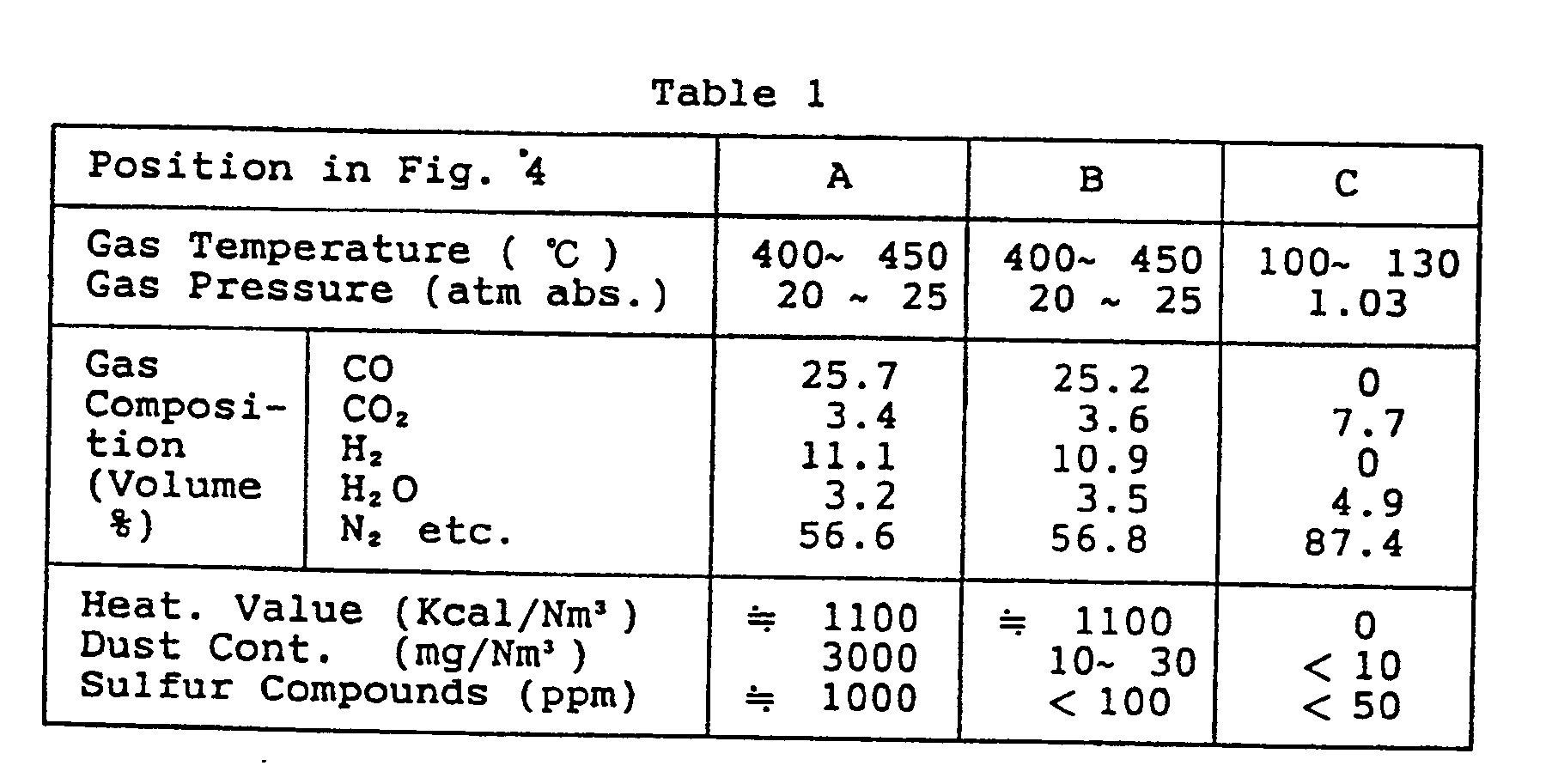
- the composition of the furnace effluent gas from the coal gasification furnace (21) at the position A of the palnt shown in Fig. 4 is, for example, as given in Table 1 below. Since the furnace effluent gas has a considerably high content of solid matters, such as, smoke dust, fly ash and so on, and high level of SO x concentration not permitted to meet the requirement for environmental protection, it has to be subjected to purification in the gas purifier (23) by dust removal and desulfurization.
- the dry system gas purifier consists in dry dust removal and dry desulfurization at a high temperature in the range from 300 to 800 °C without employing any absorbing liquid.
- the desulfurization is effected using a fixed bed filter with an iron oxide absorbent.
- a typical composition of the gas at the position indicated by B in Fig. 4 after passing through such a dry gas purifier (23) is, for example, as given also in Table 1.
- a typical composition of the exhaust gas of the waste heat boiler (28) at the position indicated by C in Fig. 4 is as given also in Table 1.
- the heating value per gas volume of the gasification furnace gas (or the purified product gas ) is increased ( about 2500 Kcal/Nm3), so that the volume of the product gas may amount to about two-fold of that of air-burning.
- the essential problem of CO2 removal from the chimney gas is yet not solved.
- the removal of CO2 may be effected in the gas line directly after the gasification furnace exit or in the gas line after the waste heat boiler exit (in the stack gas).
- the former can be attained economically with a compact apparatus with lower energy consumption, since the volume of the gas to be treated may be 1/2 or less of the latter.
- CO carbonaceous gas components
- CO2 content being in general below 5 %.
- nearly the entire CO content may be converted into CO2 and H2 by reacting it with steam (H2O).
- CO + H2O ⁇ CO2 + H2 may be employed.
- control of the amount of H2O to be injected into the reaction system and of gas temperature during the reaction for effective preservation of the catalyst activity and so on should be designed concretely.
- a dry CO2 removal is employed.
- PSA pressure swing adsorption
- a molecular sieve adsorbent for a simultaneous adsorption of CO2 and sulfur compounds, such as H2S etc.
- H2S sulfur compounds
- adsorption technique in general, the lower the adsorption temperature, the higher will be the adsorption efficiency.
- a coal gasification composite power plant should operate at a temperature as high as possible, in order to achieve a high energy efficiency of the plant.
- CO2 In order to dispose of CO2 and H2S adsorbed on the molecular sieve in PSA unit, these two components should be desorbed separately. It is possible to convert the desorbed H2S into elementary sulfur (S) by the Claus process. CO2 can be disposed of by fixation by disposal thereof in deep sea or deep earth.
- the first object of the present invention is to provide an economical process for purifying high temperature reducing gases which permits to solve the existing problems described above.
- the first aspect of the present invention for attaining the above first object resides in a process for purifying high temperature reducing gases by removing sulfur compounds contained in such reducing gases by dry adsorption on adsorbents, which comprises subjecting the high temperature reducing gas to a catalytic CO-shift reaction in a reactor having a corresponding catalyst and equipped with a heat recovery means for controlling the gas temperature while injecting steam into the high temperature reducing gas, in order to convert the content of CO in the high temperature reducing gas into CO2, effecting the removal of sulfur compounds from the gas exhausted from the CO-shift reactor by simultaneous adsorption of them together with CO2 on an adsorbent, while controlling the temperature of the gas using the heat recovery means of the reactor, and separating the thus adsorbed CO2 from the adsorbed sulfur compounds by desorption under control of the temperature and pressure of desorption to recover them.
- the second aspect of the present invention resides in a process for purifying high temperature reducing gases according to the above first aspect, which comprises supplying the sulfur compounds separated from CO2 to a Claus process sulfur recovery unit to convert the content of H2S in the sulfur compounds into elementary sulfur, which is recovered by extracting out of the unit, subjecting the exhaust from the Claus process unit to reduction by the H2 of the product gas to reduce other sulfur compounds and the residual sulfur into H2S and separating and returning the so formed H2S to the Claus process sulfur recovery unit, while the rest of the Claus process exhaust is disposed of by, for example, burning.
- the second object of the present invention is to provide a composite power plant with coal gasification capable of removing CO2 at a high efficiency with minimum energy loss.
- the third aspect of the present invention for achieving the above second object resides in a composite power plant with coal gasificatioon having installed a coal gasification furnace, a gas purifier for removing impurities from the furnace gas produced in the coal gasification furnace, a gas turbine power generation unit having a burner for burning the product gas purified in said gas purifier, a waste heat boiler for recovering the sensible heat of the exhaust gas from the gas turbine of said gas turbine power generation unit by generating steam and a steam turbine power generation unit driven by the said steam generated in the waste heat boiler, which composite power plant comprises a reactor for converting CO in the gas purified by said gas purifier into CO2 disposed between said gas purifier and said burner of the gas turbine power generation unit and a dry CO2 removal unit for removing CO2 from the gas leaving said reactor.
- the purified furnace gas from the gas purifier is subjected to Claus reaction under injection of a requisite amount of steam into the gas to convert substantially entire content of CO into CO2 and the resulting product gas is supplied to the burner of the gas turbine power generation unit after removal of the CO2 content by a dry CO2 removal unit, whereby the following technical advantages are realized:
- Fig. 1 is a flow diagram of the system for purifying high temperature reducing gases according to the present invention.
- Fig. 2 is a flow diagram of an embodiment of coal gasification composite power plant according to the present invention.
- Fig. 3 is a flow diagram of an exemplary coal gasification composite power plant of prior art.
- Fig. 4 is a flow diagram of another exemplary coal gasification composite power plant of the prior art.
- the CO-shift reactor operates to convert CO contained in the high temperature reducing gas, such as, coal gasification producer gas, into CO2 according to the reaction scheme (1) under the use of a catalyst.
- the CO-shift reactor is equipped with a heat recovery means for controlling the temperature of the reaction gas, so that attainment of compact design of the plant and reduction of the energy consumption is permitted.
- the higher the temperature of the combustion gas the higher will be the power generation efficiency.
- a catalyst system of Fe-Cr, Cu-Zn or Cu-Cr is employed for this reaction, a thermal deterioration of the catalyst may be brought about when the temperature of the catalyst bed is high.
- the reaction gas temperature at the exit of the reactor may preferably be below about 500 °C on account of the catalyst life.
- Temperature elevation of the reaction gas by the heat evolution due to the exothermal reaction may be controlled by controlling the temperature of the reactor exhaust gas by the heat recovery means installed therein.
- the reaction gas temperature within the reactor may be controlled by corresponding operation of the heat recovery means of the CO-shift reactor. Namely, the temperature of the exhaust gas of the reactor can be maintained below a determined temperature, for example, 500°C .
- the conversion of CO into CO2 can easily be controlled by adjusting the amount of steam injected into the purified furnace gas supplied to the CO-shift reactor. By controlling the amount of steam injected so as to correspond to each requisite CO conversion, it is able to minimize the residual H2O in the gas exhausted from the CO-shift reactor, whereby any undesirable influence of H2O on the installations downstream thereof.
- the adsorbing power to the adsorbent is higher for H2S than CO2.
- the requisite amount of adsorbent can be determined from the designed CO2 concentration in the first aspect of the present invention, since the concentration of CO2 in the gas to be treated is in general about 50- to 500-fold of that of the sulfur compounds.
- a heat recovery means is disposed upstream of the unit of dry adsorptive removal of CO2 and the sulfur compounds, in order to decrease the gas temperature while attaining an energy recovery from its sensible heat to controll the inlet gas temperature of the dry adsorptive removal unit to, for example, about 250 - 300 °C for effecting a highly efficient adsorption of CO2 and the sulfur compounds.
- pure product gas having the combustible component essentially of H2 is obtained.
- This product gas is burnt in the burner of a gas turbine for power generation exhausting substantially a CO2-free combustion gas, whereby any emission of CO2 into the atmosphere may be prevented.
- CO2 and the sulfur compounds removed from the product gas by, such as, PSA unit can be separately desorbed by making use of the difference in the adsorbing power of the adsorbent to the adsorbate between CO2 and the sulfur compounds.
- the relative adsorbing power of a usual adsorbent is greater to H2S than to CO2, so that the adsorption will occur first for H2S and, after the adsorption equillibrium for H2S has been reached, the adsorption of CO2 will commence. It is therefore important not only to choose an adsorbent having greater adsorbing power to H2S but also to control the amount of charge of the adsorbent that adsorbs preferentially H2S.
- the sulfur compounds such as H2S and so on, can easily be separated in a concentrated form from CO2 by desorbing it from the adsorbent by reducing the pressure up to a determined value, while recovering the desorbed CO2 as a high purity gas.
- the conversion of CO contained in the high temperature reducing gas into CO2 is effected in a CO-shift reactor according to the first aspect of the present invention, wherein control of the conversion of CO can be effected with simultaneous attainment of mimization of the residual amount of H2O left unreacted in the exhaust from the reactor, by adjusting the amount of steam injected into the supply gas to the CO-shift reactor.
- the shift reaction of CO into CO2 is achieved upstream of the burner of gas turbine, so that the amount of gas to be subjected to the shift reaction is kept at a minimum with less consumption of the operation energy and a compact arrangement of the installations can also be realized.
- the temperature of the reaction gas in the CO-shift reactor can be controlled by means of the heat recovery means of the reactor, so that the CO-shift reaction is effected efficiently at a desirable temperature.
- the temperature of the exhaust gas from the reactor is thereby reduced to a required level for realizing efficient dry adsorptive removal of CO2 and the sulfur compounds from the reactor exhaust gas and easy separative desorption of them from the adsorbent.
- the removal of CO2 is effected simultaneously with the removal of the sulfur compounds in a dry adsorptive way with scarce energy consumption in purifying high temperature reducing gases.
- the sulfur compounds including H2S removed from the high temperature reducing gases are supplied to a Claus process sulfur recovery unit, in which H2S is subjected first to a partial oxidation by oxygen followed by conversion into elementary sulfur using a Claus catalyst to recover it as elementary sulfur.
- the exhaust from the Claus sulfur recovery unit contains elementary sulfur, SO2 and unreacted H2S.
- gaseous elementary sulfur is converted to liquid sulfur mist which is collected as liquid sulfur.
- the residual gas contains thus H2S, SO2, the rest of gaseous elementary sulfur and entrained sulfur mist. All these sulfureous substances other than H2S are then subjected to reduction by the hydrogen gas contained in the high temperature reducing gas according to the following reaction schemes (2) and (3): SO2 + 3H2 ⁇ H2S + 2H2O S + H2 ⁇ H2S
- H2S separation of H2S from other components, such as N2, CO2 and so on is realized by, for example, PSA technique.
- H2S is returned to the Claus process sulfur recovery unit to recover it in the form of elementary sulfur, while the gaseous rest remaining after H2S has been separated, which contains a trace remainder of sulfur compounds such as H2S and so on, is disposed of into the atmosphere after it has been tereated by, for example, burning to convert into SO2.
- the second aspect of the present invention incorporates, in addition to the features of the first aspect of the present invention, a further feature of recovering sulfur comounds left after removal of H2S by reducing them into H2S by the hydrogen of the high temperature reducing gas and recirculating it to the Claus process sulfur recovery unit.
- a high temperature reducing gas 1 consisting of a coal gasification furnace gas containing gaseous sulfur compounds, such as, H2S, COS and so on, and particulate impurities of smoke etc. is first treated by dust removal through a dry dust removal unit 2 operable at high temperatures, such as for example, a ceramic porous filter.
- a steam required for effecting a CO-shift reaction is injected into the dust-removed gas in a gas line 3 from a steam supply line 45.
- the thus dust-removed and wetted reducing gas is supplied via a gas line 4 to a CO-shift reactor 5 having inflow side and outflow side reaction zones 5a and 5b respectively containing each a layer of catalyst based on Fe-Cr, Cu-Zn or Cu-Cr for effecting the conversion of CO and H2O into H2 and CO2.
- the reaction gas which has left the reaction zone 5a is conducted to a heat recovery boiler 6, where the gas is cooled to a temperature effective to avoid superheating of the catalyst layer while recovering the reaction heat by generating steam.
- the gas passed through the heat recovery boiler 6 is then passed to the reaction zone 5b, where a supplemental CO-conversion is effected.
- the heat recovery boiler 6 the temperature of the gas exhausted from the reactor 5 is maintained at a lower level of not exceeding above 500°C , whereby a thermal deterioration of catalyst activity can be prevented with smooth conduction of the conversion reaction.
- the gas leaving the CO-shift reactor of which combustible fuel component consists now essentially of hydrogen with scarce residual content of CO, is then supplied to a dry adsorptive removal unit 10 for removing CO2 and the sulfur compounds.
- the dry adsorptive removal unit consists of a dry adsorption apparatus filled with an adsorbent for adsorbing CO2 and sulfur compounds and operable on a basis of dry PSA technique.
- CO2 and the sulfur compounds contained in the gas leaving the CO-shift reactor are adsorbed on the adsorbent at a high efficiency and are thus removed from the product gas at an adsorption temperature reduced to 250 - 300°C .
- the adsorbent substantially saturated with the adsorbed CO2 and the sulfur compounds removed from the product gas is then regenerated by desorbing these adsorbates by relieving the pressure of the adsorption removal unit 10 at an elevated temaprature with or without sweeper gas.
- the desorption gas containing CO2 and sulfur compounds at high concentration discharged from the adsorption unit 10 is supplied to a CO2 separator 13 composed of an adsorption bed filled with an adsorbent with higher adsorbing power to sulfur compounds than CO2 and operable by the PSA technique.
- CO2 is separated from the separator 13 while the sulfur compounds are retained adsorbed on the adsorbent, whereby separation of CO2 in a highly pure state is attained under recovery thereof via a delivery line 30.
- the sulfur compounds are then desorbed from the CO2 separator 13 and the desorption gas having a high H2S content is supplied via a supply line 14 to a Claus process sulfur recovery unit 15, where it is converted into elementary sulfur which is recovered as liquid sulfur outside the unit via a discharge line 31.
- the residual gaseous exhaust from the Claus sulfur recovery unit 15 is supplied via a supply line 16 to a tail gas reducing reactor 17 filled with a reduction catalyst based on Co-Ni, Ni-Mo or so on, where the sulfur compounds other than H2S are reduced by the hydrogen of the product gas into H2S.
- the gas leaving the reducing reactor 17 through a delivery line 18 is conducted to a H2S separator 19 operative in a similar manner as the CO2 separator 13, where the gas is separated into an H2S-rich gas 20 and a remainder gas 42.
- the H2S-rich gas 20 is returned to the Claus sulfur recovery unit 15 after it has been compressed to the pressure of Claus sulfur recovery unit by a blower 41, while the remainder gas 42 is disposed of into the atmosphere via a discharge line 44 after burning any combustible component therein into oxide.
- the heat recovery boiler 6 serves for adjusting the temperature of the catalyst layer of the follower reaction zone 5b on realizing the CO-shift reaction in two stages and has a feed line 46 for the boiler feed water and a steam delivery line 47.
- a line a is branched to inject the steam into the furnace gas entering the CO-shift reactor 5.
- the boiler feed line 46 is branched to a feed line b for another heat recovery boiler 8, of which steam generated is joined to the steam delivery line 47 via a line c .
- Example 1 it is attained to substantially reduce the amount of CO2 discharged from gas turbine into the atmosphere with simultaneous prevention of emission of sulfur compounds, by converting the essential portion of CO contained in high temperature reducing gasses into CO2 and removing the substantial portion of CO2 by dry adsorption on an adsorbent together with sulfur compounds under recovery of them in a pure utlizable form.
- gas turbine for power generation is advantageous as compared to the use of conventional coal dust burning boiler as to the removal of CO2, in view of the fact that the amount of exhaust gas from the coal gasification furnace for producing gas turbine fuel gas amounts to about 1/2, in the case of air-burning, and to about 1/4, in the case of oxygen-burning, of the amount of exhaust gas from the coal dust burning boiler furnace.
- the sulfur compounds and CO2 separated from the product gas are recovered in a pure and utilizable form as elementary sulfur and pure CO2 gas.
- the remainder gas 42 having scarce content of residual H2S from the H2S separator 19 is disposed of into the atmosphere, after it has been treated into a practically innoxious form by, for example, burning in an incinerator 43.
- Example 2 bolow The experimental data obtained in Example 1 above are recited in Table 2 bolow, wherein the values are given for temperature in°C , pressure in atmosphere absolute, heating value in Kcal/Nm3, dust content in mg/Nm3, sulfur compound concentration in ppm and the volume of gas generated in Nm3/hr x 109 respectively.
- the high temperature reducing gases to be treated according to the present invention are not restricted only to the furnace gas from a coal gasification furnace but are inclusive of every high temperature reducing gas containing CO and sulfur compounds.
- This Example describes an embodiment of the third aspect of the present invention exemplified by the schematic flow diagram of Fig. 2.
- the same element or constituent part as shown in Fig. 4 is designated with the same numeral symbol as in Fig. 4 and explanation therefor is omitted.
- the gas generated in a coal gasification furnace 21 (especially that of compressed air burning) is supplied to a gas purifier 23 and is purified here before it is introduced into a CO-shift reactor 36.
- a steam from, for example, a middle or low pressure steam extraction of turbine is injected into the furnace gas.
- a CO2 separator 37 is disposed downstream of the CO-shift reactor 36.
- the gas exhausted from the exit of the gas purifier 23 is a combustible gas composed mainly of CO, H2 and N2 (See Table 3, column for the position B), of which composition in the case of air-burning is typically about 25 % of CO and about 10 % of H2.
- the shift reaction of CO into CO2 is an exothermic raction, so that the reaction will be facilitated if the temperature of reaction mixture is lower as deduced from the equillibrium therefor.
- the reaction may be conducted advantageously at a temperature of about 300 - 500°C .
- the gas exhausted from the CO-shift reactor 36 is a combustible gas composed mainly of H2, CO2 and N2 with some CO and H2O (See Table 3, column for the position C).
- This gas is supplied to a CO2 separator 27, wherein CO2 is removed from the main stream of the product gas to be fed to the gas turbine 25, while recovering CO2 from the CO2 separator by means of a suitable CO2 recovery unit.
- the fuel gas for the gas turbine consists now mainly of hydrogen and nitrogen in the case of air-burning and essentially of only hydrogen in the case of oxygen-burning. Therefore, any formation of CO2 upon operation of a gas turbine is steeply decreased as seen from Table 3, column for the position D of Fig. 2, besides the stability of combustion in the gas turbine burner to be attained as explained above.
- CO2 separator 37 there may be employed advantageously those operable on a physical principle on the basis of PSA technique.
- the CO2 separated from the main stream of the gas is present in a compressed condition, so that it may be possible to recover therefrom a further energy by employing, for example, a gas expander 38 to attain supplemental power generation.
- a gas expander 38 to attain supplemental power generation.
- CO2 separator 37 based on PSA technique permits to remove residual sulfur compounds, such as H2S, COS etc., which have not been removed in the dry desulfurization unit in the gas purifier 23 and are in a concentration of about 30 - 100 ppm, leaving a clean product gas (position D of Fig. 2) which is clean enough to be allowed to use even for a fuel cell.
- the sulfur compounds desorbed from the CO2 separator 37 are collected in a sulfur compound separator 39 and are separated from CO2.
- the desorbed CO2 free from sulfur compounds is recovered in a highly pure state after it has passed a gas expander 38.
- the sulfur compounds collected by the sulfur compound separator 39 are returned to the gas purifier 23.
- a recovery of the heat of reaction in the CO-shift reactor can be attained by installing heat recovery boilers 32, 33 in the CO-shift reactor.
- the experimental data obtained in Example 2 above are recited in Table 3 bolow, wherein the values given are based on the same units as given in Table 2.
Landscapes
- Chemical & Material Sciences (AREA)
- Engineering & Computer Science (AREA)
- Combustion & Propulsion (AREA)
- Oil, Petroleum & Natural Gas (AREA)
- Organic Chemistry (AREA)
- Chemical Kinetics & Catalysis (AREA)
- General Chemical & Material Sciences (AREA)
- Industrial Gases (AREA)
- Treating Waste Gases (AREA)
Abstract
Description
- The present invention relates to a process for purifying high-temperature reducing gases, such as the product gas from coal gasification etc., by employing a simultaneous adsorptive removal of carbon dioxide and sulfur compounds in dry system under conversion of carbon monoxide into hydrogen and carbon dioxide.
- The above process for purifying high-temperature reducing gases can be applied, for example, in multipurport composite coal gasification plants for effecting power generation together with production of gaseous raw materials, such as, hydrogen, chemical raw materials for the production of methanol etc.; in composite power plants with heavy oil gasification; and so on.
- Thus, the present invention relates also to composite power plants with coal gasification, in which the above process for purifying high-temperature reducing gases is employed.
- In conventional multipurport gasification-power generation composite plants for producing various product gases, such as, methane, methanol, ammonia and so on, by gasifying heavy oils, coal, natural gas etc., removal of extraneous gases, such as, carbon dioxide (CO₂), hydrogen sulfide (H₂S) and so on, has been incorporated in wet system. There has been proposed no practical use of dry purification system. A typical flow diagram of such conventional composite power plants with coal gasification is given in the appended Fig 3.
- Finely crushed coal a is supplied together with a gasifying agent (air or oxygen) q to a coal gasifier furnace b to produce a combustible gas c composed mainly of carbon monoxide (CO) and hydrogen (H₂). The combustible gas c contains extraneous substances, such as, fly ash, smoke dust, sulfur compounds, such as, hydrogen sulfide (H₂S), carbonyl sulfide (COS) etc. To remove such extraneous substances, the combustible gas c is passed through a dust remover d and the thus dust-removed gas e is desulfurized by a desulfurizer f to obtain a purified product gas g. The sulfur compounds removed in the desufurizer f is treated so as to convert them into elementary sulfur which is recovered. The product gas g is supplied as the fuel gas to the burner of a gas turbine i for driving a power generator j₁. The exhaust gas k from the gas turbine i is passed to a waste heat boiler l to recover the waste heat by generating steam for a steam turbine p installed with a steam condenser o for driving a power generator j₂, before it is discharged into the atmosphere from chimney n
- Such a coal gasification composite power plant produces a pressurized high-temperature reducing gas having a considerable heat of combustion and containing substantially no harmful component, which can thus be utilized for an efficient power generation. Here, however, the exhaust gas from the chimney contains all of CO₂ resulting from the coal gasification in the gasifier and from the combustion of CO in the burner. No special consideration as to recovering or putting CO₂ aside of environmental hazard has been made.
- It has in recent years been emphasized to cope with the requirement of taking a countermeasure against the global problem of warming of earth due to increase in the CO₂ concentration in the atmosphere.
- Explaining such a stand of the technique by reference to the appended Fig. 4 illustrating a typical arrangement of conventional coal gasification composite power plant by a more specific flow diagram, finely pulverized coal is supplied to a coal gasification furnace (21) and is gasified by air at a high pressure and high temperature into a combustible furnace gas composed mainly of CO, H₂ and N₂. The furnace gas is cooled by a heat economizer cooler (22) consisting of a group of heat exchangers whereby a heat recovery steam is generated by the sensible heat of the furnace gas, which is utilized in a recovery power generation unit. The gasifier effluent gas contains useless and harmful substanses of, for example, solid particles, such as, fly ash and smoke dust, and sulfur-containing gases, such as, H₂S, COS and so on. To remove these harmful substances, it is passed through a gas purifier (23) composed of a dust remover and a desulfurizer. The resulting purified product gas is supplied to a burner (24). The combustion gas from the burner (24) is conducted to a gas turbine (25) for driving a power generator (26) and an air compressor (27) for the burner combustion air. The turbine exhaust gas has still a high enthalpy which is recovered through a waste heat boiler (28) to generate a steam for driving a steam turbine (29) of a recovery power generator (30) with a steam condenser (31), before it is discharged out of the chimney. The heat recovery steam generated in the economizer cooler (22) mentioned above is utilized here for supplementing the supply steam for the steam turbine (29).
- As seen, conventional coal gasification power plants were designed exclusively for seeking a high efficiency and high performance of the plant and no special consideration had been paid for the removal of CO₂ in the exhaust gas. This applies also for the heavy oil gasification composite power plants.
- The composition of the furnace effluent gas from the coal gasification furnace (21) at the position A of the palnt shown in Fig. 4 is, for example, as given in Table 1 below. Since the furnace effluent gas has a considerably high content of solid matters, such as, smoke dust, fly ash and so on, and high level of SOx concentration not permitted to meet the requirement for environmental protection, it has to be subjected to purification in the gas purifier (23) by dust removal and desulfurization.
- While there had been proposed in the practice a combined gas purification apparatus in wet system, in which dust removal with a permanent scrubber operated at around the ordinary temperature (below 100 °C ) and absorptive desulfurization with a chemical absorption liquid are combined, a dry system has heretofore been employed in the point of view of improvement of thermal efficiency, since it has been accepted as advantageous for power generation. The dry system gas purifier consists in dry dust removal and dry desulfurization at a high temperature in the range from 300 to 800 °C without employing any absorbing liquid. The desulfurization is effected using a fixed bed filter with an iron oxide absorbent. A typical composition of the gas at the position indicated by B in Fig. 4 after passing through such a dry gas purifier (23) is, for example, as given also in Table 1. A typical composition of the exhaust gas of the waste heat boiler (28) at the position indicated by C in Fig. 4 is as given also in Table 1.
- If a CO₂ removal unit is incorporated in the conventional composite power plant as explained above, the following problems will occur:
- In the case of installation of a dry CO₂ removal unit in the gas line after the exit of the waste heat boiler (28), a larger CO₂ removal unit must be employed regardless of the type of the CO₂ removal unit, since the exhaust gas volume from a gas turbine amounts in general to about two-fold of that from a boiler. Moreover, an insertion of an extraneous installation in the gas line after the gas turbine exit will bring about a decrease in the power output and lowering of the performance of the gas turbine (25) due to increase of the exhaust back pressure of the gas turbine.
- In the case of installation of a dry CO₂ removal unit in the gas line between the gasification furnace (21) and the gas turbine (25), an efficient CO₂ removal may be attained, since the volume of the gas to be treated may in general be about 1/4 of the volume of the gas turbine exhaust at a high pressure of 20 - 40 atm. Here, however, an essential increase in the over-all CO₂ removal efficiency may not be expectable, since the proportion of CO₂ amounts in general to about 20 - 25 % of the total carbonaceous gas components for air burning system. In addition, some decrease in the power output of the gas turbine (25) in correspondence to the amount of CO₂ removed.
- In the case of oxygen-burning gasification plant employing oxygen or an oxygen-enriched air as the gasifying agent, the heating value per gas volume of the gasification furnace gas (or the purified product gas ) is increased ( about 2500 Kcal/Nm³), so that the volume of the product gas may amount to about two-fold of that of air-burning. Here also, the essential problem of CO₂ removal from the chimney gas is yet not solved.
- In the case of oxygen-burning, an additional disadvantage of requirement of installation of oxygen plant is brought about.
- In the coal gasification composite power plants of the prior art, the removal of CO₂ may be effected in the gas line directly after the gasification furnace exit or in the gas line after the waste heat boiler exit (in the stack gas). The former can be attained economically with a compact apparatus with lower energy consumption, since the volume of the gas to be treated may be 1/2 or less of the latter. Here however, as explained previously, almost all of the carbonaceous gas components (CO, CO₂ etc.) is CO, with CO₂ content being in general below 5 %. In designing the composite power plant with installation of CO₂ removal in this location, nearly the entire CO content may be converted into CO₂ and H₂ by reacting it with steam (H₂O).
- For realizing this plant design, the so-called CO-shift reaction of the reaction scheme (1)

- Incorporation of an wet system, such as wet absorption with monoethanolamine proposed previously in multipurport composite plant may not be practical, since the decrease in the gas temperature upon wet CO₂ removal obstructs the employment of gas turbine power generator.
- Thus, according to the present invention, a dry CO₂ removal is employed. Here, it may be practical to employ the so-called "pressure swing adsorption" (PSA) with a molecular sieve adsorbent for a simultaneous adsorption of CO₂ and sulfur compounds, such as H₂S etc. In an adsorption technique, in general, the lower the adsorption temperature, the higher will be the adsorption efficiency. However, a coal gasification composite power plant should operate at a temperature as high as possible, in order to achieve a high energy efficiency of the plant.
- In order to dispose of CO₂ and H₂S adsorbed on the molecular sieve in PSA unit, these two components should be desorbed separately. It is possible to convert the desorbed H₂S into elementary sulfur (S) by the Claus process. CO₂ can be disposed of by fixation by disposal thereof in deep sea or deep earth.
- The first object of the present invention is to provide an economical process for purifying high temperature reducing gases which permits to solve the existing problems described above.
- The first aspect of the present invention for attaining the above first object resides in a process for purifying high temperature reducing gases by removing sulfur compounds contained in such reducing gases by dry adsorption on adsorbents, which comprises subjecting the high temperature reducing gas to a catalytic CO-shift reaction in a reactor having a corresponding catalyst and equipped with a heat recovery means for controlling the gas temperature while injecting steam into the high temperature reducing gas, in order to convert the content of CO in the high temperature reducing gas into CO₂, effecting the removal of sulfur compounds from the gas exhausted from the CO-shift reactor by simultaneous adsorption of them together with CO₂ on an adsorbent, while controlling the temperature of the gas using the heat recovery means of the reactor, and separating the thus adsorbed CO₂ from the adsorbed sulfur compounds by desorption under control of the temperature and pressure of desorption to recover them.
- The second aspect of the present invention resides in a process for purifying high temperature reducing gases according to the above first aspect, which comprises supplying the sulfur compounds separated from CO₂ to a Claus process sulfur recovery unit to convert the content of H₂S in the sulfur compounds into elementary sulfur, which is recovered by extracting out of the unit, subjecting the exhaust from the Claus process unit to reduction by the H₂ of the product gas to reduce other sulfur compounds and the residual sulfur into H₂S and separating and returning the so formed H₂S to the Claus process sulfur recovery unit, while the rest of the Claus process exhaust is disposed of by, for example, burning.
- According to the above first and the second aspects of the present invention, the following practical advantages can be achieved:
- (a) By the employment of dry adsorption means for the removal of CO₂ and sulfur compounds from a high temperature reducing gas under conversion of the CO content of the gas into CO₂, a simultaneous removal of CO₂ and the sulfur compounds contained in the reducing gas can be effected with lower energy consumption.
- (b) By controlling the amount of injection of H₂O into the high temperature reducing gas for the CO-shift reaction to be the requisite minimum in accordance with each specific required conversion of CO, undesirable influence of H₂O on the installations downstream the reactor can be rendered minimum.
- (c) By installing a heat recovery means for controlling the reaction temperature in the CO-shift reactor, a high conversion of CO into CO₂ is attained, with simultaneous attainment of protection of the catalyst by maintaining the gas temperature below a determined value of, for example, 500 °C .
- (d) All the sulfur compounds separated can be converted into elementary sulfur (S) at a high conversion rate and the separated CO₂ can be recovered in a high purity.
- (e) The process for purifying the high temperature reducing gases can be applied also for producing chemical raw materials, since a high removal rate is attained both for CO₂ and for the sulfur compounds.
- The second object of the present invention is to provide a composite power plant with coal gasification capable of removing CO₂ at a high efficiency with minimum energy loss.
- The third aspect of the present invention for achieving the above second object resides in a composite power plant with coal gasificatioon having installed a coal gasification furnace, a gas purifier for removing impurities from the furnace gas produced in the coal gasification furnace, a gas turbine power generation unit having a burner for burning the product gas purified in said gas purifier, a waste heat boiler for recovering the sensible heat of the exhaust gas from the gas turbine of said gas turbine power generation unit by generating steam and a steam turbine power generation unit driven by the said steam generated in the waste heat boiler, which composite power plant comprises a reactor for converting CO in the gas purified by said gas purifier into CO₂ disposed between said gas purifier and said burner of the gas turbine power generation unit and a dry CO₂ removal unit for removing CO₂ from the gas leaving said reactor.
- According to the above third aspect of the present invention, the purified furnace gas from the gas purifier is subjected to Claus reaction under injection of a requisite amount of steam into the gas to convert substantially entire content of CO into CO₂ and the resulting product gas is supplied to the burner of the gas turbine power generation unit after removal of the CO₂ content by a dry CO₂ removal unit, whereby the following technical advantages are realized:
- (a) Substantially all the CO₂ formed in the coal gasification composite power plant can be separated from the product gas with scarce consumption of the plant private power.
- (b) The carbonaceous fuel components are converted into CO₂ and the so formed CO₂ can be separated at a high temperature and high pressure (350 - 500 °C, 20 - 40 atm) easily with a very low energy consumption.
- (c) By the removal of CO₂ from the product gas before it is burnt in the burner of the gas turbine, the combustion stability is increased, since the intrinsic fuel component consists thus exclusively of H₂.
- (d) Upon desorption of CO₂, an additional power recovery through a gas expander can be obtained.
- (e) Due to the depletion of the sulfur compounds, such as H₂S, COS and so on, together with CO₂, the thus purified product gas can be utilized for a fuel cell by selecting an adequate adsorbent.
- (f) The sulfur compound separator may serve as a support for the gas purifier existing upstream thereof, when the desulfurization performance of the gas purifier is out of order.
- Fig. 1 is a flow diagram of the system for purifying high temperature reducing gases according to the present invention.
- Fig. 2 is a flow diagram of an embodiment of coal gasification composite power plant according to the present invention.
- Fig. 3 is a flow diagram of an exemplary coal gasification composite power plant of prior art.
- Fig. 4 is a flow diagram of another exemplary coal gasification composite power plant of the prior art.
- In the above first aspect of the present invention, The CO-shift reactor operates to convert CO contained in the high temperature reducing gas, such as, coal gasification producer gas, into CO₂ according to the reaction scheme (1) under the use of a catalyst. The CO-shift reactor is equipped with a heat recovery means for controlling the temperature of the reaction gas, so that attainment of compact design of the plant and reduction of the energy consumption is permitted.
- The CO-shift reaction of reaction scheme (1) is an exothermal reaction (heating value = 9. 83 Kcal/mol ), so that the lower the reaction temperature, the more advantageous will be the reaction yield. However, for a coal gasification composite power plant, the higher the temperature of the combustion gas, the higher will be the power generation efficiency. Since a catalyst system of Fe-Cr, Cu-Zn or Cu-Cr is employed for this reaction, a thermal deterioration of the catalyst may be brought about when the temperature of the catalyst bed is high. Thus, the reaction gas temperature at the exit of the reactor may preferably be below about 500 °C on account of the catalyst life. Temperature elevation of the reaction gas by the heat evolution due to the exothermal reaction may be controlled by controlling the temperature of the reactor exhaust gas by the heat recovery means installed therein. Thus, if the exhaust gas temperature exceeds a preset value, for example, 500 °C , the reaction gas temperature within the reactor may be controlled by corresponding operation of the heat recovery means of the CO-shift reactor. Namely, the temperature of the exhaust gas of the reactor can be maintained below a determined temperature, for example, 500°C .
- The conversion of CO into CO₂ can easily be controlled by adjusting the amount of steam injected into the purified furnace gas supplied to the CO-shift reactor. By controlling the amount of steam injected so as to correspond to each requisite CO conversion, it is able to minimize the residual H₂O in the gas exhausted from the CO-shift reactor, whereby any undesirable influence of H₂O on the installations downstream thereof.
- In the simultaneous removal of CO₂ and the sulfur compounds from the high temperature reducing gas using a dry adsorption system, such as PSA unit, the adsorbing power to the adsorbent is higher for H₂S than CO₂. The requisite amount of adsorbent can be determined from the designed CO₂ concentration in the first aspect of the present invention, since the concentration of CO₂ in the gas to be treated is in general about 50- to 500-fold of that of the sulfur compounds.
- It is possible to employ two or more adsorbents permissible of simultaneous adsorption of CO₂ and of the sulfur compounds or those exhibiting each a high adsorbing power either to CO₂ or to the sulfur compounds respectively.
- If the temperature of the exhaust gas from the CO-shift reactor is too high, the absorbing power to CO₂ and H₂S becomes decreased, so that the requisite amount of adsorbent is increased. Therefore, according to the first aspect of the present invention, a heat recovery means is disposed upstream of the unit of dry adsorptive removal of CO₂ and the sulfur compounds, in order to decrease the gas temperature while attaining an energy recovery from its sensible heat to controll the inlet gas temperature of the dry adsorptive removal unit to, for example, about 250 - 300 °C for effecting a highly efficient adsorption of CO₂ and the sulfur compounds.
- By removing CO₂ and the sulfur compounds, pure product gas having the combustible component essentially of H₂ is obtained. This product gas is burnt in the burner of a gas turbine for power generation exhausting substantially a CO₂-free combustion gas, whereby any emission of CO₂ into the atmosphere may be prevented.
- CO₂ and the sulfur compounds removed from the product gas by, such as, PSA unit, can be separately desorbed by making use of the difference in the adsorbing power of the adsorbent to the adsorbate between CO₂ and the sulfur compounds.
- When employing a PSA unit for removing CO₂ and the sulfur compounds from the reducing gas according to the first aspect of the present invention, the relative adsorbing power of a usual adsorbent is greater to H₂S than to CO₂, so that the adsorption will occur first for H₂S and, after the adsorption equillibrium for H₂S has been reached, the adsorption of CO₂ will commence. It is therefore important not only to choose an adsorbent having greater adsorbing power to H₂S but also to control the amount of charge of the adsorbent that adsorbs preferentially H₂S. Upon carrying out the adsorption of CO₂ and of the sulfur compounds according to the first aspect of the present invention, the sulfur compounds, such as H₂S and so on, can easily be separated in a concentrated form from CO₂ by desorbing it from the adsorbent by reducing the pressure up to a determined value, while recovering the desorbed CO₂ as a high purity gas.
- As described above, the conversion of CO contained in the high temperature reducing gas into CO₂ is effected in a CO-shift reactor according to the first aspect of the present invention, wherein control of the conversion of CO can be effected with simultaneous attainment of mimization of the residual amount of H₂O left unreacted in the exhaust from the reactor, by adjusting the amount of steam injected into the supply gas to the CO-shift reactor. Here, the shift reaction of CO into CO₂ is achieved upstream of the burner of gas turbine, so that the amount of gas to be subjected to the shift reaction is kept at a minimum with less consumption of the operation energy and a compact arrangement of the installations can also be realized.
- The temperature of the reaction gas in the CO-shift reactor can be controlled by means of the heat recovery means of the reactor, so that the CO-shift reaction is effected efficiently at a desirable temperature. In addition, the temperature of the exhaust gas from the reactor is thereby reduced to a required level for realizing efficient dry adsorptive removal of CO₂ and the sulfur compounds from the reactor exhaust gas and easy separative desorption of them from the adsorbent.
- Thus, according to the first aspect of the present invention, the removal of CO₂ is effected simultaneously with the removal of the sulfur compounds in a dry adsorptive way with scarce energy consumption in purifying high temperature reducing gases.
- In the second aspect of the present invention, the sulfur compounds including H₂S removed from the high temperature reducing gases are supplied to a Claus process sulfur recovery unit, in which H₂S is subjected first to a partial oxidation by oxygen followed by conversion into elementary sulfur using a Claus catalyst to recover it as elementary sulfur.
- The exhaust from the Claus sulfur recovery unit contains elementary sulfur, SO₂ and unreacted H₂S. By cooling the exhaust gas from the Claus sulfur recovery unit to a temperature of about 130 - 180°C , gaseous elementary sulfur is converted to liquid sulfur mist which is collected as liquid sulfur. The residual gas contains thus H₂S, SO₂, the rest of gaseous elementary sulfur and entrained sulfur mist. All these sulfureous substances other than H₂S are then subjected to reduction by the hydrogen gas contained in the high temperature reducing gas according to the following reaction schemes (2) and (3):


- These reactions proceed easily using a reducing catalyst based on, for example, Co-Mo, Ni-Mo etc. at a temperature of 200 - 400°C, forming thus H₂S in an amount corresponding to the totel amount of sulfur of the reaction original system, whereby substantially all the sulfur in the reduced gas mixture is present in the form of H₂S.
- The separation of H₂S from other components, such as N₂, CO₂ and so on is realized by, for example, PSA technique.
- The thus separated H₂S is returned to the Claus process sulfur recovery unit to recover it in the form of elementary sulfur, while the gaseous rest remaining after H₂S has been separated, which contains a trace remainder of sulfur compounds such as H₂S and so on, is disposed of into the atmosphere after it has been tereated by, for example, burning to convert into SO₂.
- As described above, the second aspect of the present invention incorporates, in addition to the features of the first aspect of the present invention, a further feature of recovering sulfur comounds left after removal of H₂S by reducing them into H₂S by the hydrogen of the high temperature reducing gas and recirculating it to the Claus process sulfur recovery unit.
- A concrete embodiment corresponding to the first or the second aspect of the present invention is explained with reference to the appended Fig. 1 by way of example.
- A high temperature reducing gas 1 consisting of a coal gasification furnace gas containing gaseous sulfur compounds, such as, H₂S, COS and so on, and particulate impurities of smoke etc. is first treated by dust removal through a dry
dust removal unit 2 operable at high temperatures, such as for example, a ceramic porous filter. A steam required for effecting a CO-shift reaction is injected into the dust-removed gas in a gas line 3 from asteam supply line 45. The thus dust-removed and wetted reducing gas is supplied via agas line 4 to a CO-shift reactor 5 having inflow side and outflowside reaction zones reaction zone 5a is conducted to aheat recovery boiler 6, where the gas is cooled to a temperature effective to avoid superheating of the catalyst layer while recovering the reaction heat by generating steam. The gas passed through theheat recovery boiler 6 is then passed to thereaction zone 5b, where a supplemental CO-conversion is effected. By theheat recovery boiler 6, the temperature of the gas exhausted from the reactor 5 is maintained at a lower level of not exceeding above 500°C , whereby a thermal deterioration of catalyst activity can be prevented with smooth conduction of the conversion reaction. - The gas leaving the CO-shift reactor, of which combustible fuel component consists now essentially of hydrogen with scarce residual content of CO, is then supplied to a dry
adsorptive removal unit 10 for removing CO₂ and the sulfur compounds. The dry adsorptive removal unit consists of a dry adsorption apparatus filled with an adsorbent for adsorbing CO₂ and sulfur compounds and operable on a basis of dry PSA technique. CO₂ and the sulfur compounds contained in the gas leaving the CO-shift reactor are adsorbed on the adsorbent at a high efficiency and are thus removed from the product gas at an adsorption temperature reduced to 250 - 300°C . - The cleaned product gas thus freed from CO₂ and sulfur compounds delivered from the gas line 11 is now ready for use as the fuel for a gas turbine (not shown).
- By the low content of carbonaceous component in the cleaned product gas, emission of CO₂ into the atmosphere upon combustion of this product gas in a gas turbine is substantially avoided.
- The adsorbent substantially saturated with the adsorbed CO₂ and the sulfur compounds removed from the product gas is then regenerated by desorbing these adsorbates by relieving the pressure of the
adsorption removal unit 10 at an elevated temaprature with or without sweeper gas. The desorption gas containing CO₂ and sulfur compounds at high concentration discharged from theadsorption unit 10 is supplied to aCO₂ separator 13 composed of an adsorption bed filled with an adsorbent with higher adsorbing power to sulfur compounds than CO₂ and operable by the PSA technique. CO₂ is separated from theseparator 13 while the sulfur compounds are retained adsorbed on the adsorbent, whereby separation of CO₂ in a highly pure state is attained under recovery thereof via adelivery line 30. The sulfur compounds are then desorbed from theCO₂ separator 13 and the desorption gas having a high H₂S content is supplied via asupply line 14 to a Claus processsulfur recovery unit 15, where it is converted into elementary sulfur which is recovered as liquid sulfur outside the unit via a discharge line 31. - The residual gaseous exhaust from the Claus
sulfur recovery unit 15 is supplied via asupply line 16 to a tailgas reducing reactor 17 filled with a reduction catalyst based on Co-Ni, Ni-Mo or so on, where the sulfur compounds other than H₂S are reduced by the hydrogen of the product gas into H₂S. The gas leaving the reducingreactor 17 through adelivery line 18 is conducted to aH₂S separator 19 operative in a similar manner as theCO₂ separator 13, where the gas is separated into an H₂S-rich gas 20 and aremainder gas 42. The H₂S-rich gas 20 is returned to the Claussulfur recovery unit 15 after it has been compressed to the pressure of Claus sulfur recovery unit by ablower 41, while theremainder gas 42 is disposed of into the atmosphere via adischarge line 44 after burning any combustible component therein into oxide. - The
heat recovery boiler 6 serves for adjusting the temperature of the catalyst layer of thefollower reaction zone 5b on realizing the CO-shift reaction in two stages and has afeed line 46 for the boiler feed water and asteam delivery line 47. - From the
steam supply line 45, a line a is branched to inject the steam into the furnace gas entering the CO-shift reactor 5. Theboiler feed line 46 is branched to a feed line b for another heat recovery boiler 8, of which steam generated is joined to thesteam delivery line 47 via a line c. - As described in Example 1 above, it is attained to substantially reduce the amount of CO₂ discharged from gas turbine into the atmosphere with simultaneous prevention of emission of sulfur compounds, by converting the essential portion of CO contained in high temperature reducing gasses into CO₂ and removing the substantial portion of CO₂ by dry adsorption on an adsorbent together with sulfur compounds under recovery of them in a pure utlizable form.
- In addition, employment of gas turbine for power generation is advantageous as compared to the use of conventional coal dust burning boiler as to the removal of CO₂, in view of the fact that the amount of exhaust gas from the coal gasification furnace for producing gas turbine fuel gas amounts to about 1/2, in the case of air-burning, and to about 1/4, in the case of oxygen-burning, of the amount of exhaust gas from the coal dust burning boiler furnace.
- In the operation of CO-shift reactor 5, a shift reaction at a temperature which is lower enough to prevent a high temperature deterioration of the shift reaction catalyst but does not substantially decrease the heat efficiency of the composite power plant can be realized with efficient shift reaction of CO → CO₂.
- The sulfur compounds and CO₂ separated from the product gas are recovered in a pure and utilizable form as elementary sulfur and pure CO₂ gas.
- The
remainder gas 42 having scarce content of residual H₂S from theH₂S separator 19 is disposed of into the atmosphere, after it has been treated into a practically innoxious form by, for example, burning in anincinerator 43. - The experimental data obtained in Example 1 above are recited in Table 2 bolow, wherein the values are given for temperature in°C , pressure in atmosphere absolute, heating value in Kcal/Nm³, dust content in mg/Nm³, sulfur compound concentration in ppm and the volume of gas generated in Nm³/hr x 10⁹ respectively.
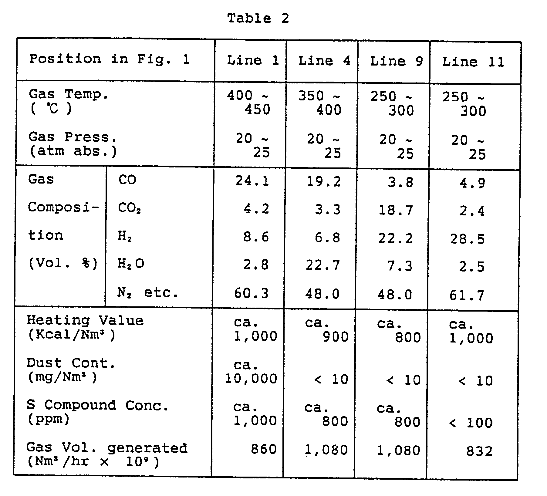
- From the data of Table 2, it is seen that the values for the content of CO, CO₂, dust and sulfur compounds had been decreased markedly, while the content of H₂O was decreased a little and the content of H₂ had been increased remarkably.
- It should be noted, that the high temperature reducing gases to be treated according to the present invention are not restricted only to the furnace gas from a coal gasification furnace but are inclusive of every high temperature reducing gas containing CO and sulfur compounds.
-
- This Example describes an embodiment of the third aspect of the present invention exemplified by the schematic flow diagram of Fig. 2. Here, the same element or constituent part as shown in Fig. 4 is designated with the same numeral symbol as in Fig. 4 and explanation therefor is omitted.
- As shown in Fig. 2, the gas generated in a coal gasification furnace 21 (especially that of compressed air burning) is supplied to a
gas purifier 23 and is purified here before it is introduced into aCO-shift reactor 36. Into the furnace gas is injected a steam from, for example, a middle or low pressure steam extraction of turbine. ACO₂ separator 37 is disposed downstream of theCO-shift reactor 36. - The gas exhausted from the exit of the
gas purifier 23 is a combustible gas composed mainly of CO, H₂ and N₂ (See Table 3, column for the position B), of which composition in the case of air-burning is typically about 25 % of CO and about 10 % of H₂. - This gas is moistened by injecting thereinto a steam from a turbine steam extraction and the thus moistened gas is supplied to a
CO-shift reactor 36, where CO is converted into CO₂ through a reaction with water by the following reaction scheme:
- The shift reaction of CO into CO₂ is an exothermic raction, so that the reaction will be facilitated if the temperature of reaction mixture is lower as deduced from the equillibrium therefor. In the practice however, the reaction may be conducted advantageously at a temperature of about 300 - 500°C .
- In the above reaction equation, the heat balance between the original system side and the product system side is almost unchanged, because only the CO content is replaced by the corresponding amount of H₂ after the reaction. In view of the practical operation of fuel combustion, it may be advantageous for the stability of combustion to employ H₂ as the combustible fuel component as compared with the use of CO as the combustible fuel component.
- The gas exhausted from the
CO-shift reactor 36 is a combustible gas composed mainly of H₂, CO₂ and N₂ with some CO and H₂O (See Table 3, column for the position C). This gas is supplied to aCO₂ separator 27, wherein CO₂ is removed from the main stream of the product gas to be fed to thegas turbine 25, while recovering CO₂ from the CO₂ separator by means of a suitable CO₂ recovery unit. Thus, the fuel gas for the gas turbine consists now mainly of hydrogen and nitrogen in the case of air-burning and essentially of only hydrogen in the case of oxygen-burning. Therefore, any formation of CO₂ upon operation of a gas turbine is steeply decreased as seen from Table 3, column for the position D of Fig. 2, besides the stability of combustion in the gas turbine burner to be attained as explained above. - For the
CO₂ separator 37, there may be employed advantageously those operable on a physical principle on the basis of PSA technique. - The CO₂ separated from the main stream of the gas is present in a compressed condition, so that it may be possible to recover therefrom a further energy by employing, for example, a
gas expander 38 to attain supplemental power generation. There may be cases requiring no relieving of pressure up to nearly the atmospheric pressure due to the condition of recovery of CO₂, such as in the case of recovery as solid (dry ice) or as liquid or in the case of recovery as the raw material for chemical industry, such as methanol synthesis etc. - The employment of
CO₂ separator 37 based on PSA technique permits to remove residual sulfur compounds, such as H₂S, COS etc., which have not been removed in the dry desulfurization unit in thegas purifier 23 and are in a concentration of about 30 - 100 ppm, leaving a clean product gas (position D of Fig. 2) which is clean enough to be allowed to use even for a fuel cell. The sulfur compounds desorbed from theCO₂ separator 37 are collected in asulfur compound separator 39 and are separated from CO₂. The desorbed CO₂ free from sulfur compounds is recovered in a highly pure state after it has passed agas expander 38. The sulfur compounds collected by thesulfur compound separator 39 are returned to thegas purifier 23. A recovery of the heat of reaction in the CO-shift reactor can be attained by installingheat recovery boilers 
Claims (3)
- A process for purifying high temperature reducing gases by removing sulfur compounds contained in such reducing gases by dry adsorption on adsorbent, comprising subjecting the high temperature reducing gas to a catalytic CO-shift reaction in a reactor having a corresponding catalyst and equipped with a heat recovery means for controlling the reaction gas temperature while injecting steam into said high temperature reducing gas, in order to convert the content of CO in the high temperature reducing gas into CO₂, effecting the removal of the sulfur compounds and of CO₂ by dry adsorption of them on adsorbent under control of the temperature of the gas by means of the heat recovery means of the reactor and separating the sulfur compounds from CO₂ to recover them.
- A process for purifying high temperature reducing gases as claimed in Claim 1, wherein the sulfur compounds separated from CO₂ are supplied to a Claus process sulfur recovery unit, where H₂S in the sulfur compounds is converted into elementary sulfur which is separated and recovered, and the exhaust gas from this recovery unit is subjected to reduction by the hydrogen of the product gas to convert the other sulfur compounds and the residual elementary sulfur into H₂S, whereupon the so formed H₂S is separated and returned to the Claus process sulfur recovery unit.
- A composite power plant with coal gasification having a coal gasification furnace, a gas purifier for effecting removal of impurities from the furnace gas produced in the gasification furnace, a gas turbine power generation unit having a burner for burning the purified product gas, a waste heat boiler for generating steam by recovering the sensible heat of the gas turbine exhaust gas and a steam turbine power generation unit operated by the steam from the waste heat boiler, comprising a CO-shift reactor for converting CO in the purified product gas into CO₂ disposed between the gas purifier and the burner of the gas turbine power generation unit, a means for removing CO₂ and sulfur compounds from the product gas in dry system and a sulfur compound separator separating sulfur compounds from CO₂.
Priority Applications (1)
| Application Number | Priority Date | Filing Date | Title |
|---|---|---|---|
| AT91400307T ATE93262T1 (en) | 1990-02-09 | 1991-02-08 | METHOD FOR CLEANING HOT REDUCTION GASES AND COMBINED POWER PLANT WITH COAL GASIFICATION. |
Applications Claiming Priority (4)
| Application Number | Priority Date | Filing Date | Title |
|---|---|---|---|
| JP31184/90 | 1990-02-09 | ||
| JP2031184A JP2870929B2 (en) | 1990-02-09 | 1990-02-09 | Integrated coal gasification combined cycle power plant |
| JP2041114A JPH07114927B2 (en) | 1990-02-23 | 1990-02-23 | ▲ High ▼ Refining method of warm reducing gas |
| JP41114/90 | 1990-02-23 |
Publications (2)
| Publication Number | Publication Date |
|---|---|
| EP0444987A1 true EP0444987A1 (en) | 1991-09-04 |
| EP0444987B1 EP0444987B1 (en) | 1993-08-18 |
Family
ID=26369632
Family Applications (1)
| Application Number | Title | Priority Date | Filing Date |
|---|---|---|---|
| EP91400307A Expired - Lifetime EP0444987B1 (en) | 1990-02-09 | 1991-02-08 | Process for purifying high-temperature reducing gases and composite power plant with coal gasification |
Country Status (5)
| Country | Link |
|---|---|
| EP (1) | EP0444987B1 (en) |
| CN (1) | CN1033427C (en) |
| AU (1) | AU638543B2 (en) |
| CA (1) | CA2036052C (en) |
| DE (1) | DE69100271T2 (en) |
Cited By (10)
| Publication number | Priority date | Publication date | Assignee | Title |
|---|---|---|---|---|
| US6596248B2 (en) | 2000-03-31 | 2003-07-22 | Alstom (Switzerland) Ltd | Method for removing carbon dioxide from exhaust gas |
| US7354562B2 (en) | 2002-10-25 | 2008-04-08 | Air Products And Chemicals, Inc. | Simultaneous shift-reactive and adsorptive process to produce hydrogen |
| US8206669B2 (en) | 2010-07-27 | 2012-06-26 | Air Products And Chemicals, Inc. | Method and apparatus for treating a sour gas |
| US8268044B2 (en) | 2010-07-13 | 2012-09-18 | Air Products And Chemicals, Inc. | Separation of a sour syngas stream |
| US8518356B2 (en) | 2010-07-27 | 2013-08-27 | Air Products And Chemicals, Inc. | Method and apparatus for adjustably treating a sour gas |
| US9261020B2 (en) | 2010-03-29 | 2016-02-16 | Mitsubishi Heavy Industries, Ltd. | Integrated coal gasification combined cycle plant |
| EP2634141A4 (en) * | 2010-10-05 | 2016-04-13 | Hitachi Ltd | CO2 SEPARATION AND RECOVERY EQUIPMENT AND ELECTRIC POWER PLANT COMBINED WITH CHARCOAL GASIFICATION COMPRISING SAID CO 2 SEPARATION AND RECOVERY EQUIPMENT |
| CN112646614A (en) * | 2020-11-30 | 2021-04-13 | 中国科学院过程工程研究所 | Moving bed type blast furnace gas desulfurization device and desulfurization method thereof |
| WO2024076612A1 (en) * | 2022-10-06 | 2024-04-11 | Air Products And Chemicals, Inc. | Process and system for water-gas shift conversion of synthesis gas with high co concentration |
| CN119680479A (en) * | 2024-11-25 | 2025-03-25 | 国家能源集团宁夏煤业有限责任公司 | Sulfur recovery unit |
Families Citing this family (6)
| Publication number | Priority date | Publication date | Assignee | Title |
|---|---|---|---|---|
| CN1116501C (en) * | 1998-07-13 | 2003-07-30 | 诺尔斯海德公司 | Processes for the production of electricity, steam and carbon dioxide from hydrocarbon feedstocks |
| AT508523B1 (en) | 2009-07-31 | 2011-04-15 | Siemens Vai Metals Tech Gmbh | REFORM GAS-BASED REDUCTION PROCESS AND DEVICE WITH DECARBONIZING THE COMBUSTION GAS FOR THE REFORMER |
| CN102559269B (en) * | 2010-08-20 | 2015-03-04 | 新奥科技发展有限公司 | Method for combining coal gasification process and vapor turbine power generation process |
| CN107774114B (en) * | 2017-10-25 | 2021-07-16 | 昆明理工大学 | A kind of method that utilizes phosphogypsum decomposition slag to capture carbon dioxide |
| CN112403224B (en) * | 2019-11-06 | 2022-01-25 | 中冶长天国际工程有限责任公司 | CO oxidation and denitration system and method |
| JP7251858B2 (en) | 2022-10-07 | 2023-04-04 | 廣存 高橋 | Bio-multistage hydrogen generation system |
Citations (4)
| Publication number | Priority date | Publication date | Assignee | Title |
|---|---|---|---|---|
| GB992161A (en) * | 1963-04-05 | 1965-05-19 | Exxon Research Engineering Co | Improvements in hydrocarbon gasification processes |
| FR2101724A5 (en) * | 1970-07-17 | 1972-03-31 | Shell Int Research | |
| US4572829A (en) * | 1984-11-09 | 1986-02-25 | Union Carbide Corporation | Ammonia synthesis gas purification |
| EP0311932A1 (en) * | 1987-10-16 | 1989-04-19 | Air Products And Chemicals, Inc. | Recovery of nitrogen, hydrogen and carbon dioxide from hydrocarbon reformate |
Family Cites Families (3)
| Publication number | Priority date | Publication date | Assignee | Title |
|---|---|---|---|---|
| DE3228481A1 (en) * | 1982-07-30 | 1984-02-02 | VEG-Gasinstituut N.V., 7300 Apeldoorn | REACTION MEASURES, METHOD FOR THEIR PRODUCTION AND THEIR USE |
| US4725381A (en) * | 1984-03-02 | 1988-02-16 | Imperial Chemical Industries Plc | Hydrogen streams |
| US4696680A (en) * | 1985-10-03 | 1987-09-29 | The United States Of America As Represented By The United States Department Of Energy | Method and apparatus for the selective separation of gaseous coal gasification products by pressure swing adsorption |
-
1991
- 1991-02-07 AU AU70810/91A patent/AU638543B2/en not_active Expired
- 1991-02-08 CN CN91100960A patent/CN1033427C/en not_active Expired - Lifetime
- 1991-02-08 CA CA002036052A patent/CA2036052C/en not_active Expired - Fee Related
- 1991-02-08 DE DE91400307T patent/DE69100271T2/en not_active Expired - Lifetime
- 1991-02-08 EP EP91400307A patent/EP0444987B1/en not_active Expired - Lifetime
Patent Citations (4)
| Publication number | Priority date | Publication date | Assignee | Title |
|---|---|---|---|---|
| GB992161A (en) * | 1963-04-05 | 1965-05-19 | Exxon Research Engineering Co | Improvements in hydrocarbon gasification processes |
| FR2101724A5 (en) * | 1970-07-17 | 1972-03-31 | Shell Int Research | |
| US4572829A (en) * | 1984-11-09 | 1986-02-25 | Union Carbide Corporation | Ammonia synthesis gas purification |
| EP0311932A1 (en) * | 1987-10-16 | 1989-04-19 | Air Products And Chemicals, Inc. | Recovery of nitrogen, hydrogen and carbon dioxide from hydrocarbon reformate |
Cited By (13)
| Publication number | Priority date | Publication date | Assignee | Title |
|---|---|---|---|---|
| US6596248B2 (en) | 2000-03-31 | 2003-07-22 | Alstom (Switzerland) Ltd | Method for removing carbon dioxide from exhaust gas |
| US7022168B2 (en) | 2000-03-31 | 2006-04-04 | Alstom Technology Ltd | Device for removing carbon dioxide from exhaust gas |
| US7354562B2 (en) | 2002-10-25 | 2008-04-08 | Air Products And Chemicals, Inc. | Simultaneous shift-reactive and adsorptive process to produce hydrogen |
| US9261020B2 (en) | 2010-03-29 | 2016-02-16 | Mitsubishi Heavy Industries, Ltd. | Integrated coal gasification combined cycle plant |
| US8268044B2 (en) | 2010-07-13 | 2012-09-18 | Air Products And Chemicals, Inc. | Separation of a sour syngas stream |
| US9090839B2 (en) | 2010-07-27 | 2015-07-28 | Air Products And Chemicals, Inc. | Method and apparatus for adjustably treating a sour gas |
| US8518356B2 (en) | 2010-07-27 | 2013-08-27 | Air Products And Chemicals, Inc. | Method and apparatus for adjustably treating a sour gas |
| US8206669B2 (en) | 2010-07-27 | 2012-06-26 | Air Products And Chemicals, Inc. | Method and apparatus for treating a sour gas |
| EP2634141A4 (en) * | 2010-10-05 | 2016-04-13 | Hitachi Ltd | CO2 SEPARATION AND RECOVERY EQUIPMENT AND ELECTRIC POWER PLANT COMBINED WITH CHARCOAL GASIFICATION COMPRISING SAID CO 2 SEPARATION AND RECOVERY EQUIPMENT |
| US9427703B2 (en) | 2010-10-05 | 2016-08-30 | Hitachi, Ltd. | CO2 separation and recovery equipment, and a coal gasification combined power plant comprising CO2 separation and recovery equipment |
| CN112646614A (en) * | 2020-11-30 | 2021-04-13 | 中国科学院过程工程研究所 | Moving bed type blast furnace gas desulfurization device and desulfurization method thereof |
| WO2024076612A1 (en) * | 2022-10-06 | 2024-04-11 | Air Products And Chemicals, Inc. | Process and system for water-gas shift conversion of synthesis gas with high co concentration |
| CN119680479A (en) * | 2024-11-25 | 2025-03-25 | 国家能源集团宁夏煤业有限责任公司 | Sulfur recovery unit |
Also Published As
| Publication number | Publication date |
|---|---|
| AU638543B2 (en) | 1993-07-01 |
| AU7081091A (en) | 1991-09-19 |
| EP0444987B1 (en) | 1993-08-18 |
| CA2036052C (en) | 1997-02-11 |
| DE69100271D1 (en) | 1993-09-23 |
| CA2036052A1 (en) | 1991-08-10 |
| CN1053898A (en) | 1991-08-21 |
| DE69100271T2 (en) | 1994-01-27 |
| CN1033427C (en) | 1996-12-04 |
Similar Documents
| Publication | Publication Date | Title |
|---|---|---|
| JP4317213B2 (en) | Carbon capture arrangement and method | |
| EP0444987B1 (en) | Process for purifying high-temperature reducing gases and composite power plant with coal gasification | |
| US4833877A (en) | Process for the reduction of pollutant emissions from power stations with combined gas/steam turbine processes with preceding coal gasification | |
| KR930012039B1 (en) | Method of producing carbon dioxide from combustion exhaust while recovering nitrogen and argon by-products | |
| US6090356A (en) | Removal of acidic gases in a gasification power system with production of hydrogen | |
| US5440873A (en) | Gasification-combined power plant | |
| US7374742B2 (en) | Direct sulfur recovery system | |
| JP2012522090A (en) | Method for producing purified synthesis gas | |
| US7935324B2 (en) | Integrated warm gas desulfurization and gas shift for cleanup of gaseous streams | |
| KR100278949B1 (en) | Systems and methods for removing sulfur species from hot gases from coal | |
| JPH04244504A (en) | Carbon dioxide recovery type coal thermal power system | |
| TW533265B (en) | Using shifted syngas to regenerate SCR type catalyst | |
| US3720625A (en) | Process for preparing hydrogen or nitrogen and hydrogen under pressure | |
| US11554954B2 (en) | Process for producing a synthesis gas | |
| JP2870929B2 (en) | Integrated coal gasification combined cycle power plant | |
| JPH10235128A (en) | Dry desulfurization apparatus and power plant using the same | |
| JP2635652B2 (en) | Dry desulfurization of coal gas | |
| EP0375048B1 (en) | Method and device for desulphurising gas | |
| JP3700073B2 (en) | Method and apparatus for burning hydrogen sulfide-containing gas | |
| JPH07114927B2 (en) | ▲ High ▼ Refining method of warm reducing gas | |
| JPH06293888A (en) | Method for recovering sulfur from plant for gasifying coal and device therefor | |
| JPH02308894A (en) | Partial oxidation method of carbonaceous fuel | |
| JPH0360416A (en) | Partial oxidation method of carbonaceous fuel | |
| JP2004189993A (en) | Method for refining gas, gas refiner and coal gasification power generation system using the same | |
| JPH11293261A (en) | Power generation method and power generation device using at least garbage as raw material according to power consumption status |
Legal Events
| Date | Code | Title | Description |
|---|---|---|---|
| PUAI | Public reference made under article 153(3) epc to a published international application that has entered the european phase |
Free format text: ORIGINAL CODE: 0009012 |
|
| AK | Designated contracting states |
Kind code of ref document: A1 Designated state(s): AT BE DE FR GB IT NL SE |
|
| 17P | Request for examination filed |
Effective date: 19920130 |
|
| 17Q | First examination report despatched |
Effective date: 19921028 |
|
| GRAA | (expected) grant |
Free format text: ORIGINAL CODE: 0009210 |
|
| AK | Designated contracting states |
Kind code of ref document: B1 Designated state(s): AT BE DE FR GB IT NL SE |
|
| REF | Corresponds to: |
Ref document number: 93262 Country of ref document: AT Date of ref document: 19930915 Kind code of ref document: T |
|
| ET | Fr: translation filed | ||
| REF | Corresponds to: |
Ref document number: 69100271 Country of ref document: DE Date of ref document: 19930923 |
|
| ITF | It: translation for a ep patent filed | ||
| PLBE | No opposition filed within time limit |
Free format text: ORIGINAL CODE: 0009261 |
|
| STAA | Information on the status of an ep patent application or granted ep patent |
Free format text: STATUS: NO OPPOSITION FILED WITHIN TIME LIMIT |
|
| 26N | No opposition filed | ||
| EAL | Se: european patent in force in sweden |
Ref document number: 91400307.4 |
|
| PGFP | Annual fee paid to national office [announced via postgrant information from national office to epo] |
Ref country code: SE Payment date: 19990204 Year of fee payment: 9 |
|
| PGFP | Annual fee paid to national office [announced via postgrant information from national office to epo] |
Ref country code: FR Payment date: 19990209 Year of fee payment: 9 |
|
| PGFP | Annual fee paid to national office [announced via postgrant information from national office to epo] |
Ref country code: AT Payment date: 19990211 Year of fee payment: 9 Ref country code: GB Payment date: 19990211 Year of fee payment: 9 |
|
| PGFP | Annual fee paid to national office [announced via postgrant information from national office to epo] |
Ref country code: NL Payment date: 19990224 Year of fee payment: 9 |
|
| PGFP | Annual fee paid to national office [announced via postgrant information from national office to epo] |
Ref country code: BE Payment date: 19990416 Year of fee payment: 9 |
|
| PG25 | Lapsed in a contracting state [announced via postgrant information from national office to epo] |
Ref country code: GB Free format text: LAPSE BECAUSE OF NON-PAYMENT OF DUE FEES Effective date: 20000208 Ref country code: AT Free format text: LAPSE BECAUSE OF NON-PAYMENT OF DUE FEES Effective date: 20000208 |
|
| PG25 | Lapsed in a contracting state [announced via postgrant information from national office to epo] |
Ref country code: SE Free format text: LAPSE BECAUSE OF NON-PAYMENT OF DUE FEES Effective date: 20000209 |
|
| PG25 | Lapsed in a contracting state [announced via postgrant information from national office to epo] |
Ref country code: BE Free format text: LAPSE BECAUSE OF NON-PAYMENT OF DUE FEES Effective date: 20000228 |
|
| BERE | Be: lapsed |
Owner name: MITSUBISHI JUKOGYO K.K. Effective date: 20000228 |
|
| PG25 | Lapsed in a contracting state [announced via postgrant information from national office to epo] |
Ref country code: NL Free format text: LAPSE BECAUSE OF NON-PAYMENT OF DUE FEES Effective date: 20000901 |
|
| GBPC | Gb: european patent ceased through non-payment of renewal fee |
Effective date: 20000208 |
|
| EUG | Se: european patent has lapsed |
Ref document number: 91400307.4 |
|
| PG25 | Lapsed in a contracting state [announced via postgrant information from national office to epo] |
Ref country code: FR Free format text: LAPSE BECAUSE OF NON-PAYMENT OF DUE FEES Effective date: 20001031 |
|
| NLV4 | Nl: lapsed or anulled due to non-payment of the annual fee |
Effective date: 20000901 |
|
| REG | Reference to a national code |
Ref country code: FR Ref legal event code: ST |
|
| PGFP | Annual fee paid to national office [announced via postgrant information from national office to epo] |
Ref country code: IT Payment date: 20100220 Year of fee payment: 20 |
|
| PGFP | Annual fee paid to national office [announced via postgrant information from national office to epo] |
Ref country code: DE Payment date: 20100219 Year of fee payment: 20 |
|
| REG | Reference to a national code |
Ref country code: DE Ref legal event code: R071 Ref document number: 69100271 Country of ref document: DE |
|
| PG25 | Lapsed in a contracting state [announced via postgrant information from national office to epo] |
Ref country code: DE Free format text: LAPSE BECAUSE OF EXPIRATION OF PROTECTION Effective date: 20110208 |