EP0441522A2 - Control device for an automobile - Google Patents
Control device for an automobile Download PDFInfo
- Publication number
- EP0441522A2 EP0441522A2 EP91300704A EP91300704A EP0441522A2 EP 0441522 A2 EP0441522 A2 EP 0441522A2 EP 91300704 A EP91300704 A EP 91300704A EP 91300704 A EP91300704 A EP 91300704A EP 0441522 A2 EP0441522 A2 EP 0441522A2
- Authority
- EP
- European Patent Office
- Prior art keywords
- neural
- neural elements
- output
- signals
- control device
- Prior art date
- Legal status (The legal status is an assumption and is not a legal conclusion. Google has not performed a legal analysis and makes no representation as to the accuracy of the status listed.)
- Granted
Links
Images


Classifications
-
- G—PHYSICS
- G01—MEASURING; TESTING
- G01S—RADIO DIRECTION-FINDING; RADIO NAVIGATION; DETERMINING DISTANCE OR VELOCITY BY USE OF RADIO WAVES; LOCATING OR PRESENCE-DETECTING BY USE OF THE REFLECTION OR RERADIATION OF RADIO WAVES; ANALOGOUS ARRANGEMENTS USING OTHER WAVES
- G01S17/00—Systems using the reflection or reradiation of electromagnetic waves other than radio waves, e.g. lidar systems
- G01S17/88—Lidar systems specially adapted for specific applications
- G01S17/93—Lidar systems specially adapted for specific applications for anti-collision purposes
- G01S17/931—Lidar systems specially adapted for specific applications for anti-collision purposes of land vehicles
-
- B—PERFORMING OPERATIONS; TRANSPORTING
- B60—VEHICLES IN GENERAL
- B60K—ARRANGEMENT OR MOUNTING OF PROPULSION UNITS OR OF TRANSMISSIONS IN VEHICLES; ARRANGEMENT OR MOUNTING OF PLURAL DIVERSE PRIME-MOVERS IN VEHICLES; AUXILIARY DRIVES FOR VEHICLES; INSTRUMENTATION OR DASHBOARDS FOR VEHICLES; ARRANGEMENTS IN CONNECTION WITH COOLING, AIR INTAKE, GAS EXHAUST OR FUEL SUPPLY OF PROPULSION UNITS IN VEHICLES
- B60K31/00—Vehicle fittings, acting on a single sub-unit only, for automatically controlling vehicle speed, i.e. preventing speed from exceeding an arbitrarily established velocity or maintaining speed at a particular velocity, as selected by the vehicle operator
- B60K31/0008—Vehicle fittings, acting on a single sub-unit only, for automatically controlling vehicle speed, i.e. preventing speed from exceeding an arbitrarily established velocity or maintaining speed at a particular velocity, as selected by the vehicle operator including means for detecting potential obstacles in vehicle path
-
- B—PERFORMING OPERATIONS; TRANSPORTING
- B60—VEHICLES IN GENERAL
- B60W—CONJOINT CONTROL OF VEHICLE SUB-UNITS OF DIFFERENT TYPE OR DIFFERENT FUNCTION; CONTROL SYSTEMS SPECIALLY ADAPTED FOR HYBRID VEHICLES; ROAD VEHICLE DRIVE CONTROL SYSTEMS FOR PURPOSES NOT RELATED TO THE CONTROL OF A PARTICULAR SUB-UNIT
- B60W30/00—Purposes of road vehicle drive control systems not related to the control of a particular sub-unit, e.g. of systems using conjoint control of vehicle sub-units
- B60W30/18—Propelling the vehicle
- B60W30/20—Reducing vibrations in the driveline
-
- B—PERFORMING OPERATIONS; TRANSPORTING
- B60—VEHICLES IN GENERAL
- B60W—CONJOINT CONTROL OF VEHICLE SUB-UNITS OF DIFFERENT TYPE OR DIFFERENT FUNCTION; CONTROL SYSTEMS SPECIALLY ADAPTED FOR HYBRID VEHICLES; ROAD VEHICLE DRIVE CONTROL SYSTEMS FOR PURPOSES NOT RELATED TO THE CONTROL OF A PARTICULAR SUB-UNIT
- B60W40/00—Estimation or calculation of non-directly measurable driving parameters for road vehicle drive control systems not related to the control of a particular sub unit, e.g. by using mathematical models
- B60W40/08—Estimation or calculation of non-directly measurable driving parameters for road vehicle drive control systems not related to the control of a particular sub unit, e.g. by using mathematical models related to drivers or passengers
- B60W40/09—Driving style or behaviour
-
- B—PERFORMING OPERATIONS; TRANSPORTING
- B60—VEHICLES IN GENERAL
- B60W—CONJOINT CONTROL OF VEHICLE SUB-UNITS OF DIFFERENT TYPE OR DIFFERENT FUNCTION; CONTROL SYSTEMS SPECIALLY ADAPTED FOR HYBRID VEHICLES; ROAD VEHICLE DRIVE CONTROL SYSTEMS FOR PURPOSES NOT RELATED TO THE CONTROL OF A PARTICULAR SUB-UNIT
- B60W50/00—Details of control systems for road vehicle drive control not related to the control of a particular sub-unit, e.g. process diagnostic or vehicle driver interfaces
-
- F—MECHANICAL ENGINEERING; LIGHTING; HEATING; WEAPONS; BLASTING
- F02—COMBUSTION ENGINES; HOT-GAS OR COMBUSTION-PRODUCT ENGINE PLANTS
- F02D—CONTROLLING COMBUSTION ENGINES
- F02D41/00—Electrical control of supply of combustible mixture or its constituents
- F02D41/02—Circuit arrangements for generating control signals
- F02D41/14—Introducing closed-loop corrections
- F02D41/1401—Introducing closed-loop corrections characterised by the control or regulation method
- F02D41/1405—Neural network control
-
- F—MECHANICAL ENGINEERING; LIGHTING; HEATING; WEAPONS; BLASTING
- F02—COMBUSTION ENGINES; HOT-GAS OR COMBUSTION-PRODUCT ENGINE PLANTS
- F02P—IGNITION, OTHER THAN COMPRESSION IGNITION, FOR INTERNAL-COMBUSTION ENGINES; TESTING OF IGNITION TIMING IN COMPRESSION-IGNITION ENGINES
- F02P5/00—Advancing or retarding ignition; Control therefor
- F02P5/04—Advancing or retarding ignition; Control therefor automatically, as a function of the working conditions of the engine or vehicle or of the atmospheric conditions
- F02P5/045—Advancing or retarding ignition; Control therefor automatically, as a function of the working conditions of the engine or vehicle or of the atmospheric conditions combined with electronic control of other engine functions, e.g. fuel injection
-
- G—PHYSICS
- G01—MEASURING; TESTING
- G01L—MEASURING FORCE, STRESS, TORQUE, WORK, MECHANICAL POWER, MECHANICAL EFFICIENCY, OR FLUID PRESSURE
- G01L23/00—Devices or apparatus for measuring or indicating or recording rapid changes, such as oscillations, in the pressure of steam, gas, or liquid; Indicators for determining work or energy of steam, internal-combustion, or other fluid-pressure engines from the condition of the working fluid
- G01L23/22—Devices or apparatus for measuring or indicating or recording rapid changes, such as oscillations, in the pressure of steam, gas, or liquid; Indicators for determining work or energy of steam, internal-combustion, or other fluid-pressure engines from the condition of the working fluid for detecting or indicating knocks in internal-combustion engines; Units comprising pressure-sensitive members combined with ignitors for firing internal-combustion engines
- G01L23/221—Devices or apparatus for measuring or indicating or recording rapid changes, such as oscillations, in the pressure of steam, gas, or liquid; Indicators for determining work or energy of steam, internal-combustion, or other fluid-pressure engines from the condition of the working fluid for detecting or indicating knocks in internal-combustion engines; Units comprising pressure-sensitive members combined with ignitors for firing internal-combustion engines for detecting or indicating knocks in internal combustion engines
- G01L23/225—Devices or apparatus for measuring or indicating or recording rapid changes, such as oscillations, in the pressure of steam, gas, or liquid; Indicators for determining work or energy of steam, internal-combustion, or other fluid-pressure engines from the condition of the working fluid for detecting or indicating knocks in internal-combustion engines; Units comprising pressure-sensitive members combined with ignitors for firing internal-combustion engines for detecting or indicating knocks in internal combustion engines circuit arrangements therefor
-
- B—PERFORMING OPERATIONS; TRANSPORTING
- B60—VEHICLES IN GENERAL
- B60W—CONJOINT CONTROL OF VEHICLE SUB-UNITS OF DIFFERENT TYPE OR DIFFERENT FUNCTION; CONTROL SYSTEMS SPECIALLY ADAPTED FOR HYBRID VEHICLES; ROAD VEHICLE DRIVE CONTROL SYSTEMS FOR PURPOSES NOT RELATED TO THE CONTROL OF A PARTICULAR SUB-UNIT
- B60W30/00—Purposes of road vehicle drive control systems not related to the control of a particular sub-unit, e.g. of systems using conjoint control of vehicle sub-units
- B60W30/18—Propelling the vehicle
- B60W30/20—Reducing vibrations in the driveline
- B60W2030/206—Reducing vibrations in the driveline related or induced by the engine
-
- B—PERFORMING OPERATIONS; TRANSPORTING
- B60—VEHICLES IN GENERAL
- B60W—CONJOINT CONTROL OF VEHICLE SUB-UNITS OF DIFFERENT TYPE OR DIFFERENT FUNCTION; CONTROL SYSTEMS SPECIALLY ADAPTED FOR HYBRID VEHICLES; ROAD VEHICLE DRIVE CONTROL SYSTEMS FOR PURPOSES NOT RELATED TO THE CONTROL OF A PARTICULAR SUB-UNIT
- B60W50/00—Details of control systems for road vehicle drive control not related to the control of a particular sub-unit, e.g. process diagnostic or vehicle driver interfaces
- B60W2050/0001—Details of the control system
- B60W2050/0002—Automatic control, details of type of controller or control system architecture
-
- B—PERFORMING OPERATIONS; TRANSPORTING
- B60—VEHICLES IN GENERAL
- B60W—CONJOINT CONTROL OF VEHICLE SUB-UNITS OF DIFFERENT TYPE OR DIFFERENT FUNCTION; CONTROL SYSTEMS SPECIALLY ADAPTED FOR HYBRID VEHICLES; ROAD VEHICLE DRIVE CONTROL SYSTEMS FOR PURPOSES NOT RELATED TO THE CONTROL OF A PARTICULAR SUB-UNIT
- B60W50/00—Details of control systems for road vehicle drive control not related to the control of a particular sub-unit, e.g. process diagnostic or vehicle driver interfaces
- B60W2050/0001—Details of the control system
- B60W2050/0043—Signal treatments, identification of variables or parameters, parameter estimation or state estimation
- B60W2050/0057—Frequency analysis, spectral techniques or transforms
-
- B—PERFORMING OPERATIONS; TRANSPORTING
- B60—VEHICLES IN GENERAL
- B60W—CONJOINT CONTROL OF VEHICLE SUB-UNITS OF DIFFERENT TYPE OR DIFFERENT FUNCTION; CONTROL SYSTEMS SPECIALLY ADAPTED FOR HYBRID VEHICLES; ROAD VEHICLE DRIVE CONTROL SYSTEMS FOR PURPOSES NOT RELATED TO THE CONTROL OF A PARTICULAR SUB-UNIT
- B60W2540/00—Input parameters relating to occupants
- B60W2540/30—Driving style
-
- F—MECHANICAL ENGINEERING; LIGHTING; HEATING; WEAPONS; BLASTING
- F02—COMBUSTION ENGINES; HOT-GAS OR COMBUSTION-PRODUCT ENGINE PLANTS
- F02B—INTERNAL-COMBUSTION PISTON ENGINES; COMBUSTION ENGINES IN GENERAL
- F02B75/00—Other engines
- F02B75/02—Engines characterised by their cycles, e.g. six-stroke
- F02B2075/022—Engines characterised by their cycles, e.g. six-stroke having less than six strokes per cycle
- F02B2075/027—Engines characterised by their cycles, e.g. six-stroke having less than six strokes per cycle four
-
- F—MECHANICAL ENGINEERING; LIGHTING; HEATING; WEAPONS; BLASTING
- F02—COMBUSTION ENGINES; HOT-GAS OR COMBUSTION-PRODUCT ENGINE PLANTS
- F02D—CONTROLLING COMBUSTION ENGINES
- F02D41/00—Electrical control of supply of combustible mixture or its constituents
- F02D41/02—Circuit arrangements for generating control signals
- F02D41/14—Introducing closed-loop corrections
- F02D41/1401—Introducing closed-loop corrections characterised by the control or regulation method
- F02D2041/1433—Introducing closed-loop corrections characterised by the control or regulation method using a model or simulation of the system
-
- F—MECHANICAL ENGINEERING; LIGHTING; HEATING; WEAPONS; BLASTING
- F16—ENGINEERING ELEMENTS AND UNITS; GENERAL MEASURES FOR PRODUCING AND MAINTAINING EFFECTIVE FUNCTIONING OF MACHINES OR INSTALLATIONS; THERMAL INSULATION IN GENERAL
- F16H—GEARING
- F16H61/00—Control functions within control units of change-speed- or reversing-gearings for conveying rotary motion ; Control of exclusively fluid gearing, friction gearing, gearings with endless flexible members or other particular types of gearing
- F16H2061/0075—Control functions within control units of change-speed- or reversing-gearings for conveying rotary motion ; Control of exclusively fluid gearing, friction gearing, gearings with endless flexible members or other particular types of gearing characterised by a particular control method
- F16H2061/0081—Fuzzy logic
-
- F—MECHANICAL ENGINEERING; LIGHTING; HEATING; WEAPONS; BLASTING
- F16—ENGINEERING ELEMENTS AND UNITS; GENERAL MEASURES FOR PRODUCING AND MAINTAINING EFFECTIVE FUNCTIONING OF MACHINES OR INSTALLATIONS; THERMAL INSULATION IN GENERAL
- F16H—GEARING
- F16H61/00—Control functions within control units of change-speed- or reversing-gearings for conveying rotary motion ; Control of exclusively fluid gearing, friction gearing, gearings with endless flexible members or other particular types of gearing
- F16H2061/0075—Control functions within control units of change-speed- or reversing-gearings for conveying rotary motion ; Control of exclusively fluid gearing, friction gearing, gearings with endless flexible members or other particular types of gearing characterised by a particular control method
- F16H2061/0084—Neural networks
-
- F—MECHANICAL ENGINEERING; LIGHTING; HEATING; WEAPONS; BLASTING
- F16—ENGINEERING ELEMENTS AND UNITS; GENERAL MEASURES FOR PRODUCING AND MAINTAINING EFFECTIVE FUNCTIONING OF MACHINES OR INSTALLATIONS; THERMAL INSULATION IN GENERAL
- F16H—GEARING
- F16H61/00—Control functions within control units of change-speed- or reversing-gearings for conveying rotary motion ; Control of exclusively fluid gearing, friction gearing, gearings with endless flexible members or other particular types of gearing
- F16H2061/0075—Control functions within control units of change-speed- or reversing-gearings for conveying rotary motion ; Control of exclusively fluid gearing, friction gearing, gearings with endless flexible members or other particular types of gearing characterised by a particular control method
- F16H2061/0087—Adaptive control, e.g. the control parameters adapted by learning
-
- Y—GENERAL TAGGING OF NEW TECHNOLOGICAL DEVELOPMENTS; GENERAL TAGGING OF CROSS-SECTIONAL TECHNOLOGIES SPANNING OVER SEVERAL SECTIONS OF THE IPC; TECHNICAL SUBJECTS COVERED BY FORMER USPC CROSS-REFERENCE ART COLLECTIONS [XRACs] AND DIGESTS
- Y10—TECHNICAL SUBJECTS COVERED BY FORMER USPC
- Y10S—TECHNICAL SUBJECTS COVERED BY FORMER USPC CROSS-REFERENCE ART COLLECTIONS [XRACs] AND DIGESTS
- Y10S706/00—Data processing: artificial intelligence
- Y10S706/902—Application using ai with detail of the ai system
- Y10S706/903—Control
- Y10S706/905—Vehicle or aerospace
Definitions
- This invention relates to a control device for an automobile and particularly to a control device for an automobile applying neural network theory.
- a pre-programmed control device currently in use with a digital computer is typically used for fuel control in an automobile. Examples are disclosed in, inter alia , U.S. Patent No. 4,542,730 and U.S. Patent No. 4,785,783 and in these prior art devices, a number of sensors have been used for detecting operational states of the engine, transmission, brake, vehicle height, suspension and the like. In addition, the outputs from each of these sensors are each used for a particular control variable or as a correction variable for a learning control.
- An object of this invention is to provide a control device for an automobile which at least partially mitigates the above disadvantages and problems.
- An object of a feature of this invention is to provide an output signal from a sensor transformed into a plurality of signals, which are then inputted to an input layer of hierarchical neural elements, and the inputted signals therein are weighted according to weighting factors so as to generate a signal which is to be used as a parameter to determine control variables for control actuators in the automobile.
- An object of another feature of this invention is that each control actuator of the automobile is controlled based on the results of the final outputs from hierarchical neural elements, an input layer of which was inputted with the output signals from a plurality of sensors.
- a control device for an automobile having at least one sensor adapted to detect an operational state of said automobile, and an actuator for controlling said operational state
- said control device including a hierarchical group of neural elements adapted to receive an output signal from said at least one sensor, modifying means for adaptively controlling the neural elements in accordance with a desired parameter and a control means for receiving an output signal from said group of neural elements for controlling said actuator.
- the control device shown in Figure 1 is used with an automobile internal combustion engine 1 having an inlet air suction pipe 20 and an exhaust pipe 21.
- a fuel injection valve 6 is provided on a portion of the suction pipe 20 to supply fuel to the engine.
- Intake air flow is measured with an air flow sensor 22, and its measurement is inputted to a control circuit 2.
- the control circuit 2 also receives signals from a crankshaft rotation angle detector 3, an oxygen sensor 4 (and outputs from sensors of other engine parameters desired to be monitored), then supplies output signals, for example, to an ignition plug 7 via an ignition coil 5.
- a knock sensor 8 for detecting mechanical vibration of the engine caused by poor detonation due, for example, to poor fuel or incorrect ignition timing.
- the signal from the knock sensor 8 is inputted to a sample and hold circuit 11 over line 10 via a high pass filter and amplifier 9, the input signal being given in time series to the sample and hold circuit 11.
- the sample and hold circuit 11 samples the time series signals on line 10 at a given time interval and holds the signals to provide a spatial multi-variable signal consisting of 12a, 12b, 12c, ..., 12n bits in sequence of input order, so as to be inputted to the input layer of a neural computer 13.
- the output voltage on line 14 from the neural computer is output in proportion to the intensity of engine knocking, and is converted from analog to digital signals in an A/D converter of the control circuit 2, then is used to control ignition timing.
- the signal on line 15 from the control circuit 2 is used for controlling the sample and hold circuit 11.
- a control flow sequence of ignition timing ⁇ ig is shown.
- a primary or basic ignition timing ⁇ o is fetched from a memory map in control circuit 2 and is read in Step 25.
- ⁇ o is determined by the number of engine revolutions and the load (or fuel injection period, throttle valve opening angle or the like).
- an ignition timing ⁇ is calculated as where ⁇ is a calculated value for correction.
- ⁇ ig is set to start ignition.
- the intensity of knocking is measured from the output on line 14 from the neural computer 13.
- correction quantity ⁇ is calculated, wherein ⁇ is calculated in accordance with the magnitude of the output on line 14, from - ⁇ (delay angle) to + ⁇ (advance angle).
- the cylinder of an engine has a natural frequency due to engine knocking as taught by Draper as follows.
- knocking is determined by a relationship between B and C. Thereby, the knocking frequency varies according to the diameter of the cylinder bore.
- Figure 3 shows the relationship between frequencies and outputs for a different type of knock sensor 8.
- the output thereof is kept constant throughout the whole frequency range, though the magnitude of its output is very small.
- the output thereof becomes very large at a specific frequency.
- a wide-range resonant type knock sensor though an amplitude of its output is smaller than that of the resonant type knock sensor, its resonance range extends to a wider range of the frequency.
- Figure 4 shows ratios of cylinder pressures at knocking to those without knocking relative to the frequency. It is shown in Figure 4 that the pressure ratios become large at 7.9KHz, 13.8KHz, 18.5KHz, and 22KHz, thus exemplifying large pressure increases during knocking which is widely dispersed in frequency.
- a wide range resonant type knock sensor capable of detecting many knocking frequencies is preferred.
- the resonant type knock sensor may alternatively be used by setting its resonance point in accordance with the cylinder bore diamter.
- Figures 5(a) and (b) show the relationship between engine crank angle and knock sensor output.
- Figure 5(a) shows the case of a resonant type knock sensor. Knocking phenomena are caused by reciprocating pressure waves travelling inside the cylinder, which are genrated by self-detonation of mixtures due to an increase in cylinder pressure during combustion of mixtures in the cylinder. Therefore, knocking occurs delayed in time after the ignition.
- the resonant type sensor its output is generated in the range of resonant frequencies.
- Figure 5(b) shows the case of a wide range resonance type knock sensor. As shown in the Figure 5(b), the sensor output is output as a synthesized wave of many frequencies. In both cases, knocking is initiated, with ignition as the starting point, but delayed in time from ignition.
- a sampling start signal may be generated with the instant of ignition as its starting point.
- the sampling period of the sample and hold circuit 11 is advantageously set at about one tenth of the maximum measurement frequency for a wide range resonant type knock sensor. In other words, it is required to measure knock signals at predetermined intervals (preferably one tenth maximum measurement frequency) and again measure the knock signals at a next cylinder firing stroke of the cylinder of concern, the signals passing through the neural computer and then being compared to remove the effect of the noise component.
- the sampling period may be satisfactory if the minimum measurement frequency is less than the period of a minimum cycle, the sampling periods being less than the minimum measurement frequency.
- sampling is preferably taken for more than one cycle at one tenth of the resonance frequency, as stated above.
- a neural element 23 a constitutuent of a neural computer 13 is shown in Figure 6 having inputs O k ' O j and O l multiplied in the neural element with weighting factor, W ik , W ij , W il respectively, and the output O i is expressed as follows.
- ⁇ is a threshold.
- the output O i is then inputted to the next neural element.
- the neural computer has neural elements arranged in an input layer, an intermediate layer and an output layer.
- neural elements 30a, 30b and 30c receiving input signals on lines 12a, 12b and 12c respectively from the sample hold circuit 11 in sequence.
- the output from the neural element 30a is inputted to neural elements 31a, 31b and 31c in the intermediate layer, after being multiplied with respective weighting factors.
- the output signal from the neural elements 30b and 30c are inputted to the neural elements 31a, 31b and 31c in the intermediate layer, after being multiplied with respective weighting factors.
- the neural elements 31a, 31b and 31c have a threshold value ⁇ , which is subtracted from the respective outputs of the neural elements 31a, 31b, 31c, the various results are multiplied by various weighting factors and then inputted to a neural element 32 in the output layer, output from neural element 32 having a threshold value ⁇ 2 which is subtracted from the output signal of neural element 32.
- Step 33 actual knock signal data is inputted to the input layer. Then it is judged in Step 34, whether data outputted to the output layer is correct. If yes, advance is made to Step 35, wherein the weighting factor of a correct solution route is increased. Similarly, in such a situation the thresholds ⁇ 1 and ⁇ 2 may alternatively be decreased.
- Step 37 A difference from the correct solution is judged in Step 37, and when the error is below a predetermined amount, the flow sequence is completed. If the error is above the predetermined level, the sequence returns to Step 34, where weighting factors and thresholds are repeatedly readjusted until the error determined in Step 37 is acceptable.
- the number of input elements is one cycle of sensor output waveform maximum frequency divided by the sampling period.
- the configuration of these elements is shown in Figure 11.
- the input layer is composed of 30 neural elements, respective outputs thereof being inputted to the three neural elements in the intermediate layer.
- the outputs from the intermediate layer are inputted to one output layer neural element.
- FIG. 11 is one of the embodiments of the present invention, wherein detection precision may be further improved by increasing the number of neural elements in the input layer and the intermediate layer.
- Figures 12 to 14 show engineering arrangements of the neural element 23 shown in Figure 6.
- Figure 12 shows an operational amplifier having amplification factor A
- Figures 13 and 14 show a transconductance amplifier having a gain 6, and an inverter, respectively. In each case, the following explanation applies.
- Figures 15 and 16 show configurations of the coupling transistors in the input stages shown in Figures 12 and 13.
- Figure 15 is an example showing bipolar transistors
- Figure 16 is an example showing CMOS transistors.
- 16 KB, DB,KM and DM are respective constants
- I EE and I SS are output values.
- FIGs 17 to 19 there are shown block diagrams for engineeringly obtaining weighting factors for the neural element 23.
- the triode region of an FET was used where K is a constant and R is input resistance.
- a transconductance amplifier was used where R is input resistance and g m is gain, while in Figure 19 an array of 4 bit capacitors was used where c denotes capacitance and d denotes digital input.
- Figure 20 shows in block schematic form an arrangement for storing weighting factors obtained by learning.
- the weighting factors which are stored in a memory 40 of the computer in the control circuit 2 are converted to analog signals in a D/A converter 41 for driving an FET.
- Figure 21 shows another exemplary embodiment using a resonant type knock sensor 8.
- Time series signals from the knock sensor 8 are transformed into spatial multi-variable signals in the sample and hold circuit 11, the output signals from which are designated as being on lines 12a - 12f.
- These signal lines 12a - 12f are inputted to a neural computer having an input layer and an output layer having output lines 43a - 43f, wherein the numbers of neural elements in the input layer and the output layer are set to be equal.
- a sampling cycle is set to be 1/4 of the resonant frequency, and the sampling time is the same as the resonant frequency.
- the signal at line 43a is thus minus the components of the resonant frequency, and therefore consists mostly of noise components.
- Figure 22 shows respective signals in each portion at the various lines of Figure 21.
- Figure 22(a) shows input signals 12a - 12f;
- Figure 22b shows the noise signals 43c - 43f;
- Figure 22(c) shows the resonant frequency signals 44a - 44f.
- the sampling was taken at a 1/4 cycle of the resonant frequency. However, by sampling at a smaller cycle, measurement precision can be improved.
- Figure 23 is a schematic diagram of an engine control device using a neural network.
- Various object values are inputted to a neural controller 50, and the resultant output is applied to an engine 51, which is the object of control. The particular condition being controlled in the engine is then fed back to the neural controller 50.
- routines by an error feedback device 52 are for correcting a weighting factor W in the neural network of the neural controller 50, or a transformation function for neural elements.
- the error feedback routines detect differences between the objective values and the actual values representing engine state, especially when the differences are great in the manner described above in relation to Figures 9 and 10.
- the arrangement shown in Figure 23 is a system for controlling air-fuel ratio state (condition) in an engine.
- An objective value r for the air-fuel ratio of the engine is outputted by a controller 53 to the neural controller 50 and the error feedback device 52.
- various quantities of engine state such as cooling water temperature Tw, the number of engine revolutions N, engine input air flow (indicative of load) Qa and the like are also inputted to the neural controller 50.
- An open period of a fuel injection valve (time T) is outputted from the neural controller 50. Given the time T, the engine 51 outputs a resultant actual air-fuel ratio (A/F) ⁇ .
- the A/F ratio ⁇ is fed back to the neural controller 50 and to the error feedback device 52.
- the error feedback device 52 determines the error difference between the objective value r, and the actual value ⁇ . If there is a large difference of error, the configuration of the neural controller 50 is estimated to be inadequate, thus, demanding action to be taken for its reconfiguration.
- This reconfiguration can be executed through rewriting weighting factors in the neural network, or by transformation functions (Sigmoid Functions or the like), in the manner described hereinabove.
- FIG 24 the configuration of such a neural network is shown, which consists of an input layer i, an intermediate layer j and an output layer k.
- the output O j from the intermediate layer is expressed as follows.
- f is a transformation function, for instance, such as a Sigmoid function given hereinbefore.
- An output T is expressed as follows.
- Figure 25(a) shows the mode of function transformation in the intermediate layer j.
- O j (1) shows the state at the first neural element in the intermediate layer, the sum of the inputs to which neural element is The output of this function is transformed into a non-linear function to be O j (1).
- the following outputs in the intermediate layer are determined likewise to be O j (2), O j (3), ...
- the sum of the outputs from the intermediate layer becomes an input to the neural element in the output layer as shown in Figure 25(b).
- it is also transformed so as to yield an output T.
- the output T is then given to the engine 51.
- T is required to be determined as a time delay in transporting fuel during a transient state of the engine, and T may readily be given by choosing a desirable value in the functions in Figure 25(a).
- the neural controller 50 may be considered to be a model simulating the internal state of the engine 51, wherein, very complicated phenomena such as the delay in transport of fuel and the like which are hard to describe mathematically can be corrected and compensated through repeated reconfiguration by a learning process, as will be described later herein.
- FIG. 26(a) The mode of reconfiguration in a neural network is shown in Figure 26(a), wherein an example is given which was obtained by rewriting a weighting factor for a neural element.
- the original state before learning is indicated by broken line (A) with its output being O j (1).
- W 1i When its weighting factor is rewritten to W 1i , through learning, it changes to a state as indicated by chain broken line (B) with its output being O j (1)'.
- an output different from the original can be obtained by rewriting the weighting factors.
- Figure 26(b) graphically shows another method for rewriting a transformation function so that a curve (A) shown in solid line in the Figure 26(b) obtained before learning can be changed to a curve (B) (shown in broken line) after learning by changing the threshold value.
- a curve (A) shown in solid line in the Figure 26(b) obtained before learning can be changed to a curve (B) (shown in broken line) after learning by changing the threshold value.
- FIG. 27 A flowchart of learning in the neural controller 50 for the arrangement of Figure 23 is shown in Figure 27.
- a learning operation is activated at every sampling of ⁇ .
- an objective value is read.
- Step 55 the actual A/C ratio value ⁇ is read.
- Step 56 an error e is obtained.
- Step 57 a correction quantity of T, i.e., ⁇ T, is calculated in Step 57. Then, in Step 58, a modification program is started.
- FIG. 29 shows an alternative modification program.
- Steps 591 ⁇ 597 are the same as in Figure 28, but in Steps 603 ⁇ 607 the functions f1 to f5 are modified or corrected in dependence upon the magnitude of ⁇ E.
- Figures 30(a), (b) a method for storing and reading modification or correction variable quantities is shown. As shown in Figure 30(a), after a modification program is completed, modified quantities (weighting factors or functions) are promptly stored in a battery backed up memory in order to retain learning effects. These modification quantities thus stored are fetched and read instantly after an ignition key switch is turned on ( Figure 30(b)).
- Figure 31 shows an example of the effect of learning. Variations in ⁇ , i.e., air-fuel ratio, are shown relative to the acceleration throttle opening angle ⁇ ac. It is shown that the variation in ⁇ becomes smaller through learning steps (shown in the lower figure) by lines from (A) to (C).
- Figure 32 shows an example of a multi-variable control device using the present invention.
- objective values of an air-fuel ratio A/F, a torque T and an acceleration g are given to a neural controller 50 from a controller 53.
- An injection valve opening time T inj , an ignition timing T ig , a throttle valve opening angle ⁇ th , a gear position in a transmission P tr , and a line pressure OP l are output from the neural controller 50 to an automobile 60.
- a neural network 50 The construction of a neural network 50 is shown in Figure 33.
- various quantities of engine state such as water temperature, intake air flow, engine revolutions, load and the like are inputted to the input layer for evaluation, transferred through intermediate layer j and output from layer k.
- Figure 34 shows an arrangement of sensors on an automobile including a controller 61 which includes the neural controller 50.
- the controller 61 receives inputs from a throttle opening angle ( ⁇ ac) sensor 62, an air flow sensor 63, a torque sensor 64, an acceleration sensor 65, and provides outputs to an actuator 67 which electrically activates a throttle value 66, an ignition signal on line 70 to an ignition coil 69, an open value signal on line 72 to an injection valve 71, a gear position signal on line 74 to a transmission 73, and a hydraulic line pressure control signal OP1 (not shown in the Figure) for controlling the transmission.
- ⁇ ac throttle opening angle
- FIG. 35 An example of a determining means for the objective values A/F, T, and g is given in Figure 35, wherein an acceleration throttle opening angle ⁇ ac reflecting a driver's intention for action is used as an input so that the torque T and acceleration g may be accordingly determined.
- Representing the change in ⁇ ac with time is ⁇ as is shown in Figure 35, from ⁇ ac and ⁇ objective values may be retrieved from three different maps representative of A/F, T and g, respectively.
- FIG. 36 Another example of determining objective values is shown in Figure 36, wherein a pair of neural controllers 50(A) and 50(B) are employed.
- the neural controller 50(A) inputs are received from an acceleration throttle opening angle ⁇ ac sensor, a braking angle ⁇ br sensor, and a travelling speed V sensor, such that a driving environment for the automobile is evaluated. That is, it is evaluated whether the automobile is passing through an urban district, a highway, a traffic jam, a rough road (gravel, wet, or frozen), climbing a hill, or going down a slope, so as to determine optimum objective values to be given as torque and acceleration corresponding to such environments.
- These objective values thus determined are given to the neural controller 50(B) so as to control the various components in the car as described above.
- the example in Figure 32 explains a case where an automobile is controlled more in accordance with a driver's intended action
- the example in Figure 36 explains a case where the automobile is controlled to achieve an optimum driving performance matched to the environment.
- FIG. 37(a) there is an automobile 115, a vehicle control device 116, and an engine crankshaft or output torque sensor 117.
- the engine crankshaft or output torque is detected by the engine crankshaft or output torque sensor 117, and is evaluated in the vehicle control device 116 whether the torque is the same as the objective torque. If it is not the same as the objective torque, a parameter for varying the output torque of the engine 115 is changed and controlled so as to yield an output the same as the objective torque.
- FIG. 37(b) A control flow block diagram for the arrangement of Figure 37(a) is shown in Figure 37(b).
- An objective torque map is stored in a memory 118.
- the memory 118 is a RAM which is backed up, for example, by a ROM or a battery.
- the objective torque is, for example, a map of the engine revolutions and the load torque (shown in Figure 38). Instead of the load torque, a basic fuel injection pulse width, an intake pressure, a throttle valve opening angle or acceleration valve opening angle may alternatively be used.
- the objective torque is compared in a comparison means 119 with the actual engine crankshaft torque of the engine.
- a parameter for varying the output torque is modified in a torque modification means 122 so as to change the output torque from the engine 115.
- a means for modifying the torque the throttle valve opening angle, amount of fuel, or ignition timing may be modified.
- the output torque of the engine is detected by a torque detection means 121.
- Figure 39 shows an engine shaft torque detection means.
- An engine crankshaft 103 interconnects, for example, four pistons 100, the number of pistons not being limited thereto in this invention.
- a sensor 101 and a sensor 102 On opposing ends of the crankshaft are installed a sensor 101 and a sensor 102 to detect rotation angles at the respective ends of the crankshaft. Signals from the sensors 101 and 102 are processed in an output torque detection means 108.
- engine crankshaft torque output or horsepower can be detected by detecting the torsional angle of the crankshaft.
- FIG 40 an example of the results of the measurements of the output torque for a single cylinder internal combustion engine are shown.
- the output torque is shown to undergo a complicated variation with change of the crank angle because of a synthesized effect of combustion pressure and cylinder inertial force. Further, in a multi-cylinder internal combustion engine, the detection of the engine output torque is more difficult because of the inclusion of synthesized output torque between each cylinder.
- Figure 41(a) to (c) shows examples of sensor outputs.
- Sensor 101 and sensor 102 are, for example, a gear wheel and an electromagnetic pick-up.
- signals such as shown in Figure 41(a) and (b) are output from the sensors 101 and 102 respectively.
- a phase difference between the two signals of sensors 101, 102 is obtained as a signal shown in Figure 41(c).
- the phase difference corresponds to the torsional angle of the crankshaft.
- Figure 43 shows an exemplary configuration of the present invention.
- the outputs ⁇ a and ⁇ from two sensors are inputted to a circuit 120, wherein their phase difference ⁇ is obtained.
- the phase difference ⁇ is then inputted to a peak hold circuit 106, peak-held signals thereof are then fed to a neural computer 107.
- the peak hold circuit 106 is provided one for each input layer of the neural computer. Signals to be inputted to each input layer of the neural computer are given in time series.
- a sampling period is set from one to thirty degrees in terms of a crank rotation angle.
- a CPU 108 is provided for performing various operations which is connected to a ROM 109 for reading programs, a battery backed-up RAM 110 for storing learning parameters in the neural computer, a RAM 111 for executing programs and the like, and an A/D converter 121 to input analog data.
- FIG. 44 Another embodiment of the present invention is shown in Figure 44.
- a phase difference signal is converted to a digital signal in an A/D converter 118.
- the converted digital signal is then stored in a RAM 112, wherein A/D converted values are stored in a time series order in the RAM memory cells.
- the data stored in the RAM 112 is inputted to the neural computer 107 and fetch commands to the RAM 112 to read data in time series order are controlled by the CPU 108.
- Such a configuration can be made compact in size because there is no need for a peak hold circuit to fetch data as required in the arrangement of Figure 43.
- digitalized signals they can be readily processed.
- Figure 45 shows still another embodiment of the present invention, wherein fetch and read command of data to a RAM 112 is controlled, not by the main CPU 108, but by another CPU 113 (smaller in scale than the main CPU); for instance, 8 bits are sufficient in CPU 118 as against 83 bits of the main CPU 108.
- fetch and read command of data to a RAM 112 is controlled, not by the main CPU 108, but by another CPU 113 (smaller in scale than the main CPU); for instance, 8 bits are sufficient in CPU 118 as against 83 bits of the main CPU 108.
- Figure 46 shows the basic operation of a neural computer.
- n X (x1, x2, ..., x n )
- a neural field F receiving external signals is supposed to be uniform in spatial configuration, and its relative coupling method to be of a mutually restraining type.
- the output from the neuron induces other neurons in its vicinity also to generate signals, but to restrain other neurons located a little remotely from generating signals.
- each neuron when it comes into contact with an input signal x, receives its signal through its coupling load vector S, consequently receiving an intensity of stimulation of a total inner product expressed as follows.
- an intensity of the signal received at a second neuron s expressed by s2x1+s2x2+s2x3+s2x4+ ............+s2x n
- an intensity of the signal received at an i th neuron will be s i x1+s i x3+s i x4 ............+s i x n
- an output torque Te can also be obtained from a phase difference ⁇ cr, if W ij in the neural computer is predetermined and optimized by obtaining the output torque during operation of an internal combustion engine such as by a torque sensor.
- the data of W ij obtained through learning is stored in a battery backup memory.
- a light emitting device 141 forming a forward facing beam, and a photoreceptor 142 for receiving light rays emitted by device 141 after the rays have been scattered by a road.
- the light emitting device may be, for example, a laser or an infra-red diode and the photoreceptor may be a phototransistor or a photodiode.
- a plurality of photoreceptors 144 may be arranged in a two-dimensional array as shown in Figure 49 and signals from the photoreceptors 144 are applied to the input layer of the neural computer 107.
- signal intensity varies according to the location of each photoreceptor. Further, signal intensity patterns vary, for instance, in dependence upon road conditions (dry, wet or frozen etc.), or the size or shape of an obstacle. In other words, through processing received data in the neural computer as above described, sizes of obstacles and various road conditions can be detected very quickly.
- these are predefined to the neural computer for processing and learning so as to optimize weighting factors and threshold values in the neural computer.
- the existence of an obstacle and road conditions can be comprehended so as to issue an early warning to a driver in good time or alternatively to optimize operational parameters.
- Figure 51 shows another apparatus for detecting the road conditions.
- a laser beam (not shown) emitted from the front of an automobile is reflected from the road and is received onto a detector 143 through lenses 147 and filters 148 which extrapolates the required light wavelength from extraneous light so as to thereby examine the shape and intensity of a reflected light ray. Based on the data it is possible to find out road surface conditions and slant or curvature of the road in front of the automobile.
- the signal 199 is obtained by subtracting a crankshaft frontal end angle signal 196 and a crankshaft rear end (ring gear end) angle signal 197 in a subtractor 195. Thereby, the signal 199 is the torsional angle of the crankshaft, indicative of the engine output.
- Output 201 from the adder 200 is inputted to a sample and hold circuit 210, wherein time series signals are transformed into spatial multi-variable series to be inputted to the input layer of a neural computer 220.
- An output 221 from the neural computer 220 is a knocking signal and an output 222, is an engine output signal.
- Figure 53 shows an embodiment of the present invention as applied to the measurement of deterioration of a catalyst 230 in a catalytic converter.
- Outputs from an O2 sensor 231 in the up-stream side of the catalyst 230 and another O2 sensor 232 in the down-stream side of the catalyst are inputted to a subtractor 233 and the output 237 thereof is then inputted to a sample and hold circuit 234.
- Output from circuit 234 is inputted to a neural computer 235 for computation therein, so as to yield a catalyst deterioration output 236.
- FIG. 54 shows another embodiment of the present invention applied to the measurement of catalyst deterioration.
- a neural computer 240 has an input signal on line 246 from an O2 sensor 231 positioned in the up-stream of the catalyst, a signal on line 247 from another O2 sensor 245 in the down-stream from the catalyst, an engine revolution signal 242, and a throttle opening signal on line 244.
- the neural computer outputs a catalyst deterioration signal on line 241.
- an engine intake air flow signal or a suction pipe pressure may be used.
- Figure 55 shows still another embodiment of the present invention.
- automotive information such as the number of engine revolutions, knock signals, water temperature, lubricant temperature, air flow, gear position, travelling speed, throttle valve opening, damping positions of suspensions, vibration of car body, etc.
- a final output mode is provided in the neural network 300.
- weighting factors W1, W2 and W3 are changed so as to match the final output with the comfort index.
- Intermediate outputs 301a - 305a are inputted to the final stage of the neural network, while intermediate outputs 301b - 305b are inputted as objective values respectively to an air-fuel ratio control, an ignition timing control, a transmission control, a suspension control, and a throttle valve control.
- an air-fuel ratio control an ignition timing control
- a transmission control a transmission control
- a suspension control a throttle valve control
- Figure 56 shows a still further embodiment of the present invention, which can be used as a detector of the comfort index.
- a neural network 300 Into a neural network 300 are inputted the number of engine revolutions, knock signals, water temperature, lubricant temperature, air flow, gear position, travelling speed, throttle valve opening, damping positions of suspension, and vibration of car body.
- the output from the neural network 300 is compared with a comfort index as tutor data throughout a learning process by varying weighting factors.
- the output 310 indicates the value of the comfort index.
- weighting factors are varied to yield different comfort index suited to his preference.
- output signals from one or more sensors after being converted to a plurality of signals are inputted into an input layer of hierarchical neural elements, which input signals therein are weighted to yield output signals reflecting weighting factors. Further, the yielded output signals are used as parameters to determine control parameters for one or more automobile control actuators, thereby significantly improving precision in extracting sensor information.
- a driving performance or characteristic suited to a driver's preference or sensibilities can be attained because of an arrangement wherein output signals from a plurality of sensors are inputted to the input layer of hierarchical neural elements and based on the result of the final output from the neural elements, control actuators of an automobile are controlled.
Landscapes
- Engineering & Computer Science (AREA)
- Chemical & Material Sciences (AREA)
- Mechanical Engineering (AREA)
- Combustion & Propulsion (AREA)
- Transportation (AREA)
- Physics & Mathematics (AREA)
- Automation & Control Theory (AREA)
- General Physics & Mathematics (AREA)
- General Engineering & Computer Science (AREA)
- Human Computer Interaction (AREA)
- Computer Networks & Wireless Communication (AREA)
- Evolutionary Computation (AREA)
- Electromagnetism (AREA)
- Artificial Intelligence (AREA)
- Radar, Positioning & Navigation (AREA)
- Remote Sensing (AREA)
- Mathematical Physics (AREA)
- Combined Controls Of Internal Combustion Engines (AREA)
- Vehicle Body Suspensions (AREA)
- Control By Computers (AREA)
- Control Of Driving Devices And Active Controlling Of Vehicle (AREA)
- Control Of Transmission Device (AREA)
Abstract
Description
- This invention relates to a control device for an automobile and particularly to a control device for an automobile applying neural network theory.
- A pre-programmed control device currently in use with a digital computer is typically used for fuel control in an automobile. Examples are disclosed in, inter alia, U.S. Patent No. 4,542,730 and U.S. Patent No. 4,785,783 and in these prior art devices, a number of sensors have been used for detecting operational states of the engine, transmission, brake, vehicle height, suspension and the like. In addition, the outputs from each of these sensors are each used for a particular control variable or as a correction variable for a learning control.
- In the prior art devices, however, the disadvantage exists that when using signals undergoing a complicated variation or including a great deal of noise, signal extraction precision is poor. In this respect, an engine knocking signal caused by bad timing or poor fuel consists of the signal caused by knocking and random noise caused by engine vibration and electrical noise. As a result it is extremely difficult to separate the signal due to engine knocking from the noise signal.
- Also, there have been very complicated and hard-to-evaluate problems in connection with so-called sensitivity of passenger comfort, or personal preference between control variables of the automobile.
- An object of this invention is to provide a control device for an automobile which at least partially mitigates the above disadvantages and problems.
- An object of a feature of this invention is to provide an output signal from a sensor transformed into a plurality of signals, which are then inputted to an input layer of hierarchical neural elements, and the inputted signals therein are weighted according to weighting factors so as to generate a signal which is to be used as a parameter to determine control variables for control actuators in the automobile.
- An object of another feature of this invention is that each control actuator of the automobile is controlled based on the results of the final outputs from hierarchical neural elements, an input layer of which was inputted with the output signals from a plurality of sensors.
- According to this invention there is provided a control device for an automobile having at least one sensor adapted to detect an operational state of said automobile, and an actuator for controlling said operational state, said control device including a hierarchical group of neural elements adapted to receive an output signal from said at least one sensor, modifying means for adaptively controlling the neural elements in accordance with a desired parameter and a control means for receiving an output signal from said group of neural elements for controlling said actuator.
-
- Figure 1 shows in block schematic form a control device in accordance with one embodiment of this invention,
- Figure 2 shows a control flow sequence for ignition timing of the embodiment shown in Figure 1,
- Figure 3 shows in graphical form the relationship between sensor output for different types of knocking sensor against frequency,
- Figure 4 shows in graphical form ratios of cylinder pressure against frequency,
- Figures 5(a) and 5(b) show in graphical form sensor outputs against frequency for different types of knock sensor,
- Figure 6 shows in block schematic form a single neural element having the inputs thereof varied by different weighting factors,
- Figure 7 shows the output of the neural element shown in Figure 6 varied in a stepwise fashion,
- Figure 8 shows the output of the neural element shown in Figure 7 varied in accordance with a Sigmoid function,
- Figure 9 shows in schematic form the configuration of neural elements in a hierarchical group of neural elements used in this invention,
- Figure 10 shows a flow diagram of the learning process for weighting factors and thresholds in a neural computer used in this invention,
- Figure 11 shows a configuration of a neural computer using wide range resonance type knock sensors,
- Figures 12 to 14 show different engineering arrangements for the neural element shown in Figure 6,
- Figures 15 and 16 show configurations of neural elements,
- Figures 17 to 19 show in schematic form various ways in which weighting factors for a neural element may be varied,
- Figure 20 shows in block schematic form an arrangement for storing weighting factors obtained by learning,
- Figure 21 shows another embodiment of a control device in accordance with this invention using a resonant type knock sensor,
- Figures 22(a) - (c) respectively show signals at various points in the Figure 21,
- Figure 23 shows in block schematic form a second embodiment of a control device using a neural network in accordance with this invention.
- Figure 24 shows a configuration of the neural elements in the network used in the embodiment of Figure 23,
- Figure 25(a) shows graphical figures of mode or function transformation in an intermediate layer for different neural elements,
- Figure 25(b) shows the sum of the outputs of the neural elements in the intermediate layer which is applied to an output layer,
- Figure 26(a) shows a graph of the output of a neural layer indicating the effects of learning,
- Figure 26(b) is also a graphical figure showing the effects of learning,
- Figure 27 is a flow diagram of learning in a neural controller,
- Figure 28 is a modification of the flow diagram shown in Figure 27,
- Figure 29 shows an alternative modification of the flow diagram shown in Figure 27,
- Figure 30(a) and Figure 30(b) show flow diagrams in which modification or correction variable quantities are stored,
- Figure 31 shows in graphical form the variation of air-fuel ratio in relation to throttle value opening and the effect of learning,
- Figure 32 shows in block schematic form a multi-variable control device in accordance with a feature of this invention,
- Figure 33 shows a neural network for use in the arrangement of Figure 32,
- Figure 34 shows an arrangement of sensors in an automobile for use with a control device in accordance with this invention,
- Figure 35 shows in graphical form a map whereby air-fuel, torque and acceleration may be derived in accordance with throttle opening angle and speed of opening,
- Figure 36 shows another embodiment of a feature of this invention in which a pair of neural control devices are used,
- Figure 37(a) shows in block schematic form a further embodiment of this invention used with a torque sensor,
- Figure 37(b) shows a control flow block diagram for the arrangement of Figure 37(a),
- Figure 38 shows a map of the engine revolutions and low torque of the arrangement shown in Figure 37(a),
- Figure 39 shows in block schematic form an arrangement for detecting engine output torque,
- Figure 40 shows in graphical form the results of measurement of the arrangement shown in Figure 39,
- Figure 41(a), (b), (c), show in graphical form outputs from various sensors,
- Figure 42(a) and 42(b) show neural elements used for detecting torque,
- Figure 43 shows a block schematic diagram of a control device of this invention,
- Figure 44 shows in block schematic form another embodiment of a control device of this invention,
- Figure 45 shows in block schematic form a further arrangement of a control device of this invention,
- Figure 46 shows in block schematic form the basic operation of a neural computer,
- Figure 47 is a sketch for indicating the basic operation of a neural computer,
- Figure 48 shows use of the present invention for detecting obstacles in a road and road conditions,
- Figure 49 shows in block schematic form integers used in the arrangement of Figure 48,
- Figure 50 shows in graphical form the output of a sensor used in the arrangements of Figures 48 and 49,
- Figure 51 shows another apparatus for detecting road conditions,
- Figure 52 shows in block schematic form an apparatus using the present invention for detecting engine knocking signals,
- Figure 53 shows in block schematic form yet another arrangement of the present invention used to determine deterioration of a catalyst in a catalytic converter,
- Figure 54 shows another embodiment of this invention used to measure catalyst deterioration,
- Figure 55 shows still another embodiment of this invention in block schematic form, and
- Figure 56 shows a still further embodiment of the present invention in block schematic form.
- The control device shown in Figure 1 is used with an automobile
internal combustion engine 1 having an inletair suction pipe 20 and anexhaust pipe 21. Afuel injection valve 6 is provided on a portion of thesuction pipe 20 to supply fuel to the engine. Intake air flow is measured with anair flow sensor 22, and its measurement is inputted to acontrol circuit 2. Thecontrol circuit 2 also receives signals from a crankshaftrotation angle detector 3, an oxygen sensor 4 (and outputs from sensors of other engine parameters desired to be monitored), then supplies output signals, for example, to an ignition plug 7 via anignition coil 5. - On the engine block is installed a
knock sensor 8 for detecting mechanical vibration of the engine caused by poor detonation due, for example, to poor fuel or incorrect ignition timing. The signal from theknock sensor 8 is inputted to a sample and holdcircuit 11 overline 10 via a high pass filter andamplifier 9, the input signal being given in time series to the sample and holdcircuit 11. The sample and holdcircuit 11 samples the time series signals online 10 at a given time interval and holds the signals to provide a spatial multi-variable signal consisting of 12a, 12b, 12c, ..., 12n bits in sequence of input order, so as to be inputted to the input layer of aneural computer 13. The output voltage online 14 from the neural computer is output in proportion to the intensity of engine knocking, and is converted from analog to digital signals in an A/D converter of thecontrol circuit 2, then is used to control ignition timing. On the other hand, the signal online 15 from thecontrol circuit 2 is used for controlling the sample and holdcircuit 11. - In Figure 2, a control flow sequence of ignition timing ⊖ig is shown. When the control flow is started, a primary or basic ignition timing ⊖o is fetched from a memory map in
control circuit 2 and is read inStep 25. ⊖o is determined by the number of engine revolutions and the load (or fuel injection period, throttle valve opening angle or the like). InStep 26, an ignition timing ⊖ is calculated as
where Δ⊖ is a calculated value for correction. Instep 27, ⊖ig is set to start ignition. InStep 28, the intensity of knocking is measured from the output online 14 from theneural computer 13. InStep 29, correction quantity Δ⊖ is calculated, wherein Δ⊖ is calculated in accordance with the magnitude of the output online 14, from -Δϑ (delay angle) to +Δϑ (advance angle). - Generally, the cylinder of an engine has a natural frequency due to engine knocking as taught by Draper as follows.
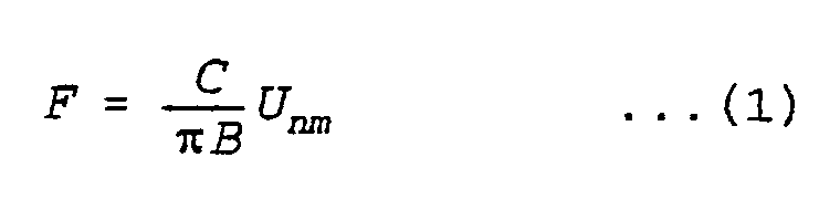
where, - B
- : cylinder bore diameter
- C
- : sonic velocity
- Unm
- : natural frequency of a vibrational mode
- From the equation (1), knocking is determined by a relationship between B and C. Thereby, the knocking frequency varies according to the diameter of the cylinder bore.
- Figure 3 shows the relationship between frequencies and outputs for a different type of
knock sensor 8. For a non-resonant type knock sensor, the output thereof is kept constant throughout the whole frequency range, though the magnitude of its output is very small. On the other hand, for a resonant type knock sensor, the output thereof becomes very large at a specific frequency. Further, for a wide-range resonant type knock sensor, though an amplitude of its output is smaller than that of the resonant type knock sensor, its resonance range extends to a wider range of the frequency. - Figure 4 shows ratios of cylinder pressures at knocking to those without knocking relative to the frequency. It is shown in Figure 4 that the pressure ratios become large at 7.9KHz, 13.8KHz, 18.5KHz, and 22KHz, thus exemplifying large pressure increases during knocking which is widely dispersed in frequency. Thus, a wide range resonant type knock sensor capable of detecting many knocking frequencies is preferred. However, the resonant type knock sensor may alternatively be used by setting its resonance point in accordance with the cylinder bore diamter.
- Figures 5(a) and (b) show the relationship between engine crank angle and knock sensor output. Figure 5(a) shows the case of a resonant type knock sensor. Knocking phenomena are caused by reciprocating pressure waves travelling inside the cylinder, which are genrated by self-detonation of mixtures due to an increase in cylinder pressure during combustion of mixtures in the cylinder. Therefore, knocking occurs delayed in time after the ignition. In the case of the resonant type sensor, its output is generated in the range of resonant frequencies. On the other hand, Figure 5(b) shows the case of a wide range resonance type knock sensor. As shown in the Figure 5(b), the sensor output is output as a synthesized wave of many frequencies. In both cases, knocking is initiated, with ignition as the starting point, but delayed in time from ignition. Thus, when controlling the sample and hold
circuit 11 with the signal online 15 from thecontrol circuit 2, a sampling start signal may be generated with the instant of ignition as its starting point. - The sampling period of the sample and hold
circuit 11 is advantageously set at about one tenth of the maximum measurement frequency for a wide range resonant type knock sensor. In other words, it is required to measure knock signals at predetermined intervals (preferably one tenth maximum measurement frequency) and again measure the knock signals at a next cylinder firing stroke of the cylinder of concern, the signals passing through the neural computer and then being compared to remove the effect of the noise component. The sampling period may be satisfactory if the minimum measurement frequency is less than the period of a minimum cycle, the sampling periods being less than the minimum measurement frequency. - For a resonant type knock sensor, sampling is preferably taken for more than one cycle at one tenth of the resonance frequency, as stated above.
- A
neural element 23, a constitutuent of aneural computer 13 is shown in Figure 6 having inputs Ok' Oj and Oℓ multiplied in the neural element with weighting factor, Wik, Wij, Wiℓ respectively, and the output Oi is expressed as follows.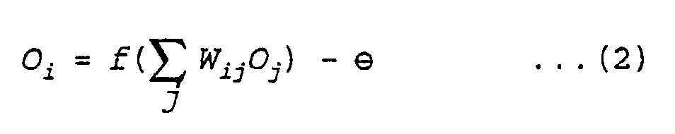
where, ⊖ is a threshold. - The output Oi is then inputted to the next neural element.
- However, there are two types of output Oi; one which changes stepwise as shown in Figure 7 becoming 1 when exceeding the threshold ⊖; the other, as shown in Figure 8, represented by a Sigmoid function as follows.

In the present invention, where the output is desired to become proportional to the knocking intensity, a Sigmoid function representation is advantageous. - In Figure 9, part of the configuration of the neural elements in a neural computer is shown. The neural computer has neural elements arranged in an input layer, an intermediate layer and an output layer. In the input layer, there are provided
neural elements lines sample hold circuit 11 in sequence. The output from theneural element 30a is inputted toneural elements neural elements neural elements neural elements neural elements neural element 32 in the output layer, output fromneural element 32 having a threshold value ⊖₂ which is subtracted from the output signal ofneural element 32. - A flow diagram explaining the learning process for respective weighting factors and thresholds in the
neural computer 13 is shown in Figure 10. InStep 33, actual knock signal data is inputted to the input layer. Then it is judged inStep 34, whether data outputted to the output layer is correct. If yes, advance is made to Step 35, wherein the weighting factor of a correct solution route is increased. Similarly, in such a situation the thresholds ⊖₁ and ⊖₂ may alternatively be decreased. A difference from the correct solution is judged inStep 37, and when the error is below a predetermined amount, the flow sequence is completed. If the error is above the predetermined level, the sequence returns to Step 34, where weighting factors and thresholds are repeatedly readjusted until the error determined inStep 37 is acceptable. Through learning as described above over a number of cycles, a high percentage of correct solutions can be attained. - An exemplary configuration of a neural computer using a wide range resonance
type knock sensor 8 is shown in Figure 11. If thesensor 8 output is supposed to resonate at knocking frequencies 7.9KHz, 13.8KHz and 18.5KHz, its sampling cycle which is a function of the highest knocking frequency is represented as follows,
where 10 is the number of required sampling points, and its sampling period is therefore
Therefore, the minimum number of input elements =
Thus:
The input layer : 30 elements
The intermediate layer : 3 elements
The output layer : 1 element
Total : 34 elements - From the above, in general the number of input elements is one cycle of sensor output waveform maximum frequency divided by the sampling period. Preferably, there are at least ten sampling points in each cycle. The configuration of these elements is shown in Figure 11. The input layer is composed of 30 neural elements, respective outputs thereof being inputted to the three neural elements in the intermediate layer. The outputs from the intermediate layer are inputted to one output layer neural element.
- The configuration in Figure 11 is one of the embodiments of the present invention, wherein detection precision may be further improved by increasing the number of neural elements in the input layer and the intermediate layer.
- Figures 12 to 14 show engineering arrangements of the
neural element 23 shown in Figure 6. Figure 12 shows an operational amplifier having amplification factor A, while Figures 13 and 14 show a transconductance amplifier having again 6, and an inverter, respectively. In each case, the following explanation applies. - vi⁺, vi⁻
- : input voltages
- vo⁺, vo⁻
- : output voltages
- Figures 15 and 16 show configurations of the coupling transistors in the input stages shown in Figures 12 and 13. Figure 15 is an example showing bipolar transistors, and Figure 16 is an example showing CMOS transistors. In the Figures 15, 16 KB, DB,KM and DM are respective constants, IEE and ISS are output values.
- In Figures 17 to 19, there are shown block diagrams for engineeringly obtaining weighting factors for the
neural element 23. In Figure 17, the triode region of an FET was used where K is a constant and R is input resistance. In Figure 18, a transconductance amplifier was used where R is input resistance and gm is gain, while in Figure 19 an array of 4 bit capacitors was used where c denotes capacitance and d denotes digital input. - Figure 20 shows in block schematic form an arrangement for storing weighting factors obtained by learning. The weighting factors which are stored in a
memory 40 of the computer in thecontrol circuit 2 are converted to analog signals in a D/A converter 41 for driving an FET. - Figure 21 shows another exemplary embodiment using a resonant
type knock sensor 8. Time series signals from theknock sensor 8 are transformed into spatial multi-variable signals in the sample and holdcircuit 11, the output signals from which are designated as being onlines 12a - 12f. Thesesignal lines 12a - 12f are inputted to a neural computer having an input layer and an output layer havingoutput lines 43a - 43f, wherein the numbers of neural elements in the input layer and the output layer are set to be equal. Further, a sampling cycle is set to be 1/4 of the resonant frequency, and the sampling time is the same as the resonant frequency. The signal atline 43a is thus minus the components of the resonant frequency, and therefore consists mostly of noise components. Therefore, by deducting the original signals inputted to the input layer from the signals onlines 43a - 43f respectively, in subtractors, there are obtained noise-free resonance frequency signals onlines 44a - 44f. In acircuit 42, the difference between the maximum value and the minimum value insignals 44a - 44f is calculated to be used as a knocking detection signal. - Figure 22 shows respective signals in each portion at the various lines of Figure 21. Figure 22(a) shows input signals 12a - 12f; Figure 22b shows the noise signals 43c - 43f; and Figure 22(c) shows the
resonant frequency signals 44a - 44f. In the embodiment of Figure 21, the sampling was taken at a 1/4 cycle of the resonant frequency. However, by sampling at a smaller cycle, measurement precision can be improved. - Figure 23 is a schematic diagram of an engine control device using a neural network. Various object values are inputted to a
neural controller 50, and the resultant output is applied to anengine 51, which is the object of control. The particular condition being controlled in the engine is then fed back to theneural controller 50. In addition, there are provided, routines by anerror feedback device 52. The error feedback routines are for correcting a weighting factor W in the neural network of theneural controller 50, or a transformation function for neural elements. The error feedback routines detect differences between the objective values and the actual values representing engine state, especially when the differences are great in the manner described above in relation to Figures 9 and 10. - The arrangement shown in Figure 23 is a system for controlling air-fuel ratio state (condition) in an engine. An objective value r for the air-fuel ratio of the engine is outputted by a
controller 53 to theneural controller 50 and theerror feedback device 52. In addition, various quantities of engine state such as cooling water temperature Tw, the number of engine revolutions N, engine input air flow (indicative of load) Qa and the like are also inputted to theneural controller 50. An open period of a fuel injection valve (time T) is outputted from theneural controller 50. Given the time T, theengine 51 outputs a resultant actual air-fuel ratio (A/F) λ. The A/F ratio λ is fed back to theneural controller 50 and to theerror feedback device 52. Theerror feedback device 52 then determines the error difference between the objective value r, and the actual value λ. If there is a large difference of error, the configuration of theneural controller 50 is estimated to be inadequate, thus, demanding action to be taken for its reconfiguration. This reconfiguration can be executed through rewriting weighting factors in the neural network, or by transformation functions (Sigmoid Functions or the like), in the manner described hereinabove. - In Figure 24 the configuration of such a neural network is shown, which consists of an input layer i, an intermediate layer j and an output layer k. The output Oj from the intermediate layer is expressed as follows.

where, f is a transformation function, for instance, such as a Sigmoid function given hereinbefore. An output T is expressed as follows.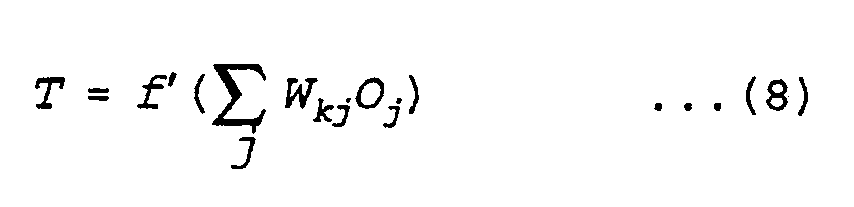
- Figure 25(a) shows the mode of function transformation in the intermediate layer j. Oj(1) shows the state at the first neural element in the intermediate layer, the sum of the inputs to which neural element is
The output of this function is transformed into a non-linear function to be Oj(1). The following outputs in the intermediate layer are determined likewise to be Oj(2), Oj(3), ... Then, the sum of the outputs from the intermediate layer
becomes an input to the neural element in the output layer as shown in Figure 25(b). Here, it is also transformed so as to yield an output T. The output T is then given to theengine 51. - In the present example, T is required to be determined as a time delay in transporting fuel during a transient state of the engine, and T may readily be given by choosing a desirable value in the functions in Figure 25(a). The
neural controller 50 may be considered to be a model simulating the internal state of theengine 51, wherein, very complicated phenomena such as the delay in transport of fuel and the like which are hard to describe mathematically can be corrected and compensated through repeated reconfiguration by a learning process, as will be described later herein. - The mode of reconfiguration in a neural network is shown in Figure 26(a), wherein an example is given which was obtained by rewriting a weighting factor for a neural element. The original state before learning is indicated by broken line (A) with its output being Oj(1). When its weighting factor is rewritten to W1i, through learning, it changes to a state as indicated by chain broken line (B) with its output being Oj(1)'. As explained above, an output different from the original can be obtained by rewriting the weighting factors.
- Figure 26(b) graphically shows another method for rewriting a transformation function so that a curve (A) shown in solid line in the Figure 26(b) obtained before learning can be changed to a curve (B) (shown in broken line) after learning by changing the threshold value. By this means, for the same input of
the output is changed from Oj(1) to Oj(1)'. That is, by changing the shape of the transformation (Sigmoid) function, learning can be performed. - A flowchart of learning in the
neural controller 50 for the arrangement of Figure 23 is shown in Figure 27. A learning operation is activated at every sampling of λ. InStep 54, an objective value is read. InStep 55, the actual A/C ratio value λ is read. In thenext Step 56, an error e is obtained. The error e, which is of course a variable, is expressed as follows.

- Based on the value of e, a correction quantity of T, i.e., ΔT, is calculated in
Step 57. Then, inStep 58, a modification program is started. - In Figure 28, a modification program is shown. When this program is started, ΔT(n) for the present sampling is read in
Step 591, and the ΔT(n-1) for the preceding sampling is read inStep 592, then the difference ΔE between both the present sample and preceding samples is obtained inStep 593. The magnitudes of ΔE are evaluated inStep 594 ~ 597 in comparison with reference values T₁ to T₄. In dependence upon their respective magnitudes, weighting factor W groups undergo fine adjustment inSteps 598 ~ 602. - Figure 29 shows an alternative modification program. Herein, Steps 591 ~ 597 are the same as in Figure 28, but in
Steps 603 ~ 607 the functions f₁ to f₅ are modified or corrected in dependence upon the magnitude of ΔE. - Selections in the weighting groups Wa to We in Figure 28, or the functions f₁ to f₅ in Figure 29, are made from preset programs, writing of which has been theoretically determined.
- In Figures 30(a), (b), a method for storing and reading modification or correction variable quantities is shown. As shown in Figure 30(a), after a modification program is completed, modified quantities (weighting factors or functions) are promptly stored in a battery backed up memory in order to retain learning effects. These modification quantities thus stored are fetched and read instantly after an ignition key switch is turned on (Figure 30(b)).
- Figure 31 shows an example of the effect of learning. Variations in λ, i.e., air-fuel ratio, are shown relative to the acceleration throttle opening angle ⊖ac. It is shown that the variation in λ becomes smaller through learning steps (shown in the lower figure) by lines from (A) to (C).
- As shown above, because the learning in a neural network can be accomplished by rewriting weighting factors, a great learning effect can be achieved even if the design engineer responsible for devising the engine control circuits does not know the exact model of the internal combustion engine.
- Figure 32 shows an example of a multi-variable control device using the present invention. In this embodiment, objective values of an air-fuel ratio A/F, a torque T and an acceleration g are given to a
neural controller 50 from acontroller 53. An injection valve opening time Tinj, an ignition timing Tig, a throttle valve opening angle ⊖th, a gear position in a transmission Ptr, and a line pressure OPℓ are output from theneural controller 50 to anautomobile 60. Actual values of air/fuel ratio (A/Fr), torque (Tr) and acceleration (gr) of the automobile are measured and are outputtted, to anerror feedback device 52, which also receives the objective values A/F, T and g, wherein, based on the errors and the correction quantities calculated as explained above with reference to Figures 27 to 30, theerror feedback device 52 provides reconstruction configuration data to the neural controller as required. The neural control can, thus, be applied to a multi-variable controller. - The construction of a
neural network 50 is shown in Figure 33. In addition to the objective values A/F, T, g, various quantities of engine state such as water temperature, intake air flow, engine revolutions, load and the like are inputted to the input layer for evaluation, transferred through intermediate layer j and output from layer k. - Figure 34 shows an arrangement of sensors on an automobile including a
controller 61 which includes theneural controller 50. - The
controller 61 receives inputs from a throttle opening angle (⊖ac)sensor 62, anair flow sensor 63, atorque sensor 64, anacceleration sensor 65, and provides outputs to anactuator 67 which electrically activates athrottle value 66, an ignition signal online 70 to anignition coil 69, an open value signal online 72 to an injection valve 71, a gear position signal online 74 to atransmission 73, and a hydraulic line pressure control signal OP₁ (not shown in the Figure) for controlling the transmission. As indicated, the foregoing multi-variables are controlled by theneural controller 50. - An example of a determining means for the objective values A/F, T, and g is given in Figure 35, wherein an acceleration throttle opening angle ⊖ac reflecting a driver's intention for action is used as an input so that the torque T and acceleration g may be accordingly determined. Representing the change in ⊖ac with time is ⊖̇ as is shown in Figure 35, from ⊖ac and ⊖̇ objective values may be retrieved from three different maps representative of A/F, T and g, respectively.
- Another example of determining objective values is shown in Figure 36, wherein a pair of neural controllers 50(A) and 50(B) are employed. In the neural controller 50(A), inputs are received from an acceleration throttle opening angle ⊖ac sensor, a braking angle ⊖br sensor, and a travelling speed V sensor, such that a driving environment for the automobile is evaluated. That is, it is evaluated whether the automobile is passing through an urban district, a highway, a traffic jam, a rough road (gravel, wet, or frozen), climbing a hill, or going down a slope, so as to determine optimum objective values to be given as torque and acceleration corresponding to such environments. These objective values thus determined are given to the neural controller 50(B) so as to control the various components in the car as described above.
- Thus, the example in Figure 32 explains a case where an automobile is controlled more in accordance with a driver's intended action, while the example in Figure 36 explains a case where the automobile is controlled to achieve an optimum driving performance matched to the environment.
- In the arrangement of Figure 37(a), there is an
automobile 115, avehicle control device 116, and an engine crankshaft oroutput torque sensor 117. The engine crankshaft or output torque is detected by the engine crankshaft oroutput torque sensor 117, and is evaluated in thevehicle control device 116 whether the torque is the same as the objective torque. If it is not the same as the objective torque, a parameter for varying the output torque of theengine 115 is changed and controlled so as to yield an output the same as the objective torque. - A control flow block diagram for the arrangement of Figure 37(a) is shown in Figure 37(b). An objective torque map is stored in a
memory 118. Thememory 118 is a RAM which is backed up, for example, by a ROM or a battery. The objective torque is, for example, a map of the engine revolutions and the load torque (shown in Figure 38). Instead of the load torque, a basic fuel injection pulse width, an intake pressure, a throttle valve opening angle or acceleration valve opening angle may alternatively be used. The objective torque is compared in a comparison means 119 with the actual engine crankshaft torque of the engine. When the actual torque does not agree with the objective torque, a parameter for varying the output torque is modified in a torque modification means 122 so as to change the output torque from theengine 115. As a means for modifying the torque, the throttle valve opening angle, amount of fuel, or ignition timing may be modified. The output torque of the engine is detected by a torque detection means 121. - Figure 39 shows an engine shaft torque detection means. An
engine crankshaft 103 interconnects, for example, fourpistons 100, the number of pistons not being limited thereto in this invention. On opposing ends of the crankshaft are installed asensor 101 and asensor 102 to detect rotation angles at the respective ends of the crankshaft. Signals from thesensors - In Figure 40, an example of the results of the measurements of the output torque for a single cylinder internal combustion engine are shown. The output torque is shown to undergo a complicated variation with change of the crank angle because of a synthesized effect of combustion pressure and cylinder inertial force. Further, in a multi-cylinder internal combustion engine, the detection of the engine output torque is more difficult because of the inclusion of synthesized output torque between each cylinder.
- Figure 41(a) to (c) shows examples of sensor outputs.
Sensor 101 andsensor 102 are, for example, a gear wheel and an electromagnetic pick-up. When the crankshaft is rotated, signals such as shown in Figure 41(a) and (b) are output from thesensors sensors

where Te is crankshaft torque and Δ⊖cr is the torsional angle of the crankshaft. - By means of the torsional angle Δ⊖cr in Equation (10), an output torque can be obtained. However, as described above, because the output torque tends to be influenced by combustion pressure and inertial forces, including the number of cylinders, the function f(Δ⊖cr) has previously been very difficult to obtain. It is especially difficult to obtain an output torque during high speed rotation of the engine because of the shorter time for processing and the increased value in torsional angles. Because of this, an approximated model for the function f(Δ⊖cr) has sometimes been used, but its precision has not been satisfactory. Further, when the precision of the model is desired to be improved, a lot of time is needed for computing, thereby restricting practical application of the computation.
- In Figures 42(a) and (b), a torque detection method by using a neural computer is described. Phase differences Δ⊖₁, Δ⊖₂, Δ⊖₃ ..., Δ⊖n between signals taken in time series are inputted to the input layer of the neural computer. In this case, an output torque is outputted from the output layer. In an initial stage as shown in Figure 42(a), because the linkage or coupling between each layer is fairly uniform, a precise output torque cannot be obtained. However, as shown in Figure 42(b), through a process of having the neural computer learn correct output torques, the linkage between each layer can be optimized so that a correct output torque can be obtained. In other words, by giving the neural computer reference output torques in advance for learning, a subsequent output torque can be obtained without obtaining a f(Δ⊖cr). In addition, because of parallel computation of each signal, computation of the output torque can be completed in a shorter period of time.
- Figure 43 shows an exemplary configuration of the present invention. The outputs ⊖a and ⊖ from two sensors are inputted to a
circuit 120, wherein their phase difference Δ⊖ is obtained. The phase difference Δ⊖ is then inputted to apeak hold circuit 106, peak-held signals thereof are then fed to aneural computer 107. Thepeak hold circuit 106 is provided one for each input layer of the neural computer. Signals to be inputted to each input layer of the neural computer are given in time series. A sampling period is set from one to thirty degrees in terms of a crank rotation angle. ACPU 108 is provided for performing various operations which is connected to aROM 109 for reading programs, a battery backed-upRAM 110 for storing learning parameters in the neural computer, aRAM 111 for executing programs and the like, and an A/D converter 121 to input analog data. - Another embodiment of the present invention is shown in Figure 44. A phase difference signal is converted to a digital signal in an A/
D converter 118. The converted digital signal is then stored in aRAM 112, wherein A/D converted values are stored in a time series order in the RAM memory cells. The data stored in theRAM 112 is inputted to theneural computer 107 and fetch commands to theRAM 112 to read data in time series order are controlled by theCPU 108. Such a configuration can be made compact in size because there is no need for a peak hold circuit to fetch data as required in the arrangement of Figure 43. In addition, because of digitalized signals, they can be readily processed. - Figure 45 shows still another embodiment of the present invention, wherein fetch and read command of data to a
RAM 112 is controlled, not by themain CPU 108, but by another CPU 113 (smaller in scale than the main CPU); for instance, 8 bits are sufficient inCPU 118 as against 83 bits of themain CPU 108. In such a configuration, because data can be fetched without the help of the main CPU, burdens such as interruption processing and the like can be reduced substantially in the main CPU. - Figure 46 shows the basic operation of a neural computer.
- When the number of x signals to be processed by the neural computer is n
X = (x₁, x₂, ..., xn)
- While receiving information on S, the neural computer changes its internal parameters to match with the configuration of S. This implies that the neural computer automatically generates a model of S internally, in which to process information S. A neural field F receiving external signals is supposed to be uniform in spatial configuration, and its relative coupling method to be of a mutually restraining type. In other words, when one neuron in the field generates a signal, the output from the neuron induces other neurons in its vicinity also to generate signals, but to restrain other neurons located a little remotely from generating signals. In more detail, and referring to Figure 47, each neuron, when it comes into contact with an input signal x, receives its signal through its coupling load vector S, consequently receiving an intensity of stimulation of a total inner product expressed as follows.

- For example, when an input signal is x, an intensity of the signal received at a first neuron is expressed as follows.

where, x=x(x₁, x₂, x₃, ............xn) - Similarly, an intensity of the signal received at a second neuron s expressed by

- Then, an intensity of the signal received at an ith neuron will be

- Further, when internal signals between neurons, and restraint signals are considered, the intensity of the signal received at the ith neuron can be rewritten as follows:

- When this value exceeds a given quantity the neuron outputs an output signal. Assuming the responsive time constant of a neural to be τ, the following equation will be derived.
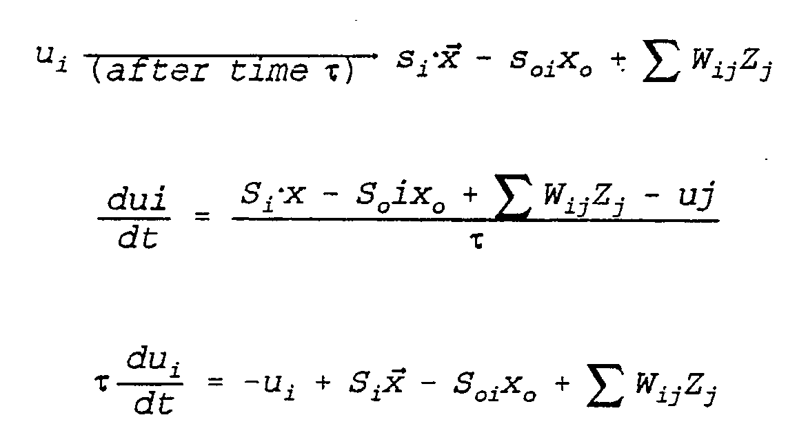
- From the above statements, it is understood that an output torque Te can also be obtained from a phase difference Δ⊖cr, if Wij in the neural computer is predetermined and optimized by obtaining the output torque during operation of an internal combustion engine such as by a torque sensor. The data of Wij obtained through learning is stored in a battery backup memory.
- A further use of the present invention on an automobile will now be described. On the front of an automobile, 146 shown in Figure 48, is a light emitting
device 141 forming a forward facing beam, and aphotoreceptor 142 for receiving light rays emitted bydevice 141 after the rays have been scattered by a road. The light emitting device may be, for example, a laser or an infra-red diode and the photoreceptor may be a phototransistor or a photodiode. - A plurality of
photoreceptors 144 may be arranged in a two-dimensional array as shown in Figure 49 and signals from thephotoreceptors 144 are applied to the input layer of theneural computer 107. - As shown in Figure 50, signal intensity varies according to the location of each photoreceptor. Further, signal intensity patterns vary, for instance, in dependence upon road conditions (dry, wet or frozen etc.), or the size or shape of an obstacle. In other words, through processing received data in the neural computer as above described, sizes of obstacles and various road conditions can be detected very quickly.
- With regard to various road conditions, these are predefined to the neural computer for processing and learning so as to optimize weighting factors and threshold values in the neural computer. By such means, the existence of an obstacle and road conditions can be comprehended so as to issue an early warning to a driver in good time or alternatively to optimize operational parameters.
- Figure 51 shows another apparatus for detecting the road conditions. A laser beam (not shown) emitted from the front of an automobile is reflected from the road and is received onto a
detector 143 throughlenses 147 andfilters 148 which extrapolates the required light wavelength from extraneous light so as to thereby examine the shape and intensity of a reflected light ray. Based on the data it is possible to find out road surface conditions and slant or curvature of the road in front of the automobile. - The above described methods referring to Figures 48 - 51 are based on a process in which a laser beam from a light emitting device is reflected on the road, scattered, and is detected by a photoreceptor. But if a high sensitivity CCD array is used as a photoreceptor, related information can be obtained using external light sources only. The use of this invention with a knocking sensor is shown in Figure 52 in which an
adder 200 receives a signal 198 (for instance, a knocking signal) and anothersignal 199, for instance, indicative of a relative torsional angle between the front (⊖₁) and rear (⊖₂) ends of a crankshaft, which are inputted atterminals differential amplifier 195. Thesignal 199 is obtained by subtracting a crankshaft frontalend angle signal 196 and a crankshaft rear end (ring gear end)angle signal 197 in asubtractor 195. Thereby, thesignal 199 is the torsional angle of the crankshaft, indicative of the engine output.Output 201 from theadder 200 is inputted to a sample and holdcircuit 210, wherein time series signals are transformed into spatial multi-variable series to be inputted to the input layer of aneural computer 220. Anoutput 221 from theneural computer 220 is a knocking signal and anoutput 222, is an engine output signal. - Although in this embodiment, two outputs are detected by using three input signals, it is also possible to obtain two outputs by using two input signals or more output signals if more than three input signals are applied.
- Figure 53 shows an embodiment of the present invention as applied to the measurement of deterioration of a
catalyst 230 in a catalytic converter. Outputs from anO₂ sensor 231 in the up-stream side of thecatalyst 230 and anotherO₂ sensor 232 in the down-stream side of the catalyst are inputted to asubtractor 233 and theoutput 237 thereof is then inputted to a sample and holdcircuit 234. Output fromcircuit 234 is inputted to aneural computer 235 for computation therein, so as to yield acatalyst deterioration output 236. - Figure 54 shows another embodiment of the present invention applied to the measurement of catalyst deterioration. A
neural computer 240 has an input signal online 246 from anO₂ sensor 231 positioned in the up-stream of the catalyst, a signal online 247 from anotherO₂ sensor 245 in the down-stream from the catalyst, anengine revolution signal 242, and a throttle opening signal online 244. The neural computer outputs a catalyst deterioration signal online 241. Instead of thethrottle opening signal 244 employed in this embodiment, an engine intake air flow signal or a suction pipe pressure may be used. - Figure 55 shows still another embodiment of the present invention. Into a
neural network 300 is inputted automotive information such as the number of engine revolutions, knock signals, water temperature, lubricant temperature, air flow, gear position, travelling speed, throttle valve opening, damping positions of suspensions, vibration of car body, etc. Also in theneural network 300, there is provided a final output mode. When there arises a difference between the final output and the comfort index set up at discretion by an operator, weighting factors W1, W2 and W3 are changed so as to match the final output with the comfort index.Intermediate outputs 301a - 305a are inputted to the final stage of the neural network, whileintermediate outputs 301b - 305b are inputted as objective values respectively to an air-fuel ratio control, an ignition timing control, a transmission control, a suspension control, and a throttle valve control. As described above, when an operator inputs a comfort index suited to his own preference, each object value of respective controls is changed so as to achieve a driving performance or mode coordinated to his preference. - Figure 56 shows a still further embodiment of the present invention, which can be used as a detector of the comfort index. Into a
neural network 300 are inputted the number of engine revolutions, knock signals, water temperature, lubricant temperature, air flow, gear position, travelling speed, throttle valve opening, damping positions of suspension, and vibration of car body. The output from theneural network 300 is compared with a comfort index as tutor data throughout a learning process by varying weighting factors. When the learning process is completed, theoutput 310 indicates the value of the comfort index. When another driver indicates his own preference of comfort index as tutor data, weighting factors are varied to yield different comfort index suited to his preference. - In the present invention, output signals from one or more sensors after being converted to a plurality of signals, are inputted into an input layer of hierarchical neural elements, which input signals therein are weighted to yield output signals reflecting weighting factors. Further, the yielded output signals are used as parameters to determine control parameters for one or more automobile control actuators, thereby significantly improving precision in extracting sensor information.
- Also, by use of the present invention, a driving performance or characteristic suited to a driver's preference or sensibilities can be attained because of an arrangement wherein output signals from a plurality of sensors are inputted to the input layer of hierarchical neural elements and based on the result of the final output from the neural elements, control actuators of an automobile are controlled.
Claims (16)
- A control device for an automobile having at least one sensor (8) adapted to detect an operational state of said automobile, and an actuator for controlling said operational state, said control device including a hierarchical group of neural elements adapted to receive an output signal from said at least one sensor, modifying means (Figures 17 - 19) for adaptively controlling the neural elements in accordance with a desired parameter and a control means (2) for receiving an output signal from said group of neural elements for controlling said actuator (5, 7).
- A control device as claimed in claim 1 wherein said modifying means includes means for varying weighting values of each neural element in the group of neural elements to provide said desired parameter.
- A control device as claimed in claim 1 wherein the modifying means includes a threshold modifying means for modifying a threshold value of said neural element in said hierarchical group of neural elements to provide said desired parameter.
- A control device as claimed in any preceding claim wherein a plurality of sensors (3, 4, 8) are provided for detecting an operational state of respective components in an automobile and at least one actuator (6, 7) is provided for controlling each said component of said automobile.
- A control device as claimed in claim 4 wherein a transformation means (11) is adapted to transform signals from said at least one sensor (8) into a plurality of signals time displaced from one another and to apply said time displaced signals to said hierarchical group of neural elements (13).
- A control device as claimed in claim 5 wherein there is provided a knock sensor (8) and signals therefrom are adapted to be applied to said transformation means (11), said time displaced signals being adapted to be supplied to said hierarchical group of neural elements (13), said group of neural elements comprising an input layer of neural elements, an intermediate layer of neural elements and an output layer of neural elements, difference means connected to each neural element of said output layer of neural elements, said difference means also being adapted to receive an input signal to an associated neural element of said input layer of neural elements whereby the output of said difference means provides substantially noise-free knocking signals which may be applied to said control means (Figure 21).
- A control device as claimed in claim 1 wherein a controller (53) is provided for providing predetermined, desired, sensor values to said hierarchical group of neural elements (50) and an error feedback means (52) is provided for receiving signals from said controller (53) and from said at least one sensor, said error feedback means (52) being adapted to modify the output of the neural elements in said hierarchical group of neural elements whereby the difference in signals applied to said error feedback means are brought to zero.
- A control device as claimed in claim 7 wherein the at least one sensor comprises a light emitter (141) and a light detector array (143) adapted to supply signals to said hierarchical group of neural elements (Figure 43).
- A control device as claimed in claim 1 wherein a plurality of sensors are provided and a plurality of control means are provided, and driver actuable means are provided adapted to control the output of the hierarchical group of neural elements whereby operational parameters of the automobile may be varied in dependence upon said drivers preference (Figures 55 and 56).
- A control device for an automobile including target value producing means (53) for producing a desired target value of a predetermined parameter, a hierarchical group of neural elements (50) for receiving said target value from said target value producing means whereby said neural elements are adapted to produce an output signal for a control variable based upon one of weighting and threshold values of said neural elements, actuator means (6) operable in accordance with said control variable, sensor means (8) for measuring an actual value of said predetermined parameter, comparator means (52) for comparing said actual value with said target value and for applying a difference signal indicative of said comparison means to control one of said weighting and threshold values of said neural elements.
- A control device as claimed in claim 10 wherein said target value producing means (53) is adapted to produce a plurality of target values each of which is adapted to be supplied to a neural element in said hierarchical group of neural elements.
- A control device for an automobile comprising:(a) a plurality of sensors (3, 4, 8) for detecting an operational state of at least one component in said automobile,(b) a hierarchical group of neural elements (13) adapted to receive output signals from said sensors,(c) a control variable decision means (2) for determining a control variable based on the output from said group of neural elements,(d) an actuator (6, 7) for controlling said at least one component in dependence upon the control variable determined by said control variable decision means.
- A control device as claimed in claim 12 wherein a weighting means is provided for weighting said sensor signals to be inputted to said neural elements.
- A control device as claimed in claim 13 wherein weighting modification means are provided for modifying a weighting ratio of said weighting means.
- A control device as claimed in claim 14 wherein a transformation means (11) is provided to receive input signals from said sensors and to apply a time displaced signal representative thereof to said hierarchical group of neural elements.
- An automobile including a control device as claimed in any preceding claim.
Applications Claiming Priority (2)
| Application Number | Priority Date | Filing Date | Title |
|---|---|---|---|
| JP2028291A JP2792633B2 (en) | 1990-02-09 | 1990-02-09 | Control device |
| JP28291/90 | 1990-02-09 |
Publications (3)
| Publication Number | Publication Date |
|---|---|
| EP0441522A2 true EP0441522A2 (en) | 1991-08-14 |
| EP0441522A3 EP0441522A3 (en) | 1991-10-02 |
| EP0441522B1 EP0441522B1 (en) | 1994-03-30 |
Family
ID=12244512
Family Applications (1)
| Application Number | Title | Priority Date | Filing Date |
|---|---|---|---|
| EP91300704A Expired - Lifetime EP0441522B1 (en) | 1990-02-09 | 1991-01-30 | Control device for an automobile |
Country Status (5)
| Country | Link |
|---|---|
| US (1) | US5361213A (en) |
| EP (1) | EP0441522B1 (en) |
| JP (1) | JP2792633B2 (en) |
| KR (1) | KR100196443B1 (en) |
| DE (1) | DE69101501T2 (en) |
Cited By (14)
| Publication number | Priority date | Publication date | Assignee | Title |
|---|---|---|---|---|
| EP0615892A1 (en) * | 1993-03-17 | 1994-09-21 | Mitsubishi Jidosha Kogyo Kabushiki Kaisha | Vehicle slip angle measuring method and a device therefor |
| WO1995004878A1 (en) * | 1993-08-05 | 1995-02-16 | Pavilion Technologies, Inc. | Virtual emissions monitor for automobile |
| EP0659996A3 (en) * | 1993-12-09 | 1995-09-13 | Daimler Benz Aerospace Ag | Apparatus to diagnose and control an internal combustion engine or electric motor. |
| WO1996005421A1 (en) * | 1994-08-11 | 1996-02-22 | Mecel Ab | Method and system for controlling combustion engines |
| FR2747429A1 (en) * | 1996-04-16 | 1997-10-17 | Renault | NEURON NETWORK ENGINE CONTROL SYSTEM FOR A MOTOR VEHICLE |
| EP0724073A3 (en) * | 1995-01-27 | 1998-09-30 | Matsushita Electric Industrial Co., Ltd. | Air-fuel ratio control system |
| WO1999025580A1 (en) * | 1997-11-13 | 1999-05-27 | Siemens Aktiengesellschaft | Drive regulating system for vehicles especially for motor vehicles |
| FR2772427A1 (en) * | 1997-12-12 | 1999-06-18 | Renault | NEURON NETWORK ENGINE CONTROL SYSTEM |
| WO2000009357A1 (en) * | 1998-08-12 | 2000-02-24 | Lucas Industries Plc | Method of and apparatus for controlling headway |
| EP0810363A3 (en) * | 1996-05-28 | 2000-05-31 | Matsushita Electric Industrial Co., Ltd. | Air/fuel ratio control apparatus that uses a neural network |
| US7177743B2 (en) | 2003-06-02 | 2007-02-13 | Toyota Engineering & Manufacturing North America, Inc. | Vehicle control system having an adaptive controller |
| WO2007020456A3 (en) * | 2005-08-19 | 2007-08-16 | Axeon Ltd | Neural network method and apparatus |
| CN107856670A (en) * | 2017-11-06 | 2018-03-30 | 吉林大学 | A kind of optimal control Rules extraction method of planetary hybrid power system |
| CN109130759A (en) * | 2018-10-10 | 2019-01-04 | 鸿科(南京)汽车零部件有限公司 | A kind of airsuspension system having a display function |
Families Citing this family (88)
| Publication number | Priority date | Publication date | Assignee | Title |
|---|---|---|---|---|
| US5608633A (en) * | 1991-07-29 | 1997-03-04 | Nissan Motor Co., Ltd. | System and method for detecting knocking for internal combustion engine |
| US5532929A (en) * | 1992-12-16 | 1996-07-02 | Toyota Jidosha Kabushiki Kaisha | Apparatus for controlling vehicle driving power |
| US5454358A (en) * | 1993-02-26 | 1995-10-03 | Toyota Jidosha Kabushiki Kaisha | Driving power control apparatus for internal combustion engine |
| US5477825A (en) * | 1993-02-26 | 1995-12-26 | Toyota Jidosha Kabushiki Kaisha | Driving power control apparatus for vehicle |
| JP3357159B2 (en) * | 1993-08-10 | 2002-12-16 | 三菱自動車工業株式会社 | Vehicle driving operation state estimating method and vehicle driving characteristic control method |
| US5517970A (en) * | 1994-06-23 | 1996-05-21 | Mitsubishi Jidosha Kogyo Kabushiki Kaisha | Fuel feeding system and method for internal combustion engine |
| JP3508328B2 (en) * | 1995-10-03 | 2004-03-22 | 松下電器産業株式会社 | Air-fuel ratio control device |
| US5699253A (en) * | 1995-04-05 | 1997-12-16 | Ford Global Technologies, Inc. | Nonlinear dynamic transform for correction of crankshaft acceleration having torsional oscillations |
| US5587524A (en) * | 1995-05-03 | 1996-12-24 | Ford Motor Company | Misfire detection assembly |
| US5675505A (en) * | 1995-07-10 | 1997-10-07 | Chrysler Corporation | Sine on random data analysis method for simulating engine vibration |
| US5781700A (en) * | 1996-02-05 | 1998-07-14 | Ford Global Technologies, Inc. | Trained Neural network air/fuel control system |
| US5745653A (en) * | 1996-02-05 | 1998-04-28 | Ford Global Technologies, Inc. | Generic neural network training and processing system |
| US6092018A (en) * | 1996-02-05 | 2000-07-18 | Ford Global Technologies, Inc. | Trained neural network engine idle speed control system |
| JPH09257553A (en) * | 1996-03-22 | 1997-10-03 | Yazaki Corp | Self-weight measuring device |
| US5835868A (en) * | 1996-08-30 | 1998-11-10 | Mcelroy; Alejandro S. | Automated system for immobilizing a vehicle and method |
| US6032139A (en) * | 1996-09-27 | 2000-02-29 | Yamaha Hatsudoki Kabushiki Kaisha | Electronic controller using genetic evolution techniques suitable for controlling a motor |
| JP3825845B2 (en) * | 1996-09-27 | 2006-09-27 | ヤマハ発動機株式会社 | Evolutionary control method |
| JP3785703B2 (en) * | 1996-10-31 | 2006-06-14 | 株式会社明電舎 | Time series data identification method and identification apparatus |
| US5732382A (en) * | 1996-11-06 | 1998-03-24 | Ford Global Technologies, Inc. | Method for identifying misfire events of an internal combustion engine |
| US6236908B1 (en) * | 1997-05-07 | 2001-05-22 | Ford Global Technologies, Inc. | Virtual vehicle sensors based on neural networks trained using data generated by simulation models |
| US5774823A (en) * | 1997-09-04 | 1998-06-30 | Ford Global Technologies, Inc. | Method of generation correction tables for misfire detection using neural networks |
| US6018729A (en) * | 1997-09-17 | 2000-01-25 | Lockheed Martin Energy Research Corporation | Neural network control of spot welding |
| US6223121B1 (en) | 1998-02-06 | 2001-04-24 | Matsushita Electric Industrial Co. | Air-to-fuel ratio control device |
| US6678640B2 (en) | 1998-06-10 | 2004-01-13 | Matsushita Electric Industrial Co., Ltd. | Method and apparatus for parameter estimation, parameter estimation control and learning control |
| US6397112B1 (en) | 1998-12-18 | 2002-05-28 | Chrysler Corporation | Zone adaptive cell breakdown |
| US6240343B1 (en) * | 1998-12-28 | 2001-05-29 | Caterpillar Inc. | Apparatus and method for diagnosing an engine using computer based models in combination with a neural network |
| DE19961943A1 (en) * | 1999-12-22 | 2001-07-12 | Bosch Gmbh Robert | Control method of an internal combustion engine when a backwards movement of the wheel is detected, involves modification of the ignition angle and the air intake ratio |
| CN1253830C (en) * | 2001-02-21 | 2006-04-26 | 索尼公司 | Signal processing device |
| DE102004031006A1 (en) * | 2003-07-23 | 2005-04-28 | Daimler Chrysler Ag | Combustion monitoring system for common rail direct injection diesel engine has pressure readings from sensor in common rail filtered through neural net |
| JP4734292B2 (en) * | 2007-05-31 | 2011-07-27 | 本田技研工業株式会社 | Knock sensor placement |
| WO2011039807A1 (en) * | 2009-09-30 | 2011-04-07 | トヨタ自動車株式会社 | Damping control device |
| US20110297462A1 (en) | 2010-06-03 | 2011-12-08 | Polaris Industries Inc. | Electronic throttle control |
| US8636620B2 (en) | 2010-10-28 | 2014-01-28 | Jatco Ltd | Automatic transmission |
| JP5496854B2 (en) | 2010-11-01 | 2014-05-21 | ジヤトコ株式会社 | Vehicle control device |
| JP5496855B2 (en) | 2010-11-01 | 2014-05-21 | ジヤトコ株式会社 | Vehicle control device |
| JP5693151B2 (en) | 2010-11-01 | 2015-04-01 | ジヤトコ株式会社 | Vehicle control device |
| JP5693152B2 (en) | 2010-11-01 | 2015-04-01 | ジヤトコ株式会社 | Vehicle hydraulic control device |
| JP5383626B2 (en) | 2010-11-01 | 2014-01-08 | ジヤトコ株式会社 | Vehicle control device |
| JP5501937B2 (en) * | 2010-11-02 | 2014-05-28 | ジヤトコ株式会社 | Control device for hybrid vehicle |
| JP5501260B2 (en) | 2011-02-03 | 2014-05-21 | ジヤトコ株式会社 | Vehicle control device |
| JP5561283B2 (en) * | 2012-01-11 | 2014-07-30 | 株式会社デンソー | Sensor signal processing device |
| US9205717B2 (en) | 2012-11-07 | 2015-12-08 | Polaris Industries Inc. | Vehicle having suspension with continuous damping control |
| ES2699245T3 (en) * | 2012-11-07 | 2019-02-08 | Polaris Inc | Vehicle with suspension with continuous damping control |
| US9446768B2 (en) * | 2014-03-26 | 2016-09-20 | Ford Global Technologies, Llc | System and method for energy optimization in autonomous vehicle operation |
| CA2965309C (en) | 2014-10-31 | 2024-01-23 | Polaris Industries Inc. | System and method for controlling a vehicle |
| DE102014222779A1 (en) * | 2014-11-07 | 2016-05-12 | Schaeffler Technologies AG & Co. KG | Method for vibration damping of a drive train by means of an electric machine |
| US9556810B2 (en) | 2014-12-31 | 2017-01-31 | General Electric Company | System and method for regulating exhaust gas recirculation in an engine |
| US9752949B2 (en) | 2014-12-31 | 2017-09-05 | General Electric Company | System and method for locating engine noise |
| US9803567B2 (en) | 2015-01-07 | 2017-10-31 | General Electric Company | System and method for detecting reciprocating device abnormalities utilizing standard quality control techniques |
| US9874488B2 (en) | 2015-01-29 | 2018-01-23 | General Electric Company | System and method for detecting operating events of an engine |
| US9528445B2 (en) | 2015-02-04 | 2016-12-27 | General Electric Company | System and method for model based and map based throttle position derivation and monitoring |
| US9903778B2 (en) | 2015-02-09 | 2018-02-27 | General Electric Company | Methods and systems to derive knock sensor conditions |
| US9791343B2 (en) | 2015-02-12 | 2017-10-17 | General Electric Company | Methods and systems to derive engine component health using total harmonic distortion in a knock sensor signal |
| US10001077B2 (en) | 2015-02-19 | 2018-06-19 | General Electric Company | Method and system to determine location of peak firing pressure |
| US9915217B2 (en) | 2015-03-05 | 2018-03-13 | General Electric Company | Methods and systems to derive health of mating cylinder using knock sensors |
| US9695761B2 (en) | 2015-03-11 | 2017-07-04 | General Electric Company | Systems and methods to distinguish engine knock from piston slap |
| US9435244B1 (en) | 2015-04-14 | 2016-09-06 | General Electric Company | System and method for injection control of urea in selective catalyst reduction |
| US9784231B2 (en) | 2015-05-06 | 2017-10-10 | General Electric Company | System and method for determining knock margin for multi-cylinder engines |
| US9933334B2 (en) | 2015-06-22 | 2018-04-03 | General Electric Company | Cylinder head acceleration measurement for valve train diagnostics system and method |
| US9784635B2 (en) | 2015-06-29 | 2017-10-10 | General Electric Company | Systems and methods for detection of engine component conditions via external sensors |
| US10393609B2 (en) | 2015-07-02 | 2019-08-27 | Ai Alpine Us Bidco Inc. | System and method for detection of changes to compression ratio and peak firing pressure of an engine |
| CN106401757B (en) * | 2015-07-28 | 2019-07-05 | 长城汽车股份有限公司 | Disconnected cylinder mode implementation method, system and the vehicle of engine |
| US9897021B2 (en) | 2015-08-06 | 2018-02-20 | General Electric Company | System and method for determining location and value of peak firing pressure |
| JP6288066B2 (en) * | 2015-12-24 | 2018-03-07 | マツダ株式会社 | Fuel injection control method and fuel injection control device for compression self-ignition engine |
| JP6341235B2 (en) * | 2016-07-20 | 2018-06-13 | トヨタ自動車株式会社 | Engine air-fuel ratio control device |
| DE102016216950A1 (en) * | 2016-09-07 | 2018-03-08 | Robert Bosch Gmbh | Model calculation unit and control unit for calculating a multilayer perceptron model with feedforward and feedback |
| DE102016216944A1 (en) * | 2016-09-07 | 2018-03-08 | Robert Bosch Gmbh | Method for calculating a neuron layer of a multilayer perceptron model with a simplified activation function |
| DE102016216947A1 (en) | 2016-09-07 | 2018-03-08 | Robert Bosch Gmbh | Model calculation unit and control unit for calculating a multi-layer perceptron model |
| CN110121438B (en) | 2016-11-18 | 2023-01-31 | 北极星工业有限公司 | vehicles with adjustable suspension |
| US10196997B2 (en) * | 2016-12-22 | 2019-02-05 | GM Global Technology Operations LLC | Engine control system including feed-forward neural network controller |
| JP6914084B2 (en) * | 2017-04-10 | 2021-08-04 | 株式会社デンソーテン | Knock control device, knock matching method and knock matching program |
| US10406884B2 (en) | 2017-06-09 | 2019-09-10 | Polaris Industries Inc. | Adjustable vehicle suspension system |
| US10760543B2 (en) | 2017-07-12 | 2020-09-01 | Innio Jenbacher Gmbh & Co Og | System and method for valve event detection and control |
| JP6501018B1 (en) * | 2018-04-20 | 2019-04-17 | トヨタ自動車株式会社 | Machine learning device for unburned fuel |
| US10987987B2 (en) | 2018-11-21 | 2021-04-27 | Polaris Industries Inc. | Vehicle having adjustable compression and rebound damping |
| JP7231144B2 (en) * | 2019-07-17 | 2023-03-01 | 株式会社トランストロン | Engine control device and neural network program it has |
| WO2021059791A1 (en) * | 2019-09-26 | 2021-04-01 | 日立Astemo株式会社 | Internal combustion engine control device |
| KR102791613B1 (en) * | 2019-12-31 | 2025-04-08 | 현대자동차주식회사 | Method for sensing closing time of injector using artificial neural network and feature amount of non-linear regression in exponential function and control method of fuel injector using it |
| KR102791615B1 (en) * | 2019-12-31 | 2025-04-08 | 현대자동차주식회사 | Method for sensing opening time of injector using artificial neural network and feature vector of current and voltage and control method of fuel injector using it |
| KR102791614B1 (en) * | 2019-12-31 | 2025-04-08 | 현대자동차주식회사 | Method for sensing closing time of injector using artificial neural network and control method of fuel injector using it |
| US11459962B2 (en) * | 2020-03-02 | 2022-10-04 | Sparkcognitton, Inc. | Electronic valve control |
| DE112021001704T5 (en) * | 2020-03-18 | 2023-02-02 | Hitachi Astemo, Ltd. | Vehicle control device, vehicle control method and vehicle control system |
| MX2022013889A (en) | 2020-05-20 | 2022-11-30 | Polaris Inc | Systems and methods of adjustable suspensions for off-road recreational vehicles. |
| CA3182725A1 (en) | 2020-07-17 | 2022-01-20 | Polaris Industries Inc. | Adjustable suspensions and vehicle operation for off-road recreational vehicles |
| US11434839B2 (en) * | 2020-12-30 | 2022-09-06 | Tula Technology, Inc. | Use of machine learning for detecting cylinder intake and/or exhaust valve faults during operation of an internal combustion engine |
| JP7487709B2 (en) * | 2021-06-02 | 2024-05-21 | トヨタ自動車株式会社 | Vehicle drive unit control device and control method |
| CN114537400B (en) * | 2022-01-13 | 2025-06-17 | 南京航空航天大学 | Intelligent driver model construction method based on CMAC |
| CN117841591B (en) * | 2024-03-06 | 2024-05-07 | 江苏智能无人装备产业创新中心有限公司 | ISD suspension control method based on improved fuzzy neural network PID |
Family Cites Families (18)
| Publication number | Priority date | Publication date | Assignee | Title |
|---|---|---|---|---|
| DE3111135A1 (en) * | 1980-06-20 | 1982-03-11 | Robert Bosch Gmbh, 7000 Stuttgart | METHOD FOR CONTROLLING THE COMBUSTION IN THE COMBUSTION ROOMS OF AN INTERNAL COMBUSTION ENGINE |
| JPH0650103B2 (en) * | 1982-01-18 | 1994-06-29 | 株式会社日立製作所 | Knock control device |
| JPS60163731A (en) * | 1984-02-07 | 1985-08-26 | Nissan Motor Co Ltd | Car speed controlling device |
| US4617895A (en) * | 1984-05-17 | 1986-10-21 | Nippondenso Co., Ltd. | Anti-knocking control in internal combustion engine |
| JPH0672563B2 (en) * | 1986-04-28 | 1994-09-14 | マツダ株式会社 | Engine throttle control device |
| GB8629346D0 (en) * | 1986-12-09 | 1987-01-21 | Lucas Ind Plc | Engine control |
| JPS63250216A (en) * | 1987-04-06 | 1988-10-18 | Nec Ic Microcomput Syst Ltd | Erroneous action preventing circuit |
| US4868755A (en) * | 1987-05-18 | 1989-09-19 | Texas Instruments Incorporated | Expert vehicle control system |
| JP2717665B2 (en) * | 1988-05-31 | 1998-02-18 | 株式会社豊田中央研究所 | Combustion prediction determination device for internal combustion engine |
| JPH07107421B2 (en) * | 1988-07-06 | 1995-11-15 | 日産自動車株式会社 | Vehicle shift control device |
| JP2770332B2 (en) * | 1988-07-27 | 1998-07-02 | 日産自動車株式会社 | Vehicle suspension control device |
| JP2762504B2 (en) * | 1989-01-09 | 1998-06-04 | 日産自動車株式会社 | Vehicle speed change control device |
| JPH02287860A (en) * | 1989-04-28 | 1990-11-27 | Omron Corp | Information processor |
| US5041976A (en) * | 1989-05-18 | 1991-08-20 | Ford Motor Company | Diagnostic system using pattern recognition for electronic automotive control systems |
| US4971007A (en) * | 1989-09-25 | 1990-11-20 | Ford Motor Company | System and method for combined knock and torque timing control |
| JPH03132415A (en) * | 1989-10-17 | 1991-06-05 | Mitsubishi Electric Corp | automobile control device |
| JP2764832B2 (en) * | 1989-11-15 | 1998-06-11 | 本田技研工業株式会社 | Vehicle control method |
| US5044195A (en) * | 1990-08-24 | 1991-09-03 | Ford Motor Company | Misfire detection in an internal combustion engine |
-
1990
- 1990-02-09 JP JP2028291A patent/JP2792633B2/en not_active Expired - Fee Related
-
1991
- 1991-01-30 EP EP91300704A patent/EP0441522B1/en not_active Expired - Lifetime
- 1991-01-30 DE DE69101501T patent/DE69101501T2/en not_active Expired - Fee Related
- 1991-02-07 KR KR1019910002063A patent/KR100196443B1/en not_active Expired - Fee Related
-
1993
- 1993-03-24 US US08/037,732 patent/US5361213A/en not_active Expired - Fee Related
Cited By (17)
| Publication number | Priority date | Publication date | Assignee | Title |
|---|---|---|---|---|
| US5579245A (en) * | 1993-03-17 | 1996-11-26 | Mitsubishi Jidosha Kogyo Kabushiki Kaisha | Vehicle slip angle measuring method and a device therefor |
| EP0615892A1 (en) * | 1993-03-17 | 1994-09-21 | Mitsubishi Jidosha Kogyo Kabushiki Kaisha | Vehicle slip angle measuring method and a device therefor |
| WO1995004878A1 (en) * | 1993-08-05 | 1995-02-16 | Pavilion Technologies, Inc. | Virtual emissions monitor for automobile |
| EP0659996A3 (en) * | 1993-12-09 | 1995-09-13 | Daimler Benz Aerospace Ag | Apparatus to diagnose and control an internal combustion engine or electric motor. |
| WO1996005421A1 (en) * | 1994-08-11 | 1996-02-22 | Mecel Ab | Method and system for controlling combustion engines |
| EP0724073A3 (en) * | 1995-01-27 | 1998-09-30 | Matsushita Electric Industrial Co., Ltd. | Air-fuel ratio control system |
| FR2747429A1 (en) * | 1996-04-16 | 1997-10-17 | Renault | NEURON NETWORK ENGINE CONTROL SYSTEM FOR A MOTOR VEHICLE |
| EP0810363A3 (en) * | 1996-05-28 | 2000-05-31 | Matsushita Electric Industrial Co., Ltd. | Air/fuel ratio control apparatus that uses a neural network |
| WO1999025580A1 (en) * | 1997-11-13 | 1999-05-27 | Siemens Aktiengesellschaft | Drive regulating system for vehicles especially for motor vehicles |
| US6301542B1 (en) | 1997-11-13 | 2001-10-09 | Siemens Aktiengesellschaft | Cruise control system for vehicles, in particular for motor vehicles |
| FR2772427A1 (en) * | 1997-12-12 | 1999-06-18 | Renault | NEURON NETWORK ENGINE CONTROL SYSTEM |
| WO2000009357A1 (en) * | 1998-08-12 | 2000-02-24 | Lucas Industries Plc | Method of and apparatus for controlling headway |
| US7177743B2 (en) | 2003-06-02 | 2007-02-13 | Toyota Engineering & Manufacturing North America, Inc. | Vehicle control system having an adaptive controller |
| WO2007020456A3 (en) * | 2005-08-19 | 2007-08-16 | Axeon Ltd | Neural network method and apparatus |
| CN107856670A (en) * | 2017-11-06 | 2018-03-30 | 吉林大学 | A kind of optimal control Rules extraction method of planetary hybrid power system |
| CN107856670B (en) * | 2017-11-06 | 2019-03-08 | 吉林大学 | A kind of optimal control Rules extraction method of planetary hybrid power system |
| CN109130759A (en) * | 2018-10-10 | 2019-01-04 | 鸿科(南京)汽车零部件有限公司 | A kind of airsuspension system having a display function |
Also Published As
| Publication number | Publication date |
|---|---|
| EP0441522A3 (en) | 1991-10-02 |
| EP0441522B1 (en) | 1994-03-30 |
| DE69101501D1 (en) | 1994-05-05 |
| JPH03235723A (en) | 1991-10-21 |
| US5361213A (en) | 1994-11-01 |
| KR910015446A (en) | 1991-09-30 |
| JP2792633B2 (en) | 1998-09-03 |
| KR100196443B1 (en) | 1999-06-15 |
| DE69101501T2 (en) | 1994-10-20 |
Similar Documents
| Publication | Publication Date | Title |
|---|---|---|
| US5361213A (en) | Control device for an automobile | |
| KR940005030B1 (en) | Analogical control system and method | |
| US5410477A (en) | Control system for an automotive vehicle having apparatus for predicting the driving environment of the vehicle | |
| US5076098A (en) | System for detecting combustion state in internal combustion engine | |
| US6816799B2 (en) | Vehicle operating parameter determination system and method | |
| JP4583028B2 (en) | Method for estimating the mass of a vehicle driven on a road with varying slope and method for estimating the slope of a road | |
| US6688286B2 (en) | Knock control apparatus for engine | |
| EP1918688B1 (en) | Misfire detecting apparatus for internal combustion engine | |
| US11092130B2 (en) | Ignition timing control device for internal combustion engine | |
| US11307111B2 (en) | Knocking detection system and knocking detection method of internal combustion engine | |
| US6840218B2 (en) | Method for detecting and regulating the start of combustion in an internal combustion engine | |
| US5875411A (en) | Method of detecting combustion misfires by evaluating RPM fluctuations | |
| US8326518B2 (en) | Knocking detecting apparatus for internal combustion engine | |
| US5774823A (en) | Method of generation correction tables for misfire detection using neural networks | |
| JP7322826B2 (en) | Vehicle traveling direction estimation device | |
| JP3827727B2 (en) | Method for suppressing instability of automatic transmission for vehicle that always shifts from one gear ratio to upper and lower gear ratio | |
| JP3387004B2 (en) | Control device | |
| CN113844454B (en) | Road surface inclination angle calculation device | |
| JP2959310B2 (en) | Nutrunner control device | |
| EP0855588B1 (en) | Normalized misfire detection method | |
| JPH08277742A (en) | Car control equipment | |
| JPH10306744A (en) | Control device | |
| CN116679762A (en) | Optimized control method for flow guiding piece | |
| Zhou et al. | An automatic control method for semi-active suspension of driverless vehicle based on multi-sensor information fusion in complex environment | |
| Leonhardt et al. | Real time supervision of diesel engine injection with RBF-based neural networks |
Legal Events
| Date | Code | Title | Description |
|---|---|---|---|
| PUAI | Public reference made under article 153(3) epc to a published international application that has entered the european phase |
Free format text: ORIGINAL CODE: 0009012 |
|
| PUAL | Search report despatched |
Free format text: ORIGINAL CODE: 0009013 |
|
| 17P | Request for examination filed |
Effective date: 19910218 |
|
| AK | Designated contracting states |
Kind code of ref document: A2 Designated state(s): DE GB |
|
| AK | Designated contracting states |
Kind code of ref document: A3 Designated state(s): DE GB |
|
| 17Q | First examination report despatched |
Effective date: 19920214 |
|
| GRAA | (expected) grant |
Free format text: ORIGINAL CODE: 0009210 |
|
| AK | Designated contracting states |
Kind code of ref document: B1 Designated state(s): DE GB |
|
| REF | Corresponds to: |
Ref document number: 69101501 Country of ref document: DE Date of ref document: 19940505 |
|
| PLBE | No opposition filed within time limit |
Free format text: ORIGINAL CODE: 0009261 |
|
| STAA | Information on the status of an ep patent application or granted ep patent |
Free format text: STATUS: NO OPPOSITION FILED WITHIN TIME LIMIT |
|
| 26N | No opposition filed | ||
| K1C1 | Correction of patent application (title page) published |
Effective date: 19910814 |
|
| REG | Reference to a national code |
Ref country code: GB Ref legal event code: IF02 |
|
| PGFP | Annual fee paid to national office [announced via postgrant information from national office to epo] |
Ref country code: GB Payment date: 20021223 Year of fee payment: 13 |
|
| PGFP | Annual fee paid to national office [announced via postgrant information from national office to epo] |
Ref country code: DE Payment date: 20030310 Year of fee payment: 13 |
|
| PG25 | Lapsed in a contracting state [announced via postgrant information from national office to epo] |
Ref country code: GB Free format text: LAPSE BECAUSE OF NON-PAYMENT OF DUE FEES Effective date: 20040130 |
|
| PG25 | Lapsed in a contracting state [announced via postgrant information from national office to epo] |
Ref country code: DE Free format text: LAPSE BECAUSE OF NON-PAYMENT OF DUE FEES Effective date: 20040803 |
|
| GBPC | Gb: european patent ceased through non-payment of renewal fee |
Effective date: 20040130 |