EP0411428B1 - Windscreen washer pump for vehicle - Google Patents
Windscreen washer pump for vehicle Download PDFInfo
- Publication number
- EP0411428B1 EP0411428B1 EP90114107A EP90114107A EP0411428B1 EP 0411428 B1 EP0411428 B1 EP 0411428B1 EP 90114107 A EP90114107 A EP 90114107A EP 90114107 A EP90114107 A EP 90114107A EP 0411428 B1 EP0411428 B1 EP 0411428B1
- Authority
- EP
- European Patent Office
- Prior art keywords
- impeller
- supplemental
- pump chamber
- washer
- inlet
- Prior art date
- Legal status (The legal status is an assumption and is not a legal conclusion. Google has not performed a legal analysis and makes no representation as to the accuracy of the status listed.)
- Expired - Lifetime
Links
- 239000012530 fluid Substances 0.000 claims description 61
- 230000000153 supplemental effect Effects 0.000 claims description 44
- 238000005192 partition Methods 0.000 claims description 6
- 230000002093 peripheral effect Effects 0.000 claims description 4
- 239000000446 fuel Substances 0.000 description 2
- 239000011521 glass Substances 0.000 description 2
- 239000007921 spray Substances 0.000 description 2
- 238000005507 spraying Methods 0.000 description 2
- 238000011144 upstream manufacturing Methods 0.000 description 2
- 238000002485 combustion reaction Methods 0.000 description 1
- 230000003247 decreasing effect Effects 0.000 description 1
- 230000005484 gravity Effects 0.000 description 1
- 239000000203 mixture Substances 0.000 description 1
- 230000004048 modification Effects 0.000 description 1
- 238000012986 modification Methods 0.000 description 1
- 238000000926 separation method Methods 0.000 description 1
- 238000003466 welding Methods 0.000 description 1
Images


Classifications
-
- F—MECHANICAL ENGINEERING; LIGHTING; HEATING; WEAPONS; BLASTING
- F04—POSITIVE - DISPLACEMENT MACHINES FOR LIQUIDS; PUMPS FOR LIQUIDS OR ELASTIC FLUIDS
- F04D—NON-POSITIVE-DISPLACEMENT PUMPS
- F04D9/00—Priming; Preventing vapour lock
- F04D9/001—Preventing vapour lock
- F04D9/002—Preventing vapour lock by means in the very pump
-
- B—PERFORMING OPERATIONS; TRANSPORTING
- B60—VEHICLES IN GENERAL
- B60S—SERVICING, CLEANING, REPAIRING, SUPPORTING, LIFTING, OR MANOEUVRING OF VEHICLES, NOT OTHERWISE PROVIDED FOR
- B60S1/00—Cleaning of vehicles
- B60S1/02—Cleaning windscreens, windows or optical devices
- B60S1/46—Cleaning windscreens, windows or optical devices using liquid; Windscreen washers
- B60S1/48—Liquid supply therefor
- B60S1/481—Liquid supply therefor the operation of at least part of the liquid supply being controlled by electric means
-
- F—MECHANICAL ENGINEERING; LIGHTING; HEATING; WEAPONS; BLASTING
- F04—POSITIVE - DISPLACEMENT MACHINES FOR LIQUIDS; PUMPS FOR LIQUIDS OR ELASTIC FLUIDS
- F04D—NON-POSITIVE-DISPLACEMENT PUMPS
- F04D29/00—Details, component parts, or accessories
- F04D29/18—Rotors
- F04D29/22—Rotors specially for centrifugal pumps
- F04D29/2261—Rotors specially for centrifugal pumps with special measures
- F04D29/2277—Rotors specially for centrifugal pumps with special measures for increasing NPSH or dealing with liquids near boiling-point
-
- F—MECHANICAL ENGINEERING; LIGHTING; HEATING; WEAPONS; BLASTING
- F04—POSITIVE - DISPLACEMENT MACHINES FOR LIQUIDS; PUMPS FOR LIQUIDS OR ELASTIC FLUIDS
- F04D—NON-POSITIVE-DISPLACEMENT PUMPS
- F04D5/00—Pumps with circumferential or transverse flow
- F04D5/002—Regenerative pumps
Definitions
- the present invention relates to a windscreen washer pump, and particularly to a single outlet-type washer pump for use with a vehicle, which serves to supply washer fluid to the windscreen.
- washer fluid washer pump heretofore used for vehicles is a Westco rotary pump.
- washer fluid can be supplied to, for example, a front glass, rear glass or the like at full pressure because washer fluid within a pump chamber can be fully pressurized for spraying it from an outlet.
- FIGS. 7 and 8 show a conventional Westco rotary washer pump.
- This pump has a pump chamber 24 with a flow channel 30 defined along the outer periphery thereof, and an rotatable impeller 22 within the pump chamber 24.
- the impeller 22 When the impeller 22 is rotated and driven in a direction indicated by the arrow of FIG. 7, the washer fluid supplied from an inlet 14 is fully pressurized within the flow channel 30 and expelled from an outlet 16.
- the outlet 16 of the washer pump is guided to various spray nozzles 52, 54 provided at the front of the vehicle via piping - including, for example, hoses 50, a three-way joint 60, etc.
- the illustrated nozzles 52, 54 spray the front windscreen with washer fluid.
- check valves 56, 58 are provided at intermediate points of the piping arrangement.
- the conventional washer system is however accompanied by the problem that the fluid does not enter the pump chamber 24 because of the residual air in the hoses 50 and therefore fails to self-prime and become functional again, even when the impeller 22 provided within the pump is rotated and driven.
- GB-A-2 134 598 discloses a fuel pump for internal combustion engines, whose object is to separate gas bubbles (cavitation) from the fuel feed stream and is therefore quite different.
- a windscreen washer pump having an inlet and an outlet suitable for use with washer fluid, wherein said washer fluid supplied from said inlet is forced under pressure from said outlet, comprising a pump chamber, an impeller provided within said pump chamber, a motor for rotating said impeller, a flow channel disposed at an inner peripheral portion of said pump chamber, and a supplemental space for eliminating air appearing in said pump chamber (windscreen washer pump of the type disclosed in FR-A-2 462 594), is characterized in that the supplemental space is disposed between said impeller and said inlet; a plurality of supplemental vanes are provided within said supplemental space and are responsive to the driving force of said motor so as to be rotated together with said impeller, said plurality of supplemental vanes apply pressure to air in said supplemental space and serve to force-feed under pressure said washer fluid supplied from said inlet to said impeller thus ensuring delivery of said washer fluid from said impeller when air is present in said pump chamber; and an air vent is provided between said inlet and said pump chamber for expelling air from
- the supplemental vanes are provided as well as provision of an impeller designed to forcibly feed with pressure the washer fluid by vortical flow. They are provided on the upstream side of the impeller and serve to pressurize air and washer fluid with the air included therein so as to deliver the same to the impeller provided within the pump chamber. Accordingly, even when air is included in the pump chamber, the air or the mixture of the air and the washer fluid is forcibly introduced into the impeller, thereby ensuring that the impeller is selfpriming. As the air vent for expelling air is provided between the pump chamber and the inlet, the air is discharged from the pump chamber by means of the supplemental vanes, so that the washer fluid is fed into the pump chamber.
- FIG. 2 illustrates the complete exterior of a washer fluid washer pump for a vehicle, to which the present invention is applied.
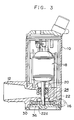
- FIG.3 shows a sectional schematic illustration taken along line 3 - 3 of FIG. 2.
- the washer pump employed in the present embodiment is formed with an opening for fluid intake, i.e., an intake hole 12 shown in an open state and connected to an unillustrated washer fluid supply tank, at the center of a side wall of a housing 10 formed in a substantially cylindrical fashion.
- the washer pump is also provided with an outlet 16 connected to nozzles 52, 54 via an arrangement of piping including, for example, hoses 50, etc., at the lower part of the side wall thereof.
- a rotor of a motor 18 is contained in the upper part of the housing 10, while a pump chamber 24 accommodating an impeller 22 is formed in the lower part thereof.
- the distal end of a rotary shaft of the motor 18 is attached to the central portion of the impeller 22. Washer fluid, which is to be supplied to the pump chamber 24 from an unillustrated tank via the inlet 12, is discharged from the outlet 16 at given pressure.
- FIG. 4 shows an enlarged cross-sectional view of the pump chamber 24 used for the washer pump.
- the pump chamber 24 employed in the present embodiment is formed between the housing 10 and a cap 26 by welding the cap 26 onto the bottom of the housing 10 defining an upper half portion of the pump chamber 24 which contains the impeller 22.
- the impeller 22 is housed within a circular groove 24A formed in the bottom of the housing 10 and the circular groove 24A is then closed by moans of the cap 26, whereby the principal part of the pump chamber 24 is formed.
- the impeller 22 is formed with a hole 22c, which is brought into engagement with the rotary shaft 20 of the motor, in the center of a circular disc 22a.
- a plurality of grooves 22b are formed in the impeller 22 at regular intervals along the outer periphery. These grooves 22b are formed in the front and reverse sides of the impeller 22 so as to partially reduce the thickness of the impeller 22.
- the impeller 22 according to the present invention is formed with supplemental vanes 22d providing forcible fluid movement at a position adjacent to the central portion of the impeller 22.
- four supplemental vanes in total are provided in a substantially symmetrical form and in a radial direction of the impeller 22 with the engagement hole 22c interposed therebetween.
- FIG. 1 shows an exploded view of the pump chamber portion shown in FIG. 4.
- FIG. 1(A) depicts a housing portion formed with the upper half part of the pump chamber 24.
- FIG. 1(B) is a bottom view of the top face 28 of the pump chamber 24.
- FIG. 1(C) is a cross-sectional view taken along the shaft center of the impeller.
- FIG. 1(D) is a cross-sectional view showing the structure which is principally located adjacent to the top of the cap 26.
- a flow channel 30 through which washer fluid flows along the outer periphery of the circular groove 24A is formed within the pump chamber 24.
- the flow channel 30 employed in the present embodiment is a concave groove 32, whose length is in the form of a C and is formed along the outer periphery of the top face of the pump chamber 24, and a concave groove 34 formed onto the cap 26 opposite the concave groove 32.
- a circular and concave supplemental space 36 for fluid movement, which defines spacing allowing the supplemental vanes 22d of the impeller 22 to rotate.
- a partition wall 38 whose length is in the form of a ring, is formed between the supplemental space 36 and the concave groove 32.
- the supplemental space 36 communicates with the end of the flow channel 30 through a concave-shaped fluid flow path 40, which is formed by cutting part of the partition wall 38.
- the cap 26 has a bottom face 26B for the pump chamber, which is formed in the inner side surrounded by the concave groove 34. Also formed in the center of the bottom face 26B of the pump chamber 24 is a groove 26C for holding the distal end of the rotary shaft 20 of the motor.
- the spaces between the impeller 22 and the top face of the partition wall 38 and that between the bottom face 26B of the pump chamber and the impeller 22 are narrow.
- the grooves 22b formed in the impeller 22 are such that they are rotated and driven along the flow channel 30 within the pump chamber 24.
- a hole 36A, through which the rotary shaft 20 of the motor extends, is formed in the central portion of the supplemental space 36.
- a spacing is defined between the inner peripheral wall of the hole 36A and the rotary shaft 20 of the motor and is used as a passage through which washer fluid from the inlet 14 is delivered to the supplemental space 36.
- the features of the present invention reside in that the washer fluid delivered to the intake hole 12 is supplied to the supplemental space 36 in the pump chamber 24 via an inlet 14 and the pressure exerted on the washer fluid is increased owing to the rotation of the supplemental vanes of the impeller 22 so as to be forced into one end of the flow channel 30 via the fluid flow path 40.
- the washer fluid which has been forced into the flow channel 30, is gradually subjected to an increase in pressure together with the rotation of the impeller 22 owing to the grooves 22b formed in the outer periphery of the impeller 22.
- the washer fluid is then discharged under full pressure from an outlet 16 provided at the other end of the flow channel 30.
- an air vent 42 for providing a discharge of air is formed in the supplemental space 36, the fluid flow path 40 or the flow channel 30.
- the air vent 42 is provided so it communicates between the end of the flow channel 30 and the inlet 14.
- the air vent 42 is formed in the fluid flow path 40 and in a portion adjacent to the fluid flow path 40 connected to the flow channel 30.
- the air vent 42 is a through-hole whose free end makes an opening on the upstream side of the hole 36A formed in the inlet 14 and whose axis is defined as a straight line.
- the diameter of the air vent 42 should be 2 mm or more to effectively discharge air from the air vent 42.
- the washer fluid from the inlet 14 is introduced into the pump chamber 24 as an alternative to the use of the hole 36A, thereby overcoming a possible problem.
- FIGS. 6(A) and 6(B) show the washer fluid flow from the input of the fluid into the inlet to the discharge of the same from the outlet 16.
- the washer fluid is introduced from the central portion of the pump chamber 24 into the supplemental space 36 thereof via the intake hole 12 and the inlet 14 as shown in FIG. 6(A) (as indicated by the arrow A).
- the washer fluid is introduced into the supplemental space 36 as referred to above, some of the residual air which exists inside the pump chamber 24 is discharged on the side of the inlet 14 via the air vent 42 (as indicated by the arrow B), so that the washer fluid with air contained therein can surround the supplemental vanes 22d of the impeller 22 or enter part of the flow channel 30 in which air is trapped.
- the flow channel 30 is fully filled with the washer fluid within the supplemental space 36 via the fluid flow path 40 in accordance with the rotary motion of the supplemental vanes 22d which are driven correspondingly, as shown in FIG. 6(B) (as indicated by the arrow C).
- the washer fluid with which the flow channel 30 is filled is gradually pressurized by rotatably driving the impeller 22 so as to be delivered at full pressure from the outlet 16 provided on the side of the other end of the flow channel 30 (as indicated by the arrow D).
- the residual air which exists within the pump chamber 24 and the piping arrangement, can easily be extruded from the nozzles 52, 54 with fully pressurized washer fluid in the above-described manner, without risk of the air lock problems which can occur in the conventional example.
- the supplemental vanes 22d may also be designed in an arbitrary form and the number of the supplemental vanes 22d may also be increased or decreased as needed.
Landscapes
- Engineering & Computer Science (AREA)
- Mechanical Engineering (AREA)
- General Engineering & Computer Science (AREA)
- Water Supply & Treatment (AREA)
- Structures Of Non-Positive Displacement Pumps (AREA)
Description
- The present invention relates to a windscreen washer pump, and particularly to a single outlet-type washer pump for use with a vehicle, which serves to supply washer fluid to the windscreen.
- One type of washer fluid washer pump heretofore used for vehicles is a Westco rotary pump. With this type of pump, washer fluid can be supplied to, for example, a front glass, rear glass or the like at full pressure because washer fluid within a pump chamber can be fully pressurized for spraying it from an outlet.
- FIGS. 7 and 8 show a conventional Westco rotary washer pump.
- This pump has a
pump chamber 24 with aflow channel 30 defined along the outer periphery thereof, and anrotatable impeller 22 within thepump chamber 24. When theimpeller 22 is rotated and driven in a direction indicated by the arrow of FIG. 7, the washer fluid supplied from aninlet 14 is fully pressurized within theflow channel 30 and expelled from anoutlet 16. - As shown in FIG. 8, the
outlet 16 of the washer pump is guided tovarious spray nozzles hoses 50, a three-way joint 60, etc. The illustratednozzles check valves 56, 58 are provided at intermediate points of the piping arrangement. - In such a washer system, when the washer switch is operated by the user, the pump is driven and the washer fluid within a tank is sprayed through the
front nozzles hoses 50 in the piping arrangement fills with air. - At this point the user must refill the washer tank before using the washer system.
- The conventional washer system is however accompanied by the problem that the fluid does not enter the
pump chamber 24 because of the residual air in thehoses 50 and therefore fails to self-prime and become functional again, even when theimpeller 22 provided within the pump is rotated and driven. - In particular, in the above-described washer system, it is hard to remove or expel air which exists within the piping arrangement, especially air within the
hoses 50 and thepump chamber 24 because of check the valves (56,58) within the piping arrangement. Accordingly, ordinary users cannot easily solve the problem. - It is already known from FR-A-2 462 594 to provide a windscreen washer pump having supplemental space for eliminating bubbles appearing in the pump chamber. However, this supplemental space is located directly above the pump chamber so that air bubbles from the expulsion area are collected in that space by gravity separation and are eliminated in a way not described. Therefore, also this known windscreen washer pump suffers from the before mentioned disadvantages.
- Further, GB-A-2 134 598 discloses a fuel pump for internal combustion engines, whose object is to separate gas bubbles (cavitation) from the fuel feed stream and is therefore quite different.
- With the foregoing problem in view, it is therefore an object of the present invention to provide a washer pump for use with a vehicle, which can successively supply washer fluid, even after the tank has run dry and been refilled, without the problem of air in the piping.
- In the present invention, a windscreen washer pump having an inlet and an outlet suitable for use with washer fluid, wherein said washer fluid supplied from said inlet is forced under pressure from said outlet, comprising a pump chamber, an impeller provided within said pump chamber, a motor for rotating said impeller, a flow channel disposed at an inner peripheral portion of said pump chamber, and a supplemental space for eliminating air appearing in said pump chamber (windscreen washer pump of the type disclosed in FR-A-2 462 594), is characterized in that the supplemental space is disposed between said impeller and said inlet; a plurality of supplemental vanes are provided within said supplemental space and are responsive to the driving force of said motor so as to be rotated together with said impeller, said plurality of supplemental vanes apply pressure to air in said supplemental space and serve to force-feed under pressure said washer fluid supplied from said inlet to said impeller thus ensuring delivery of said washer fluid from said impeller when air is present in said pump chamber; and an air vent is provided between said inlet and said pump chamber for expelling air from said pump chamber to said inlet.
- The supplemental vanes are provided as well as provision of an impeller designed to forcibly feed with pressure the washer fluid by vortical flow. They are provided on the upstream side of the impeller and serve to pressurize air and washer fluid with the air included therein so as to deliver the same to the impeller provided within the pump chamber. Accordingly, even when air is included in the pump chamber, the air or the mixture of the air and the washer fluid is forcibly introduced into the impeller, thereby ensuring that the impeller is selfpriming. As the air vent for expelling air is provided between the pump chamber and the inlet, the air is discharged from the pump chamber by means of the supplemental vanes, so that the washer fluid is fed into the pump chamber.
- The above and other objects, features and advantages of the present invention will become apparent from the following description and the appended claims, taken in conjunction with the accompanying drawings in which a preferred embodiment of the present invention is illustrated in the following example.
-
- FIG. 1(A) is a cross-sectional view showing the structure adjacent to a pump chamber formed in a pump according to one embodiment of the present invention;
- FIG. 1(B) is a bottom view of the structure shown in FIG. 1(A);
- FIG. 1(C) is a cross-sectional view showing an impeller and taken along the axial center thereof;
- FIG. 1(D) is a cross-sectional view showing a cap corresponding to the structure depicted in FIG. 1(A);
- FIG. 2 is a side view showing a pump according to an embodiment of the present invention;
- FIG. 3 is a cross-sectional view depicting the pump of FIG. 2 according to an embodiment of the present invention;
- FIG. 4 is an enlarged cross-sectional view showing part of the pump shown in FIG. 3;
- FIG. 5 is a plan view depicting an impeller;
- FIG. 6(A) is a cross-sectional view of the structure with fluid flow shown therein, which is similar to that illustrated in FIG. 1(A);
- FIG. 6(B) is a cross-sectional view of the structure with fluid flow shown therein, which is similar to that depicted in FIG. 1(B);
- FIG. 7 is a plan view in section showing a conventional pump chamber; and
- FIG. 8 is a schematic view for describing the piping arrangement of a conventional pump chamber.
- A preferred embodiment of the present invention will now be described in detail with reference to the accompanying drawings.
- FIG. 2 illustrates the complete exterior of a washer fluid washer pump for a vehicle, to which the present invention is applied. FIG.3 shows a sectional schematic illustration taken along line 3 - 3 of FIG. 2.
- The washer pump employed in the present embodiment is formed with an opening for fluid intake, i.e., an
intake hole 12 shown in an open state and connected to an unillustrated washer fluid supply tank, at the center of a side wall of ahousing 10 formed in a substantially cylindrical fashion. In addition, the washer pump is also provided with anoutlet 16 connected tonozzles hoses 50, etc., at the lower part of the side wall thereof. - As shown in FIG. 3, a rotor of a
motor 18 is contained in the upper part of thehousing 10, while apump chamber 24 accommodating animpeller 22 is formed in the lower part thereof. In addition, the distal end of a rotary shaft of themotor 18 is attached to the central portion of theimpeller 22. Washer fluid, which is to be supplied to thepump chamber 24 from an unillustrated tank via theinlet 12, is discharged from theoutlet 16 at given pressure. - FIG. 4 shows an enlarged cross-sectional view of the
pump chamber 24 used for the washer pump. - The
pump chamber 24 employed in the present embodiment is formed between thehousing 10 and acap 26 by welding thecap 26 onto the bottom of thehousing 10 defining an upper half portion of thepump chamber 24 which contains theimpeller 22. Theimpeller 22 is housed within acircular groove 24A formed in the bottom of thehousing 10 and thecircular groove 24A is then closed by moans of thecap 26, whereby the principal part of thepump chamber 24 is formed. - As shown in FIG. 5, the
impeller 22 is formed with ahole 22c, which is brought into engagement with therotary shaft 20 of the motor, in the center of acircular disc 22a. In addition, a plurality ofgrooves 22b are formed in theimpeller 22 at regular intervals along the outer periphery. Thesegrooves 22b are formed in the front and reverse sides of theimpeller 22 so as to partially reduce the thickness of theimpeller 22. Furthermore, theimpeller 22 according to the present invention is formed withsupplemental vanes 22d providing forcible fluid movement at a position adjacent to the central portion of theimpeller 22. In the illustrated embodiment, four supplemental vanes in total are provided in a substantially symmetrical form and in a radial direction of theimpeller 22 with theengagement hole 22c interposed therebetween. - FIG. 1 shows an exploded view of the pump chamber portion shown in FIG. 4. In the same drawing, FIG. 1(A) depicts a housing portion formed with the upper half part of the
pump chamber 24. FIG. 1(B) is a bottom view of thetop face 28 of thepump chamber 24. FIG. 1(C) is a cross-sectional view taken along the shaft center of the impeller. FIG. 1(D) is a cross-sectional view showing the structure which is principally located adjacent to the top of thecap 26. - As shown in the same drawing, a
flow channel 30 through which washer fluid flows along the outer periphery of thecircular groove 24A is formed within thepump chamber 24. Theflow channel 30 employed in the present embodiment is aconcave groove 32, whose length is in the form of a C and is formed along the outer periphery of the top face of thepump chamber 24, and aconcave groove 34 formed onto thecap 26 opposite theconcave groove 32. - Also defined in the top face of the
pump chamber 24 is a circular and concavesupplemental space 36 for fluid movement, which defines spacing allowing thesupplemental vanes 22d of theimpeller 22 to rotate. Apartition wall 38 whose length is in the form of a ring, is formed between thesupplemental space 36 and theconcave groove 32. In addition, thesupplemental space 36 communicates with the end of theflow channel 30 through a concave-shapedfluid flow path 40, which is formed by cutting part of thepartition wall 38. - As shown in FIG. 1(D), the
cap 26 has abottom face 26B for the pump chamber, which is formed in the inner side surrounded by theconcave groove 34. Also formed in the center of thebottom face 26B of thepump chamber 24 is agroove 26C for holding the distal end of therotary shaft 20 of the motor. - As also depicted in FIG. 4, the spaces between the
impeller 22 and the top face of thepartition wall 38 and that between thebottom face 26B of the pump chamber and theimpeller 22 are narrow. Thegrooves 22b formed in theimpeller 22 are such that they are rotated and driven along theflow channel 30 within thepump chamber 24. - Incidentally, as illustrated in FIG. 4, a
hole 36A, through which therotary shaft 20 of the motor extends, is formed in the central portion of thesupplemental space 36. However, a spacing is defined between the inner peripheral wall of thehole 36A and therotary shaft 20 of the motor and is used as a passage through which washer fluid from theinlet 14 is delivered to thesupplemental space 36. - The features of the present invention reside in that the washer fluid delivered to the
intake hole 12 is supplied to thesupplemental space 36 in thepump chamber 24 via aninlet 14 and the pressure exerted on the washer fluid is increased owing to the rotation of the supplemental vanes of theimpeller 22 so as to be forced into one end of theflow channel 30 via thefluid flow path 40. - The washer fluid, which has been forced into the
flow channel 30, is gradually subjected to an increase in pressure together with the rotation of theimpeller 22 owing to thegrooves 22b formed in the outer periphery of theimpeller 22. The washer fluid is then discharged under full pressure from anoutlet 16 provided at the other end of theflow channel 30. - It is thus possible to force washer fluid into the
flow channel 30 formed along a locus face developed by the rotation of thegrooves 22b in theimpeller 22 and hence to prevent air locks occurring, even when residual air exists in thepump chamber 24. - One other feature of the present invention resides in that an
air vent 42 for providing a discharge of air is formed in thesupplemental space 36, thefluid flow path 40 or theflow channel 30. In the present embodiment, theair vent 42 is provided so it communicates between the end of theflow channel 30 and theinlet 14. - Thus, the forcing of washer fluid into the
flow channel 30, the discharge of the residual air from thepump chamber 24 or the like can be effected simultaneously, so that any problem due to air is solved rapidly and effectively. - As indicated obliquely by the broken line in FIG. 1(B) in particular, it is preferable that the
air vent 42 is formed in thefluid flow path 40 and in a portion adjacent to thefluid flow path 40 connected to theflow channel 30. As shown in FIG. 4, theair vent 42 is a through-hole whose free end makes an opening on the upstream side of thehole 36A formed in theinlet 14 and whose axis is defined as a straight line. - The diameter of the
air vent 42 should be 2 mm or more to effectively discharge air from theair vent 42. When theair vent 42 diameter is large, the washer fluid from theinlet 14 is introduced into thepump chamber 24 as an alternative to the use of thehole 36A, thereby overcoming a possible problem. - FIGS. 6(A) and 6(B) show the washer fluid flow from the input of the fluid into the inlet to the discharge of the same from the
outlet 16. - In other words, when the unillustrated empty washer fluid supply tank is refilled, but the
pump chamber 24 and piping arrangement are dry, the washer fluid is introduced from the central portion of thepump chamber 24 into thesupplemental space 36 thereof via theintake hole 12 and theinlet 14 as shown in FIG. 6(A) (as indicated by the arrow A). When the washer fluid is introduced into thesupplemental space 36 as referred to above, some of the residual air which exists inside thepump chamber 24 is discharged on the side of theinlet 14 via the air vent 42 (as indicated by the arrow B), so that the washer fluid with air contained therein can surround thesupplemental vanes 22d of theimpeller 22 or enter part of theflow channel 30 in which air is trapped. - When the washer switch is operated to rotatably drive the
impeller 22 in this state, theflow channel 30 is fully filled with the washer fluid within thesupplemental space 36 via thefluid flow path 40 in accordance with the rotary motion of thesupplemental vanes 22d which are driven correspondingly, as shown in FIG. 6(B) (as indicated by the arrow C). - The washer fluid with which the
flow channel 30 is filled is gradually pressurized by rotatably driving theimpeller 22 so as to be delivered at full pressure from theoutlet 16 provided on the side of the other end of the flow channel 30 (as indicated by the arrow D). - According to the present invention, the residual air, which exists within the
pump chamber 24 and the piping arrangement, can easily be extruded from thenozzles - Incidentally, the present invention is not necessarily limited to the above-described embodiment and many changes and modifications can be made thereto without departing from the spirit and scope of the invention as set forth herein, provided the invention remains that one defined by the claims.
- In the above-described embodiment, a description has been made in the case where, for example, the four
supplemental vanes 22d are mounted on theimpeller 22 symmetrically with respect to the center of rotation of the shaft. However, the present invention is not necessarily limited to this embodiment. For example, thesupplemental vanes 22d may also be designed in an arbitrary form and the number of thesupplemental vanes 22d may also be increased or decreased as needed. - A description has been made of the Westco rotary pump by way of an illustrative example in the above-described embodiment. However, needless to say, pumps other than the Westco rotary pump can be adapted as needed.
Claims (11)
- A windscreen washer pump having an inlet (14) and an outlet (16) suitable for use with washer fluid, wherein said washer fluid supplied from said inlet (14) is forced under pressure from said outlet (16), comprising a pump chamber (24), an impeller (22) provided within said pump chamber (24), a motor (18) for rotating said impeller (22), a flow channel (30) disposed at an inner peripheral portion of said pump chamber (24), and a supplemental space (36) for eliminating air appearing in said pump chamber (24), characterized in that the supplemental space (36) is disposed between said impeller (22) and said inlet (14); a plurality of supplemental vanes (22d) are provided within said supplemental space (36) and are responsive to the driving force of said motor (18) so as to be rotated together with said impeller (22), said plurality of supplemental vanes (22d) apply pressure to air in said supplemental space (36) and serve to force-feed under pressure said washer fluid supplied from said inlet (14) to said impeller (22) thus ensuring delivery of said washer fluid from said impeller (22) when air is present in said pump chamber (24); and an air vent (42) is provided between said inlet (14) and said pump chamber (24) for expelling air from said pump chamber (24) to said inlet (14).
- A windscreen washer pump according to claim 1, wherein said air vent (42) is formed to communicate with one of said supplemental space (36), said flow channel (30) and a forced fluid flow path (40).
- A windscreen washer pump according to claim 1, wherein said air vent (42) is formed to communicate with said supplemental space (36).
- A windscreen washer pump according to claim 3, wherein said air vent (42) is formed at a side of an outer peripheral portion of said plurality of supplemental vanes (22d) disposed in said supplemental space (36).
- A windscreen washer pump according to claim 1, wherein said plurality of supplemental vanes (22d) is disposed coaxially with said impeller (22).
- A windscreen washer pump according to claim 1, wherein said plurality of supplemental vanes (22d) are fixedly secured integrally with said impeller (22).
- A windscreen washer pump according to claim 1, wherein said plurality of supplemental vanes (22d) comprises a plurality of plate members disposed in radial direction of said impeller (22).
- A windscreen washer pump according to claim 1, wherein said plurality of supplemental vanes (22d) are disposed around a rotary shaft of said motor (18) secured to said impeller (22).
- A windscreen washer pump according to claim 1, wherein a partition wall (38) is provided around said impeller (22) and a cut-way portion is formed on part of said partition wall (38) to provide a forced-fluid flow path (40) communicating with said flow channel (30).
- A windscreen washer pump according to claim 9, said air vent (42) is provided through said partition wall (38) to communicate between said pump chamber (24) and said inlet (14) through said forced-fluid flow path (40).
- A windscreen washer pump according to claim 1, further comprising a housing (10) and a hole (36A) which is formed for causing said washer fluid delivered from said inlet (14) to pass through the outer periphery of the rotary shaft of said motor (18) along the rotary shaft thereof and said plurality of supplemental vanes (22d) radially disposed around the rotary shaft of said motor (18) is provided in an opposing relationship to the flow of said washer fluid from said hole (36A), and also serve to forcibly feed under pressure said washer fluid in the radial direction so as to be delivered to said flow channel (30).
Applications Claiming Priority (2)
| Application Number | Priority Date | Filing Date | Title |
|---|---|---|---|
| JP90036/89 | 1989-04-10 | ||
| JP1989090036U JPH0330596U (en) | 1989-07-31 | 1989-07-31 |
Publications (3)
| Publication Number | Publication Date |
|---|---|
| EP0411428A2 EP0411428A2 (en) | 1991-02-06 |
| EP0411428A3 EP0411428A3 (en) | 1991-08-14 |
| EP0411428B1 true EP0411428B1 (en) | 1995-01-11 |
Family
ID=13987430
Family Applications (1)
| Application Number | Title | Priority Date | Filing Date |
|---|---|---|---|
| EP90114107A Expired - Lifetime EP0411428B1 (en) | 1989-07-31 | 1990-07-24 | Windscreen washer pump for vehicle |
Country Status (4)
| Country | Link |
|---|---|
| US (1) | US5080554A (en) |
| EP (1) | EP0411428B1 (en) |
| JP (1) | JPH0330596U (en) |
| DE (1) | DE69015918T2 (en) |
Families Citing this family (16)
| Publication number | Priority date | Publication date | Assignee | Title |
|---|---|---|---|---|
| GB2239050B (en) * | 1989-11-17 | 1993-10-06 | Mitsubishi Electric Corp | Circumferential flow type fuel pump |
| DE4221184A1 (en) * | 1992-06-27 | 1994-01-05 | Bosch Gmbh Robert | Fuel delivery pump for vehicle IC engine - uses space between impeller and delivery channel to control direction of flow |
| DE4239488C2 (en) * | 1992-11-25 | 2001-06-28 | Bosch Gmbh Robert | Unit for delivering fuel from a storage tank to the internal combustion engine of a motor vehicle |
| US5284417A (en) * | 1993-06-07 | 1994-02-08 | Ford Motor Company | Automotive fuel pump with regenerative turbine and long curved vapor channel |
| DE4432224A1 (en) * | 1994-09-10 | 1996-03-14 | Elektra Beckum Ag | Method to improve suction efficiency of flow demand pump |
| US5580213A (en) * | 1995-12-13 | 1996-12-03 | General Motors Corporation | Electric fuel pump for motor vehicle |
| DE19615322A1 (en) | 1996-04-18 | 1997-10-23 | Vdo Schindling | Peripheral pump |
| KR100217618B1 (en) * | 1996-12-12 | 1999-09-01 | 정몽규 | Washer liquid injection position adjusting device |
| US6227819B1 (en) | 1999-03-29 | 2001-05-08 | Walbro Corporation | Fuel pumping assembly |
| US6231318B1 (en) | 1999-03-29 | 2001-05-15 | Walbro Corporation | In-take fuel pump reservoir |
| DE10019913A1 (en) * | 2000-04-20 | 2001-10-25 | Mannesmann Vdo Ag | Pump esp. fuel pump or windscreen washer fluid pump for motor vehicles has driven shaft and rotor, one or both with elements for correct positioning |
| JP3720682B2 (en) * | 2000-06-29 | 2005-11-30 | 株式会社ミツバ | Pump motor for vehicles |
| USD491577S1 (en) | 2002-09-06 | 2004-06-15 | Jidosha Denki Kogyo Co., Ltd. | Washer pump |
| US9249806B2 (en) | 2011-02-04 | 2016-02-02 | Ti Group Automotive Systems, L.L.C. | Impeller and fluid pump |
| CN104218739A (en) * | 2013-06-03 | 2014-12-17 | 德昌电机(深圳)有限公司 | Washing pump for automobile windscreen wipers |
| DK3292028T3 (en) * | 2015-05-07 | 2021-06-07 | Jetwipe 2017 Aps | Wiper-free cleaning system for transparent surfaces using air jets |
Citations (1)
| Publication number | Priority date | Publication date | Assignee | Title |
|---|---|---|---|---|
| EP0411431A2 (en) * | 1989-07-31 | 1991-02-06 | Asmo Co., Ltd. | Windscreen washer pump for vehicle |
Family Cites Families (14)
| Publication number | Priority date | Publication date | Assignee | Title |
|---|---|---|---|---|
| DE375042C (en) * | 1923-05-04 | Fritz Schnecko | Fire extinguishing pump with ventilation pump | |
| US1652659A (en) * | 1925-03-09 | 1927-12-13 | Roy A Oppenheim | Pump |
| US2982986A (en) * | 1956-09-19 | 1961-05-09 | Gen Electric | Vacuum cleaner with improved fan arrangement |
| DE1806195A1 (en) * | 1968-10-31 | 1970-07-23 | Eisele Soehne Franz | Vertical slurry pump |
| JPS514603A (en) * | 1974-07-02 | 1976-01-14 | Mabuchi Motor Co | |
| ES244882Y (en) * | 1979-07-30 | 1984-02-16 | Transpar Iberica Sa | ELECTRIC WINDSHIELD WASHER PUMP |
| DE3014425C2 (en) * | 1980-04-15 | 1986-06-12 | Friedrich 8541 Röttenbach Schweinfurter | Side channel pump |
| DE3303352A1 (en) * | 1983-02-02 | 1984-08-02 | Robert Bosch Gmbh, 7000 Stuttgart | AGGREGATE FOR PROMOTING FUEL, PREFERABLY FROM A STORAGE TANK FOR THE INTERNAL COMBUSTION ENGINE, ESPECIALLY A MOTOR VEHICLE |
| DE3303460A1 (en) * | 1983-02-02 | 1984-08-02 | Friedrich 8541 Röttenbach Schweinfurter | SELF-PRIMING SIDE CHANNEL PUMP |
| JPS60138297A (en) * | 1983-12-27 | 1985-07-22 | Toyota Motor Corp | Circumferential flow type liquid pump |
| DE3427112A1 (en) * | 1984-07-23 | 1986-01-23 | Friedrich 8541 Röttenbach Schweinfurter | SIDE CHANNEL PUMP WITH FORCE COMPENSATION |
| ES2004307A6 (en) * | 1987-06-19 | 1988-12-16 | Weber Espana Sa | Improvements in the design of fuel feed pumps |
| JPH01176792U (en) * | 1988-06-03 | 1989-12-18 | ||
| US5020969A (en) * | 1988-09-28 | 1991-06-04 | Hitachi, Ltd. | Turbo vacuum pump |
-
1989
- 1989-07-31 JP JP1989090036U patent/JPH0330596U/ja active Pending
-
1990
- 1990-07-24 DE DE69015918T patent/DE69015918T2/en not_active Expired - Fee Related
- 1990-07-24 EP EP90114107A patent/EP0411428B1/en not_active Expired - Lifetime
- 1990-07-26 US US07/557,799 patent/US5080554A/en not_active Expired - Fee Related
Patent Citations (1)
| Publication number | Priority date | Publication date | Assignee | Title |
|---|---|---|---|---|
| EP0411431A2 (en) * | 1989-07-31 | 1991-02-06 | Asmo Co., Ltd. | Windscreen washer pump for vehicle |
Also Published As
| Publication number | Publication date |
|---|---|
| EP0411428A3 (en) | 1991-08-14 |
| US5080554A (en) | 1992-01-14 |
| DE69015918T2 (en) | 1995-08-31 |
| JPH0330596U (en) | 1991-03-26 |
| DE69015918D1 (en) | 1995-02-23 |
| EP0411428A2 (en) | 1991-02-06 |
Similar Documents
| Publication | Publication Date | Title |
|---|---|---|
| EP0411428B1 (en) | Windscreen washer pump for vehicle | |
| CN1063681C (en) | Dual in-line trigger sprayer | |
| JP3164228B2 (en) | Dispenser | |
| US4331295A (en) | Windshield washer | |
| AU736268B2 (en) | Media dispenser | |
| KR20040100930A (en) | Dual sprayer with external mixing chamber | |
| KR100321093B1 (en) | Dispensing cartridge | |
| JPH0688619B2 (en) | Mechanically pressurized aerosol dispenser | |
| JPH11189282A (en) | System and method for one-way spray/aerosol tip | |
| WO1990003227A1 (en) | Foam-off nozzle assembly with barrel screen insert for use in a trigger sprayer | |
| EP0411431B1 (en) | Windscreen washer pump for vehicle | |
| GB2326833A (en) | Plural color painting apparatus | |
| KR910012535A (en) | Liquid pump with degassing function | |
| EP0779433B1 (en) | Electric fuel pump for motor vehicle | |
| JPH05104038A (en) | Nozzle for discharging medium | |
| CN212383924U (en) | Trigger spray pump | |
| WO1992022364A1 (en) | Water gun for ejecting continuous stream of water | |
| US6102255A (en) | Invertible dispensing means for spray containers | |
| US6001177A (en) | Golf ball paint delivery system | |
| JPS6270678A (en) | Diaphragm pump | |
| CN106224239A (en) | Pump assembly and the compressor assembly with it | |
| US4631003A (en) | Fluid medium compressor and user apparatus | |
| JP2764217B2 (en) | Jet pump | |
| US4697993A (en) | Fluid medium compressor and user apparatus | |
| US5372308A (en) | Washing system, especially for windshields of a motor vehicle |
Legal Events
| Date | Code | Title | Description |
|---|---|---|---|
| PUAI | Public reference made under article 153(3) epc to a published international application that has entered the european phase |
Free format text: ORIGINAL CODE: 0009012 |
|
| AK | Designated contracting states |
Kind code of ref document: A2 Designated state(s): DE GB |
|
| PUAL | Search report despatched |
Free format text: ORIGINAL CODE: 0009013 |
|
| AK | Designated contracting states |
Kind code of ref document: A3 Designated state(s): DE GB |
|
| 17P | Request for examination filed |
Effective date: 19920115 |
|
| 17Q | First examination report despatched |
Effective date: 19930401 |
|
| GRAA | (expected) grant |
Free format text: ORIGINAL CODE: 0009210 |
|
| AK | Designated contracting states |
Kind code of ref document: B1 Designated state(s): DE GB |
|
| REF | Corresponds to: |
Ref document number: 69015918 Country of ref document: DE Date of ref document: 19950223 |
|
| PG25 | Lapsed in a contracting state [announced via postgrant information from national office to epo] |
Ref country code: GB Effective date: 19950724 |
|
| PLBE | No opposition filed within time limit |
Free format text: ORIGINAL CODE: 0009261 |
|
| 26N | No opposition filed | ||
| GBPC | Gb: european patent ceased through non-payment of renewal fee |
Effective date: 19950724 |
|
| PG25 | Lapsed in a contracting state [announced via postgrant information from national office to epo] |
Ref country code: DE Effective date: 19960402 |
|
| PLAA | Information modified related to event that no opposition was filed |
Free format text: ORIGINAL CODE: 0009299DELT |
|
| PLBE | No opposition filed within time limit |
Free format text: ORIGINAL CODE: 0009261 |
|
| STAA | Information on the status of an ep patent application or granted ep patent |
Free format text: STATUS: NO OPPOSITION FILED WITHIN TIME LIMIT |
|
| 26N | No opposition filed |