EP0390230B1 - Procédé et appareil pour assembler une pluralité d'articles - Google Patents
Procédé et appareil pour assembler une pluralité d'articles Download PDFInfo
- Publication number
- EP0390230B1 EP0390230B1 EP90110671A EP90110671A EP0390230B1 EP 0390230 B1 EP0390230 B1 EP 0390230B1 EP 90110671 A EP90110671 A EP 90110671A EP 90110671 A EP90110671 A EP 90110671A EP 0390230 B1 EP0390230 B1 EP 0390230B1
- Authority
- EP
- European Patent Office
- Prior art keywords
- row
- articles
- station
- gap
- tape
- Prior art date
- Legal status (The legal status is an assumption and is not a legal conclusion. Google has not performed a legal analysis and makes no representation as to the accuracy of the status listed.)
- Expired - Lifetime
Links
- 238000000034 method Methods 0.000 title claims description 4
- 239000002390 adhesive tape Substances 0.000 description 13
- 239000000853 adhesive Substances 0.000 description 11
- 230000001070 adhesive effect Effects 0.000 description 11
- 230000006835 compression Effects 0.000 description 4
- 238000007906 compression Methods 0.000 description 4
- 239000004820 Pressure-sensitive adhesive Substances 0.000 description 3
- 230000007246 mechanism Effects 0.000 description 3
- 229910000639 Spring steel Inorganic materials 0.000 description 2
- 229910000831 Steel Inorganic materials 0.000 description 1
- 230000003190 augmentative effect Effects 0.000 description 1
- 238000007664 blowing Methods 0.000 description 1
- 238000000576 coating method Methods 0.000 description 1
- 238000009833 condensation Methods 0.000 description 1
- 230000005494 condensation Effects 0.000 description 1
- 230000001419 dependent effect Effects 0.000 description 1
- 230000000694 effects Effects 0.000 description 1
- 229920002457 flexible plastic Polymers 0.000 description 1
- 238000010030 laminating Methods 0.000 description 1
- 239000007788 liquid Substances 0.000 description 1
- 239000012945 sealing adhesive Substances 0.000 description 1
- 239000007787 solid Substances 0.000 description 1
- 239000010959 steel Substances 0.000 description 1
Images


Classifications
-
- B—PERFORMING OPERATIONS; TRANSPORTING
- B65—CONVEYING; PACKING; STORING; HANDLING THIN OR FILAMENTARY MATERIAL
- B65B—MACHINES, APPARATUS OR DEVICES FOR, OR METHODS OF, PACKAGING ARTICLES OR MATERIALS; UNPACKING
- B65B17/00—Other machines, apparatus, or methods for packaging articles or materials
- B65B17/02—Joining articles, e.g. cans, directly to each other for convenience of storage, transport, or handling
-
- B—PERFORMING OPERATIONS; TRANSPORTING
- B65—CONVEYING; PACKING; STORING; HANDLING THIN OR FILAMENTARY MATERIAL
- B65B—MACHINES, APPARATUS OR DEVICES FOR, OR METHODS OF, PACKAGING ARTICLES OR MATERIALS; UNPACKING
- B65B61/00—Auxiliary devices, not otherwise provided for, for operating on sheets, blanks, webs, binding material, containers or packages
- B65B61/14—Auxiliary devices, not otherwise provided for, for operating on sheets, blanks, webs, binding material, containers or packages for incorporating, or forming and incorporating, handles or suspension means in packages
-
- B—PERFORMING OPERATIONS; TRANSPORTING
- B65—CONVEYING; PACKING; STORING; HANDLING THIN OR FILAMENTARY MATERIAL
- B65D—CONTAINERS FOR STORAGE OR TRANSPORT OF ARTICLES OR MATERIALS, e.g. BAGS, BARRELS, BOTTLES, BOXES, CANS, CARTONS, CRATES, DRUMS, JARS, TANKS, HOPPERS, FORWARDING CONTAINERS; ACCESSORIES, CLOSURES, OR FITTINGS THEREFOR; PACKAGING ELEMENTS; PACKAGES
- B65D71/00—Bundles of articles held together by packaging elements for convenience of storage or transport, e.g. portable segregating carrier for plural receptacles such as beer cans or pop bottles; Bales of material
- B65D71/0085—Packaging elements adhered to the articles, e.g. a carton sheet
-
- Y—GENERAL TAGGING OF NEW TECHNOLOGICAL DEVELOPMENTS; GENERAL TAGGING OF CROSS-SECTIONAL TECHNOLOGIES SPANNING OVER SEVERAL SECTIONS OF THE IPC; TECHNICAL SUBJECTS COVERED BY FORMER USPC CROSS-REFERENCE ART COLLECTIONS [XRACs] AND DIGESTS
- Y10—TECHNICAL SUBJECTS COVERED BY FORMER USPC
- Y10S—TECHNICAL SUBJECTS COVERED BY FORMER USPC CROSS-REFERENCE ART COLLECTIONS [XRACs] AND DIGESTS
- Y10S493/00—Manufacturing container or tube from paper; or other manufacturing from a sheet or web
- Y10S493/901—Rigid container
- Y10S493/909—Rigid container having handle or suspension means
Definitions
- This invention relates to the applying of handles to articles and the taping together of articles.
- British Patent Specification 1383108 discloses an apparatus for use in fitting to a carton a handle consisting of a piece of adhesive tape and a piece of opaque paper adhering to the adhesive side of the middle section of the piece of adhesive tape, which is adhered at both ends to shoulders of the carton.
- the apparatus includes a conveying device for intermittently moving the carton along a path to a handle-applying station, a turntable adjacent the path and intermittently angularly displaceable about a vertical axis, in unison with the intermittent movement of the conveying device, the turntable including suction pads to take up tape around its periphery, a cutting device for cutting off the tape on the turntable to give predetermined lengths forming the handles, extensible press arms within the turntable and distributed in pairs therearound for displacing the ends of the handle pieces off the periphery of the turntable at the above station to press those ends onto the carton, and a stop plate interposable between the turntable and the path, during extension of the press arms, to intercept the middle section of each handle piece to prevent contact of the middle section with the carton to form a gap for receiving the fingers of the purchaser of the carton.
- This system utilizes a bulky and complicated apparatus; it also employs an adhesive handle, which in turn requires a non-adhesive covering at the middle section for grasping by the purchaser. Moreover, the handle can move relative to the plate during attaching of the handle to the carton, so that the handle becomes incorrectly positioned on the carton. Furthermore, the advancing of the carton is interrupted for the attaching of the handle.
- European Patent Specification 0174015 describes a system similar to that just described but with the significant differences that the adhesive handle is applied to an article comprised of two or more packs integrally packaged or wrapped, and that the turntable is replaced by a drum rotating about a horizontal axis parallel to the path of the articles.
- This system again utilizes a bulky and complicated apparatus and employs an adhesive handle requiring a non-adhesive covering.
- the handle can move relative to the plate during attaching and the advancing of the article is interrupted for the attaching of the handle.
- United States Patent 4,238,256 discloses a system that forms a ladder-like tape assembly, applies the assembly to a series of bottles moving spaced-apart along a conveyor with a transverse tape aligned with each bottle, and then severs the side tapes between the bottles and adheres the severed portions thereto to provide flexible bails for the bottles.
- the two side tapes have pressure-sensitive adhesive on their inside surfaces in order to adhere to the bottles and to the outside surfaces of the two end zones of each transverse tape, whilst each transverse tape has pressure-sensitive adhesive at the inside surfaces of its two end zones in order to adhere to its bottle.
- the means for forming the transverse tapes preferably forms them from a pressure - sensitive - adhesive - coated web having a width corresponding to the length of the bails desired, and a second web having a width less than that of the first web.
- Means are included for laminating the second web centrally on the adhesive - coated surface of the first web, as are means for transversely severing the laminate thus formed to provide the bails.
- This system again utilizes a bulky and complicated apparatus and employs an adhesive handle requiring a non-adhesive covering.
- a system of taping together a plurality of liquid-containing, rectangular-section cartons is known in which the packs are fed horizontally to a side-taping station at which the cartons are attached together by automatically applying horizontally along the respective opposite sides of the cartons respective adhesive tapes.
- the apparatus employed includes two reels disposed at respective opposite sides of the path of the cartons and on which respective rolls of adhesive tape are mounted for rotation about respective vertical axes. It also includes two perforating devices at respective opposite sides of the path for perforating the tapes each along a top edge band and a bottom edge band, to enable the cartons to be more easily separated by the purchaser.
- the system thereby produces row-form groups of two or more cartons wherein the cartons of each group are side-taped together.
- Perforating rollers perforate each tape with spaced rows of perforations arranged to be located between adjacent cartons, each fifth row, say, containing more perforations.
- Such means comprises a pressure roller arranged to engage the top surface of the cartons and a cam roller spaced behind the pressure roller by a distance not greater than the distance between alternate cartons.
- the cam roller is formed with a projection and disposed immediately below the cartons to rotate once during the passage of every five cartons, say.
- the projection will engage the underside of every fifth carton and lift the carton to fracture the top and bottom tapes between it and the carton immediately ahead, which is held down by the pressure roller.
- a difficulty with this system is that the cartons in each group should be firmly compressed together to give a solid feel to the article constituted by each group, yet such firm compression of the advancing line of cartons militates against lifting of every fifth carton, say, to fracture the tapes.
- United States Patent 2885839 discloses a banding machine in which a line of quart cartons is fed towards a taping station, and the line of cartons is divided into carton pairs as they approach the taping station.
- a pre-perforated tape whereof the perforations define sections of the tape and whereof each tape section is provided at opposite sides of its opposite end portions with dry self-sealing adhesive coatings.
- the tape itself is used to compress the carton pair together, with two jaws on the one hand, and a looper member, on the other hand, moving in opposite senses around the carton pair to close the loop of tape and to tension the tape around the carton pair.
- Auxiliary tensioning means in the form of a friction pad carried by a slide is also provided.
- the pad At the time when the looper member is approaching to contact a tape portion, the pad is brought into a moderate pressure contact with the tape and is then moved slowly in the direction counter to the path of travel of the containers, the tractional pull of the pad serving to eliminate any slack in the tape wrapped around the containers and even augmenting the tension created by the jaws.
- This machine has the disadvantages that the compression obtained cannot be well pre-defined and that the machine is relatively complicated.
- BE-A-635563 discloses an apparatus for the making of stacks of beer-mats in which the mats in each stack are compressedly held together by adhesive tapes which are applied to opposite side faces of the stack and partially to the end faces of the stack.
- the apparatus includes a conveyor comprised of an endless band comprised of elements articulated together and extending over end rollers. Such elements are formed with pairs of holes.
- the band carries two limiting plates each of which is formed with a pair of depending teeth insertable into any selected pair of holes in the elements, the spacing between the plates determining the length of a stack.
- the band displaces the two plates, with the stack laid horizontally therebetween, through a side-taping station, the leading plate acting via a spring on a compression plate to maintain the stack under compression during its passage through the station.
- the station includes two rollers at respective sides of the band and serving to apply the respective adhesive tapes to the respective opposite side faces of the stack.
- the length of the operating phase of the rollers is controlled by way of respective rods upon which the rollers are mounted and which co-operate with respective electromagnets which, under the control of feelers co-operating with electrical connection systems, control the cutting of the adhesive tapes by means of knives, after the passage of the rear part of the stack.
- the folding of the free ends of the tapes around the end faces of the stack is performed by rollers carried by spring-loaded stirrups disposed at respective opposite sides of the conveyor so as to be turnable about vertical axes.
- a method of attaching together a plurality of articles comprising feeding the articles to a taping station, holding apart from each other, as they advance end-to-end through the taping station, each two adjacent rows of a plurality of end-to -end rows each of at least two articles, so providing a gap between each two adjacent rows, and automatically and adhesively attaching together at said station the articles of each row with tape portions at respective opposite sides of the row, characterized by inserting cutting means into the gap so provided between each two adjacent rows to sever the tape portions at the gap, and folding the severed end zones of the tape portions around their respective article edges and automatically and adhesively attaching those severed end zones to the article faces in the gap.
- apparatus for attaching together a plurality of articles comprising a taping station including attaching means arranged automatically and adhesively to attach together the articles of a row of at least two articles with tape portions at respective opposite sides of said row, while each two adjacent rows of a plurality of end-to-end rows each of at least two articles are advanced end-to-end through the taping station in a spaced-apart condition, characterized in that cutting means is insertable into the gap so provided between each two adjacent rows to sever tape portions at the gap, and means is arranged to fold the severed end zones of the tape portions around their respective row edges and automatically and adhesively to attach these severed end zones to the row faces in the gap.
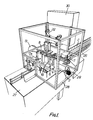
- the filled and top-sealed gable-topped cartons C are advanced along a linear horizontal part of the path of the cartons C through the apparatus, which part lies in the vertical plane V1.
- a row of selectively two or three cartons is pushed laterally by means of either a vertical pusher plate 1 operated by a piston-and-cylinder device 2, or by means of the plate 1 and a vertical pusher plate 3 operated by means of a piston-and-cylinder device 4, until the row of two or three cartons lies in a vertical plane V2 containing a second horizontal linear part of the path of the cartons through the apparatus.
- a frame 6 carries a piston-and-cylinder device 7, the piston rod 7' of which supports at its free end a tape-gripping device 8 including a fixed jaw 9 and a moving jaw 10 formed by the piston of a pneumatic piston-and-cylinder device 11.
- a frame 12 which mounts a reel 13 for rotation about a horizontal axis parallel to the planes V1 and V2 and for carrying a roll of non-adhesive tape T1.
- the frame 12 also mounts a pneumatically operable clamp 14 and a cutting knife 15 vertically reciprocable by means of a pneumatic piston-and-cylinder device 16.
- Fixed to the frame 12 is a pneumatically operable clamp 31 which acts at the middle of the reel 13 to prevent overrun thereof.
- the tape T1 extends from the reel 13 and through the clamp 14.
- the clamps 14 and 31 closed and the device 8 in the position shown in Figures 1 and 2, the device 8 grips the free end of the tape T1 projecting from the clamp 14, the clamps 14 and 31 are then opened, and while the device 2 or the devices 2 and 4 are pushing the row of cartons onto the carrier 5, the device 8 draws the tape T1 off the roll until the position of the device 8 shown in Figure 3 is reached.
- the jaws 9 and 10 as a pair occupy almost half of the width of the tape T1 (see Figure 6).
- the device 8 is thus able to draw the tape T1 over a tape-seizing member in the form of an air pipe 17 which extends beneath the other half of the width of the tape and is there formed in its upper part with perforations 18.
- the pipe 17 extends horizontally in the plane V2 and is supported on a bracket 19 of the carrier 5 in such a manner as to be adjustably displaceable longitudinally for appropriate setting dependent upon whether the handle is to be applied centrally of a group of three cartons, as shown in Figure 6, or centrally of a group of two cartons, as shown in Figure 7.
- the tape-drawing device 7, 8 is adjustable along bars 20 of the frame 6 parallelly to the planes V1 and V2, whilst the frame 12 is bodily adjustable in the same horizontal direction for the same purpose.
- suction is applied to the tube 17, the clamps 14 and 31 are closed, the knife 15 is operated to sever the tape T1, and the device 8 releases the free end zone of the tape. Thereupon the two end zones of the severed length fall down towards the carton row under their own weight.
- Fixed to the bracket 19 is a vertical guide rod 20 serving to guide an encircling end of a horizontal strap 21 to which is fixed the cylinder of a pneumatic piston-and-cylinder device 22 whereof the piston rod 22' is fixed to the bracket 19.
- the device 22 serves to lift and lower a spring steel fork 23 (see Figure 3), or a rigid steel fork 23' with spring steel end zones (see Figure 2), fixed centrally to the strap 21 and provided at its free ends with respective cylindrical pressing projections 24.
- the fork 23 or 23' descends and presses the tape end zones against the respective opposite sides of the carton row.
- the carrier 5 advances through between adhesive-tape-applying rolls 25 of the side-taping device, so as not only to cause the cartons of the row to be taped together, but also to cause the free end zones of the tape handle, the movement of which is restrained by the suction pipe 17 and the fork 23 or 23', to be taped in as well.
- the fork 23 and 23' is raised, the pipe 17 is converted to blowing air out of the perforations 18 and then the carrier 5 is retracted back to the station G, the pipe 17 being thereby withdrawn from beneath the handle H.
- the carrier 5 Upon arrival at the station G, the carrier 5 receives the next row of cartons.
- the cartons C approach the station G upon a conveyor 26 and continue through the apparatus by sliding upon a table 27 which carries a frame 28 with transparent panes defining a chamber with an entry for the cartons to be side-taped and handled, an exit for the taped and handled rows, and an entry for the tape T1.
- a device 29 supplies dehumidified warm air to the chamber, so that condensation onto the walls of the cartons owing to the filling thereinto of cold products is discouraged and the adhesive side tapes T2 adhere more readily thereto.
- the operation of the apparatus is controlled by a programmable controller 30. It is possible to adjust the length of the handle H by adjusting the stroke length of the device 8 and by adjusting the position of the frame 12 perpendicularly to the planes V1 and V2.
- the leading carton is arrested by a stop plate 35 fixed to the table 27, the plate 35 extending perpendicularly to the planes V1 and V2. Extending parallely to those planes is a pusher plate 36 which extends along almost three cartons. Although the three cartons adjacent the pusher plate 36 are shown as being spaced slightly ahead of the cartons on the conveyor 26, they will in practice be touching each other.
- the pusher plate 36 is operated by a pneumatic piston-and-cylinder device 34 so as to move a row of three cartons at a time onto the carrier 5, the respective ends of the row being guided by the plate 35 and a guide plate 38 initially converging towards the plate 35 and also fixed to the table 27. The convergence of the plate 38 causes the three cartons to be squeezed firmly together.
- the carrier 5 has a rear vertical end plate 39, and a front vertical end plate (33 in Figure 6) which is downwardly retractable by means of a pneumatic piston-cylinder device (not shown) carried by the carrier 5.
- the two end plates keep the cartons squeezed firmly together.
- the carrier 5 is horizontally reciprocable in the plane V2 by means of a pneumatic piston-and-cylinder device (not shown).
- the three cartons are prevented from moving beyond the carrier by a vertical plate 41 extending parallely to the plane V2.
- the front vertical end plate (33) is retracted downwards and the carrier 5 withdrawn to its position shown in Figure 8.
- the adhesive tapes T2 applied to respective opposite sides of the row by the rolls 25 prevent the row from returning with the carrier 5.
- the front vertical plate (33) in advancing with the carrier pushes forwards a preceding row of three cartons to which the tapes T2 have already been applied.
- a pair of knives 45 horizontally reciprocable perpendicularly of the rows by piston-and-cylinder devices 46 is shown in almost its innermost condition in Figure 8.
- the knives 45 include respective vertical blades, the cutting edges of which converge to respective points lying in a horizontal plane containing the horizontal centre lines of the respective adhesive tapes T2. These blades initially pierce at the horizontal centre lines and then sever vertically the respective portions of tape bridging the gap between the two adjacent rows.
- the knives 45 Outwardly of the respective cutting edges of the blades, the knives 45 have respective pairs of rounded shoulders, the shoulders of each pair diverging outwardly to a width greater than that of the gap between the two rows, so that, once the blades have severed the portions vertically, the four free tape end zones thus left are pressed by the rounded shoulders around the adjacent vertical edges of the rows, so that the length of tape along each side of a row leaving the apparatus has its end zones wrapped around a front and a rear vertical edge of the row.
- the knives 45 are then withdrawn and the next row of three cartons, which has meanwhile been placed upon the carrier 5, is advanced by the carrier to advance the leading rows through the apparatus.
- the row R of two filled and topped-sealed gable-topped cartons C has been automatically taped along both sides with adhesive tapes T2 as the row R advanced through the taping mechanism.
- the handle-feeding and-positioning mechanism advanced with the row the handle H of readily flexible plastics tape, the handle assuming an inverted U-shaped form positioned centrally of the length of the row.
- the handle H was automatically pressed against the cartons C and adhered to the tapes T2.
- the lower ends of the U-shaped handle H terminate short of the lower edges of the respective tapes T2 to ensure that the cartons are adhered continuously to the tapes T2 along respective lower edge zones of the tapes T2.
Landscapes
- Engineering & Computer Science (AREA)
- Mechanical Engineering (AREA)
- Package Closures (AREA)
- Making Paper Articles (AREA)
- Auxiliary Devices For And Details Of Packaging Control (AREA)
Claims (9)
- Un procédé pour relier ensemble plusieurs objets (C) consistant à amener les objets (C) vers un poste de liaison à bande, à maintenir écartées l'une de l'autre, au fur et à mesure qu'elles avancent bout à bout à travers le poste de liaison à bande, chaque deux rangées adjacentes (R) d'un ensemble de rangées bout à bout (R) comprenant chacune au moins deux objets (C), en ménageant ainsi un intervalle entre chaque deux rangées adjacentes (R), et à relier ensemble de manière automatique et adhésive au niveau dudit poste les objets (C) de chaque rangée (R) avec des parties de bande (T2) au niveau des côtés opposés respectifs de la rangée (R), à insérer des moyens de coupe (45) dans l'intervalle ainsi ménagé entre chaque deux rangées adjacentes afin de couper les parties de bande (T2) au niveau de l'intervalle, à plier les zones d'extrémité coupées des parties de bande (T2) autour des bords des objets respectifs et à relier de manière automatique et adhésive ces zones d'extrémité coupées aux faces des objets dans l'intervalle.
- Un procédé selon la revendication 1, et comprenant en outre le fait de comprimer ensemble le long de chaque rangée (R) les objets (C) de chaque rangée (R) et les maintenir ensemble comprimés au fur et à mesure qu'une telle rangée (R) avance à travers ledit poste, les objets (C) de chaque rangée (R) étant comprimés ensemble et maintenus comprimés ensemble comme mentionné précédemment par de premier et second organes de butée (33, 39) appliqués aux extrémités respectives de la rangée (R), les organes de butée (33, 39) accompagnant la rangée (R) dans son avance à travers ledit poste.
- Appareil pour relier ensemble plusieurs objets (C) comprenant un poste de liaison à bande incorporant des moyens de liaison (25) prévus pour relier ensemble de manière automatique et adhésive les objets (C) d'une rangée (R) d'au moins deux objets avec des parties de bande (T2) au niveau des côtés opposés respectifs de ladite rangée (R), tandis que chaque deux rangées adjacentes (R) d'un ensemble de rangées bout à bout (R) dont chacune comprend au moins deux objets (C) sont amenées à avancer bout à bout à travers le poste de liaison par bande dans un état où elles sont écartées l'une de l'autre, et comprenant également des moyens de coupe (45) pouvant être insérés dans l'intervalle ainsi prévu entre chaque deux rangées adjacentes (R) afin de couper les parties de bande (T2) au niveau de l'intervalle, des moyens étant prévus pour plier les zones d'extrémité coupées des parties de bande (T2) autour des bords des rangées respectives et pour relier de manière automatique et adhésive ces zones d'extrémité coupées aux faces des rangées de l'intervalle.
- Dispositif selon la revendication 3, dans lequel lesdits moyens de coupe (45) comprennent de premier et second couteaux (45) dont les bords de coupe des lames respectives convergent vers des points respectifs se trouvant dans un plan contenant les axes longitudinaux des parties de bande (T2) respectives.
- Dispositif selon la revendication 3 ou 4, dans lequel lesdits moyens de coupe (45) comprennent des paires respectives d'épaulement arrondi, les épaulements de chaque paire divergeant vers l'extérieur suivant une largeur supérieure à celle dudit intervalle.
- Dispositif selon la revendication 3, 4 ou 5, et comprenant en outre des moyens diviseurs (1) prévus pour diviser une ligne desdits objets (C) afin de former lesdites rangées (R) d'objets (C), et de premier et second organes de butée (33, 39) pouvant être appliqués aux extrémités respectives d'une telle rangée (R) afin de maintenir les objets de la rangée comprimés ensemble au cours de leur avance à travers ledit poste en même temps que lesdits premier et second organes de butée (33, 39).
- Dispositif selon la revendication 6, et comprenant en outre un transporteur (5) portant lesdits organes de butée (33, 39) et pouvant se déplacer en va-et-vient par rapport au poste de liaison à bande et montés pour faire avancer lesdites rangées (R) dans un état comprimé un par un à travers ledit poste de liaison à bande.
- Dispositif selon la revendication 7, dans lequel ledit organe de butée (33) est une plaque antérieure (33) montée de manière rétractable sur le transporteur (5), le second organe de butée (39) étant une plaque arrière (39) montée sur ledit organe de support (5).
- Dispositif selon la revendication 7 ou 8, dans lequel lesdits moyens de division (1) comprennent une plaque de poussée (1) prévue pour déplacer chaque rangée (R) transversalement à la rangée (R) afin de charger la rangée (R) sur ledit transporteur (5), et un passage (35, 38) à travers lequel la plaque de poussée (1) déplace chaque rangée (R), ledit passage (35, 38) se rétrécissant dans sa dimension qui est longitudinale à la rangée (R).
Applications Claiming Priority (4)
| Application Number | Priority Date | Filing Date | Title |
|---|---|---|---|
| GB8528131 | 1985-11-14 | ||
| GB858528131A GB8528131D0 (en) | 1985-11-14 | 1985-11-14 | Packaging |
| GB8606209 | 1986-03-13 | ||
| GB868606209A GB8606209D0 (en) | 1986-03-13 | 1986-03-13 | Packaging |
Related Parent Applications (1)
| Application Number | Title | Priority Date | Filing Date |
|---|---|---|---|
| EP86308929.8 Division | 1986-11-14 |
Publications (3)
| Publication Number | Publication Date |
|---|---|
| EP0390230A2 EP0390230A2 (fr) | 1990-10-03 |
| EP0390230A3 EP0390230A3 (en) | 1990-12-12 |
| EP0390230B1 true EP0390230B1 (fr) | 1993-07-21 |
Family
ID=26290014
Family Applications (2)
| Application Number | Title | Priority Date | Filing Date |
|---|---|---|---|
| EP86308929A Expired - Lifetime EP0231597B1 (fr) | 1985-11-14 | 1986-11-14 | Emballer |
| EP90110671A Expired - Lifetime EP0390230B1 (fr) | 1985-11-14 | 1986-11-14 | Procédé et appareil pour assembler une pluralité d'articles |
Family Applications Before (1)
| Application Number | Title | Priority Date | Filing Date |
|---|---|---|---|
| EP86308929A Expired - Lifetime EP0231597B1 (fr) | 1985-11-14 | 1986-11-14 | Emballer |
Country Status (5)
| Country | Link |
|---|---|
| US (1) | US4819410A (fr) |
| EP (2) | EP0231597B1 (fr) |
| DE (2) | DE3676679D1 (fr) |
| ES (1) | ES2020189B3 (fr) |
| GR (1) | GR3001663T3 (fr) |
Families Citing this family (16)
| Publication number | Priority date | Publication date | Assignee | Title |
|---|---|---|---|---|
| US5509251A (en) * | 1984-05-22 | 1996-04-23 | Highland Supply Corporation | Method of wrapping a floral grouping using a wrapper with a handle |
| US6295758B1 (en) | 1989-08-09 | 2001-10-02 | Southpac Trust International, Inc. | Floral grouping wrapper with handle incorporated therein |
| US6415546B2 (en) | 1988-09-26 | 2002-07-09 | Southpac Trust International, Inc. | Floral grouping with handle incorporated therein |
| US5318218A (en) * | 1992-10-21 | 1994-06-07 | Roberts Systems, Inc. | Latch for container |
| US5467915A (en) * | 1992-10-21 | 1995-11-21 | Roberts Systems, Inc. | Lift-up handle |
| NO302352B1 (no) * | 1996-05-09 | 1998-02-23 | Rieber & Soen Asa Divisjon Nor | Apparat og fremgangsmåte for fremstilling av flerforpakninger |
| DE102010015853A1 (de) * | 2010-03-08 | 2011-09-08 | Krones Ag | Verfahren und Vorrichtung zur Behandlung von Artikeln |
| DE102010049028A1 (de) * | 2010-10-21 | 2012-04-26 | Krones Aktiengesellschaft | Verfahren zum Anbringen eines Tragegriffs und Applikationskopf zur Durchführung des Verfahrens |
| DE102013114648A1 (de) * | 2013-12-20 | 2015-06-25 | Khs Gmbh | Verfahren und Vorrichtung zum Anbringen von Tragegriffen an Packmitteln oder Packmittelgruppen sowie Packmittel oder Packmittelgruppen |
| EP2977328B1 (fr) * | 2014-07-22 | 2016-08-31 | Project Automation & Engineering GmbH | Dispositif et procédé d'équipement automatique d'une marchandise avec une poignée de transport |
| DE202016103152U1 (de) * | 2016-06-15 | 2016-07-11 | Wolf-Rüdiger Pietsch | Verpackung zur Aufnahme von Verpackungsgut |
| DE102017116743A1 (de) * | 2017-07-25 | 2019-01-31 | Multivac Marking & Inspection Gmbh & Co. Kg | Etikettiervorrichtung für Beutel |
| CN107731964B (zh) * | 2017-11-13 | 2024-10-25 | 佛山华跃知识产权运营有限公司 | 胶带贴附装置 |
| DE102020101956A1 (de) | 2020-01-28 | 2021-07-29 | Krones Aktiengesellschaft | Verpackungseinheit, Vorrichtung und Verfahren zur Herstellung solcher Verpackungseinheiten |
| CN111924228A (zh) * | 2020-07-16 | 2020-11-13 | 太仓全众智能装备有限公司 | 一种贴带机的贴带机构 |
| CN118991137B (zh) * | 2024-10-26 | 2025-03-21 | 河南新印智能装备有限公司 | 一种屋顶状礼盒的提手安装设备 |
Family Cites Families (8)
| Publication number | Priority date | Publication date | Assignee | Title |
|---|---|---|---|---|
| BE635563A (fr) * | ||||
| US1861144A (en) * | 1929-08-08 | 1932-05-31 | Firm Universelle Cigarettenmas | Method of and apparatus for applying sealing strips |
| US2766567A (en) * | 1951-10-15 | 1956-10-16 | Edlo Inc | Machine for forming carriers for rectangular milk cartons and method of packaging such cartons in pairs |
| US2885839A (en) * | 1955-01-11 | 1959-05-12 | American Can Co | Banding machine |
| US3114496A (en) * | 1962-09-14 | 1963-12-17 | Sealright Oswego Falls Corp | Multi-unit package |
| US3221876A (en) * | 1963-09-11 | 1965-12-07 | Grover C Currie | Package |
| US3808957A (en) * | 1972-08-03 | 1974-05-07 | Kao Corp | Apparatus for attaching hangers to paper boxes |
| US4238256A (en) * | 1979-01-04 | 1980-12-09 | Minnesota Mining And Manufacturing Company | Device and method for applying flexible bails to containers |
-
1986
- 1986-11-14 ES ES86308929T patent/ES2020189B3/es not_active Expired - Lifetime
- 1986-11-14 EP EP86308929A patent/EP0231597B1/fr not_active Expired - Lifetime
- 1986-11-14 DE DE8686308929T patent/DE3676679D1/de not_active Expired - Fee Related
- 1986-11-14 EP EP90110671A patent/EP0390230B1/fr not_active Expired - Lifetime
- 1986-11-14 DE DE90110671T patent/DE3688752T2/de not_active Expired - Fee Related
-
1987
- 1987-07-29 US US07/079,094 patent/US4819410A/en not_active Expired - Lifetime
-
1991
- 1991-03-26 GR GR91400376T patent/GR3001663T3/el unknown
Also Published As
| Publication number | Publication date |
|---|---|
| DE3688752D1 (de) | 1993-08-26 |
| DE3688752T2 (de) | 1993-11-11 |
| EP0231597B1 (fr) | 1990-12-27 |
| EP0390230A3 (en) | 1990-12-12 |
| DE3676679D1 (de) | 1991-02-07 |
| US4819410A (en) | 1989-04-11 |
| EP0231597A2 (fr) | 1987-08-12 |
| GR3001663T3 (en) | 1992-11-23 |
| ES2020189B3 (es) | 1991-08-01 |
| EP0231597A3 (en) | 1987-10-28 |
| EP0390230A2 (fr) | 1990-10-03 |
Similar Documents
| Publication | Publication Date | Title |
|---|---|---|
| EP0390230B1 (fr) | Procédé et appareil pour assembler une pluralité d'articles | |
| US3599388A (en) | Method of and apparatus for forming and loading containers | |
| US3783585A (en) | Machine for closing filled bags | |
| US4036362A (en) | Package | |
| US3890763A (en) | Packaging machine and method | |
| JPH05262335A (ja) | パッケージフィルムに閉鎖手段を整列装着する方法及び装置 | |
| JPH0692310A (ja) | 直方体の圧縮可能な物品の包装方法及び装置 | |
| US6223500B1 (en) | Apparatus and method for wrapping compressible articles with a web-like wrapping material | |
| US2673430A (en) | Wrapping and packaging machine | |
| US4415399A (en) | Handle applicator | |
| US3402524A (en) | Apparatus for packaging articles | |
| JPH1170600A (ja) | 箱状容器の底部に熱収縮性プラスチックフィルムを自動的に糊付けする方法と装置 | |
| US4748792A (en) | Forming and packaging articles of compressible foam material | |
| JPH0369771B2 (fr) | ||
| US4730439A (en) | Method and apparatus for packaging a product in individual vacuum sealed packets | |
| EP0206374B1 (fr) | Appareil pour emballer une rangée de couvercles et l'emballage fini | |
| US4735601A (en) | Device serving to fashion carrying handles for attachment to sheet wrapping material | |
| US7966788B2 (en) | Method and device for packaging product portions in a wrapper | |
| US3237370A (en) | Packaging machine | |
| CA2240947A1 (fr) | Dispositif de pliage, et machine de fabrication et de positionnement de sacs | |
| EP1281617B1 (fr) | Procédé et dispositif pour emballer un produit, tel qu' une ou plusieures tranches d'un produit de fromage ou de viande, dans un matériau en film | |
| US5042230A (en) | System, apparatus and method of packaging flat product, particularly folded printed products, in plastic foils | |
| US4650453A (en) | Apparatus for cross cutting a running web | |
| US4979348A (en) | Sealing film applying machine, adapted for packaging parcels, books, signatures and brochures, even individually, by means of a wrapping web | |
| GB2326149A (en) | device for transporting and packaging of products with wrapping material |
Legal Events
| Date | Code | Title | Description |
|---|---|---|---|
| PUAI | Public reference made under article 153(3) epc to a published international application that has entered the european phase |
Free format text: ORIGINAL CODE: 0009012 |
|
| AC | Divisional application: reference to earlier application |
Ref document number: 231597 Country of ref document: EP |
|
| AK | Designated contracting states |
Kind code of ref document: A2 Designated state(s): DE FR GB |
|
| PUAL | Search report despatched |
Free format text: ORIGINAL CODE: 0009013 |
|
| AK | Designated contracting states |
Kind code of ref document: A3 Designated state(s): DE FR GB |
|
| 17P | Request for examination filed |
Effective date: 19910126 |
|
| 17Q | First examination report despatched |
Effective date: 19920408 |
|
| GRAA | (expected) grant |
Free format text: ORIGINAL CODE: 0009210 |
|
| AC | Divisional application: reference to earlier application |
Ref document number: 231597 Country of ref document: EP |
|
| AK | Designated contracting states |
Kind code of ref document: B1 Designated state(s): DE FR GB |
|
| REF | Corresponds to: |
Ref document number: 3688752 Country of ref document: DE Date of ref document: 19930826 |
|
| ET | Fr: translation filed | ||
| PLBE | No opposition filed within time limit |
Free format text: ORIGINAL CODE: 0009261 |
|
| STAA | Information on the status of an ep patent application or granted ep patent |
Free format text: STATUS: NO OPPOSITION FILED WITHIN TIME LIMIT |
|
| 26N | No opposition filed | ||
| PGFP | Annual fee paid to national office [announced via postgrant information from national office to epo] |
Ref country code: FR Payment date: 19951009 Year of fee payment: 10 |
|
| PGFP | Annual fee paid to national office [announced via postgrant information from national office to epo] |
Ref country code: GB Payment date: 19951017 Year of fee payment: 10 |
|
| PGFP | Annual fee paid to national office [announced via postgrant information from national office to epo] |
Ref country code: DE Payment date: 19951023 Year of fee payment: 10 |
|
| PG25 | Lapsed in a contracting state [announced via postgrant information from national office to epo] |
Ref country code: GB Effective date: 19961114 |
|
| GBPC | Gb: european patent ceased through non-payment of renewal fee |
Effective date: 19961114 |
|
| PG25 | Lapsed in a contracting state [announced via postgrant information from national office to epo] |
Ref country code: FR Effective date: 19970731 |
|
| PG25 | Lapsed in a contracting state [announced via postgrant information from national office to epo] |
Ref country code: DE Effective date: 19970801 |
|
| REG | Reference to a national code |
Ref country code: FR Ref legal event code: ST |