EP0358795B1 - Piezoceramic device for acoustic waves and method for adjusting the frequency and/or the transit time - Google Patents
Piezoceramic device for acoustic waves and method for adjusting the frequency and/or the transit time Download PDFInfo
- Publication number
- EP0358795B1 EP0358795B1 EP88115022A EP88115022A EP0358795B1 EP 0358795 B1 EP0358795 B1 EP 0358795B1 EP 88115022 A EP88115022 A EP 88115022A EP 88115022 A EP88115022 A EP 88115022A EP 0358795 B1 EP0358795 B1 EP 0358795B1
- Authority
- EP
- European Patent Office
- Prior art keywords
- substrate
- zone
- electro
- transit time
- depolarized
- Prior art date
- Legal status (The legal status is an assumption and is not a legal conclusion. Google has not performed a legal analysis and makes no representation as to the accuracy of the status listed.)
- Expired - Lifetime
Links
- 238000000034 method Methods 0.000 title claims description 11
- 239000000758 substrate Substances 0.000 claims description 27
- 238000010438 heat treatment Methods 0.000 claims description 12
- 238000004519 manufacturing process Methods 0.000 claims description 4
- 229910010293 ceramic material Inorganic materials 0.000 claims 3
- 239000000463 material Substances 0.000 description 13
- 239000000919 ceramic Substances 0.000 description 11
- 230000028161 membrane depolarization Effects 0.000 description 10
- 230000010287 polarization Effects 0.000 description 6
- 229910052451 lead zirconate titanate Inorganic materials 0.000 description 5
- 238000003780 insertion Methods 0.000 description 3
- 230000037431 insertion Effects 0.000 description 3
- 239000006096 absorbing agent Substances 0.000 description 2
- 238000005336 cracking Methods 0.000 description 2
- 230000005684 electric field Effects 0.000 description 2
- 239000007772 electrode material Substances 0.000 description 2
- HFGPZNIAWCZYJU-UHFFFAOYSA-N lead zirconate titanate Chemical compound [O-2].[O-2].[O-2].[O-2].[O-2].[Ti+4].[Zr+4].[Pb+2] HFGPZNIAWCZYJU-UHFFFAOYSA-N 0.000 description 2
- 230000015572 biosynthetic process Effects 0.000 description 1
- 230000008878 coupling Effects 0.000 description 1
- 238000010168 coupling process Methods 0.000 description 1
- 238000005859 coupling reaction Methods 0.000 description 1
- 230000003111 delayed effect Effects 0.000 description 1
- 238000002592 echocardiography Methods 0.000 description 1
- 230000000694 effects Effects 0.000 description 1
- GQYHUHYESMUTHG-UHFFFAOYSA-N lithium niobate Chemical compound [Li+].[O-][Nb](=O)=O GQYHUHYESMUTHG-UHFFFAOYSA-N 0.000 description 1
- 238000005259 measurement Methods 0.000 description 1
- 229910052751 metal Inorganic materials 0.000 description 1
- 239000002184 metal Substances 0.000 description 1
- 230000035515 penetration Effects 0.000 description 1
- 239000010453 quartz Substances 0.000 description 1
- 230000005855 radiation Effects 0.000 description 1
- 238000004904 shortening Methods 0.000 description 1
- VYPSYNLAJGMNEJ-UHFFFAOYSA-N silicon dioxide Inorganic materials O=[Si]=O VYPSYNLAJGMNEJ-UHFFFAOYSA-N 0.000 description 1
- 238000010897 surface acoustic wave method Methods 0.000 description 1
- 230000007704 transition Effects 0.000 description 1
Images

Classifications
-
- H—ELECTRICITY
- H03—ELECTRONIC CIRCUITRY
- H03H—IMPEDANCE NETWORKS, e.g. RESONANT CIRCUITS; RESONATORS
- H03H9/00—Networks comprising electromechanical or electro-acoustic elements; Electromechanical resonators
- H03H9/30—Time-delay networks
- H03H9/42—Time-delay networks using surface acoustic waves
-
- H—ELECTRICITY
- H03—ELECTRONIC CIRCUITRY
- H03H—IMPEDANCE NETWORKS, e.g. RESONANT CIRCUITS; RESONATORS
- H03H3/00—Apparatus or processes specially adapted for the manufacture of impedance networks, resonating circuits, resonators
- H03H3/007—Apparatus or processes specially adapted for the manufacture of impedance networks, resonating circuits, resonators for the manufacture of electromechanical resonators or networks
- H03H3/08—Apparatus or processes specially adapted for the manufacture of impedance networks, resonating circuits, resonators for the manufacture of electromechanical resonators or networks for the manufacture of resonators or networks using surface acoustic waves
- H03H3/10—Apparatus or processes specially adapted for the manufacture of impedance networks, resonating circuits, resonators for the manufacture of electromechanical resonators or networks for the manufacture of resonators or networks using surface acoustic waves for obtaining desired frequency or temperature coefficient
-
- H—ELECTRICITY
- H03—ELECTRONIC CIRCUITRY
- H03H—IMPEDANCE NETWORKS, e.g. RESONANT CIRCUITS; RESONATORS
- H03H9/00—Networks comprising electromechanical or electro-acoustic elements; Electromechanical resonators
- H03H9/02—Details
- H03H9/02535—Details of surface acoustic wave devices
- H03H9/02614—Treatment of substrates, e.g. curved, spherical, cylindrical substrates ensuring closed round-about circuits for the acoustical waves
- H03H9/02622—Treatment of substrates, e.g. curved, spherical, cylindrical substrates ensuring closed round-about circuits for the acoustical waves of the surface, including back surface
Definitions
- the invention relates to an electroacoustic component with a substrate made of polarized piezoceramic material, on which two electroacoustic transducers are arranged at a distance from one another.
- the electroacoustic components include e.g. electrical filters, oscillators, resonators and delay elements.
- the invention also relates to a method for frequency and transit time adjustment of the component.
- a method for the adjustment of piezoelectric monolithic ceramic filters is specified in DD-PS 236 836.
- the precise setting of important filter parameters takes place there by removing electrode material using laser radiation.
- the dependency of the essential electrical filter parameters on the dimensions of the metal electrode configuration of the filter plate is used. This enables optimal and precisely reproducible filter properties to be achieved in mass production.
- high temperatures are required to remove the metallic electrode material, so there is a risk of crack formation and depolarization in the case of piezoceramic substrates.
- Crystalline piezoelectric substrates such as quartz or lithium niobate, are also used for higher tolerance requirements without additional adjustment. Because of the much poorer electromechanical coupling compared to piezoceramic with these materials, fewer must be used Bandwidth and higher insertion loss are accepted.
- the object is achieved in that the substrate between the two transducers has a depolarized zone which influences the transit time or the frequency behavior.
- This effect is used to produce the tightly tolerated component, in that the delay time or the frequency behavior can be set to a predetermined value in small defined steps by local thermal depolarization.
- Depolarization is achieved by locally heating the piezoceramic material to a temperature just above the Curie temperature.
- An advantageous embodiment is characterized in that the depolarized zone extends columnar over the entire width of the component. This ensures that the depolarized zone influences the entire sound path evenly.
- the FIG shows a perspective view of a delay line made of piezoceramic material.
- the converter 8 converts the impinging acoustic wave back into an electrical signal which is delayed by a time t from the signal at the converter 6, corresponding to the propagation time of the acoustic wave over the distance L.
- a further absorber or sump 16 arranged behind the converter 8 dampens the continuing acoustic wave. Reflections on the edges of the substrate 4 (edge echoes) are suppressed by the two sumps 16.
- the substrate 4 can also be locally heated and thus depolarized by contact with a heated element, for example a heatable wire.
- a heated element for example a heatable wire.
- the delay time t is measured and, depending on the result, a decision is made as to whether further depolarized zones 18 should be applied or whether the best possible approximation to the target value has been achieved.
Landscapes
- Physics & Mathematics (AREA)
- Acoustics & Sound (AREA)
- Engineering & Computer Science (AREA)
- Manufacturing & Machinery (AREA)
- Piezo-Electric Or Mechanical Vibrators, Or Delay Or Filter Circuits (AREA)
- Surface Acoustic Wave Elements And Circuit Networks Thereof (AREA)
- Measurement Of Mechanical Vibrations Or Ultrasonic Waves (AREA)
- Investigating Or Analyzing Materials By The Use Of Ultrasonic Waves (AREA)
- Compositions Of Oxide Ceramics (AREA)
Description
Die Erfindung betrifft ein elektroakustisches Bauelement mit einem Substrat aus polarisierten piezokeramischem Material, auf dem in einem Abstand voneinander zwei elektroakustische Wandler angeordnet sind. Zu den elektroakustischen Bauelementen gehören z.B. elektrische Filter, Oszillatoren, Resonatoren und Verzögerungselemente.The invention relates to an electroacoustic component with a substrate made of polarized piezoceramic material, on which two electroacoustic transducers are arranged at a distance from one another. The electroacoustic components include e.g. electrical filters, oscillators, resonators and delay elements.
Die Erfindung betrifft ebenfalls ein Verfahren zum Frequenz- bzw. Laufzeitabgleich des Bauelements.The invention also relates to a method for frequency and transit time adjustment of the component.
Bei elektroakustischen Bauelementen aus piezokeramischem Material werden Toleranzen des Frequenzverhaltens bzw. der Verzögerungszeit im wesentlichen durch die Toleranz der Schallgeschwindigkeit bestimmt. Mit hochwertigen Blei-Zirkonat-Titanat-Keramiken (PZT-Keramiken) erreicht man beim heutigen Stand günstigen falls eine Schallgeschwindigkeitstoleranz von ± 0,5 %. Engere Toleranzen können durch Abgleich der Bauelemente erreicht werden.In the case of electroacoustic components made of piezoceramic material, tolerances of the frequency response or the delay time are essentially determined by the tolerance of the speed of sound. With high-quality lead-zirconate-titanate ceramics (PZT ceramics), a sound speed tolerance of ± 0.5% can be achieved with today's standards. Tighter tolerances can be achieved by comparing the components.
Ein elektroakustisches Bauelement der eingangs genannten Art und ein Verfahren zum Abgleich oder Ändern der Laufzeit zwischen einem Eingangs- und einem Ausgangswandler auf einem piezoelektrischen Substrat aus polarisierter Keramik ist in der US-PS 3 710 465 beschrieben. Dort wird durch Anlegen eines elektrischen Feldes zwischen den beiden Wandlern die Remanenzpolarisation des polarisierten Materials geändert. Die geänderte Remanenzpolarisation hat einen geänderten Elastizitätsmodul zur Folge und somit eine geänderte Schallgeschwindigkeit auf der Strecke zwischen den beiden Wandlern. Jedoch müssen dazu auf dem Bauelement großflächige Elektroden vorhanden sein. Im Bereich der Koerzitivfeldstärke läßt sich wegen der großen Steilheit der Hystereseschleife die gewünschte neue Polarisation nur ungenau oder nach mehrmaligen Versuchen einstellen.An electroacoustic component of the type mentioned at the outset and a method for comparing or changing the transit time between an input and an output transducer on a piezoelectric substrate made of polarized ceramic is described in US Pat. No. 3,710,465. There, the remanence polarization of the polarized material is changed by applying an electric field between the two transducers. The changed remanence polarization results in a changed elastic modulus and thus a different one Speed of sound on the route between the two transducers. However, large-area electrodes must be present on the component. In the area of the coercive field strength, the desired new polarization can only be set inaccurately or after repeated attempts because of the great steepness of the hysteresis loop.
Ein Verfahren zum Abgleich piezoelektrischer monolithischer Keramikfilter ist in der DD-PS 236 836 angegeben. Das genaue Einstellen wichtiger Filterparameter erfolgt dort durch Abtrag von Elektrodenmaterial mittels Laserstrahlung. Dabei wird die Abhängigkeit der wesentlichen elektrischen Filterkenngrößen von den Abmessungen der Metallelektrodenkonfiguration des Filterplättchens ausgenutzt. Dadurch sind optimale und exakt reproduzierbare Filtereigenschaften in der Massenproduktion erzielbar. Zum Abtragen des metallischen Elektrodenmaterials sind jedoch hohe Temperaturen erforderlich, daher besteht bei piezokeramischen Substraten die Gefahr der Rißbildung und der Depolarisierung.A method for the adjustment of piezoelectric monolithic ceramic filters is specified in DD-PS 236 836. The precise setting of important filter parameters takes place there by removing electrode material using laser radiation. The dependency of the essential electrical filter parameters on the dimensions of the metal electrode configuration of the filter plate is used. This enables optimal and precisely reproducible filter properties to be achieved in mass production. However, high temperatures are required to remove the metallic electrode material, so there is a risk of crack formation and depolarization in the case of piezoceramic substrates.
Ein anderes Verfahren zum Abgleichen der Frequenz-Amplituden- Charakteristik von Interdigitalwandlern ist in der DE-OS 23 17 761 beschrieben. Dort wird die wirksame Fingerlänge der Wandler nicht durch Ändern des Elektrodenabmessungen, sondern durch Depolarisierung des darunterliegenden piezoelektrischen Keramiksubstrats beeinflußt. Die Depolarisation wird durch lokale Erwärmung des Keramiksubstrats über die Curietemperatur mit Hilfe von fokussiertem Laserlicht erreicht.Another method for comparing the frequency-amplitude characteristic of interdigital transducers is described in DE-OS 23 17 761. There, the effective finger length of the transducers is not influenced by changing the electrode dimensions, but by depolarization of the piezoelectric ceramic substrate underneath. Depolarization is achieved by locally heating the ceramic substrate above the Curie temperature with the help of focused laser light.
Ohne zusätzliches Abgleichen werden bei höheren Toleranzanforderungen auch kristalline piezoelektrische Substrate, wie z.B. Quarz oder Lithiumniobat, verwendet. Wegen der im Vergleich zur Piezokeramik wesentlich schlechteren elektromechanischen Kopplung bei diesen Materialien müssen geringere Bandbreite und höhere Einfügedämpfung in Kauf genommen werden.Crystalline piezoelectric substrates, such as quartz or lithium niobate, are also used for higher tolerance requirements without additional adjustment. Because of the much poorer electromechanical coupling compared to piezoceramic with these materials, fewer must be used Bandwidth and higher insertion loss are accepted.
Der Erfindung liegt die Aufgabe zugrunde, ein elektroakustisches Bauelement mit kleiner Einfügedämpfung und mit engtoleriertem Frequenzverhalten bzw. Verzögerungszeiten bereitzustellen. Dazu soll ein Verfahren zum genauen Abgleich angegeben werden.The invention has for its object to provide an electroacoustic component with low insertion loss and with tight tolerance frequency behavior or delay times. For this purpose, a procedure for exact comparison should be given.
Die Aufgabe wird dadurch gelöst, daß das Substrat zwischen den beiden Wandlern eine die Laufzeit oder das Frequenzverhalten beeinflussende depolarisierte Zone aufweist.The object is achieved in that the substrate between the two transducers has a depolarized zone which influences the transit time or the frequency behavior.
Erfindungsgemäß zeichnet sich das Verfahren zur Herstellung des elektroakustischen Bauelementes dadurch aus, daß das piezokeramische Material zum Abgleich der Laufzeit oder des Frequenzverhaltens örtlich über die Curietemperatur erhitzt wird.According to the invention, the method for producing the electroacoustic component is characterized in that the piezoceramic material is heated locally above the Curie temperature in order to adjust the transit time or the frequency response.
Der Erfindung liegt die Erkenntnis zugrunde, daß die Schallausbreitung in piezokeramischen Substraten vom Polarisierungsgrad und von der Schallausbreitungsrichtung relativ zur Polarisierungsrichtung abhängt. Typischerweise ist die Schallgeschwindigkeit in einer bis zur Sättigung polarisierten PZT-Keramik etwa 10 bis 20 % höher als im unpolarisierten Zustand.The invention is based on the knowledge that the sound propagation in piezoceramic substrates depends on the degree of polarization and on the direction of sound propagation relative to the direction of polarization. Typically, the speed of sound in a PZT ceramic polarized to saturation is about 10 to 20% higher than in the unpolarized state.
Dieser Effekt wird zur Herstellung des engtolerierten Bauelements benutzt, indem durch lokale thermische Depolarisation die Verzögerungszeit bzw. das Frequenzverhalten in kleinen definierten Schritten auf einen vorgegebenen Wert einstellbar ist. Die Depolarisierung wird dadurch erreicht, daß das piezokeramische Material lokal auf eine Temperatur knapp über der Curietemperatur erwärmt wird.This effect is used to produce the tightly tolerated component, in that the delay time or the frequency behavior can be set to a predetermined value in small defined steps by local thermal depolarization. Depolarization is achieved by locally heating the piezoceramic material to a temperature just above the Curie temperature.
Da die Curietemperatur je nach Keramik zwischen 200°C und 400°C liegt, ist durch die relativ "sanfte" Erwärmung eine Schädigung der Keramik, wie z.B. Rißbildung, insbesondere auch bei dünnen Keramikplättchen, ausgeschlossen.Since the Curie temperature is between 200 ° C and 400 ° C depending on the ceramic, the relatively "gentle" heating causes damage to the ceramic, e.g. Cracking, especially with thin ceramic plates, excluded.
Eine vorteilhafte Ausführungsform zeichnet sich dadurch aus, daß die depolarisierte Zone sich säulenförmig über die gesamte Breite des Bauelements erstreckt. Dadurch wird erreicht, daß die depolarisierte Zone den gesamten Schallweg gleichmäßig beeinflußt.An advantageous embodiment is characterized in that the depolarized zone extends columnar over the entire width of the component. This ensures that the depolarized zone influences the entire sound path evenly.
Bei einer weiteren vorteilhaften Ausgestaltung sind die Grenzflächen zwischen der depolarisierten Zone und dem piezokeramischen Material schräg zur Schallausbreitungsfront ausgerichtet. Dadurch werden Störsignale unterdrückt, die durch Reflexion am Übergang von polarisierten zu depolarisierten Substratbereichen wegen der unterschiedlichen Wellenwiderstände auftreten.In a further advantageous embodiment, the interfaces between the depolarized zone and the piezoceramic material are oriented obliquely to the sound propagation front. This suppresses interference signals that occur due to reflection at the transition from polarized to depolarized substrate areas because of the different wave resistances.
Bei dem Verfahren zur Herstellung des elektroakustischen Bauelementes ist es besonders vorteilhaft, die Depolarisierung berührungslos mit einem Laserstrahl durchzuführen, da hierbei die Wellenlänge und die Leistung sowie der Spotdurchmesser des Laserstrahls genau so einstellbar sind, daß die Curietemperatur im Material nicht wesentlich überschritten wird. Zudem ist so eine unerwünschte Verbreiterung der depolarisierten Zone durch Wärmeleitung nahezu ausgeschlossen.In the method for producing the electroacoustic component, it is particularly advantageous to carry out the depolarization without contact with a laser beam, since the wavelength and the power as well as the spot diameter of the laser beam can be adjusted so that the Curie temperature in the material is not significantly exceeded. In addition, an undesired widening of the depolarized zone by heat conduction is almost impossible.
Weitere vorteilhafte Ausgestaltungen ergeben sich aus den Unteransprüchen und aus der Beschreibung eines Ausführungsbeispiels.Further advantageous configurations result from the subclaims and from the description of an exemplary embodiment.
Die FIG zeigt in perspektivischer Ansicht eine Verzögerungsleitung aus piezokeramischen Material.The FIG shows a perspective view of a delay line made of piezoceramic material.
Eine Verzögerungsleitung 2 ist aus einem piezokeramischen Material, wie z.B. Blei-Zirkonat-Titanat (PZT-Keramik) aufgebaut. Auf einem monolithischen Substrat 4 sind im Abstand L zwei elektroakustische Wandler 6 und 8 angeordnet. Die Wandler 6 und 8 werden jeweils durch eine interdigitale Elektrodenstruktur aus den Elektroden 10 und 12 zusammen mit dem darunterliegenden Bereich des piezokeramischen Substrats 4 gebildet.A delay line 2 is made of a piezoceramic material, e.g. Lead zirconate titanate (PZT ceramic) built up. Two electroacoustic transducers 6 and 8 are arranged on a monolithic substrate 4 at a distance L. The transducers 6 and 8 are each formed by an interdigital electrode structure from the
Der Wandler 6 z.B. erzeugt nach Anlegen eines elektrischen Signals an seinen Elektroden 10 und 12 eine akustische Welle im Substrat 4. Der Wellentyp hängt von der Richtung des elektrischen Feldes zur Polarisierungsrichtung des Substrates 4 ab. Das Substrat ist hier so polarisiert, daß eine akustische Plattenscherwelle entsteht. Die akustische Welle läuft nun über den Abstand L im Substrat 4 vom Wandler 6 zum Wandler 8. Dieser Bereich des Substrates 4 bildet eine Laufzeit- oder Verzögerungsstrecke 14. Die ebenfalls vom Wandler 6 abgestrahlte Welle in entgegengesetzter Richtung wird durch einen Absorber oder einen akustischen Sumpf 16 absorbiert. Der Wandler 8 wandelt die auftreffende akustische Welle wieder in ein elektrisches Signal um, das zum Signal am Wandler 6 um die Zeit t verzögert ist, entsprechend der Laufzeit der akustischen Welle über den Abstand L. Ein hinter dem Wandler 8 angeordneter weiterer Absorber oder Sumpf 16 dämpft die weiterlaufende akustische Welle. Durch die beiden Sümpfe 16 werden Reflexionen an den Kanten des Substrates 4 (Kantenechos) unterdrückt.The converter 6 e.g. generates an acoustic wave in the substrate 4 after applying an electrical signal to its
Da die Ausbreitungsgeschwindigkeit von akustischen Wellen in piezokeramischem Material wesentlich geringer ist als die Ausbreitungsgeschwindigkeit von elektromagnetischen Wellen, wird durch den Abstand L der beiden Wandler 6 und 8 eine entsprechend längere Verzögerung eines elektrischen Signals erreicht.Since the speed of propagation of acoustic waves in piezoceramic material is significantly lower than the speed of propagation of electromagnetic waves, a correspondingly longer delay of an electrical signal is achieved by the distance L between the two transducers 6 and 8.
Parallel zur Schallausbreitungsfront ist auf der Verzögerungsstrecke 14 eine säulenförmige depolarisierte Zone 18 geschaffen. Die Zone erstreckt sich über die gesamte Breite 20 des Substrates 4 oder Bauteiles. Dabei ist darauf zu achten, daß bei der örtlichen Erhitzung über die Curietemperatur die Zone 18 gleichmäßig über die Substrat- oder Plattendicke d erwärmt wird. Bei dickeren Platten kommt auch eine gleichzeitige Erwärmung von beiden Seiten in Frage. Bei Oberflächenwellenbauelementen gilt analog, daß die Breite der depolarisierten Zone größer oder gleich der Eindringtiefe der akustischen Oberflächenwellen ist.A columnar depolarized
Die Verzögerungszeit t auf der Verzögerungsstrecke 14 wird durch die säulenförmige depolarisierte Zone 18 um den Betrag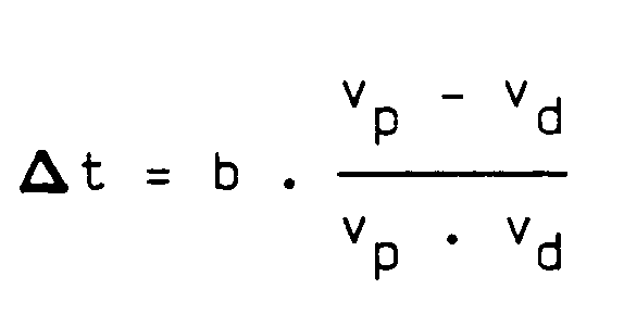
verlängert, wobei vp die Schallgeschwindigkeit im polarisierten Substrat 4 und vd die Schallgeschwindigkeit in der depolarisierten Zone 18 ist.The delay time t on the
extended, where v p is the speed of sound in the polarized substrate 4 and v d is the speed of sound in the
Da die Laufzeit t durch die Depolarisierung der Zone 18 nur verlängert werden kann, muß bei der Dimensionierung der Laufzeitstrecke 14 der erforderliche Korrekturspielraum durch eine entsprechende Verkürzung von L bereitgestellt werden. Die genaue Einstellung der geforderten Verzögerungszeit t erfolgt durch Aneinanderreihen von depolarisierten Zonen 18, wie es in der FIG gestrichelt angedeutet ist.Since the runtime t can only be extended by the depolarization of the
Die nach Abgleich noch zulässige Laufzeittoleranz hängt in erster Linie von der Breite b einer einzigen depolarisierten Zone 18 ab.The runtime tolerance still permissible after adjustment primarily depends on the width b of a single depolarized
Soll diese z.B. ± δt betragen, so erhält man daraus theoretisch die Breite b der depolarisierten Zone 18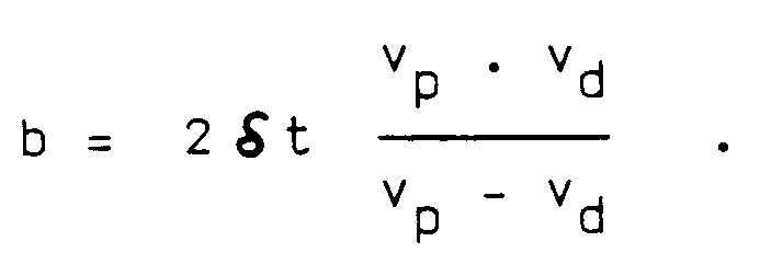
Der Wellenwiderstand der depolarisierten Zone 18 unterscheidet sich vom Wellenwiderstand des polarisierten piezokeramischen Substrates. Dadurch wird ein Teil der Schallwelle reflektiert. Um durch Mehrfachreflexionen bedingte Störsignale zu unterdrücken, können die Grenzflächen zwischen der depolarisierten Zone 18 und dem polarisierten piezokeramischen Material und somit die depolarisierte Zone selbst schräg zur Schallausbreitungsfront ausgerichtet werden.The wave resistance of the depolarized
Besonders vorteilhaft erfolgt die Depolarisierung der Zone 18 berührungslos mit einem Laserstrahl im Scanverfahren. Dabei läßt sich in einfacher Weise die Wellenlänge und die Leistung sowie der Vorschub des Laserstrahls so anpassen, daß gerade die Curietemperatur bzw. die zur vollständigen Depolarisierung erforderliche Temperatur erreicht wird. Eine zu starke Erwärmung wird dadurch vermieden, so daß keine unerwünschte Verbreiterung der depolarisierten Zone 18 durch Wärmeleitung oder Rißbildung im Substrat 4 auftritt.The depolarization of
Da nur relativ kleine Leistungen zur Depolarisierung benötigt werden, kommen auch konventionelle Punktlichtquellen mit geeigneter Fokussierung in Frage. Auch hier erfolgt die Erwärmung berührungslos.Since only relatively small powers are required for depolarization, conventional point light sources with suitable focusing can also be used. Here, too, the heating takes place without contact.
Alternativ zur berührungslosen Erwärmung kann auch mit einem beheizten Element, z.B. einem heizbaren Draht, durch Kontakt das Substrat 4 örtlich erhitzt und damit depolarisiert werden.As an alternative to contactless heating, the substrate 4 can also be locally heated and thus depolarized by contact with a heated element, for example a heatable wire.
Zur Einstellung der gewünschten Verzögerungszeit t kann z.B. nach jeder neu depolarisierten Zone 18 die Verzögerungszeit t gemessen und in Abhängigkeit vom Ergebnis entschieden werden, ob weitere depolarisierte Zonen 18 aufgebracht werden sollen oder ob die bestmögliche Annäherung an den Sollwert erreicht ist.To set the desired delay time t, e.g. After each newly depolarized
Ebenso ist es möglich, aus einer anfangs gemessenen Sollwertabweichung des vollständig polarisierten Substrats 4 die Anzahl der erforderlichen depolarisierten Zonen 18 zu berechnen und dann in einem Zuge ohne weitere Messungen zu depolarisieren.It is also possible to calculate the number of required depolarized
Durch die Anordnung von depolarisierten Zonen 18 in der Laufzeitstrecke 14 von elektroakustischen Bauelementen aus piezokeramischem Material kann das Frequenzverhalten bzw. die Verzögerungszeit dieser Bauelemente sehr eng toleriert werden. Somit können hochgenaue Bauelemente mit großer Bandbreite und geringer Einfügedämpfung auf einfache Art hergestellt werden.The frequency behavior or the delay time of these components can be very closely tolerated by the arrangement of depolarized
Claims (7)
- Electro-acoustic component having a substrate (4) of polarised piezo-ceramic material on which two electro-acoustic transducers (6, 8) are arranged at a distance (L) from each other, characterised in that substrate (4) between the two transducers (6, 8) has a depolarised zone (18) influencing the transit time or the frequency behaviour.
- Electro-acoustic component according to claim 1, characterised in that the depolarised zone (18) extends like a column over the entire width (20) of the substrate (4).
- Electro-acoustic component according to claim 1 or 2, characterised in that the boundary surfaces between the depolarised zone (18) and the polarised piezo-ceramic material are aligned with an inclination to the sound propagation front.
- Process for the production of an electro-acoustic component according to claim 1, characterised in that the piezo-ceramic material is locally heated above the Curie temperature to adjust the transit time or the frequency behaviour.
- Process according to claim 4, characterised in that the local heating is effected by laser light without contact.
- Process according to claim 4, characterised in that the local heating is effected by a focussed point light source without contact.
- Process according to claim 4, characterised in that the local heating is effected by contact with a heating element.
Priority Applications (4)
| Application Number | Priority Date | Filing Date | Title |
|---|---|---|---|
| DE8888115022T DE3881693D1 (en) | 1988-09-14 | 1988-09-14 | ELECTROACOUSTIC COMPONENT MADE OF PIEZOCERAMIC MATERIAL AND METHOD FOR FREQUENCY OR COMPENSATION TIME OF THE COMPONENT. |
| EP88115022A EP0358795B1 (en) | 1988-09-14 | 1988-09-14 | Piezoceramic device for acoustic waves and method for adjusting the frequency and/or the transit time |
| JP1232674A JPH02109409A (en) | 1988-09-14 | 1989-09-07 | Electroacoustic device and its manufacturing method |
| US07/672,751 US5422531A (en) | 1988-09-14 | 1991-03-21 | Electro-acoustic component of piezo ceramic material and method for frequency setting or, respectively, transit time balancing of the component |
Applications Claiming Priority (1)
| Application Number | Priority Date | Filing Date | Title |
|---|---|---|---|
| EP88115022A EP0358795B1 (en) | 1988-09-14 | 1988-09-14 | Piezoceramic device for acoustic waves and method for adjusting the frequency and/or the transit time |
Publications (2)
| Publication Number | Publication Date |
|---|---|
| EP0358795A1 EP0358795A1 (en) | 1990-03-21 |
| EP0358795B1 true EP0358795B1 (en) | 1993-06-09 |
Family
ID=8199310
Family Applications (1)
| Application Number | Title | Priority Date | Filing Date |
|---|---|---|---|
| EP88115022A Expired - Lifetime EP0358795B1 (en) | 1988-09-14 | 1988-09-14 | Piezoceramic device for acoustic waves and method for adjusting the frequency and/or the transit time |
Country Status (4)
| Country | Link |
|---|---|
| US (1) | US5422531A (en) |
| EP (1) | EP0358795B1 (en) |
| JP (1) | JPH02109409A (en) |
| DE (1) | DE3881693D1 (en) |
Families Citing this family (1)
| Publication number | Priority date | Publication date | Assignee | Title |
|---|---|---|---|---|
| US7827115B2 (en) | 2000-04-24 | 2010-11-02 | Visa International Service Association | Online payer authentication service |
Family Cites Families (12)
| Publication number | Priority date | Publication date | Assignee | Title |
|---|---|---|---|---|
| DE2019780C3 (en) * | 1970-04-23 | 1974-07-18 | Siemens Ag, 1000 Berlin Und 8000 Muenchen | Method for the subsequent adjustment of the transit time of electroacoustic delay lines on piezoelectric ceramic substrates |
| CH522978A (en) * | 1970-04-29 | 1972-05-15 | Siemens Ag | Filter or delay line based on the surface wave principle |
| US3699482A (en) * | 1971-06-30 | 1972-10-17 | Ibm | Surface waveguiding in ceramics by selective poling |
| US3750056A (en) * | 1972-03-10 | 1973-07-31 | Zenith Radio Corp | Acoustic surface-wave filters and methods of manufacture therefor |
| DE2231484A1 (en) * | 1972-06-27 | 1974-01-17 | Siemens Ag | METHOD FOR GENERATING REPRODUCTIVE ELECTRIC ALTERNATING FIELDS |
| DE2317761A1 (en) * | 1973-04-09 | 1974-10-24 | Siemens Ag | PROCEDURE FOR ALIGNING THE FREQUENCY AMPLITUDE CHARACTERISTICS OF INTERDIGITAL CONVERTERS |
| US3840826A (en) * | 1973-08-16 | 1974-10-08 | Rca Corp | Variable delay devices using ferroelastic-ferroelectric materials |
| US4037175A (en) * | 1974-01-02 | 1977-07-19 | University Of Illinois Foundation | Variable delay device |
| US3924145A (en) * | 1974-01-02 | 1975-12-02 | Univ Illinois | Surface wave device having a ferroelectric substrate with a sinusoidal pole region |
| US4410823A (en) * | 1981-11-13 | 1983-10-18 | Zenith Radio Corporation | Surface acoustic wave device employing reflectors |
| JPS6089116A (en) * | 1983-10-21 | 1985-05-20 | Matsushita Electric Ind Co Ltd | Method for manufacturing surface acoustic wave devices |
| JPS6194411A (en) * | 1984-10-15 | 1986-05-13 | Clarion Co Ltd | Variable band surface acoustic wave filter |
-
1988
- 1988-09-14 EP EP88115022A patent/EP0358795B1/en not_active Expired - Lifetime
- 1988-09-14 DE DE8888115022T patent/DE3881693D1/en not_active Expired - Lifetime
-
1989
- 1989-09-07 JP JP1232674A patent/JPH02109409A/en active Pending
-
1991
- 1991-03-21 US US07/672,751 patent/US5422531A/en not_active Expired - Lifetime
Also Published As
| Publication number | Publication date |
|---|---|
| US5422531A (en) | 1995-06-06 |
| DE3881693D1 (en) | 1993-07-15 |
| EP0358795A1 (en) | 1990-03-21 |
| JPH02109409A (en) | 1990-04-23 |
Similar Documents
| Publication | Publication Date | Title |
|---|---|---|
| DE69836011T2 (en) | PIEZOELECTRIC THIN LAYER ASSEMBLY | |
| DE69321083T2 (en) | Acoustic surface wave arrangement with interdigital transducer on a substrate carrier and method for production | |
| DE112016003221B4 (en) | Sound wave device and manufacturing method therefor | |
| DE19854729C2 (en) | Method for producing a surface acoustic wave component and for setting its operating frequency | |
| DE3826414A1 (en) | ULTRASONIC THERAPY DEVICE | |
| DE69028003T2 (en) | Surface acoustic wave arrangement | |
| DE19928596A1 (en) | Semiconductor bulk acoustic resonator (SBAR) e.g. for microwave monolithic integrated circuits (MMICs) has viscous damping material located at edges, metal electrodes which are renewing | |
| DE3119272A1 (en) | "BOW SCANNING ULTRASONIC CONVERTER ARRANGEMENT" | |
| DE69607510T2 (en) | Acoustic surface wave resonator filter | |
| DE10143730A1 (en) | A method of setting a frequency characteristic of an edge reflection type surface acoustic wave device and a method of manufacturing an edge reflection type surface acoustic wave device | |
| DE2600393A1 (en) | ELECTRIC FILTERS WITH COUPLED RESONATORS | |
| DE10138080A1 (en) | Micro actuator device, head support assembly and disc recorder | |
| DE1953826A1 (en) | Energy transmission device | |
| DE2255432C3 (en) | Piezoelectric resonator | |
| DE10202856B4 (en) | Surface acoustic wave device | |
| EP0358795B1 (en) | Piezoceramic device for acoustic waves and method for adjusting the frequency and/or the transit time | |
| DE2239696C3 (en) | High frequency piezoelectric thickness resonator and method for its manufacture | |
| DE69316307T2 (en) | vibrator | |
| DE10025337B4 (en) | Laminated piezoelectric component | |
| DE2754494A1 (en) | ELASTIC SURFACE WAVE FILTER | |
| EP0362478B1 (en) | Acoustic delay line | |
| DE19742688C1 (en) | Stacked piezoelectric actuator manufacturing method e.g. for ultrasonic therapy device | |
| DE112006000272B4 (en) | Piezoelectric resonator and method of making the same | |
| EP0487783A1 (en) | Surface wave resonator | |
| DE3536704C2 (en) | SAW component |
Legal Events
| Date | Code | Title | Description |
|---|---|---|---|
| PUAI | Public reference made under article 153(3) epc to a published international application that has entered the european phase |
Free format text: ORIGINAL CODE: 0009012 |
|
| AK | Designated contracting states |
Kind code of ref document: A1 Designated state(s): AT CH DE FR GB LI NL |
|
| RBV | Designated contracting states (corrected) |
Designated state(s): DE FR GB |
|
| 17P | Request for examination filed |
Effective date: 19900410 |
|
| 17Q | First examination report despatched |
Effective date: 19920515 |
|
| GRAA | (expected) grant |
Free format text: ORIGINAL CODE: 0009210 |
|
| AK | Designated contracting states |
Kind code of ref document: B1 Designated state(s): DE FR GB |
|
| REF | Corresponds to: |
Ref document number: 3881693 Country of ref document: DE Date of ref document: 19930715 |
|
| ET | Fr: translation filed | ||
| GBT | Gb: translation of ep patent filed (gb section 77(6)(a)/1977) |
Effective date: 19930908 |
|
| PLBE | No opposition filed within time limit |
Free format text: ORIGINAL CODE: 0009261 |
|
| STAA | Information on the status of an ep patent application or granted ep patent |
Free format text: STATUS: NO OPPOSITION FILED WITHIN TIME LIMIT |
|
| 26N | No opposition filed | ||
| PGFP | Annual fee paid to national office [announced via postgrant information from national office to epo] |
Ref country code: GB Payment date: 19940815 Year of fee payment: 7 |
|
| PGFP | Annual fee paid to national office [announced via postgrant information from national office to epo] |
Ref country code: FR Payment date: 19940920 Year of fee payment: 7 |
|
| PG25 | Lapsed in a contracting state [announced via postgrant information from national office to epo] |
Ref country code: GB Effective date: 19950914 |
|
| GBPC | Gb: european patent ceased through non-payment of renewal fee |
Effective date: 19950914 |
|
| PG25 | Lapsed in a contracting state [announced via postgrant information from national office to epo] |
Ref country code: FR Effective date: 19960531 |
|
| REG | Reference to a national code |
Ref country code: FR Ref legal event code: ST |
|
| PGFP | Annual fee paid to national office [announced via postgrant information from national office to epo] |
Ref country code: DE Payment date: 20071122 Year of fee payment: 20 |