EP0341689A2 - Control apparatus - Google Patents
Control apparatus Download PDFInfo
- Publication number
- EP0341689A2 EP0341689A2 EP89108402A EP89108402A EP0341689A2 EP 0341689 A2 EP0341689 A2 EP 0341689A2 EP 89108402 A EP89108402 A EP 89108402A EP 89108402 A EP89108402 A EP 89108402A EP 0341689 A2 EP0341689 A2 EP 0341689A2
- Authority
- EP
- European Patent Office
- Prior art keywords
- switching
- function
- switching elements
- functions
- signal
- Prior art date
- Legal status (The legal status is an assumption and is not a legal conclusion. Google has not performed a legal analysis and makes no representation as to the accuracy of the status listed.)
- Withdrawn
Links
Images


Classifications
-
- H—ELECTRICITY
- H03—ELECTRONIC CIRCUITRY
- H03K—PULSE TECHNIQUE
- H03K17/00—Electronic switching or gating, i.e. not by contact-making and –breaking
- H03K17/51—Electronic switching or gating, i.e. not by contact-making and –breaking characterised by the components used
- H03K17/56—Electronic switching or gating, i.e. not by contact-making and –breaking characterised by the components used by the use, as active elements, of semiconductor devices
- H03K17/60—Electronic switching or gating, i.e. not by contact-making and –breaking characterised by the components used by the use, as active elements, of semiconductor devices the devices being bipolar transistors
- H03K17/62—Switching arrangements with several input- output-terminals, e.g. multiplexers, distributors
-
- H—ELECTRICITY
- H03—ELECTRONIC CIRCUITRY
- H03K—PULSE TECHNIQUE
- H03K17/00—Electronic switching or gating, i.e. not by contact-making and –breaking
- H03K17/296—Time-programme switches providing a choice of time-intervals for executing more than one switching action and automatically terminating their operation after the programme is completed
Definitions
- the function blocks clock circuit 5, pulse circuit 6, and delay circuit 7 are activated, the keying or latching function taking place primarily to these switching functions by specifying the programming device 1 via the signal line 12 and the function block 4.
- the temporal behavior of the function blocks 4, 5 and 6 is determined by the variable basic frequency 17.
- the fundamental frequency is generated, for example, by a quartz crystal or an RC circuit.
- the circuit arrangement 15 ensures a frequency reduction, which can be selected externally by bridging certain connection pins of the chip.
- the correspondingly reduced fundamental frequency is supplied to the circuit arrangement 4 via signal line 16 and determines the temporal behavior of the clock, pulse and delay circuit.
- the selection circuit 3 performs the corresponding functions of the switching elements K1, K2, K3 to.
Landscapes
- Programmable Controllers (AREA)
- Electronic Switches (AREA)
Abstract
Description
Die Erfindung betrifft ein Befehlsgerät, bestehend aus einem Betätigungselement und einem Gehäuse zur Aufnahme eines oder mehrerer elektronischer Schaltelemente.The invention relates to a control device consisting of an actuating element and a housing for receiving one or more electronic switching elements.
Bekannte Befehlsgeräte der eingangs genannten Art sind in Modultechnik ausgeführt. Die Module sind miteinander kombinierbar, wobei jedes Modul ein kontaktloses Schaltelement mit beliebiger Funktionsweise aufweist. In der DE-OS 26 17 606 wird beispielsweise ein Explosionsgeschützter Paketnockenschalter beschrieben, der aus mehreren formschlüssig aneinandergereihten, gleichförmigen Gehäuseelementen besteht, welche als Universalschaltkammerelemente ausgebildet sind. Jedes dieser Universalschaltkammerelemente kann, nach Anspruch 2, elektronische Schaltelemente mit unterschiedlicher Funktionsweise beinhalten. Die DE-OS 36 11 579 bezieht sich auf ein elektronisches Schaltgerät, das eine in einem Gehäuse befindliche Leiterplatte aufweist, auf der sich eine elektronische Schaltung mit einem Sensor befindet. Dieses elektronische Schaltgerät ist als Modul mit anderen gleichförmigen Modulen zu einem Schaltblock kombinierbar, wobei alle den Schaltblock bildenden Schaltgeräte von nur einem Befehlselement betätigt werden. Auch hierbei ist die Funktionsweise der einzelnen Schaltgerätemodule beliebig. Nach diesem beschriebenen Stand der Technik ist die Änderung der Funktionsweise eines gattungsgemäßen Befehlsgerätes nur mit relativ großem Aufwand durchführbar. Dabei ist für jede Schaltfunktion ein seperates Modul als Kontaktträger zu montieren und entsprechend zu verdrahten. Die indirekte Beeinflussung und Funktionsvorgabe wird z.B. mit einer speicherprogrammierbaren Steuerung realisiert. Hierbei wird ein kontaktloses oder ein kontaktbehaftetes Befehlsgerät mit dem Eingang einer SPS verbunden, welche das Eingangssignal auf gewünschte Schaltfunktionen aufarbeitet. Diese bekannten und gängigen Verfahren haben den Nachteil, daß zum einen ein großer Hardwareaufwand Montage und Verdrahtung betrieben werden muß, und daß sich zum anderen die Zykluszeit der SPS negativ auf das zeitliche Schaltverhalten des Befehlsgerätes auswirkt. Außerdem sind Anwendungsbereiche für Befehlsgeräte gegeben, bei denen aus wirtschaftlichen Gründen der Einsatz einer SPS oder ähnliche Steuerungssysteme nicht tragbar ist.Known control devices of the type mentioned are designed in modular technology. The modules can be combined with one another, each module having a contactless switching element with any function. In DE-OS 26 17 606, for example, an explosion-proof packet cam switch is described, which consists of a plurality of form-fitting, uniform housing elements which are configured as universal switching chamber elements. Each of these universal switching chamber elements can, according to
Die Erfindung stellt sich daher die Aufgabe, ein Befehlsgerät zu schaffen, welches dem Anwender die Möglichkeit bietet, ohne zusätzliche Montage und Verdrahtungsarbeiten, auf einfache Art und Weise die Bestimmung der Schaltfunktion des Befehlsgerätes zu beeinflussen und somit die digitalen Steuerungsanforderungen an die Befehlsebene mit nur einer Befehlsgerätetype zu realisie ren.The invention therefore has as its object to provide a command device which offers the user the possibility of influencing the determination of the switching function of the command device in a simple manner without additional assembly and wiring work, and thus the digital control requirements for the command level with only one Realization device type ren.
Diese Aufgabe wird erfindungsgemäß durch die im Anspruch 1 gekennzeichneten Merkmale gelöst, indem sich in dem Gehäuse befinden:This object is achieved according to the invention by the features characterized in
Funktionsblöcke , die den Schaltelementen als Funktionsangebot zur Verfügung stehen, eine Programmiereinrichtung zur Funktionsvorwahl für die Schaltelemente , die auf einen Eingang einer Auswahlschaltung wirkt, welche die Schaltelemente zur Ausführung der ausgewählten Funktion veranlaßt und Interfaceeinrichtungen zur Signalanpassung der ausgewählten Schaltfunktion an die Schaltelemente.Function blocks that are available to the switching elements as a range of functions, a programming device for function preselection for the switching elements, which acts on an input of a selection circuit which causes the switching elements to carry out the selected function, and interface devices for signal adaptation of the selected switching function to the switching elements.
Vorteilhafte Ausbildungen des erfindungsgemäßen Befehlsgerätes sind in den Unteransprüchen 2 bis 13 gekennzeichnet. Nach den Ansprüchen 2 bis 5 ist es von besonderem Vorteil, daß der Auswahlschaltung durch Beeinflussung der Programmiereinrichtung die Funktion Schließer oder Öffnerverhalten oder die Funktion Schließer oder Öffnerverhalten und verzögertes Schaltverhalten oder die Funktion Schließer oder Öffnerverhalten und monostabiles Schaltverhalten oder die Funktion Schließer oder Öffnerverhalten und astabiles Schaltverhalten zur Verfügung steht. Weiterhin ist es wesentlich, daß nach Anspruch 6 durch Beeinflussung der Programmiereinrichtung der Funktionsblock die Schaltfunktionen Tastend oder Rastend selektiert, wobei der Funktionsblock den Schaltfunktio nen - EIN/AUS, Takt, Impuls Verzögert- übergeordnet ist und daß nach Anspruch 7 das Eingangssignal auf den Funktionsblock einwirkt, der das Funktionsangebot für die Schaltfunktionen -EIN/AUS, Takt, Impuls, Verzögertaktiviert. Nach Anspruch 8 sind Interfaceeinrichtungen vorgesehen sind, die das von der Auswahlschaltung ausgewählte Signal für die Ansteuerung der Schaltelemente auf deren leistungspezifisches Niveau bringen. Vorteilhaft ist es, nach Anspruch 9, daß ein Anschlußelement Einrichtungen zur Aufnahme optischer Statusanzeigen für die Schaltfunktionen jedes Schaltelementes aufweist. Zweckmäßigerweise ist die Schaltungsanordnung, nach Anspruch 10, als integrierter Schaltkreis ausgeführt . Nach Anspruch 11 sind an dem Anschlußelement Einrichtungen zur Aufnahme von Anschlußvorrichtungen vorgesehen , über die die Anschlußleitungen für die Versorgungsspannung, des Eingangssignals, des Resetsignals und des Alarmsignals angeschlossen werden und über die der Schaltsignalabgriff der Schaltelemente erfolgt. Nach den Ansprüchen 12 und 13 ist es zweckmäßig, daß durch die Programmiereinrichtung für jedes Schaltelement gleiche oder unterschiedliche Schaltfunktionen vorgewählt werden und daß unabhängig von der Anzahl der Schaltelemente die Funktionsblöcke einmal vorhanden sind. Schließlich ist es nach den Ansprüchen 14 und 15 von Vorteil daß die Grundfrequenz durch eine Schaltungsanordnung im zeitlichen Verhalten veränderbar ist und daß das zeitliche Verhalten der Funktionsblöcke von der veränderbaren Grundfrequenz abhängig ist.Advantageous embodiments of the control device according to the invention are characterized in the
Nachstehend wird die Erfindung anhand von in der Zeichnung dargestellten, beispielhaften Ausführungsformen näher erläutert.The invention is explained in more detail below on the basis of exemplary embodiments shown in the drawing.
Es zeigen :
- Fig. 1 ein Blockschaltbild der programmierbaren Funktionsvorgabe des erfindungsgemäßen Befehlsgerätes.
- Fig. 2 das Schaltbild der Decodierschaltung und der Ausführungsform der programmierbaren Funktionsvorgabe.
- Fig. 2a die Darstellung der Funktionstabelle für die Programmierung der Schaltfunktionen der elektronischen Schaltelemente K1-K3 nach der Erfindung.
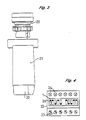
- Fig. 3 das Befehlsgerät mit Betätigungselement Gehäuse und Anschlußelement.
- Fig. 4 das in das Gehäuse integrierte Anschlußelement mit den optischen Statusanzeigen, den Anschlußvorrichtungen und der Programmiereinrichtung.
- Fig. 1 is a block diagram of the programmable function specification of the command device according to the invention.
- Fig. 2 shows the circuit diagram of the decoding circuit and the embodiment of the programmable function specification.
- Fig. 2a shows the function table for programming the switching functions of the electronic switching elements K1-K3 according to the invention.
- Fig. 3, the control device with the actuator housing and connector.
- Fig. 4, the connector integrated into the housing with the optical status indicators, the connecting devices and the programming device.
Fig. 1 zeigt ein Blockschaltbild der programmierbaren Funktionsvorgabe des erfindungsgemäßen Befehlsgerätes mit einer beispielhaften Darstellung für drei Schaltelemente. Die Auswahlschaltung 3 besteht primär aus der in Fig. 2 dargestellten Verknüpfungslogik. Ihr werden die Funktionsvorgaben von den Funktionsblöcken 4, 5, 6, 7, zur Selektierung angeboten und sie ordnet die Funktionen entsprechend der in der Programmiereinheit 1 eingeprägten Vorgaben den Schaltelementen K1, K2, K3 zu. Die Programmierung der Programmiereinheit 1 kann beispielsweise mittels DIP-Schalter 26 erfolgen und wird über die Dekodiereinrichtungen 2 der Auswahlschaltung 3 zugeführt. Die Funktionsvorgabe Schließer- oder Öffnerverhalten wird der Auswahlschaltung 3 mittels der Signalleitung 13 direkt von der Programmiereinrichtung 1 geliefert. Mit dem Eingangssignal INPUT werden die Funktionsblöcke Taktschaltung 5, Impulsschaltung 6, und Verzögerungsschaltung 7 aktiviert, wobei vorrangig zu diesen Schaltfunktionen die Funktion Tastend oder Rastend durch die Vorgabe der Programmiereinrichtung 1 über die Signalleitung 12 und dem Funktionsblock 4 erfolgt. Das zeitliche Verhalten der Funktionsblöcke 4, 5, und 6 wird durch die veränderbare Grundfrequenz 17 bestimmt. Erzeugt wird die Grundfrequenz beispielsweise durch einen Schwingquarz oder eine RC-Schaltung. Die Schaltungsanordnung 15 sorgt für eine Frequenzuntersetzung, die durch Überbrückung bestimmter Anschlußpins des Chips extern gewählt werden kann. Die entsprechend untersetzte Grundfrequenz wird der Schaltungsanordnung 4 über Signalleitung 16 zugeführt und bestimmt das zeitliche Verhalten von Takt, Impuls und Verzögerungsschaltung. Die Auswahlschaltung 3 führt die entsprechenden Funktionen den Schaltelementen K1, K2, K3 zu. Bei der Anfangsinitialisierung, d.h. Spannungszuschaltung oder bei Wiederkehr der Spannung nach einem Spannungseinbruch werden die Interfaceeinrichtungen 8, 9, 10 durch einen externen RESET in einen definierten Schaltzustand gesetzt. Ein externes statisches Signal auf die Eingangsleitung ALARM verursacht ein Sperren aller Interfaceeinrichtungen 8, 9, 10.Fig. 1 shows a block diagram of the programmable function specification of the command device according to the invention with an exemplary representation for three switching elements. The
Fig. 2 zeigt das Schaltbild der Decodiereinrichtung und der Auswahlschaltung für die nach der Fig. 1 dargestellte Ausführungsform der programmierbaren Funktionsvorgabe des erfindungsgemäßen elektronischen Schaltelementes. Mit den von der Programmiereinrichtung 1 kommenden Vorwahlleitungen SA1-SA3, SB1 - SB3 und SC1 - SC3 werden die Funktionsvorgaben für die elektronischen Schaltelemente K1 - K3 zur Dekodiereinrichtung 2 transportiert. Der logische Schaltungsaufbau für die Decodierschaltung 2 und für die Auswahlschaltung 3 ist für jedes Schaltelement gleich. Für das Schaltelement K1 wird mittels der Vorwahlleitung SA1 und des Äquivalentbausteins 30 die Funktion Öffnerverhalten oder Schließerverhalten des Kontaktelementes K1 vorgewählt. Die Vorwahlleitungen SA2 und SA3 bestimmen, je nach ihrem Signalpegel die Schaltfunktion des Schaltelementes K1. Die Decodierung wird durch die logische Verknüpfung der NOR-Bausteine 31 und der NAND-Bausteine 32 innerhalb der Decodierschaltung 2 erreicht. Die Anzahl der Schaltelemente ist in diesem Beispiel auf drei festgelegt, sie kann aber beliebig variiert werden. In der Fig. 2a ist die Funktionstabelle für die Programmierung der Schaltfunktionen der elektronischen Schaltelemente K1-K3 dargestellt. Die Schaltfunktionen EIN/AUS, Takt, Impuls und Verzögert werden direkt der Auswahlschaltung 3 zugeführt und sind für jedes Schaltelement K1-K3 verfügbar. Die programmierte Schaltfunktion wird dem Äquivalenzbaustein 30 über die Eingangsverknüpfung 34 zugeführt. Je nach Signalpegel der Vorwahlleitung SA1 wird das Funktionssignal zu dem NAND-Baustein 33 direkt oder invertiert durchgeschaltet. Hierdurch wird das Öffner/Schließerverhalten erreicht. Durch die Verknüpfung des Funktionssignals mit dem Signal 11, mittels des NAND-Bausteins 33 wird das Schaltelement K1 im Störfall abgeschaltet. Die vorgehende Beschreibung gilt ebenso für die Schaltelemente K2 und K3 entsprechend des Signalpegels ihrer Vorwahlleitungen SB1- SB3 und SC1- SC3. Die Programmierung der Funktionsvorwahl ist in diesem Beispiel mit Vorwahlschaltern, z.B. DIP-Schaltern 26, vorgesehen. Statt der DIP-Schalter könnte die Programmierung auch über andere Programmiermedien erfolgen. Bei Automatisierungssystemen ist beispielsweise die Ansteuerung der Funktionsvorwahl für die Schaltelemente über ein Bussystem oder direkte Ansteuerung durch speicherprogrammierbare Steuerungen vorteilhaft. Das Funktionssignal für die Schaltelemente K1- K3 wird durch die Interfaceein richtungen 8, 9, 10 über Leistungstreiber oder potentialgetrennt über Optokoppler oder anderen Signalaufbereitungselementen den Anschlußvorrichtungen 23 zugeführt.FIG. 2 shows the circuit diagram of the decoding device and the selection circuit for the embodiment of the programmable function specification of the electronic switching element according to the invention shown in FIG. 1. With the preselection lines SA1-SA3, SB1 - SB3 and SC1 - SC3 coming from the
In Fig. 3 ist eine beispielhafte Ausführungsform des Befehlsgerätes mit dem Betätigungselement 20 und dem Gehäuse 21 dargestellt. Das Betätigungselement 20 ist als Einbauelement, beispielsweise in eine Schaltschranktür, vorgesehen. Das Gehäuse 21 ist formschlüssig auf das Betätigungselement aufschnappbar. Das Anschlußelement 22 ist integraler Bestandteil des Gehäuses 21 und in Fig. 4 dargestellt. Die Programmiereinrichtung besteht hierbei aus zehn DIP-Schaltern 26 wobei drei DIP-Schalter für die Funktionsvorgabe eines Schaltelementes vorgesehen sind und ein DIP-Schalter allen vorhandenen Schaltelementen die Funktion Tastend oder Rastend vorgibt. Für jede Funktion sind optische Statusanzeigen 24 vorgesehen. Der Anschluß der Spannungsversorgung, und der Abgriff der Schaltelemente erfolgt an den Anschlschlußvorrichtungen 23. Außerdem ist eine Anschlußmöglichkeit für einen externen Eingang, parallel zum Eingangssignal INPUT des Befehgerätes vorgesehen. Die Anschlußvorrichtungen können in allen bekannten Anschlußtechniken ausgeführt sein.3 shows an exemplary embodiment of the command device with the
Claims (10)
Funktionsblöcke (4, 5, 6, 7), die den Schaltelementen (K1-K3) als Funktionsangebot (EIN/AUS, Takt, Impuls, Verzögert) zur Verfügung stehen,
eine Programmiereinrichtung (1) zur Funktionsvorwahl für die Schaltelemente (K1-K3), die auf einen Eingang (Vorwahl) einer Auswahlschaltung (3) wirkt, welche die Schaltelemente (K1-K3) zur Ausführung der vorgewählten Funktion veranlaßt,
und Interfaceeinrichtungen (8, 9, 10) zur Signalanpassung der ausgewählten Schaltfunktion an die Schaltelemente (K1-K3).1. Command device, consisting of an actuating element and a housing for receiving one or more electronic switching elements, characterized in that in the housing (21) are:
Function blocks (4, 5, 6, 7) that are available to the switching elements (K1-K3) as a range of functions (ON / OFF, clock, pulse, delayed),
a programming device (1) for function preselection for the switching elements (K1-K3), which acts on an input (preselection) of a selection circuit (3) which causes the switching elements (K1-K3) to carry out the preselected function,
and interface devices (8, 9, 10) for signal adaptation of the selected switching function to the switching elements (K1-K3).
Applications Claiming Priority (2)
| Application Number | Priority Date | Filing Date | Title |
|---|---|---|---|
| DE3816369 | 1988-05-13 | ||
| DE19883816369 DE3816369A1 (en) | 1988-05-13 | 1988-05-13 | COMMAND DEVICE WITH ELECTRONIC CONTACT ELEMENTS |
Publications (2)
| Publication Number | Publication Date |
|---|---|
| EP0341689A2 true EP0341689A2 (en) | 1989-11-15 |
| EP0341689A3 EP0341689A3 (en) | 1991-05-22 |
Family
ID=6354318
Family Applications (1)
| Application Number | Title | Priority Date | Filing Date |
|---|---|---|---|
| EP19890108402 Withdrawn EP0341689A3 (en) | 1988-05-13 | 1989-05-10 | Control apparatus |
Country Status (2)
| Country | Link |
|---|---|
| EP (1) | EP0341689A3 (en) |
| DE (1) | DE3816369A1 (en) |
Cited By (1)
| Publication number | Priority date | Publication date | Assignee | Title |
|---|---|---|---|---|
| CN111434508A (en) * | 2019-11-29 | 2020-07-21 | 蜂巢能源科技有限公司 | Control circuits for contactors, power systems and electric vehicles |
Families Citing this family (1)
| Publication number | Priority date | Publication date | Assignee | Title |
|---|---|---|---|---|
| DE20008974U1 (en) | 2000-05-18 | 2000-08-10 | ALSTOM Anlagen- und Automatisierungstechnik GmbH, 28207 Bremen | Input and control device |
Citations (3)
| Publication number | Priority date | Publication date | Assignee | Title |
|---|---|---|---|---|
| US4482947A (en) * | 1982-04-12 | 1984-11-13 | Zenith Electronics Corporation | Multi-function, multi-unit remote control system and method therefor |
| US4545210A (en) * | 1984-04-06 | 1985-10-08 | Carrier Corporation | Electronic program control for a refrigeration unit |
| DE3611579C1 (en) * | 1986-04-07 | 1987-12-10 | Kloeckner Moeller Elektrizit | Electronic switching apparatus |
Family Cites Families (1)
| Publication number | Priority date | Publication date | Assignee | Title |
|---|---|---|---|---|
| DE3418364A1 (en) * | 1984-05-17 | 1985-11-21 | Texas Instruments Deutschland Gmbh, 8050 Freising | Electrically programmable switch device |
-
1988
- 1988-05-13 DE DE19883816369 patent/DE3816369A1/en active Granted
-
1989
- 1989-05-10 EP EP19890108402 patent/EP0341689A3/en not_active Withdrawn
Patent Citations (3)
| Publication number | Priority date | Publication date | Assignee | Title |
|---|---|---|---|---|
| US4482947A (en) * | 1982-04-12 | 1984-11-13 | Zenith Electronics Corporation | Multi-function, multi-unit remote control system and method therefor |
| US4545210A (en) * | 1984-04-06 | 1985-10-08 | Carrier Corporation | Electronic program control for a refrigeration unit |
| DE3611579C1 (en) * | 1986-04-07 | 1987-12-10 | Kloeckner Moeller Elektrizit | Electronic switching apparatus |
Non-Patent Citations (1)
| Title |
|---|
| ELECTRONIQUE APPLICATIONS, Nr. 29, April-Mai 1983, Seiten 23-32; "Un système multi-temporisateurs" * |
Cited By (1)
| Publication number | Priority date | Publication date | Assignee | Title |
|---|---|---|---|---|
| CN111434508A (en) * | 2019-11-29 | 2020-07-21 | 蜂巢能源科技有限公司 | Control circuits for contactors, power systems and electric vehicles |
Also Published As
| Publication number | Publication date |
|---|---|
| DE3816369C2 (en) | 1990-05-23 |
| DE3816369A1 (en) | 1989-11-23 |
| EP0341689A3 (en) | 1991-05-22 |
Similar Documents
| Publication | Publication Date | Title |
|---|---|---|
| DE3341472C2 (en) | Circuit arrangement with a microcomputer | |
| EP0436804A2 (en) | Electrical installation unit for domestic applications | |
| DE3823038A1 (en) | METHOD FOR MONITORING A BATTERY | |
| DE3587103T2 (en) | ELECTRICAL SWITCHING DEVICE AND ELECTRICAL SWITCHING DEVICE WITH AN ADDRESS GENERATOR FOR USE IN SUCH A DEVICE. | |
| EP0600311B1 (en) | Circuit for the safety monitoring of switching devices | |
| DE3125722A1 (en) | CONTROL SYSTEM, ESPECIALLY FOR AUTOMATIC PRODUCTION PLANTS | |
| DE3816369C2 (en) | ||
| DE19606673C1 (en) | Actuator-sensor-interface system | |
| DE112006002699T5 (en) | Washing machine and control method for this | |
| DE60124201T2 (en) | VARIABLE MODE FOR MODBUS NETWORK PROTOCOL | |
| DE2906937A1 (en) | CONTROL SYSTEM FOR THE CONTROL OF A DEVICE WITH A VARIETY OF MACHINE FUNCTIONS | |
| EP0001398A2 (en) | Electronic programme control | |
| DE3321450C2 (en) | Timer-controlled system with several audio components | |
| DE3823788A1 (en) | Arrangement for the connection of wall switches in installation systems | |
| EP1250631B1 (en) | Control system for an industrial sewing machine | |
| DE19734694B4 (en) | Method and device for storing data records on AS-Interface (AS-i) slaves | |
| WO2004042886A2 (en) | Electrical domestic installation system | |
| DE102006047259B4 (en) | Fast bus system based on AS Interface | |
| DE3828434A1 (en) | PROGRAMMABLE LIGHT SWITCH | |
| EP0136579A1 (en) | Circuit with at last one microprocessor having presettable system parameters | |
| DE68915759T2 (en) | BINARY INFORMATION TRANSFER SYSTEM. | |
| DE1763624C3 (en) | Circuit arrangement for triggering switching processes in accordance with the reactive consumption in AC networks | |
| DE1780239C3 (en) | Tone sequence switching device | |
| DE60102886T2 (en) | Electric programmable device | |
| WO1996023357A1 (en) | Circuit for switching the actuator outputs off in an asi system in the event of data communication failure |
Legal Events
| Date | Code | Title | Description |
|---|---|---|---|
| PUAI | Public reference made under article 153(3) epc to a published international application that has entered the european phase |
Free format text: ORIGINAL CODE: 0009012 |
|
| AK | Designated contracting states |
Kind code of ref document: A2 Designated state(s): AT BE CH DE ES FR GB IT LI NL SE |
|
| PUAL | Search report despatched |
Free format text: ORIGINAL CODE: 0009013 |
|
| AK | Designated contracting states |
Kind code of ref document: A3 Designated state(s): AT BE CH DE ES FR GB IT LI NL SE |
|
| RAP1 | Party data changed (applicant data changed or rights of an application transferred) |
Owner name: KLOECKNER-MOELLER GMBH |
|
| 17P | Request for examination filed |
Effective date: 19911031 |
|
| 17Q | First examination report despatched |
Effective date: 19940309 |
|
| STAA | Information on the status of an ep patent application or granted ep patent |
Free format text: STATUS: THE APPLICATION HAS BEEN WITHDRAWN |
|
| 18W | Application withdrawn |
Withdrawal date: 19940521 |
|
| ET | Fr: translation filed |